EP3902602B1 - Multileaf collimator with alternating trapezoidal leaf geometry design - Google Patents
Multileaf collimator with alternating trapezoidal leaf geometry design Download PDFInfo
- Publication number
- EP3902602B1 EP3902602B1 EP19839469.4A EP19839469A EP3902602B1 EP 3902602 B1 EP3902602 B1 EP 3902602B1 EP 19839469 A EP19839469 A EP 19839469A EP 3902602 B1 EP3902602 B1 EP 3902602B1
- Authority
- EP
- European Patent Office
- Prior art keywords
- type
- blocking
- source
- leaves
- blocking leaves
- Prior art date
- Legal status (The legal status is an assumption and is not a legal conclusion. Google has not performed a legal analysis and makes no representation as to the accuracy of the status listed.)
- Active
Links
Images



Classifications
-
- A—HUMAN NECESSITIES
- A61—MEDICAL OR VETERINARY SCIENCE; HYGIENE
- A61N—ELECTROTHERAPY; MAGNETOTHERAPY; RADIATION THERAPY; ULTRASOUND THERAPY
- A61N5/00—Radiation therapy
- A61N5/10—X-ray therapy; Gamma-ray therapy; Particle-irradiation therapy
- A61N5/1042—X-ray therapy; Gamma-ray therapy; Particle-irradiation therapy with spatial modulation of the radiation beam within the treatment head
- A61N5/1045—X-ray therapy; Gamma-ray therapy; Particle-irradiation therapy with spatial modulation of the radiation beam within the treatment head using a multi-leaf collimator, e.g. for intensity modulated radiation therapy or IMRT
-
- A—HUMAN NECESSITIES
- A61—MEDICAL OR VETERINARY SCIENCE; HYGIENE
- A61B—DIAGNOSIS; SURGERY; IDENTIFICATION
- A61B6/00—Apparatus or devices for radiation diagnosis; Apparatus or devices for radiation diagnosis combined with radiation therapy equipment
- A61B6/06—Diaphragms
-
- A—HUMAN NECESSITIES
- A61—MEDICAL OR VETERINARY SCIENCE; HYGIENE
- A61N—ELECTROTHERAPY; MAGNETOTHERAPY; RADIATION THERAPY; ULTRASOUND THERAPY
- A61N5/00—Radiation therapy
- A61N5/10—X-ray therapy; Gamma-ray therapy; Particle-irradiation therapy
- A61N5/1077—Beam delivery systems
- A61N5/1081—Rotating beam systems with a specific mechanical construction, e.g. gantries
-
- G—PHYSICS
- G21—NUCLEAR PHYSICS; NUCLEAR ENGINEERING
- G21K—HANDLING OF PARTICLES OR IONISING RADIATION NOT OTHERWISE PROVIDED FOR; IRRADIATION DEVICES; GAMMA RAY OR X-RAY MICROSCOPES
- G21K1/00—Arrangements for handling particles or ionising radiation, e.g. focusing or moderating
- G21K1/02—Arrangements for handling particles or ionising radiation, e.g. focusing or moderating using diaphragms, collimators
-
- G—PHYSICS
- G21—NUCLEAR PHYSICS; NUCLEAR ENGINEERING
- G21K—HANDLING OF PARTICLES OR IONISING RADIATION NOT OTHERWISE PROVIDED FOR; IRRADIATION DEVICES; GAMMA RAY OR X-RAY MICROSCOPES
- G21K1/00—Arrangements for handling particles or ionising radiation, e.g. focusing or moderating
- G21K1/02—Arrangements for handling particles or ionising radiation, e.g. focusing or moderating using diaphragms, collimators
- G21K1/025—Arrangements for handling particles or ionising radiation, e.g. focusing or moderating using diaphragms, collimators using multiple collimators, e.g. Bucky screens; other devices for eliminating undesired or dispersed radiation
-
- G—PHYSICS
- G21—NUCLEAR PHYSICS; NUCLEAR ENGINEERING
- G21K—HANDLING OF PARTICLES OR IONISING RADIATION NOT OTHERWISE PROVIDED FOR; IRRADIATION DEVICES; GAMMA RAY OR X-RAY MICROSCOPES
- G21K1/00—Arrangements for handling particles or ionising radiation, e.g. focusing or moderating
- G21K1/02—Arrangements for handling particles or ionising radiation, e.g. focusing or moderating using diaphragms, collimators
- G21K1/04—Arrangements for handling particles or ionising radiation, e.g. focusing or moderating using diaphragms, collimators using variable diaphragms, shutters, choppers
-
- G—PHYSICS
- G21—NUCLEAR PHYSICS; NUCLEAR ENGINEERING
- G21K—HANDLING OF PARTICLES OR IONISING RADIATION NOT OTHERWISE PROVIDED FOR; IRRADIATION DEVICES; GAMMA RAY OR X-RAY MICROSCOPES
- G21K1/00—Arrangements for handling particles or ionising radiation, e.g. focusing or moderating
- G21K1/02—Arrangements for handling particles or ionising radiation, e.g. focusing or moderating using diaphragms, collimators
- G21K1/04—Arrangements for handling particles or ionising radiation, e.g. focusing or moderating using diaphragms, collimators using variable diaphragms, shutters, choppers
- G21K1/043—Arrangements for handling particles or ionising radiation, e.g. focusing or moderating using diaphragms, collimators using variable diaphragms, shutters, choppers changing time structure of beams by mechanical means, e.g. choppers, spinning filter wheels
-
- A—HUMAN NECESSITIES
- A61—MEDICAL OR VETERINARY SCIENCE; HYGIENE
- A61N—ELECTROTHERAPY; MAGNETOTHERAPY; RADIATION THERAPY; ULTRASOUND THERAPY
- A61N5/00—Radiation therapy
- A61N5/10—X-ray therapy; Gamma-ray therapy; Particle-irradiation therapy
- A61N2005/1092—Details
- A61N2005/1095—Elements inserted into the radiation path within the system, e.g. filters or wedges
-
- G—PHYSICS
- G21—NUCLEAR PHYSICS; NUCLEAR ENGINEERING
- G21K—HANDLING OF PARTICLES OR IONISING RADIATION NOT OTHERWISE PROVIDED FOR; IRRADIATION DEVICES; GAMMA RAY OR X-RAY MICROSCOPES
- G21K1/00—Arrangements for handling particles or ionising radiation, e.g. focusing or moderating
- G21K1/02—Arrangements for handling particles or ionising radiation, e.g. focusing or moderating using diaphragms, collimators
- G21K1/04—Arrangements for handling particles or ionising radiation, e.g. focusing or moderating using diaphragms, collimators using variable diaphragms, shutters, choppers
- G21K1/046—Arrangements for handling particles or ionising radiation, e.g. focusing or moderating using diaphragms, collimators using variable diaphragms, shutters, choppers varying the contour of the field, e.g. multileaf collimators
-
- G—PHYSICS
- G21—NUCLEAR PHYSICS; NUCLEAR ENGINEERING
- G21K—HANDLING OF PARTICLES OR IONISING RADIATION NOT OTHERWISE PROVIDED FOR; IRRADIATION DEVICES; GAMMA RAY OR X-RAY MICROSCOPES
- G21K5/00—Irradiation devices
- G21K5/04—Irradiation devices with beam-forming means
Definitions
- This invention relates generally to radiation apparatuses.
- various embodiments of multileaf collimators with alternating trapezoidal leaf geometry design are described.
- Multileaf collimators are widely used in radiotherapy machines to support various forms of treatment including 3D conformal radiation therapy (3D-CRT), intensity-modulated radiotherapy (IMRT), volumetric modulated arc therapy (VMAT), etc.
- An MLC includes a plurality pairs of beam-blocking leaves arranged in opposing banks. Individual beam-blocking leaves can be independently moved in and out of a radiation beam to block or modify the beam. In use, selected beam-blocking leaves can be positioned in the radiation beam, forming one or more apertures through which the unblocked radiation beam passes. The aperture(s) define(s) the shape of the radiation beam directed to a treatment field at an isocenter.
- the interleaf gap or tolerance can be a source of radiation leakage in an MLC.
- the interleaf tolerance may also cause the leaves to flop when the MLC or the gantry supporting the MLC rotates such that the amount of interleaf leakage is unpredictable. Controlling the amount of interleaf leakage for all gantry and collimator angles is also important so that the radiation delivered by the radiation system to the target is of acceptable quality.
- U.S. Pat. No. 7,742,575 B2 discloses an MLC in which the beam-blocking leaves are held to be shifted or orientated such that the sides or faces of the leaves align with a convergence point which offsets the radiation source. As such, beams from the radiation source would strike the beam-blocking leaves at an angle, avoiding the gap between the adjacent leaves through which radiation could pass uninterrupted.
- the asymmetrical shift of the beam-blocking leaves from the radiation source creates variations in penumbra and resolution across the entire field.
- the present invention provides a multileaf collimator as defined in claim 1. In another aspect, the present invention provides a multi-level multileaf collimator as defined in claim 6. In a further aspect, the present invention provides an apparatus as defined in claim 9. Optional features are specified in the dependent claims.
- Embodiments of this disclosure provide for a multileaf collimator (MLC) having an alternating trapezoidal leaf geometry design.
- MLC multileaf collimator
- the novel leaf geometry design can reduce MLC interleaf leakage, provide predictability of interleaf leakage regardless of dynamic rotation of the MLC, and maintains uniform side leaf penumbra across the treatment field.
- the flat sided, trapezoidal leaf geometry design allows for reduction of the manufacturing costs of each individual leaf, and thus the MLC.
- a multileaf collimator comprises a plurality of beam-blocking leaves of a first type and a plurality of beam-blocking leaves of a second type.
- Each of the beam-blocking leaves of the first type has a trapezoidal geometry viewed in the longitudinal moving direction comprising a first lateral side, a second lateral side, a wider end and a narrower end with the wider end being proximal to a source.
- Each of the beam-blocking leaves of the second type has a trapezoidal geometry viewed in the longitudinal moving direction comprising a first lateral side, a second lateral side, a wider end and a narrower end with the wider end being distal to the source.
- the beam-blocking leaves of the first type are alternatingly arranged with the beam-blocking leaves of the second type side by side.
- the first lateral sides of the trapezoidal geometry of the plurality of beam-blocking leaves of the first type may align to converge to a first point offset from the source.
- the second lateral sides of the trapezoidal geometry of the plurality of beam-blocking leaves of the first type may align to converge to a second point offset from the source opposite to the first point.
- the first lateral sides of the trapezoidal geometry of the plurality of beam-blocking leaves of the second type may align to converge to the second point, and the second lateral sides of the trapezoidal geometry of the plurality of beam-blocking leaves of the second type may align to converge to the first point.
- the first and second lateral sides of the plurality of beam-blocking leaves of the first type and the first and second lateral sides of the plurality of beam-blocking leaves of the second type may be substantially flat.
- a multi-level multileaf collimator comprises a first MLC in a first level distal to a source and a second MLC in a second level proximal to the source.
- the second MLC comprises a plurality of beam-blocking leaves of a first type and a plurality of beam-blocking leaves of a second type.
- Each of the beam-blocking leaves of the first type has a trapezoidal geometry viewed in the longitudinal moving direction comprising a first lateral side, a second lateral side, a wider end and a narrower end with the wider end being proximal to a source.
- Each of the beam-blocking leaves of the second type has a trapezoidal geometry viewed in the longitudinal moving direction comprising a first lateral side, a second lateral side, a wider end and a narrower end with the wider end being distal to the source.
- the beam-blocking leaves of the first type are alternatingly arranged with the beam-blocking leaves of the second type side by side.
- the plurality of beam-blocking leaves of the first MLC may be longitudinally movable in a direction substantially parallel with the longitudinal moving direction of the beam-blocking leaves of the second MLC.
- Each of the beam-blocking leaves of the first and second types of the second MLC may laterally offset a beam-blocking leaf of the first MLC.
- an apparatus in one embodiment, includes a source of radiation, and a multileaf collimator comprising a plurality of beam-blocking leaves of a first type and a plurality of beam-blocking leaves of a second type.
- Each of the beam-blocking leaves of the first type has a trapezoidal geometry viewed in the longitudinal moving direction comprising a first lateral side, a second lateral side, a wider end and a narrower end with the wider end being proximal to a source.
- Each of the beam-blocking leaves of the second type has a trapezoidal geometry viewed in the longitudinal moving direction comprising a first lateral side, a second lateral side, a wider end and a narrower end with the wider end being distal to the source.
- the beam-blocking leaves of the first type are alternatingly arranged with the beam-blocking leaves of the second type side by side.
- the source of radiation may be a source of x-rays, a source of gamma rays, a source of protons, or a source of heavy ions.
- MLCs multileaf collimators
- FIG. 1 is a simplified illustration of a radiation system including an MLC according to embodiments of the disclosure.
- the radiation system 100 may include a radiation source 102 configured to produce a beam 103 of radiation such as photons, electrons, protons, or other types of radiation.
- the radiation source 102 may include a metallic target configured to produce a beam of x-rays upon impingement of electrons.
- the radiation system 100 may include various beam shaping components such as a primary collimator 104 and optionally a secondary collimator 106 to generally limit the extent of the beam 103 as it travels away from the source 102 toward an isocenter plane 108.
- An MLC 110 such as a multi-level MLC is disposed between the source 102 and the isocenter plane 108 to further shape the beam, as indicated by the shaped field 112 in the isocenter plane 108, according to a general use embodiment of the MLC.
- the MLC 110 may rotate about the beamline or axis 109 passing through the source 102, placing the MLC in various orientations.
- the source 102, primary collimator 104, secondary collimator 106, and the MLC 110 may be enclosed in a treatment head (not shown), which can be rotated by a gantry (not shown) about an axis such as a horizontal axis 111.
- the radiation system 100 can deliver treatment beams to a target in the isocenter plane 108 from various angles.
- the shape, size, and/or intensity of the beam 103 can be adjusted or dynamically adjusted by the MLC 110 as the beam angle is stepped or swept around the target.
- the MLC 110 may be a single level MLC or a multi-level MLC as shown.
- the MLC 110 may include a first MLC 120 in a first level distal to the source 102 and a second MLC 130 in a second level proximal to the source 102.
- MLC multileaf collimator
- the term "multileaf collimator" or "MLC” refers to a collection of a plurality of beam-blocking leaves each of which can be longitudinally moved in and out of a beam to modify one or more parameters of the beam such as the beam shape, size, energy, or intensity etc.
- Each beam-blocking leaf may be driven by a motor with a lead screw or other suitable means.
- the beam-blocking leaves may be arranged in pairs.
- the beam-blocking leaves of each pair may be brought in contact or retracted from each other to close or open a path for a radiation beam to pass through the MLC.
- the beam-blocking leaves may be arranged in opposing banks and supported by a frame, box, carriage or other support structure, which has features allowing the individual beam-blocking leaves to extend into and retract from the beam.
- the frame, box, carriage or other support structure can be further moved or translated in addition to the individual leaf travel.
- the first and second MLCs 120, 130 may be arranged such that the moving direction of individual beam-blocking leaves of the first and second MLCs 120, 130 are generally in parallel.
- the beam-blocking leaves 122 of the first MLC 120 in the first level are longitudinally movable in the x-direction
- the beam-blocking leaves 132 of the second MLC 130 in the second level are also longitudinally movable in the x-direction
- the first and second MLCs may be arranged such that the moving direction of the beam-blocking leaves of the first MLC is non-parallel e.g. perpendicular to the moving direction of the beam-blocking leaves of the second MLC.
- the first and second MLCs 120, 130 may be arranged such that the leaves 132 of the second MLC 130 may laterally offset the leaves 122 of the first MLC 120 in a beam's eye view, or as viewed in a direction from the source 102.
- FIG. 2 is a cross-sectional view of a portion of the multi-level MLC 110 of FIG. 1 taken along line A-A, showing the lateral offset arrangement of the leaves of the multi-level MLC 110.
- a leaf 132 of the second MLC 130 in the second level offsets a leaf 122 of the first MLC 120 in the first level as viewed from the source 102.
- a leaf 132 of the second MLC 130 may offset a leaf 122 of the first MLC 120 by substantially half a leaf.
- a gap between two adjacent leaves 132 of the second MLC 130 in the second level may be positioned substantially at the middle of a leaf 122 of the first MLC 120.
- the lateral offset arrangement of leaves in different levels provides for leaf projections that are also offset at the isocenter plane. Therefore, the lateral offset arrangement of leaves may provide for substantially an equivalent of doubling MLC definition, or improving the resolution to half as compared to the definition of a single level MLC with leaves of the same physical width.
- three or more MLCs may be arranged in three or more levels such that each leaf at a level may offset e.g.
- the MLC 110 may include beam-blocking leaves having a trapezoidal geometry viewed in the leaf longitudinal moving direction.
- trapezoidal geometry or its grammatic equivalent refers to a geometry including a wider end and a narrower end parallel to each other and two lateral sides connecting the wider and narrower ends.
- the lateral sides of the beam-blocking leaves are substantially flat.
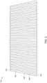
- FIG. 3 depicts a bank of beam-blocking leaves 140 of an exemplary MLC 110 having a trapezoidal geometry design according to embodiments of the disclosure.
- a beam-blocking leaf 140 of a trapezoidal geometry design may include a wider end 142 and a narrower end 144 parallel to each other, and a first or left lateral side 146 and a second or right lateral side 148 connecting the wider and narrower ends 142, 144.
- the plurality of beam-blocking leaves 140 of trapezoidal geometry design may be arranged such that the beam-blocking leaves whose wider ends are proximal to the source alternate with the beam-blocking leaves whose wider ends are distal to the source.
- the term "beam-blocking leaf of a first type” or its grammatic equivalent may be used to refer to a beam-blocking leaf having a trapezoidal geometry with the wider end being arranged proximal to the radiation source.
- beam-blocking leaf of a second type or its grammatic equivalent may be used to refer to a beam-blocking leaf having a trapezoidal geometry with the wider end being arranged distal to the radiation source.
- the MLC 110 may include a plurality of beam-blocking leaves of a first type and a plurality of beam-blocking leaves of a second type, where the beam-blocking leaves of the first type are alternatingly arranged with the beam-blocking leaves of the second type side by side.
- FIG. 4 illustrates a sub-set of beam-blocking leaves 140 in an exemplary MLC 110 according to embodiments of the disclosure, showing the alternating arrangement of the beam-blocking leaves.
- each of the beam-blocking leaves 140 has a trapezoidal geometry design as viewed in the leaf longitudinal moving direction.
- the MLC 110 includes beam-blocking leaves of the first type 140a, with the wider end being proximal to the source, and beam-blocking leaves of the second type 140b, with the wider end being distal to the source.
- the beam-blocking leaves of the first type 140a alternate with the beam-blocking leaves of the second type 140b side by side.
- the beam-blocking leaves of the first and second types can be designed and constructed such that when fitted, the first or left lateral sides of the beam-blocking leaves of the first type align to converge to a first point offset from the radiation source, and the second or right lateral sides of the beam-blocking leaves of the first type align to converge to a second point offset from the source.
- the first or left lateral sides of the beam-blocking leaves may align to converge to the second point offset from the source and the second or right lateral sides align to converge to the first point offset from the source.
- the left or first lateral sides 146a of the plurality of beam-blocking leaves of the first type 140a align to converge to a point 102a, which offsets the radiation source 102 at a distance (-X).
- the right or second lateral sides 148a of the plurality of beam-blocking leaves of the first type 140a align to converge to a point 102b which offsets the radiation source 102 at a distance (+X).
- the left or first lateral sides 146b of the plurality of beam-blocking leaves of the second type 140b which face or are adjacent to the right or second lateral sides 148a of the beam-blocking leaves of the first type 140a, align to converge to the second point 102b, which offsets the radiation source 102 at a distance (+X).
- the right or second lateral sides 148b of the plurality of beam-blocking leaves of the second type 140b which face or are adjacent to the left or first sides 146a of the beam-blocking leaves of the first type 140a, align to converge to the first point 102a, which offsets the radiation source 102 at a distance (-X).
- the first converging point 102a may offset the radiation source 102 at a distance substantially equal to the distance that the second converging point 102b offsets the radiation source 102 at an opposite side.
- the alternating trapezoidal geometry design of the beam-blocking leaves allows the flat side surfaces of adjacent leaves to be slightly "off-focus" relative to the radiation source 102, hence change the angle of the path or gap between adjacent beam-blocking leaves that a radiating beam from the source 102 would pass.
- the left lateral side 146a of beam-blocking leaf 140a forms an angle with a line passing the middle point (M) of the lateral side 146a and the source 102.
- the right lateral side 148a of beam-blocking leaf 140a forms an angle with a line passing the middle point (M) of the right lateral side 148a and the source 102.
- the plurality of beam-blocking leaves 140 can be designed and constructed such that these off-focus angles are consistent for each of the beam-blocking leaves regardless of the location of the leaf in the leaf bank, providing symmetrical penumbra and resolution for the entire treatment field.
- the alternating trapezoidal leaf geometry design provides for improved packing of drive motors for the beam-blocking leaves because it can slit half of the motors to the proximal part of the leaf bank and half of the motors to the distal part of the leaf bank. This provides for more room for the leaf drive system including motors, lead screws etc., allowing for a more robust and reliable design.
- the alternating trapezoidal leaf geometry design can also reduce the costs of constructing an MLC because the boxes or support structures for both banks of the beam-blocking leaves can be made identical, reducing the number of parts and ultimately reducing the costs.
Landscapes
- Health & Medical Sciences (AREA)
- Engineering & Computer Science (AREA)
- Physics & Mathematics (AREA)
- Biomedical Technology (AREA)
- Life Sciences & Earth Sciences (AREA)
- High Energy & Nuclear Physics (AREA)
- Radiology & Medical Imaging (AREA)
- Animal Behavior & Ethology (AREA)
- Nuclear Medicine, Radiotherapy & Molecular Imaging (AREA)
- Pathology (AREA)
- Veterinary Medicine (AREA)
- Public Health (AREA)
- General Health & Medical Sciences (AREA)
- Spectroscopy & Molecular Physics (AREA)
- General Engineering & Computer Science (AREA)
- Medical Informatics (AREA)
- Surgery (AREA)
- Molecular Biology (AREA)
- Heart & Thoracic Surgery (AREA)
- Biophysics (AREA)
- Optics & Photonics (AREA)
- Radiation-Therapy Devices (AREA)
- Apparatus For Radiation Diagnosis (AREA)
Description
- This invention relates generally to radiation apparatuses. In particular, various embodiments of multileaf collimators with alternating trapezoidal leaf geometry design are described.
- Multileaf collimators (MLCs) are widely used in radiotherapy machines to support various forms of treatment including 3D conformal radiation therapy (3D-CRT), intensity-modulated radiotherapy (IMRT), volumetric modulated arc therapy (VMAT), etc. An MLC includes a plurality pairs of beam-blocking leaves arranged in opposing banks. Individual beam-blocking leaves can be independently moved in and out of a radiation beam to block or modify the beam. In use, selected beam-blocking leaves can be positioned in the radiation beam, forming one or more apertures through which the unblocked radiation beam passes. The aperture(s) define(s) the shape of the radiation beam directed to a treatment field at an isocenter.
- Tolerance or gap between adjacent beam-blocking leaves in an MLC exists or is provided to allow dynamic linear or longitudinal movement of the leaves. The interleaf gap or tolerance can be a source of radiation leakage in an MLC. The interleaf tolerance may also cause the leaves to flop when the MLC or the gantry supporting the MLC rotates such that the amount of interleaf leakage is unpredictable. Controlling the amount of interleaf leakage for all gantry and collimator angles is also important so that the radiation delivered by the radiation system to the target is of acceptable quality.
- To mitigate MLC interleaf leakage, various leaf designs are developed, including "tongue in groove" designs in which steps or similar geometries are provided on the leaf sides so that leaf materials mutually overlap between leaves. Manufacturing of beam-blocking leaves with a "tongue in groove" design can be very expensive. Further, while a "tongue in groove" design may reduce interleaf leakage, it may lead to undesirable underdose effects when MLC treatment fields are combined.
-
U.S. Pat. No. 7,742,575 B2 discloses an MLC in which the beam-blocking leaves are held to be shifted or orientated such that the sides or faces of the leaves align with a convergence point which offsets the radiation source. As such, beams from the radiation source would strike the beam-blocking leaves at an angle, avoiding the gap between the adjacent leaves through which radiation could pass uninterrupted. The asymmetrical shift of the beam-blocking leaves from the radiation source creates variations in penumbra and resolution across the entire field. - In one aspect, the present invention provides a multileaf collimator as defined in claim 1. In another aspect, the present invention provides a multi-level multileaf collimator as defined in claim 6. In a further aspect, the present invention provides an apparatus as defined in claim 9. Optional features are specified in the dependent claims.
- Embodiments of this disclosure provide for a multileaf collimator (MLC) having an alternating trapezoidal leaf geometry design. The novel leaf geometry design can reduce MLC interleaf leakage, provide predictability of interleaf leakage regardless of dynamic rotation of the MLC, and maintains uniform side leaf penumbra across the treatment field. The flat sided, trapezoidal leaf geometry design allows for reduction of the manufacturing costs of each individual leaf, and thus the MLC.
- In one embodiment, a multileaf collimator comprises a plurality of beam-blocking leaves of a first type and a plurality of beam-blocking leaves of a second type. Each of the beam-blocking leaves of the first type has a trapezoidal geometry viewed in the longitudinal moving direction comprising a first lateral side, a second lateral side, a wider end and a narrower end with the wider end being proximal to a source. Each of the beam-blocking leaves of the second type has a trapezoidal geometry viewed in the longitudinal moving direction comprising a first lateral side, a second lateral side, a wider end and a narrower end with the wider end being distal to the source. The beam-blocking leaves of the first type are alternatingly arranged with the beam-blocking leaves of the second type side by side.
- The first lateral sides of the trapezoidal geometry of the plurality of beam-blocking leaves of the first type may align to converge to a first point offset from the source. The second lateral sides of the trapezoidal geometry of the plurality of beam-blocking leaves of the first type may align to converge to a second point offset from the source opposite to the first point.
- The first lateral sides of the trapezoidal geometry of the plurality of beam-blocking leaves of the second type may align to converge to the second point, and the second lateral sides of the trapezoidal geometry of the plurality of beam-blocking leaves of the second type may align to converge to the first point. The first and second lateral sides of the plurality of beam-blocking leaves of the first type and the first and second lateral sides of the plurality of beam-blocking leaves of the second type may be substantially flat.
- In one embodiment, a multi-level multileaf collimator (MLC) comprises a first MLC in a first level distal to a source and a second MLC in a second level proximal to the source. The second MLC comprises a plurality of beam-blocking leaves of a first type and a plurality of beam-blocking leaves of a second type. Each of the beam-blocking leaves of the first type has a trapezoidal geometry viewed in the longitudinal moving direction comprising a first lateral side, a second lateral side, a wider end and a narrower end with the wider end being proximal to a source. Each of the beam-blocking leaves of the second type has a trapezoidal geometry viewed in the longitudinal moving direction comprising a first lateral side, a second lateral side, a wider end and a narrower end with the wider end being distal to the source. The beam-blocking leaves of the first type are alternatingly arranged with the beam-blocking leaves of the second type side by side.
- The plurality of beam-blocking leaves of the first MLC may be longitudinally movable in a direction substantially parallel with the longitudinal moving direction of the beam-blocking leaves of the second MLC. Each of the beam-blocking leaves of the first and second types of the second MLC may laterally offset a beam-blocking leaf of the first MLC.
- In one embodiment, an apparatus includes a source of radiation, and a multileaf collimator comprising a plurality of beam-blocking leaves of a first type and a plurality of beam-blocking leaves of a second type. Each of the beam-blocking leaves of the first type has a trapezoidal geometry viewed in the longitudinal moving direction comprising a first lateral side, a second lateral side, a wider end and a narrower end with the wider end being proximal to a source. Each of the beam-blocking leaves of the second type has a trapezoidal geometry viewed in the longitudinal moving direction comprising a first lateral side, a second lateral side, a wider end and a narrower end with the wider end being distal to the source. The beam-blocking leaves of the first type are alternatingly arranged with the beam-blocking leaves of the second type side by side.
- The source of radiation may be a source of x-rays, a source of gamma rays, a source of protons, or a source of heavy ions.
- This Summary is provided to introduce selected aspects and embodiments of this disclosure in a simplified form and is not intended to identify key features or essential characteristics of the claimed subject matter, nor is it intended to be used as an aid in determining the scope of the claimed subject matter. The selected aspects and embodiments are presented merely to provide the reader with a brief summary of certain forms the invention might take and are not intended to limit the scope of the invention. Other aspects and embodiments of the disclosure are described in the section of Detailed Description.
- These and various other features and advantages will become better understood upon reading of the following detailed description in conjunction with the accompanying drawings provided below, where:
-
FIG. 1 is a simplified illustration of a radiation system including a multileaf collimator (MLC) in accordance with embodiments of this disclosure; -
FIG. 2 is a cross-sectional view of the exemplary MLC shown inFIG. 1 , taken along line A-A. -
FIG. 3 depicts a bank of beam-blocking leaves of an exemplary MLC as viewed in the leaf longitudinal moving direction according to embodiments of the disclosure. -
FIG. 4 depicts a sub-set of beam-blocking leaves in the exemplary MLC shown inFIG. 3 according to embodiments of the disclosure. -
FIG. 5 illustrates various features of an alternating trapezoidal leaf geometry design of an MLC according to embodiments of the disclosure. - Referring to
FIGS. 1-5 , various embodiments of multileaf collimators (MLCs) with an alternating trapezoidal leaf geometry design will now be described. -
FIG. 1 is a simplified illustration of a radiation system including an MLC according to embodiments of the disclosure. As shown, theradiation system 100 may include aradiation source 102 configured to produce abeam 103 of radiation such as photons, electrons, protons, or other types of radiation. For example, theradiation source 102 may include a metallic target configured to produce a beam of x-rays upon impingement of electrons. Theradiation system 100 may include various beam shaping components such as aprimary collimator 104 and optionally asecondary collimator 106 to generally limit the extent of thebeam 103 as it travels away from thesource 102 toward anisocenter plane 108. AnMLC 110 such as a multi-level MLC is disposed between thesource 102 and theisocenter plane 108 to further shape the beam, as indicated by the shapedfield 112 in theisocenter plane 108, according to a general use embodiment of the MLC. TheMLC 110 may rotate about the beamline oraxis 109 passing through thesource 102, placing the MLC in various orientations. Thesource 102,primary collimator 104,secondary collimator 106, and theMLC 110 may be enclosed in a treatment head (not shown), which can be rotated by a gantry (not shown) about an axis such as a horizontal axis 111. Thus, theradiation system 100 can deliver treatment beams to a target in theisocenter plane 108 from various angles. The shape, size, and/or intensity of thebeam 103 can be adjusted or dynamically adjusted by theMLC 110 as the beam angle is stepped or swept around the target. - The
MLC 110 may be a single level MLC or a multi-level MLC as shown. By way of example, theMLC 110 may include afirst MLC 120 in a first level distal to thesource 102 and asecond MLC 130 in a second level proximal to thesource 102. As used herein, the term "multileaf collimator" or "MLC" refers to a collection of a plurality of beam-blocking leaves each of which can be longitudinally moved in and out of a beam to modify one or more parameters of the beam such as the beam shape, size, energy, or intensity etc. Each beam-blocking leaf may be driven by a motor with a lead screw or other suitable means. The beam-blocking leaves may be arranged in pairs. The beam-blocking leaves of each pair may be brought in contact or retracted from each other to close or open a path for a radiation beam to pass through the MLC. The beam-blocking leaves may be arranged in opposing banks and supported by a frame, box, carriage or other support structure, which has features allowing the individual beam-blocking leaves to extend into and retract from the beam. The frame, box, carriage or other support structure can be further moved or translated in addition to the individual leaf travel. - As shown in
FIG. 1 , the first andsecond MLCs second MLCs FIG. 1 the beam-blockingleaves 122 of thefirst MLC 120 in the first level are longitudinally movable in the x-direction, and the beam-blockingleaves 132 of thesecond MLC 130 in the second level are also longitudinally movable in the x-direction Alternatively, the first and second MLCs may be arranged such that the moving direction of the beam-blocking leaves of the first MLC is non-parallel e.g. perpendicular to the moving direction of the beam-blocking leaves of the second MLC. - The first and
second MLCs leaves 132 of thesecond MLC 130 may laterally offset theleaves 122 of thefirst MLC 120 in a beam's eye view, or as viewed in a direction from thesource 102.FIG. 2 is a cross-sectional view of a portion of themulti-level MLC 110 ofFIG. 1 taken along line A-A, showing the lateral offset arrangement of the leaves of themulti-level MLC 110. As shown, aleaf 132 of thesecond MLC 130 in the second level offsets aleaf 122 of thefirst MLC 120 in the first level as viewed from thesource 102. By way of example, aleaf 132 of thesecond MLC 130 may offset aleaf 122 of thefirst MLC 120 by substantially half a leaf. Alternatively, a gap between twoadjacent leaves 132 of thesecond MLC 130 in the second level may be positioned substantially at the middle of aleaf 122 of thefirst MLC 120. The lateral offset arrangement of leaves in different levels provides for leaf projections that are also offset at the isocenter plane. Therefore, the lateral offset arrangement of leaves may provide for substantially an equivalent of doubling MLC definition, or improving the resolution to half as compared to the definition of a single level MLC with leaves of the same physical width. In some embodiments, three or more MLCs may be arranged in three or more levels such that each leaf at a level may offset e.g. by 1/3 or 1/n of a leaf width as projected at the isocenter plane where n is the number of the MLCs.U.S. Pat. No. 8,637,841 issued on Jan. 28, 2014 to the common assignee entitled "Multi Level Multileaf Collimators" describes various embodiments of multi-level MLCs, but remains silent as to an alternating arrangement as set out in present claim 1. - In some embodiments, the
MLC 110 may include beam-blocking leaves having a trapezoidal geometry viewed in the leaf longitudinal moving direction. As used herein, the term "trapezoidal geometry" or its grammatic equivalent refers to a geometry including a wider end and a narrower end parallel to each other and two lateral sides connecting the wider and narrower ends. In some embodiments, the lateral sides of the beam-blocking leaves are substantially flat. -
FIG. 3 depicts a bank of beam-blockingleaves 140 of anexemplary MLC 110 having a trapezoidal geometry design according to embodiments of the disclosure. As shown, a beam-blockingleaf 140 of a trapezoidal geometry design may include awider end 142 and anarrower end 144 parallel to each other, and a first or leftlateral side 146 and a second or rightlateral side 148 connecting the wider and narrower ends 142, 144. - In some specific embodiments, the plurality of beam-blocking
leaves 140 of trapezoidal geometry design may be arranged such that the beam-blocking leaves whose wider ends are proximal to the source alternate with the beam-blocking leaves whose wider ends are distal to the source. For ease of description, in the Detailed Description and Claims, the term "beam-blocking leaf of a first type" or its grammatic equivalent may be used to refer to a beam-blocking leaf having a trapezoidal geometry with the wider end being arranged proximal to the radiation source. The term "beam-blocking leaf of a second type" or its grammatic equivalent may be used to refer to a beam-blocking leaf having a trapezoidal geometry with the wider end being arranged distal to the radiation source. Therefore, according to embodiments of the disclosure, theMLC 110 may include a plurality of beam-blocking leaves of a first type and a plurality of beam-blocking leaves of a second type, where the beam-blocking leaves of the first type are alternatingly arranged with the beam-blocking leaves of the second type side by side. -
FIG. 4 illustrates a sub-set of beam-blockingleaves 140 in anexemplary MLC 110 according to embodiments of the disclosure, showing the alternating arrangement of the beam-blocking leaves. As shown, each of the beam-blocking leaves 140 has a trapezoidal geometry design as viewed in the leaf longitudinal moving direction. TheMLC 110 includes beam-blocking leaves of thefirst type 140a, with the wider end being proximal to the source, and beam-blocking leaves of thesecond type 140b, with the wider end being distal to the source. The beam-blocking leaves of thefirst type 140a alternate with the beam-blocking leaves of thesecond type 140b side by side. - According to embodiments of the disclosure, the beam-blocking leaves of the first and second types can be designed and constructed such that when fitted, the first or left lateral sides of the beam-blocking leaves of the first type align to converge to a first point offset from the radiation source, and the second or right lateral sides of the beam-blocking leaves of the first type align to converge to a second point offset from the source. For the beam-blocking leaves of the second type, the first or left lateral sides of the beam-blocking leaves may align to converge to the second point offset from the source and the second or right lateral sides align to converge to the first point offset from the source.
- Referring to
FIG. 5 , for example, the left or firstlateral sides 146a of the plurality of beam-blocking leaves of thefirst type 140a align to converge to apoint 102a, which offsets theradiation source 102 at a distance (-X). The right or secondlateral sides 148a of the plurality of beam-blocking leaves of thefirst type 140a align to converge to apoint 102b which offsets theradiation source 102 at a distance (+X). - Still referring to
FIG. 5 , the left or firstlateral sides 146b of the plurality of beam-blocking leaves of thesecond type 140b, which face or are adjacent to the right or secondlateral sides 148a of the beam-blocking leaves of thefirst type 140a, align to converge to thesecond point 102b, which offsets theradiation source 102 at a distance (+X). The right or secondlateral sides 148b of the plurality of beam-blocking leaves of thesecond type 140b, which face or are adjacent to the left orfirst sides 146a of the beam-blocking leaves of thefirst type 140a, align to converge to thefirst point 102a, which offsets theradiation source 102 at a distance (-X). The first convergingpoint 102a may offset theradiation source 102 at a distance substantially equal to the distance that the second convergingpoint 102b offsets theradiation source 102 at an opposite side. - The alternating trapezoidal geometry design of the beam-blocking leaves allows the flat side surfaces of adjacent leaves to be slightly "off-focus" relative to the
radiation source 102, hence change the angle of the path or gap between adjacent beam-blocking leaves that a radiating beam from thesource 102 would pass. As shown inFIG. 5 , the leftlateral side 146a of beam-blockingleaf 140a forms an angle with a line passing the middle point (M) of thelateral side 146a and thesource 102. Similarly, the rightlateral side 148a of beam-blockingleaf 140a forms an angle with a line passing the middle point (M) of the rightlateral side 148a and thesource 102. These angles allow a radiation beam from thesource 102 to be attenuated by both a top corner of a beam-blocking leaf and a bottom corner of an adjacent beam-blocking leaf, thereby reducing interleaf leakage. The plurality of beam-blockingleaves 140 can be designed and constructed such that these off-focus angles are consistent for each of the beam-blocking leaves regardless of the location of the leaf in the leaf bank, providing symmetrical penumbra and resolution for the entire treatment field. - The alternating trapezoidal leaf geometry design provides for improved packing of drive motors for the beam-blocking leaves because it can slit half of the motors to the proximal part of the leaf bank and half of the motors to the distal part of the leaf bank. This provides for more room for the leaf drive system including motors, lead screws etc., allowing for a more robust and reliable design.
- The alternating trapezoidal leaf geometry design can also reduce the costs of constructing an MLC because the boxes or support structures for both banks of the beam-blocking leaves can be made identical, reducing the number of parts and ultimately reducing the costs.
- Various embodiments of multileaf collimators have been described with reference to the figures. It should be noted that some figures are not necessarily drawn to scale. The figures are only intended to facilitate the description of specific embodiments, and are not intended as an exhaustive description or as a limitation on the scope of the disclosure. Further, in the figures and description, specific details may be set forth in order to provide a thorough understanding of the disclosure. It will be apparent to one of ordinary skill in the art that some of these specific details may not be employed to practice embodiments of the disclosure. In other instances, well known components or process steps may not be shown or described in detail in order to avoid unnecessarily obscuring embodiments of the disclosure.
- All technical and scientific terms used herein have the meaning as commonly understood by one of ordinary skill in the art unless specifically defined otherwise. As used in the description and appended claims, the singular forms of "a," "an," and "the" include plural references unless the context clearly dictates otherwise. The term "or" refers to a nonexclusive "or" unless the context clearly dictates otherwise. Further, the term "first" or "second" etc. may be used to distinguish one element from another in describing various similar elements. It should be noted the terms "first" and "second" as used herein include references to two or more than two. Further, the use of the term "first" or "second" should not be construed as in any particular order unless the context clearly dictates otherwise.
- Various relative terms such as "upper," "above," "top," "over," "on," "below," "under," "bottom," "higher," "lower," "left," "right" or similar terms may be used herein for convenience in describing relative positions, directions, or spatial relationships in conjunction with the drawings. The use of the relative terms should not be construed as to imply a necessary positioning, orientation, or direction of the structures or portions thereof in manufacturing or use, and to limit the scope of the invention.
- Those skilled in the art will appreciate that various other modifications may be made. All these or other variations and modifications are contemplated by the inventors and within the scope of the invention.
Claims (14)
- A multileaf collimator, comprising:a plurality of beam-blocking leaves of a first type, each of the beam-blocking leaves of the first type having a trapezoidal geometry viewed in a longitudinal moving direction with a first lateral side, a second lateral side, a wider end and a narrower end, the wider end being arrangeable proximal to a source;a plurality of beam-blocking leaves of a second type, each of the beam-blocking leaves of the second type having a trapezoidal geometry viewed in the longitudinal moving direction with a first lateral side, a second lateral side, a wider end and a narrower end, the wider end being arrangeable distal to the source; andthe beam-blocking leaves of the first type being alternatingly arranged with the beam-blocking leaves of the second type side by side.
- The multileaf collimator of claim 1, whereinthe first lateral sides of the plurality of beam-blocking leaves of the first type align to converge to a first point offset from the source, andthe second lateral sides of the plurality of beam-blocking leaves of the first type align to converge to a second point offset from the source and opposite to the first point.
- The multileaf collimator of claim 2, whereinwherein the first lateral side of a beam-blocking leaf of the second type is adjacent to the second lateral side of a beam-blocking leaf of the first type, and the second lateral side of a beam-blocking leaf of the second type is adjacent to the first lateral side of a beam-blocking leaf of the first type, andthe first lateral sides of the plurality of beam-blocking leaves of the second type align to converge to the second point, and the second lateral sides of the plurality of beam-blocking leaves of the second type align to converge to the first point.
- The multileaf collimator of claim 2 or 3, wherein the first point offsets from the source at a distance substantially equal to a distance that the second point offsets from the source.
- The multileaf collimator of any one of claims 1 to 4, wherein the first lateral side and the second lateral side of each of the beam-blocking leaves of the first type, and the first lateral side and the second lateral side of each of the beam-blocking leaves of the second type are substantially flat.
- A multi-level multileaf collimator, MLC, comprising a first MLC in a first level arrangeable distal to a source and a second MLC, as claimed in any one of claims 1 to 5, in a second level arrangeable proximal to the source
- The multi-level multileaf collimator of claim 6, wherein the first MLC comprises a plurality of beam-blocking leaves each being longitudinally movable in a direction substantially parallel with the longitudinal moving direction of the beam-blocking leaves of the first and second types of the second MLC.
- The multi-level multileaf collimator of claim 7, wherein each of beam-blocking leaves of the first and second types of the second MLC laterally offsets a beam-blocking leaf of the first MLC.
- An apparatus, comprising:a source of radiation, anda multileaf collimator comprising:a plurality of beam-blocking leaves of a first type, each of the beam-blocking leaves of the first type having a trapezoidal geometry viewed in a longitudinal moving direction with a first lateral side, a second lateral side, a wider end and a narrower end, the wider end being proximal to the source;a plurality of beam-blocking leaves of a second type, each of the beam-blocking leaves of the second type having a trapezoidal geometry viewed in the longitudinal moving direction with a first lateral side, a second lateral side, a wider end and a narrower end, the wider end being distal to the source; andthe beam-blocking leaves of the first type being alternatingly arranged with the beam-blocking leaves of the second type side by side
- The apparatus of claim 9, wherein the source of radiation comprises a source of x-rays, a source of gamma rays, a source of protons, or a source of heavy ions.
- The apparatus of claim 9 or 10, wherein the multileaf collimator comprises a first multileaf collimator in the first level distal to the source of radiation and a second multileaf collimator in a second level proximal to the source of radiation, wherein the beam-blocking leaves of the first and second types are arranged in the second multileaf collimator.
- The apparatus of claim 11, wherein each of beam-blocking leaves of the first and second types of the second multileaf collimator laterally offsets a beam-blocking leaf of the first multileaf collimator.
- The apparatus of any one of claims 9 to 12, whereinthe first lateral sides of the plurality of beam-blocking leaves of the first type align to converge to a first point offset from the source, andthe second lateral sides of the plurality of beam-blocking leaves of the first type align to converge to a second point offset from the source opposite to the first point.
- The apparatus of claim 13, whereinthe first lateral side of a beam-blocking leaf of the second type is adjacent to the second lateral side of a beam-blocking leaf of the first type, and the second lateral side of a beam-blocking leaf of the second type is adjacent to the first lateral side of a beam-blocking leaf of the first type, andthe first lateral sides of the plurality of beam-blocking leaves of the second type align to converge to the second point, and the second lateral sides of the plurality of beam-blocking leaves of the second type align to converge to the first point.
Applications Claiming Priority (2)
| Application Number | Priority Date | Filing Date | Title |
|---|---|---|---|
| US16/236,112 US10888713B2 (en) | 2018-12-28 | 2018-12-28 | Multileaf collimator with alternating trapezoidal leaf geometry design |
| PCT/US2019/066430 WO2020139590A1 (en) | 2018-12-28 | 2019-12-16 | Multileaf collimator with alternating trapezoidal leaf geometry design |
Publications (2)
| Publication Number | Publication Date |
|---|---|
| EP3902602A1 EP3902602A1 (en) | 2021-11-03 |
| EP3902602B1 true EP3902602B1 (en) | 2023-07-12 |
Family
ID=69182602
Family Applications (1)
| Application Number | Title | Priority Date | Filing Date |
|---|---|---|---|
| EP19839469.4A Active EP3902602B1 (en) | 2018-12-28 | 2019-12-16 | Multileaf collimator with alternating trapezoidal leaf geometry design |
Country Status (4)
| Country | Link |
|---|---|
| US (1) | US10888713B2 (en) |
| EP (1) | EP3902602B1 (en) |
| CN (1) | CN113272012B (en) |
| WO (1) | WO2020139590A1 (en) |
Families Citing this family (6)
| Publication number | Priority date | Publication date | Assignee | Title |
|---|---|---|---|---|
| GB2591516B (en) * | 2020-01-31 | 2022-02-09 | Elekta ltd | Devices and methods for calibrating and controlling collimator leaves |
| WO2021159285A1 (en) * | 2020-02-12 | 2021-08-19 | 深圳华大智造科技股份有限公司 | Optical imaging system and biochemical substance detection system using same |
| US11679277B2 (en) * | 2020-04-13 | 2023-06-20 | Unm Rainforest Innovations | Adjustable multi-slit collimators |
| US11511130B2 (en) | 2020-04-15 | 2022-11-29 | Shanghai United Imaging Healthcare Co., Ltd. | Systems and methods for adjusting multi-leaf collimator |
| US11712583B2 (en) * | 2020-06-30 | 2023-08-01 | Accuray Incorporated | Utilizing an offset multi-leaf collimator to improve dose conformality and homogeneity |
| WO2024261106A1 (en) * | 2023-06-22 | 2024-12-26 | Aarhus Universitet | A variable collimator for spatially fractionated radiotherapy |
Family Cites Families (47)
| Publication number | Priority date | Publication date | Assignee | Title |
|---|---|---|---|---|
| EP0371303B1 (en) * | 1988-11-29 | 1994-04-27 | Varian International AG. | Radiation therapy apparatus |
| US5661773A (en) * | 1992-03-19 | 1997-08-26 | Wisconsin Alumni Research Foundation | Interface for radiation therapy machine |
| US5394452A (en) * | 1992-03-19 | 1995-02-28 | Wisconsin Alumni Research Foundation | Verification system for radiation therapy |
| US5317616A (en) * | 1992-03-19 | 1994-05-31 | Wisconsin Alumni Research Foundation | Method and apparatus for radiation therapy |
| DE69425762T2 (en) * | 1993-06-09 | 2001-04-26 | Wisconsin Alumni Research Foundation, Madison | Radiation therapy system |
| EP0702839B1 (en) * | 1993-06-09 | 1999-02-17 | Wisconsin Alumni Research Foundation | Radiation therapy machine for producing a desired fluence profile |
| US5418827A (en) * | 1993-06-18 | 1995-05-23 | Wisconsin Alumino Research Foundation | Method for radiation therapy planning |
| KR20010072304A (en) * | 1998-08-06 | 2001-07-31 | 리차드 에이취 리저 | Method for preparing a radiation therapy plan |
| DE19905823C1 (en) * | 1999-02-12 | 2000-06-08 | Deutsches Krebsforsch | Collimator for high energy radiation, e.g. for the treatment of tumors, comprises numerous opposing scree sections made of radiation absorbing material |
| JP2004321408A (en) * | 2003-04-23 | 2004-11-18 | Mitsubishi Electric Corp | Radiation irradiation device and radiation irradiation method |
| US7507975B2 (en) * | 2006-04-21 | 2009-03-24 | Varian Medical Systems, Inc. | System and method for high resolution radiation field shaping |
| US7856082B2 (en) * | 2007-02-27 | 2010-12-21 | Wisconsin Alumni Research Foundation | System and method for optimization of a radiation therapy plan in the presence of motion |
| US7397901B1 (en) * | 2007-02-28 | 2008-07-08 | Varian Medical Systems Technologies, Inc. | Multi-leaf collimator with leaves formed of different materials |
| GB2457483A (en) | 2008-02-15 | 2009-08-19 | Elekta Ab | Multi-leaf collimator |
| US8637841B2 (en) | 2010-08-23 | 2014-01-28 | Varian Medical Systems, Inc. | Multi level multileaf collimators |
| US9324468B2 (en) * | 2010-08-23 | 2016-04-26 | Varian Medical Systems, Inc. | Multileaf collimators with transverse motion |
| WO2012089535A1 (en) * | 2010-12-29 | 2012-07-05 | Deutsches Krebsforschungszentrum | Multi-leaf collimator with leaf drive |
| WO2014133849A2 (en) * | 2013-02-26 | 2014-09-04 | Accuray Incorporated | Electromagnetically actuated multi-leaf collimator |
| US9931521B2 (en) * | 2014-03-25 | 2018-04-03 | Varian Medical Systems, Inc. | Multi level multileaf collimator leaf tip shape effects and penumbra optimization |
| GB2526103A (en) * | 2014-05-13 | 2015-11-18 | Elekta Ab | Collimation apparatus for radiotherapy |
| WO2016023786A1 (en) * | 2014-08-15 | 2016-02-18 | Koninklijke Philips N.V. | Supervised 4-d dose map deformation for adaptive radiotherapy planning |
| RU2671513C1 (en) * | 2014-10-27 | 2018-11-01 | Электа, Инк. | Visual guidance for radiation therapy |
| EP3251726B1 (en) * | 2015-01-29 | 2022-10-05 | Hitachi, Ltd. | Multileaf collimator and radiation treatment device |
| CN107924730B (en) | 2015-06-10 | 2021-09-28 | 反射医疗公司 | High bandwidth binary multileaf collimator design |
| US9950193B2 (en) * | 2015-06-12 | 2018-04-24 | Accuray Incorporated | Image-based aperture verification system for multi-leaf collimator |
| US9943705B2 (en) * | 2015-06-12 | 2018-04-17 | Accuray Incorporated | Verification of leaf positions for multi-leaf collimator using multiple verification systems |
| US10026517B2 (en) * | 2015-09-18 | 2018-07-17 | Varian Medical Systems, Inc. | Multileaf collimator assembly with reduced extra-focal leakage |
| CN108367160A (en) * | 2015-11-24 | 2018-08-03 | 优瑞技术公司 | Collimation of radiation beams system and method |
| CN105413069B (en) * | 2015-12-31 | 2018-08-31 | 上海联影医疗科技有限公司 | The illuminating method and device of super blade span fluence figure |
| US10293184B2 (en) * | 2016-01-29 | 2019-05-21 | Elekta Ltd. | Therapy control using motion prediction |
| EP3426344B1 (en) * | 2016-03-09 | 2022-08-24 | Dalhousie University | Systems for planning and controlling the rotation of a multileaf collimator for arc therapy |
| CN106139415A (en) * | 2016-07-06 | 2016-11-23 | 沈阳东软医疗系统有限公司 | The control method for movement of a kind of multi-diaphragm collimator movable support bracket and device |
| US10307615B2 (en) * | 2016-09-19 | 2019-06-04 | Varian Medical Systems International Ag | Optimization of radiation treatment plans for optimal treatment time in external-beam radiation treatments |
| US10272264B2 (en) * | 2016-09-19 | 2019-04-30 | Varian Medical Systems International Ag | Generating time-efficient treatment field trajectories for external-beam radiation treatments |
| US10143859B2 (en) * | 2016-09-22 | 2018-12-04 | Varian Medical Systems International Ag | Controlling and shaping the dose distribution outside treatment targets in external-beam radiation treatments |
| US10307614B2 (en) * | 2016-09-22 | 2019-06-04 | Accuray Incorporated | Systems and methods for selecting a radiation therapy treatment plan |
| WO2018093933A1 (en) * | 2016-11-15 | 2018-05-24 | Reflexion Medical, Inc. | System for emission-guided high-energy photon delivery |
| US10449389B2 (en) * | 2016-12-05 | 2019-10-22 | Varian Medical Systems International Ag | Dynamic target masker in radiation treatment of multiple targets |
| US10485988B2 (en) * | 2016-12-30 | 2019-11-26 | Varian Medical Systems International Ag | Interactive dose manipulation using prioritized constraints |
| US10751014B2 (en) * | 2017-01-06 | 2020-08-25 | Accuray Incorporated | Using a rotating 2D X-ray imager as an imaging device to perform target tracking during radiation treatment delivery |
| US10166406B2 (en) * | 2017-02-24 | 2019-01-01 | Varian Medical Systems International Ag | Radiation treatment planning and delivery using collision free regions |
| CN111684492B (en) * | 2017-06-26 | 2024-03-15 | 医科达有限公司 | Methods for improving cone beam CT image quality using deep convolutional neural networks |
| US10485990B2 (en) * | 2017-09-07 | 2019-11-26 | Elekta, Inc. | Adaptive radiotherapy system |
| US10507337B2 (en) * | 2017-09-13 | 2019-12-17 | Elekta, Inc. | Radiotherapy treatment plan optimization workflow |
| US10500417B2 (en) * | 2018-02-05 | 2019-12-10 | Varian Medical Systems International Ag | Compensating for leakage radiation in MLC modulated treatment |
| US10512791B2 (en) * | 2018-02-06 | 2019-12-24 | Varian Medical Systems International Ag | Methods to optimize coverage for multiple targets simultaneously for radiation treatments |
| US10518110B1 (en) * | 2018-08-01 | 2019-12-31 | Elekta Limited | Systems and methods for calibrating and controlling collimator leaves |
-
2018
- 2018-12-28 US US16/236,112 patent/US10888713B2/en active Active
-
2019
- 2019-12-16 EP EP19839469.4A patent/EP3902602B1/en active Active
- 2019-12-16 WO PCT/US2019/066430 patent/WO2020139590A1/en not_active Ceased
- 2019-12-16 CN CN201980086496.XA patent/CN113272012B/en active Active
Also Published As
| Publication number | Publication date |
|---|---|
| EP3902602A1 (en) | 2021-11-03 |
| WO2020139590A1 (en) | 2020-07-02 |
| US20200206535A1 (en) | 2020-07-02 |
| US10888713B2 (en) | 2021-01-12 |
| CN113272012A (en) | 2021-08-17 |
| CN113272012B (en) | 2023-07-18 |
Similar Documents
| Publication | Publication Date | Title |
|---|---|---|
| US10888713B2 (en) | Multileaf collimator with alternating trapezoidal leaf geometry design | |
| US10722732B2 (en) | Multi level multileaf collimator leaf tip shape effects and penumbra optimization | |
| US9082520B2 (en) | Multi level multileaf collimators | |
| US5166531A (en) | Leaf-end configuration for multileaf collimator | |
| US7095823B2 (en) | Multi-leaf collimator | |
| EP2114529B1 (en) | Heavy ion radiation therapy system with stair-step modulation | |
| EP3508253B1 (en) | Methods and systems for determining the shape of a radiotherapy beam | |
| US12285631B2 (en) | Adjustable multi-slit collimators | |
| CN110124213B (en) | Multi-leaf collimator and radiotherapy device with same | |
| WO2008106484A1 (en) | Ion radiation therapy system with rocking gantry motion | |
| US10026517B2 (en) | Multileaf collimator assembly with reduced extra-focal leakage | |
| US7945023B2 (en) | Stereotactic radiotherapy with rotating attenuator | |
| CN111408065B (en) | Multileaf Collimators, Double Layer Multileaf Collimators and Medical Devices | |
| WO2021170722A1 (en) | Beam-blocking leaf and multileaf collimator containing same | |
| US11712583B2 (en) | Utilizing an offset multi-leaf collimator to improve dose conformality and homogeneity | |
| US20130034211A1 (en) | Radiotherapy | |
| EP4731304A1 (en) | A variable collimator for spatially fractionated radiotherapy |
Legal Events
| Date | Code | Title | Description |
|---|---|---|---|
| STAA | Information on the status of an ep patent application or granted ep patent |
Free format text: STATUS: UNKNOWN |
|
| STAA | Information on the status of an ep patent application or granted ep patent |
Free format text: STATUS: THE INTERNATIONAL PUBLICATION HAS BEEN MADE |
|
| PUAI | Public reference made under article 153(3) epc to a published international application that has entered the european phase |
Free format text: ORIGINAL CODE: 0009012 |
|
| STAA | Information on the status of an ep patent application or granted ep patent |
Free format text: STATUS: REQUEST FOR EXAMINATION WAS MADE |
|
| 17P | Request for examination filed |
Effective date: 20210520 |
|
| AK | Designated contracting states |
Kind code of ref document: A1 Designated state(s): AL AT BE BG CH CY CZ DE DK EE ES FI FR GB GR HR HU IE IS IT LI LT LU LV MC MK MT NL NO PL PT RO RS SE SI SK SM TR |
|
| DAV | Request for validation of the european patent (deleted) | ||
| GRAP | Despatch of communication of intention to grant a patent |
Free format text: ORIGINAL CODE: EPIDOSNIGR1 |
|
| STAA | Information on the status of an ep patent application or granted ep patent |
Free format text: STATUS: GRANT OF PATENT IS INTENDED |
|
| RAP3 | Party data changed (applicant data changed or rights of an application transferred) |
Owner name: SIEMENS HEALTHINEERS INTERNATIONAL AG Owner name: VARIAN MEDICAL SYSTEMS, INC. |
|
| INTG | Intention to grant announced |
Effective date: 20230424 |
|
| GRAS | Grant fee paid |
Free format text: ORIGINAL CODE: EPIDOSNIGR3 |
|
| GRAA | (expected) grant |
Free format text: ORIGINAL CODE: 0009210 |
|
| STAA | Information on the status of an ep patent application or granted ep patent |
Free format text: STATUS: THE PATENT HAS BEEN GRANTED |
|
| AK | Designated contracting states |
Kind code of ref document: B1 Designated state(s): AL AT BE BG CH CY CZ DE DK EE ES FI FR GB GR HR HU IE IS IT LI LT LU LV MC MK MT NL NO PL PT RO RS SE SI SK SM TR |
|
| REG | Reference to a national code |
Ref country code: CH Ref legal event code: EP |
|
| REG | Reference to a national code |
Ref country code: IE Ref legal event code: FG4D |
|
| REG | Reference to a national code |
Ref country code: DE Ref legal event code: R096 Ref document number: 602019032760 Country of ref document: DE |
|
| REG | Reference to a national code |
Ref country code: LT Ref legal event code: MG9D |
|
| REG | Reference to a national code |
Ref country code: NL Ref legal event code: MP Effective date: 20230712 |
|
| REG | Reference to a national code |
Ref country code: AT Ref legal event code: MK05 Ref document number: 1586470 Country of ref document: AT Kind code of ref document: T Effective date: 20230712 |
|
| PG25 | Lapsed in a contracting state [announced via postgrant information from national office to epo] |
Ref country code: NL Free format text: LAPSE BECAUSE OF FAILURE TO SUBMIT A TRANSLATION OF THE DESCRIPTION OR TO PAY THE FEE WITHIN THE PRESCRIBED TIME-LIMIT Effective date: 20230712 |
|
| PG25 | Lapsed in a contracting state [announced via postgrant information from national office to epo] |
Ref country code: GR Free format text: LAPSE BECAUSE OF FAILURE TO SUBMIT A TRANSLATION OF THE DESCRIPTION OR TO PAY THE FEE WITHIN THE PRESCRIBED TIME-LIMIT Effective date: 20231013 |
|
| PG25 | Lapsed in a contracting state [announced via postgrant information from national office to epo] |
Ref country code: ES Free format text: LAPSE BECAUSE OF FAILURE TO SUBMIT A TRANSLATION OF THE DESCRIPTION OR TO PAY THE FEE WITHIN THE PRESCRIBED TIME-LIMIT Effective date: 20230712 |
|
| PG25 | Lapsed in a contracting state [announced via postgrant information from national office to epo] |
Ref country code: IS Free format text: LAPSE BECAUSE OF FAILURE TO SUBMIT A TRANSLATION OF THE DESCRIPTION OR TO PAY THE FEE WITHIN THE PRESCRIBED TIME-LIMIT Effective date: 20231112 |
|
| PG25 | Lapsed in a contracting state [announced via postgrant information from national office to epo] |
Ref country code: SE Free format text: LAPSE BECAUSE OF FAILURE TO SUBMIT A TRANSLATION OF THE DESCRIPTION OR TO PAY THE FEE WITHIN THE PRESCRIBED TIME-LIMIT Effective date: 20230712 Ref country code: RS Free format text: LAPSE BECAUSE OF FAILURE TO SUBMIT A TRANSLATION OF THE DESCRIPTION OR TO PAY THE FEE WITHIN THE PRESCRIBED TIME-LIMIT Effective date: 20230712 Ref country code: PT Free format text: LAPSE BECAUSE OF FAILURE TO SUBMIT A TRANSLATION OF THE DESCRIPTION OR TO PAY THE FEE WITHIN THE PRESCRIBED TIME-LIMIT Effective date: 20231113 Ref country code: NO Free format text: LAPSE BECAUSE OF FAILURE TO SUBMIT A TRANSLATION OF THE DESCRIPTION OR TO PAY THE FEE WITHIN THE PRESCRIBED TIME-LIMIT Effective date: 20231012 Ref country code: LV Free format text: LAPSE BECAUSE OF FAILURE TO SUBMIT A TRANSLATION OF THE DESCRIPTION OR TO PAY THE FEE WITHIN THE PRESCRIBED TIME-LIMIT Effective date: 20230712 Ref country code: LT Free format text: LAPSE BECAUSE OF FAILURE TO SUBMIT A TRANSLATION OF THE DESCRIPTION OR TO PAY THE FEE WITHIN THE PRESCRIBED TIME-LIMIT Effective date: 20230712 Ref country code: IS Free format text: LAPSE BECAUSE OF FAILURE TO SUBMIT A TRANSLATION OF THE DESCRIPTION OR TO PAY THE FEE WITHIN THE PRESCRIBED TIME-LIMIT Effective date: 20231112 Ref country code: HR Free format text: LAPSE BECAUSE OF FAILURE TO SUBMIT A TRANSLATION OF THE DESCRIPTION OR TO PAY THE FEE WITHIN THE PRESCRIBED TIME-LIMIT Effective date: 20230712 Ref country code: GR Free format text: LAPSE BECAUSE OF FAILURE TO SUBMIT A TRANSLATION OF THE DESCRIPTION OR TO PAY THE FEE WITHIN THE PRESCRIBED TIME-LIMIT Effective date: 20231013 Ref country code: FI Free format text: LAPSE BECAUSE OF FAILURE TO SUBMIT A TRANSLATION OF THE DESCRIPTION OR TO PAY THE FEE WITHIN THE PRESCRIBED TIME-LIMIT Effective date: 20230712 Ref country code: ES Free format text: LAPSE BECAUSE OF FAILURE TO SUBMIT A TRANSLATION OF THE DESCRIPTION OR TO PAY THE FEE WITHIN THE PRESCRIBED TIME-LIMIT Effective date: 20230712 Ref country code: AT Free format text: LAPSE BECAUSE OF FAILURE TO SUBMIT A TRANSLATION OF THE DESCRIPTION OR TO PAY THE FEE WITHIN THE PRESCRIBED TIME-LIMIT Effective date: 20230712 |
|
| PG25 | Lapsed in a contracting state [announced via postgrant information from national office to epo] |
Ref country code: PL Free format text: LAPSE BECAUSE OF FAILURE TO SUBMIT A TRANSLATION OF THE DESCRIPTION OR TO PAY THE FEE WITHIN THE PRESCRIBED TIME-LIMIT Effective date: 20230712 |
|
| REG | Reference to a national code |
Ref country code: DE Ref legal event code: R097 Ref document number: 602019032760 Country of ref document: DE |
|
| PG25 | Lapsed in a contracting state [announced via postgrant information from national office to epo] |
Ref country code: SM Free format text: LAPSE BECAUSE OF FAILURE TO SUBMIT A TRANSLATION OF THE DESCRIPTION OR TO PAY THE FEE WITHIN THE PRESCRIBED TIME-LIMIT Effective date: 20230712 Ref country code: RO Free format text: LAPSE BECAUSE OF FAILURE TO SUBMIT A TRANSLATION OF THE DESCRIPTION OR TO PAY THE FEE WITHIN THE PRESCRIBED TIME-LIMIT Effective date: 20230712 Ref country code: EE Free format text: LAPSE BECAUSE OF FAILURE TO SUBMIT A TRANSLATION OF THE DESCRIPTION OR TO PAY THE FEE WITHIN THE PRESCRIBED TIME-LIMIT Effective date: 20230712 Ref country code: DK Free format text: LAPSE BECAUSE OF FAILURE TO SUBMIT A TRANSLATION OF THE DESCRIPTION OR TO PAY THE FEE WITHIN THE PRESCRIBED TIME-LIMIT Effective date: 20230712 Ref country code: CZ Free format text: LAPSE BECAUSE OF FAILURE TO SUBMIT A TRANSLATION OF THE DESCRIPTION OR TO PAY THE FEE WITHIN THE PRESCRIBED TIME-LIMIT Effective date: 20230712 Ref country code: SK Free format text: LAPSE BECAUSE OF FAILURE TO SUBMIT A TRANSLATION OF THE DESCRIPTION OR TO PAY THE FEE WITHIN THE PRESCRIBED TIME-LIMIT Effective date: 20230712 |
|
| PLBE | No opposition filed within time limit |
Free format text: ORIGINAL CODE: 0009261 |
|
| STAA | Information on the status of an ep patent application or granted ep patent |
Free format text: STATUS: NO OPPOSITION FILED WITHIN TIME LIMIT |
|
| PG25 | Lapsed in a contracting state [announced via postgrant information from national office to epo] |
Ref country code: IT Free format text: LAPSE BECAUSE OF FAILURE TO SUBMIT A TRANSLATION OF THE DESCRIPTION OR TO PAY THE FEE WITHIN THE PRESCRIBED TIME-LIMIT Effective date: 20230712 |
|
| 26N | No opposition filed |
Effective date: 20240415 |
|
| PG25 | Lapsed in a contracting state [announced via postgrant information from national office to epo] |
Ref country code: SI Free format text: LAPSE BECAUSE OF FAILURE TO SUBMIT A TRANSLATION OF THE DESCRIPTION OR TO PAY THE FEE WITHIN THE PRESCRIBED TIME-LIMIT Effective date: 20230712 |
|
| REG | Reference to a national code |
Ref country code: CH Ref legal event code: PL |
|
| PG25 | Lapsed in a contracting state [announced via postgrant information from national office to epo] |
Ref country code: LU Free format text: LAPSE BECAUSE OF NON-PAYMENT OF DUE FEES Effective date: 20231216 |
|
| PG25 | Lapsed in a contracting state [announced via postgrant information from national office to epo] |
Ref country code: MC Free format text: LAPSE BECAUSE OF FAILURE TO SUBMIT A TRANSLATION OF THE DESCRIPTION OR TO PAY THE FEE WITHIN THE PRESCRIBED TIME-LIMIT Effective date: 20230712 |
|
| REG | Reference to a national code |
Ref country code: BE Ref legal event code: MM Effective date: 20231231 |
|
| PG25 | Lapsed in a contracting state [announced via postgrant information from national office to epo] |
Ref country code: MC Free format text: LAPSE BECAUSE OF FAILURE TO SUBMIT A TRANSLATION OF THE DESCRIPTION OR TO PAY THE FEE WITHIN THE PRESCRIBED TIME-LIMIT Effective date: 20230712 Ref country code: LU Free format text: LAPSE BECAUSE OF NON-PAYMENT OF DUE FEES Effective date: 20231216 |
|
| REG | Reference to a national code |
Ref country code: IE Ref legal event code: MM4A |
|
| PG25 | Lapsed in a contracting state [announced via postgrant information from national office to epo] |
Ref country code: IE Free format text: LAPSE BECAUSE OF NON-PAYMENT OF DUE FEES Effective date: 20231216 |
|
| PG25 | Lapsed in a contracting state [announced via postgrant information from national office to epo] |
Ref country code: BE Free format text: LAPSE BECAUSE OF NON-PAYMENT OF DUE FEES Effective date: 20231231 |
|
| PG25 | Lapsed in a contracting state [announced via postgrant information from national office to epo] |
Ref country code: FR Free format text: LAPSE BECAUSE OF NON-PAYMENT OF DUE FEES Effective date: 20231231 |
|
| PG25 | Lapsed in a contracting state [announced via postgrant information from national office to epo] |
Ref country code: CH Free format text: LAPSE BECAUSE OF NON-PAYMENT OF DUE FEES Effective date: 20231231 |
|
| PG25 | Lapsed in a contracting state [announced via postgrant information from national office to epo] |
Ref country code: IE Free format text: LAPSE BECAUSE OF NON-PAYMENT OF DUE FEES Effective date: 20231216 Ref country code: FR Free format text: LAPSE BECAUSE OF NON-PAYMENT OF DUE FEES Effective date: 20231231 Ref country code: CH Free format text: LAPSE BECAUSE OF NON-PAYMENT OF DUE FEES Effective date: 20231231 Ref country code: BE Free format text: LAPSE BECAUSE OF NON-PAYMENT OF DUE FEES Effective date: 20231231 |
|
| PG25 | Lapsed in a contracting state [announced via postgrant information from national office to epo] |
Ref country code: BG Free format text: LAPSE BECAUSE OF FAILURE TO SUBMIT A TRANSLATION OF THE DESCRIPTION OR TO PAY THE FEE WITHIN THE PRESCRIBED TIME-LIMIT Effective date: 20230712 |
|
| PG25 | Lapsed in a contracting state [announced via postgrant information from national office to epo] |
Ref country code: BG Free format text: LAPSE BECAUSE OF FAILURE TO SUBMIT A TRANSLATION OF THE DESCRIPTION OR TO PAY THE FEE WITHIN THE PRESCRIBED TIME-LIMIT Effective date: 20230712 |
|
| PG25 | Lapsed in a contracting state [announced via postgrant information from national office to epo] |
Ref country code: CY Free format text: LAPSE BECAUSE OF FAILURE TO SUBMIT A TRANSLATION OF THE DESCRIPTION OR TO PAY THE FEE WITHIN THE PRESCRIBED TIME-LIMIT; INVALID AB INITIO Effective date: 20191216 |
|
| PG25 | Lapsed in a contracting state [announced via postgrant information from national office to epo] |
Ref country code: HU Free format text: LAPSE BECAUSE OF FAILURE TO SUBMIT A TRANSLATION OF THE DESCRIPTION OR TO PAY THE FEE WITHIN THE PRESCRIBED TIME-LIMIT; INVALID AB INITIO Effective date: 20191216 |
|
| PG25 | Lapsed in a contracting state [announced via postgrant information from national office to epo] |
Ref country code: TR Free format text: LAPSE BECAUSE OF FAILURE TO SUBMIT A TRANSLATION OF THE DESCRIPTION OR TO PAY THE FEE WITHIN THE PRESCRIBED TIME-LIMIT Effective date: 20230712 |
|
| PGFP | Annual fee paid to national office [announced via postgrant information from national office to epo] |
Ref country code: GB Payment date: 20260107 Year of fee payment: 7 |
|
| PGFP | Annual fee paid to national office [announced via postgrant information from national office to epo] |
Ref country code: DE Payment date: 20260219 Year of fee payment: 7 |