EP3902255A1 - Image encoding device, image decoding device, control method for these, and program - Google Patents
Image encoding device, image decoding device, control method for these, and program Download PDFInfo
- Publication number
- EP3902255A1 EP3902255A1 EP19899876.7A EP19899876A EP3902255A1 EP 3902255 A1 EP3902255 A1 EP 3902255A1 EP 19899876 A EP19899876 A EP 19899876A EP 3902255 A1 EP3902255 A1 EP 3902255A1
- Authority
- EP
- European Patent Office
- Prior art keywords
- prediction
- image
- quantization matrix
- quantization
- encoding
- Prior art date
- Legal status (The legal status is an assumption and is not a legal conclusion. Google has not performed a legal analysis and makes no representation as to the accuracy of the status listed.)
- Pending
Links
Images


Classifications
-
- H—ELECTRICITY
- H04—ELECTRIC COMMUNICATION TECHNIQUE
- H04N—PICTORIAL COMMUNICATION, e.g. TELEVISION
- H04N19/00—Methods or arrangements for coding, decoding, compressing or decompressing digital video signals
- H04N19/10—Methods or arrangements for coding, decoding, compressing or decompressing digital video signals using adaptive coding
- H04N19/102—Methods or arrangements for coding, decoding, compressing or decompressing digital video signals using adaptive coding characterised by the element, parameter or selection affected or controlled by the adaptive coding
- H04N19/124—Quantisation
- H04N19/126—Details of normalisation or weighting functions, e.g. normalisation matrices or variable uniform quantisers
-
- H—ELECTRICITY
- H04—ELECTRIC COMMUNICATION TECHNIQUE
- H04N—PICTORIAL COMMUNICATION, e.g. TELEVISION
- H04N19/00—Methods or arrangements for coding, decoding, compressing or decompressing digital video signals
- H04N19/10—Methods or arrangements for coding, decoding, compressing or decompressing digital video signals using adaptive coding
- H04N19/102—Methods or arrangements for coding, decoding, compressing or decompressing digital video signals using adaptive coding characterised by the element, parameter or selection affected or controlled by the adaptive coding
- H04N19/13—Adaptive entropy coding, e.g. adaptive variable length coding [AVLC] or context adaptive binary arithmetic coding [CABAC]
-
- H—ELECTRICITY
- H04—ELECTRIC COMMUNICATION TECHNIQUE
- H04N—PICTORIAL COMMUNICATION, e.g. TELEVISION
- H04N19/00—Methods or arrangements for coding, decoding, compressing or decompressing digital video signals
- H04N19/10—Methods or arrangements for coding, decoding, compressing or decompressing digital video signals using adaptive coding
- H04N19/134—Methods or arrangements for coding, decoding, compressing or decompressing digital video signals using adaptive coding characterised by the element, parameter or criterion affecting or controlling the adaptive coding
- H04N19/157—Assigned coding mode, i.e. the coding mode being predefined or preselected to be further used for selection of another element or parameter
- H04N19/159—Prediction type, e.g. intra-frame, inter-frame or bidirectional frame prediction
-
- H—ELECTRICITY
- H04—ELECTRIC COMMUNICATION TECHNIQUE
- H04N—PICTORIAL COMMUNICATION, e.g. TELEVISION
- H04N19/00—Methods or arrangements for coding, decoding, compressing or decompressing digital video signals
- H04N19/10—Methods or arrangements for coding, decoding, compressing or decompressing digital video signals using adaptive coding
- H04N19/169—Methods or arrangements for coding, decoding, compressing or decompressing digital video signals using adaptive coding characterised by the coding unit, i.e. the structural portion or semantic portion of the video signal being the object or the subject of the adaptive coding
- H04N19/17—Methods or arrangements for coding, decoding, compressing or decompressing digital video signals using adaptive coding characterised by the coding unit, i.e. the structural portion or semantic portion of the video signal being the object or the subject of the adaptive coding the unit being an image region, e.g. an object
- H04N19/176—Methods or arrangements for coding, decoding, compressing or decompressing digital video signals using adaptive coding characterised by the coding unit, i.e. the structural portion or semantic portion of the video signal being the object or the subject of the adaptive coding the unit being an image region, e.g. an object the region being a block, e.g. a macroblock
-
- H—ELECTRICITY
- H04—ELECTRIC COMMUNICATION TECHNIQUE
- H04N—PICTORIAL COMMUNICATION, e.g. TELEVISION
- H04N19/00—Methods or arrangements for coding, decoding, compressing or decompressing digital video signals
- H04N19/10—Methods or arrangements for coding, decoding, compressing or decompressing digital video signals using adaptive coding
- H04N19/169—Methods or arrangements for coding, decoding, compressing or decompressing digital video signals using adaptive coding characterised by the coding unit, i.e. the structural portion or semantic portion of the video signal being the object or the subject of the adaptive coding
- H04N19/18—Methods or arrangements for coding, decoding, compressing or decompressing digital video signals using adaptive coding characterised by the coding unit, i.e. the structural portion or semantic portion of the video signal being the object or the subject of the adaptive coding the unit being a set of transform coefficients
-
- H—ELECTRICITY
- H04—ELECTRIC COMMUNICATION TECHNIQUE
- H04N—PICTORIAL COMMUNICATION, e.g. TELEVISION
- H04N19/00—Methods or arrangements for coding, decoding, compressing or decompressing digital video signals
- H04N19/46—Embedding additional information in the video signal during the compression process
-
- H—ELECTRICITY
- H04—ELECTRIC COMMUNICATION TECHNIQUE
- H04N—PICTORIAL COMMUNICATION, e.g. TELEVISION
- H04N19/00—Methods or arrangements for coding, decoding, compressing or decompressing digital video signals
- H04N19/46—Embedding additional information in the video signal during the compression process
- H04N19/463—Embedding additional information in the video signal during the compression process by compressing encoding parameters before transmission
-
- H—ELECTRICITY
- H04—ELECTRIC COMMUNICATION TECHNIQUE
- H04N—PICTORIAL COMMUNICATION, e.g. TELEVISION
- H04N19/00—Methods or arrangements for coding, decoding, compressing or decompressing digital video signals
- H04N19/50—Methods or arrangements for coding, decoding, compressing or decompressing digital video signals using predictive coding
- H04N19/503—Methods or arrangements for coding, decoding, compressing or decompressing digital video signals using predictive coding involving temporal prediction
- H04N19/51—Motion estimation or motion compensation
- H04N19/513—Processing of motion vectors
-
- H—ELECTRICITY
- H04—ELECTRIC COMMUNICATION TECHNIQUE
- H04N—PICTORIAL COMMUNICATION, e.g. TELEVISION
- H04N19/00—Methods or arrangements for coding, decoding, compressing or decompressing digital video signals
- H04N19/50—Methods or arrangements for coding, decoding, compressing or decompressing digital video signals using predictive coding
- H04N19/593—Methods or arrangements for coding, decoding, compressing or decompressing digital video signals using predictive coding involving spatial prediction techniques
-
- H—ELECTRICITY
- H04—ELECTRIC COMMUNICATION TECHNIQUE
- H04N—PICTORIAL COMMUNICATION, e.g. TELEVISION
- H04N19/00—Methods or arrangements for coding, decoding, compressing or decompressing digital video signals
- H04N19/90—Methods or arrangements for coding, decoding, compressing or decompressing digital video signals using coding techniques not provided for in groups H04N19/10-H04N19/85, e.g. fractals
- H04N19/91—Entropy coding, e.g. variable length coding [VLC] or arithmetic coding
Definitions
- the present invention relates to an image encoding apparatus, an image decoding apparatus, control methods thereof, and a program.
- an HEVC High Efficiency Video Coding
- HEVC High Efficiency Video Coding
- a basic block having a size larger than a conventional macro block (16 pixels ⁇ 16 pixels) is employed.
- the basic block with the large size is called a CTU (Coding Tree Unit), and its size is 64 pixels ⁇ 64 pixels at maximum.
- the CTU is further divided into sub-blocks each of which is a unit to perform prediction or transform.
- the HEVC uses processing of adding a weight to coefficients (to be referred to as orthogonal transform coefficients hereinafter) after orthogonal transform, which are called a quantization matrix, based on a frequency component.
- orthogonal transform coefficients which are called a quantization matrix
- the quantization matrix in the HEVC is based on a conventional prediction method such as intra-prediction or inter-prediction, and does not correspond to weighted intra-/inter-prediction that is a new prediction method. For this reason, quantization control according to a frequency component cannot be performed for an error of weighted intra-/inter-prediction, and subjective image quality cannot be improved.
- the present invention has been made in consideration of the above-described problem, and provides a technique of enabling quantization processing using a quantization matrix corresponding to weighted intra-/inter-prediction and improving subjective image quality.
- an image encoding apparatus has the following configuration. That is, there is provided an image encoding apparatus for encoding an image, comprising:
- the present invention it is possible to perform quantization using a quantization matrix even for an error in a new prediction method using both intra-prediction pixels and inter-prediction pixels and improve subjective image quality.
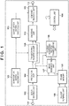
- Fig. 1 is a block diagram showing the configuration of an image encoding apparatus according to the first embodiment.
- the image encoding apparatus includes a control unit 150 configured to control constituent elements to be described below and perform control of the entire apparatus.
- the control unit 150 includes a CPU, a ROM that stores programs to be executed by the CPU, various kinds of parameters, and the like, and a RAM used as the work area of the CPU.
- an OS Operating System
- programs, and parameters stored in the ROM or another nonvolatile storage device may be loaded into the RAM, and after that, the programs may be executed under the control of the OS.
- the image encoding apparatus includes an input terminal 101, a block dividing unit 102, a quantization matrix holding unit 103, a prediction unit 104, a transforming/quantizing unit 105, an inverse quantizing/inverse transforming unit 106, an image regenerating unit 107, a frame memory 108, an in-loop filtering unit 109, an encoding unit 110, a combined encoding unit 111, an output terminal 112, and a quantization matrix encoding unit 113.
- image data (for example, 30 frames/sec) is supplied from an image generation source (not shown) to the input terminal 101 of the apparatus.
- the image generation source can be of any type, as simple examples, an image capturing unit or a video camera, or a hard disk or a storage medium storing encoding target image data can be used.
- the block dividing unit 102 divides image data of one frame input via the input terminal 101 into a plurality of basic blocks and supplies image data of each basic block to the prediction unit 104 of the subsequent stage.
- the quantization matrix holding unit 103 holds a plurality of quantization matrices to be used in quantization processing.
- a method of generating a quantization matrix to be held is not particularly limited.
- a user may input a quantization matrix, a quantization matrix may be calculated from the characteristic of an input image, or a quantization matrix designated in advance as an initial value may be used.
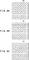
- two-dimensional quantization matrices 801 to 803 corresponding to three types of orthogonal transform (frequency transform) of 8 ⁇ 8 pixels shown in Figs. 8A to 8C are generated and held.
- the prediction unit 104 performs sub-block division for the image data of each basic block, and performs intra-prediction that is prediction in a frame or inter-prediction that is prediction between frames on a sub-block basis, thereby generating predicted image data. Also, the prediction unit 104 calculates prediction error data from the image data and the predicted image data of a sub-block and outputs it. The prediction unit 104 also outputs information necessary for prediction, for example, information of sub-block division, a prediction mode, a motion vector, and the like together with the prediction error. The information necessary for prediction will be referred to as prediction information hereinafter.
- the transforming/quantizing unit 105 performs orthogonal transform (frequency transform) of the prediction error data supplied from the prediction unit 104 on a sub-block basis, thereby obtaining transform coefficients.
- the transforming/quantizing unit 105 then quantizes the transform coefficients of a sub-block of interest using a corresponding quantization matrix held by the quantization matrix holding unit 103 (the transform coefficients after quantization will simply be referred to as "quantized coefficients" hereinafter).
- the inverse quantizing/inverse transforming unit 106 inversely quantizes the quantized coefficients input from the transforming/quantizing unit 105 using a corresponding quantization matrix held by the quantization matrix holding unit 103, thereby regenerating (deriving) the transform coefficients.
- the inverse quantizing/inverse transforming unit 106 also performs inverse orthogonal transform of the transform coefficients, thereby regenerating the prediction error data.
- the image regenerating unit 107 appropriately refers to the frame memory 108 based on the prediction information input from the prediction unit 104, thereby generating predicted image data.
- the image regenerating unit 107 generates regenerated image data from the generated predicted image data and the prediction error data from the inverse quantizing/inverse transforming unit 106, and outputs it to the frame memory 108 again.
- the in-loop filtering unit 109 performs in-loop filtering processing such as deblocking filtering or sample adaptive offsetting for the regenerated image data from the image regenerating unit 107, which is stored in the frame memory 108, and stores the image data after the filtering processing in the frame memory 109 again.
- in-loop filtering processing such as deblocking filtering or sample adaptive offsetting for the regenerated image data from the image regenerating unit 107, which is stored in the frame memory 108, and stores the image data after the filtering processing in the frame memory 109 again.
- the encoding unit 110 encodes the quantized coefficients input from the transforming/quantizing unit 105 and the prediction information input from the prediction unit 104, thereby generating and outputting encoded data.
- the combined encoding unit 111 generates header encoded data using the encoded data of the quantization matrix that is the output from the quantization matrix encoding unit 113. Also, the combined encoding unit 111 forms a bitstream by combining the encoded data of the image input from the encoding unit 110 with the generated header encoded data, and outputs the bitstream to the outside via the output terminal 112.
- the output destination is not particularly limited and may be a storage device such as a recording medium or a file server on a network.
- the three types of quantization matrices 800 to 802 shown in Figs. 8A to 8C are held in a two-dimensional shape.
- the elements in the quantization matrices are not limited to these, as a matter of course. It is also possible to hold a plurality of quantization matrices in correspondence with the same prediction method depending on the size of a sub-block or depending on whether an encoding target is a brightness block or a color difference block.
- a quantization matrix implements quantization processing according to the visual characteristic of a human.
- an element for DC components corresponding to the upper left corner portion of each of the quantization matrices 800 to 802 is small, and an element for an AC component corresponding to the lower right portion is large.
- the quantization matrix encoding unit 113 sequentially reads out the quantization matrices 800 to 802 stored in a two-dimensional shape from the quantization matrix holding unit 106, calculates differences by scanning the elements, and arranges the differences in a one-dimensional matrix.
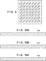
- a scanning method shown in Fig. 9 is used for the quantization matrices 800 to 802 shown in Figs. 8A to 8C , and the difference between each element and an immediately preceding element is calculated in the scanning order.
- the quantization matrix 802 of 8 ⁇ 8 pixels shown in in Fig. 8C is scanned by the scanning method shown in Fig. 9 .
- the difference from a predetermined initial value (for example, "8") is calculated.
- the value is not limited to this, as a matter of course, and the difference from an arbitrary value or the value of the first element itself may be used.
- one-dimensional difference matrices 1000 to 1002 shown in Figs. 10A to 10C are generated using the scanning method shown in Fig. 9 .
- the quantization matrix encoding unit 113 further encodes the difference matrices 1000 to 1002, thereby generating quantization matrix encoded data.
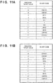
- encoding is performed using an encoding table shown in Fig. 11A .
- the encoding table is not limited to this, and, for example, an encoding table shown in Fig. 11B may be used.
- the thus generated quantization matrix encoded data are output to the combined encoding unit 111 of the subsequent stage.
- the combined encoding unit 111 encodes header information necessary for encoding of image data and combines the encoded data of the quantization matrices 800 to 802. Encoding of image data will be described next.
- the block dividing unit 102 divides image data of one frame input from the input terminal 101 into a plurality of basic blocks and supplies image data of each basic block to the prediction unit 104.
- the size of a basic block is 8 ⁇ 8 pixels, as described above.
- the prediction unit 104 executes prediction processing for the image data of the basic block input from the block dividing unit 102. More specifically, the prediction unit 104 decides a sub-block dividing method of dividing the basic block into finer sub-blocks, and decides a prediction mode such as intra-prediction, inter-prediction, or weighted intra-/inter-prediction on a sub-block basis.
- Figs. 7A to 7F show examples of sub-block division patterns.
- Reference numeral 700 indicating a thick frame on the outer side in each of Figs. 7A to 7F denotes a basic block, which has a size of 8 ⁇ 8 pixels in the embodiment.
- Each rectangle in the thick frame represents a sub-block.
- Fig. 7B shows an example of conventional square sub-block division, and the basic block 700 of 8 ⁇ 8 pixels is divided into four sub-blocks each having a size of 4 ⁇ 4 pixels.
- Figs. 7C to 7F show examples of rectangular sub-block division.
- FIG. 7C shows an example of dividing the basic block 700 into two vertically long sub-blocks each having a size of 4 ⁇ 8 pixels.
- Fig. 7D shows an example of dividing the basic block 700 into two horizontally long sub-blocks each having a size of 8 ⁇ 4 pixels.
- Figs. 7E and 8F show dividing the basic block 700 into three rectangular sub-blocks at a ratio of 1 : 2 : 1. As described above, encoding processing is performed using not only square sub-blocks but also rectangular sub-blocks.
- the sub-block dividing method is not limited to this.
- Quadtree division as shown in Fig. 7B ternary tree division as shown in Fig. 7E or 8F , or binary tree division as shown in Fig. 7C or 7D may be used.
- the quantization matrix holding unit 103 If sub-block division other than that shown in Fig. 7A is used, the quantization matrix holding unit 103 generates a quantization matrix corresponding to the sub-block to be used.
- the generated quantization matrix is encoded by the quantization matrix encoding unit 113.
- a prediction method used in this embodiment will be described anew.
- three types of prediction methods that is, intra-prediction, inter-prediction, and weighted intra-/inter-prediction are used.
- intra-prediction using encoded pixels spatially located around an encoding target block, predicted pixels of the encoding target block are generated, and an intra-prediction mode representing an intra-prediction method such as horizontal prediction, vertical prediction, or DC prediction is also generated.
- inter-prediction using encoded pixels of a frame temporally different from the encoding target block, predicted pixels of the encoding target block are generated, and motion information representing a frame to be referred to, a motion vector, and the like is also generated.
- p[x][y] is a predicted pixel by weighted intra-/inter-prediction for coordinates (x, y) in a block of interest as an encoding target.
- pinter[x][y] represents a pixel value in an inter-prediction image for the coordinates (x, y) in the block of interest.
- pintra[x][y] represents a pixel value in an intra-prediction image for the coordinates (x, y) in the block of interest.
- the weight for the pixel values of inter-prediction increases. If w ⁇ 4, the weight for the pixel values of intra-prediction increases.
- the predicted pixels of the encoding target block are generated in this way, and the intra-prediction mode and motion information used to generate the predicted pixels are also generated.
- the prediction unit 104 generates predicted image data of the encoding target sub-block from the decided prediction mode and encoded pixels. Then, the prediction unit 104 generates prediction error data by calculating the difference between the image data of the encoding target sub-block and the generated predicted image data, and supplies the generated prediction error data to the transforming/quantizing unit 105.
- the prediction unit 104 also supplies prediction information such as sub-block division, a prediction mode (information representing which one of intra-prediction, inter-prediction, and weighted intra-/inter-prediction is used), and vector data to the encoding unit 110 and the image regenerating unit 107.
- the transforming/quantizing unit 105 performs orthogonal transform/quantization for the input prediction error data, thereby generating quantized coefficients. More specifically, the transforming/quantizing unit 105 executes orthogonal transform processing corresponding to the size of the prediction error data, thereby generating orthogonal transform coefficients. Next, the transforming/quantizing unit 105 selects a quantization matrix stored in the quantization matrix holding unit 103 in accordance with the prediction mode and quantizes the orthogonal transform coefficients using the selected quantization matrix, thereby generating quantized coefficients.
- the quantization matrix 800 shown in Fig. 8A is used for a sub-block that has undergone prediction processing by intra-prediction. Also, the quantization matrix 801 shown in Fig.
- the transforming/quantizing unit 105 supplies the generated quantized coefficients to the encoding unit 110 and the inverse quantizing/inverse transforming unit 106.
- the inverse quantizing/inverse transforming unit 106 inversely quantizes the input quantized coefficients of the sub-block using the quantization matrix stored in the quantization matrix holding unit 103, thereby regenerating transform coefficients.
- the inverse quantizing/inverse transforming unit 106 also performs inverse orthogonal transform of the regenerated transform coefficients, thereby regenerating the prediction error data.
- a quantization matrix corresponding to the prediction mode of the encoding target block is used, as in the transforming/quantizing unit 105. More specifically, the same quantization matrix as that used by the transforming/quantizing unit 105 is used.
- the inverse quantizing/inverse transforming unit 106 then supplies the regenerated prediction error data to the image regenerating unit 107.
- the image regenerating unit 107 appropriately refers to the frame memory 108 based on the prediction information input from the prediction unit 104, thereby regenerating predicted image data.
- the image regenerating unit 107 then regenerates the image data of the sub-block by adding the regenerated predicted image and the prediction error data input from the inverse quantizing/inverse transforming unit 106, and stores the image data in the frame memory 108.
- the in-loop filtering unit 109 reads out the regenerated image data from the frame memory 108, and performs in-loop filtering processing such as deblocking filtering. The in-loop filtering unit 109 then stores the image data that has undergone the filtering processing in the frame memory 108 again.
- the encoding unit 110 entropy-encodes the quantized coefficients generated by the transforming/quantizing unit 105 and the prediction information input from the prediction unit 104 on a sub-block basis, thereby generating encoded data.
- the method of entropy encoding is not particularly limited, and Golomb coding, arithmetic coding, Huffman coding, or the like can be used.
- the generated encoded data is supplied to the combined encoding unit 111.
- the combined encoding unit 111 forms a bitstream by multiplexing encoded data input from the encoding unit 110, and the like together with the above-described encoded data of the header. Finally, the bitstream is output from the output terminal 112 to the outside.
- Fig. 6A shows an example of the data structure of a bitstream output in the first embodiment.
- a sequence header includes the encoded data of a quantization matrix, which is formed by the encoded data of each element.
- the position to encode is not limited to this, and the data may be encoded in a picture header portion or another header portion. If the quantization matrix is to be changed in one sequence, the quantization matrix can be updated by newly encoding it. At this time, all quantization matrices may be rewritten, or some of them may be changed by designating the prediction mode of a quantization matrix corresponding to a quantization matrix to be rewritten.
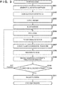
- the quantization matrix holding unit 103 Prior to encoding of an image, in step S301, the quantization matrix holding unit 103 generates two-dimensional quantization matrices and holds them.
- the quantization matrix holding unit 103 according to this embodiment generates the quantization matrices 800 to 802 corresponding to the sub-blocks of 8 ⁇ 8 pixels shown in Figs. 8A to 8C and corresponding to prediction methods including intra-prediction, inter-prediction, and weighted intra-/inter-prediction, and holds these.
- the quantization matrix encoding unit 113 scans the quantization matrices 800 to 802 generated and held in step S301 to calculate the differences between the elements and generates one-dimensional difference matrices.
- the quantization matrix encoding unit 113 according to this embodiment generates the difference matrices 1000 to 1002 shown in Figs. 10A to 10C using the scanning method shown in Fig. 9 from the quantization matrices 800 to 802 shown in Figs. 8A to 8C .
- the quantization matrix encoding unit 113 also generates binary codes from the generated difference matrices 1000 to 1002 by referring to the encoding table shown in Fig. 11A (or Fig. 11B ), thereby generating encoded data.
- step S303 the combined encoding unit 111 generates header information necessary for encoding of the image data together with the generated encoded data of the quantization matrices 800 to 802 and outputs the header information.
- step S304 the block dividing unit 102 divides an input image of each frame into basic blocks.
- step S305 the prediction unit 104 divides the image data of each basic block generated in step S304 into one or more sub-blocks, executes prediction processing for each sub-block, and generates predicted image data and prediction information such as sub-block division information and a prediction mode.
- three types of prediction methods that is, intra-prediction, inter-prediction, and weighted intra-/inter-prediction are used.
- the prediction unit 104 calculates prediction error data that is the difference between the input image data and the predicted image data.
- the prediction unit 104 performs intra-prediction processing for the image data of a sub-block of interest to be encoded by referring to an encoded region of the same frame to which the sub-block of interest belongs, thereby generating intra-prediction image data Pintra[x][y]. Also, the prediction unit 104 performs inter-prediction processing by referring to an already encoded frame (for example, an immediately preceding frame) different from the frame to which the sub-block of interest to be encoded belongs, thereby generating inter-prediction image data Pinter[x][y]. Weighted intra-/inter-prediction image data P[x][y] is then generated based on equation (1) described above.
- the prediction unit 104 obtains the square sums (or the absolute value sums) of the three predicted image data and the difference data between the pixel values of the sub-block of interest, and decides the prediction mode of the predicted image data for which the square sum is minimum as the prediction mode of the sub-block of interest.
- the weight value w is uniquely calculated in accordance with the intra-prediction mode, the size of a motion vector, the position of the sub-block of interest, and the like.
- the calculation method of the weight value w is not limited to this.
- step S306 the transforming/quantizing unit 105 performs orthogonal transform of the prediction error data calculated in step S305, thereby generating transform coefficients. Also, the transforming/quantizing unit 105 selects, based on the prediction information, one of the quantization matrices generated an held in step S301, and performs quantization using the selected quantization matrix, thereby generating quantized coefficients.
- the quantization matrix 800 shown in Fig. 8A is used for a sub-block for which intra-prediction is used
- the quantization matrix 801 shown in Fig. 8B is used for a sub-block for which inter-prediction is used
- the quantization matrix 802 shown in Fig. 8C is used for a sub-block for which weighted intra-/inter-prediction is used.
- step S307 the inverse quantizing/inverse transforming unit 106 inversely quantizes the quantized coefficients generated in step S305 using the quantization matrix generated and held in step S301, thereby regenerating the transform coefficients.
- the inverse quantizing/inverse transforming unit 106 also performs inverse orthogonal transform of the transform coefficients, thereby regenerating the prediction error data.
- the inverse quantization processing is performed using the same quantization matrix as that used in step S306.
- step S308 the image regenerating unit 107 regenerates the predicted image data based on the prediction information generated in step S305.
- the image regenerating unit 107 also regenerates the image data of the sub-block from the regenerated predicted image data and the prediction error data generated in step S307.
- step S309 the encoding unit 110 encodes the prediction information generated in step S305 and the quantized coefficients generated in step S306, thereby generating encoded data.
- the encoding unit 110 also generates a bitstream including other encoded data.
- step S310 the control unit 150 determines whether encoding of all basic blocks in the frame is ended. If encoding is ended, the process advances to step S311. Otherwise, the process returns to step S305 to perform encoding of the next basic block as the target.
- step S311 the in-loop filtering unit 109 performs in-loop filtering processing for the image data regenerated in step S308 to generate the image that has undergone the filtering processing, and the processing is ended.
- steps S304 to S311 are repeated until the final frame to be encoded is input.
- step S306 or a sub-block using weighted intra-/inter-prediction, quantization processing using a quantization matrix dedicated to that is performed. This makes it possible to control quantization for each frequency component and improve subjective image quality.
- quantization matrices are individually defined for the three types of prediction methods including intra-prediction, inter-prediction, and weighted intra-/inter-prediction, and all the three types of quantization matrices are encoded. However, some of these may be shared.
- the sub-block using weighted intra-/inter-prediction may be quantized using the quantization matrix 800 shown in Fig. 8A , like the sub-block using intra-prediction, and encoding of the quantization matrix 802 shown in Fig. 8C may be omitted.
- This can reduce image quality degradation that occurs due to an error such as a block distortion caused by intra-prediction while decreasing the code amount corresponding to the quantization matrix 802 shown in Fig. 8C .
- the sub-block using weighted intra-/inter-prediction may be quantized using the quantization matrix 801 shown in Fig. 8B , like the sub-block using inter-prediction, and encoding of the quantization matrix 802 shown in Fig. 8C may be omitted. This can reduce image quality degradation that occurs due to an error such as an unsmooth motion caused by inter-prediction while decreasing the code amount corresponding to the quantization matrix shown in Fig. 8C .
- a quantization matrix to be used for the sub-block using weighted intra-/inter-prediction may adaptively be decided in accordance with the value of the weight value w representing the weight of an intra-prediction pixel value and an inter-prediction pixel value. For example, if the value of the weight value w for a minimum difference is a predetermined value (for example, a center value of 4) or more, the quantization matrix 801 shown in Fig. 8B may be used for the sub-block using weighted intra-/inter-prediction, and if the value is smaller, the quantization matrix 800 shown in Fig. 8A may be used. This makes it possible to decrease the code amount corresponding to the quantization matrix shown in Fig.
- a quantization matrix to be used for the sub-block using weighted intra-/inter-prediction may newly be generated in accordance with the value of the weight value w.
- QM x y w ⁇ QMinter x y + 8 ⁇ w ⁇ QMintra x y > > 3
- QM[x][y] is an element (quantization step value) at coordinates (x, y) of the calculated quantization matrix used for the sub-block using weighted intra-/inter-prediction.
- QMinter[x][y] is an element at the coordinates (x, y) of the quantization matrix used for the sub-block for inter-prediction.
- QMintra[x][y] is an element at the coordinates (x, y) of the quantization matrix for intra-prediction.
- the quantization matrix for the sub-block using weighted intra-/inter-prediction is uniquely determined.
- the quantization matrix may be made selectable by introducing an identifier.
- quantization matrix encoding for the sub-block using weighted intra-/inter-prediction is made selectable by newly introducing a quantization matrix encoding method information code. For example, if the quantization matrix encoding method information code indicates 0, the quantization matrix 800 ( Fig. 8A ) for the sub-block using intra-prediction is used for the sub-block using weighted intra-/inter-prediction. If the quantization matrix encoding method information code indicates 1, the quantization matrix 801 ( Fig.
- the quantization matrix encoding method information code indicates 2
- the individually encoded quantization matrix 802 ( Fig. 8C ) is used for the sub-block using weighted intra-/inter-prediction. It is therefore possible to selectively implement quantization matrix code amount reduction and unique quantization control for the sub-block using weighted intra-/inter-prediction.
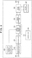
- FIG. 2 is a block diagram showing the configuration of the image decoding apparatus.
- the image decoding apparatus includes a control unit 250 configured to control constituent elements to be described below and perform control of the entire apparatus.
- the control unit 250 includes a CPU, a ROM that stores programs to be executed by the CPU, various kinds of parameters, and the like, and a RAM used as the work area of the CPU.
- an OS Operating System
- programs, and parameters stored in the ROM or another nonvolatile storage device may be loaded into the RAM, and after that, the programs may be executed under the control of the OS.
- the image decoding apparatus includes an input terminal 201, a demultiplexing/decoding unit 202, a decoding unit 203, an inverse quantizing/inverse transforming unit 204, an image regenerating unit 205, a frame memory 206, an in-loop filtering unit 207, an output terminal 208, and a quantization matrix decoding unit 209.
- the image decoding apparatus is configured to input, on a frame basis, a bitstream generated by the above-described image encoding apparatus.
- the demultiplexing/decoding unit 202 inputs an encoded bitstream via the input terminal 201, demultiplexes information concerning decoding processing and encoded data concerning coefficients from the bitstream, and decodes encoded data existing in the header portion of the bitstream.
- the demultiplexing/decoding unit 202 demultiplexes the encoded data of a quantization matrix from the encoded bitstream, and supplies the encoded data to the quantization matrix decoding unit 209.
- the demultiplexing/decoding unit 202 also demultiplexes the encoded data of image data from the encoded bitstream, and supplies the encoded data to the decoding unit 203. In short, the demultiplexing/decoding unit 202 performs an operation reverse to that of the combined encoding unit 111 shown in Fig. 1 .
- the quantization matrix decoding unit 209 decodes the encoded data of the quantization matrix from the demultiplexing/decoding unit 202 and regenerates and holds quantization matrices 800 to 802.
- the inverse quantizing/inverse transforming unit 204 inversely quantizes the quantized coefficients using the regenerated quantization matrices 800 to 802, thereby obtaining transform coefficients.
- the inverse quantizing/inverse transforming unit 204 also performs inverse orthogonal transform, thereby regenerating prediction error data.
- the image regenerating unit 205 appropriately refers to the frame memory 206 based on the input prediction information, thereby generating predicted image data.
- the image regenerating unit 205 generates image data by adding the prediction error data regenerated by the inverse quantizing/inverse transforming unit 204 to the predicted image data, and stores the image data in the frame memory 206.
- a bitstream generated in the first embodiment is input on a frame basis.
- the bitstream of one frame input via the input terminal 201 is supplied to the demultiplexing/decoding unit 202.
- the demultiplexing/decoding unit 202 demultiplexes information concerning decoding processing and encoded data concerning coefficients from the bitstream, and decodes encoded data existing in the header portion of the bitstream. More specifically, the demultiplexing/decoding unit 202 regenerates the encoded data of a quantization matrix.
- the demultiplexing/decoding unit 202 first extracts the encoded data of quantization matrices 800 to 802 shown in Figs. 8A to 8C from the sequence header of the bitstream shown in Fig. 6A , and supplies the encoded data to the quantization matrix decoding unit 209. Next, the demultiplexing/decoding unit 202 regenerates the encoded data of each sub-block of a basic block of picture data, and supplies the encoded data to the decoding unit 203.
- the quantization matrix decoding unit 209 decodes the input quantization matrix encoded data, thereby regenerating one-dimensional difference matrices 1000 to 1002 shown in Figs. 10A to 10C .
- decoding is performed using the encoding table shown in Fig. 11A (or Fig. 11B ), as in the first embodiment.
- the encoding table is not limited to this, and any other encoding table may be used as far as the same encoding table as in the first embodiment is used.
- the quantization matrix decoding unit 209 inversely scans the regenerated one-dimensional difference matrices, thereby regenerating two-dimensional quantization matrices.
- the quantization matrix decoding unit 209 regenerates the three types of quantization matrices 800 to 802 shown in Figs. 8A to 8C from the difference matrices 1000 to 1002 shown in Figs. 10A to 10C using the scanning method shown in Fig. 9 , and holds these.
- the decoding unit 203 decodes the encoded data, thereby regenerating quantized coefficients and prediction information.
- the decoding unit 203 then supplies the regenerated quantized coefficients to the inverse quantizing/inverse transforming unit 204, and supplies the regenerated prediction information to the image regenerating unit 205.
- the inverse quantizing/inverse transforming unit 204 selects one of the quantization matrices 800 to 802 regenerated by the quantization matrix decoding unit 209. The inverse quantizing/inverse transforming unit 204 then inversely quantizes the input quantized coefficients using the selected quantization matrix, thereby generating orthogonal transform coefficients. The inverse quantizing/inverse transforming unit 204 further executes inverse orthogonal transform to regenerate prediction error data and supplies the regenerated prediction information to the image regenerating unit 205.
- the inverse quantizing/inverse transforming unit 204 decides the quantization matrix to be used in inverse quantization processing. That is, the quantization matrix 800 shown in Fig. 8A is selected for a sub-block for which intra-prediction is used, the quantization matrix 801 shown in Fig. 8B is selected for a sub-block for which inter-prediction is used, and the quantization matrix 802 shown in Fig. 8C is selected for a sub-block for which weighted intra-/inter-prediction is used.
- the quantization matrices to be used are not limited to these, and the same quantization matrices as those used by the transforming/quantizing unit 105 and the inverse quantizing/inverse transforming unit 106 according to the first embodiment can be used.
- the image regenerating unit 205 appropriately refers to the frame memory 206 based on the prediction information input from the decoding unit 203, thereby regenerating predicted image data.
- three types of prediction methods that is, intra-prediction, inter-prediction, and weighted intra-/inter-prediction are used, as in the prediction unit 104 according to the first embodiment.
- Detailed prediction processing is the same as that of the prediction unit 104 according to the first embodiment, and a description thereof will be omitted.
- the image regenerating unit 205 regenerates image data by adding the prediction error data input from the inverse quantizing/inverse transforming unit 204 to the predicted image data, and stores the image data in the frame memory 206.
- the stored image data is a prediction referring candidate when decoding another sub-block.
- the in-loop filtering unit 207 reads out the regenerated image data from the frame memory 206, and performs in-loop filtering processing such as deblocking filtering, like the in-loop filtering unit 109 shown in Fig. 1 .
- the in-loop filtering unit 207 then stores the image data that has undergone the filtering processing in the frame memory 206 again.
- the regenerated image stored in the frame memory 206 is finally output from the output terminal 208 to the outside.
- step S401 the demultiplexing/decoding unit 202 demultiplexes information concerning decoding processing and encoded data concerning coefficients from the bitstream, and decodes encoded data in the header portion. More specifically, the encoded data of a quantization matrix is regenerated.
- step S402 the quantization matrix decoding unit 209 decodes the encoded data of the quantization matrix regenerated in step S401, thereby regenerating the one-dimensional difference matrices 1000 to 1002 shown in Figs. 10A to 10C . Also, the quantization matrix decoding unit 209 inversely scans the regenerated one-dimensional difference matrices 1000 to 1002, thereby regenerating and holding the two-dimensional quantization matrices 800 to 802.
- the quantization matrix decoding unit 209 regenerates the three types of quantization matrices 800 to 802 shown in Figs. 8A to 8C from the difference matrices 1000 to 1002 shown in Figs. 10A to 10C using the scanning method shown in Fig. 9 , and holds these.
- step S403 the decoding unit 203 decodes the encoded data demultiplexed in step S401, thereby regenerating quantized coefficients and prediction information.
- step S404 the inverse quantizing/inverse transforming unit 204 obtains transform coefficients by inversely quantizing the quantized coefficients using one of the quantization matrices 800 to 802 regenerated in step S402.
- the inverse quantizing/inverse transforming unit 204 further performs inverse orthogonal transform to regenerate prediction error data.
- the inverse quantizing/inverse transforming unit 204 decides the quantization matrix to be used in accordance with the prediction mode determined based on the prediction information regenerated in step S403. That is, the quantization matrix 800 shown in Fig. 8A is used for a sub-block for which intra-prediction is used. Also, the quantization matrix 801 shown in Fig.
- the quantization matrix 802 shown in Fig. 8C is used for a sub-block for which weighted intra-/inter-prediction is used.
- the quantization matrices to be used are not limited to these, and the same quantization matrices as those used in steps S306 and S307 of the first embodiment can be used.
- step S405 the image regenerating unit 205 regenerates predicted image data from the prediction information generated in step S403.
- the image regenerating unit 205 uses three types of prediction methods, that is, intra-prediction, inter-prediction, and weighted intra-/inter-prediction, as in step S305 of the first embodiment.
- the image regenerating unit 205 also regenerates image data by adding the prediction error data generated in step S404 to the regenerated predicted image data.
- step S406 the control unit 250 determines whether decoding of all basic blocks in the frame is ended. If decoding is ended, the process advances to step S407. Otherwise, the process returns to step S403 to set the next basic block to the decoding target.
- step S407 the in-loop filtering unit 207 performs in-loop filtering processing for the image data regenerated in step S405 to generate the image that has undergone the filtering processing, and the processing is ended.
- quantization matrices are individually defined for the three types of prediction methods including intra-prediction, inter-prediction, and weighted intra-/inter-prediction, and all the three types of quantization matrices are decoded. However, some of these may be shared.
- the sub-block using weighted intra-/inter-prediction may be inversely quantized using the quantization matrix 800 shown in Fig. 8A , like the sub-block using intra-prediction, and decoding of the quantization matrix 802 shown in Fig. 8C may be omitted.
- This makes it possible to decode a bitstream in which image quality degradation that occurs due to an error such as a block distortion caused by intra-prediction is reduced while decreasing the code amount corresponding to the quantization matrix shown in Fig. 8C .
- the sub-block using weighted intra-/inter-prediction may be inversely quantized using the quantization matrix 801 shown in Fig. 8B , like the sub-block using inter-prediction, and decoding of the quantization matrix shown in Fig. 8C may be omitted.
- a quantization matrix to be used for the sub-block using weighted intra-/inter-prediction may adaptively be decided in accordance with the value of a weight value w representing the weight of an intra-prediction pixel value and an inter-prediction pixel value. For example, if the value w is a predetermined value (for example, a center value of 4) or more, Fig. 8(b) may be used for the sub-block using weighted intra-/inter-prediction, and if the value is smaller, the quantization matrix 800 shown in Fig. 8A may be used. This makes it possible to decode a bitstream in which the code amount corresponding to the quantization matrix 802 shown in Fig.
- a quantization matrix to be used for the sub-block using weighted intra-/inter-prediction may newly be generated in accordance with the value of the weight value w, as in equation (2) described above. This makes it possible to perform appropriate quantization control according to the weight value w and decode a bitstream in which subjective image quality is improved while decreasing the code amount corresponding to the quantization matrix 802 shown in Fig. 8C , whose encoding is omitted.
- the quantization matrix for the sub-block using weighted intra-/inter-prediction is uniquely determined.
- the quantization matrix may be made selectable by introducing an identifier.
- quantization matrix encoding for the sub-block using weighted intra-/inter-prediction is made selectable by newly introducing a quantization matrix encoding method information code. For example, if the quantization matrix encoding method information code indicates 0, the quantization matrix 800 ( Fig. 8A ) for the sub-block using intra-prediction is used for the sub-block using weighted intra-/inter-prediction. If the quantization matrix encoding method information code indicates 1, the quantization matrix 801 ( Fig.
- the individually encoded quantization matrix 802 ( Fig. 8C ) is used for the sub-block using weighted intra-/inter-prediction. It is therefore possible to decode a bitstream that selectively implements quantization matrix code amount reduction and unique quantization control for the sub-block using weighted intra-/inter-prediction.
- processing units shown in Figs. 1 and 2 are formed by hardware.
- processing performed by the processing units shown in Figs. 1 and 2 may be configured by a computer program.
- Fig. 5 is a block diagram showing an example of the hardware configuration of a computer applicable as an image display apparatus according to the above-described embodiments.
- a CPU 501 controls the entire computer using computer programs and data stored in a RAM 502 or a ROM 503, and executes processing described above as processing to be performed by the image processing apparatus according to the above-described embodiments. That is, the CPU 501 functions as the processing units shown in Figs. 1 and 2 .
- the RAM 502 has an area for temporarily storing computer programs and data loaded from an external storage device 506 and data acquired from the outside via an I/F (interface) 507.
- the RAM 502 also has a work area used by the CPU 501 to execute various kinds of processing. That is, the RAM 502 can be, for example, allocated as a frame memory or can appropriately provide various kinds of other areas.
- the ROM 503 stores setting data of the computer, a boot program, and the like.
- An operation unit 504 is formed by a keyboard, a mouse, or the like. By operating the operation unit 504, a user of the computer can input various kinds of instructions to the CPU 501.
- a display unit 505 displays a result of processing by the CPU 501.
- the display unit 505 is formed by, for example, a liquid crystal display.
- the external storage device 506 is a mass information storage device represented by a hard disk drive.
- An OS Operating System
- computer programs configured to cause the CPU 501 to implement the functions of the units shown in Figs. 1 and 2 are stored in the external storage device 506.
- Image data as a processing target may also be stored in the external storage device 506.
- the computer programs and data stored in the external storage device 506 are appropriately loaded into the RAM 502 under the control of the CPU 501 and processed by the CPU 501.
- a network such as a LAN or the Internet or another apparatus such as a projection apparatus or a display apparatus can be connected to the I/F 507.
- the computer can acquire or send various kinds of information via the I/F 507.
- Reference numeral 508 denotes a bus that connects the above-described units.
- the CPU 501 executes the boot program in the ROM 503, loads the OS stored in the external storage device 506 into the RAM 502, and activates the OS.
- the apparatus can perform communication via the interface 507 and functions as an information processing apparatus.
- the CPU 501 loads an application (corresponding to Fig. 3 ) concerning image encoding from the external storage device 506 into the RAM 502 and executes the application under the control of the OS
- the CPU 501 functions as various kinds of processing units shown in Fig. 1
- the apparatus functions as an image encoding apparatus.
- the CPU 501 loads an application (corresponding to Fig. 4 ) concerning image decoding from the external storage device 506 into the RAM 502 and executes the application
- the CPU 501 functions as various kinds of processing units shown in Fig. 2
- the apparatus functions as an image decoding apparatus.
- the present invention can be implemented by processing of supplying a program for implementing one or more functions of the above-described embodiments to a system or apparatus via a network or storage medium, and causing one or more processors in the computer of the system or apparatus to read out and execute the program.
- the present invention can also be implemented by a circuit (for example, an ASIC) for implementing one or more functions.
Landscapes
- Engineering & Computer Science (AREA)
- Multimedia (AREA)
- Signal Processing (AREA)
- Compression Or Coding Systems Of Tv Signals (AREA)
- Compression, Expansion, Code Conversion, And Decoders (AREA)
Abstract
Description
- The present invention relates to an image encoding apparatus, an image decoding apparatus, control methods thereof, and a program.
- As an encoding method for moving image compression recording, an HEVC (High Efficiency Video Coding) encoding method (to be referred to as HEVC hereinafter) is known. In the HEVC, to improve the encoding efficiency, a basic block having a size larger than a conventional macro block (16 pixels × 16 pixels) is employed. The basic block with the large size is called a CTU (Coding Tree Unit), and its size is 64 pixels × 64 pixels at maximum. The CTU is further divided into sub-blocks each of which is a unit to perform prediction or transform.
- Also, the HEVC uses processing of adding a weight to coefficients (to be referred to as orthogonal transform coefficients hereinafter) after orthogonal transform, which are called a quantization matrix, based on a frequency component. By further decreasing the data of a high-frequency component whose degradation is unnoticeable to human vision, the compression efficiency can be made high while maintaining image quality.
PTL 1 discloses a technique of encoding such a quantization matrix. - In recent years, actions have been launched to implement international standardization of an encoding method of a higher efficiency as a replacement of the HEVC. JVET (Joint Video Experts Team) was founded between ISO/IEC and ITU-T, and standardization of a VVC (Versatile Video Coding) encoding method (to be referred to as VVC hereinafter) has been promoted. To improve the encoding efficiency, in addition to conventional intra-prediction and inter-prediction, a new prediction method (to be referred to as weighted intra-/inter-prediction hereinafter) using both intra-predicted pixels and inter-predicted pixels has been examined.
- PTL 1:
Japanese Patent Laid-Open No. 2013-38758 - In the VVC as well, introduction of a quantization matrix has been examined, like the HEVC. However, the quantization matrix in the HEVC is based on a conventional prediction method such as intra-prediction or inter-prediction, and does not correspond to weighted intra-/inter-prediction that is a new prediction method. For this reason, quantization control according to a frequency component cannot be performed for an error of weighted intra-/inter-prediction, and subjective image quality cannot be improved.
- The present invention has been made in consideration of the above-described problem, and provides a technique of enabling quantization processing using a quantization matrix corresponding to weighted intra-/inter-prediction and improving subjective image quality.
- In order to solve this problem, for example, an image encoding apparatus according to the present invention has the following configuration. That is, there is provided
an image encoding apparatus for encoding an image, comprising: - prediction means for generating, for a block of interest having a predetermined size as an encoding target in an image, a predicted image from both an intra-prediction image obtained by intra-prediction processing and an inter-prediction image obtained by inter-prediction processing, and obtaining a prediction error that is a difference between the block of interest and the predicted image;
- transform means for frequency-transforming the prediction error obtained by the prediction means;
- quantization means for quantizing, using a quantization matrix, a transform coefficient obtained by the transform means; and
- encoding means for entropy-encoding the transform coefficient after the quantization by the quantization means.
- According to the present invention, it is possible to perform quantization using a quantization matrix even for an error in a new prediction method using both intra-prediction pixels and inter-prediction pixels and improve subjective image quality.
- Other features and advantages of the present invention will be apparent from the following description taken in conjunction with the accompanying drawings. Note that the same reference numerals denote the same or like components throughout the accompanying drawings.
- The accompanying drawings, which are incorporated in and constitute a part of the specification, illustrate embodiments of the invention and, together with the description, serve to explain principles of the invention.
-
Fig. 1 is a block diagram showing the configuration of an image encoding apparatus according to the first embodiment; -
Fig. 2 is a block diagram showing the configuration of an image decoding apparatus according to the second embodiment; -
Fig. 3 is a flowchart showing image encoding processing of the image encoding apparatus according to the first embodiment; -
Fig. 4 is a flowchart showing image decoding processing of the image decoding apparatus according to the second embodiment; -
Fig. 5 is a block diagram showing an example of the hardware configuration of a computer applicable as an image encoding apparatus or a decoding apparatus; -
Fig. 6A is a view showing an example of a bitstream structure generated by the first embodiment; -
Fig. 6B is a view showing an example of a bitstream structure generated by the first embodiment; -
Fig. 7A is a view showing an example of sub-block division used in the embodiment; -
Fig. 7B is a view showing an example of sub-block division used in the embodiment; -
Fig. 7C is a view showing an example of sub-block division used in the embodiment; -
Fig. 7D is a view showing an example of sub-block division used in the embodiment; -
Fig. 7E is a view showing an example of sub-block division used in the embodiment; -
Fig. 7F is a view showing an example of sub-block division used in the embodiment; -
Fig. 8A is a view showing an example of a quantization matrix used in the embodiment; -
Fig. 8B is a view showing an example of a quantization matrix used in the embodiment; -
Fig. 8C is a view showing an example of a quantization matrix used in the embodiment; -
Fig. 9 is a view showing a scanning method of an element of a quantization matrix; -
Fig. 10A is a view showing a difference value matrix of a quantization matrix; -
Fig. 10B is a view showing a difference value matrix of a quantization matrix; -
Fig. 10C is a view showing a difference value matrix of a quantization matrix; -
Fig. 11A is a view showing an example of an encoding table for a quantization matrix; and -
Fig. 11B is a view showing an example of an encoding table for a quantization matrix. - Embodiments according to the present invention will now be described in detail with reference to the accompanying drawings. Note that embodiments to be described below are merely examples, and the present invention is not limited to the illustrated configuration. For example, in the following explanation, terms such as "basic block" and "sub-block" are used. However, the embodiments can be applied to various processing units called "block" and "unit" in an image encoding technique.
-
Fig. 1 is a block diagram showing the configuration of an image encoding apparatus according to the first embodiment. The image encoding apparatus includes acontrol unit 150 configured to control constituent elements to be described below and perform control of the entire apparatus. Thecontrol unit 150 includes a CPU, a ROM that stores programs to be executed by the CPU, various kinds of parameters, and the like, and a RAM used as the work area of the CPU. Note that an OS (Operating System), programs, and parameters stored in the ROM or another nonvolatile storage device may be loaded into the RAM, and after that, the programs may be executed under the control of the OS. - In addition, the image encoding apparatus includes an
input terminal 101, ablock dividing unit 102, a quantizationmatrix holding unit 103, aprediction unit 104, a transforming/quantizing unit 105, an inverse quantizing/inverse transforming unit 106, animage regenerating unit 107, aframe memory 108, an in-loop filtering unit 109, anencoding unit 110, a combinedencoding unit 111, anoutput terminal 112, and a quantizationmatrix encoding unit 113. - In the above-described configuration, image data (for example, 30 frames/sec) is supplied from an image generation source (not shown) to the
input terminal 101 of the apparatus. Note that although the image generation source can be of any type, as simple examples, an image capturing unit or a video camera, or a hard disk or a storage medium storing encoding target image data can be used. - The
block dividing unit 102 divides image data of one frame input via theinput terminal 101 into a plurality of basic blocks and supplies image data of each basic block to theprediction unit 104 of the subsequent stage. - The quantization
matrix holding unit 103 holds a plurality of quantization matrices to be used in quantization processing. A method of generating a quantization matrix to be held is not particularly limited. A user may input a quantization matrix, a quantization matrix may be calculated from the characteristic of an input image, or a quantization matrix designated in advance as an initial value may be used. In this embodiment, two-dimensional quantization matrices 801 to 803 corresponding to three types of orthogonal transform (frequency transform) of 8 × 8 pixels shown inFigs. 8A to 8C are generated and held. - The
prediction unit 104 performs sub-block division for the image data of each basic block, and performs intra-prediction that is prediction in a frame or inter-prediction that is prediction between frames on a sub-block basis, thereby generating predicted image data. Also, theprediction unit 104 calculates prediction error data from the image data and the predicted image data of a sub-block and outputs it. Theprediction unit 104 also outputs information necessary for prediction, for example, information of sub-block division, a prediction mode, a motion vector, and the like together with the prediction error. The information necessary for prediction will be referred to as prediction information hereinafter. - The transforming/
quantizing unit 105 performs orthogonal transform (frequency transform) of the prediction error data supplied from theprediction unit 104 on a sub-block basis, thereby obtaining transform coefficients. The transforming/quantizing unit 105 then quantizes the transform coefficients of a sub-block of interest using a corresponding quantization matrix held by the quantization matrix holding unit 103 (the transform coefficients after quantization will simply be referred to as "quantized coefficients" hereinafter). - The inverse quantizing/
inverse transforming unit 106 inversely quantizes the quantized coefficients input from the transforming/quantizing unit 105 using a corresponding quantization matrix held by the quantizationmatrix holding unit 103, thereby regenerating (deriving) the transform coefficients. The inverse quantizing/inverse transforming unit 106 also performs inverse orthogonal transform of the transform coefficients, thereby regenerating the prediction error data. - The
image regenerating unit 107 appropriately refers to theframe memory 108 based on the prediction information input from theprediction unit 104, thereby generating predicted image data. Theimage regenerating unit 107 generates regenerated image data from the generated predicted image data and the prediction error data from the inverse quantizing/inverse transforming unit 106, and outputs it to theframe memory 108 again. - The in-
loop filtering unit 109 performs in-loop filtering processing such as deblocking filtering or sample adaptive offsetting for the regenerated image data from theimage regenerating unit 107, which is stored in theframe memory 108, and stores the image data after the filtering processing in theframe memory 109 again. - The
encoding unit 110 encodes the quantized coefficients input from the transforming/quantizing unit 105 and the prediction information input from theprediction unit 104, thereby generating and outputting encoded data. - The quantization
matrix encoding unit 113 encodes a quantization matrix input from the quantizationmatrix holding unit 103, thereby generating and outputting encoded data of the quantization matrix. - The combined
encoding unit 111 generates header encoded data using the encoded data of the quantization matrix that is the output from the quantizationmatrix encoding unit 113. Also, the combinedencoding unit 111 forms a bitstream by combining the encoded data of the image input from theencoding unit 110 with the generated header encoded data, and outputs the bitstream to the outside via theoutput terminal 112. - Note that the output destination is not particularly limited and may be a storage device such as a recording medium or a file server on a network.
- An image encoding operation of the image encoding apparatus according to the embodiment will be described below in more detail.
- First, the quantization
matrix holding unit 103 generates a quantization matrix. The quantization matrix is generated in accordance with the size of a sub-block to be encoded or the type of the prediction method. In this embodiment, a quantization matrix having a size of 8 × 8 pixels corresponding to abasic block 700 of 8 × 8 pixels shown inFig. 7A is generated. However, the quantization matrix to be generated is not limited to this, and a quantization matrix having a size of 4 × 8 pixels, 8 × 4 pixels, or 4 × 4 pixels corresponding to the shape of a sub-block may be generated. A method of deciding each element of a quantization matrix is not particularly limited. For example, a predetermined initial value may be used, or elements may individually be set. Alternatively, the elements may be generated in accordance with the characteristic of an image. - The quantization
matrix holding unit 103 holds the thus generated quantization matrix. InFigs. 8A to 8C ,reference numerals 800 to 802 denote quantization matrices generated and held by the quantizationmatrix holding unit 103 according to the embodiment. Thequantization matrix 800 shown inFig. 8A represents a quantization matrix used for intra-prediction. Thequantization matrix 801 shown inFig. 8B represents a quantization matrix used for inter-prediction. Thequantization matrix 802 shown inFig. 8C represents a quantization matrix corresponding to weighted intra-/inter-prediction. Each of thequantization matrices 800 to 802 is formed by 8 × 8 elements (quantization step values), as shown inFigs. 8A to 8C . In this embodiment, the three types ofquantization matrices 800 to 802 shown inFigs. 8A to 8C are held in a two-dimensional shape. However, the elements in the quantization matrices are not limited to these, as a matter of course. It is also possible to hold a plurality of quantization matrices in correspondence with the same prediction method depending on the size of a sub-block or depending on whether an encoding target is a brightness block or a color difference block. In general, a quantization matrix implements quantization processing according to the visual characteristic of a human. Hence, as shown inFigs. 8A to 8C , an element for DC components corresponding to the upper left corner portion of each of thequantization matrices 800 to 802 is small, and an element for an AC component corresponding to the lower right portion is large. - The quantization
matrix encoding unit 113 sequentially reads out thequantization matrices 800 to 802 stored in a two-dimensional shape from the quantizationmatrix holding unit 106, calculates differences by scanning the elements, and arranges the differences in a one-dimensional matrix. In this embodiment, a scanning method shown inFig. 9 is used for thequantization matrices 800 to 802 shown inFigs. 8A to 8C , and the difference between each element and an immediately preceding element is calculated in the scanning order. For example, thequantization matrix 802 of 8 × 8 pixels shown in inFig. 8C is scanned by the scanning method shown inFig. 9 . Next to the first element "8" located at the upper left corner, an element "11" located immediately under that is scanned, and the difference "+3" is calculated. To encode the first element ("8" in this embodiment) of thequantization matrix 802, the difference from a predetermined initial value (for example, "8") is calculated. However, the value is not limited to this, as a matter of course, and the difference from an arbitrary value or the value of the first element itself may be used. - As described above, in this embodiment, from the
quantization matrices 800 to 802 shown inFigs. 8A to 8C , one-dimensional difference matrices 1000 to 1002 shown inFigs. 10A to 10C are generated using the scanning method shown inFig. 9 . The quantizationmatrix encoding unit 113 further encodes thedifference matrices 1000 to 1002, thereby generating quantization matrix encoded data. In this embodiment, encoding is performed using an encoding table shown inFig. 11A . However, the encoding table is not limited to this, and, for example, an encoding table shown inFig. 11B may be used. The thus generated quantization matrix encoded data are output to the combinedencoding unit 111 of the subsequent stage. - Referring back to
Fig. 1 , the combinedencoding unit 111 encodes header information necessary for encoding of image data and combines the encoded data of thequantization matrices 800 to 802. Encoding of image data will be described next. - The
block dividing unit 102 divides image data of one frame input from theinput terminal 101 into a plurality of basic blocks and supplies image data of each basic block to theprediction unit 104. In this embodiment, the size of a basic block is 8 × 8 pixels, as described above. - The
prediction unit 104 executes prediction processing for the image data of the basic block input from theblock dividing unit 102. More specifically, theprediction unit 104 decides a sub-block dividing method of dividing the basic block into finer sub-blocks, and decides a prediction mode such as intra-prediction, inter-prediction, or weighted intra-/inter-prediction on a sub-block basis. -
Figs. 7A to 7F show examples of sub-block division patterns.Reference numeral 700 indicating a thick frame on the outer side in each ofFigs. 7A to 7F denotes a basic block, which has a size of 8 × 8 pixels in the embodiment. Each rectangle in the thick frame represents a sub-block.Fig. 7A shows an example of basic block = sub-block.Fig. 7B shows an example of conventional square sub-block division, and thebasic block 700 of 8 × 8 pixels is divided into four sub-blocks each having a size of 4 × 4 pixels. On the other hand,Figs. 7C to 7F show examples of rectangular sub-block division.Fig. 7C shows an example of dividing thebasic block 700 into two vertically long sub-blocks each having a size of 4 × 8 pixels.Fig. 7D shows an example of dividing thebasic block 700 into two horizontally long sub-blocks each having a size of 8 × 4 pixels.Figs. 7E and8F show dividing thebasic block 700 into three rectangular sub-blocks at a ratio of 1 : 2 : 1. As described above, encoding processing is performed using not only square sub-blocks but also rectangular sub-blocks. - In this embodiment, only the method (
Fig. 7A ) in which the basic block of 8 × 8 pixels is not divided is used, as described above. However, the sub-block dividing method is not limited to this. Quadtree division as shown inFig. 7B , ternary tree division as shown inFig. 7E or8F , or binary tree division as shown inFig. 7C or7D may be used. If sub-block division other than that shown inFig. 7A is used, the quantizationmatrix holding unit 103 generates a quantization matrix corresponding to the sub-block to be used. The generated quantization matrix is encoded by the quantizationmatrix encoding unit 113. - A prediction method used in this embodiment will be described anew. In this embodiments, three types of prediction methods, that is, intra-prediction, inter-prediction, and weighted intra-/inter-prediction are used. In intra-prediction, using encoded pixels spatially located around an encoding target block, predicted pixels of the encoding target block are generated, and an intra-prediction mode representing an intra-prediction method such as horizontal prediction, vertical prediction, or DC prediction is also generated. In inter-prediction, using encoded pixels of a frame temporally different from the encoding target block, predicted pixels of the encoding target block are generated, and motion information representing a frame to be referred to, a motion vector, and the like is also generated.
- In weighted intra-/inter-prediction, predicted pixels of the encoding target block are generated by obtaining the weighted average of the pixel values generated by the above-described intra-prediction and the pixel values generated by the above-described inter-prediction. For example, calculation is performed using

- In equation (1), p[x][y] is a predicted pixel by weighted intra-/inter-prediction for coordinates (x, y) in a block of interest as an encoding target.
Also, pinter[x][y] represents a pixel value in an inter-prediction image for the coordinates (x, y) in the block of interest. In addition, pintra[x][y] represents a pixel value in an intra-prediction image for the coordinates (x, y) in the block of interest. w represents a weight value for the pixel values of inter-prediction and the pixel values of intra-prediction. In this embodiment, when w = 4, weights for the pixel values of inter-prediction and the pixel values of intra-prediction become equal. In other words, if w > 4, the weight for the pixel values of inter-prediction increases. If w < 4, the weight for the pixel values of intra-prediction increases. In weighted intra-/inter-prediction, the predicted pixels of the encoding target block are generated in this way, and the intra-prediction mode and motion information used to generate the predicted pixels are also generated. - The
prediction unit 104 generates predicted image data of the encoding target sub-block from the decided prediction mode and encoded pixels. Then, theprediction unit 104 generates prediction error data by calculating the difference between the image data of the encoding target sub-block and the generated predicted image data, and supplies the generated prediction error data to the transforming/quantizing unit 105. Theprediction unit 104 also supplies prediction information such as sub-block division, a prediction mode (information representing which one of intra-prediction, inter-prediction, and weighted intra-/inter-prediction is used), and vector data to theencoding unit 110 and theimage regenerating unit 107. - The transforming/
quantizing unit 105 performs orthogonal transform/quantization for the input prediction error data, thereby generating quantized coefficients. More specifically, the transforming/quantizing unit 105 executes orthogonal transform processing corresponding to the size of the prediction error data, thereby generating orthogonal transform coefficients.
Next, the transforming/quantizing unit 105 selects a quantization matrix stored in the quantizationmatrix holding unit 103 in accordance with the prediction mode and quantizes the orthogonal transform coefficients using the selected quantization matrix, thereby generating quantized coefficients. In this embodiment, thequantization matrix 800 shown inFig. 8A is used for a sub-block that has undergone prediction processing by intra-prediction. Also, thequantization matrix 801 shown inFig. 8B is used for a sub-block that has undergone inter-prediction. Thequantization matrix 802 shown inFig. 8C is used for a sub-block that has undergone weighted intra-/inter-prediction. However, the quantization matrices to be used are not limited to these. Then, the transforming/quantizing unit 105 supplies the generated quantized coefficients to theencoding unit 110 and the inverse quantizing/inverse transforming unit 106. - The inverse quantizing/
inverse transforming unit 106 inversely quantizes the input quantized coefficients of the sub-block using the quantization matrix stored in the quantizationmatrix holding unit 103, thereby regenerating transform coefficients. The inverse quantizing/inverse transforming unit 106 also performs inverse orthogonal transform of the regenerated transform coefficients, thereby regenerating the prediction error data. For the inverse quantization processing, a quantization matrix corresponding to the prediction mode of the encoding target block is used, as in the transforming/quantizing unit 105. More specifically, the same quantization matrix as that used by the transforming/quantizing unit 105 is used. The inverse quantizing/inverse transforming unit 106 then supplies the regenerated prediction error data to theimage regenerating unit 107. - The
image regenerating unit 107 appropriately refers to theframe memory 108 based on the prediction information input from theprediction unit 104, thereby regenerating predicted image data. Theimage regenerating unit 107 then regenerates the image data of the sub-block by adding the regenerated predicted image and the prediction error data input from the inverse quantizing/inverse transforming unit 106, and stores the image data in theframe memory 108. - The in-
loop filtering unit 109 reads out the regenerated image data from theframe memory 108, and performs in-loop filtering processing such as deblocking filtering. The in-loop filtering unit 109 then stores the image data that has undergone the filtering processing in theframe memory 108 again. - The
encoding unit 110 entropy-encodes the quantized coefficients generated by the transforming/quantizing unit 105 and the prediction information input from theprediction unit 104 on a sub-block basis, thereby generating encoded data. The method of entropy encoding is not particularly limited, and Golomb coding, arithmetic coding, Huffman coding, or the like can be used. The generated encoded data is supplied to the combinedencoding unit 111. - The combined
encoding unit 111 forms a bitstream by multiplexing encoded data input from theencoding unit 110, and the like together with the above-described encoded data of the header. Finally, the bitstream is output from theoutput terminal 112 to the outside. -
Fig. 6A shows an example of the data structure of a bitstream output in the first embodiment. A sequence header includes the encoded data of a quantization matrix, which is formed by the encoded data of each element. However, the position to encode is not limited to this, and the data may be encoded in a picture header portion or another header portion. If the quantization matrix is to be changed in one sequence, the quantization matrix can be updated by newly encoding it. At this time, all quantization matrices may be rewritten, or some of them may be changed by designating the prediction mode of a quantization matrix corresponding to a quantization matrix to be rewritten. - The processing procedure of encoding processing of one frame by the image encoding apparatus according to the first embodiment will be described below with reference to the flowchart of
Fig. 3 . Note that the processing of each step in the following description is executed by its main subject under the control of thecontrol unit 150. - First, prior to encoding of an image, in step S301, the quantization
matrix holding unit 103 generates two-dimensional quantization matrices and holds them. The quantizationmatrix holding unit 103 according to this embodiment generates thequantization matrices 800 to 802 corresponding to the sub-blocks of 8 × 8 pixels shown inFigs. 8A to 8C and corresponding to prediction methods including intra-prediction, inter-prediction, and weighted intra-/inter-prediction, and holds these. - In step S302, the quantization
matrix encoding unit 113 scans thequantization matrices 800 to 802 generated and held in step S301 to calculate the differences between the elements and generates one-dimensional difference matrices. The quantizationmatrix encoding unit 113 according to this embodiment generates thedifference matrices 1000 to 1002 shown inFigs. 10A to 10C using the scanning method shown inFig. 9 from thequantization matrices 800 to 802 shown inFigs. 8A to 8C . The quantizationmatrix encoding unit 113 also generates binary codes from the generateddifference matrices 1000 to 1002 by referring to the encoding table shown inFig. 11A (or Fig. 11B ), thereby generating encoded data. - In step S303, the combined
encoding unit 111 generates header information necessary for encoding of the image data together with the generated encoded data of thequantization matrices 800 to 802 and outputs the header information. - In step S304, the
block dividing unit 102 divides an input image of each frame into basic blocks. In step S305, theprediction unit 104 divides the image data of each basic block generated in step S304 into one or more sub-blocks, executes prediction processing for each sub-block, and generates predicted image data and prediction information such as sub-block division information and a prediction mode. In this embodiment, three types of prediction methods, that is, intra-prediction, inter-prediction, and weighted intra-/inter-prediction are used. Also, theprediction unit 104 calculates prediction error data that is the difference between the input image data and the predicted image data. - Note that a detailed example of processing by the
prediction unit 104 is as follows. Theprediction unit 104 performs intra-prediction processing for the image data of a sub-block of interest to be encoded by referring to an encoded region of the same frame to which the sub-block of interest belongs, thereby generating intra-prediction image data Pintra[x][y]. Also, theprediction unit 104 performs inter-prediction processing by referring to an already encoded frame (for example, an immediately preceding frame) different from the frame to which the sub-block of interest to be encoded belongs, thereby generating inter-prediction image data Pinter[x][y]. Weighted intra-/inter-prediction image data P[x][y] is then generated based on equation (1) described above. Theprediction unit 104 obtains the square sums (or the absolute value sums) of the three predicted image data and the difference data between the pixel values of the sub-block of interest, and decides the prediction mode of the predicted image data for which the square sum is minimum as the prediction mode of the sub-block of interest. In this embodiment, the weight value w is uniquely calculated in accordance with the intra-prediction mode, the size of a motion vector, the position of the sub-block of interest, and the like. However, the calculation method of the weight value w is not limited to this. For example, theprediction unit 104 sets w = 0, 1,..., 8 and obtains nine predicted image data in these cases. Theprediction unit 104 may obtain the square sums (or the absolute value sums) of the nine predicted image data and the difference data between the pixel values of the sub-block of interest, and may determine "w" for which the square sum is minimum. In this case, if w = 0, theprediction unit 104 decides, from equation (1), that the sub-block of interest should be encoded by intra-prediction encoding. If w = 8, theprediction unit 104 decides, from equation (1), that the sub-block of interest should be encoded by inter-prediction encoding. If w ranges from 1 to 7, theprediction unit 104 decides that the sub-block of interest should be encoded by weighted intra-/inter-prediction encoding. In this case, the decided value w may also be encoded in step S309 of the subsequent stage. - In step S306, the transforming/
quantizing unit 105 performs orthogonal transform of the prediction error data calculated in step S305, thereby generating transform coefficients. Also, the transforming/quantizing unit 105 selects, based on the prediction information, one of the quantization matrices generated an held in step S301, and performs quantization using the selected quantization matrix, thereby generating quantized coefficients. In this embodiment, thequantization matrix 800 shown inFig. 8A is used for a sub-block for which intra-prediction is used, thequantization matrix 801 shown inFig. 8B is used for a sub-block for which inter-prediction is used, and thequantization matrix 802 shown inFig. 8C is used for a sub-block for which weighted intra-/inter-prediction is used. - In step S307, the inverse quantizing/
inverse transforming unit 106 inversely quantizes the quantized coefficients generated in step S305 using the quantization matrix generated and held in step S301, thereby regenerating the transform coefficients. The inverse quantizing/inverse transforming unit 106 also performs inverse orthogonal transform of the transform coefficients, thereby regenerating the prediction error data. In this step, the inverse quantization processing is performed using the same quantization matrix as that used in step S306. - In step S308, the
image regenerating unit 107 regenerates the predicted image data based on the prediction information generated in step S305. Theimage regenerating unit 107 also regenerates the image data of the sub-block from the regenerated predicted image data and the prediction error data generated in step S307. - In step S309, the
encoding unit 110 encodes the prediction information generated in step S305 and the quantized coefficients generated in step S306, thereby generating encoded data. Theencoding unit 110 also generates a bitstream including other encoded data. - In step S310, the
control unit 150 determines whether encoding of all basic blocks in the frame is ended. If encoding is ended, the process advances to step S311. Otherwise, the process returns to step S305 to perform encoding of the next basic block as the target. - In step S311, the in-
loop filtering unit 109 performs in-loop filtering processing for the image data regenerated in step S308 to generate the image that has undergone the filtering processing, and the processing is ended. - In the above-described processing, to encode the second and subsequent frames of the moving image, steps S304 to S311 are repeated until the final frame to be encoded is input.
- With the above-described configuration and operation, particularly in step S306, or a sub-block using weighted intra-/inter-prediction, quantization processing using a quantization matrix dedicated to that is performed. This makes it possible to control quantization for each frequency component and improve subjective image quality.
- Note that in this embodiment, quantization matrices are individually defined for the three types of prediction methods including intra-prediction, inter-prediction, and weighted intra-/inter-prediction, and all the three types of quantization matrices are encoded. However, some of these may be shared.
- For example, the sub-block using weighted intra-/inter-prediction may be quantized using the
quantization matrix 800 shown inFig. 8A , like the sub-block using intra-prediction, and encoding of thequantization matrix 802 shown inFig. 8C may be omitted. This can reduce image quality degradation that occurs due to an error such as a block distortion caused by intra-prediction while decreasing the code amount corresponding to thequantization matrix 802 shown inFig. 8C . - Similarly, the sub-block using weighted intra-/inter-prediction may be quantized using the
quantization matrix 801 shown inFig. 8B , like the sub-block using inter-prediction, and encoding of thequantization matrix 802 shown inFig. 8C may be omitted. This can reduce image quality degradation that occurs due to an error such as an unsmooth motion caused by inter-prediction while decreasing the code amount corresponding to the quantization matrix shown inFig. 8C . - Alternatively, in equation (1) described above, a quantization matrix to be used for the sub-block using weighted intra-/inter-prediction may adaptively be decided in accordance with the value of the weight value w representing the weight of an intra-prediction pixel value and an inter-prediction pixel value. For example, if the value of the weight value w for a minimum difference is a predetermined value (for example, a center value of 4) or more, the
quantization matrix 801 shown inFig. 8B may be used for the sub-block using weighted intra-/inter-prediction, and if the value is smaller, thequantization matrix 800 shown inFig. 8A may be used. This makes it possible to decrease the code amount corresponding to the quantization matrix shown inFig. 8C , whose encoding is omitted while reducing image quality degradation for the prediction method with the larger weight. Alternatively, a quantization matrix to be used for the sub-block using weighted intra-/inter-prediction may newly be generated in accordance with the value of the weight value w. For example, calculation can be performed using
quantization matrix 802 shown inFig. 8C , whose encoding is omitted. - Also, in this embodiment, the quantization matrix for the sub-block using weighted intra-/inter-prediction is uniquely determined. However, the quantization matrix may be made selectable by introducing an identifier. For example, in
Fig. 6B , quantization matrix encoding for the sub-block using weighted intra-/inter-prediction is made selectable by newly introducing a quantization matrix encoding method information code. For example, if the quantization matrix encoding method information code indicates 0, the quantization matrix 800 (Fig. 8A ) for the sub-block using intra-prediction is used for the sub-block using weighted intra-/inter-prediction. If the quantization matrix encoding method information code indicates 1, the quantization matrix 801 (Fig. 8B ) for the sub-block using inter-prediction is used for the sub-block using weighted intra-/inter-prediction. On the other hand, if the quantization matrix encoding method information code indicates 2, the individually encoded quantization matrix 802 (Fig. 8C ) is used for the sub-block using weighted intra-/inter-prediction. It is therefore possible to selectively implement quantization matrix code amount reduction and unique quantization control for the sub-block using weighted intra-/inter-prediction. - In the second embodiment, an image decoding apparatus for decoding encoded data generated by the image encoding apparatus according to the first embodiment will be described.
Fig. 2 is a block diagram showing the configuration of the image decoding apparatus. - The image decoding apparatus includes a
control unit 250 configured to control constituent elements to be described below and perform control of the entire apparatus. Thecontrol unit 250 includes a CPU, a ROM that stores programs to be executed by the CPU, various kinds of parameters, and the like, and a RAM used as the work area of the CPU. Note that an OS (Operating System), programs, and parameters stored in the ROM or another nonvolatile storage device may be loaded into the RAM, and after that, the programs may be executed under the control of the OS. - In addition, the image decoding apparatus includes an
input terminal 201, a demultiplexing/decoding unit 202, adecoding unit 203, an inverse quantizing/inverse transforming unit 204, animage regenerating unit 205, aframe memory 206, an in-loop filtering unit 207, anoutput terminal 208, and a quantizationmatrix decoding unit 209. - The configuration and operation of the image decoding apparatus in the configuration of the above-described image decoding apparatus will be described below. Note that the image decoding apparatus is configured to input, on a frame basis, a bitstream generated by the above-described image encoding apparatus.
- The demultiplexing/
decoding unit 202 inputs an encoded bitstream via theinput terminal 201, demultiplexes information concerning decoding processing and encoded data concerning coefficients from the bitstream, and decodes encoded data existing in the header portion of the bitstream. The demultiplexing/decoding unit 202 according to this embodiment demultiplexes the encoded data of a quantization matrix from the encoded bitstream, and supplies the encoded data to the quantizationmatrix decoding unit 209. The demultiplexing/decoding unit 202 also demultiplexes the encoded data of image data from the encoded bitstream, and supplies the encoded data to thedecoding unit 203. In short, the demultiplexing/decoding unit 202 performs an operation reverse to that of the combinedencoding unit 111 shown inFig. 1 . - The quantization
matrix decoding unit 209 decodes the encoded data of the quantization matrix from the demultiplexing/decoding unit 202 and regenerates and holdsquantization matrices 800 to 802. - The
decoding unit 203 decodes the encoded data input from the demultiplexing/decoding unit 202 and regenerates quantized coefficients and prediction information. - Like the inverse quantizing/
inverse transforming unit 106 shown inFig. 1 , the inverse quantizing/inverse transforming unit 204 inversely quantizes the quantized coefficients using the regeneratedquantization matrices 800 to 802, thereby obtaining transform coefficients. The inverse quantizing/inverse transforming unit 204 also performs inverse orthogonal transform, thereby regenerating prediction error data. - The
image regenerating unit 205 appropriately refers to theframe memory 206 based on the input prediction information, thereby generating predicted image data. Theimage regenerating unit 205 generates image data by adding the prediction error data regenerated by the inverse quantizing/inverse transforming unit 204 to the predicted image data, and stores the image data in theframe memory 206. - The in-
loop filtering unit 207 performs in-loop filtering processing such as deblocking filtering for the regenerated image stored in theframe memory 206, and stores the image data that has undergone the filtering processing in theframe memory 206 again, like the in-loop filtering unit 109 shown inFig. 1 . Then, theoutput terminal 208 outputs the regenerated image data to an external apparatus (for example, a display apparatus). - The operation of each constituent element of the image decoding apparatus shown in
Fig. 2 will be described next in more detail. - In the second embodiment, a bitstream generated in the first embodiment is input on a frame basis.
- The bitstream of one frame input via the
input terminal 201 is supplied to the demultiplexing/decoding unit 202. The demultiplexing/decoding unit 202 demultiplexes information concerning decoding processing and encoded data concerning coefficients from the bitstream, and decodes encoded data existing in the header portion of the bitstream. More specifically, the demultiplexing/decoding unit 202 regenerates the encoded data of a quantization matrix. The demultiplexing/decoding unit 202 according to this embodiment first extracts the encoded data ofquantization matrices 800 to 802 shown inFigs. 8A to 8C from the sequence header of the bitstream shown inFig. 6A , and supplies the encoded data to the quantizationmatrix decoding unit 209. Next, the demultiplexing/decoding unit 202 regenerates the encoded data of each sub-block of a basic block of picture data, and supplies the encoded data to thedecoding unit 203. - First, the quantization
matrix decoding unit 209 decodes the input quantization matrix encoded data, thereby regenerating one-dimensional difference matrices 1000 to 1002 shown inFigs. 10A to 10C . In this embodiment, decoding is performed using the encoding table shown inFig. 11A (or Fig. 11B ), as in the first embodiment. However, the encoding table is not limited to this, and any other encoding table may be used as far as the same encoding table as in the first embodiment is used. Also, the quantizationmatrix decoding unit 209 inversely scans the regenerated one-dimensional difference matrices, thereby regenerating two-dimensional quantization matrices. Here, an operation reverse to that of the quantizationmatrix encoding unit 113 according to the first embodiment is performed. That is, the quantizationmatrix decoding unit 209 according to this embodiment regenerates the three types ofquantization matrices 800 to 802 shown inFigs. 8A to 8C from thedifference matrices 1000 to 1002 shown inFigs. 10A to 10C using the scanning method shown inFig. 9 , and holds these. - The
decoding unit 203 decodes the encoded data, thereby regenerating quantized coefficients and prediction information. Thedecoding unit 203 then supplies the regenerated quantized coefficients to the inverse quantizing/inverse transforming unit 204, and supplies the regenerated prediction information to theimage regenerating unit 205. - The inverse quantizing/
inverse transforming unit 204 selects one of thequantization matrices 800 to 802 regenerated by the quantizationmatrix decoding unit 209. The inverse quantizing/inverse transforming unit 204 then inversely quantizes the input quantized coefficients using the selected quantization matrix, thereby generating orthogonal transform coefficients. The inverse quantizing/inverse transforming unit 204 further executes inverse orthogonal transform to regenerate prediction error data and supplies the regenerated prediction information to theimage regenerating unit 205. In accordance with the prediction mode of a decoding target block determined in accordance with the prediction information regenerated by thedecoding unit 203, the inverse quantizing/inverse transforming unit 204 according to this embodiment decides the quantization matrix to be used in inverse quantization processing. That is, thequantization matrix 800 shown inFig. 8A is selected for a sub-block for which intra-prediction is used, thequantization matrix 801 shown inFig. 8B is selected for a sub-block for which inter-prediction is used, and thequantization matrix 802 shown inFig. 8C is selected for a sub-block for which weighted intra-/inter-prediction is used. However, the quantization matrices to be used are not limited to these, and the same quantization matrices as those used by the transforming/quantizing unit 105 and the inverse quantizing/inverse transforming unit 106 according to the first embodiment can be used. - The
image regenerating unit 205 appropriately refers to theframe memory 206 based on the prediction information input from thedecoding unit 203, thereby regenerating predicted image data. In this embodiment, three types of prediction methods, that is, intra-prediction, inter-prediction, and weighted intra-/inter-prediction are used, as in theprediction unit 104 according to the first embodiment. Detailed prediction processing is the same as that of theprediction unit 104 according to the first embodiment, and a description thereof will be omitted. Theimage regenerating unit 205 regenerates image data by adding the prediction error data input from the inverse quantizing/inverse transforming unit 204 to the predicted image data, and stores the image data in theframe memory 206. The stored image data is a prediction referring candidate when decoding another sub-block. - The in-
loop filtering unit 207 reads out the regenerated image data from theframe memory 206, and performs in-loop filtering processing such as deblocking filtering, like the in-loop filtering unit 109 shown inFig. 1 . The in-loop filtering unit 207 then stores the image data that has undergone the filtering processing in theframe memory 206 again. - The regenerated image stored in the
frame memory 206 is finally output from theoutput terminal 208 to the outside. - The processing procedure of decoding processing of one frame by the image decoding apparatus according to the second embodiment will be described below with reference to the flowchart of
Fig. 4 . Note that the processing of each step in the following description is executed by its main subject under the control of thecontrol unit 250. - First, in step S401, the demultiplexing/
decoding unit 202 demultiplexes information concerning decoding processing and encoded data concerning coefficients from the bitstream, and decodes encoded data in the header portion. More specifically, the encoded data of a quantization matrix is regenerated. - In step S402, the quantization
matrix decoding unit 209 decodes the encoded data of the quantization matrix regenerated in step S401, thereby regenerating the one-dimensional difference matrices 1000 to 1002 shown inFigs. 10A to 10C . Also, the quantizationmatrix decoding unit 209 inversely scans the regenerated one-dimensional difference matrices 1000 to 1002, thereby regenerating and holding the two-dimensional quantization matrices 800 to 802. - That is, in this embodiment, the quantization
matrix decoding unit 209 regenerates the three types ofquantization matrices 800 to 802 shown inFigs. 8A to 8C from thedifference matrices 1000 to 1002 shown inFigs. 10A to 10C using the scanning method shown inFig. 9 , and holds these. - In step S403, the
decoding unit 203 decodes the encoded data demultiplexed in step S401, thereby regenerating quantized coefficients and prediction information. - In step S404, the inverse quantizing/
inverse transforming unit 204 obtains transform coefficients by inversely quantizing the quantized coefficients using one of thequantization matrices 800 to 802 regenerated in step S402. The inverse quantizing/inverse transforming unit 204 further performs inverse orthogonal transform to regenerate prediction error data. The inverse quantizing/inverse transforming unit 204 according to this embodiment decides the quantization matrix to be used in accordance with the prediction mode determined based on the prediction information regenerated in step S403. That is, thequantization matrix 800 shown inFig. 8A is used for a sub-block for which intra-prediction is used. Also, thequantization matrix 801 shown inFig. 8B is used for a sub-block for which inter-prediction is used. Thequantization matrix 802 shown inFig. 8C is used for a sub-block for which weighted intra-/inter-prediction is used. However, the quantization matrices to be used are not limited to these, and the same quantization matrices as those used in steps S306 and S307 of the first embodiment can be used. - In step S405, the
image regenerating unit 205 regenerates predicted image data from the prediction information generated in step S403. Theimage regenerating unit 205 according to this embodiment uses three types of prediction methods, that is, intra-prediction, inter-prediction, and weighted intra-/inter-prediction, as in step S305 of the first embodiment. Theimage regenerating unit 205 also regenerates image data by adding the prediction error data generated in step S404 to the regenerated predicted image data. - In step S406, the
control unit 250 determines whether decoding of all basic blocks in the frame is ended. If decoding is ended, the process advances to step S407. Otherwise, the process returns to step S403 to set the next basic block to the decoding target. - In step S407, the in-
loop filtering unit 207 performs in-loop filtering processing for the image data regenerated in step S405 to generate the image that has undergone the filtering processing, and the processing is ended. - With the above-described configuration and operation, even for the sub-block using weighted intra-/inter-prediction, which is generated in the first embodiment, it is possible to control quantization for each frequency component and decode a bitstream with improved subjective image quality.
- Note that in this embodiment, quantization matrices are individually defined for the three types of prediction methods including intra-prediction, inter-prediction, and weighted intra-/inter-prediction, and all the three types of quantization matrices are decoded. However, some of these may be shared.
- For example, the sub-block using weighted intra-/inter-prediction may be inversely quantized using the
quantization matrix 800 shown inFig. 8A , like the sub-block using intra-prediction, and decoding of thequantization matrix 802 shown inFig. 8C may be omitted. This makes it possible to decode a bitstream in which image quality degradation that occurs due to an error such as a block distortion caused by intra-prediction is reduced while decreasing the code amount corresponding to the quantization matrix shown inFig. 8C . - Similarly, the sub-block using weighted intra-/inter-prediction may be inversely quantized using the
quantization matrix 801 shown inFig. 8B , like the sub-block using inter-prediction, and decoding of the quantization matrix shown inFig. 8C may be omitted. This makes it possible to decode a bitstream in which image quality degradation that occurs due to an error such as an unsmooth motion caused by inter-prediction is reduced while decreasing the code amount corresponding to thequantization matrix 802 shown inFig. 8C . - Alternatively, in equation (1) described above, a quantization matrix to be used for the sub-block using weighted intra-/inter-prediction may adaptively be decided in accordance with the value of a weight value w representing the weight of an intra-prediction pixel value and an inter-prediction pixel value. For example, if the value w is a predetermined value (for example, a center value of 4) or more,
Fig. 8(b) may be used for the sub-block using weighted intra-/inter-prediction, and if the value is smaller, thequantization matrix 800 shown inFig. 8A may be used. This makes it possible to decode a bitstream in which the code amount corresponding to thequantization matrix 802 shown inFig. 8C , whose encoding is omitted, is decreased while reducing image quality degradation for the prediction method with the larger weight. Alternatively, a quantization matrix to be used for the sub-block using weighted intra-/inter-prediction may newly be generated in accordance with the value of the weight value w, as in equation (2) described above. This makes it possible to perform appropriate quantization control according to the weight value w and decode a bitstream in which subjective image quality is improved while decreasing the code amount corresponding to thequantization matrix 802 shown inFig. 8C , whose encoding is omitted. - Also, in this embodiment, the quantization matrix for the sub-block using weighted intra-/inter-prediction is uniquely determined. However, the quantization matrix may be made selectable by introducing an identifier. For example, in
Fig. 6B , quantization matrix encoding for the sub-block using weighted intra-/inter-prediction is made selectable by newly introducing a quantization matrix encoding method information code. For example, if the quantization matrix encoding method information code indicates 0, the quantization matrix 800 (Fig. 8A ) for the sub-block using intra-prediction is used for the sub-block using weighted intra-/inter-prediction. If the quantization matrix encoding method information code indicates 1, the quantization matrix 801 (Fig. 8B ) for the sub-block using inter-prediction is used for the sub-block using weighted intra-/inter-prediction. On the other hand, if the quantization matrix encoding method information code indicates 2, the individually encoded quantization matrix 802 (Fig. 8C ) is used for the sub-block using weighted intra-/inter-prediction. It is therefore possible to decode a bitstream that selectively implements quantization matrix code amount reduction and unique quantization control for the sub-block using weighted intra-/inter-prediction. - In the above-described embodiments, the description has been made assuming that the processing units shown in
Figs. 1 and2 are formed by hardware. However, processing performed by the processing units shown inFigs. 1 and2 may be configured by a computer program. -
Fig. 5 is a block diagram showing an example of the hardware configuration of a computer applicable as an image display apparatus according to the above-described embodiments. - A
CPU 501 controls the entire computer using computer programs and data stored in aRAM 502 or aROM 503, and executes processing described above as processing to be performed by the image processing apparatus according to the above-described embodiments. That is, theCPU 501 functions as the processing units shown inFigs. 1 and2 . - The
RAM 502 has an area for temporarily storing computer programs and data loaded from anexternal storage device 506 and data acquired from the outside via an I/F (interface) 507. TheRAM 502 also has a work area used by theCPU 501 to execute various kinds of processing. That is, theRAM 502 can be, for example, allocated as a frame memory or can appropriately provide various kinds of other areas. - The
ROM 503 stores setting data of the computer, a boot program, and the like. Anoperation unit 504 is formed by a keyboard, a mouse, or the like. By operating theoperation unit 504, a user of the computer can input various kinds of instructions to theCPU 501. Adisplay unit 505 displays a result of processing by theCPU 501. Thedisplay unit 505 is formed by, for example, a liquid crystal display. - The
external storage device 506 is a mass information storage device represented by a hard disk drive. An OS (Operating System) and computer programs configured to cause theCPU 501 to implement the functions of the units shown inFigs. 1 and2 are stored in theexternal storage device 506. Image data as a processing target may also be stored in theexternal storage device 506. - The computer programs and data stored in the
external storage device 506 are appropriately loaded into theRAM 502 under the control of theCPU 501 and processed by theCPU 501. A network such as a LAN or the Internet or another apparatus such as a projection apparatus or a display apparatus can be connected to the I/F 507. The computer can acquire or send various kinds of information via the I/F 507.Reference numeral 508 denotes a bus that connects the above-described units. - In the above-described configuration, when the apparatus is powered on, the
CPU 501 executes the boot program in theROM 503, loads the OS stored in theexternal storage device 506 into theRAM 502, and activates the OS. As a result, the apparatus can perform communication via theinterface 507 and functions as an information processing apparatus. When theCPU 501 loads an application (corresponding toFig. 3 ) concerning image encoding from theexternal storage device 506 into theRAM 502 and executes the application under the control of the OS, theCPU 501 functions as various kinds of processing units shown inFig. 1 , and the apparatus functions as an image encoding apparatus. On the other hand, when theCPU 501 loads an application (corresponding toFig. 4 ) concerning image decoding from theexternal storage device 506 into theRAM 502 and executes the application, theCPU 501 functions as various kinds of processing units shown inFig. 2 , and the apparatus functions as an image decoding apparatus. - The present invention can be implemented by processing of supplying a program for implementing one or more functions of the above-described embodiments to a system or apparatus via a network or storage medium, and causing one or more processors in the computer of the system or apparatus to read out and execute the program. The present invention can also be implemented by a circuit (for example, an ASIC) for implementing one or more functions.
- The present invention is not limited to the above embodiments and various changes and modifications can be made within the spirit and scope of the present invention. Therefore, to apprise the public of the scope of the present invention, the following claims are made.
- This application claims priority from
Japanese Patent Application No. 2018-235912 filed December 17, 2018
Claims (12)
- An image encoding apparatus for encoding an image, characterized by comprising:prediction means for generating, for a block of interest having a predetermined size as an encoding target in an image, a predicted image from both an intra-prediction image obtained by intra-prediction processing and an inter-prediction image obtained by inter-prediction processing, and obtaining a prediction error that is a difference between the block of interest and the predicted image;transform means for frequency-transforming the prediction error obtained by the prediction means;quantization means for quantizing, using a quantization matrix, a transform coefficient obtained by the transform means; andencoding means for entropy-encoding the transform coefficient after the quantization by the quantization means.
- The image encoding apparatus according to claim 1, characterized in that the prediction means obtains a weighted average of the intra-prediction image and the inter-prediction image as the predicted image for the block of interest.
- The image encoding apparatus according to claim 1 or 2, characterized in that the quantization means obtains the quantization matrix to be used to quantize the transform coefficient obtained by the transform means using at least one of a quantization matrix for intra-prediction and a quantization matrix for inter-prediction, which are set in advance.
- The image encoding apparatus according to claim 3, characterized in that the quantization means obtains a weighted average of the quantization matrix for intra-prediction and the quantization matrix for inter-prediction as the quantization matrix to be used to quantize the transform coefficient obtained by the transform means.
- The image encoding apparatus according to any one of claims 1 to 4, characterized by further comprising:second encoding means for encoding the quantization matrix used by the quantization means; andcombining means for combining encoded data obtained by the encoding means and encoded data of the quantization matrix generated by the second encoding means.
- A control method of an image encoding apparatus for encoding an image, characterized by comprising:a prediction step of generating, for a block of interest having a predetermined size as an encoding target in an image, a predicted image from both an intra-prediction image obtained by intra-prediction processing and an inter-prediction image obtained by inter-prediction processing, and obtaining a prediction error that is a difference between the block of interest and the predicted image;a transform step of frequency-transforming the prediction error obtained in the prediction step;a quantization step of quantizing, using a quantization matrix, a transform coefficient obtained in the transform step; andan encoding step of entropy-encoding the transform coefficient after the quantization in the quantization step.
- An image decoding apparatus for decoding image data on a block basis, characterized by comprising;decoding means for decoding a quantized transform coefficient that is a quantized transform coefficient;inverse quantization means for performing derivation processing of deriving a transform coefficient from the quantized transform coefficient using a quantization matrix;inverse transforming means for inversely transforming the transform coefficient to derive a prediction error; andprediction means for generating a predicted image from both an intra-prediction image obtained by intra-prediction processing and an inter-prediction image obtained by inter-prediction processing and decoding a block of interest using the predicted image and the prediction error.
- The image decoding apparatus according to claim 7, characterized in that the prediction means obtains a weighted average of the intra-prediction image and the inter-prediction image as the predicted image for the block of interest.
- The image decoding apparatus according to claim 7 or 8, characterized in that the inverse quantization means obtains the quantization matrix to be used in the derivation processing using at least one of a quantization matrix for intra-prediction and a quantization matrix for inter-prediction, which are set in advance.
- The image decoding apparatus according to claim 9, characterized in that the inverse quantization means obtains a weighted average of the quantization matrix for intra-prediction and the quantization matrix for inter-prediction as the quantization matrix to be used in the derivation processing.
- A control method of an image decoding apparatus for decoding image data on a block basis, characterized by comprising;a decoding step of decoding a quantized transform coefficient that is a quantized transform coefficient;an inverse quantization step of performing derivation processing of deriving a transform coefficient from the quantized transform coefficient using a quantization matrix;an inverse transforming step of inversely transforming the transform coefficient to derive a prediction error; anda prediction step of generating a predicted image from both an intra-prediction image obtained by intra-prediction processing and an inter-prediction image obtained by inter-prediction processing and decoding a block of interest using the predicted image and the prediction error.
- A program configured to cause a computer to execute each step of a control method defined in claim 6 or 11 when loaded and executed by the computer.
Applications Claiming Priority (2)
| Application Number | Priority Date | Filing Date | Title |
|---|---|---|---|
| JP2018235912A JP2020098986A (en) | 2018-12-17 | 2018-12-17 | IMAGE ENCODING DEVICE, IMAGE DECODING DEVICE, CONTROL METHOD THEREOF, AND PROGRAM |
| PCT/JP2019/041916 WO2020129407A1 (en) | 2018-12-17 | 2019-10-25 | Image encoding device, image decoding device, control method for these, and program |
Publications (2)
| Publication Number | Publication Date |
|---|---|
| EP3902255A1 true EP3902255A1 (en) | 2021-10-27 |
| EP3902255A4 EP3902255A4 (en) | 2022-10-05 |
Family
ID=71101196
Family Applications (1)
| Application Number | Title | Priority Date | Filing Date |
|---|---|---|---|
| EP19899876.7A Pending EP3902255A4 (en) | 2018-12-17 | 2019-10-25 | IMAGE ENCODING DEVICE, IMAGE DECODE DEVICE, CONTROL METHODS THEREOF, AND PROGRAM |
Country Status (9)
| Country | Link |
|---|---|
| US (6) | US11849114B2 (en) |
| EP (1) | EP3902255A4 (en) |
| JP (3) | JP2020098986A (en) |
| KR (1) | KR102700365B1 (en) |
| CN (6) | CN113196760B (en) |
| BR (1) | BR112021011586A2 (en) |
| RU (2) | RU2022100848A (en) |
| TW (1) | TWI803709B (en) |
| WO (1) | WO2020129407A1 (en) |
Families Citing this family (2)
| Publication number | Priority date | Publication date | Assignee | Title |
|---|---|---|---|---|
| CN114629962B (en) * | 2021-08-05 | 2024-11-15 | 中国石油天然气集团有限公司 | Method and device for compressing, decompressing and transmitting downhole drilling data |
| JP2023140150A (en) * | 2022-03-22 | 2023-10-04 | キヤノン株式会社 | Image encoding device, image decoding device, image encoding method, and image decoding method |
Family Cites Families (31)
| Publication number | Priority date | Publication date | Assignee | Title |
|---|---|---|---|---|
| KR101136629B1 (en) * | 2004-01-30 | 2012-04-23 | 파나소닉 주식회사 | Picture coding and decoding method, apparatus, and program thereof |
| US8085846B2 (en) * | 2004-08-24 | 2011-12-27 | Thomson Licensing | Method and apparatus for decoding hybrid intra-inter coded blocks |
| KR100708206B1 (en) * | 2006-06-22 | 2007-04-18 | 삼성전자주식회사 | Video decoding method and apparatus |
| US8385424B2 (en) * | 2006-06-26 | 2013-02-26 | Qualcomm Incorporated | Reduction of errors during computation of inverse discrete cosine transform |
| AU2008245277A1 (en) * | 2007-04-16 | 2008-11-06 | Kabushiki Kaisha Toshiba | Image encoding and image decoding method and device |
| US20100091842A1 (en) * | 2007-10-19 | 2010-04-15 | Hiroshi Ikeda | Coding rate conversion apparatus, coding rate conversion method, and integrated circuit |
| CN101785318B (en) * | 2008-06-27 | 2012-12-12 | 索尼公司 | Image processing device and image processing method |
| EP2495974B1 (en) * | 2009-10-30 | 2017-10-25 | Sun Patent Trust | Coding of quantization matrices |
| KR101379188B1 (en) * | 2010-05-17 | 2014-04-18 | 에스케이 텔레콤주식회사 | Video Coding and Decoding Method and Apparatus for Macroblock Including Intra and Inter Blocks |
| WO2012115487A2 (en) * | 2011-02-25 | 2012-08-30 | 삼성전자 주식회사 | Image transform and inverse transform method, and image encoding and decoding device using same |
| KR101689997B1 (en) * | 2011-03-09 | 2016-12-26 | 닛본 덴끼 가부시끼가이샤 | Video decoding device, and video decoding method |
| JP2013005298A (en) * | 2011-06-17 | 2013-01-07 | Sony Corp | Image processing device and method |
| JP2013038758A (en) * | 2011-07-13 | 2013-02-21 | Canon Inc | Image encoder, image encoding method, program, image decoder, image decoding method and program |
| SI3197164T1 (en) * | 2011-10-17 | 2021-03-31 | Kabushiki Kaisha Toshiba | Decoding apparatus and decoding method |
| US10277915B2 (en) * | 2011-11-07 | 2019-04-30 | Qualcomm Incorporated | Signaling quantization matrices for video coding |
| CN103096056B (en) * | 2011-11-08 | 2015-11-25 | 华为技术有限公司 | Matrix coder method and apparatus and coding/decoding method and device |
| US9020294B2 (en) * | 2012-01-18 | 2015-04-28 | Dolby Laboratories Licensing Corporation | Spatiotemporal metrics for rate distortion optimization |
| KR101627085B1 (en) * | 2012-01-20 | 2016-06-03 | 한국전자통신연구원 | Methods And Apparatuses For Encoding and Decoding Quantization marix |
| US9838682B2 (en) * | 2012-02-29 | 2017-12-05 | Sony Corporation | Image processing device and method with a scalable quantization matrix |
| EP2838259A4 (en) * | 2012-04-13 | 2015-12-16 | Mitsubishi Electric Corp | ANIMATED IMAGE ENCODING DEVICE, ANIMATED IMAGE DECODING DEVICE, ANIMATED IMAGE ENCODING METHOD, AND ANIMATED IMAGE DECODING METHOD |
| US20130272390A1 (en) * | 2012-04-16 | 2013-10-17 | Qualcomm Incorporated | Uniform granularity for quantization matrix in video coding |
| KR20150027219A (en) * | 2012-06-26 | 2015-03-11 | 미쓰비시덴키 가부시키가이샤 | Moving image encoding and decoding devices and methods |
| JP6210368B2 (en) * | 2012-09-18 | 2017-10-11 | サン パテント トラスト | Image decoding method and image decoding apparatus |
| US9609343B1 (en) * | 2013-12-20 | 2017-03-28 | Google Inc. | Video coding using compound prediction |
| KR20170084055A (en) * | 2014-11-06 | 2017-07-19 | 삼성전자주식회사 | Video encoding method and apparatus, video decoding method and apparatus |
| JPWO2016103542A1 (en) * | 2014-12-26 | 2017-10-19 | パナソニックIpマネジメント株式会社 | Encoding method, decoding method, encoding device, and decoding device |
| US10218976B2 (en) * | 2016-03-02 | 2019-02-26 | MatrixView, Inc. | Quantization matrices for compression of video |
| JP6921870B2 (en) * | 2016-05-24 | 2021-08-18 | エレクトロニクス アンド テレコミュニケーションズ リサーチ インスチチュートElectronics And Telecommunications Research Institute | Image decoding method, image coding method and recording medium |
| CN116708783A (en) * | 2016-07-12 | 2023-09-05 | 韩国电子通信研究院 | Image encoding/decoding method and recording medium used for the method |
| CN116708776A (en) * | 2016-07-18 | 2023-09-05 | 韩国电子通信研究院 | Image encoding/decoding method and device, and recording medium for storing bit stream |
| WO2018026166A1 (en) * | 2016-08-01 | 2018-02-08 | 한국전자통신연구원 | Image encoding/decoding method and apparatus, and recording medium storing bitstream |
-
2018
- 2018-12-17 JP JP2018235912A patent/JP2020098986A/en active Pending
-
2019
- 2019-10-25 CN CN201980083165.0A patent/CN113196760B/en active Active
- 2019-10-25 CN CN202410242400.7A patent/CN118018733A/en active Pending
- 2019-10-25 EP EP19899876.7A patent/EP3902255A4/en active Pending
- 2019-10-25 BR BR112021011586-2A patent/BR112021011586A2/en unknown
- 2019-10-25 CN CN202410242408.3A patent/CN118018735A/en active Pending
- 2019-10-25 CN CN202410242411.5A patent/CN118018736A/en active Pending
- 2019-10-25 CN CN202410242403.0A patent/CN118018734A/en active Pending
- 2019-10-25 RU RU2022100848A patent/RU2022100848A/en unknown
- 2019-10-25 CN CN202410242415.3A patent/CN118018737A/en active Pending
- 2019-10-25 RU RU2021121029A patent/RU2765428C1/en active
- 2019-10-25 WO PCT/JP2019/041916 patent/WO2020129407A1/en not_active Ceased
- 2019-10-25 KR KR1020217021398A patent/KR102700365B1/en active Active
- 2019-11-01 TW TW108139632A patent/TWI803709B/en active
-
2021
- 2021-06-14 US US17/347,352 patent/US11849114B2/en active Active
-
2023
- 2023-11-06 JP JP2023189524A patent/JP7545556B2/en active Active
- 2023-11-17 US US18/512,813 patent/US12278964B2/en active Active
- 2023-11-17 US US18/512,885 patent/US12278966B2/en active Active
- 2023-11-17 US US18/512,861 patent/US12278965B2/en active Active
- 2023-11-17 US US18/512,605 patent/US12323594B2/en active Active
- 2023-11-17 US US18/512,585 patent/US12262014B2/en active Active
-
2024
- 2024-08-09 JP JP2024134472A patent/JP7685102B2/en active Active
Also Published As
Similar Documents
| Publication | Publication Date | Title |
|---|---|---|
| US12170772B2 (en) | Image decoding device, method, and non-transitory computer-readable storage medium | |
| EP4124039B1 (en) | Image encoding device, image encoding method and program, image decoding device, and image decoding method and program | |
| JP7685102B2 (en) | Image encoding device, image decoding device, and control method and program thereof | |
| US20250030861A1 (en) | Image encoding apparatus, image decoding apparatus, methods for the same, and non-transitory computer-readable storage medium | |
| EP3902252A1 (en) | Image encoding device, image encoding method, image decoding device, and image decoding method | |
| EP3902256A1 (en) | Image encoding device, image encoding method, image decoding device, and image decoding method | |
| JP2020010320A (en) | Image encoding device, image decoding device, control method of them, and program |
Legal Events
| Date | Code | Title | Description |
|---|---|---|---|
| STAA | Information on the status of an ep patent application or granted ep patent |
Free format text: STATUS: THE INTERNATIONAL PUBLICATION HAS BEEN MADE |
|
| PUAI | Public reference made under article 153(3) epc to a published international application that has entered the european phase |
Free format text: ORIGINAL CODE: 0009012 |
|
| STAA | Information on the status of an ep patent application or granted ep patent |
Free format text: STATUS: REQUEST FOR EXAMINATION WAS MADE |
|
| 17P | Request for examination filed |
Effective date: 20210719 |
|
| AK | Designated contracting states |
Kind code of ref document: A1 Designated state(s): AL AT BE BG CH CY CZ DE DK EE ES FI FR GB GR HR HU IE IS IT LI LT LU LV MC MK MT NL NO PL PT RO RS SE SI SK SM TR |
|
| DAV | Request for validation of the european patent (deleted) | ||
| DAX | Request for extension of the european patent (deleted) | ||
| A4 | Supplementary search report drawn up and despatched |
Effective date: 20220905 |
|
| RIC1 | Information provided on ipc code assigned before grant |
Ipc: H04N 19/13 20140101ALI20220830BHEP Ipc: H04N 19/463 20140101ALI20220830BHEP Ipc: H04N 19/176 20140101ALI20220830BHEP Ipc: H04N 19/159 20140101ALI20220830BHEP Ipc: H04N 19/126 20140101AFI20220830BHEP |
|
| STAA | Information on the status of an ep patent application or granted ep patent |
Free format text: STATUS: EXAMINATION IS IN PROGRESS |
|
| 17Q | First examination report despatched |
Effective date: 20250703 |