EP3902030A1 - Secondary battery electrode plate and secondary battery using same - Google Patents
Secondary battery electrode plate and secondary battery using same Download PDFInfo
- Publication number
- EP3902030A1 EP3902030A1 EP19899059.0A EP19899059A EP3902030A1 EP 3902030 A1 EP3902030 A1 EP 3902030A1 EP 19899059 A EP19899059 A EP 19899059A EP 3902030 A1 EP3902030 A1 EP 3902030A1
- Authority
- EP
- European Patent Office
- Prior art keywords
- positive electrode
- negative electrode
- core body
- current collector
- plate
- Prior art date
- Legal status (The legal status is an assumption and is not a legal conclusion. Google has not performed a legal analysis and makes no representation as to the accuracy of the status listed.)
- Granted
Links
Images



Classifications
-
- H—ELECTRICITY
- H01—ELECTRIC ELEMENTS
- H01M—PROCESSES OR MEANS, e.g. BATTERIES, FOR THE DIRECT CONVERSION OF CHEMICAL ENERGY INTO ELECTRICAL ENERGY
- H01M4/00—Electrodes
- H01M4/02—Electrodes composed of, or comprising, active material
- H01M4/62—Selection of inactive substances as ingredients for active masses, e.g. binders, fillers
- H01M4/621—Binders
- H01M4/622—Binders being polymers
- H01M4/623—Binders being polymers fluorinated polymers
-
- H—ELECTRICITY
- H01—ELECTRIC ELEMENTS
- H01M—PROCESSES OR MEANS, e.g. BATTERIES, FOR THE DIRECT CONVERSION OF CHEMICAL ENERGY INTO ELECTRICAL ENERGY
- H01M4/00—Electrodes
- H01M4/02—Electrodes composed of, or comprising, active material
- H01M4/13—Electrodes for accumulators with non-aqueous electrolyte, e.g. for lithium-accumulators; Processes of manufacture thereof
- H01M4/134—Electrodes based on metals, Si or alloys
-
- H—ELECTRICITY
- H01—ELECTRIC ELEMENTS
- H01M—PROCESSES OR MEANS, e.g. BATTERIES, FOR THE DIRECT CONVERSION OF CHEMICAL ENERGY INTO ELECTRICAL ENERGY
- H01M4/00—Electrodes
- H01M4/02—Electrodes composed of, or comprising, active material
- H01M4/64—Carriers or collectors
- H01M4/66—Selection of materials
- H01M4/661—Metal or alloys, e.g. alloy coatings
-
- H—ELECTRICITY
- H01—ELECTRIC ELEMENTS
- H01M—PROCESSES OR MEANS, e.g. BATTERIES, FOR THE DIRECT CONVERSION OF CHEMICAL ENERGY INTO ELECTRICAL ENERGY
- H01M4/00—Electrodes
- H01M4/02—Electrodes composed of, or comprising, active material
- H01M4/64—Carriers or collectors
- H01M4/66—Selection of materials
- H01M4/665—Composites
- H01M4/667—Composites in the form of layers, e.g. coatings
-
- H—ELECTRICITY
- H01—ELECTRIC ELEMENTS
- H01M—PROCESSES OR MEANS, e.g. BATTERIES, FOR THE DIRECT CONVERSION OF CHEMICAL ENERGY INTO ELECTRICAL ENERGY
- H01M50/00—Constructional details or processes of manufacture of the non-active parts of electrochemical cells other than fuel cells, e.g. hybrid cells
- H01M50/50—Current conducting connections for cells or batteries
- H01M50/531—Electrode connections inside a battery casing
- H01M50/534—Electrode connections inside a battery casing characterised by the material of the leads or tabs
-
- H—ELECTRICITY
- H01—ELECTRIC ELEMENTS
- H01M—PROCESSES OR MEANS, e.g. BATTERIES, FOR THE DIRECT CONVERSION OF CHEMICAL ENERGY INTO ELECTRICAL ENERGY
- H01M4/00—Electrodes
- H01M4/02—Electrodes composed of, or comprising, active material
- H01M2004/026—Electrodes composed of, or comprising, active material characterised by the polarity
- H01M2004/027—Negative electrodes
-
- H—ELECTRICITY
- H01—ELECTRIC ELEMENTS
- H01M—PROCESSES OR MEANS, e.g. BATTERIES, FOR THE DIRECT CONVERSION OF CHEMICAL ENERGY INTO ELECTRICAL ENERGY
- H01M4/00—Electrodes
- H01M4/02—Electrodes composed of, or comprising, active material
- H01M2004/026—Electrodes composed of, or comprising, active material characterised by the polarity
- H01M2004/028—Positive electrodes
-
- H—ELECTRICITY
- H01—ELECTRIC ELEMENTS
- H01M—PROCESSES OR MEANS, e.g. BATTERIES, FOR THE DIRECT CONVERSION OF CHEMICAL ENERGY INTO ELECTRICAL ENERGY
- H01M50/00—Constructional details or processes of manufacture of the non-active parts of electrochemical cells other than fuel cells, e.g. hybrid cells
- H01M50/50—Current conducting connections for cells or batteries
- H01M50/572—Means for preventing undesired use or discharge
- H01M50/584—Means for preventing undesired use or discharge for preventing incorrect connections inside or outside the batteries
- H01M50/588—Means for preventing undesired use or discharge for preventing incorrect connections inside or outside the batteries outside the batteries, e.g. incorrect connections of terminals or busbars
-
- H—ELECTRICITY
- H01—ELECTRIC ELEMENTS
- H01M—PROCESSES OR MEANS, e.g. BATTERIES, FOR THE DIRECT CONVERSION OF CHEMICAL ENERGY INTO ELECTRICAL ENERGY
- H01M50/00—Constructional details or processes of manufacture of the non-active parts of electrochemical cells other than fuel cells, e.g. hybrid cells
- H01M50/50—Current conducting connections for cells or batteries
- H01M50/572—Means for preventing undesired use or discharge
- H01M50/584—Means for preventing undesired use or discharge for preventing incorrect connections inside or outside the batteries
- H01M50/59—Means for preventing undesired use or discharge for preventing incorrect connections inside or outside the batteries characterised by the protection means
- H01M50/593—Spacers; Insulating plates
-
- Y—GENERAL TAGGING OF NEW TECHNOLOGICAL DEVELOPMENTS; GENERAL TAGGING OF CROSS-SECTIONAL TECHNOLOGIES SPANNING OVER SEVERAL SECTIONS OF THE IPC; TECHNICAL SUBJECTS COVERED BY FORMER USPC CROSS-REFERENCE ART COLLECTIONS [XRACs] AND DIGESTS
- Y02—TECHNOLOGIES OR APPLICATIONS FOR MITIGATION OR ADAPTATION AGAINST CLIMATE CHANGE
- Y02E—REDUCTION OF GREENHOUSE GAS [GHG] EMISSIONS, RELATED TO ENERGY GENERATION, TRANSMISSION OR DISTRIBUTION
- Y02E60/00—Enabling technologies; Technologies with a potential or indirect contribution to GHG emissions mitigation
- Y02E60/10—Energy storage using batteries
Definitions
- the present invention relates to an electrode plate for a secondary battery and a secondary battery using the same.
- Secondary batteries such as alkaline secondary batteries and non-aqueous electrolyte secondary batteries, are used in the driving power sources of electric vehicles (EV) and hybrid electric vehicles (HEV or PHEV).
- EV electric vehicles
- HEV hybrid electric vehicles
- These secondary batteries contain an electrode assembly consisting of a positive electrode plate, a negative electrode plate, and a separator together with an electrolyte in a battery case.
- the battery case is composed of an exterior body having an opening and a sealing plate that seals the opening of the exterior body.
- a positive electrode terminal and a negative electrode terminal are attached to the sealing plate.
- the positive electrode terminal is electrically connected to the positive electrode plate with a positive electrode current collector therebetween
- the negative electrode terminal is electrically connected to the negative electrode plate with a negative electrode current collector therebetween.
- a secondary battery As such a secondary battery, a secondary battery has been proposed in which a positive electrode tab group consisting of a plurality of positive electrode tabs and a negative electrode tab group consisting of a plurality of negative electrode tabs are provided at the end of the electrode assembly adjacent to the sealing plate (see Patent Literature 1).
- PATENT LITERATURE 1 Japanese Unexamined Patent Application Publication No. 2016-115409
- It is an advantage of the present invention is to provide a highly reliable secondary battery.
- a secondary battery electrode plate has a metal core body and an active material layer on both sides of the core body, wherein the electrode plate has a first side and a tab that protrudes from the first side, and a coating containing fluorine is formed on an end surface of the core body on the first side.
- a secondary battery according to one aspect of the present invention includes the electrode plate and another electrode plate having a polarity different from that of the electrode plate.
- a highly reliable secondary battery can be provided.
- the square secondary battery 20 comprises a battery case 100 consisting of a bottomed hollow rectangular cylindrical exterior body 1 having an opening and a sealing plate 2 for sealing the opening of the square exterior body 1.
- the square exterior body 1 and the sealing plate 2 are preferably made of metal.
- An electrode assembly 3 including a positive electrode plate and a negative electrode plate is accommodated in the square exterior body 1 together with an electrolyte.
- a positive electrode tab group 40A composed of a plurality of positive electrode tabs 40 and a negative electrode tab group 50A composed of a plurality of negative electrode tabs 50 are provided.
- the positive electrode tab group 40A is electrically connected to a positive electrode terminal 7 via a second positive electrode current collector 6b and a first positive electrode current collector 6a.
- the negative electrode tab group 50A is electrically connected to a negative electrode terminal 9 via a second negative electrode current collector 8b and a first negative electrode current collector 8a.
- the first positive electrode current collector 6a and the second positive electrode current collector 6b constitute a positive electrode current collector 6.
- the positive electrode current collector 6 may be used as one component.
- the first negative electrode current collector 8a and the second negative electrode current collector 8b constitute a negative electrode current collector 8.
- the negative electrode current collector 8 may be used as one component.
- the first positive electrode current collector 6a, the second positive electrode current collector 6b, and the positive electrode terminal 7 are preferably made of metal, and more preferably made of aluminum or an aluminum alloy.
- a resin external insulating member 10 is disposed between the positive electrode terminal 7 and the sealing plate 2.
- a resin internal insulating member 11 is disposed between the first positive electrode current collector 6a and the second positive electrode current collector 6b, and the sealing plate 2.
- the first negative electrode current collector 8a, the second negative electrode current collector 8b, and the negative electrode terminal 9 are preferably made of metal, more preferably copper or a copper alloy.
- the negative electrode terminal 9 preferably has a portion of aluminum or an aluminum alloy and a portion of copper or a copper alloy. In this case, the portion of copper or a copper alloy is preferably connected to the first negative electrode current collector 8a so that the portion of aluminum or an aluminum alloy protrudes to the outside of the sealing plate 2.
- a resin external insulating member 12 is disposed between the negative electrode terminal 9 and the sealing plate 2.
- a resin internal insulating member 13 is disposed between the first negative electrode current collector 8a and the second negative electrode current collector 8b, and the sealing plate 2.
- An electrode assembly holder 14 composed of a resin sheet, which is made of resin, is disposed between the electrode assembly 3 and the square exterior body 1.
- the electrode assembly holder 14 is preferably formed by bending a resin insulating sheet into a bag shape or a box shape.
- the sealing plate 2 has an electrolytic solution injection hole 15, and the electrolytic solution injection hole 15 is sealed by a sealing member 16.
- the sealing plate 2 has a gas discharge valve 17 that breaks when the pressure inside the battery case 100 exceeds a predetermined value to discharge the gas inside the battery case 100 to the outside of the battery case 100.
- Lithium nickel manganese cobalt oxide as a positive electrode active material, polyvinylidene fluoride (PVdF) as a binder, a carbon material as a conductive agent, and N-methyl-2-pyrrolidone (NMP) as a dispersion medium are mixed so that the lithium nickel manganese cobalt oxide: PVdF: carbon material mass ratio becomes 97.5:1:1.5, thereby preparing a positive electrode active material layer slurry.
- PVdF polyvinylidene fluoride
- NMP N-methyl-2-pyrrolidone
- Alumina powder, a carbon material as a conductive material, polyvinylidene fluoride (PVdF) as a binder, and N-methyl-2-pyrrolidone (NMP) as a dispersion medium are mixed so that the alumina powder: carbon material: PVdF mass ratio becomes 83:3:14, thereby preparing a protective layer slurry.
- PVdF polyvinylidene fluoride
- NMP N-methyl-2-pyrrolidone
- the positive electrode active material layer slurry and the positive electrode protective layer slurry prepared by the aforementioned method are applied to both sides of an aluminum foil as a positive electrode core body having a thickness of 15 ⁇ m with a die coater. At this time, the positive electrode active material layer slurry is applied to the center of the positive electrode core body with respect to the width direction. Further, the positive electrode protective layer slurry is applied to both ends with respect to the width direction of the region coated with the positive electrode active material layer slurry.
- the positive electrode core body coated with the positive electrode active material layer slurry and the positive electrode protective layer slurry is dried to remove NMP contained in the positive electrode active material layer slurry and the positive electrode protective layer slurry. Thus, a positive electrode active material layer and a protective layer are formed. After that, the positive electrode active material layer is compressed into a positive electrode original plate 400 by passing it between a pair of press rollers.
- FIG. 3A is a plan view of the positive electrode original plate 400 fabricated by the aforementioned method.
- a positive electrode active material layer 4b is formed on both sides of a strip-shaped positive electrode core body 4a along the longitudinal direction of the positive electrode core body 4a.
- a positive electrode protective layer 4c is formed at both ends with respect to the width direction of the region where the positive electrode active material layer 4b is formed.
- a positive electrode core body exposed portion 4d is formed at both ends of the positive electrode original plate 400 with respect to the width direction of the positive electrode original plate 400 along the longitudinal direction.
- the thickness of the positive electrode active material layer 4b is preferably larger than the thickness of the positive electrode protective layer 4c.
- the thickness of the positive electrode protective layer 4c formed on one side of the positive electrode core body is preferably 10 to 100 ⁇ m, more preferably 15 to 50 ⁇ m.
- FIG. 3B is a plan view of the positive electrode original plate 401 with tabs already formed. Cutting the positive electrode core body exposed portion 4d of the positive electrode original plate 400 into a predetermined shape leaves the positive electrode original plate 401 with tabs already formed. When the positive electrode original plate 400 is cut to form tabs, the positive electrode original plate 400 is preferably cut by irradiating energy rays such as laser beams.
- CW continuous oscillation
- the output of the laser is preferably 500 W to 1200 W, more preferably 550 W to 1000 W, and even more preferably 600 W to 1000 W.
- the scanning speed of the laser is preferably 100 mm/s to 5000 mm/s. However, this is not necessarily the case. Note that a pulsed laser may be used instead.
- each positive electrode tab 40 is composed of a positive electrode core body exposed portion 4d.
- the positive electrode original plate 400 can be cut so that the positive electrode protective layer 4c remains at the base of each positive electrode tab 40 and at sides of the positive electrode original plate 401 obtained between the adjacent positive electrode tabs 40 with tabs already formed.
- FIG. 3C is a plan view of the positive electrode plate 4.
- the positive electrode original plate 401 with tabs already formed is cut at the central portion with respect to the width direction along the longitudinal direction of the positive electrode original plate 401 with tabs already formed.
- the positive electrode original plate 401 with tabs already formed is cut at predetermined intervals in the longitudinal direction of the positive electrode original plate 401 with tabs already formed, thereby fabricating the positive electrode plate 4.
- the positive electrode original plate 401 with tabs already formed can be cut by laser cutting, cutting using a mold or a cutter, or the like.
- the positive electrode original plate 401 with tabs already formed is preferably cut by a mold or a cutter.
- FIG. 4A is a cross-sectional view taken along line aa in FIG. 3C , and is a cross-sectional view of the first side 4A from which the positive electrode tab 40 protrudes, in the positive electrode plate 4.
- FIG. 4B is a cross-sectional view taken along line bb in FIG. 3C , and is a cross-sectional view of the end of the positive electrode tab 40.
- the positive electrode plate 4 has an active material layer-free portion in which the positive electrode active material layer 4b is not formed along the first side 4A in the positive electrode core body 4a.
- a positive electrode protective layer 4c is formed adjacent to the positive electrode active material layer 4b.
- a protrusion 4x1 that protrudes from one side of the positive electrode core body 4a (upper side in FIG. 4A ) in the thickness direction of the positive electrode core body 4a is formed at the end of the active material layer-free region.
- the thickness of the end of the positive electrode core body 4a on the first side 4A is larger than the thickness of the portion of the positive electrode core body 4a where the positive electrode active material layer 4b is formed on the surface.
- the thickness of the portion of the positive electrode core body 4a where the positive electrode active material layer 4b is formed on the surface is substantially equal to the thickness of the portion of the positive electrode core body 4a where the positive electrode protective layer 4c is formed on the surface.
- the protrusion 4x1 is a part where the positive electrode core body 4a is melted and solidified by laser cutting. The protrusion 4x1 is likely to occur on the side of the positive electrode core body 4a irradiated with the laser beam during laser cutting.
- a fluorine-containing coating 4y is formed on the end surface of the positive electrode core body 4a on the first side 4A. This makes it possible to suppress the phenomenon that the portion of the positive electrode core body 4a where the end surface is exposed comes into contact with the separator and damages the separator. Note that the coating 4y is more preferably also formed on a surface of the protrusion 4x1. Even if the end surface of the positive electrode core body 4a comes into contact with the negative electrode plate 5, the flow of a large current can be suppressed.
- a coating 4y is preferably formed on substantially the entire end surface of the positive electrode core body 4a on the first side 4A.
- the coating 4y is preferably formed in a region making up 90% or more, more preferably 95% or more, still more preferably 99% or more of the total area of the end surface of the positive electrode core body 4a on the first side 4A.
- the coating 4y is not necessarily be formed on the end surface of the positive electrode core body 4a on the three sides other than the first side 4A.
- the fluorine-containing coating 4y can be a resin film. Thus, damage to the separator can be prevented more effectively. Even if the end surface of the positive electrode core body 4a comes into contact with the negative electrode plate 5, the flow of a large current can be suppressed effectively. Besides, the coating 4y is not easily peeled off from the end surface of the positive electrode core body 4a.
- Cutting the positive electrode original plate 400 can form a fluorine-containing coating 4y on the end surface of the first side 4A of the positive electrode core body 4a.
- a resin containing molten fluorine can be applied to the end surface of the positive electrode core body 4a. It is also conceivable to irradiate a resin containing fluorine with an energy ray such as a laser beam to melt the resin, and then spray the molten resin on the end surface of the positive electrode core body 4a.
- the fluorine-containing coating 4y can be defined as a coating containing aluminum fluoride. Thus, damage to the separator can be prevented more effectively. Even if the end surface of the positive electrode core body 4a comes into contact with the negative electrode plate 5, the flow of a large current can be suppressed effectively.
- the fluorine-containing coating 4y can be defined as a coating containing aluminum fluoride as a main component. For instance, the aluminum fluoride content in the coating 4y can be 60 mass%.
- the coating 4y may be made of aluminum fluoride and a resin.
- the positive electrode core body 4a made of molten aluminum or aluminum can be reacted with a gas containing fluorine to generate aluminum fluoride on the end surface of the positive electrode core body 4a. It is conceivable, for example, to laser-cut the positive electrode original plate 400 in a gas containing fluorine. Thus, a coating containing aluminum fluoride can be formed on the end surface of the positive electrode core body 4a.
- the coating 4y is preferably also formed on the end surface of the positive electrode tab 40.
- the coating 4y is preferably formed in the width direction (end surfaces defined with respect to the horizontal direction in FIG. 3C ).
- the coating 4y is preferably formed on the end surface defined with respect to the direction in which the positive electrode tab 40 protrudes (top surface in FIG. 3C ).
- a protrusion 4x2 that protrudes from one side of the positive electrode core body 4a (upper side in FIG. 4B ) in the thickness direction of the positive electrode core body 4a is formed at the end of the positive electrode tab 40.
- the coating 4y is preferably also formed on a surface of the protrusion 4x2.
- the protrusion 4x1 protrudes in the direction of the thickness of the positive electrode core body 4a, from one side of the positive electrode core body 4a (upper side in FIG. 4A ).
- the height from one side of the positive electrode core body 4a (upper side in FIG. 4A ) to the upper end of the protrusion 4x1 is defined as the protrusion height of the protrusion 4x1.
- the protrusion height of the protrusion 4x1 is preferably smaller than the thickness of the positive electrode protective layer 4c. Such a configuration makes it possible to more effectively prevent the protrusion 4x1 from coming into contact with the separator and damaging the separator.
- the protrusion height of the protrusion 4x1 is preferably 2/3 or less, more preferably 1/3 or less of the thickness of the positive electrode protective layer 4c. Note that the protrusion height of the protrusion 4x1 can be made larger than the thickness of the positive electrode protective layer 4c.
- the positive electrode protective layer 4c is not an essential component. The positive electrode protective layer 4c is not necessarily provided on the positive electrode plate 4.
- the protrusion height of the protrusion 4x1 is preferably 1/4 or less of the thickness of the portion of the positive electrode core body 4a where the positive electrode active material layers are formed on both sides.
- the positive electrode core body 4a on the other side (lower side in FIG. 4A ) that is the side opposite to the side on which the protrusion 4x1 is formed, no protrusion protruding from the other side in the thickness direction of the positive electrode core body 4a is preferably formed.
- a protrusion that protrudes from the other side in the thickness direction of the positive electrode core body 4a is preferably formed but its protrusion height is preferably smaller than that of the protrusion 4x1.
- the protrusion height of the protrusion formed on the other side is preferably 1/3 or less, more preferably 1/5 or less of the protrusion height of the protrusion 4x1.
- Graphite as a negative electrode active material styrene-butadiene rubber (SBR) and carboxymethyl cellulose (CMC) as a binder, and water as a dispersion medium are mixed so that the graphite: SBR: CMC mass ratio becomes 98:1:1, thereby preparing a negative electrode active material layer slurry.
- SBR styrene-butadiene rubber
- CMC carboxymethyl cellulose
- the negative electrode active material layer slurry prepared by the aforementioned method is applied to both sides of a 8- ⁇ m-thick copper foil as the negative electrode core body with a die coater.
- the negative electrode core body coated with the negative electrode active material layer slurry is dried to remove the water contained in the negative electrode active material layer slurry. Thus, the negative electrode active material layer is formed. After that, the negative electrode active material layer is compressed into the negative electrode original plate 500 by passing it between the pair of press rollers.
- FIG. 5A is a plan view of the negative electrode original plate 500 fabricated by the aforementioned method.
- Negative electrode active material layers 5b are formed on both sides of a strip-shaped negative electrode core body 5a along the longitudinal direction of the negative electrode core body 5a.
- Negative electrode core body exposed portions 5c are formed at both ends of the negative electrode original plate 500 with respect to the width direction along the longitudinal direction of the negative electrode original plate 500.
- FIG. 5B is a plan view of a negative electrode original plate 501 with tabs already formed.
- the negative electrode original plate 501 with tabs already formed is fabricated by cutting the negative electrode core body exposed portion 5c of the negative electrode original plate 501 with tabs already formed, into a predetermined shape.
- the negative electrode original plate 500 can be cut by irradiation with energy rays such as lasers, a mold, a cutter, or the like.
- the negative electrode original plate 501 with tabs already formed a plurality of negative electrode tabs 50 are formed, along the longitudinal direction of the negative electrode original plate 501 with tabs already formed, at both ends with respect to the width direction of the negative electrode original plate 501 with tabs already formed.
- each negative electrode tabs 50 consists of a negative electrode core body exposed portion 5c.
- the negative electrode original plate 500 is preferably cut by irradiation with energy rays to form the negative electrode tabs 50.
- FIG. 5C is a plan view of the negative electrode plate 5.
- the negative electrode original plate 501 with tabs already formed is cut at the central portion with respect to the width direction along the longitudinal direction of the negative electrode original plate 501 with tabs already formed.
- the negative electrode original plate 501 with tabs already formed is cut at predetermined intervals in the longitudinal direction of the negative electrode original plate 501 with tabs already formed, thereby fabricating the negative electrode plate 5.
- FIG. 6 is a plan view of the electrode assembly 3.
- a positive electrode tab group 40A of positive electrode tabs 40 and a negative electrode tab group 50A of negative electrode tabs 50 are provided at one end of the electrode assembly 3.
- the area of the region of the positive electrode plate 4 in which the positive electrode active material layer 4b is formed is preferably smaller than the area of the region of the negative electrode plate 5 in which the negative electrode active material layer 5b is formed.
- all the regions of the positive electrode plate 4 in which the positive electrode active material layer 4b is formed are preferably located in the regions of the negative electrode plate 5 where the negative electrode active material layer 5b is formed.
- the end of the positive electrode protective layer 4c formed on the positive electrode tab 40 adjacent to the distal end of the positive electrode tab 40 is preferably located closer to the distal end of the positive electrode tab 40 than the side of the negative electrode plate 5 on which the negative electrode tab 50 is formed.
- the positive electrode protective layer 4c resides between the positive electrode core body 4a constituting the positive electrode tab 40 and the negative electrode plate 5. This prevents short circuits between the positive electrode plate 4 and the negative electrode plate 5 more effectively.
- a porous film of polyolefin As the separator. It is more preferable to use a separator in which a heat-resistant layer containing ceramic is formed on the surface of the porous film of polyolefin.
- the positive electrode tab groups 40A of the two electrode assemblies 3 are connected to the second positive electrode current collector 6b, and the negative electrode tab groups 50A of the two electrode assemblies 3 are connected to the second negative electrode current collector 8b.
- the positive electrode tab groups 40A are welded and joined to the second positive electrode current collector 6b, thereby forming a welded connection portion 60.
- the negative electrode tab groups 50A are welded and joined to the second negative electrode current collector 8b, thereby forming a welded connection portion 61.
- a thin portion 6c is formed in the second positive electrode current collector 6b, and a current collector opening 6d is formed in the thin portion 6c.
- the second positive electrode current collector 6b is connected to the first positive electrode current collector 6a.
- a current collector through hole 6e is formed in a position facing the electrolytic solution injection hole 15 of the sealing plate 2.
- a thin portion 8c is formed in the second negative electrode current collector 8b, and a current collector opening 8d is formed in the thin portion 8c.
- the second negative electrode current collector 8b is connected to the first negative electrode current collector 8a.
- a connection between the positive electrode tab group 40A and the second positive electrode current collector 6b can be achieved by ultrasonic welding, resistance welding, laser welding, or the like.
- FIG. 8 is a diagram showing the inner side of the battery of the sealing plate 2 mounted with the components. Each component is mounted to the sealing plate 2 in the following manner.
- An external insulating member 10 is located on the outer side of the battery around the positive electrode terminal insertion hole 2a of the sealing plate 2.
- An internal insulating member 11 and a first positive electrode current collector 6a are located on the inner side of the battery around the positive electrode terminal insertion hole 2a of the sealing plate 2.
- An external insulating member 12 is located on the outer side of the battery around the negative electrode terminal insertion hole 2b of the sealing plate 2.
- An internal insulating member 13 and a first negative electrode current collector 8a are located on the inner side of the battery around the negative electrode terminal insertion hole 2b of the sealing plate 2.
- a solution injection opening 11a is provided in a portion facing the electrolytic solution injection hole 15 provided in the sealing plate 2.
- a tubular part 11b is provided at the edge of the solution injection opening 11a.
- FIG. 9 shows the inside of the battery of the sealing plate 2 after the second positive electrode current collector 6b is mounted to the first positive electrode current collector 6a and the second negative electrode current collector 8b is mounted to the first negative electrode current collector 8a.
- the second positive electrode current collector 6b to which the positive electrode tab group 40A is connected is located on the internal insulating member 11 so that a part thereof overlaps with the first positive electrode current collector 6a.
- the thin portion 6c is irradiated with a laser beam, so that the second positive electrode current collector 6b and the first positive electrode current collector 6a are connected by welding, thereby forming a welded connection portion 62.
- the second negative electrode current collector 8b to which the negative electrode tab group 50A is connected is located on the internal insulating member 13 so that a part thereof overlaps with the first negative electrode current collector 8a.
- the thin portion 8c is irradiated with a laser beam, so that the second negative electrode current collector 8b and the first negative electrode current collector 8a are connected by welding, thereby forming a welded connection portion 63.
- Two positive electrode tab groups 40A and two negative electrode tab groups 50A are curved so that the upper side of one electrode assembly 3 in FIG. 9 (the side further to the viewer in FIG. 9 ) and the upper side of the other electrode assembly 3 (the side closer to the viewer in FIG. 9 ) cone into contact with each other directly or via another member. As a result, the two electrode assemblies 3 are combined into one unit.
- the two electrode assemblies 3 are located in an electrode assembly holder 14 consisting of a box-shaped or a bag-shaped insulating sheet.
- One positive electrode tab group 40A and the other positive electrode tab group 40A are curved in different directions.
- One negative electrode tab group 50A and the other negative electrode tab group 50A are curved in different directions.
- the two electrode assemblies 3 wrapped in the electrode assembly holder 14 are inserted into the square exterior body 1.
- the sealing plate 2 and the square exterior body 1 are then welded to seal the opening of the square exterior body 1 with the sealing plate 2.
- the electrolytic solution is then injected into the square exterior body 1 through the electrolytic solution injection hole 15 provided in the sealing plate 2. After that, the electrolytic solution injection hole 15 is sealed with a sealing member such as a blind rivet.
- a sealing member such as a blind rivet.
- the thickness of the fluorine-containing coating can be in the range of 0.05 to 5 ⁇ m. Note that the thickness of the fluorine-containing coating is preferably less than 1 ⁇ m or in the range of 0.1 to 0.8 ⁇ m. When the thickness of the fluorine-containing coating is made relatively small, the phenomenon that a coating containing fluorine is peeled off from the end surface of the core body can be suppressed.
- the thickness of the coating is preferably less than 1 ⁇ m, more preferably in the range of 0.05 to 0.8 ⁇ m, still more preferably in the range of 0.1 to 0.6 ⁇ m.
- the thickness of the coating is made relatively small, even if the end surface of the core body comes into contact with an electrode plate of a different polarity, the end surface of the core body is not completely insulated and current can flow between the end surface of the core body and the electrode plate of a different polarity. This avoids the situation where the insulation between the positive electrode plate and the negative electrode plate is maintained only by the coating, which may allow energy to be released when the end surface of the core body comes into contact with an electrode plate of a different polarity.
- the protective layer provided on the electrode plate is preferably a layer having lower electrical conductivity than the core body constituting the electrode plate.
- the protective layer is preferably a layer having lower electrical conductivity than the active material layer.
- the protective layer preferably contains a ceramic and a binder.
- the ceramic may be an oxide, nitride, boride, carbide, silicide, sulfide or the like.
- the ceramic may be aluminum oxide, boehmite, titanium oxide, silicon oxide, tungsten oxide, or the like.
- the binder is preferably a resin-based binder.
- the protective layer does not necessarily contain a ceramic.
- the protective layer may be a resin layer.
- the protective layer may be made of a conductive material of a carbon material or the like. Note that the protective layer does not necessarily contain a conductive material.
- the positive electrode core body is preferably made of aluminum or an aluminum alloy containing aluminum as a main component.
- the aluminum alloy is preferably an aluminum alloy with an aluminum content of 90 mass% or more, more preferably an aluminum alloy with an aluminum content of 95 mass% or more.
- the negative electrode core body is preferably made of copper or a copper alloy containing copper as a main component.
- the copper alloy is preferably a copper alloy with a copper content of 95 mass% or more, more preferably a copper alloy with a copper content of 99 mass% or more.
- the thickness of the core body is preferably 5 to 30 ⁇ m, more preferably 5 to 20 ⁇ m.
- the aforementioned embodiment showed the example in which the positive electrode protective layer 4c is provided on the positive electrode plate 4.
- the protective layer is not an essential component and is not necessarily provided.
- the protective layer and the coating provided on the electrode plate have different structures.
- the electrode assemblies may be laminated electrode assemblies or wound electrode assemblies.
- the positive electrode current collector and the negative electrode current collector are each composed of two parts
- the positive electrode current collector and the negative electrode current collector may each be composed of one part.
- Known materials can be used for the positive electrode plate, the negative electrode plate, the separator, the electrolyte, and the like.
Landscapes
- Chemical & Material Sciences (AREA)
- Chemical Kinetics & Catalysis (AREA)
- Electrochemistry (AREA)
- General Chemical & Material Sciences (AREA)
- Engineering & Computer Science (AREA)
- Materials Engineering (AREA)
- Composite Materials (AREA)
- Battery Electrode And Active Subsutance (AREA)
- Secondary Cells (AREA)
- Connection Of Batteries Or Terminals (AREA)
- Cell Electrode Carriers And Collectors (AREA)
Abstract
Description
- The present invention relates to an electrode plate for a secondary battery and a secondary battery using the same.
- Secondary batteries, such as alkaline secondary batteries and non-aqueous electrolyte secondary batteries, are used in the driving power sources of electric vehicles (EV) and hybrid electric vehicles (HEV or PHEV).
- These secondary batteries contain an electrode assembly consisting of a positive electrode plate, a negative electrode plate, and a separator together with an electrolyte in a battery case. The battery case is composed of an exterior body having an opening and a sealing plate that seals the opening of the exterior body. A positive electrode terminal and a negative electrode terminal are attached to the sealing plate. The positive electrode terminal is electrically connected to the positive electrode plate with a positive electrode current collector therebetween, and the negative electrode terminal is electrically connected to the negative electrode plate with a negative electrode current collector therebetween.
- As such a secondary battery, a secondary battery has been proposed in which a positive electrode tab group consisting of a plurality of positive electrode tabs and a negative electrode tab group consisting of a plurality of negative electrode tabs are provided at the end of the electrode assembly adjacent to the sealing plate (see Patent Literature 1).
- PATENT LITERATURE 1:
Japanese Unexamined Patent Application Publication No. 2016-115409 - It is an advantage of the present invention is to provide a highly reliable secondary battery.
- A secondary battery electrode plate according to one aspect of the present invention has a metal core body and an active material layer on both sides of the core body, wherein the electrode plate has a first side and a tab that protrudes from the first side, and a coating containing fluorine is formed on an end surface of the core body on the first side.
- A secondary battery according to one aspect of the present invention includes the electrode plate and another electrode plate having a polarity different from that of the electrode plate.
- According to the present invention, a highly reliable secondary battery can be provided.
-
-
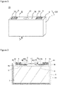
FIG. 1 is a perspective view of a secondary battery according to an embodiment. -
FIG. 2 is a cross-sectional view taken along line II-II inFIG. 1 . -
FIG. 3A is a plan view of a positive electrode original plate.FIG. 3B is a plan view of the positive electrode original plate with tabs already formed.FIG. 3C is a plan view of the positive electrode plate. -
FIG. 4A is a cross-sectional view along line aa inFIG. 3C. FIG. 4B is a cross-sectional view along line bb inFIG. 3C . -
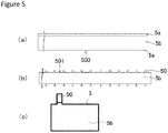
FIG. 5A is a plan view of a negative electrode original plate.FIG. 5B is a plan view of the negative electrode original plate with tabs already formed.FIG. 5C is a plan view of the negative electrode plate. -
FIG. 6 is a plan view of an electrode assembly according to the embodiment. -
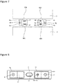
FIG. 7 is a diagram showing a state in which a positive electrode tab group is connected to a second positive electrode current collector and a negative electrode tab group is connected to a second negative electrode current collector. -
FIG. 8 is a diagram showing a surface of a sealing plate adjacent to the electrode assembly after the first positive electrode current collector and the first negative electrode current collector are attached to the sealing plate. -
FIG. 9 is a diagram showing a surface of the sealing plate adjacent to the electrode assembly after the second positive electrode current collector is attached to the first positive electrode current collector and the second negative electrode current collector is attached to the first negative electrode current collector. - The configuration of a square
secondary battery 20 as a secondary battery according to the embodiment will be described below. Note that the present invention is not limited to the following embodiments. - As shown in
FIGS. 1 and 2 , the squaresecondary battery 20 comprises abattery case 100 consisting of a bottomed hollow rectangular cylindricalexterior body 1 having an opening and asealing plate 2 for sealing the opening of the squareexterior body 1. The squareexterior body 1 and thesealing plate 2 are preferably made of metal. Anelectrode assembly 3 including a positive electrode plate and a negative electrode plate is accommodated in the squareexterior body 1 together with an electrolyte. - At the end of the
electrode assembly 3 adjacent to thesealing plate 2, a positiveelectrode tab group 40A composed of a plurality ofpositive electrode tabs 40 and a negativeelectrode tab group 50A composed of a plurality ofnegative electrode tabs 50 are provided. The positiveelectrode tab group 40A is electrically connected to apositive electrode terminal 7 via a second positive electrodecurrent collector 6b and a first positiveelectrode current collector 6a. The negativeelectrode tab group 50A is electrically connected to anegative electrode terminal 9 via a second negative electrodecurrent collector 8b and a first negative electrodecurrent collector 8a. The first positive electrodecurrent collector 6a and the second positive electrodecurrent collector 6b constitute a positiveelectrode current collector 6. Note that the positive electrodecurrent collector 6 may be used as one component. The first negative electrodecurrent collector 8a and the second negative electrodecurrent collector 8b constitute a negativeelectrode current collector 8. Note that the negative electrodecurrent collector 8 may be used as one component. - The first positive electrode
current collector 6a, the second positive electrodecurrent collector 6b, and thepositive electrode terminal 7 are preferably made of metal, and more preferably made of aluminum or an aluminum alloy. A resinexternal insulating member 10 is disposed between thepositive electrode terminal 7 and thesealing plate 2. A resininternal insulating member 11 is disposed between the first positive electrodecurrent collector 6a and the second positive electrodecurrent collector 6b, and thesealing plate 2. - The first negative electrode
current collector 8a, the second negative electrodecurrent collector 8b, and thenegative electrode terminal 9 are preferably made of metal, more preferably copper or a copper alloy. Thenegative electrode terminal 9 preferably has a portion of aluminum or an aluminum alloy and a portion of copper or a copper alloy. In this case, the portion of copper or a copper alloy is preferably connected to the first negative electrodecurrent collector 8a so that the portion of aluminum or an aluminum alloy protrudes to the outside of thesealing plate 2. A resinexternal insulating member 12 is disposed between thenegative electrode terminal 9 and thesealing plate 2. A resininternal insulating member 13 is disposed between the first negative electrodecurrent collector 8a and the second negative electrodecurrent collector 8b, and thesealing plate 2. - An
electrode assembly holder 14 composed of a resin sheet, which is made of resin, is disposed between theelectrode assembly 3 and the squareexterior body 1. Theelectrode assembly holder 14 is preferably formed by bending a resin insulating sheet into a bag shape or a box shape. Thesealing plate 2 has an electrolyticsolution injection hole 15, and the electrolyticsolution injection hole 15 is sealed by a sealingmember 16. The sealingplate 2 has agas discharge valve 17 that breaks when the pressure inside thebattery case 100 exceeds a predetermined value to discharge the gas inside thebattery case 100 to the outside of thebattery case 100. - A method of manufacturing the square
secondary battery 20 and the details of each component will now be explained. - The method of manufacturing the positive electrode plate will be first explained.
- Lithium nickel manganese cobalt oxide as a positive electrode active material, polyvinylidene fluoride (PVdF) as a binder, a carbon material as a conductive agent, and N-methyl-2-pyrrolidone (NMP) as a dispersion medium are mixed so that the lithium nickel manganese cobalt oxide: PVdF: carbon material mass ratio becomes 97.5:1:1.5, thereby preparing a positive electrode active material layer slurry.
- Alumina powder, a carbon material as a conductive material, polyvinylidene fluoride (PVdF) as a binder, and N-methyl-2-pyrrolidone (NMP) as a dispersion medium are mixed so that the alumina powder: carbon material: PVdF mass ratio becomes 83:3:14, thereby preparing a protective layer slurry.
- The positive electrode active material layer slurry and the positive electrode protective layer slurry prepared by the aforementioned method are applied to both sides of an aluminum foil as a positive electrode core body having a thickness of 15 µm with a die coater. At this time, the positive electrode active material layer slurry is applied to the center of the positive electrode core body with respect to the width direction. Further, the positive electrode protective layer slurry is applied to both ends with respect to the width direction of the region coated with the positive electrode active material layer slurry.
- The positive electrode core body coated with the positive electrode active material layer slurry and the positive electrode protective layer slurry is dried to remove NMP contained in the positive electrode active material layer slurry and the positive electrode protective layer slurry. Thus, a positive electrode active material layer and a protective layer are formed. After that, the positive electrode active material layer is compressed into a positive electrode
original plate 400 by passing it between a pair of press rollers. -
FIG. 3A is a plan view of the positive electrodeoriginal plate 400 fabricated by the aforementioned method. A positive electrodeactive material layer 4b is formed on both sides of a strip-shaped positiveelectrode core body 4a along the longitudinal direction of the positiveelectrode core body 4a. In the positiveelectrode core body 4a, a positive electrodeprotective layer 4c is formed at both ends with respect to the width direction of the region where the positive electrodeactive material layer 4b is formed. A positive electrode core body exposedportion 4d is formed at both ends of the positive electrodeoriginal plate 400 with respect to the width direction of the positive electrodeoriginal plate 400 along the longitudinal direction. Note that the thickness of the positive electrodeactive material layer 4b is preferably larger than the thickness of the positive electrodeprotective layer 4c. The thickness of the positive electrodeprotective layer 4c formed on one side of the positive electrode core body is preferably 10 to 100 µm, more preferably 15 to 50 µm. -
FIG. 3B is a plan view of the positive electrodeoriginal plate 401 with tabs already formed. Cutting the positive electrode core body exposedportion 4d of the positive electrodeoriginal plate 400 into a predetermined shape leaves the positive electrodeoriginal plate 401 with tabs already formed. When the positive electrodeoriginal plate 400 is cut to form tabs, the positive electrodeoriginal plate 400 is preferably cut by irradiating energy rays such as laser beams. - It is preferable to use a continuous oscillation (CW) laser for laser cutting. The output of the laser is preferably 500 W to 1200 W, more preferably 550 W to 1000 W, and even more preferably 600 W to 1000 W. The scanning speed of the laser is preferably 100 mm/s to 5000 mm/s. However, this is not necessarily the case. Note that a pulsed laser may be used instead.
- In the positive electrode
original plate 401 with tabs already formed, there are a plurality ofpositive electrode tabs 40 at both ends of the positive electrodeoriginal plate 401 with respect to the width direction with tabs already formed. Eachpositive electrode tab 40 is composed of a positive electrode core body exposedportion 4d. As shown inFIG. 3B , the positive electrodeoriginal plate 400 can be cut so that the positive electrodeprotective layer 4c remains at the base of eachpositive electrode tab 40 and at sides of the positive electrodeoriginal plate 401 obtained between the adjacentpositive electrode tabs 40 with tabs already formed. -
FIG. 3C is a plan view of thepositive electrode plate 4. First, the positive electrodeoriginal plate 401 with tabs already formed is cut at the central portion with respect to the width direction along the longitudinal direction of the positive electrodeoriginal plate 401 with tabs already formed. After that, the positive electrodeoriginal plate 401 with tabs already formed is cut at predetermined intervals in the longitudinal direction of the positive electrodeoriginal plate 401 with tabs already formed, thereby fabricating thepositive electrode plate 4. The positive electrodeoriginal plate 401 with tabs already formed can be cut by laser cutting, cutting using a mold or a cutter, or the like. The positive electrodeoriginal plate 401 with tabs already formed is preferably cut by a mold or a cutter. -
FIG. 4A is a cross-sectional view taken along line aa inFIG. 3C , and is a cross-sectional view of thefirst side 4A from which thepositive electrode tab 40 protrudes, in thepositive electrode plate 4.FIG. 4B is a cross-sectional view taken along line bb inFIG. 3C , and is a cross-sectional view of the end of thepositive electrode tab 40. - As shown in
FIG. 4A , thepositive electrode plate 4 has an active material layer-free portion in which the positive electrodeactive material layer 4b is not formed along thefirst side 4A in the positiveelectrode core body 4a. In the active material layer-free portion, a positive electrodeprotective layer 4c is formed adjacent to the positive electrodeactive material layer 4b. A protrusion 4x1 that protrudes from one side of the positiveelectrode core body 4a (upper side inFIG. 4A ) in the thickness direction of the positiveelectrode core body 4a is formed at the end of the active material layer-free region. Hence, the thickness of the end of the positiveelectrode core body 4a on thefirst side 4A is larger than the thickness of the portion of the positiveelectrode core body 4a where the positive electrodeactive material layer 4b is formed on the surface. Note that the thickness of the portion of the positiveelectrode core body 4a where the positive electrodeactive material layer 4b is formed on the surface is substantially equal to the thickness of the portion of the positiveelectrode core body 4a where the positive electrodeprotective layer 4c is formed on the surface. The protrusion 4x1 is a part where the positiveelectrode core body 4a is melted and solidified by laser cutting. The protrusion 4x1 is likely to occur on the side of the positiveelectrode core body 4a irradiated with the laser beam during laser cutting. - A fluorine-containing
coating 4y is formed on the end surface of the positiveelectrode core body 4a on thefirst side 4A. This makes it possible to suppress the phenomenon that the portion of the positiveelectrode core body 4a where the end surface is exposed comes into contact with the separator and damages the separator. Note that thecoating 4y is more preferably also formed on a surface of the protrusion 4x1. Even if the end surface of the positiveelectrode core body 4a comes into contact with thenegative electrode plate 5, the flow of a large current can be suppressed. Acoating 4y is preferably formed on substantially the entire end surface of the positiveelectrode core body 4a on thefirst side 4A. For example, thecoating 4y is preferably formed in a region making up 90% or more, more preferably 95% or more, still more preferably 99% or more of the total area of the end surface of the positiveelectrode core body 4a on thefirst side 4A. In thepositive electrode plate 4, thecoating 4y is not necessarily be formed on the end surface of the positiveelectrode core body 4a on the three sides other than thefirst side 4A. - The fluorine-containing
coating 4y can be a resin film. Thus, damage to the separator can be prevented more effectively. Even if the end surface of the positiveelectrode core body 4a comes into contact with thenegative electrode plate 5, the flow of a large current can be suppressed effectively. Besides, thecoating 4y is not easily peeled off from the end surface of the positiveelectrode core body 4a. - Cutting the positive electrode
original plate 400 can form a fluorine-containingcoating 4y on the end surface of thefirst side 4A of the positiveelectrode core body 4a. For example, a resin containing molten fluorine can be applied to the end surface of the positiveelectrode core body 4a. It is also conceivable to irradiate a resin containing fluorine with an energy ray such as a laser beam to melt the resin, and then spray the molten resin on the end surface of the positiveelectrode core body 4a. - The fluorine-containing
coating 4y can be defined as a coating containing aluminum fluoride. Thus, damage to the separator can be prevented more effectively. Even if the end surface of the positiveelectrode core body 4a comes into contact with thenegative electrode plate 5, the flow of a large current can be suppressed effectively. The fluorine-containingcoating 4y can be defined as a coating containing aluminum fluoride as a main component. For instance, the aluminum fluoride content in thecoating 4y can be 60 mass%. Thecoating 4y may be made of aluminum fluoride and a resin. - When the positive electrode
original plate 400 is cut, the positiveelectrode core body 4a made of molten aluminum or aluminum can be reacted with a gas containing fluorine to generate aluminum fluoride on the end surface of the positiveelectrode core body 4a. It is conceivable, for example, to laser-cut the positive electrodeoriginal plate 400 in a gas containing fluorine. Thus, a coating containing aluminum fluoride can be formed on the end surface of the positiveelectrode core body 4a. - As shown in
FIG. 4B , thecoating 4y is preferably also formed on the end surface of thepositive electrode tab 40. In thepositive electrode tab 40, thecoating 4y is preferably formed in the width direction (end surfaces defined with respect to the horizontal direction inFIG. 3C ). In thepositive electrode tab 40, thecoating 4y is preferably formed on the end surface defined with respect to the direction in which thepositive electrode tab 40 protrudes (top surface inFIG. 3C ). A protrusion 4x2 that protrudes from one side of the positiveelectrode core body 4a (upper side inFIG. 4B ) in the thickness direction of the positiveelectrode core body 4a is formed at the end of thepositive electrode tab 40. Thecoating 4y is preferably also formed on a surface of the protrusion 4x2. - The protrusion 4x1 protrudes in the direction of the thickness of the positive
electrode core body 4a, from one side of the positiveelectrode core body 4a (upper side inFIG. 4A ). Here, the height from one side of the positiveelectrode core body 4a (upper side inFIG. 4A ) to the upper end of the protrusion 4x1 is defined as the protrusion height of the protrusion 4x1. The protrusion height of the protrusion 4x1 is preferably smaller than the thickness of the positive electrodeprotective layer 4c. Such a configuration makes it possible to more effectively prevent the protrusion 4x1 from coming into contact with the separator and damaging the separator. The protrusion height of the protrusion 4x1 is preferably 2/3 or less, more preferably 1/3 or less of the thickness of the positive electrodeprotective layer 4c. Note that the protrusion height of the protrusion 4x1 can be made larger than the thickness of the positive electrodeprotective layer 4c. The positive electrodeprotective layer 4c is not an essential component. The positive electrodeprotective layer 4c is not necessarily provided on thepositive electrode plate 4. - Note that the protrusion height of the protrusion 4x1 is preferably 1/4 or less of the thickness of the portion of the positive
electrode core body 4a where the positive electrode active material layers are formed on both sides. - In the positive
electrode core body 4a, on the other side (lower side inFIG. 4A ) that is the side opposite to the side on which the protrusion 4x1 is formed, no protrusion protruding from the other side in the thickness direction of the positiveelectrode core body 4a is preferably formed. Alternatively, in the positiveelectrode core body 4a, on the other side (lower side inFIG. 4A ) that is the side opposite to the side on which the protrusion 4x1 is formed, a protrusion that protrudes from the other side in the thickness direction of the positiveelectrode core body 4a is preferably formed but its protrusion height is preferably smaller than that of the protrusion 4x1. With such a configuration, short circuits between thepositive electrode plate 4 and thenegative electrode plate 5 can be prevented more effectively. Note that the protrusion height of the protrusion formed on the other side is preferably 1/3 or less, more preferably 1/5 or less of the protrusion height of the protrusion 4x1. - A method of manufacturing a negative electrode plate will now be explained.
- Graphite as a negative electrode active material, styrene-butadiene rubber (SBR) and carboxymethyl cellulose (CMC) as a binder, and water as a dispersion medium are mixed so that the graphite: SBR: CMC mass ratio becomes 98:1:1, thereby preparing a negative electrode active material layer slurry.
- The negative electrode active material layer slurry prepared by the aforementioned method is applied to both sides of a 8-µm-thick copper foil as the negative electrode core body with a die coater.
- The negative electrode core body coated with the negative electrode active material layer slurry is dried to remove the water contained in the negative electrode active material layer slurry. Thus, the negative electrode active material layer is formed. After that, the negative electrode active material layer is compressed into the negative electrode
original plate 500 by passing it between the pair of press rollers. -
FIG. 5A is a plan view of the negative electrodeoriginal plate 500 fabricated by the aforementioned method. Negative electrodeactive material layers 5b are formed on both sides of a strip-shaped negativeelectrode core body 5a along the longitudinal direction of the negativeelectrode core body 5a. Negative electrode core body exposed portions 5c are formed at both ends of the negative electrodeoriginal plate 500 with respect to the width direction along the longitudinal direction of the negative electrodeoriginal plate 500. -
FIG. 5B is a plan view of a negative electrodeoriginal plate 501 with tabs already formed. The negative electrodeoriginal plate 501 with tabs already formed is fabricated by cutting the negative electrode core body exposed portion 5c of the negative electrodeoriginal plate 501 with tabs already formed, into a predetermined shape. The negative electrodeoriginal plate 500 can be cut by irradiation with energy rays such as lasers, a mold, a cutter, or the like. As for the negative electrodeoriginal plate 501 with tabs already formed, a plurality ofnegative electrode tabs 50 are formed, along the longitudinal direction of the negative electrodeoriginal plate 501 with tabs already formed, at both ends with respect to the width direction of the negative electrodeoriginal plate 501 with tabs already formed. Note that eachnegative electrode tabs 50 consists of a negative electrode core body exposed portion 5c. The negative electrodeoriginal plate 500 is preferably cut by irradiation with energy rays to form thenegative electrode tabs 50. -
FIG. 5C is a plan view of thenegative electrode plate 5. First, the negative electrodeoriginal plate 501 with tabs already formed is cut at the central portion with respect to the width direction along the longitudinal direction of the negative electrodeoriginal plate 501 with tabs already formed. After that, the negative electrodeoriginal plate 501 with tabs already formed is cut at predetermined intervals in the longitudinal direction of the negative electrodeoriginal plate 501 with tabs already formed, thereby fabricating thenegative electrode plate 5. - The
positive electrode plate 4 and thenegative electrode plate 5 fabricated by the aforementioned method are laminated with a separator therebetween, thereby manufacturing alaminated electrode assembly 3.FIG. 6 is a plan view of theelectrode assembly 3. A positiveelectrode tab group 40A ofpositive electrode tabs 40 and a negativeelectrode tab group 50A ofnegative electrode tabs 50 are provided at one end of theelectrode assembly 3. - Note that, when viewed in a plan view, the area of the region of the
positive electrode plate 4 in which the positive electrodeactive material layer 4b is formed is preferably smaller than the area of the region of thenegative electrode plate 5 in which the negative electrodeactive material layer 5b is formed. When theelectrode assembly 3 is viewed in a plan view, all the regions of thepositive electrode plate 4 in which the positive electrodeactive material layer 4b is formed are preferably located in the regions of thenegative electrode plate 5 where the negative electrodeactive material layer 5b is formed. - In the
electrode assembly 3, the end of the positive electrodeprotective layer 4c formed on thepositive electrode tab 40 adjacent to the distal end of thepositive electrode tab 40 is preferably located closer to the distal end of thepositive electrode tab 40 than the side of thenegative electrode plate 5 on which thenegative electrode tab 50 is formed. In other words, in thenegative electrode plate 5, in the region located on the side on which thenegative electrode tab 50 is formed and facing thepositive electrode tab 40, the positive electrodeprotective layer 4c resides between the positiveelectrode core body 4a constituting thepositive electrode tab 40 and thenegative electrode plate 5. This prevents short circuits between thepositive electrode plate 4 and thenegative electrode plate 5 more effectively. - It is preferable to use a porous film of polyolefin as the separator. It is more preferable to use a separator in which a heat-resistant layer containing ceramic is formed on the surface of the porous film of polyolefin.
- As shown in
FIG. 7 , the positiveelectrode tab groups 40A of the twoelectrode assemblies 3 are connected to the second positive electrodecurrent collector 6b, and the negativeelectrode tab groups 50A of the twoelectrode assemblies 3 are connected to the second negative electrodecurrent collector 8b. The positiveelectrode tab groups 40A are welded and joined to the second positive electrodecurrent collector 6b, thereby forming a weldedconnection portion 60. The negativeelectrode tab groups 50A are welded and joined to the second negative electrodecurrent collector 8b, thereby forming a weldedconnection portion 61. - A
thin portion 6c is formed in the second positive electrodecurrent collector 6b, and acurrent collector opening 6d is formed in thethin portion 6c. In thethin portion 6c, the second positive electrodecurrent collector 6b is connected to the first positive electrodecurrent collector 6a. In the second positive electrodecurrent collector 6b, a current collector throughhole 6e is formed in a position facing the electrolyticsolution injection hole 15 of the sealingplate 2. - A
thin portion 8c is formed in the second negative electrodecurrent collector 8b, and acurrent collector opening 8d is formed in thethin portion 8c. In thethin portion 8c, the second negative electrodecurrent collector 8b is connected to the first negative electrodecurrent collector 8a. - A connection between the positive
electrode tab group 40A and the second positive electrodecurrent collector 6b can be achieved by ultrasonic welding, resistance welding, laser welding, or the like. -
FIG. 8 is a diagram showing the inner side of the battery of the sealingplate 2 mounted with the components. Each component is mounted to the sealingplate 2 in the following manner. - An external insulating
member 10 is located on the outer side of the battery around the positive electrodeterminal insertion hole 2a of the sealingplate 2. An internal insulatingmember 11 and a first positive electrodecurrent collector 6a are located on the inner side of the battery around the positive electrodeterminal insertion hole 2a of the sealingplate 2. After that, thepositive electrode terminal 7 is inserted from the outside of the battery into the through hole of the external insulatingmember 10, the positive electrodeterminal insertion hole 2a of the sealingplate 2, the through hole of the internal insulatingmember 11, and the through hole of the first positive electrodecurrent collector 6a, and the end of thepositive electrode terminal 7 is crimped onto the first positive electrodecurrent collector 6a. Hence, thepositive electrode terminal 7 and the first positive electrodecurrent collector 6a are fixed to the sealingplate 2. Note that the crimped portion of thepositive electrode terminal 7 and the first positive electrodecurrent collector 6a are preferably connected by welding. - An external insulating
member 12 is located on the outer side of the battery around the negative electrodeterminal insertion hole 2b of the sealingplate 2. An internal insulatingmember 13 and a first negative electrodecurrent collector 8a are located on the inner side of the battery around the negative electrodeterminal insertion hole 2b of the sealingplate 2. After that, thenegative electrode terminal 9 is inserted from the outside of the battery into the through hole of the external insulatingmember 12, the negative electrodeterminal insertion hole 2b of the sealingplate 2, the through hole of the internal insulatingmember 13, and the through hole of the first negative electrodecurrent collector 8a, and the end of thenegative electrode terminal 9 is crimped onto the first negative electrodecurrent collector 8a. Hence, thenegative electrode terminal 9 and the first negative electrodecurrent collector 8a are fixed to the sealingplate 2. Note that the crimped portion of thenegative electrode terminal 9 and the first negative electrodecurrent collector 8a are preferably connected by welding. - In the internal insulating
member 11, a solution injection opening 11a is provided in a portion facing the electrolyticsolution injection hole 15 provided in the sealingplate 2. Atubular part 11b is provided at the edge of the solution injection opening 11a. -
FIG. 9 shows the inside of the battery of the sealingplate 2 after the second positive electrodecurrent collector 6b is mounted to the first positive electrodecurrent collector 6a and the second negative electrodecurrent collector 8b is mounted to the first negative electrodecurrent collector 8a. The second positive electrodecurrent collector 6b to which the positiveelectrode tab group 40A is connected is located on the internal insulatingmember 11 so that a part thereof overlaps with the first positive electrodecurrent collector 6a. Thethin portion 6c is irradiated with a laser beam, so that the second positive electrodecurrent collector 6b and the first positive electrodecurrent collector 6a are connected by welding, thereby forming a weldedconnection portion 62. The second negative electrodecurrent collector 8b to which the negativeelectrode tab group 50A is connected is located on the internal insulatingmember 13 so that a part thereof overlaps with the first negative electrodecurrent collector 8a. Thethin portion 8c is irradiated with a laser beam, so that the second negative electrodecurrent collector 8b and the first negative electrodecurrent collector 8a are connected by welding, thereby forming a weldedconnection portion 63. - Two positive
electrode tab groups 40A and two negativeelectrode tab groups 50A are curved so that the upper side of oneelectrode assembly 3 inFIG. 9 (the side further to the viewer inFIG. 9 ) and the upper side of the other electrode assembly 3 (the side closer to the viewer inFIG. 9 ) cone into contact with each other directly or via another member. As a result, the twoelectrode assemblies 3 are combined into one unit. The twoelectrode assemblies 3 are located in anelectrode assembly holder 14 consisting of a box-shaped or a bag-shaped insulating sheet. - One positive
electrode tab group 40A and the other positiveelectrode tab group 40A are curved in different directions. One negativeelectrode tab group 50A and the other negativeelectrode tab group 50A are curved in different directions. - The two
electrode assemblies 3 wrapped in theelectrode assembly holder 14 are inserted into the squareexterior body 1. The sealingplate 2 and the squareexterior body 1 are then welded to seal the opening of the squareexterior body 1 with the sealingplate 2. The electrolytic solution is then injected into the squareexterior body 1 through the electrolyticsolution injection hole 15 provided in the sealingplate 2. After that, the electrolyticsolution injection hole 15 is sealed with a sealing member such as a blind rivet. Thus, the squaresecondary battery 20 is completed. - The thickness of the fluorine-containing coating can be in the range of 0.05 to 5 µm. Note that the thickness of the fluorine-containing coating is preferably less than 1 µm or in the range of 0.1 to 0.8 µm. When the thickness of the fluorine-containing coating is made relatively small, the phenomenon that a coating containing fluorine is peeled off from the end surface of the core body can be suppressed.
- When the fluorine-containing coating contains aluminum fluoride as a main component, the thickness of the coating is preferably less than 1 µm, more preferably in the range of 0.05 to 0.8 µm, still more preferably in the range of 0.1 to 0.6 µm. When the thickness of the coating is made relatively small, even if the end surface of the core body comes into contact with an electrode plate of a different polarity, the end surface of the core body is not completely insulated and current can flow between the end surface of the core body and the electrode plate of a different polarity. This avoids the situation where the insulation between the positive electrode plate and the negative electrode plate is maintained only by the coating, which may allow energy to be released when the end surface of the core body comes into contact with an electrode plate of a different polarity.
- The protective layer provided on the electrode plate is preferably a layer having lower electrical conductivity than the core body constituting the electrode plate. The protective layer is preferably a layer having lower electrical conductivity than the active material layer. Although the aforementioned embodiment showed the example in which the protective layer is provided on the positive electrode plate, the protective layer may be provided on the negative electrode plate instead.
- The protective layer preferably contains a ceramic and a binder. The ceramic may be an oxide, nitride, boride, carbide, silicide, sulfide or the like. The ceramic may be aluminum oxide, boehmite, titanium oxide, silicon oxide, tungsten oxide, or the like. However, this is not necessarily the case. The binder is preferably a resin-based binder. However, this is not necessarily the case. Note that the protective layer does not necessarily contain a ceramic. For example, the protective layer may be a resin layer. The protective layer may be made of a conductive material of a carbon material or the like. Note that the protective layer does not necessarily contain a conductive material.
- The positive electrode core body is preferably made of aluminum or an aluminum alloy containing aluminum as a main component. Note that the aluminum alloy is preferably an aluminum alloy with an aluminum content of 90 mass% or more, more preferably an aluminum alloy with an aluminum content of 95 mass% or more.
- The negative electrode core body is preferably made of copper or a copper alloy containing copper as a main component. Note that the copper alloy is preferably a copper alloy with a copper content of 95 mass% or more, more preferably a copper alloy with a copper content of 99 mass% or more.
- The thickness of the core body is preferably 5 to 30 µm, more preferably 5 to 20 µm.
- The aforementioned embodiment showed the example in which the positive electrode
protective layer 4c is provided on thepositive electrode plate 4. However, the protective layer is not an essential component and is not necessarily provided. - The protective layer and the coating provided on the electrode plate have different structures.
- Although the aforementioned embodiment showed the example in which two electrode assemblies are located in the battery case, one or three or more electrode assemblies may be used. The electrode assemblies may be laminated electrode assemblies or wound electrode assemblies.
- The details of the configuration of the end portion of the active material layer-free portion have been described for the positive electrode plate in the aforementioned embodiment, and the same configuration can be applied to the negative electrode plate.
- Although the example in which the positive electrode current collector and the negative electrode current collector are each composed of two parts has been described in the aforementioned embodiment, the positive electrode current collector and the negative electrode current collector may each be composed of one part.
- Known materials can be used for the positive electrode plate, the negative electrode plate, the separator, the electrolyte, and the like.
-
- 20 square secondary battery
- 1 square exterior body
- 2 sealing plate
- 2a positive electrode terminal insertion hole
- 2b negative electrode terminal insertion hole
- 100 battery case
- 3 electrode assembly
- 4 positive electrode plate
- 4A first side
- 4a positive electrode core body
- 4b positive electrode active material layer
- 4c positive electrode protective layer
- 4d positive electrode core body exposed portion
- 4x1, 4x2 protrusion
- 4y coating
- 40 positive electrode tab
- 40A positive electrode tab group
- 400 positive electrode original plate
- 401 positive electrode original plate with tabs already formed
- 5 negative electrode plate
- 5a negative electrode core body
- 5b negative electrode active material layer
- 50 negative electrode tab
- 50A negative electrode tab group
- 6 positive electrode current collector
- 6a first positive electrode current collector
- 6b second positive electrode current collector
- 6c thin portion
- 6d current collector opening
- 6e current collector through hole
- 7 positive electrode terminal
- 8 negative electrode current collector
- 8a first negative electrode current collector
- 8b second negative electrode current collector
- 8c thin portion
- 8d current collector opening
- 9 negative electrode terminal
- 10 external insulating member
- 11 internal insulating member
- 11a solution injection opening
- 11b tubular part
- 12 external insulating member
- 13 internal insulating member
- 14 electrode assembly holder
- 15 electrolytic solution injection hole
- 16 sealed member
- 17 gas discharge valve
- 60, 61, 62, 63 welded connection portion
Claims (8)
- A secondary battery electrode plate having a metal core body and an active material layer on both sides of the core body, whereinthe electrode plate has a first side and a tab that protrudes from the first side, anda coating containing fluorine is formed on an end surface of the core body on the first side.
- The secondary battery electrode plate according to Claim 1, wherein the thickness of the core body on the first side is larger than that of a portion of the core body, the portion having the active material layer formed on the portion.
- The secondary battery electrode plate according to Claim 1 or 2, wherein the core body is made of aluminum or an aluminum alloy.
- The secondary battery electrode plate according to any one of Claims 1 to 3, wherein the coating is a resin coating containing fluorine.
- The secondary battery electrode plate according to any one of Claims 1 to 3, wherein the coating is a coating containing aluminum fluoride.
- The secondary battery electrode plate according to any one of Claims 1 to 5, wherein the coating is also formed on an end surface of the tab.
- The secondary battery electrode plate according to any one of Claims 1 to 6, wherein the thickness of the coating is less than 1 µm.
- A secondary battery comprising:the electrode plate according to any one of Claims 1 to 7; andanother electrode plate having a polarity different from that of the electrode plate.
Applications Claiming Priority (2)
| Application Number | Priority Date | Filing Date | Title |
|---|---|---|---|
| JP2018236843 | 2018-12-19 | ||
| PCT/JP2019/049491 WO2020130000A1 (en) | 2018-12-19 | 2019-12-17 | Secondary battery electrode plate and secondary battery using same |
Publications (3)
| Publication Number | Publication Date |
|---|---|
| EP3902030A1 true EP3902030A1 (en) | 2021-10-27 |
| EP3902030A4 EP3902030A4 (en) | 2022-02-09 |
| EP3902030B1 EP3902030B1 (en) | 2025-09-03 |
Family
ID=71101828
Family Applications (1)
| Application Number | Title | Priority Date | Filing Date |
|---|---|---|---|
| EP19899059.0A Active EP3902030B1 (en) | 2018-12-19 | 2019-12-17 | Secondary battery electrode plate and secondary battery using same |
Country Status (5)
| Country | Link |
|---|---|
| US (1) | US12224443B2 (en) |
| EP (1) | EP3902030B1 (en) |
| JP (1) | JP7398392B2 (en) |
| CN (1) | CN112868114A (en) |
| WO (1) | WO2020130000A1 (en) |
Family Cites Families (13)
| Publication number | Priority date | Publication date | Assignee | Title |
|---|---|---|---|---|
| JP3263466B2 (en) | 1993-02-05 | 2002-03-04 | 三洋電機株式会社 | Non-aqueous electrolyte secondary battery |
| JPH117962A (en) | 1997-04-24 | 1999-01-12 | Japan Storage Battery Co Ltd | Non-aqueous electrolyte secondary battery |
| JP2008010854A (en) | 2006-06-01 | 2008-01-17 | Matsushita Electric Ind Co Ltd | Electric double layer capacitor and manufacturing method thereof |
| US20120189889A1 (en) * | 2011-01-24 | 2012-07-26 | Dukjung Kim | Secondary battery |
| WO2012128160A1 (en) * | 2011-03-23 | 2012-09-27 | 三洋電機株式会社 | Positive electrode plate for anhydrous electrolyte secondary cell, method for manufacturing positive electrode plate, and anhydrous electrolyte secondary cell and method for manufacturing same |
| JP2012199162A (en) * | 2011-03-23 | 2012-10-18 | Sanyo Electric Co Ltd | Laminate covered secondary battery |
| JP5360247B2 (en) * | 2012-02-22 | 2013-12-04 | 株式会社豊田自動織機 | Positive electrode, power storage device, vehicle |
| JP2015099658A (en) * | 2013-11-18 | 2015-05-28 | トヨタ自動車株式会社 | Non-aqueous electrolyte secondary battery |
| JP6633283B2 (en) * | 2014-07-31 | 2020-01-22 | 株式会社東芝 | Nonaqueous electrolyte battery, method for manufacturing nonaqueous electrolyte battery, and battery pack |
| JP6520097B2 (en) | 2014-12-11 | 2019-05-29 | 株式会社Gsユアサ | Storage element |
| JPWO2017057762A1 (en) | 2015-09-30 | 2018-07-19 | 積水化学工業株式会社 | Electrode part of lithium ion secondary battery, lithium ion secondary battery, and method for producing lithium ion secondary battery |
| US10461327B2 (en) * | 2016-03-29 | 2019-10-29 | Samsung Sdi Co., Ltd. | Positive electrode for non-aqueous electrolyte secondary battery and non-aqueous electrolyte secondary battery |
| KR20180001229A (en) | 2016-06-27 | 2018-01-04 | 삼성에스디아이 주식회사 | Method for manufacturing secondary battery and secondary battery using the same |
-
2019
- 2019-12-17 JP JP2020561471A patent/JP7398392B2/en active Active
- 2019-12-17 CN CN201980068345.1A patent/CN112868114A/en active Pending
- 2019-12-17 US US17/311,967 patent/US12224443B2/en active Active
- 2019-12-17 WO PCT/JP2019/049491 patent/WO2020130000A1/en not_active Ceased
- 2019-12-17 EP EP19899059.0A patent/EP3902030B1/en active Active
Also Published As
| Publication number | Publication date |
|---|---|
| EP3902030A4 (en) | 2022-02-09 |
| WO2020130000A1 (en) | 2020-06-25 |
| EP3902030B1 (en) | 2025-09-03 |
| US12224443B2 (en) | 2025-02-11 |
| US20220029167A1 (en) | 2022-01-27 |
| JPWO2020130000A1 (en) | 2021-11-04 |
| CN112868114A (en) | 2021-05-28 |
| JP7398392B2 (en) | 2023-12-14 |
Similar Documents
| Publication | Publication Date | Title |
|---|---|---|
| EP3902047B1 (en) | Rectangular secondary battery | |
| US12176580B2 (en) | Secondary battery and method for manufacturing same | |
| CN109671969B (en) | Method for manufacturing secondary battery | |
| US12548860B2 (en) | Electrode plate for secondary cell, and secondary cell using same | |
| US12237497B2 (en) | Electrode plate for secondary batteries, and secondary battery using same | |
| US11978895B2 (en) | Secondary battery electrode plate comprising a protrusion and secondary battery using the same | |
| CN113439350B (en) | Electrode plate and method for manufacturing the same, secondary battery and method for manufacturing the same | |
| JP7353302B2 (en) | secondary battery | |
| EP3902030B1 (en) | Secondary battery electrode plate and secondary battery using same | |
| US20230207863A1 (en) | Battery | |
| EP3905384A1 (en) | Electrode plate and secondary battery using same |
Legal Events
| Date | Code | Title | Description |
|---|---|---|---|
| STAA | Information on the status of an ep patent application or granted ep patent |
Free format text: STATUS: THE INTERNATIONAL PUBLICATION HAS BEEN MADE |
|
| PUAI | Public reference made under article 153(3) epc to a published international application that has entered the european phase |
Free format text: ORIGINAL CODE: 0009012 |
|
| STAA | Information on the status of an ep patent application or granted ep patent |
Free format text: STATUS: REQUEST FOR EXAMINATION WAS MADE |
|
| 17P | Request for examination filed |
Effective date: 20210622 |
|
| AK | Designated contracting states |
Kind code of ref document: A1 Designated state(s): AL AT BE BG CH CY CZ DE DK EE ES FI FR GB GR HR HU IE IS IT LI LT LU LV MC MK MT NL NO PL PT RO RS SE SI SK SM TR |
|
| A4 | Supplementary search report drawn up and despatched |
Effective date: 20220111 |
|
| RIC1 | Information provided on ipc code assigned before grant |
Ipc: H01M 50/572 20210101ALI20220104BHEP Ipc: H01M 50/534 20210101ALI20220104BHEP Ipc: H01M 4/66 20060101ALI20220104BHEP Ipc: H01M 4/13 20100101AFI20220104BHEP |
|
| DAV | Request for validation of the european patent (deleted) | ||
| DAX | Request for extension of the european patent (deleted) | ||
| RIC1 | Information provided on ipc code assigned before grant |
Ipc: H01M 50/593 20210101ALN20250211BHEP Ipc: H01M 50/588 20210101ALN20250211BHEP Ipc: H01M 50/572 20210101ALI20250211BHEP Ipc: H01M 50/534 20210101ALI20250211BHEP Ipc: H01M 4/66 20060101ALI20250211BHEP Ipc: H01M 4/13 20100101AFI20250211BHEP |
|
| GRAP | Despatch of communication of intention to grant a patent |
Free format text: ORIGINAL CODE: EPIDOSNIGR1 |
|
| STAA | Information on the status of an ep patent application or granted ep patent |
Free format text: STATUS: GRANT OF PATENT IS INTENDED |
|
| INTG | Intention to grant announced |
Effective date: 20250325 |
|
| GRAS | Grant fee paid |
Free format text: ORIGINAL CODE: EPIDOSNIGR3 |
|
| GRAA | (expected) grant |
Free format text: ORIGINAL CODE: 0009210 |
|
| STAA | Information on the status of an ep patent application or granted ep patent |
Free format text: STATUS: THE PATENT HAS BEEN GRANTED |
|
| AK | Designated contracting states |
Kind code of ref document: B1 Designated state(s): AL AT BE BG CH CY CZ DE DK EE ES FI FR GB GR HR HU IE IS IT LI LT LU LV MC MK MT NL NO PL PT RO RS SE SI SK SM TR |
|
| REG | Reference to a national code |
Ref country code: CH Ref legal event code: EP |
|
| REG | Reference to a national code |
Ref country code: DE Ref legal event code: R096 Ref document number: 602019075327 Country of ref document: DE |
|
| REG | Reference to a national code |
Ref country code: IE Ref legal event code: FG4D |
|
| REG | Reference to a national code |
Ref country code: NL Ref legal event code: MP Effective date: 20250903 |
|
| PGFP | Annual fee paid to national office [announced via postgrant information from national office to epo] |
Ref country code: GB Payment date: 20251229 Year of fee payment: 7 |
|
| PG25 | Lapsed in a contracting state [announced via postgrant information from national office to epo] |
Ref country code: NO Free format text: LAPSE BECAUSE OF FAILURE TO SUBMIT A TRANSLATION OF THE DESCRIPTION OR TO PAY THE FEE WITHIN THE PRESCRIBED TIME-LIMIT Effective date: 20251203 |
|
| REG | Reference to a national code |
Ref country code: LT Ref legal event code: MG9D |
|
| PG25 | Lapsed in a contracting state [announced via postgrant information from national office to epo] |
Ref country code: FI Free format text: LAPSE BECAUSE OF FAILURE TO SUBMIT A TRANSLATION OF THE DESCRIPTION OR TO PAY THE FEE WITHIN THE PRESCRIBED TIME-LIMIT Effective date: 20250903 |
|
| PG25 | Lapsed in a contracting state [announced via postgrant information from national office to epo] |
Ref country code: HR Free format text: LAPSE BECAUSE OF FAILURE TO SUBMIT A TRANSLATION OF THE DESCRIPTION OR TO PAY THE FEE WITHIN THE PRESCRIBED TIME-LIMIT Effective date: 20250903 |
|
| PGFP | Annual fee paid to national office [announced via postgrant information from national office to epo] |
Ref country code: FR Payment date: 20251222 Year of fee payment: 7 |
|
| PG25 | Lapsed in a contracting state [announced via postgrant information from national office to epo] |
Ref country code: GR Free format text: LAPSE BECAUSE OF FAILURE TO SUBMIT A TRANSLATION OF THE DESCRIPTION OR TO PAY THE FEE WITHIN THE PRESCRIBED TIME-LIMIT Effective date: 20251204 |
|
| PG25 | Lapsed in a contracting state [announced via postgrant information from national office to epo] |
Ref country code: SE Free format text: LAPSE BECAUSE OF FAILURE TO SUBMIT A TRANSLATION OF THE DESCRIPTION OR TO PAY THE FEE WITHIN THE PRESCRIBED TIME-LIMIT Effective date: 20250903 |
|
| PG25 | Lapsed in a contracting state [announced via postgrant information from national office to epo] |
Ref country code: LV Free format text: LAPSE BECAUSE OF FAILURE TO SUBMIT A TRANSLATION OF THE DESCRIPTION OR TO PAY THE FEE WITHIN THE PRESCRIBED TIME-LIMIT Effective date: 20250903 |
|
| PG25 | Lapsed in a contracting state [announced via postgrant information from national office to epo] |
Ref country code: BG Free format text: LAPSE BECAUSE OF FAILURE TO SUBMIT A TRANSLATION OF THE DESCRIPTION OR TO PAY THE FEE WITHIN THE PRESCRIBED TIME-LIMIT Effective date: 20250903 Ref country code: PL Free format text: LAPSE BECAUSE OF FAILURE TO SUBMIT A TRANSLATION OF THE DESCRIPTION OR TO PAY THE FEE WITHIN THE PRESCRIBED TIME-LIMIT Effective date: 20250903 |
|
| PG25 | Lapsed in a contracting state [announced via postgrant information from national office to epo] |
Ref country code: RS Free format text: LAPSE BECAUSE OF FAILURE TO SUBMIT A TRANSLATION OF THE DESCRIPTION OR TO PAY THE FEE WITHIN THE PRESCRIBED TIME-LIMIT Effective date: 20251203 |
|
| PG25 | Lapsed in a contracting state [announced via postgrant information from national office to epo] |
Ref country code: ES Free format text: LAPSE BECAUSE OF FAILURE TO SUBMIT A TRANSLATION OF THE DESCRIPTION OR TO PAY THE FEE WITHIN THE PRESCRIBED TIME-LIMIT Effective date: 20250903 |
|
| REG | Reference to a national code |
Ref country code: AT Ref legal event code: MK05 Ref document number: 1834246 Country of ref document: AT Kind code of ref document: T Effective date: 20250903 |
|
| PG25 | Lapsed in a contracting state [announced via postgrant information from national office to epo] |
Ref country code: NL Free format text: LAPSE BECAUSE OF FAILURE TO SUBMIT A TRANSLATION OF THE DESCRIPTION OR TO PAY THE FEE WITHIN THE PRESCRIBED TIME-LIMIT Effective date: 20250903 |
|
| PG25 | Lapsed in a contracting state [announced via postgrant information from national office to epo] |
Ref country code: SM Free format text: LAPSE BECAUSE OF FAILURE TO SUBMIT A TRANSLATION OF THE DESCRIPTION OR TO PAY THE FEE WITHIN THE PRESCRIBED TIME-LIMIT Effective date: 20250903 |
|
| PGFP | Annual fee paid to national office [announced via postgrant information from national office to epo] |
Ref country code: DE Payment date: 20251222 Year of fee payment: 7 |
|
| PG25 | Lapsed in a contracting state [announced via postgrant information from national office to epo] |
Ref country code: AT Free format text: LAPSE BECAUSE OF FAILURE TO SUBMIT A TRANSLATION OF THE DESCRIPTION OR TO PAY THE FEE WITHIN THE PRESCRIBED TIME-LIMIT Effective date: 20250903 |
|
| PG25 | Lapsed in a contracting state [announced via postgrant information from national office to epo] |
Ref country code: RO Free format text: LAPSE BECAUSE OF FAILURE TO SUBMIT A TRANSLATION OF THE DESCRIPTION OR TO PAY THE FEE WITHIN THE PRESCRIBED TIME-LIMIT Effective date: 20250903 Ref country code: IT Free format text: LAPSE BECAUSE OF FAILURE TO SUBMIT A TRANSLATION OF THE DESCRIPTION OR TO PAY THE FEE WITHIN THE PRESCRIBED TIME-LIMIT Effective date: 20250903 |
|
| PG25 | Lapsed in a contracting state [announced via postgrant information from national office to epo] |
Ref country code: IS Free format text: LAPSE BECAUSE OF FAILURE TO SUBMIT A TRANSLATION OF THE DESCRIPTION OR TO PAY THE FEE WITHIN THE PRESCRIBED TIME-LIMIT Effective date: 20260103 |
|
| PG25 | Lapsed in a contracting state [announced via postgrant information from national office to epo] |
Ref country code: CZ Free format text: LAPSE BECAUSE OF FAILURE TO SUBMIT A TRANSLATION OF THE DESCRIPTION OR TO PAY THE FEE WITHIN THE PRESCRIBED TIME-LIMIT Effective date: 20250903 Ref country code: PT Free format text: LAPSE BECAUSE OF FAILURE TO SUBMIT A TRANSLATION OF THE DESCRIPTION OR TO PAY THE FEE WITHIN THE PRESCRIBED TIME-LIMIT Effective date: 20260105 |
|
| PG25 | Lapsed in a contracting state [announced via postgrant information from national office to epo] |
Ref country code: SK Free format text: LAPSE BECAUSE OF FAILURE TO SUBMIT A TRANSLATION OF THE DESCRIPTION OR TO PAY THE FEE WITHIN THE PRESCRIBED TIME-LIMIT Effective date: 20250903 Ref country code: EE Free format text: LAPSE BECAUSE OF FAILURE TO SUBMIT A TRANSLATION OF THE DESCRIPTION OR TO PAY THE FEE WITHIN THE PRESCRIBED TIME-LIMIT Effective date: 20250903 |
|
| REG | Reference to a national code |
Ref country code: DE Ref legal event code: R097 Ref document number: 602019075327 Country of ref document: DE |
|
| PG25 | Lapsed in a contracting state [announced via postgrant information from national office to epo] |
Ref country code: LT Free format text: LAPSE BECAUSE OF FAILURE TO SUBMIT A TRANSLATION OF THE DESCRIPTION OR TO PAY THE FEE WITHIN THE PRESCRIBED TIME-LIMIT Effective date: 20250903 |
|
| PG25 | Lapsed in a contracting state [announced via postgrant information from national office to epo] |
Ref country code: MC Free format text: LAPSE BECAUSE OF FAILURE TO SUBMIT A TRANSLATION OF THE DESCRIPTION OR TO PAY THE FEE WITHIN THE PRESCRIBED TIME-LIMIT Effective date: 20250903 |
|
| PG25 | Lapsed in a contracting state [announced via postgrant information from national office to epo] |
Ref country code: DK Free format text: LAPSE BECAUSE OF FAILURE TO SUBMIT A TRANSLATION OF THE DESCRIPTION OR TO PAY THE FEE WITHIN THE PRESCRIBED TIME-LIMIT Effective date: 20250903 |
|
| PLBE | No opposition filed within time limit |
Free format text: ORIGINAL CODE: 0009261 |
|
| STAA | Information on the status of an ep patent application or granted ep patent |
Free format text: STATUS: NO OPPOSITION FILED WITHIN TIME LIMIT |
|
| REG | Reference to a national code |
Ref country code: CH Ref legal event code: L10 Free format text: ST27 STATUS EVENT CODE: U-0-0-L10-L00 (AS PROVIDED BY THE NATIONAL OFFICE) Effective date: 20260715 |
|
| REG | Reference to a national code |
Ref country code: CH Ref legal event code: H13 Free format text: ST27 STATUS EVENT CODE: U-0-0-H10-H13 (AS PROVIDED BY THE NATIONAL OFFICE) Effective date: 20260723 |
|
| 26N | No opposition filed |
Effective date: 20260604 |