EP3901983A1 - Charged particle beam system - Google Patents
Charged particle beam system Download PDFInfo
- Publication number
- EP3901983A1 EP3901983A1 EP21166267.1A EP21166267A EP3901983A1 EP 3901983 A1 EP3901983 A1 EP 3901983A1 EP 21166267 A EP21166267 A EP 21166267A EP 3901983 A1 EP3901983 A1 EP 3901983A1
- Authority
- EP
- European Patent Office
- Prior art keywords
- cartridge
- sample
- magazine
- cartridges
- charged particle
- Prior art date
- Legal status (The legal status is an assumption and is not a legal conclusion. Google has not performed a legal analysis and makes no representation as to the accuracy of the status listed.)
- Granted
Links
Images



Classifications
-
- H—ELECTRICITY
- H01—ELECTRIC ELEMENTS
- H01J—ELECTRIC DISCHARGE TUBES OR DISCHARGE LAMPS
- H01J37/00—Discharge tubes with provision for introducing objects or material to be exposed to the discharge, e.g. for the purpose of examination or processing thereof
- H01J37/02—Details
- H01J37/18—Vacuum locks ; Means for obtaining or maintaining the desired pressure within the vessel
- H01J37/185—Means for transferring objects between different enclosures of different pressure or atmosphere
-
- H—ELECTRICITY
- H01—ELECTRIC ELEMENTS
- H01J—ELECTRIC DISCHARGE TUBES OR DISCHARGE LAMPS
- H01J37/00—Discharge tubes with provision for introducing objects or material to be exposed to the discharge, e.g. for the purpose of examination or processing thereof
- H01J37/26—Electron or ion microscopes; Electron or ion diffraction tubes
- H01J37/261—Details
- H01J37/265—Controlling the tube; circuit arrangements adapted to a particular application not otherwise provided, e.g. bright-field-dark-field illumination
-
- H—ELECTRICITY
- H01—ELECTRIC ELEMENTS
- H01J—ELECTRIC DISCHARGE TUBES OR DISCHARGE LAMPS
- H01J37/00—Discharge tubes with provision for introducing objects or material to be exposed to the discharge, e.g. for the purpose of examination or processing thereof
- H01J37/02—Details
- H01J37/20—Means for supporting or positioning the object or the material; Means for adjusting diaphragms or lenses associated with the support
-
- H—ELECTRICITY
- H01—ELECTRIC ELEMENTS
- H01J—ELECTRIC DISCHARGE TUBES OR DISCHARGE LAMPS
- H01J37/00—Discharge tubes with provision for introducing objects or material to be exposed to the discharge, e.g. for the purpose of examination or processing thereof
- H01J37/26—Electron or ion microscopes; Electron or ion diffraction tubes
-
- H—ELECTRICITY
- H01—ELECTRIC ELEMENTS
- H01J—ELECTRIC DISCHARGE TUBES OR DISCHARGE LAMPS
- H01J2237/00—Discharge tubes exposing object to beam, e.g. for analysis treatment, etching, imaging
- H01J2237/002—Cooling arrangements
-
- H—ELECTRICITY
- H01—ELECTRIC ELEMENTS
- H01J—ELECTRIC DISCHARGE TUBES OR DISCHARGE LAMPS
- H01J2237/00—Discharge tubes exposing object to beam, e.g. for analysis treatment, etching, imaging
- H01J2237/18—Vacuum control means
- H01J2237/184—Vacuum locks
-
- H—ELECTRICITY
- H01—ELECTRIC ELEMENTS
- H01J—ELECTRIC DISCHARGE TUBES OR DISCHARGE LAMPS
- H01J2237/00—Discharge tubes exposing object to beam, e.g. for analysis treatment, etching, imaging
- H01J2237/20—Positioning, supporting, modifying or maintaining the physical state of objects being observed or treated
- H01J2237/2001—Maintaining constant desired temperature
-
- H—ELECTRICITY
- H01—ELECTRIC ELEMENTS
- H01J—ELECTRIC DISCHARGE TUBES OR DISCHARGE LAMPS
- H01J2237/00—Discharge tubes exposing object to beam, e.g. for analysis treatment, etching, imaging
- H01J2237/20—Positioning, supporting, modifying or maintaining the physical state of objects being observed or treated
- H01J2237/2002—Controlling environment of sample
- H01J2237/2003—Environmental cells
- H01J2237/2004—Biological samples
-
- H—ELECTRICITY
- H01—ELECTRIC ELEMENTS
- H01J—ELECTRIC DISCHARGE TUBES OR DISCHARGE LAMPS
- H01J2237/00—Discharge tubes exposing object to beam, e.g. for analysis treatment, etching, imaging
- H01J2237/20—Positioning, supporting, modifying or maintaining the physical state of objects being observed or treated
- H01J2237/204—Means for introducing and/or outputting objects
-
- H—ELECTRICITY
- H01—ELECTRIC ELEMENTS
- H01J—ELECTRIC DISCHARGE TUBES OR DISCHARGE LAMPS
- H01J2237/00—Discharge tubes exposing object to beam, e.g. for analysis treatment, etching, imaging
- H01J2237/26—Electron or ion microscopes
- H01J2237/28—Scanning microscopes
- H01J2237/2802—Transmission microscopes
Definitions
- the present invention relates to a charged particle beam system.
- a sample When a sample is observed with a charged particle beam system such as an electron microscope, if the sample is a biological sample or polymeric material, and if the sample is irradiated with a charged particle beam, the morphology of the sample may be destroyed. As a result, the sample under normal condition may not be observed. In this case, if the sample is cooled, for example, below liquid nitrogen temperature, the morphology of the sample is not easily destroyed when it is irradiated with an electron beam. Consequently, the sample in its normal state can be observed.
- a charged particle beam system such as an electron microscope
- patent document 1 discloses a charged particle beam system having a sample container for accommodating a sample and a refrigerant for cooling the sample.
- the sample container can be placed in communication with a sample exchange chamber via a partition valve.
- the interior of the sample container can be evacuated while the partition valve is closed. Therefore, the partition valve can be opened after the interior of the sample container is evacuated to a vacuum state and the refrigerant is solidified. Consequently, even if the refrigerant remains in the sample container, a sample can be introduced into the sample exchange chamber from the sample container, and the cooled sample can be readily loaded into the sample chamber.
- Patent document 1 JP-A-2015-88237
- the sample is held in a cartridge which comes in various types.
- the cartridge will collide against the objective lens or other member, in which case the operational range of the sample stage (e.g., its tilt angle) must be restricted.
- an identifier is engraved in a side surface of each cartridge or a small part of a color is buried therein. The identifier or the color of the buried part is detected with a sensor to identify the type of the cartridge.
- the cartridge when the cartridge is cooled, the cartridge is frosted even in a vacuum state. This makes it impossible to precisely read the identifier or the color of the buried part. Hence, the cartridge type may be misdetected.
- One aspect of the charged particle beam system associated with the present invention comprises:
- the first cartridge has a first measurement surface that is at a first range or distance to the laser range finder when the first cartridge is placed in the measurement position (i.e., the first cartridge is the selected cartridge).
- the second cartridge has a second measurement surface that is at a second range, different from the first range, to the laser range finder when the second cartridge is placed in the measurement position (i.e., the second cartridge is the selected cartridge).
- the cartridge type can be precisely identified without being affected by the build-up of frost on the cartridge.
- an electron microscope that irradiates a sample with an electron beam to permit observation or analysis of the sample is set forth as one example of the charged particle beam system associated with the present invention.
- the charged particle beam system associated with the present invention may also be an instrument which irradiates a sample with a charged particle beam other than an electron beam (e.g., an ion beam) to allow observations and analysis of the sample.
- FIG. 1 schematically shows main portions of the electron microscope, 100, associated with the present embodiment.
- X-, Y-, and Z-axes are shown as mutually perpendicular axes.
- the electron microscope 100 includes a plurality of cartridges 2, a cartridge magazine 4, a sample container 10, a sample chamber 20, a cartridge holder 24, a sample stage or sample stage assembly 26, a stage control section 28, a sample exchange chamber 30, partition valves 32, 40, vacuum pumping equipment 50, a storage cabinet 60, a cooling block 70, a first transport arm device 80, a second transport arm device 82, a photosensor 90, a laser range finder 92, and a controller 101.
- the electron microscope 100 is a transmission electron microscope (TEM).
- the sample container 10 is used to carry a cooled sample.
- a sample and a refrigerant for cooling it are accommodated in the sample container 10.
- the refrigerant is liquid nitrogen.
- Other examples include liquid methane, liquid ethane, and liquid butane. No restriction is imposed on the refrigerant as long as it can cool the sample and it condenses if vacuum pumped by the vacuum pumping equipment 50 described later.
- the sample container 10 accommodates the cartridge magazine 4 in which the plural cartridges 2 are loaded.
- the cooled sample is held in each cartridge 2, which is a member in the form of a flat plate.
- Each cartridge 2 in which the sample is held is inserted and loaded into the magazine 4.
- the magazine 4 has a plurality of cartridge holding portions and thus can accommodate the plural cartridges 2.
- the magazine 4 has four cartridge holding portions. When the cartridges 2 are loaded into the magazine 4, the cartridges 2 are inserted into the cartridge holding portions.
- the sample is a biological sample, a polymeric material, or the like whose morphology is easily destroyed by a charged particle beam such as an electron beam or an ion beam.
- the sample is cooled, for example, below liquid nitrogen temperature (e.g., a cryogenic temperature) and then held in each cartridge 2.
- cartridges 2 Two types, for example, of cartridges 2 are for use with the electron microscope 100.
- a first cartridge 2a of a first type shown in FIG. 2 and a second cartridge 2b of a second type shown in FIG. 3 are used.
- FIG. 2 schematically shows the first cartridge 2a that has a rotational drive mechanism 202 for rotating the sample, for example, within a horizontal plane.
- the first cartridge 2a is provided with a through hole 201 for passage of an electron beam.
- the sample is held over the through hole 201.
- the sample is held to the first cartridge 2a, for example, with a C-ring.
- the first cartridge 2a has a side surface 204 provided with a first recess 206.
- the surface of the first cartridge 2a that defines the first recess 206 constitutes a first measurement surface 208, which in turn is a flat surface, for example.
- FIG. 3 schematically shows the second cartridge 2b which has a tilt mechanism 212 for tilting the sample, for example.
- the second cartridge 2b is provided with a through hole 211 for passage of an electron beam.
- the sample is held over the through hole 211.
- the sample is held to the second cartridge 2b, for example, with a C-ring.
- the second cartridge 2b has a side surface 214 provided with a second recess 216.
- the surface of the second cartridge 2b that defines the second recess 216 constitutes a second measurement surface 218, which in turn is a flat surface, for example.
- laser light emitted from the laser range finder 92 falls on the second measurement surface 218.
- the laser range finder 92 measures the distance between the laser range finder 92 and the second measurement surface 218.
- a second distance is defined between the second measurement surface 218 and the laser range finder 92.
- the first recess 206 has a depth D1 greater than the depth D2 of the second recess 216. Accordingly, the first distance between the laser range finder 92 and the first cartridge 2a is greater than the second distance between the laser range finder 92 and the second cartridge 2b by the difference between the depths D1 and D2.
- the cartridges 2 and magazine 4 are preferably made from a thermally conductive material.
- the sample chamber 20 is a space inside a microscope column 22.
- This interior space is vacuum pumped (i.e., gas inside the chamber is evacuated in order to obtain a desired vacuum state) by vacuum pumping equipment (not shown). Consequently, the sample chamber 20 is maintained in vacuum.
- An ion pump, a scroll pump, a turbomolecular pump, and so on can be used as the vacuum pumping equipment for vacuum pumping the sample chamber 20.
- the cartridge holder 24 is disposed in the sample chamber 20 and supports the cartridges 2 in the chamber 20.
- the sample is placed in position, for example, by moving or tilting the cartridge holder 24 with the sample stage 26, which is a goniometer stage, for example.
- the stage control section 28 controls the sample stage 26.
- the sample chamber 20 is a space in which the sample is irradiated with an electron beam.
- the electron microscope 100 has an electron source (one example of charged particle source), an illumination optical system, an imaging optical system, and a detector, none of which are shown.
- the electron beam released from the electron source is condensed by the illumination optical system and made to impinge on the sample held to the cartridges 2 in the sample chamber 20.
- the electron beam transmitted through the sample is brought to a focus by the imaging optical system and detected by the detector. As a result, an electron microscope image can be obtained.
- the sample exchange chamber 30 is in communication with the sample chamber 20 via the intervening partition valve 32.
- the partition valve 32 is used as a vacuum partition between the sample exchange chamber 30 and the sample chamber 20.
- the sample exchange chamber 30 and the sample chamber 20 are placed in communication with each other by opening the partition valve 32.
- the sample exchange chamber 30 and the sample chamber 20 are isolated from each other by closing the partition valve 32.
- the sample exchange chamber 30 is a space surrounded by a vacuum vessel 34 and vacuum pumped by the vacuum pumping equipment 50. Consequently, the sample exchange chamber 30 can be kept in vacuum.
- the sample container 10 is connected into the sample exchange chamber 30.
- the sample container 10 is connected into the sample exchange chamber 30 via a connective member 42, which in turn is connected into the sample exchange chamber 30.
- the connective member 42 has an end surface on which an O-ring 44 is mounted to provide a hermetic seal between the sample container 10 and the connective member 42.
- the partition valve 40 When the sample container 10 is connected into the sample exchange chamber 30, the partition valve 40 is placed between the sample exchange chamber 30 and the sample container 10.
- the partition valve 40 is used as a vacuum partition between the sample exchange chamber 30 and the sample container 10.
- the sample exchange chamber 30 and the sample container 10 are placed in communication with each other by opening the partition valve 40.
- the sample exchange chamber 30 and the sample container 10 are placed out of communication with each other by closing the partition valve 40.
- the vacuum pumping equipment 50 operates to vacuum pump the sample container 10. This pumping operation of the equipment 50 can be done when the sample container 10 is connected into the sample exchange chamber 30 and, at the same time, the partition valve 40 is closed. Consequently, the interior of the sample container 10 is vacuum pumped and the freezing point of the refrigerant rises. Hence, the refrigerant can be solidified.
- the vacuum pumping equipment 50 vacuum pumps the sample container 10 via an exhaust pipe 52 which is connected with the connective member 42 in the illustrated example.
- a solenoid valve 54 is mounted in the exhaust pipe 52.
- the vacuum pumping equipment 50 vacuum pumps the sample exchange chamber 30 via an exhaust pipe 56 in which a solenoid valve 58 is mounted.
- An oil-sealed rotary vacuum pump, an ion pump, a scroll pump, a turbomolecular pump, or the like can be used as the vacuum pumping equipment 50.
- the storage cabinet 60 is mounted in the sample exchange chamber 30 and can hold the cartridges 2 therein.
- the storage cabinet 60 has a plurality of storage portions 62 that hold the plural cartridges 2, respectively.
- the plural cartridges 2 can be held in the storage cabinet 60.
- the storage portions 62 are arranged along the Z-axis.
- the storage cabinet 60 is cooled and so it can store samples while cooling them.
- the storage cabinet 60 can be moved in an up/down direction, i.e., along the Z-axis.
- Each cartridge 2 can be conveyed between the magazine 4 and the storage cabinet 60 using the first transport arm device 80 and the second transport arm device 82. Also, each cartridge 2 can be transported between the cartridge holder 24 and the storage cabinet 60 using the second transport arm device 82.
- the cooling block 70 is mounted in the sample exchange chamber 30.
- the cooling block 70 is cooled.
- the cooling block 70 is in thermal communication with a tank, for example, storing the refrigerant such as liquid nitrogen in a manner not illustrated.
- the first transport arm device 80 has a grip mechanism 802. When the grip mechanism 802 is in a standby position, the cooling block 70 is so located that the grip mechanism 802 strikes the cooling block 70.
- the first transport arm device 80 carries the magazine 4 between the sample container 10 and the sample exchange chamber 30.
- the first transport arm device 80 moves the magazine 4 located in the sample container 10 into the sample exchange chamber 30.
- the first transport arm device 80 moves the magazine 4 from inside the sample exchange chamber 30 into the sample container 10.
- FIG. 4 schematically shows only a front end portion of the first transport arm device 80.
- the first transport arm device 80 has the grip mechanism 802, a resilient member 804, a rod 806, and a drive mechanism 808.
- the grip mechanism 802 grips the magazine 4.
- the grip mechanism 802 has two arms which hold the magazine 4 therebetween to grip the magazine 4.
- the grip mechanism 802 is connected to the resilient member 804.
- the grip mechanism 802 is connected to the resilient member 804 via a connective member 803.
- the connective member 803 is received in the rod 806 and connected to the resilient member 804.
- the connective member 803 is greater in width than an opening formed in the rod 806. Therefore, the connective member 803 does not protrude out of the rod 806.
- the resilient member 804 is received in the rod 806.
- the resilient member 804 is a compression spring.
- the grip mechanism 802 is coupled to the front end of the resilient member 804 via the connective member 803.
- the grip mechanism 802 is mounted to the front end of the rod 806 via the resilient member 804.
- the rod 806 is hollow and receives the resilient member 804 therein.
- the drive mechanism 808 can move the grip mechanism 802 in an up/down direction, i.e., along the Z-axis. Consequently, in the first transport arm device 80, the magazine 4 can be moved up and down.
- the rod 806 is capable of expansion and contraction, and the drive mechanism 808 moves the grip mechanism 802 by elongating and contracting the rod 806.
- the drive mechanism 808 may move the grip mechanism 802 by inserting or withdrawing the rod 806.
- the second transport arm device 82 carries each cartridge 2 between the sample exchange chamber 30 and the sample chamber 20. For example, the second transport arm device 82 takes out the cartridges 2 from the magazine 4 held by the first transport arm device 80 and loads them into the cartridge holder 24 within the sample chamber 20. Also, the second transport arm device 82 takes out the cartridges 2 from the cartridge holder 24 and inserts them into the magazine 4 held by the first transport arm device 80.
- the second transport arm device 82 carries the cartridges 2 between the magazine 4 held by the first transport arm device 80 and the storage cabinet 60.
- the second transport arm device 82 has a grip mechanism 820 for gripping a selected one of the cartridges 2, a rod 822, and a drive mechanism 824 for moving the grip mechanism 820.
- the grip mechanism 820 has two arms to grip each cartridge 2, for example, by holding it between the arms.
- the drive mechanism 824 can move the grip mechanism 820 in a horizontal direction, i.e., along the X-axis. Consequently, the second transport arm device 82 can move each cartridge 2 in a horizontal direction.
- the photosensor 90 has a light emitting section and a light receiving section which are disposed on the opposite sides of that of the cartridges 2 in the magazine 4 which is located in the detection position.
- the photosensor 90 detects the presence or absence of that cartridge 2 (hereinafter may be referred to as the (currently) "measured cartridge” in the magazine 4).
- the light emitting section emits light, and light is received by the light receiving section and the amount of light is detected.
- the presence or absence of the measured cartridge 2 in the magazine 4 is detected based on the amount of light detected by the photosensor 90.
- the laser range finder 92 measures the range or distance to the measured cartridge 2 received in the magazine 4. In particular, the laser range finder 92 measures the range to the measurement surface of the measured cartridge 2 located in the measurement position. More specifically, the laser range finder 92 measures the distance between the point hit by laser light and the laser range finder 92. The laser range finder 92 determines the range, for example, based on the phase difference between the emitted light and the reflected light.
- the laser range finder 92 is disposed outside the sample exchange chamber 30.
- the laser range finder 92 emits the laser light to the measured cartridge 2 in the sample exchange chamber 30 through a window formed in the vacuum vessel 34.
- the finder 92 detects light reflected from the cartridge 2 also through the window formed in the vacuum vessel 34.
- the type of the measured cartridge 2 is identified based on the range measured by the laser range finder 92.
- the controller 101 controls various portions of the electron microscope 100.
- FIG. 5 illustrates the configuration of the controller 101.
- the controller 101 includes a manual control section 110, a display section 112, a storage section 114, and a processing section 120.
- the manual control section 110 permits a user to enter manual control information, and outputs the entered manual control information to the processing section 120.
- the function of the manual control section 110 can be realized by a hardware device such as a keyboard, a mouse, buttons, a touch panel, or a touch pad.
- the display section 112 displays images generated by the processing section 120.
- the function of the display section 112 can be realized by an LCD (liquid crystal display) or a touch panel that functions also as the manual control section 110.
- the storage section 114 also serves as a working area for the processing section 120.
- the function of the storage section 114 can be realized by a hard disk, a RAM (Random Access Memory), or the like.
- the functions of the processing section 120 can be realized by executing computer programs using a hardware device such as various processors (e.g., CPUs (central processing units)) or DSP (digital signal processor)).
- the processing section 120 includes a control unit 122 and a discriminator 124.
- the control unit 122 controls the partition valves 32, 40, solenoid valves 54, 58, the storage cabinet 60, the first transport arm device 80, the second transport arm device 82, and others.
- the discriminator 124 detects the presence or absence of the measured cartridge 2 in the magazine 4 based on the amount of light detected by the photosensor 90. If there is the measured cartridge 2, the light from the photosensor 90 is blocked by the cartridge 2. If there is no such cartridge 2, the light from the photosensor 90 is detected without being blocked by any cartridge 2. Therefore, if the amount of light detected by the photosensor 90 is below a preset threshold value, the discriminator 124 determines that there is the cartridge 2 to be measured. If the amount of light detected by the photosensor 90 is in excess of the preset threshold value, the discriminator determines that there is no such cartridge 2.
- the discriminator 124 detects the type of the measured cartridge 2 based on the range measured by the laser range finder 92. As shown in FIGS. 2 and 3 , the depth D1 of the first recess 206 is greater than the depth D2 of the second recess 216. Therefore, the range to the first cartridge 2a measured by the laser range finder 92 and the range to the second cartridge 2b measured by the laser range finder 92 are different by an amount equal to the difference between the depths D1 and D2. Utilizing this, the discriminator 124 detects the type of the measured cartridge 2.
- the discriminator 124 determines the type of the measured cartridge 2 corresponding to the measured range by searching through a table showing the relationship between the types of the plural cartridges 2 and their ranges measured by the laser range finder 92, the table being stored in the storage section 114.
- the discriminator 124 may identify the type of the measured cartridge 2 by comparing the range measured by the laser range finder 92 with the threshold value.
- the threshold value is set to a value in between the first distance from the laser range finder 92 to the first measurement surface 208 of the first cartridge 2a and the second distance from the laser range finder 92 to the second measurement surface 218 of the second cartridge 2b. In this case, if the range measured by the laser range finder 92 and the threshold value are compared, and if the range is greater than the threshold value, it can be determined that the measured cartridge is the first cartridge 2a. If the range is smaller than the threshold value, it can be determined that the measured cartridge is the second cartridge 2b.
- FIG. 6 is a schematic cross-sectional view of the sample container 10. As shown in FIG. 6 , each cartridge 2 in which a sample is held is inserted and thus received into the magazine 4. In the illustrated example, plural cartridges 2 are received in the magazine 4. The sample is embedded in ice.
- the sample container 10 has a receiving portion 12 and a cover 14.
- FIG. 7 schematically shows a state in which the sample container 10 is mounted in the sample exchange chamber 30. Then, as shown in FIG. 7 , the sample container 10 is mounted in the sample exchange chamber 30. In particular, the cover 14 of the sample container 10 is removed and mounted to the connective member 42. Consequently, the sample container 10 is placed in communication with the sample exchange chamber 30 via the partition valve 40. At this time, the partition valve 40 is closed. The O-ring 44 seals between the connective member 42 and the sample container 10.
- the interior of the sample exchange chamber 30 is vacuum pumped and maintained in vacuum by the vacuum puming equipment 50. That is, the solenoid valve 58 is kept open. The partition valve 32 is closed.
- FIG. 8 is a flowchart illustrating one example of the operational sequence of the electron microscope 100.
- FIGS. 9-17 illustrate the operational sequence of the electron microscope 100.
- control unit 122 If a user enters an instruction through the manual control section 110, for example, to introduce the magazine 4 into the sample exchange chamber 30, the control unit 122 starts a processing sequence.
- the control unit 122 first opens the solenoid valve 54 (S100). As a result, the interior of the sample container 10 is vacuum pumped. This causes the refrigerant in the sample container 10 to solidify. The control unit 122 closes the solenoid valve 54 after a lapse of a given time, for example.
- the control unit 122 After closing the solenoid valve 54, the control unit 122 opens the partition valve 40 as shown in FIG. 9 (S102). Because the refrigerant in the sample container 10 is solidified at this time, the degree of vacuum in the sample exchange chamber 30 can be prevented from deteriorating even if the refrigerant is left in the sample container 10.
- the control unit 122 causes the grip mechanism 802 to grip the magazine 4 (S104).
- the grip mechanism 802 moves from inside the sample exchange chamber 30 into the sample container 10 and strikes the top of the magazine 4.
- the resilient member 804 contracts to thereby absorb the shock produced by the collision of the grip mechanism 802 against the sample container 10; otherwise, a vacuum leak would occur.
- the control unit 122 causes the grip mechanism 802 to grip the magazine 4.
- control unit 122 causes the drive mechanism 808 to move the grip mechanism 802 into the standby position within the sample exchange chamber 30 as shown in FIG. 11 (S106). Consequently, the magazine 4 is conveyed into the sample exchange chamber 30.
- the grip mechanism 802 When moved into the standby position, the grip mechanism 802 strikes the cooling block 70. As shown in FIG. 12 , this enables the resilient member 804 to be extended. In consequence, positional deviation of the magazine 4 can be prevented.
- the resilient member 804 contracts and may not return to its original state completely. This causes a positional deviation of the magazine 4.
- the second transport arm device 82 may not take out an intended one of the cartridges 2 from the magazine 4.
- the photosensor 90 may not detect the amount of light correctly.
- the laser range finder 92 may not precisely measure the range to the intended cartridge 2.
- the resilient member 804 is made extensible by causing the grip mechanism 802 to collide with the cooling block 70. Consequently, positional deviation of the magazine 4 can be prevented and thus the foregoing problems can be avoided.
- control unit 122 closes the partition valve 40 (S108).
- the control unit 122 controls and operates the second transport arm device 82 such that the plural cartridges 2 received in the magazine 4 are aligned in orientation (S110).
- control unit 122 causes the first transport arm device 80 to move the magazine 4 such that the cartridge 2 received in the first stage of the magazine 4 is placed in the delivery position. Then, the control unit 122 causes the second transport arm device 82 to grip the front end of the cartridge 2 located in the delivery position and to adjust the orientation of this cartridge 2. Similar processing is performed for the cartridges 2 in the second and following stages. Consequently, all the cartridges 2 received in the magazine 4 can be aligned in orientation.
- the discriminator 124 detects the presence or absence of any cartridge 2 (S112). As shown in FIG. 14 , the control unit 122 causes the first transport arm device 80 to move the magazine 4 such that the first stage of the magazine 4 is placed into the detection position. The discriminator 124 derives the amount of light from the first stage of the magazine 4 detected by the photosensor 90 and determines the presence or absence of any cartridge 2 in the first stage based on the amount of light. Similar processing is performed for the cartridges 2 in the second and following stages. As a result, information about the presence or absence of the cartridges 2 in the magazine 4 can be obtained, and this information is stored in the storage section 114.
- the discriminator 124 detects the type of each cartridge 2 (S114). As shown in FIG. 15 , the control unit 122 causes the first transport arm device 80 to move the magazine 4 such that the first stage of the magazine 4 is placed into the measurement position. The discriminator 124 determines the type of the cartridge 2 in the first stage of the magazine 4 based on the range to the cartridge 2 in the first stage measured by the laser range finder 92. Similar processing is done for the cartridges 2 in the second and following stages. For any stage for which it is determined that there is no cartridge 2, processing to identify the cartridge 2 is not performed. Because of the processing described so far, the types of all the cartridges 2 received in the magazine 4 can be identified. Information about the types of the cartridges 2 is stored in the storage section 114.
- control unit 122 opens the partition valve 32 (S116).
- the control unit 122 then causes the second transport arm device 82 to load a specified one of the cartridges 2 into the cartridge holder 24 in the sample chamber 20 (S 118).
- the user specifies, through the manual control section 110, the position of the cartridge 2 in the magazine 4 at which the sample to be observed is held. For example, if the second stage in the magazine 4 is specified as the position of the cartridge 2 to be detected or discerned, the control unit 122 causes the first transport arm device 80 to move the magazine 4 such that the cartridge 2 received in the second stage of the magazine 4 is placed into the delivery position. Then, the control unit 122 causes the second transport arm device 82 to grip the cartridge 2 located in the delivery position. The control unit 122 then causes the second transport arm device 82 to carry this cartridge 2 into the sample chamber 20 and to load the cartridge 2 in the cartridge holder 24. Consequently, the cartridge 2 in which the sample to be observed is held can be loaded in the cartridge holder 24.
- the control unit 122 moves the grip mechanism 820 into the sample exchange chamber 30 and closes the partition valve 32 as shown in FIG. 17 (S120).
- the control unit 122 sends information about the type of the cartridge 2 to the stage control section 28 that controls the sample stage 26 (S 122).
- the stage control section 28 limits the range of operation of the cartridge 2 based on the information about the type of the cartridge 2 (S 124). For example, the stage control section 28 limits the angular range through which the cartridge 2 can be tilted based on the information about the type of the cartridge 2. Because of the processing described so far, the cartridge 2 is introduced into the sample chamber 20.
- the cartridges 2 received in the magazine 4 are introduced into the sample chamber 20.
- the cartridges 2 received in the magazine 4 may be stored in the storage cabinet 60 after the types of the cartridges 2 are detected.
- the first cartridge 2a out of the plural cartridges 2 has the first measurement surface 208 that is at the first distance from the laser range finder 92 when placed in the measurement position.
- the second cartridge 2b out of the plural cartridges 2 has the second measurement surface 218 that is at the second distance from the laser range finder 92 when placed in the measurement position.
- the discriminator 124 determines the type of each cartridge 2 based on its range measured by the laser range finder 92. Therefore, in the electron microscope 100, the type of the cartridge 2 can be determined precisely.
- the type of a cartridge is identified by reading, with the sensor, either an identifier engraved in a side surface of the cartridge or the color of a small part buried in the side surface, for example, frost forming on the cartridge may hinder the reading of the identifier or color, and the type of the cartridge may be misdetected.
- the type of each cartridge 2 is identified based on the range measured by the laser range finder 92 and so the identification is not affected by frost forming on the cartridge 2. Consequently, the type of the cartridge 2 can be determined precisely.
- the first recess 206 is formed in the side surface 204 of the first cartridge 2a, and the first measurement surface 208 defines the surface of the first cartridge 2a provided with the first recess 206.
- the second recess 216 is formed in the side surface 214 of the second cartridge 2b, and the second measurement surface 218 is the surface of the second cartridge 2b that defines the second recess 216.
- the depth D1 of the first recess 206 is greater than the depth D2 of the second recess 216. Therefore, in the electron microscope 100, it is possible to discriminate between the first cartridge 2a and the second cartridge 2b based on their ranges measured by the laser range finder 92.
- the electron microscope 100 includes: the second transport arm device 82 for conveying a selected one of the cartridges 2 between the sample exchange chamber 30 and the sample chamber 20; and the control unit 122 for controlling the second transport arm device 82.
- the control unit 122 makes the cartridges 2 received in the magazine 4 align in orientation via the second transport arm device 82. Therefore, in the electron microscope 100, the ranges to the cartridges 2 can be precisely measured by the laser range finder 92. Consequently, the electron microscope 100 can precisely determine the type of each cartridge 2.
- the first transport arm device 80 has the grip mechanism 802 for gripping the magazine 4, the resilient member 804 coupled to the grip mechanism 802, the rod 806 receiving the resilient member 804, and the drive mechanism 808 for moving the grip mechanism 802.
- the grip mechanism 802 is coupled to the resilient member 804 and, therefore, when the grip mechanism 802 strikes on the magazine 4, the resultant shock can be absorbed.
- the electron microscope 100 includes the cooling block 70 which collides on the grip mechanism 802 when it is placed in the standby position. Therefore, the resilient member 804 can be elongated by causing the grip mechanism 802 to collide on the cooling block 70. Consequently, positional deviation of the magazine 4 can be prevented.
- first cartridge 2a there are two types of cartridges 2, i.e., first cartridge 2a and second cartridge 2b.
- the cartridges 2 of two or more types can be distinguished from each other by making different the depths of the recesses respectively formed in the side surfaces of the cartridges 2.
- FIG. 18 shows another example of the second cartridge 2b.
- this cartridge 2b has a flat side surface 214 provided with no recess.
- the second measurement surface 218 may be the side surface 214 of the second cartridge 2b. Even in this case, the first cartridge 2a and the second cartridge 2b can be discriminated from each other based on the result of the measurement made by the laser range finder 92.
- the charged particle beam system associated with the present invention is a transmission electron microscope. No restriction is placed on the charged particle beam system associated with the present invention as long as the system uses a charged particle beam such as a beam of electrons or ions.
- the charged particle beam system associated with the present invention may be an electron microscope (such as a scanning transmission electron microscope (STEM) or a scanning electron microscope (SEM)), an electron probe microanalyzer (EPMA), a focused ion beam (FIB) system, an electron beam exposure system, or the like
- the present invention is not restricted to the foregoing embodiments but rather can be implemented in various modified forms.
- the present invention embraces configurations (e.g., configurations identical in function and method) which are substantially identical to the configurations described in the above embodiments.
- the invention embraces configurations which are similar to the configurations described in the above embodiments except that their nonessential portions have been replaced.
- the invention embraces configurations which are similar to the configurations described in the above embodiments except that a well-known technique is added.
Landscapes
- Chemical & Material Sciences (AREA)
- Analytical Chemistry (AREA)
- Sampling And Sample Adjustment (AREA)
Abstract
Description
- The present invention relates to a charged particle beam system.
- When a sample is observed with a charged particle beam system such as an electron microscope, if the sample is a biological sample or polymeric material, and if the sample is irradiated with a charged particle beam, the morphology of the sample may be destroyed. As a result, the sample under normal condition may not be observed. In this case, if the sample is cooled, for example, below liquid nitrogen temperature, the morphology of the sample is not easily destroyed when it is irradiated with an electron beam. Consequently, the sample in its normal state can be observed.
- However, in order to introduce a sample in a cooled state into the interior of an electron microscope that is in a vacuum state, adhesion of crystalline ice or frost to the sample should be prevented. For this purpose, various contrivances have been made.
- For example, patent document 1 discloses a charged particle beam system having a sample container for accommodating a sample and a refrigerant for cooling the sample. The sample container can be placed in communication with a sample exchange chamber via a partition valve. In this charged particle beam system, the interior of the sample container can be evacuated while the partition valve is closed. Therefore, the partition valve can be opened after the interior of the sample container is evacuated to a vacuum state and the refrigerant is solidified. Consequently, even if the refrigerant remains in the sample container, a sample can be introduced into the sample exchange chamber from the sample container, and the cooled sample can be readily loaded into the sample chamber.
- In this charged particle beam system, the sample is held in a cartridge which comes in various types. Depending on the cartridge type, the cartridge will collide against the objective lens or other member, in which case the operational range of the sample stage (e.g., its tilt angle) must be restricted. Accordingly, in the charged particle beam system, an identifier is engraved in a side surface of each cartridge or a small part of a color is buried therein. The identifier or the color of the buried part is detected with a sensor to identify the type of the cartridge.
- However, when the cartridge is cooled, the cartridge is frosted even in a vacuum state. This makes it impossible to precisely read the identifier or the color of the buried part. Hence, the cartridge type may be misdetected.
- One aspect of the charged particle beam system associated with the present invention comprises:
- a plurality of cartridges including a first cartridge of a first type and a second cartridge of a second type different from the first type;
- a cartridge magazine capable of accommodating the cartridges;
- a sample chamber that is vacuum pumped;
- a sample exchange chamber in communication with the sample chamber via a partition valve;
- a first transport arm device for conveying the magazine in the sample exchange chamber;
- a laser range finder for measuring a range to a selected one of the cartridges accommodated in the magazine, the selected cartridge being placed in a measurement position; and
- a discriminator for determining the type of the selected cartridge based on the range measured by the laser range finder.
- The first cartridge has a first measurement surface that is at a first range or distance to the laser range finder when the first cartridge is placed in the measurement position (i.e., the first cartridge is the selected cartridge). The second cartridge has a second measurement surface that is at a second range, different from the first range, to the laser range finder when the second cartridge is placed in the measurement position (i.e., the second cartridge is the selected cartridge).
- With this charged particle beam system, the cartridge type can be precisely identified without being affected by the build-up of frost on the cartridge.
-
-
FIG. 1 is a block diagram of an electron microscope associated with one embodiment of the present invention. -
FIG. 2 is a schematic representation of a first cartridge. -
FIG. 3 is a schematic representation of a second cartridge. -
FIG. 4 is a schematic cross-sectional view of a first transport arm device. -
FIG. 5 is a block diagram illustrating the configuration of a controller. -
FIG. 6 is a schematic cross-sectional view of a sample container. -
FIG. 7 is a block diagram, partially in cross section, illustrating a state in which the sample container is loaded in a sample exchange chamber. -
FIG. 8 is a flowchart illustrating one example of the operational sequence of the electron microscope ofFIG. 1 . -
FIG. 9 is a block diagram, partially in cross section, of the electron microscope ofFIG. 1 , illustrating its operation. -
FIG. 10 shows fragmentary cross-sectional views of the first transport arm device. -
FIG. 11 is a block diagram illustrating the operation of the electron microscope ofFIG. 1 . -
FIG. 12 shows fragmentary cross-sectional views of the first transport arm device. -
FIG. 13 shows fragmentary cross-sectional views of the first cartridge, illustrating its different operational states. -
FIGS. 14 ,15 ,16 , and17 are block diagrams, partially in cross section, of the electron microscope ofFIG. 1 , illustrating its different operational states. -
FIG. 18 is a schematic representation of another example of the second cartridge. - Preferred embodiments of the present invention are hereinafter described in detail with reference to the accompanying drawings. It is to be noted that embodiments given below are not intended to unduly restrict the content of the present invention set forth in the claims and that not all the configurations set forth below are essential constituent components of the present invention.
- In the following description, an electron microscope that irradiates a sample with an electron beam to permit observation or analysis of the sample is set forth as one example of the charged particle beam system associated with the present invention. The charged particle beam system associated with the present invention may also be an instrument which irradiates a sample with a charged particle beam other than an electron beam (e.g., an ion beam) to allow observations and analysis of the sample.
- An electron microscope associated with one embodiment of the present invention is first described by referring to
FIG. 1 , which schematically shows main portions of the electron microscope, 100, associated with the present embodiment. InFIG. 1 , X-, Y-, and Z-axes are shown as mutually perpendicular axes. - As shown in
FIG. 1 , theelectron microscope 100 includes a plurality ofcartridges 2, acartridge magazine 4, asample container 10, asample chamber 20, acartridge holder 24, a sample stage orsample stage assembly 26, astage control section 28, asample exchange chamber 30,partition valves vacuum pumping equipment 50, astorage cabinet 60, acooling block 70, a firsttransport arm device 80, a secondtransport arm device 82, aphotosensor 90, a laser range finder 92, and acontroller 101. In the following description, theelectron microscope 100 is a transmission electron microscope (TEM). - The
sample container 10 is used to carry a cooled sample. A sample and a refrigerant for cooling it are accommodated in thesample container 10. One example of the refrigerant is liquid nitrogen. Other examples include liquid methane, liquid ethane, and liquid butane. No restriction is imposed on the refrigerant as long as it can cool the sample and it condenses if vacuum pumped by thevacuum pumping equipment 50 described later. - The
sample container 10 accommodates thecartridge magazine 4 in which theplural cartridges 2 are loaded. The cooled sample is held in eachcartridge 2, which is a member in the form of a flat plate. Eachcartridge 2 in which the sample is held is inserted and loaded into themagazine 4. - The
magazine 4 has a plurality of cartridge holding portions and thus can accommodate theplural cartridges 2. In the illustrated example, themagazine 4 has four cartridge holding portions. When thecartridges 2 are loaded into themagazine 4, thecartridges 2 are inserted into the cartridge holding portions. - The sample is a biological sample, a polymeric material, or the like whose morphology is easily destroyed by a charged particle beam such as an electron beam or an ion beam. The sample is cooled, for example, below liquid nitrogen temperature (e.g., a cryogenic temperature) and then held in each
cartridge 2. - Two types, for example, of
cartridges 2 are for use with theelectron microscope 100. In particular, afirst cartridge 2a of a first type shown inFIG. 2 and asecond cartridge 2b of a second type shown inFIG. 3 are used. -
FIG. 2 schematically shows thefirst cartridge 2a that has arotational drive mechanism 202 for rotating the sample, for example, within a horizontal plane. Thefirst cartridge 2a is provided with a throughhole 201 for passage of an electron beam. The sample is held over the throughhole 201. The sample is held to thefirst cartridge 2a, for example, with a C-ring. - The
first cartridge 2a has aside surface 204 provided with afirst recess 206. The surface of thefirst cartridge 2a that defines thefirst recess 206 constitutes afirst measurement surface 208, which in turn is a flat surface, for example. When thefirst cartridge 2a is placed in a measurement position, laser light emitted from thelaser range finder 92 hits thefirst measurement surface 208, and thelaser range finder 92 measures the distance between thefinder 92 and thefirst measurement surface 208. When thefirst cartridge 2a is in the measurement position, a first distance is defined between thefirst measurement surface 208 and thelaser range finder 92. -
FIG. 3 schematically shows thesecond cartridge 2b which has atilt mechanism 212 for tilting the sample, for example. Thesecond cartridge 2b is provided with a throughhole 211 for passage of an electron beam. The sample is held over the throughhole 211. The sample is held to thesecond cartridge 2b, for example, with a C-ring. - The
second cartridge 2b has aside surface 214 provided with asecond recess 216. The surface of thesecond cartridge 2b that defines thesecond recess 216 constitutes asecond measurement surface 218, which in turn is a flat surface, for example. When thesecond cartridge 2b is placed in the measurement position, laser light emitted from thelaser range finder 92 falls on thesecond measurement surface 218. When thesecond cartridge 2b is placed in the measurement position, thelaser range finder 92 measures the distance between thelaser range finder 92 and thesecond measurement surface 218. When thesecond cartridge 2b is in the measurement position, a second distance is defined between thesecond measurement surface 218 and thelaser range finder 92. - The
first recess 206 has a depth D1 greater than the depth D2 of thesecond recess 216. Accordingly, the first distance between thelaser range finder 92 and thefirst cartridge 2a is greater than the second distance between thelaser range finder 92 and thesecond cartridge 2b by the difference between the depths D1 and D2. Thecartridges 2 andmagazine 4 are preferably made from a thermally conductive material. - As shown in
FIG. 1 , thesample chamber 20 is a space inside amicroscope column 22. This interior space is vacuum pumped (i.e., gas inside the chamber is evacuated in order to obtain a desired vacuum state) by vacuum pumping equipment (not shown). Consequently, thesample chamber 20 is maintained in vacuum. An ion pump, a scroll pump, a turbomolecular pump, and so on can be used as the vacuum pumping equipment for vacuum pumping thesample chamber 20. - The
cartridge holder 24 is disposed in thesample chamber 20 and supports thecartridges 2 in thechamber 20. In thesample chamber 20, the sample is placed in position, for example, by moving or tilting thecartridge holder 24 with thesample stage 26, which is a goniometer stage, for example. Thestage control section 28 controls thesample stage 26. - The
sample chamber 20 is a space in which the sample is irradiated with an electron beam. Theelectron microscope 100 has an electron source (one example of charged particle source), an illumination optical system, an imaging optical system, and a detector, none of which are shown. In theelectron microscope 100, the electron beam released from the electron source is condensed by the illumination optical system and made to impinge on the sample held to thecartridges 2 in thesample chamber 20. The electron beam transmitted through the sample is brought to a focus by the imaging optical system and detected by the detector. As a result, an electron microscope image can be obtained. - The
sample exchange chamber 30 is in communication with thesample chamber 20 via the interveningpartition valve 32. Thepartition valve 32 is used as a vacuum partition between thesample exchange chamber 30 and thesample chamber 20. Thesample exchange chamber 30 and thesample chamber 20 are placed in communication with each other by opening thepartition valve 32. Thesample exchange chamber 30 and thesample chamber 20 are isolated from each other by closing thepartition valve 32. - The
sample exchange chamber 30 is a space surrounded by avacuum vessel 34 and vacuum pumped by thevacuum pumping equipment 50. Consequently, thesample exchange chamber 30 can be kept in vacuum. - The
sample container 10 is connected into thesample exchange chamber 30. In the illustrated example, thesample container 10 is connected into thesample exchange chamber 30 via aconnective member 42, which in turn is connected into thesample exchange chamber 30. Theconnective member 42 has an end surface on which an O-ring 44 is mounted to provide a hermetic seal between thesample container 10 and theconnective member 42. - When the
sample container 10 is connected into thesample exchange chamber 30, thepartition valve 40 is placed between thesample exchange chamber 30 and thesample container 10. Thepartition valve 40 is used as a vacuum partition between thesample exchange chamber 30 and thesample container 10. Thesample exchange chamber 30 and thesample container 10 are placed in communication with each other by opening thepartition valve 40. Thesample exchange chamber 30 and thesample container 10 are placed out of communication with each other by closing thepartition valve 40. - The
vacuum pumping equipment 50 operates to vacuum pump thesample container 10. This pumping operation of theequipment 50 can be done when thesample container 10 is connected into thesample exchange chamber 30 and, at the same time, thepartition valve 40 is closed. Consequently, the interior of thesample container 10 is vacuum pumped and the freezing point of the refrigerant rises. Hence, the refrigerant can be solidified. - The
vacuum pumping equipment 50 vacuum pumps thesample container 10 via anexhaust pipe 52 which is connected with theconnective member 42 in the illustrated example. Asolenoid valve 54 is mounted in theexhaust pipe 52. Furthermore, thevacuum pumping equipment 50 vacuum pumps thesample exchange chamber 30 via anexhaust pipe 56 in which asolenoid valve 58 is mounted. An oil-sealed rotary vacuum pump, an ion pump, a scroll pump, a turbomolecular pump, or the like can be used as thevacuum pumping equipment 50. - The
storage cabinet 60 is mounted in thesample exchange chamber 30 and can hold thecartridges 2 therein. Thestorage cabinet 60 has a plurality ofstorage portions 62 that hold theplural cartridges 2, respectively. Thus, theplural cartridges 2 can be held in thestorage cabinet 60. In the illustrated example, thestorage portions 62 are arranged along the Z-axis. - The
storage cabinet 60 is cooled and so it can store samples while cooling them. Thestorage cabinet 60 can be moved in an up/down direction, i.e., along the Z-axis. - Each
cartridge 2 can be conveyed between themagazine 4 and thestorage cabinet 60 using the firsttransport arm device 80 and the secondtransport arm device 82. Also, eachcartridge 2 can be transported between thecartridge holder 24 and thestorage cabinet 60 using the secondtransport arm device 82. - The
cooling block 70 is mounted in thesample exchange chamber 30. Thecooling block 70 is cooled. Thecooling block 70 is in thermal communication with a tank, for example, storing the refrigerant such as liquid nitrogen in a manner not illustrated. The firsttransport arm device 80 has agrip mechanism 802. When thegrip mechanism 802 is in a standby position, thecooling block 70 is so located that thegrip mechanism 802 strikes thecooling block 70. - The first
transport arm device 80 carries themagazine 4 between thesample container 10 and thesample exchange chamber 30. The firsttransport arm device 80 moves themagazine 4 located in thesample container 10 into thesample exchange chamber 30. Furthermore, the firsttransport arm device 80 moves themagazine 4 from inside thesample exchange chamber 30 into thesample container 10. -
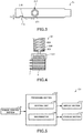
FIG. 4 schematically shows only a front end portion of the firsttransport arm device 80. The firsttransport arm device 80 has thegrip mechanism 802, aresilient member 804, arod 806, and adrive mechanism 808. - The
grip mechanism 802 grips themagazine 4. For example, thegrip mechanism 802 has two arms which hold themagazine 4 therebetween to grip themagazine 4. Thegrip mechanism 802 is connected to theresilient member 804. In the example shown inFIG. 4 , thegrip mechanism 802 is connected to theresilient member 804 via aconnective member 803. - The
connective member 803 is received in therod 806 and connected to theresilient member 804. Theconnective member 803 is greater in width than an opening formed in therod 806. Therefore, theconnective member 803 does not protrude out of therod 806. - The
resilient member 804 is received in therod 806. For example, theresilient member 804 is a compression spring. Thegrip mechanism 802 is coupled to the front end of theresilient member 804 via theconnective member 803. - The
grip mechanism 802 is mounted to the front end of therod 806 via theresilient member 804. Therod 806 is hollow and receives theresilient member 804 therein. - The
drive mechanism 808 can move thegrip mechanism 802 in an up/down direction, i.e., along the Z-axis. Consequently, in the firsttransport arm device 80, themagazine 4 can be moved up and down. For example, therod 806 is capable of expansion and contraction, and thedrive mechanism 808 moves thegrip mechanism 802 by elongating and contracting therod 806. Alternatively, thedrive mechanism 808 may move thegrip mechanism 802 by inserting or withdrawing therod 806. - The second
transport arm device 82 carries eachcartridge 2 between thesample exchange chamber 30 and thesample chamber 20. For example, the secondtransport arm device 82 takes out thecartridges 2 from themagazine 4 held by the firsttransport arm device 80 and loads them into thecartridge holder 24 within thesample chamber 20. Also, the secondtransport arm device 82 takes out thecartridges 2 from thecartridge holder 24 and inserts them into themagazine 4 held by the firsttransport arm device 80. - Furthermore, the second
transport arm device 82 carries thecartridges 2 between themagazine 4 held by the firsttransport arm device 80 and thestorage cabinet 60. The secondtransport arm device 82 has agrip mechanism 820 for gripping a selected one of thecartridges 2, arod 822, and adrive mechanism 824 for moving thegrip mechanism 820. - The
grip mechanism 820 has two arms to grip eachcartridge 2, for example, by holding it between the arms. Thedrive mechanism 824 can move thegrip mechanism 820 in a horizontal direction, i.e., along the X-axis. Consequently, the secondtransport arm device 82 can move eachcartridge 2 in a horizontal direction. - The
photosensor 90 has a light emitting section and a light receiving section which are disposed on the opposite sides of that of thecartridges 2 in themagazine 4 which is located in the detection position. Thephotosensor 90 detects the presence or absence of that cartridge 2 (hereinafter may be referred to as the (currently) "measured cartridge" in the magazine 4). The light emitting section emits light, and light is received by the light receiving section and the amount of light is detected. The presence or absence of the measuredcartridge 2 in themagazine 4 is detected based on the amount of light detected by thephotosensor 90. - The
laser range finder 92 measures the range or distance to the measuredcartridge 2 received in themagazine 4. In particular, thelaser range finder 92 measures the range to the measurement surface of the measuredcartridge 2 located in the measurement position. More specifically, thelaser range finder 92 measures the distance between the point hit by laser light and thelaser range finder 92. Thelaser range finder 92 determines the range, for example, based on the phase difference between the emitted light and the reflected light. - The
laser range finder 92 is disposed outside thesample exchange chamber 30. Thelaser range finder 92 emits the laser light to the measuredcartridge 2 in thesample exchange chamber 30 through a window formed in thevacuum vessel 34. Thefinder 92 detects light reflected from thecartridge 2 also through the window formed in thevacuum vessel 34. In theelectron microscope 100, the type of the measuredcartridge 2 is identified based on the range measured by thelaser range finder 92. - The
controller 101 controls various portions of theelectron microscope 100.FIG. 5 illustrates the configuration of thecontroller 101. As shown inFIG. 5 , thecontroller 101 includes amanual control section 110, adisplay section 112, astorage section 114, and aprocessing section 120. Themanual control section 110 permits a user to enter manual control information, and outputs the entered manual control information to theprocessing section 120. The function of themanual control section 110 can be realized by a hardware device such as a keyboard, a mouse, buttons, a touch panel, or a touch pad. - The
display section 112 displays images generated by theprocessing section 120. The function of thedisplay section 112 can be realized by an LCD (liquid crystal display) or a touch panel that functions also as themanual control section 110. - Computer programs and various kinds of data permitting a computer to operate as various portions of the
processing section 120 are stored in thestorage section 114. Thestorage section 114 also serves as a working area for theprocessing section 120. The function of thestorage section 114 can be realized by a hard disk, a RAM (Random Access Memory), or the like. - The functions of the
processing section 120 can be realized by executing computer programs using a hardware device such as various processors (e.g., CPUs (central processing units)) or DSP (digital signal processor)). Theprocessing section 120 includes acontrol unit 122 and adiscriminator 124. Thecontrol unit 122 controls thepartition valves solenoid valves storage cabinet 60, the firsttransport arm device 80, the secondtransport arm device 82, and others. - The
discriminator 124 detects the presence or absence of the measuredcartridge 2 in themagazine 4 based on the amount of light detected by thephotosensor 90. If there is the measuredcartridge 2, the light from thephotosensor 90 is blocked by thecartridge 2. If there is nosuch cartridge 2, the light from thephotosensor 90 is detected without being blocked by anycartridge 2. Therefore, if the amount of light detected by thephotosensor 90 is below a preset threshold value, thediscriminator 124 determines that there is thecartridge 2 to be measured. If the amount of light detected by thephotosensor 90 is in excess of the preset threshold value, the discriminator determines that there is nosuch cartridge 2. - The
discriminator 124 detects the type of the measuredcartridge 2 based on the range measured by thelaser range finder 92. As shown inFIGS. 2 and3 , the depth D1 of thefirst recess 206 is greater than the depth D2 of thesecond recess 216. Therefore, the range to thefirst cartridge 2a measured by thelaser range finder 92 and the range to thesecond cartridge 2b measured by thelaser range finder 92 are different by an amount equal to the difference between the depths D1 and D2. Utilizing this, thediscriminator 124 detects the type of the measuredcartridge 2. - For example, the
discriminator 124 determines the type of the measuredcartridge 2 corresponding to the measured range by searching through a table showing the relationship between the types of theplural cartridges 2 and their ranges measured by thelaser range finder 92, the table being stored in thestorage section 114. - Furthermore, the
discriminator 124 may identify the type of the measuredcartridge 2 by comparing the range measured by thelaser range finder 92 with the threshold value. The threshold value is set to a value in between the first distance from thelaser range finder 92 to thefirst measurement surface 208 of thefirst cartridge 2a and the second distance from thelaser range finder 92 to thesecond measurement surface 218 of thesecond cartridge 2b. In this case, if the range measured by thelaser range finder 92 and the threshold value are compared, and if the range is greater than the threshold value, it can be determined that the measured cartridge is thefirst cartridge 2a. If the range is smaller than the threshold value, it can be determined that the measured cartridge is thesecond cartridge 2b. - The operation of the
electron microscope 100 is next described. In the following description, a procedure for loading thecartridges 2 into thesample chamber 20 and the related operation of theelectron microscope 100 are set forth. -
FIG. 6 is a schematic cross-sectional view of thesample container 10. As shown inFIG. 6 , eachcartridge 2 in which a sample is held is inserted and thus received into themagazine 4. In the illustrated example,plural cartridges 2 are received in themagazine 4. The sample is embedded in ice. - Then, the
magazine 4 and the refrigerant are received in thesample container 10. Thesample container 10 has a receivingportion 12 and acover 14. By receiving themagazine 4 and the refrigerant in the receivingportion 12 and closing the opening of the receivingportion 12 with thecover 14, adhesion of crystalline ice and frost to the sample can be reduced while cooling the sample. -
FIG. 7 schematically shows a state in which thesample container 10 is mounted in thesample exchange chamber 30. Then, as shown inFIG. 7 , thesample container 10 is mounted in thesample exchange chamber 30. In particular, thecover 14 of thesample container 10 is removed and mounted to theconnective member 42. Consequently, thesample container 10 is placed in communication with thesample exchange chamber 30 via thepartition valve 40. At this time, thepartition valve 40 is closed. The O-ring 44 seals between theconnective member 42 and thesample container 10. - The interior of the
sample exchange chamber 30 is vacuum pumped and maintained in vacuum by thevacuum puming equipment 50. That is, thesolenoid valve 58 is kept open. Thepartition valve 32 is closed. -
FIG. 8 is a flowchart illustrating one example of the operational sequence of theelectron microscope 100.FIGS. 9-17 illustrate the operational sequence of theelectron microscope 100. - If a user enters an instruction through the
manual control section 110, for example, to introduce themagazine 4 into thesample exchange chamber 30, thecontrol unit 122 starts a processing sequence. - The
control unit 122 first opens the solenoid valve 54 (S100). As a result, the interior of thesample container 10 is vacuum pumped. This causes the refrigerant in thesample container 10 to solidify. Thecontrol unit 122 closes thesolenoid valve 54 after a lapse of a given time, for example. - After closing the
solenoid valve 54, thecontrol unit 122 opens thepartition valve 40 as shown inFIG. 9 (S102). Because the refrigerant in thesample container 10 is solidified at this time, the degree of vacuum in thesample exchange chamber 30 can be prevented from deteriorating even if the refrigerant is left in thesample container 10. - Then, the
control unit 122 causes thegrip mechanism 802 to grip the magazine 4 (S104). As shown inFIG. 9 , thegrip mechanism 802 moves from inside thesample exchange chamber 30 into thesample container 10 and strikes the top of themagazine 4. At this time, as shown inFIG. 10 , theresilient member 804 contracts to thereby absorb the shock produced by the collision of thegrip mechanism 802 against thesample container 10; otherwise, a vacuum leak would occur. Upon the collision of thegrip mechanism 802 against the top of themagazine 4, thecontrol unit 122 causes thegrip mechanism 802 to grip themagazine 4. - Then, the
control unit 122 causes thedrive mechanism 808 to move thegrip mechanism 802 into the standby position within thesample exchange chamber 30 as shown inFIG. 11 (S106). Consequently, themagazine 4 is conveyed into thesample exchange chamber 30. - When moved into the standby position, the
grip mechanism 802 strikes thecooling block 70. As shown inFIG. 12 , this enables theresilient member 804 to be extended. In consequence, positional deviation of themagazine 4 can be prevented. - When the
grip mechanism 802 strikes on the top of themagazine 4 as already described in relation toFIG. 10 , for example, theresilient member 804 contracts and may not return to its original state completely. This causes a positional deviation of themagazine 4. At this time, the secondtransport arm device 82 may not take out an intended one of thecartridges 2 from themagazine 4. Furthermore, thephotosensor 90 may not detect the amount of light correctly. Thelaser range finder 92 may not precisely measure the range to the intendedcartridge 2. - As described previously, in the
electron microscope 100, theresilient member 804 is made extensible by causing thegrip mechanism 802 to collide with thecooling block 70. Consequently, positional deviation of themagazine 4 can be prevented and thus the foregoing problems can be avoided. - Then, the
control unit 122 closes the partition valve 40 (S108). Thecontrol unit 122 then controls and operates the secondtransport arm device 82 such that theplural cartridges 2 received in themagazine 4 are aligned in orientation (S110). - As noted above, every
cartridge 2 is manually inserted into themagazine 4. Therefore, as shown inFIG. 13 , all thecartridges 2 inserted in themagazine 4 may be nonuniform in orientation. This makes it impossible to precisely measure the distance between thelaser range finder 92 and themeasurement surface 208 by thelaser range finder 92. Therefore, in theelectron microscope 100, theplural cartridges 2 received in themagazine 4 are aligned in orientation by the secondtransport arm device 82. - In particular, the
control unit 122 causes the firsttransport arm device 80 to move themagazine 4 such that thecartridge 2 received in the first stage of themagazine 4 is placed in the delivery position. Then, thecontrol unit 122 causes the secondtransport arm device 82 to grip the front end of thecartridge 2 located in the delivery position and to adjust the orientation of thiscartridge 2. Similar processing is performed for thecartridges 2 in the second and following stages. Consequently, all thecartridges 2 received in themagazine 4 can be aligned in orientation. - The
discriminator 124 then detects the presence or absence of any cartridge 2 (S112). As shown inFIG. 14 , thecontrol unit 122 causes the firsttransport arm device 80 to move themagazine 4 such that the first stage of themagazine 4 is placed into the detection position. Thediscriminator 124 derives the amount of light from the first stage of themagazine 4 detected by thephotosensor 90 and determines the presence or absence of anycartridge 2 in the first stage based on the amount of light. Similar processing is performed for thecartridges 2 in the second and following stages. As a result, information about the presence or absence of thecartridges 2 in themagazine 4 can be obtained, and this information is stored in thestorage section 114. - Then, the
discriminator 124 detects the type of each cartridge 2 (S114). As shown inFIG. 15 , thecontrol unit 122 causes the firsttransport arm device 80 to move themagazine 4 such that the first stage of themagazine 4 is placed into the measurement position. Thediscriminator 124 determines the type of thecartridge 2 in the first stage of themagazine 4 based on the range to thecartridge 2 in the first stage measured by thelaser range finder 92. Similar processing is done for thecartridges 2 in the second and following stages. For any stage for which it is determined that there is nocartridge 2, processing to identify thecartridge 2 is not performed. Because of the processing described so far, the types of all thecartridges 2 received in themagazine 4 can be identified. Information about the types of thecartridges 2 is stored in thestorage section 114. - Then, as shown in
FIG. 16 , thecontrol unit 122 opens the partition valve 32 (S116). Thecontrol unit 122 then causes the secondtransport arm device 82 to load a specified one of thecartridges 2 into thecartridge holder 24 in the sample chamber 20 (S 118). - The user specifies, through the
manual control section 110, the position of thecartridge 2 in themagazine 4 at which the sample to be observed is held. For example, if the second stage in themagazine 4 is specified as the position of thecartridge 2 to be detected or discerned, thecontrol unit 122 causes the firsttransport arm device 80 to move themagazine 4 such that thecartridge 2 received in the second stage of themagazine 4 is placed into the delivery position. Then, thecontrol unit 122 causes the secondtransport arm device 82 to grip thecartridge 2 located in the delivery position. Thecontrol unit 122 then causes the secondtransport arm device 82 to carry thiscartridge 2 into thesample chamber 20 and to load thecartridge 2 in thecartridge holder 24. Consequently, thecartridge 2 in which the sample to be observed is held can be loaded in thecartridge holder 24. - The
control unit 122 moves thegrip mechanism 820 into thesample exchange chamber 30 and closes thepartition valve 32 as shown inFIG. 17 (S120). - The
control unit 122 sends information about the type of thecartridge 2 to thestage control section 28 that controls the sample stage 26 (S 122). Thestage control section 28 limits the range of operation of thecartridge 2 based on the information about the type of the cartridge 2 (S 124). For example, thestage control section 28 limits the angular range through which thecartridge 2 can be tilted based on the information about the type of thecartridge 2. Because of the processing described so far, thecartridge 2 is introduced into thesample chamber 20. - In the foregoing description, after the types of the
cartridges 2 are detected, i.e., after the processing step S114, thecartridges 2 received in themagazine 4 are introduced into thesample chamber 20. Alternatively, thecartridges 2 received in themagazine 4 may be stored in thestorage cabinet 60 after the types of thecartridges 2 are detected. - In the
electron microscope 100, thefirst cartridge 2a out of theplural cartridges 2 has thefirst measurement surface 208 that is at the first distance from thelaser range finder 92 when placed in the measurement position. Thesecond cartridge 2b out of theplural cartridges 2 has thesecond measurement surface 218 that is at the second distance from thelaser range finder 92 when placed in the measurement position. Thediscriminator 124 determines the type of eachcartridge 2 based on its range measured by thelaser range finder 92. Therefore, in theelectron microscope 100, the type of thecartridge 2 can be determined precisely. - Where the type of a cartridge is identified by reading, with the sensor, either an identifier engraved in a side surface of the cartridge or the color of a small part buried in the side surface, for example, frost forming on the cartridge may hinder the reading of the identifier or color, and the type of the cartridge may be misdetected.
- On the other hand, in the
electron microscope 100, the type of eachcartridge 2 is identified based on the range measured by thelaser range finder 92 and so the identification is not affected by frost forming on thecartridge 2. Consequently, the type of thecartridge 2 can be determined precisely. - In the
electron microscope 100, thefirst recess 206 is formed in theside surface 204 of thefirst cartridge 2a, and thefirst measurement surface 208 defines the surface of thefirst cartridge 2a provided with thefirst recess 206. Thesecond recess 216 is formed in theside surface 214 of thesecond cartridge 2b, and thesecond measurement surface 218 is the surface of thesecond cartridge 2b that defines thesecond recess 216. The depth D1 of thefirst recess 206 is greater than the depth D2 of thesecond recess 216. Therefore, in theelectron microscope 100, it is possible to discriminate between thefirst cartridge 2a and thesecond cartridge 2b based on their ranges measured by thelaser range finder 92. - The
electron microscope 100 includes: the secondtransport arm device 82 for conveying a selected one of thecartridges 2 between thesample exchange chamber 30 and thesample chamber 20; and thecontrol unit 122 for controlling the secondtransport arm device 82. Thecontrol unit 122 makes thecartridges 2 received in themagazine 4 align in orientation via the secondtransport arm device 82. Therefore, in theelectron microscope 100, the ranges to thecartridges 2 can be precisely measured by thelaser range finder 92. Consequently, theelectron microscope 100 can precisely determine the type of eachcartridge 2. - In the
electron microscope 100, the firsttransport arm device 80 has thegrip mechanism 802 for gripping themagazine 4, theresilient member 804 coupled to thegrip mechanism 802, therod 806 receiving theresilient member 804, and thedrive mechanism 808 for moving thegrip mechanism 802. In this way, in the firsttransport arm device 80, thegrip mechanism 802 is coupled to theresilient member 804 and, therefore, when thegrip mechanism 802 strikes on themagazine 4, the resultant shock can be absorbed. - The
electron microscope 100 includes thecooling block 70 which collides on thegrip mechanism 802 when it is placed in the standby position. Therefore, theresilient member 804 can be elongated by causing thegrip mechanism 802 to collide on thecooling block 70. Consequently, positional deviation of themagazine 4 can be prevented. - It is to be understood that the present invention is not restricted to the foregoing embodiments but rather can be practiced in variously modified forms without departing from the gist of the present invention. For example, in the above-described embodiments, there are two types of
cartridges 2, i.e.,first cartridge 2a andsecond cartridge 2b. No restrictions are imposed on the number of types of thecartridges 2 as long as the number is two or more. For example, thecartridges 2 of two or more types can be distinguished from each other by making different the depths of the recesses respectively formed in the side surfaces of thecartridges 2. -
FIG. 18 shows another example of thesecond cartridge 2b. As shown inFIG. 18 , thiscartridge 2b has aflat side surface 214 provided with no recess. Thesecond measurement surface 218 may be theside surface 214 of thesecond cartridge 2b. Even in this case, thefirst cartridge 2a and thesecond cartridge 2b can be discriminated from each other based on the result of the measurement made by thelaser range finder 92. - Furthermore, in the foregoing description of the above embodiments, the charged particle beam system associated with the present invention is a transmission electron microscope. No restriction is placed on the charged particle beam system associated with the present invention as long as the system uses a charged particle beam such as a beam of electrons or ions. The charged particle beam system associated with the present invention may be an electron microscope (such as a scanning transmission electron microscope (STEM) or a scanning electron microscope (SEM)), an electron probe microanalyzer (EPMA), a focused ion beam (FIB) system, an electron beam exposure system, or the like
- It is to be understood that the present invention is not restricted to the foregoing embodiments but rather can be implemented in various modified forms. For example, the present invention embraces configurations (e.g., configurations identical in function and method) which are substantially identical to the configurations described in the above embodiments. Furthermore, the invention embraces configurations which are similar to the configurations described in the above embodiments except that their nonessential portions have been replaced. Further, the invention embraces configurations which are similar to the configurations described in the above embodiments except that a well-known technique is added.
Claims (7)
- A charged particle beam system comprising:a plurality of cartridges including a first cartridge of a first type and a second cartridge of a second type different from the first type;a cartridge magazine capable of accommodating the cartridges;a sample chamber that is vacuum pumped;a sample exchange chamber in communication with the sample chamber via a partition valve;a first transport arm device for conveying the magazine in the sample exchange chamber;a laser range finder for measuring a range to a selected one of the cartridges accommodated in the magazine, the selected cartridge being placed in a measurement position; anda discriminator for determining the type of the selected cartridge based on the range measured by the laser range finder;wherein said first cartridge has a first measurement surface that is at a first range to the laser range finder when the first cartridge is placed in the measurement position; andwherein said second cartridge has a second measurement surface that is at a second range, different from the first range, to the laser range finder when the second cartridge is placed in the measurement position.
- A charged particle beam system as set forth in claim 1, wherein said first cartridge has a side surface provided with a first recess, and wherein said first measurement surface is the surface of the first cartridge that defines the first recess.
- A charged particle beam system as set forth in claim 2,
wherein said second cartridge has a side surface provided with a second recess,
wherein said second measurement surface is the surface of the second cartridge that defines the second recess, and
wherein said first recess is deeper than said second recess. - A charged particle beam system as set forth in claim 2, wherein the side surface of said second cartridge is flat, and wherein said second measurement surface is the side surface of the second cartridge.
- A charged particle beam system as set forth in any one of claims 1 to 4, further comprising: a second transport arm device for conveying said selected cartridge between said sample exchange chamber and said sample chamber; and a control unit for controlling the second transport arm device;
wherein the control unit actuates the second transport arm device in such a way that the cartridges accommodated in said magazine are aligned in orientation. - A charged particle beam system as set forth in any one of claims 1 to 5,
wherein said first transport arm device has a grip mechanism for gripping said magazine, a resilient member coupled to the grip mechanism, a rod in which the resilient member is accommodated, and a drive mechanism for moving the grip mechanism. - A charged particle beam system as set forth in claim 6, further comprising a block that strikes on said grip mechanism when the grip mechanism is placed in a standby position.
Applications Claiming Priority (1)
| Application Number | Priority Date | Filing Date | Title |
|---|---|---|---|
| JP2020069189A JP7105271B2 (en) | 2020-04-07 | 2020-04-07 | Charged particle beam device |
Publications (2)
| Publication Number | Publication Date |
|---|---|
| EP3901983A1 true EP3901983A1 (en) | 2021-10-27 |
| EP3901983B1 EP3901983B1 (en) | 2022-11-23 |
Family
ID=75339526
Family Applications (1)
| Application Number | Title | Priority Date | Filing Date |
|---|---|---|---|
| EP21166267.1A Active EP3901983B1 (en) | 2020-04-07 | 2021-03-31 | Charged particle beam system |
Country Status (3)
| Country | Link |
|---|---|
| US (1) | US11342158B2 (en) |
| EP (1) | EP3901983B1 (en) |
| JP (1) | JP7105271B2 (en) |
Cited By (1)
| Publication number | Priority date | Publication date | Assignee | Title |
|---|---|---|---|---|
| EP4202971A3 (en) * | 2021-12-23 | 2023-08-30 | Jeol Ltd. | Sample cartridge carrier apparatus and carrier base |
Families Citing this family (1)
| Publication number | Priority date | Publication date | Assignee | Title |
|---|---|---|---|---|
| JP7267317B2 (en) * | 2021-01-08 | 2023-05-01 | 日本電子株式会社 | Conveyor and charged particle beam device |
Citations (5)
| Publication number | Priority date | Publication date | Assignee | Title |
|---|---|---|---|---|
| US20030003608A1 (en) * | 2001-03-21 | 2003-01-02 | Tsunetoshi Arikado | Semiconductor wafer with ID mark, equipment for and method of manufacturing semiconductor device from them |
| JP3965761B2 (en) * | 1998-03-10 | 2007-08-29 | 株式会社日立製作所 | Sample preparation apparatus and sample preparation method |
| US20120126115A1 (en) * | 2010-11-24 | 2012-05-24 | Heino Heise | Specimen holder having alignment marks |
| JP2015088237A (en) | 2013-10-28 | 2015-05-07 | 日本電子株式会社 | Charged particle beam device and sample container |
| US20150166273A1 (en) * | 2013-11-11 | 2015-06-18 | Howard Hughes Medical Institute | Workpiece holder for workpiece transport apparatus |
Family Cites Families (7)
| Publication number | Priority date | Publication date | Assignee | Title |
|---|---|---|---|---|
| JPS6010730A (en) * | 1983-06-30 | 1985-01-19 | Toshiba Corp | Positioning method of semiconductor wafer |
| JPH06150046A (en) * | 1992-11-09 | 1994-05-31 | Nippon Electric Ind Co Ltd | Bar code reader for reading carved marking |
| US5812629A (en) * | 1997-04-30 | 1998-09-22 | Clauser; John F. | Ultrahigh resolution interferometric x-ray imaging |
| JP3553318B2 (en) * | 1997-05-20 | 2004-08-11 | 日本電子株式会社 | Holder holding device |
| JP4517439B2 (en) | 2000-03-03 | 2010-08-04 | 凸版印刷株式会社 | Information recording medium manufacturing method |
| US7796726B1 (en) * | 2006-02-14 | 2010-09-14 | University Of Maryland, Baltimore County | Instrument and method for X-ray diffraction, fluorescence, and crystal texture analysis without sample preparation |
| JP4967778B2 (en) | 2007-04-19 | 2012-07-04 | 株式会社デンソーウェーブ | Information code reader |
-
2020
- 2020-04-07 JP JP2020069189A patent/JP7105271B2/en active Active
-
2021
- 2021-03-31 EP EP21166267.1A patent/EP3901983B1/en active Active
- 2021-04-06 US US17/223,322 patent/US11342158B2/en active Active
Patent Citations (5)
| Publication number | Priority date | Publication date | Assignee | Title |
|---|---|---|---|---|
| JP3965761B2 (en) * | 1998-03-10 | 2007-08-29 | 株式会社日立製作所 | Sample preparation apparatus and sample preparation method |
| US20030003608A1 (en) * | 2001-03-21 | 2003-01-02 | Tsunetoshi Arikado | Semiconductor wafer with ID mark, equipment for and method of manufacturing semiconductor device from them |
| US20120126115A1 (en) * | 2010-11-24 | 2012-05-24 | Heino Heise | Specimen holder having alignment marks |
| JP2015088237A (en) | 2013-10-28 | 2015-05-07 | 日本電子株式会社 | Charged particle beam device and sample container |
| US20150166273A1 (en) * | 2013-11-11 | 2015-06-18 | Howard Hughes Medical Institute | Workpiece holder for workpiece transport apparatus |
Cited By (2)
| Publication number | Priority date | Publication date | Assignee | Title |
|---|---|---|---|---|
| EP4202971A3 (en) * | 2021-12-23 | 2023-08-30 | Jeol Ltd. | Sample cartridge carrier apparatus and carrier base |
| US12451337B2 (en) | 2021-12-23 | 2025-10-21 | Jeol Ltd. | Sample cartridge carrier apparatus and carrier base |
Also Published As
| Publication number | Publication date |
|---|---|
| JP2021166155A (en) | 2021-10-14 |
| US20210313142A1 (en) | 2021-10-07 |
| US11342158B2 (en) | 2022-05-24 |
| EP3901983B1 (en) | 2022-11-23 |
| JP7105271B2 (en) | 2022-07-22 |
Similar Documents
| Publication | Publication Date | Title |
|---|---|---|
| EP3901983B1 (en) | Charged particle beam system | |
| US6345086B1 (en) | X-ray fluorescence system and method | |
| JP6286609B1 (en) | Low temperature sample processing in a charged particle microscope | |
| JP7449872B2 (en) | Sample handling systems, mass spectrometers and related methods | |
| US7932733B2 (en) | Apparatus for detecting defect by examining electric characteristics of a semiconductor device | |
| US8679307B2 (en) | Method and apparatus for preparing specimens for microscopy | |
| US9449784B2 (en) | Charged particle beam instrument and sample container | |
| US8729468B2 (en) | Microelectronic substrate inspection equipment using helium ion microscopy | |
| CN111684564A (en) | Vacuum transfer assembly | |
| WO2001011345A2 (en) | Automated sample handling for x-ray crystallography | |
| US11205558B2 (en) | Sample exchange device and charged particle beam device | |
| CN105474348B (en) | Contamination traps and vacuum applications | |
| Angle et al. | Advances in secondary ion mass spectrometry for N-doped niobium | |
| JP7114426B2 (en) | Charged particle beam device | |
| CN115704827B (en) | System for loading and/or manipulating samples in a sample transfer device | |
| EP4027367A2 (en) | Sample loading method and charged particle beam apparatus | |
| JPH07500919A (en) | Small chamber for cryogenic sorption freeze-drying | |
| Marko et al. | Three-dimensional cryotransmission electron microscopy of cells and organelles | |
| US20240395498A1 (en) | Orientation tool for electron backscatter diffraction | |
| Dupont et al. | Photogrammetric set-up for the analysis of particle motion in aerosol under microgravity conditions | |
| CN116539921A (en) | External container observation method and system based on SEM scanning electron microscope technology | |
| JP2024017051A (en) | Sample holder and charged particle beam device | |
| WO2025187345A1 (en) | Automated analysis system | |
| Tarchi et al. | Probing the obscuring medium around active nuclei using masers: The case of 3C 403 |
Legal Events
| Date | Code | Title | Description |
|---|---|---|---|
| PUAI | Public reference made under article 153(3) epc to a published international application that has entered the european phase |
Free format text: ORIGINAL CODE: 0009012 |
|
| STAA | Information on the status of an ep patent application or granted ep patent |
Free format text: STATUS: THE APPLICATION HAS BEEN PUBLISHED |
|
| STAA | Information on the status of an ep patent application or granted ep patent |
Free format text: STATUS: REQUEST FOR EXAMINATION WAS MADE |
|
| AK | Designated contracting states |
Kind code of ref document: A1 Designated state(s): AL AT BE BG CH CY CZ DE DK EE ES FI FR GB GR HR HU IE IS IT LI LT LU LV MC MK MT NL NO PL PT RO RS SE SI SK SM TR |
|
| B565 | Issuance of search results under rule 164(2) epc |
Effective date: 20210924 |
|
| 17P | Request for examination filed |
Effective date: 20211008 |
|
| RBV | Designated contracting states (corrected) |
Designated state(s): AL AT BE BG CH CY CZ DE DK EE ES FI FR GB GR HR HU IE IS IT LI LT LU LV MC MK MT NL NO PL PT RO RS SE SI SK SM TR |
|
| GRAP | Despatch of communication of intention to grant a patent |
Free format text: ORIGINAL CODE: EPIDOSNIGR1 |
|
| STAA | Information on the status of an ep patent application or granted ep patent |
Free format text: STATUS: GRANT OF PATENT IS INTENDED |
|
| INTG | Intention to grant announced |
Effective date: 20220610 |
|
| GRAS | Grant fee paid |
Free format text: ORIGINAL CODE: EPIDOSNIGR3 |
|
| GRAA | (expected) grant |
Free format text: ORIGINAL CODE: 0009210 |
|
| STAA | Information on the status of an ep patent application or granted ep patent |
Free format text: STATUS: THE PATENT HAS BEEN GRANTED |
|
| RAP3 | Party data changed (applicant data changed or rights of an application transferred) |
Owner name: JEOL LTD. |
|
| AK | Designated contracting states |
Kind code of ref document: B1 Designated state(s): AL AT BE BG CH CY CZ DE DK EE ES FI FR GB GR HR HU IE IS IT LI LT LU LV MC MK MT NL NO PL PT RO RS SE SI SK SM TR |
|
| REG | Reference to a national code |
Ref country code: GB Ref legal event code: FG4D |
|
| REG | Reference to a national code |
Ref country code: CH Ref legal event code: EP |
|
| REG | Reference to a national code |
Ref country code: AT Ref legal event code: REF Ref document number: 1533663 Country of ref document: AT Kind code of ref document: T Effective date: 20221215 Ref country code: DE Ref legal event code: R096 Ref document number: 602021000809 Country of ref document: DE |
|
| REG | Reference to a national code |
Ref country code: IE Ref legal event code: FG4D |
|
| REG | Reference to a national code |
Ref country code: LT Ref legal event code: MG9D |
|
| REG | Reference to a national code |
Ref country code: NL Ref legal event code: MP Effective date: 20221123 |
|
| REG | Reference to a national code |
Ref country code: AT Ref legal event code: MK05 Ref document number: 1533663 Country of ref document: AT Kind code of ref document: T Effective date: 20221123 |
|
| PG25 | Lapsed in a contracting state [announced via postgrant information from national office to epo] |
Ref country code: SE Free format text: LAPSE BECAUSE OF FAILURE TO SUBMIT A TRANSLATION OF THE DESCRIPTION OR TO PAY THE FEE WITHIN THE PRESCRIBED TIME-LIMIT Effective date: 20221123 Ref country code: PT Free format text: LAPSE BECAUSE OF FAILURE TO SUBMIT A TRANSLATION OF THE DESCRIPTION OR TO PAY THE FEE WITHIN THE PRESCRIBED TIME-LIMIT Effective date: 20230323 Ref country code: NO Free format text: LAPSE BECAUSE OF FAILURE TO SUBMIT A TRANSLATION OF THE DESCRIPTION OR TO PAY THE FEE WITHIN THE PRESCRIBED TIME-LIMIT Effective date: 20230223 Ref country code: LT Free format text: LAPSE BECAUSE OF FAILURE TO SUBMIT A TRANSLATION OF THE DESCRIPTION OR TO PAY THE FEE WITHIN THE PRESCRIBED TIME-LIMIT Effective date: 20221123 Ref country code: FI Free format text: LAPSE BECAUSE OF FAILURE TO SUBMIT A TRANSLATION OF THE DESCRIPTION OR TO PAY THE FEE WITHIN THE PRESCRIBED TIME-LIMIT Effective date: 20221123 Ref country code: ES Free format text: LAPSE BECAUSE OF FAILURE TO SUBMIT A TRANSLATION OF THE DESCRIPTION OR TO PAY THE FEE WITHIN THE PRESCRIBED TIME-LIMIT Effective date: 20221123 Ref country code: AT Free format text: LAPSE BECAUSE OF FAILURE TO SUBMIT A TRANSLATION OF THE DESCRIPTION OR TO PAY THE FEE WITHIN THE PRESCRIBED TIME-LIMIT Effective date: 20221123 |
|
| PG25 | Lapsed in a contracting state [announced via postgrant information from national office to epo] |
Ref country code: RS Free format text: LAPSE BECAUSE OF FAILURE TO SUBMIT A TRANSLATION OF THE DESCRIPTION OR TO PAY THE FEE WITHIN THE PRESCRIBED TIME-LIMIT Effective date: 20221123 Ref country code: PL Free format text: LAPSE BECAUSE OF FAILURE TO SUBMIT A TRANSLATION OF THE DESCRIPTION OR TO PAY THE FEE WITHIN THE PRESCRIBED TIME-LIMIT Effective date: 20221123 Ref country code: LV Free format text: LAPSE BECAUSE OF FAILURE TO SUBMIT A TRANSLATION OF THE DESCRIPTION OR TO PAY THE FEE WITHIN THE PRESCRIBED TIME-LIMIT Effective date: 20221123 Ref country code: IS Free format text: LAPSE BECAUSE OF FAILURE TO SUBMIT A TRANSLATION OF THE DESCRIPTION OR TO PAY THE FEE WITHIN THE PRESCRIBED TIME-LIMIT Effective date: 20230323 Ref country code: HR Free format text: LAPSE BECAUSE OF FAILURE TO SUBMIT A TRANSLATION OF THE DESCRIPTION OR TO PAY THE FEE WITHIN THE PRESCRIBED TIME-LIMIT Effective date: 20221123 Ref country code: GR Free format text: LAPSE BECAUSE OF FAILURE TO SUBMIT A TRANSLATION OF THE DESCRIPTION OR TO PAY THE FEE WITHIN THE PRESCRIBED TIME-LIMIT Effective date: 20230224 |
|
| PG25 | Lapsed in a contracting state [announced via postgrant information from national office to epo] |
Ref country code: NL Free format text: LAPSE BECAUSE OF FAILURE TO SUBMIT A TRANSLATION OF THE DESCRIPTION OR TO PAY THE FEE WITHIN THE PRESCRIBED TIME-LIMIT Effective date: 20221123 |
|
| PG25 | Lapsed in a contracting state [announced via postgrant information from national office to epo] |
Ref country code: SM Free format text: LAPSE BECAUSE OF FAILURE TO SUBMIT A TRANSLATION OF THE DESCRIPTION OR TO PAY THE FEE WITHIN THE PRESCRIBED TIME-LIMIT Effective date: 20221123 Ref country code: RO Free format text: LAPSE BECAUSE OF FAILURE TO SUBMIT A TRANSLATION OF THE DESCRIPTION OR TO PAY THE FEE WITHIN THE PRESCRIBED TIME-LIMIT Effective date: 20221123 Ref country code: EE Free format text: LAPSE BECAUSE OF FAILURE TO SUBMIT A TRANSLATION OF THE DESCRIPTION OR TO PAY THE FEE WITHIN THE PRESCRIBED TIME-LIMIT Effective date: 20221123 Ref country code: DK Free format text: LAPSE BECAUSE OF FAILURE TO SUBMIT A TRANSLATION OF THE DESCRIPTION OR TO PAY THE FEE WITHIN THE PRESCRIBED TIME-LIMIT Effective date: 20221123 Ref country code: CZ Free format text: LAPSE BECAUSE OF FAILURE TO SUBMIT A TRANSLATION OF THE DESCRIPTION OR TO PAY THE FEE WITHIN THE PRESCRIBED TIME-LIMIT Effective date: 20221123 |
|
| REG | Reference to a national code |
Ref country code: DE Ref legal event code: R097 Ref document number: 602021000809 Country of ref document: DE |
|
| PG25 | Lapsed in a contracting state [announced via postgrant information from national office to epo] |
Ref country code: SK Free format text: LAPSE BECAUSE OF FAILURE TO SUBMIT A TRANSLATION OF THE DESCRIPTION OR TO PAY THE FEE WITHIN THE PRESCRIBED TIME-LIMIT Effective date: 20221123 Ref country code: AL Free format text: LAPSE BECAUSE OF FAILURE TO SUBMIT A TRANSLATION OF THE DESCRIPTION OR TO PAY THE FEE WITHIN THE PRESCRIBED TIME-LIMIT Effective date: 20221123 |
|
| PLBE | No opposition filed within time limit |
Free format text: ORIGINAL CODE: 0009261 |
|
| STAA | Information on the status of an ep patent application or granted ep patent |
Free format text: STATUS: NO OPPOSITION FILED WITHIN TIME LIMIT |
|
| PG25 | Lapsed in a contracting state [announced via postgrant information from national office to epo] |
Ref country code: MC Free format text: LAPSE BECAUSE OF FAILURE TO SUBMIT A TRANSLATION OF THE DESCRIPTION OR TO PAY THE FEE WITHIN THE PRESCRIBED TIME-LIMIT Effective date: 20221123 |
|
| 26N | No opposition filed |
Effective date: 20230824 |
|
| PG25 | Lapsed in a contracting state [announced via postgrant information from national office to epo] |
Ref country code: SI Free format text: LAPSE BECAUSE OF FAILURE TO SUBMIT A TRANSLATION OF THE DESCRIPTION OR TO PAY THE FEE WITHIN THE PRESCRIBED TIME-LIMIT Effective date: 20221123 |
|
| REG | Reference to a national code |
Ref country code: BE Ref legal event code: MM Effective date: 20230331 |
|
| PG25 | Lapsed in a contracting state [announced via postgrant information from national office to epo] |
Ref country code: LU Free format text: LAPSE BECAUSE OF NON-PAYMENT OF DUE FEES Effective date: 20230331 |
|
| REG | Reference to a national code |
Ref country code: IE Ref legal event code: MM4A |
|
| PG25 | Lapsed in a contracting state [announced via postgrant information from national office to epo] |
Ref country code: IE Free format text: LAPSE BECAUSE OF NON-PAYMENT OF DUE FEES Effective date: 20230331 |
|
| PG25 | Lapsed in a contracting state [announced via postgrant information from national office to epo] |
Ref country code: BE Free format text: LAPSE BECAUSE OF NON-PAYMENT OF DUE FEES Effective date: 20230331 |
|
| PG25 | Lapsed in a contracting state [announced via postgrant information from national office to epo] |
Ref country code: IT Free format text: LAPSE BECAUSE OF FAILURE TO SUBMIT A TRANSLATION OF THE DESCRIPTION OR TO PAY THE FEE WITHIN THE PRESCRIBED TIME-LIMIT Effective date: 20221123 |
|
| REG | Reference to a national code |
Ref country code: CH Ref legal event code: PL |
|
| PG25 | Lapsed in a contracting state [announced via postgrant information from national office to epo] |
Ref country code: BG Free format text: LAPSE BECAUSE OF FAILURE TO SUBMIT A TRANSLATION OF THE DESCRIPTION OR TO PAY THE FEE WITHIN THE PRESCRIBED TIME-LIMIT Effective date: 20221123 |
|
| PG25 | Lapsed in a contracting state [announced via postgrant information from national office to epo] |
Ref country code: BG Free format text: LAPSE BECAUSE OF FAILURE TO SUBMIT A TRANSLATION OF THE DESCRIPTION OR TO PAY THE FEE WITHIN THE PRESCRIBED TIME-LIMIT Effective date: 20221123 |
|
| PG25 | Lapsed in a contracting state [announced via postgrant information from national office to epo] |
Ref country code: CH Free format text: LAPSE BECAUSE OF NON-PAYMENT OF DUE FEES Effective date: 20240331 |
|
| PG25 | Lapsed in a contracting state [announced via postgrant information from national office to epo] |
Ref country code: CY Free format text: LAPSE BECAUSE OF FAILURE TO SUBMIT A TRANSLATION OF THE DESCRIPTION OR TO PAY THE FEE WITHIN THE PRESCRIBED TIME-LIMIT; INVALID AB INITIO Effective date: 20210331 |
|
| PG25 | Lapsed in a contracting state [announced via postgrant information from national office to epo] |
Ref country code: HU Free format text: LAPSE BECAUSE OF FAILURE TO SUBMIT A TRANSLATION OF THE DESCRIPTION OR TO PAY THE FEE WITHIN THE PRESCRIBED TIME-LIMIT; INVALID AB INITIO Effective date: 20210331 |
|
| PG25 | Lapsed in a contracting state [announced via postgrant information from national office to epo] |
Ref country code: TR Free format text: LAPSE BECAUSE OF FAILURE TO SUBMIT A TRANSLATION OF THE DESCRIPTION OR TO PAY THE FEE WITHIN THE PRESCRIBED TIME-LIMIT Effective date: 20221123 |
|
| PGFP | Annual fee paid to national office [announced via postgrant information from national office to epo] |
Ref country code: GB Payment date: 20260324 Year of fee payment: 6 |
|
| PGFP | Annual fee paid to national office [announced via postgrant information from national office to epo] |
Ref country code: DE Payment date: 20260319 Year of fee payment: 6 |
|
| PGFP | Annual fee paid to national office [announced via postgrant information from national office to epo] |
Ref country code: FR Payment date: 20260323 Year of fee payment: 6 |