EP3901917A1 - Medical image processing apparatus and medical image processing method - Google Patents
Medical image processing apparatus and medical image processing method Download PDFInfo
- Publication number
- EP3901917A1 EP3901917A1 EP21170232.9A EP21170232A EP3901917A1 EP 3901917 A1 EP3901917 A1 EP 3901917A1 EP 21170232 A EP21170232 A EP 21170232A EP 3901917 A1 EP3901917 A1 EP 3901917A1
- Authority
- EP
- European Patent Office
- Prior art keywords
- dynamic
- sinograms
- medical image
- penalty
- image processing
- Prior art date
- Legal status (The legal status is an assumption and is not a legal conclusion. Google has not performed a legal analysis and makes no representation as to the accuracy of the status listed.)
- Granted
Links
Images



Classifications
-
- G—PHYSICS
- G06—COMPUTING OR CALCULATING; COUNTING
- G06T—IMAGE DATA PROCESSING OR GENERATION, IN GENERAL
- G06T12/00—Tomographic reconstruction from projections
- G06T12/20—Inverse problem, i.e. transformations from projection space into object space
-
- G—PHYSICS
- G06—COMPUTING OR CALCULATING; COUNTING
- G06T—IMAGE DATA PROCESSING OR GENERATION, IN GENERAL
- G06T2211/00—Image generation
- G06T2211/40—Computed tomography
- G06T2211/412—Dynamic
-
- G—PHYSICS
- G06—COMPUTING OR CALCULATING; COUNTING
- G06T—IMAGE DATA PROCESSING OR GENERATION, IN GENERAL
- G06T2211/00—Image generation
- G06T2211/40—Computed tomography
- G06T2211/424—Iterative
Definitions
- Embodiments described herein relate generally to a medical image processing apparatus and a medical image processing method.
- PET Positron emission tomography
- a tracer agent is introduced into the patient to be imaged via injection, inhalation, or ingestion. After administration, the physical and bio-molecular properties of the agent cause it to concentrate at specific locations in the patient's body.
- the actual spatial distribution of the agent, the intensity of the region of accumulation of the agent, and the kinetics of the process from administration to its eventual elimination are all factors that may have clinical significance.
- FDG fluorodeoxyglucose
- a tracer attached to the agent will emit positrons.
- an emitted positron collides with an electron, an annihilation event occurs, wherein the positron and electron are combined.
- an annihilation event produces two gamma rays (at 511 keV) traveling at substantially 180 degrees apart.
- each detected event is characterized for its energy (i.e., amount of light generated), its location, and its timing.
- energy i.e., amount of light generated
- location i.e., location
- timing i.e., time between their locations.
- Patlak graphical model One popular method to analyze dynamic PET data is the Patlak graphical model.
- the slope of the Patlak plot and the corresponding parametric images has proven to be an effective quantitative index for characterizing kinetic properties of many PET tracers.
- a penalty function may be applied to the Patlak fitting. Properly tuning the penalty strength and penalty parameters to fully take advantage of the spatial-temporal information in dynamic PET data is a challenge and contributes to achieving desired performances in reconstructed images.
- a method including an optimal penalty function for dynamic PET that is able to exploit spatial information embed in dynamic PET data to suppress noise while preserving image features (e.g. fine structures and sharp edges around organ boundaries) in the parametric images is desired.
- a medical image procesing apparatus comprises processing circuitry.
- the processing circuitry obtains a plurality of dynamic sinograms, each of the plurality of dynamic sinograms representing detection events of gamma rays at a plurality of scintillator elements, sums the plurality of dynamic sinograms to generate an activity map based on a radioactivity level of the gamma rays, and generates, using the plurality of dynamic sinograms and the activity map, at least one parametric image.
- the circuitry may reconstruct, using the plurality of dynamic sinograms, a plurality of dynamic images, each of the plurality of dynamic images corresponding to a dynamic sinogram of the plurality of dynamic sinograms, and generate a time activity curve for the each of the plurality of dynamic images, and the at least one parametric image is corrected using the activity map and the time activity curve for the each of the plurality of dynamic images.
- the circuitry may further generate the at least one parametric image using an objective function including a penalty term, wherein the penalty term includes one or more spatially-varying smoothing strength determined from the activity map.
- the penalty term may include a first parameter controlling the degree of penalty based on a Patlak slope of the time activity curve, and a second parameter controlling the degree of penalty based on a Patlak intercept of the time activity curve.
- the circuitry may further generate the at least one parametric image using an objective function including a penalty term, wherein the penalty term includes an edge-preserving potential function that has a shape based on the activity map.
- the circuitry may further generate the at least one parametric image using a voxel-by-voxel parametric fitting for the each of the plurality of dynamic sinograms.
- the medical image processing apparatus may further comprise a detector including the plurality of scintillator elements configured to detect the gamma rays generated from a tracer.
- a positron emission tompgraphy apparatus comprises the medical image processing apparatus and the detector.
- the activity map may be generated using an ordered-subset expectation maximization (OSEM) method, which is iteratively repeated until a predetermined stopping criteria is reached.
- OSEM ordered-subset expectation maximization
- the dynamic sinograms may be obtained over a predetermined duration of time at predetermined intervals.
- the circuitry may further segment the activity map based on types of organs represented therein, and generate the at least one parametric image, wherein the penalty term is based on the segmentation of the activity map.
- the at least one parametric image may be an image corresponding to a slope and an intercept of a time activity curve.
- a medical image processing apparatus comprises processing circuitry (a processor).
- the processing circuitry obtains a plurality of dynamic sinograms, each of the plurality of dynamic sinograms representing detection events of gamma rays at a plurality of scintillator elements, generates an activity map based on a radioactivity level of the gamma rays and the plurality of dynamic sinograms, and generates, using the plurality of dynamic sinograms and a objective function including a penalty term determined based on the activity map, at least one parametric image.
- a meical image processing method comprises obtaining a plurality of dynamic sinograms, each dynamic sinogram representing detection events of gamma rays at a plurality of scintillator elements; summing the plurality of dynamic sinograms to generate an activity map based on a radioactivity level of the gamma rays; and generating, using the plurality of dynamic sinograms and the activity map, at least one parametric image.
- the method may further comprises generating a time activity curve for the each of the plurality of dynamic images, wherein the at least one parametric image is generated using the activity map and the time activity curve for the each of the plurality of dynamic images.
- the generating the at least one parametric image may further include using an objective function including a penalty term, the penalty term including one or more spatially-varying smoothing strength determined from the activity map.
- the penalty term may further include a first parameter controlling the degree of penalty based on a Patlak slope of the time activity curve, and a second parameter controlling the degree of penalty based on a Patlak intercept of the time activity curve.
- the generating the at least one parametric image may further includes using an objective function including a penalty term, wherein the penalty term includes an edge-preserving potential function that has a shape based on the activity map.
- the generating the at least one parametric image may further include using a voxel-by-voxel parametric fitting for the each of the plurality of dynamic sinograms.
- the parametric fitting may use a least squares estimation.
- the activity map may be generated using an ordered-subset expectation maximization (OSEM) method, which is iteratively repeated until a predetermined stopping criteria is reached.
- OSEM ordered-subset expectation maximization
- the method may further comprise segmenting the activity map based on types of organs represented therein; and generating the at least one parametric image, wherein the penalty term is based on the segmentation of the activity map.
- a computer-readable storage medium includes executable instructions, which when executed by circuitry, cause the circuitry to perform the method comprising obtaining a plurality of dynamic sinograms, each dynamic sinogram representing detection events of gamma rays at a plurality of scintillator elements; summing the plurality of dynamic sinograms to generate an activity map based on a radioactivity level of the gamma rays; reconstructing, using the plurality of dynamic sinograms, a plurality of dynamic images, each of the plurality of dynamic images corresponding to one of the each of the plurality of dynamic sinograms; and generating, using the plurality of dynamic sinograms and the activity map, at least one parametric image.
- first and second features are formed in direct contact
- additional features may be formed between the first and second features, such that the first and second features may not be in direct contact
- present disclosure may repeat reference numerals and/or letters in the various examples. This repetition is for the purpose of simplicity and clarity and does not in itself dictate a relationship between the various embodiments and/or configurations discussed.
- spatially relative terms such as “top,” “bottom,” “beneath,” “below,” “lower,” “above,” “upper” and the like, may be used herein for ease of description to describe one element or feature's relationship to another element(s) or feature(s) as illustrated in the figures.
- the spatially relative terms are intended to encompass different orientations of the device in use or operation in addition to the orientation depicted in the figures.
- the apparatus may be otherwise oriented (rotated 90 degrees or at other orientations) and the spatially relative descriptors used herein may likewise be interpreted accordingly.
- Some methods for generating parametric images during dynamic PET include reconstructing dynamic emission images from dynamic sinogram data and then perform Patlak analysis on the time activity curves (TAC) to generate parametric images, which can be referred to as an indirect method.
- TAC time activity curves
- the indirect method can be sensitive to the noise which greatly degrades the image quality in the final parametric images.
- a direct reconstruction can reconstruct the Patlak parametric images from dynamic sinogram data by incorporating the Patlak model into the image reconstruction procedure.
- the direct methods can prove more complex and time-consuming than the indirect method which can limit its practical use.
- a quadratic penalty can be applied to a frame-by-frame reconstruction and the Patlak parametric image estimations to maximize lesion detection performance.
- this method can limit the freedom to tune the penalty strength according to any other rule and may not include the option to change the penalty type/parameters from one region to another.
- a regularization method is incorporated in dynamic PET reconstruction including regularization/penalty parameter selection where a spatially variant map can be determined for the penalty type, parameter, and strength based on an estimated activity map of combined dynamic scan data.
- the methods described herein can improve the quality of PET images by spatially varying the penalty function during a parametric fitting based on an activity-level mapping derived from a reconstructed image.
- the method utilizes activity estimates by reconstructing measured emission data summed over a predetermined scan duration to guide a smoothing strength in dynamic reconstruction.
- the optimal degree of penalty can depend the level of activity in a given image. That is, different images with different amounts of activity can benefit from having different degrees of penalty. Further, this idea can carryover and apply to different regions within an image. That is, a region with a greater level of activity can benefit from a different degree of penalty than a region with a lesser level of activity.
- the smoothing strength based on static reconstruction can be applied both in the frame-by-frame reconstruction, and the voxel- or pixel-based Patlak model fitting. While the penalty type and parameters, such as the edge-preservation parameter, can also be changed, the parameter of interest is the smoothing strength and how it can be changed based on activity, and imposed on dynamic parametric images. Thus, the method allows scaling of the penalty term according to any desired function of activity.
- the activity-dependent smoothing parameter scaling can also be used in combination with other smoothing parameter scaling rules such as attenuation-dependent scaling.
- other smoothing parameter scaling rules such as attenuation-dependent scaling.
- image-derived or population-based blood input functions can be used with this method.
- FIG. 1 shows reconstruction of dynamic emission images 100b (herein referred to as "dynamic images 100b") and parametric fitting of the emission images 100b to generate parametric images 100c, according to an embodiment of the present disclosure.
- the dynamic images 100b can be reconstructed frame-by-frame from dynamic sinogram data 100a.
- the parametric images 100c can be generated by performing Patlak analysis on the TAC pixel-by-pixel (or voxel-by-voxel) to estimate the parametric images 100c. This indirect method is sensitive to the noise, which degrades the image quality in the parametric images 100c since the spatial information embedded in the dynamic PET data is disregarded in the Patlak analysis.
- x n ) is the data-fidelity term.
- the penalty parameter ⁇ n provides the relative weight between the data-fidelity regularization and terms. For example, when the penalty term penalizes variations/noise in the reconstructed PET image, increasing the value of the penalty parameter ⁇ n increases the degree of smoothing, reducing both the noise level and the resolution.
- TV total variation minimization
- regularization penalties included, e.g., a Huber penalty, a broken parabola penalty, quadratic penalties, non-quadratic penalties, etc.
- a lower penalty parameter ⁇ n can prevent reduced resolution without sacrificing image quality because the signal is already large compared to the noise.
- the SNR can be already sufficiently high without the increased smoothing provided by a large value for the penalty parameter ⁇ n .
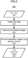
- FIG. 2 shows a non-limiting example of a flow chart for performing the methods described herein, according to an embodiment of the present disclosure.
- the parameters/type of the penalty can depend on a spatial variations in the activity level, which is derived from the reconstructed image itself, allowing, e.g., more smoothing in regions of low activity and less smoothing and/or more edge enhancement in regions of greater activity.
- the penalty type, one or more penalty parameter e.g., a parameter controlling the edge enhancement penalty/shape
- the penalty strength can each be based on an initially estimated activity map (e.g., a preliminary reconstructed PET image).
- the optimal degree of penalty can depend the level of activity in a given image.
- the penalty parameter can be position dependent (e.g., organ-activity dependent) in addition to being PET scan dependent (e.g., image and/or acquisition time dependent).
- method 200 begins at step 210 by obtaining emission data 205 for tomographic reconstruction of a PET image.
- incident radiation e.g. gamma rays
- scintillation photons which are in turn converted to photoelectrons by photodetectors.
- the photoelectron signals from the photodetectors can be amplified, pulse-shaped, filtered, and otherwise pre-conditioned and processed before being digitized using a data acquisition system (DAS) as time, energy, and position information for respective counts and/or coincidence pairs and then stored to a non-transitory computer readable memory.
- DAS data acquisition system
- the PET data 205 can then be obtained from the memory in preparation for tomographic image reconstruction.
- the PET data 205 can be counts that are pre-processed, calibrated, and/or arranged into a sinogram format (e.g., a histogram of counts).
- pre-processing can include position corrections, energy corrections, timing corrections, etc.
- the emission data 205 can be corrected for sensitivity using various calibration and geometric factors.
- the pre-processing can include corrections for a detector offset and gain, variations in quantum efficiency in the detectors, etc. Further, these corrections can be based on calibration data, empirical, and known parameters.
- an initial PET image is reconstructed.
- the PET data 205 is used to reconstruct an image of radioactivity level (e.g., tracer density) as a function of voxel position.
- the image reconstruction can be performed using a back-projection method, a filtered back-projection method, a Fourier-transform-based image reconstruction method, an iterative image reconstruction method, a matrix-inversion image reconstruction method, a statistical image reconstruction method, a list-mode method, or other reconstruction method or combination thereof, as would be understood as a person of ordinary skill in the art.
- the activity map is determined from the initial PET image, but the activity map is not necessarily identical with the initial PET image.
- An ordered subset expectation maximization (OSEM) iteration can then be performed on the summed dynamic sinogram data 100a to estimate the activity map x OSEM .
- the fine resolution is not required for the spatial variation of the penalty.
- the activity map can be based on a smoothed or coarse-grained version of the initial PET image in which a low-spatial-frequency filter has been applied to the initial PET image.
- other denoising methods could be applied to mitigate the effect of noise on the activity map and the spatial variation of the penalty.
- Exemplary denoising methods include linear smoothing filters, anisotropic diffusion, non-local means, or nonlinear filters.
- Linear smoothing filters remove noise by convolving the original image with a mask that represents a low-pass filter or smoothing operation.
- the Gaussian mask comprises elements determined by a Gaussian function. This convolution brings the value of each pixel/voxel into closer agreement with the values of its neighbors.
- Anisotropic diffusion removes noise while preserving sharp edges by evolving an image under a smoothing partial differential equation similar to the heat equation.
- a median filter is an example of a nonlinear filter and, if properly designed, a nonlinear filter can also preserve edges and avoid blurring.
- the median filter is one example of a rank-conditioned rank-selection (RCRS) filter, which can be applied to remove salt and pepper noise from an image without introducing significant blurring artifacts.
- a filter using a total-variation (TV) minimization regularization term can be applied if imaged region supports an assumption of uniformity over large areas that are demarked by sharp boundaries between the uniform areas.
- a TV filter is another example of a nonlinear filter.
- non-local means filtering is an exemplary method of determining denoised pixels/voxels using a weighted average over similar patches within the images.
- the parametric images 100c can be estimated while incorporating the penalty function.
- the dynamic images 100b can be analyzed to generate the TAC for each dynamic image 100b.
- Final parametric images 240 can be generated by performing Patlak analysis on the TAC for the each dynamic image 100b in a pixel-by-pixel (or voxel-by-voxel) manner to estimate the final parametric images 240.
- the Patlak parametric images can be estimated pixel-by-pixel (or voxel-by-voxel) from the frame-by-frame reconstructed images x ⁇ , for example, using a least squares estimation.
- the Patlak parametric images can be described by ⁇ (the parametric images of the Patlak slope) and b (the parametric images of the Patlak intercept).
- the penalty can be described by ⁇ ⁇ and ⁇ b , the parameters controlling the degree of penalty on the parametric images.
- the spatial variation in the penalty arises from the regularization of ⁇ n , ⁇ ⁇ , and ⁇ b being position dependent.
- the position dependence of the penalty terms ⁇ n , ⁇ ⁇ , and ⁇ b can be referred to as a ⁇ -map, and can be represented as ⁇ j in which the subscript j is the index of the j th voxel/pixel in the reconstructed PET image x OSEM .
- f ( ⁇ ) can include smoothing, low-frequency filtering, and/or denoising, as discussed above.
- either image-derived or population-based blood input function can be used for Patlak fitting. It may be appreciated that any globally convergent numerical optimization algorithm can be used to find the optimizer of the final cost function (with convex penalties).
- the method 200 provides different penalty parameters in dynamic PET reconstruction, both for frame-by-frame reconstruction of the dynamic images 100b and the Patlak fitting for the generation of the parametric images 100c.
- the method 200 utilizes spatially varying penalty parameter tuning guided by the static reconstruction of the data itself.
- the processor 370 generates at least one parametric image using the plurality of dynamic sinograms and an objective function including a penalty term determined based on the activity map.
- the method 200 thus provides a user full flexibility in choosing the smoothing and edge-preservation strengths according to any desired function of activity estimates, which allows patient-adaptive optimization of reconstruction methods for specific tasks in routine clinical settings.
- FIGS 3A and 3B show a non-limiting example of a PET scanner 300 that can implement the methods 100 and 200.
- the PET scanner 300 includes a number of gamma-ray detectors (GRDs) (e.g., GRD1, GRD2, through GRDN) that are each configured as rectangular detector modules.
- the detector ring includes 40 GRDs.
- Each GRD can include a two-dimensional array of individual detector crystals, which absorb gamma radiation and emit scintillation photons.
- the scintillation photons can be detected by a two-dimensional array of photomultiplier tubes (PMTs) that are also arranged in the GRD.
- a light guide can be disposed between the array of detector crystals and the PMTs.
- the scintillation photons can be detected by an array a silicon photomultipliers (SiPMs), and each individual detector crystals can have a respective SiPM.
- SiPMs silicon photomultipliers
- Each photodetector e.g., PMT or SiPM
- the photons emitted from one detector crystal can be detected by more than one photodetector, and, based on the analog signal produced at each photodetector, the detector crystal corresponding to the detection event can be determined using Anger logic and crystal decoding, for example.
- FIG 3B shows a schematic view of a PET scanner system having gamma-ray (gamma-ray) photon counting detectors (GRDs) arranged to detect gamma-rays emitted from an object OBJ.
- the GRDs can measure the timing, position, and energy corresponding to each gamma-ray detection.
- the gamma-ray detectors are arranged in a ring, as shown in Figures 3A and 3B .
- the detector crystals can be scintillator crystals, which have individual scintillator elements arranged in a two-dimensional array and the scintillator elements can be any known scintillating material.
- the PMTs can be arranged such that light from each scintillator element is detected by multiple PMTs to enable Anger arithmetic and crystal decoding of scintillation event.
- Figure 3B shows an example of the arrangement of the PET scanner 300, in which the object OBJ to be imaged rests on a table 316 and the GRD modules GRD1 through GRDN are arranged circumferentially around the object OBJ and the table 316.
- the GRDs can be fixedly connected to a circular component 320 that is fixedly connected to the gantry 340.
- the gantry 340 houses many parts of the PET imager.
- the gantry 340 of the PET imager also includes an open aperture through which the object OBJ and the table 316 can pass, and gamma-rays emitted in opposite directions from the object OBJ due to an annihilation event can be detected by the GRDs and timing and energy information can be used to determine coincidences for gamma-ray pairs.
- circuitry and hardware is also shown for acquiring, storing, processing, and distributing gamma-ray detection data.
- the circuitry and hardware include: a processor 370, a network controller 374, a memory 378, and a data acquisition system (DAS) 376.
- the PET imager also includes a data channel that routes detection measurement results from the GRDs to the DAS 376, the processor 370, the memory 378, and the network controller 374.
- the DAS 376 can control the acquisition, digitization, and routing of the detection data from the detectors. In one implementation, the DAS 376 controls the movement of the bed 316.
- the processor 370 performs functions including reconstructing images from the detection data, pre-reconstruction processing of the detection data, and post-reconstruction processing of the image data, as discussed herein.
- the processor 370 can be configured to perform various steps of methods 100 and/or 200 described herein and variations thereof.
- the processor 370 can include a CPU that can be implemented as discrete logic gates, as an Application Specific Integrated Circuit (ASIC), a Field Programmable Gate Array (FPGA) or other Complex Programmable Logic Device (CPLD).
- An FPGA or CPLD implementation may be coded in VHDL, Verilog, or any other hardware description language and the code may be stored in an electronic memory directly within the FPGA or CPLD, or as a separate electronic memory.
- the memory may be non-volatile, such as ROM, EPROM, EEPROM or FLASH memory.
- the memory can also be volatile, such as static or dynamic RAM, and a processor, such as a microcontroller or microprocessor, may be provided to manage the electronic memory as well as the interaction between the FPGA or CPLD and the memory.
- the CPU in the processor 370 can execute a computer program including a set of computer-readable instructions that perform various steps of method 100 and/or method 200, the program being stored in any of the above-described non-transitory electronic memories and/or a hard disk drive, CD, DVD, FLASH drive or any other known storage media.
- the computer-readable instructions may be provided as a utility application, background daemon, or component of an operating system, or combination thereof, executing in conjunction with a processor, such as a Xenon processor from Intel of America or an Opteron processor from AMD of America and an operating system, such as Microsoft VISTA, UNIX, Solaris, LINUX, Apple, MAC-OS and other operating systems known to those skilled in the art.
- CPU can be implemented as multiple processors cooperatively working in parallel to perform the instructions.
- the memory 378 can be a hard disk drive, CD-ROM drive, DVD drive, FLASH drive, RAM, ROM or any other electronic storage known in the art.
- the network controller 374 can interface between the various parts of the PET imager. Additionally, the network controller 374 can also interface with an external network.
- the external network can be a public network, such as the Internet, or a private network such as an LAN or WAN network, or any combination thereof and can also include PSTN or ISDN sub-networks.
- the external network can also be wired, such as an Ethernet network, or can be wireless such as a cellular network including EDGE, 3G and 4G wireless cellular systems.
- the wireless network can also be WiFi, Bluetooth, or any other wireless form of communication that is known.
Landscapes
- Physics & Mathematics (AREA)
- General Physics & Mathematics (AREA)
- Engineering & Computer Science (AREA)
- Theoretical Computer Science (AREA)
- Nuclear Medicine (AREA)
Abstract

Description
- Embodiments described herein relate generally to a medical image processing apparatus and a medical image processing method.
- The background description provided herein is for the purpose of generally presenting the context of the disclosure. Work of the presently named inventors, to the extent the work is described in this background section, as well as aspects of the description that may not otherwise qualify as prior art at the time of filing, are neither expressly nor impliedly admitted as prior art against the present disclosure.
- Positron emission tomography (PET) is a functional imaging modality that is capable of imaging biochemical processes in humans or animals through the use of radioactive tracers. In PET imaging, a tracer agent is introduced into the patient to be imaged via injection, inhalation, or ingestion. After administration, the physical and bio-molecular properties of the agent cause it to concentrate at specific locations in the patient's body. The actual spatial distribution of the agent, the intensity of the region of accumulation of the agent, and the kinetics of the process from administration to its eventual elimination are all factors that may have clinical significance.
- The most commonly used tracer for PET studies is fluorodeoxyglucose (FDG), which allows the study of glucose metabolism, a process that is up-regulated substantially in cancerous tissue. PET scans with FDG are increasingly being used for staging, restaging, and treatment monitoring for cancer patients with different types of tumors.
- During this process, a tracer attached to the agent will emit positrons. When an emitted positron collides with an electron, an annihilation event occurs, wherein the positron and electron are combined. Most of the time, an annihilation event produces two gamma rays (at 511 keV) traveling at substantially 180 degrees apart.
- To reconstruct the spatio-temporal distribution of the tracer via tomographic reconstruction principles, each detected event is characterized for its energy (i.e., amount of light generated), its location, and its timing. By detecting the two gamma rays, and drawing a line between their locations, i.e., the line-of-response (LOR), one can determine the likely location of the original disintegration. While this process will only identify a line of possible interaction, by accumulating a large number of those lines, tomographic reconstruction can be used to estimate the original distribution. Thus, the LOR for coincidence pairs and the timing information is used to reconstruct a tomographic image of the radioactivity, yielding clinical information.
- However, the potential of PET is under-utilized by current routine static imaging protocols, which mainly examine the tracer concentration at a single time point. It is reasonable to expect that dynamic PET, which follows the tracer uptake over a period of time, would provide more accurate information than static PET. Also, the recent development of PET scanners with increased axial field-of-view (FOV) makes the whole-body dynamic imaging possible for routine clinical practice.
- One popular method to analyze dynamic PET data is the Patlak graphical model. The slope of the Patlak plot and the corresponding parametric images has proven to be an effective quantitative index for characterizing kinetic properties of many PET tracers. In some methods, a penalty function may be applied to the Patlak fitting. Properly tuning the penalty strength and penalty parameters to fully take advantage of the spatial-temporal information in dynamic PET data is a challenge and contributes to achieving desired performances in reconstructed images. Thus, a method including an optimal penalty function for dynamic PET that is able to exploit spatial information embed in dynamic PET data to suppress noise while preserving image features (e.g. fine structures and sharp edges around organ boundaries) in the parametric images is desired.
- A medical image procesing apparatus according to at least one aspect of the present disclosure comprises processing circuitry. The processing circuitry obtains a plurality of dynamic sinograms, each of the plurality of dynamic sinograms representing detection events of gamma rays at a plurality of scintillator elements, sums the plurality of dynamic sinograms to generate an activity map based on a radioactivity level of the gamma rays, and generates, using the plurality of dynamic sinograms and the activity map, at least one parametric image.
- The circuitry may reconstruct, using the plurality of dynamic sinograms, a plurality of dynamic images, each of the plurality of dynamic images corresponding to a dynamic sinogram of the plurality of dynamic sinograms, and generate a time activity curve for the each of the plurality of dynamic images, and the at least one parametric image is corrected using the activity map and the time activity curve for the each of the plurality of dynamic images.
- The circuitry may further generate the at least one parametric image using an objective function including a penalty term, wherein the penalty term includes one or more spatially-varying smoothing strength determined from the activity map.
- The penalty term may include a first parameter controlling the degree of penalty based on a Patlak slope of the time activity curve, and a second parameter controlling the degree of penalty based on a Patlak intercept of the time activity curve.
- The circuitry may further generate the at least one parametric image using an objective function including a penalty term, wherein the penalty term includes an edge-preserving potential function that has a shape based on the activity map.
- The circuitry may further generate the at least one parametric image using a voxel-by-voxel parametric fitting for the each of the plurality of dynamic sinograms.
- The medical image processing apparatus may further comprise a detector including the plurality of scintillator elements configured to detect the gamma rays generated from a tracer.
- A positron emission tompgraphy apparatus according to at least one aspect of to at least one aspect of the present disclosure comprises the medical image processing apparatus and the detector.
- The activity map may be generated using an ordered-subset expectation maximization (OSEM) method, which is iteratively repeated until a predetermined stopping criteria is reached.
- The dynamic sinograms may be obtained over a predetermined duration of time at predetermined intervals.
- The circuitry may further segment the activity map based on types of organs represented therein, and generate the at least one parametric image, wherein the penalty term is based on the segmentation of the activity map.
- The at least one parametric image may be an image corresponding to a slope and an intercept of a time activity curve.
- A medical image processing apparatus according to an aspect of the present disclosure comprises processing circuitry (a processor). The processing circuitry obtains a plurality of dynamic sinograms, each of the plurality of dynamic sinograms representing detection events of gamma rays at a plurality of scintillator elements, generates an activity map based on a radioactivity level of the gamma rays and the plurality of dynamic sinograms, and generates, using the plurality of dynamic sinograms and a objective function including a penalty term determined based on the activity map, at least one parametric image.
- A meical image processing method according to a present disclosure comprises obtaining a plurality of dynamic sinograms, each dynamic sinogram representing detection events of gamma rays at a plurality of scintillator elements; summing the plurality of dynamic sinograms to generate an activity map based on a radioactivity level of the gamma rays; and generating, using the plurality of dynamic sinograms and the activity map, at least one parametric image.
- The method may further comprises generating a time activity curve for the each of the plurality of dynamic images, wherein the at least one parametric image is generated using the activity map and the time activity curve for the each of the plurality of dynamic images.
- The generating the at least one parametric image may further include using an objective function including a penalty term, the penalty term including one or more spatially-varying smoothing strength determined from the activity map.
- The penalty term may further include a first parameter controlling the degree of penalty based on a Patlak slope of the time activity curve, and a second parameter controlling the degree of penalty based on a Patlak intercept of the time activity curve.
- The generating the at least one parametric image may further includes using an objective function including a penalty term, wherein the penalty term includes an edge-preserving potential function that has a shape based on the activity map.
- The generating the at least one parametric image may further include using a voxel-by-voxel parametric fitting for the each of the plurality of dynamic sinograms.
- The parametric fitting may use a least squares estimation.
- The activity map may be generated using an ordered-subset expectation maximization (OSEM) method, which is iteratively repeated until a predetermined stopping criteria is reached.
- The method may further comprise segmenting the activity map based on types of organs represented therein; and generating the at least one parametric image, wherein the penalty term is based on the segmentation of the activity map.
- A computer-readable storage medium according to an embodiment includes executable instructions, which when executed by circuitry, cause the circuitry to perform the method comprising obtaining a plurality of dynamic sinograms, each dynamic sinogram representing detection events of gamma rays at a plurality of scintillator elements; summing the plurality of dynamic sinograms to generate an activity map based on a radioactivity level of the gamma rays; reconstructing, using the plurality of dynamic sinograms, a plurality of dynamic images, each of the plurality of dynamic images corresponding to one of the each of the plurality of dynamic sinograms; and generating, using the plurality of dynamic sinograms and the activity map, at least one parametric image.
-
-
FIG. 1 shows reconstruction of dynamic emission images and parametric fitting of the dynamic emission images to generate parametric images, according to an embodiment of the present disclosure. -
FIG. 2 shows a non-limiting example of a flow chart for a method of imaging, according to an embodiment of the present disclosure. -
FIG. 3A shows a perspective view of a positron-emission tomography (PET) scanner, according to an embodiment of the present disclosure. -
FIG. 3B shows a schematic view of a PET scanner, according to an embodiment of the present disclosure. - The following disclosure provides many different embodiments, or examples, for implementing different features of the provided subject matter. Specific examples of components and arrangements are described below to simplify the present disclosure. These are, of course, merely examples and are not intended to be limiting. For example, the formation of a first feature over or on a second feature in the description that follows may include embodiments in which the first and second features are formed in direct contact, and may also include embodiments in which additional features may be formed between the first and second features, such that the first and second features may not be in direct contact. In addition, the present disclosure may repeat reference numerals and/or letters in the various examples. This repetition is for the purpose of simplicity and clarity and does not in itself dictate a relationship between the various embodiments and/or configurations discussed. Further, spatially relative terms, such as "top," "bottom," "beneath," "below," "lower," "above," "upper" and the like, may be used herein for ease of description to describe one element or feature's relationship to another element(s) or feature(s) as illustrated in the figures. The spatially relative terms are intended to encompass different orientations of the device in use or operation in addition to the orientation depicted in the figures. The apparatus may be otherwise oriented (rotated 90 degrees or at other orientations) and the spatially relative descriptors used herein may likewise be interpreted accordingly.
- The order of discussion of the different steps as described herein has been presented for clarity sake. In general, these steps can be performed in any suitable order. Additionally, although each of the different features, techniques, configurations, etc. herein may be discussed in different places of this disclosure, it is intended that each of the concepts can be executed independently of each other or in combination with each other. Accordingly, the present invention can be embodied and viewed in many different ways.
- Some methods for generating parametric images during dynamic PET include reconstructing dynamic emission images from dynamic sinogram data and then perform Patlak analysis on the time activity curves (TAC) to generate parametric images, which can be referred to as an indirect method. However, the indirect method can be sensitive to the noise which greatly degrades the image quality in the final parametric images.
- In some methods, a direct reconstruction can reconstruct the Patlak parametric images from dynamic sinogram data by incorporating the Patlak model into the image reconstruction procedure. Unfortunately, the direct methods can prove more complex and time-consuming than the indirect method which can limit its practical use. For example, a quadratic penalty can be applied to a frame-by-frame reconstruction and the Patlak parametric image estimations to maximize lesion detection performance. However, this method can limit the freedom to tune the penalty strength according to any other rule and may not include the option to change the penalty type/parameters from one region to another.
- As described herein, a regularization method is incorporated in dynamic PET reconstruction including regularization/penalty parameter selection where a spatially variant map can be determined for the penalty type, parameter, and strength based on an estimated activity map of combined dynamic scan data.
- The methods described herein can improve the quality of PET images by spatially varying the penalty function during a parametric fitting based on an activity-level mapping derived from a reconstructed image. In an embodiment, the method utilizes activity estimates by reconstructing measured emission data summed over a predetermined scan duration to guide a smoothing strength in dynamic reconstruction. The optimal degree of penalty can depend the level of activity in a given image. That is, different images with different amounts of activity can benefit from having different degrees of penalty. Further, this idea can carryover and apply to different regions within an image. That is, a region with a greater level of activity can benefit from a different degree of penalty than a region with a lesser level of activity. The smoothing strength based on static reconstruction can be applied both in the frame-by-frame reconstruction, and the voxel- or pixel-based Patlak model fitting. While the penalty type and parameters, such as the edge-preservation parameter, can also be changed, the parameter of interest is the smoothing strength and how it can be changed based on activity, and imposed on dynamic parametric images. Thus, the method allows scaling of the penalty term according to any desired function of activity.
- In an embodiment, the activity-dependent smoothing parameter scaling can also be used in combination with other smoothing parameter scaling rules such as attenuation-dependent scaling. Notably, either image-derived or population-based blood input functions can be used with this method.
-
FIG. 1 shows reconstruction ofdynamic emission images 100b (herein referred to as "dynamic images 100b") and parametric fitting of theemission images 100b to generateparametric images 100c, according to an embodiment of the present disclosure. As previously described, thedynamic images 100b can be reconstructed frame-by-frame fromdynamic sinogram data 100a. Theparametric images 100c can be generated by performing Patlak analysis on the TAC pixel-by-pixel (or voxel-by-voxel) to estimate theparametric images 100c. This indirect method is sensitive to the noise, which degrades the image quality in theparametric images 100c since the spatial information embedded in the dynamic PET data is disregarded in the Patlak analysis. - In some embodiments, given a set of measured
dynamic sinogram data 100a including T frames where


- With the frame-by-frame reconstructed images x̂ =


- In some embodiments, the penalty function can be a patch-based edge-preserving penalty function, which uses neighboring patches instead of individual pixels/voxels to compute the penalty as exemplified by the expression:


- The penalty function discussed above is straightforward to generalize and can be applied for both pairwise and patch-based penalties, as would be understood by a person of ordinary skill in the art. Other penalty functions can be used without departing from the spirit of the methods described herein, as would be understood by a person of ordinary skill in the art. For example, the total variation minimization (TV) penalty function penalizes solutions for which the total variation is large. TV regularization is one non-limiting example of many different types of regularization penalties that can be used without departing from the spirit of the methods described herein. Other non-limiting examples of regularization penalties included, e.g., a Huber penalty, a broken parabola penalty, quadratic penalties, non-quadratic penalties, etc.
- By increasing the magnitude of the penalty parameter βn , noise in the reconstructed image is suppressed while reducing resolution. Accordingly, regions having lower activity can benefit from a higher degree of smoothing because the count statistics in these regions make them more prone to a low signal-to-noise ratio (SNR) (i.e., relatively high noise levels) and fine resolution in these regions is likely not required. For example, higher tracer densities and activity levels are generally found near the region of interest (e.g., due to higher metabolic rates of a lesion). Thus, image reconstruction in which lower activity corresponds to a larger penalty parameter βn can be beneficial.
- Additionally, where the activity is high, a lower penalty parameter βn can prevent reduced resolution without sacrificing image quality because the signal is already large compared to the noise. Thus, in these regions of high activity, the SNR can be already sufficiently high without the increased smoothing provided by a large value for the penalty parameter βn .
-
FIG. 2 shows a non-limiting example of a flow chart for performing the methods described herein, according to an embodiment of the present disclosure. In an embodiment, the parameters/type of the penalty can depend on a spatial variations in the activity level, which is derived from the reconstructed image itself, allowing, e.g., more smoothing in regions of low activity and less smoothing and/or more edge enhancement in regions of greater activity. In some embodiments, the penalty type, one or more penalty parameter (e.g., a parameter controlling the edge enhancement penalty/shape), and the penalty strength can each be based on an initially estimated activity map (e.g., a preliminary reconstructed PET image). The optimal degree of penalty can depend the level of activity in a given image. That is, different images with different amounts of activity can benefit from having different degrees of penalty. Further, this idea can carryover and apply to different regions within an image. That is, a region with a greater level of activity can benefit from a different degree of penalty than a region with a lesser level of activity. Since different organs have different background activity levels, the penalty parameter can be position dependent (e.g., organ-activity dependent) in addition to being PET scan dependent (e.g., image and/or acquisition time dependent). - In
FIG. 2 ,method 200 begins atstep 210 by obtainingemission data 205 for tomographic reconstruction of a PET image. For example, incident radiation (e.g. gamma rays) incident on an array of scintillator crystals are converted to scintillation photons, which are in turn converted to photoelectrons by photodetectors. Further, in some embodiments, the photoelectron signals from the photodetectors can be amplified, pulse-shaped, filtered, and otherwise pre-conditioned and processed before being digitized using a data acquisition system (DAS) as time, energy, and position information for respective counts and/or coincidence pairs and then stored to a non-transitory computer readable memory. ThePET data 205 can then be obtained from the memory in preparation for tomographic image reconstruction. - In some embodiments, the
PET data 205 can be counts that are pre-processed, calibrated, and/or arranged into a sinogram format (e.g., a histogram of counts). In some embodiments, pre-processing can include position corrections, energy corrections, timing corrections, etc. Further, theemission data 205 can be corrected for sensitivity using various calibration and geometric factors. Moreover, the pre-processing can include corrections for a detector offset and gain, variations in quantum efficiency in the detectors, etc. Further, these corrections can be based on calibration data, empirical, and known parameters. - In
step 220, an initial PET image is reconstructed. For example, thePET data 205 is used to reconstruct an image of radioactivity level (e.g., tracer density) as a function of voxel position. The image reconstruction can be performed using a back-projection method, a filtered back-projection method, a Fourier-transform-based image reconstruction method, an iterative image reconstruction method, a matrix-inversion image reconstruction method, a statistical image reconstruction method, a list-mode method, or other reconstruction method or combination thereof, as would be understood as a person of ordinary skill in the art. - In
step 220, the activity map is determined from the initial PET image, but the activity map is not necessarily identical with the initial PET image. In an embodiment, given measureddynamic sinogram data 100a
dynamic sinogram data 100a can be summed together into y = y 1 + y 2 + ··· + yT. An ordered subset expectation maximization (OSEM) iteration can then be performed on the summeddynamic sinogram data 100a to estimate the activity map xOSEM. - In some embodiments, the fine resolution is not required for the spatial variation of the penalty. For example, the activity map can be based on a smoothed or coarse-grained version of the initial PET image in which a low-spatial-frequency filter has been applied to the initial PET image. Also, other denoising methods could be applied to mitigate the effect of noise on the activity map and the spatial variation of the penalty.
- Exemplary denoising methods include linear smoothing filters, anisotropic diffusion, non-local means, or nonlinear filters. Linear smoothing filters remove noise by convolving the original image with a mask that represents a low-pass filter or smoothing operation. For example, the Gaussian mask comprises elements determined by a Gaussian function. This convolution brings the value of each pixel/voxel into closer agreement with the values of its neighbors. Anisotropic diffusion removes noise while preserving sharp edges by evolving an image under a smoothing partial differential equation similar to the heat equation. A median filter is an example of a nonlinear filter and, if properly designed, a nonlinear filter can also preserve edges and avoid blurring. The median filter is one example of a rank-conditioned rank-selection (RCRS) filter, which can be applied to remove salt and pepper noise from an image without introducing significant blurring artifacts. Additionally, a filter using a total-variation (TV) minimization regularization term can be applied if imaged region supports an assumption of uniformity over large areas that are demarked by sharp boundaries between the uniform areas. A TV filter is another example of a nonlinear filter. Moreover, non-local means filtering is an exemplary method of determining denoised pixels/voxels using a weighted average over similar patches within the images.
- In
step 230, theparametric images 100c can be estimated while incorporating the penalty function. In an embodiment, thedynamic images 100b can be analyzed to generate the TAC for eachdynamic image 100b. Final parametric images 240 can be generated by performing Patlak analysis on the TAC for the eachdynamic image 100b in a pixel-by-pixel (or voxel-by-voxel) manner to estimate the final parametric images 240. The Patlak parametric images can be estimated pixel-by-pixel (or voxel-by-voxel) from the frame-by-frame reconstructed images x̂, for example, using a least squares estimation. - The Patlak parametric images can be described by κ (the parametric images of the Patlak slope) and b (the parametric images of the Patlak intercept). The penalty can be described by βκ and βb , the parameters controlling the degree of penalty on the parametric images. In some embodiments, the spatial variation in the penalty arises from the regularization of βn , βκ , and βb being position dependent. The position dependence of the penalty terms βn , βκ , and βb can be referred to as a β -map, and can be represented as βj in which the subscript j is the index of the jth voxel/pixel in the reconstructed PET image xOSEM. The β -map can be scaled according to βj = f(xjOSEM ) for each pixel/voxel j, where f(·) can be any user-selected function. For example, the user-selected function f(·) can include smoothing, low-frequency filtering, and/or denoising, as discussed above.
- The developed β -map can be applied in the regularization of frame-by-frame reconstruction where for each frame n, βnj = fn (xjOSEM ) and Patlak model fitting where βκj = fκ (xjOsEM ), βbj = fb (xjOSEM ). The same scaling rule can also be applied to δ , the penalty parameter that controls the shape of the potential function and the extent of edge-preservation, such that δj = g(xjOSEM ) and applied in the frame-by-frame reconstruction and Patlak fitting. Notably, either image-derived or population-based blood input function can be used for Patlak fitting. It may be appreciated that any globally convergent numerical optimization algorithm can be used to find the optimizer of the final cost function (with convex penalties).
- Advantageously, the
method 200 provides different penalty parameters in dynamic PET reconstruction, both for frame-by-frame reconstruction of thedynamic images 100b and the Patlak fitting for the generation of theparametric images 100c. Notably, themethod 200 utilizes spatially varying penalty parameter tuning guided by the static reconstruction of the data itself. In other words, theprocessor 370 generates at least one parametric image using the plurality of dynamic sinograms and an objective function including a penalty term determined based on the activity map. Themethod 200 thus provides a user full flexibility in choosing the smoothing and edge-preservation strengths according to any desired function of activity estimates, which allows patient-adaptive optimization of reconstruction methods for specific tasks in routine clinical settings. -
Figures 3A and3B show a non-limiting example of aPET scanner 300 that can implement themethods 100 and 200. ThePET scanner 300 includes a number of gamma-ray detectors (GRDs) (e.g., GRD1, GRD2, through GRDN) that are each configured as rectangular detector modules. According to one implementation, the detector ring includes 40 GRDs. In another implementation, there are 48 GRDs, and the higher number of GRDs is used to create a larger bore size for thePET scanner 300. - Each GRD can include a two-dimensional array of individual detector crystals, which absorb gamma radiation and emit scintillation photons. The scintillation photons can be detected by a two-dimensional array of photomultiplier tubes (PMTs) that are also arranged in the GRD. A light guide can be disposed between the array of detector crystals and the PMTs.
- Alternatively, the scintillation photons can be detected by an array a silicon photomultipliers (SiPMs), and each individual detector crystals can have a respective SiPM.
- Each photodetector (e.g., PMT or SiPM) can produce an analog signal that indicates when scintillation events occur, and an energy of the gamma ray producing the detection event. Moreover, the photons emitted from one detector crystal can be detected by more than one photodetector, and, based on the analog signal produced at each photodetector, the detector crystal corresponding to the detection event can be determined using Anger logic and crystal decoding, for example.
-
Figure 3B shows a schematic view of a PET scanner system having gamma-ray (gamma-ray) photon counting detectors (GRDs) arranged to detect gamma-rays emitted from an object OBJ. The GRDs can measure the timing, position, and energy corresponding to each gamma-ray detection. In one implementation, the gamma-ray detectors are arranged in a ring, as shown inFigures 3A and3B . The detector crystals can be scintillator crystals, which have individual scintillator elements arranged in a two-dimensional array and the scintillator elements can be any known scintillating material. The PMTs can be arranged such that light from each scintillator element is detected by multiple PMTs to enable Anger arithmetic and crystal decoding of scintillation event. -
Figure 3B shows an example of the arrangement of thePET scanner 300, in which the object OBJ to be imaged rests on a table 316 and the GRD modules GRD1 through GRDN are arranged circumferentially around the object OBJ and the table 316. The GRDs can be fixedly connected to acircular component 320 that is fixedly connected to thegantry 340. Thegantry 340 houses many parts of the PET imager. Thegantry 340 of the PET imager also includes an open aperture through which the object OBJ and the table 316 can pass, and gamma-rays emitted in opposite directions from the object OBJ due to an annihilation event can be detected by the GRDs and timing and energy information can be used to determine coincidences for gamma-ray pairs. - In
Figure 3B , circuitry and hardware is also shown for acquiring, storing, processing, and distributing gamma-ray detection data. The circuitry and hardware include: aprocessor 370, anetwork controller 374, amemory 378, and a data acquisition system (DAS) 376. The PET imager also includes a data channel that routes detection measurement results from the GRDs to theDAS 376, theprocessor 370, thememory 378, and thenetwork controller 374. TheDAS 376 can control the acquisition, digitization, and routing of the detection data from the detectors. In one implementation, theDAS 376 controls the movement of thebed 316. Theprocessor 370 performs functions including reconstructing images from the detection data, pre-reconstruction processing of the detection data, and post-reconstruction processing of the image data, as discussed herein. - The
processor 370 can be configured to perform various steps of methods 100 and/or 200 described herein and variations thereof. Theprocessor 370 can include a CPU that can be implemented as discrete logic gates, as an Application Specific Integrated Circuit (ASIC), a Field Programmable Gate Array (FPGA) or other Complex Programmable Logic Device (CPLD). An FPGA or CPLD implementation may be coded in VHDL, Verilog, or any other hardware description language and the code may be stored in an electronic memory directly within the FPGA or CPLD, or as a separate electronic memory. Further, the memory may be non-volatile, such as ROM, EPROM, EEPROM or FLASH memory. The memory can also be volatile, such as static or dynamic RAM, and a processor, such as a microcontroller or microprocessor, may be provided to manage the electronic memory as well as the interaction between the FPGA or CPLD and the memory. - Alternatively, the CPU in the
processor 370 can execute a computer program including a set of computer-readable instructions that perform various steps of method 100 and/ormethod 200, the program being stored in any of the above-described non-transitory electronic memories and/or a hard disk drive, CD, DVD, FLASH drive or any other known storage media. Further, the computer-readable instructions may be provided as a utility application, background daemon, or component of an operating system, or combination thereof, executing in conjunction with a processor, such as a Xenon processor from Intel of America or an Opteron processor from AMD of America and an operating system, such as Microsoft VISTA, UNIX, Solaris, LINUX, Apple, MAC-OS and other operating systems known to those skilled in the art. Further, CPU can be implemented as multiple processors cooperatively working in parallel to perform the instructions. - The
memory 378 can be a hard disk drive, CD-ROM drive, DVD drive, FLASH drive, RAM, ROM or any other electronic storage known in the art. - The
network controller 374, such as an Intel Ethernet PRO network interface card from Intel Corporation of America, can interface between the various parts of the PET imager. Additionally, thenetwork controller 374 can also interface with an external network. As can be appreciated, the external network can be a public network, such as the Internet, or a private network such as an LAN or WAN network, or any combination thereof and can also include PSTN or ISDN sub-networks. The external network can also be wired, such as an Ethernet network, or can be wireless such as a cellular network including EDGE, 3G and 4G wireless cellular systems. The wireless network can also be WiFi, Bluetooth, or any other wireless form of communication that is known. - In the preceding description, specific details have been set forth, such as a particular geometry of a processing system and descriptions of various components and processes used therein. It should be understood, however, that techniques herein may be practiced in other embodiments that depart from these specific details, and that such details are for purposes of explanation and not limitation. Embodiments disclosed herein have been described with reference to the accompanying drawings. Similarly, for purposes of explanation, specific numbers, materials, and configurations have been set forth in order to provide a thorough understanding. Nevertheless, embodiments may be practiced without such specific details. Components having substantially the same functional constructions are denoted by like reference characters, and thus any redundant descriptions may be omitted.
- Various techniques have been described as multiple discrete operations to assist in understanding the various embodiments. The order of description should not be construed as to imply that these operations are necessarily order dependent. Indeed, these operations need not be performed in the order of presentation. Operations described may be performed in a different order than the described embodiment. Various additional operations may be performed and/or described operations may be omitted in additional embodiments.
- While certain embodiments have been described, these embodiments have been presented by way of example only, and are not intended to limit the scope of the inventions. Indeed, the novel embodiments described herein may be embodied in a variety of other forms; furthermore, various omissions, substitutions and changes in the form of the embodiments described herein may be made without departing from the scope of the invention as defined by the appended claims.
Claims (11)
- A medical image processing apparatus, comprising:
processing circuitry (370) configured toobtain a plurality of dynamic sinograms (100a), each of the plurality of dynamic sinograms (100a) representing detection events of gamma rays at a plurality of scintillator elements,sum the plurality of dynamic sinograms to generate an activity map based on a radioactivity level of the gamma rays,andgenerate, using the plurality of dynamic sinograms (100a) and the activity map, at least one parametric image (100c) . - The medical image processing apparatus of Claim 1, wherein the circuitry (370) is further configured to reconstruct, using the plurality of dynamic sinograms (100a), a plurality of dynamic images (100b), each of the plurality of dynamic images (100b) corresponding to a dynamic sinogram (100a) of the plurality of dynamic sinograms (100a), and generate a time activity curve for the each of the plurality of dynamic images (100b), and the at least one parametric image (100c) is corrected using the activity map and the time activity curve for the each of the plurality of dynamic images (100b).
- The medical image procesing apparatus of Claim 2, wherein the circuitry (370) is further configured to generate the at least one parametric image (100c) using an objective function including a penalty term, wherein the penalty term includes one or more spatially-varying smoothing strength determined from the activity map.
- The medical image processing apparatus of Claim 3, wherein the penalty term includes a first parameter controlling the degree of penalty based on a Patlak slope of the time activity curve, and a second parameter controlling the degree of penalty based on a Patlak intercept of the time activity curve.
- The medical image processing apparatus of Claim 2, wherein the circuitry (370) is further configured to generate the at least one parametric image (100c) using an objective function including a penalty term, wherein the penalty term includes an edge-preserving potential function that has a shape based on the activity map.
- The medical image processing apparatus of one of Claims 1 to 5, wherein the circuitry (370) is further configured to generate the at least one parametric image (100c) using a voxel-by-voxel parametric fitting for the each of the plurality of dynamic sinograms (100a).
- The medical image processing apparatus of one of Claims 1 to 6, wherein the activity map is generated using an ordered-subset expectation maximization "OSEM" method, which is iteratively repeated until a predetermined stopping criteria is reached.
- The medical image processing apparatus of one of Claim 1 to 7, wherein the dynamic sinograms (100a) are obtained over a predetermined duration of time at predetermined intervals.
- The medical image processing apparatus of Claim 3, wherein the circuitry (370) is further configured tosegment the activity map based on types of organs represented therein, andgenerate the at least one parametric image (100c), wherein the penalty term is based on the segmentation of the activity map.
- The medical image processing apparatus of Claim 1, wherein the at least one parametric image (100c) is an image corresponding to a slope and an intercept of a time activity curve.
- A medical image processing method, comprising:obtaining a plurality of dynamic sinograms (100a), each dynamic sinogram (100a) representing detection events of gamma rays at a plurality of scintillator elements;summing the plurality of dynamic sinograms (100a) to generate an activity map based on a radioactivity level of the gamma rays; andgenerating, using the plurality of dynamic sinograms (100a) and the activity map, at least one parametric image.
Applications Claiming Priority (2)
| Application Number | Priority Date | Filing Date | Title |
|---|---|---|---|
| US16/857,916 US11250599B2 (en) | 2020-04-24 | 2020-04-24 | Method of regularization design and parameter tuning for dynamic positron emission tomography image reconstruction |
| JP2021031983A JP7651317B2 (en) | 2020-04-24 | 2021-03-01 | Medical image processing apparatus and medical image processing method |
Publications (2)
| Publication Number | Publication Date |
|---|---|
| EP3901917A1 true EP3901917A1 (en) | 2021-10-27 |
| EP3901917B1 EP3901917B1 (en) | 2025-09-17 |
Family
ID=75659955
Family Applications (1)
| Application Number | Title | Priority Date | Filing Date |
|---|---|---|---|
| EP21170232.9A Active EP3901917B1 (en) | 2020-04-24 | 2021-04-23 | Medical image processing apparatus and medical image processing method |
Country Status (1)
| Country | Link |
|---|---|
| EP (1) | EP3901917B1 (en) |
Cited By (1)
| Publication number | Priority date | Publication date | Assignee | Title |
|---|---|---|---|---|
| CN118356282A (en) * | 2024-05-23 | 2024-07-19 | 广东省中医院海南医院 | A method for auxiliary repair of orthopedic joints and an auxiliary device for orthopedic joint replacement |
Citations (1)
| Publication number | Priority date | Publication date | Assignee | Title |
|---|---|---|---|---|
| US20200105032A1 (en) * | 2018-10-02 | 2020-04-02 | Canon Medical Systems Corporation | Activity-dependent, spatially-varying regularization parameter design for regularized image reconstruction |
-
2021
- 2021-04-23 EP EP21170232.9A patent/EP3901917B1/en active Active
Patent Citations (1)
| Publication number | Priority date | Publication date | Assignee | Title |
|---|---|---|---|---|
| US20200105032A1 (en) * | 2018-10-02 | 2020-04-02 | Canon Medical Systems Corporation | Activity-dependent, spatially-varying regularization parameter design for regularized image reconstruction |
Non-Patent Citations (1)
| Title |
|---|
| YANG LI ET AL: "Theoretical Analysis of Penalized Maximum-Likelihood Patlak Parametric Image Reconstruction in Dynamic PET for Lesion Detection", IEEE TRANSACTIONS ON MEDICAL IMAGING, IEEE SERVICE CENTER, PISCATAWAY, NJ, US, vol. 35, no. 4, April 2016 (2016-04-01), pages 1, XP011604844, ISSN: 0278-0062, [retrieved on 20160401], DOI: 10.1109/TMI.2015.2502982 * |
Cited By (1)
| Publication number | Priority date | Publication date | Assignee | Title |
|---|---|---|---|---|
| CN118356282A (en) * | 2024-05-23 | 2024-07-19 | 广东省中医院海南医院 | A method for auxiliary repair of orthopedic joints and an auxiliary device for orthopedic joint replacement |
Also Published As
| Publication number | Publication date |
|---|---|
| EP3901917B1 (en) | 2025-09-17 |
Similar Documents
| Publication | Publication Date | Title |
|---|---|---|
| US12502077B2 (en) | Method for reducing noise in a medical image slice by inputting plural slice images into a trained neural network | |
| US11049294B2 (en) | Activity-dependent, spatially-varying regularization parameter design for regularized image reconstruction | |
| EP3576049B1 (en) | An apparatus for denoising an image, a method for denoising an image and a computer readable storage medium | |
| US9799126B2 (en) | Apparatus and method for robust non-local means filtering of tomographic images | |
| EP3735177B1 (en) | Full dose pet image estimation from low-dose pet imaging using deep learning | |
| Tong et al. | Image reconstruction for PET/CT scanners: past achievements and future challenges | |
| EP3494547B1 (en) | Time-of-flight (tof) pet image reconstruction using locally modified tof kernels | |
| US9953442B2 (en) | Image construction with multiple clustering realizations | |
| US9053569B2 (en) | Generating attenuation correction maps for combined modality imaging studies and improving generated attenuation correction maps using MLAA and DCC algorithms | |
| US7840052B2 (en) | Restoration of the nuclear medicine 2D planar image by iterative constrained deconvolution | |
| US8575554B2 (en) | Methods and systems for scatter estimation in positron emission tomography | |
| Li et al. | Multienergy cone-beam computed tomography reconstruction with a spatial spectral nonlocal means algorithm | |
| EP3901917B1 (en) | Medical image processing apparatus and medical image processing method | |
| US11250599B2 (en) | Method of regularization design and parameter tuning for dynamic positron emission tomography image reconstruction | |
| US12488446B2 (en) | Apparatus and methods for unsupervised image denoising using double over-parameterization | |
| Khalil | Emission Tomography and Image Reconstruction | |
| CN110070588A (en) | PET image reconstruction method, system, readable storage medium storing program for executing and equipment | |
| Yoon et al. | Investigation of acquisition time for harmonization of image quality between PET/CT and PET/MRI systems: A phantom study | |
| Martins et al. | Fast full-body reconstruction for a functional human RPC-PET imaging system using list-mode simulated data and its applicability to radiation oncology and radiology | |
| WO2026005786A1 (en) | Photon-counting ct-guided pet image reconstruction | |
| Cao et al. | A Fast List-Mode Reconstruction Algorithm with Dedicated Correction for Random Coincidences for the Clear-PEM System | |
| Boudjelal et al. | A Novel Iterative MLEM Image Reconstruction Algorithm Based on Beltrami Filter: Application to ECT Images. Tomography 2021, 7, 286–300 | |
| Deidda et al. | Image Estimation Algorithms for Reduced Acquisition Time Medical Positron Emission Tomography Data | |
| Valiollahzadeh | Compressive sensing in positron emission tomography (PET) imaging | |
| Chatziioannou et al. | Comparison of 3D Maximum A Posteriori and Filtered Backprojection algorithms for high resolution |
Legal Events
| Date | Code | Title | Description |
|---|---|---|---|
| PUAI | Public reference made under article 153(3) epc to a published international application that has entered the european phase |
Free format text: ORIGINAL CODE: 0009012 |
|
| STAA | Information on the status of an ep patent application or granted ep patent |
Free format text: STATUS: REQUEST FOR EXAMINATION WAS MADE |
|
| 17P | Request for examination filed |
Effective date: 20210423 |
|
| AK | Designated contracting states |
Kind code of ref document: A1 Designated state(s): AL AT BE BG CH CY CZ DE DK EE ES FI FR GB GR HR HU IE IS IT LI LT LU LV MC MK MT NL NO PL PT RO RS SE SI SK SM TR |
|
| B565 | Issuance of search results under rule 164(2) epc |
Effective date: 20210927 |
|
| STAA | Information on the status of an ep patent application or granted ep patent |
Free format text: STATUS: EXAMINATION IS IN PROGRESS |
|
| 17Q | First examination report despatched |
Effective date: 20230719 |
|
| GRAP | Despatch of communication of intention to grant a patent |
Free format text: ORIGINAL CODE: EPIDOSNIGR1 |
|
| STAA | Information on the status of an ep patent application or granted ep patent |
Free format text: STATUS: GRANT OF PATENT IS INTENDED |
|
| INTG | Intention to grant announced |
Effective date: 20250414 |
|
| GRAS | Grant fee paid |
Free format text: ORIGINAL CODE: EPIDOSNIGR3 |
|
| GRAA | (expected) grant |
Free format text: ORIGINAL CODE: 0009210 |
|
| STAA | Information on the status of an ep patent application or granted ep patent |
Free format text: STATUS: THE PATENT HAS BEEN GRANTED |
|
| AK | Designated contracting states |
Kind code of ref document: B1 Designated state(s): AL AT BE BG CH CY CZ DE DK EE ES FI FR GB GR HR HU IE IS IT LI LT LU LV MC MK MT NL NO PL PT RO RS SE SI SK SM TR |
|
| REG | Reference to a national code |
Ref country code: GB Ref legal event code: FG4D |
|
| REG | Reference to a national code |
Ref country code: CH Ref legal event code: EP |
|
| REG | Reference to a national code |
Ref country code: DE Ref legal event code: R096 Ref document number: 602021038621 Country of ref document: DE |
|
| REG | Reference to a national code |
Ref country code: IE Ref legal event code: FG4D |
|
| PG25 | Lapsed in a contracting state [announced via postgrant information from national office to epo] |
Ref country code: NO Free format text: LAPSE BECAUSE OF FAILURE TO SUBMIT A TRANSLATION OF THE DESCRIPTION OR TO PAY THE FEE WITHIN THE PRESCRIBED TIME-LIMIT Effective date: 20251217 |
|
| REG | Reference to a national code |
Ref country code: LT Ref legal event code: MG9D |
|
| PG25 | Lapsed in a contracting state [announced via postgrant information from national office to epo] |
Ref country code: FI Free format text: LAPSE BECAUSE OF FAILURE TO SUBMIT A TRANSLATION OF THE DESCRIPTION OR TO PAY THE FEE WITHIN THE PRESCRIBED TIME-LIMIT Effective date: 20250917 |
|
| PG25 | Lapsed in a contracting state [announced via postgrant information from national office to epo] |
Ref country code: HR Free format text: LAPSE BECAUSE OF FAILURE TO SUBMIT A TRANSLATION OF THE DESCRIPTION OR TO PAY THE FEE WITHIN THE PRESCRIBED TIME-LIMIT Effective date: 20250917 |
|
| PG25 | Lapsed in a contracting state [announced via postgrant information from national office to epo] |
Ref country code: GR Free format text: LAPSE BECAUSE OF FAILURE TO SUBMIT A TRANSLATION OF THE DESCRIPTION OR TO PAY THE FEE WITHIN THE PRESCRIBED TIME-LIMIT Effective date: 20251218 |
|
| PG25 | Lapsed in a contracting state [announced via postgrant information from national office to epo] |
Ref country code: SE Free format text: LAPSE BECAUSE OF FAILURE TO SUBMIT A TRANSLATION OF THE DESCRIPTION OR TO PAY THE FEE WITHIN THE PRESCRIBED TIME-LIMIT Effective date: 20250917 |
|
| REG | Reference to a national code |
Ref country code: NL Ref legal event code: MP Effective date: 20250917 |
|
| PG25 | Lapsed in a contracting state [announced via postgrant information from national office to epo] |
Ref country code: LV Free format text: LAPSE BECAUSE OF FAILURE TO SUBMIT A TRANSLATION OF THE DESCRIPTION OR TO PAY THE FEE WITHIN THE PRESCRIBED TIME-LIMIT Effective date: 20250917 |
|
| PG25 | Lapsed in a contracting state [announced via postgrant information from national office to epo] |
Ref country code: BG Free format text: LAPSE BECAUSE OF FAILURE TO SUBMIT A TRANSLATION OF THE DESCRIPTION OR TO PAY THE FEE WITHIN THE PRESCRIBED TIME-LIMIT Effective date: 20250917 |
|
| PG25 | Lapsed in a contracting state [announced via postgrant information from national office to epo] |
Ref country code: RS Free format text: LAPSE BECAUSE OF FAILURE TO SUBMIT A TRANSLATION OF THE DESCRIPTION OR TO PAY THE FEE WITHIN THE PRESCRIBED TIME-LIMIT Effective date: 20251217 |
|
| PG25 | Lapsed in a contracting state [announced via postgrant information from national office to epo] |
Ref country code: NL Free format text: LAPSE BECAUSE OF FAILURE TO SUBMIT A TRANSLATION OF THE DESCRIPTION OR TO PAY THE FEE WITHIN THE PRESCRIBED TIME-LIMIT Effective date: 20250917 |
|
| REG | Reference to a national code |
Ref country code: AT Ref legal event code: MK05 Ref document number: 1839007 Country of ref document: AT Kind code of ref document: T Effective date: 20250917 |
|
| PG25 | Lapsed in a contracting state [announced via postgrant information from national office to epo] |
Ref country code: SM Free format text: LAPSE BECAUSE OF FAILURE TO SUBMIT A TRANSLATION OF THE DESCRIPTION OR TO PAY THE FEE WITHIN THE PRESCRIBED TIME-LIMIT Effective date: 20250917 |
|
| PG25 | Lapsed in a contracting state [announced via postgrant information from national office to epo] |
Ref country code: ES Free format text: LAPSE BECAUSE OF FAILURE TO SUBMIT A TRANSLATION OF THE DESCRIPTION OR TO PAY THE FEE WITHIN THE PRESCRIBED TIME-LIMIT Effective date: 20250917 |
|
| PG25 | Lapsed in a contracting state [announced via postgrant information from national office to epo] |
Ref country code: AT Free format text: LAPSE BECAUSE OF FAILURE TO SUBMIT A TRANSLATION OF THE DESCRIPTION OR TO PAY THE FEE WITHIN THE PRESCRIBED TIME-LIMIT Effective date: 20250917 |
|
| PG25 | Lapsed in a contracting state [announced via postgrant information from national office to epo] |
Ref country code: IT Free format text: LAPSE BECAUSE OF FAILURE TO SUBMIT A TRANSLATION OF THE DESCRIPTION OR TO PAY THE FEE WITHIN THE PRESCRIBED TIME-LIMIT Effective date: 20250917 |
|
| PG25 | Lapsed in a contracting state [announced via postgrant information from national office to epo] |
Ref country code: IS Free format text: LAPSE BECAUSE OF FAILURE TO SUBMIT A TRANSLATION OF THE DESCRIPTION OR TO PAY THE FEE WITHIN THE PRESCRIBED TIME-LIMIT Effective date: 20260117 |
|
| PG25 | Lapsed in a contracting state [announced via postgrant information from national office to epo] |
Ref country code: CZ Free format text: LAPSE BECAUSE OF FAILURE TO SUBMIT A TRANSLATION OF THE DESCRIPTION OR TO PAY THE FEE WITHIN THE PRESCRIBED TIME-LIMIT Effective date: 20250917 Ref country code: PT Free format text: LAPSE BECAUSE OF FAILURE TO SUBMIT A TRANSLATION OF THE DESCRIPTION OR TO PAY THE FEE WITHIN THE PRESCRIBED TIME-LIMIT Effective date: 20260119 |
|
| PG25 | Lapsed in a contracting state [announced via postgrant information from national office to epo] |
Ref country code: PL Free format text: LAPSE BECAUSE OF FAILURE TO SUBMIT A TRANSLATION OF THE DESCRIPTION OR TO PAY THE FEE WITHIN THE PRESCRIBED TIME-LIMIT Effective date: 20250917 |
|
| PG25 | Lapsed in a contracting state [announced via postgrant information from national office to epo] |
Ref country code: SK Free format text: LAPSE BECAUSE OF FAILURE TO SUBMIT A TRANSLATION OF THE DESCRIPTION OR TO PAY THE FEE WITHIN THE PRESCRIBED TIME-LIMIT Effective date: 20250917 Ref country code: EE Free format text: LAPSE BECAUSE OF FAILURE TO SUBMIT A TRANSLATION OF THE DESCRIPTION OR TO PAY THE FEE WITHIN THE PRESCRIBED TIME-LIMIT Effective date: 20250917 |