EP3901541A1 - Shielding apparatus and refrigerator comprising same - Google Patents
Shielding apparatus and refrigerator comprising same Download PDFInfo
- Publication number
- EP3901541A1 EP3901541A1 EP19900823.6A EP19900823A EP3901541A1 EP 3901541 A1 EP3901541 A1 EP 3901541A1 EP 19900823 A EP19900823 A EP 19900823A EP 3901541 A1 EP3901541 A1 EP 3901541A1
- Authority
- EP
- European Patent Office
- Prior art keywords
- rotatable
- shielding
- rotatable plate
- shielding wall
- sliding groove
- Prior art date
- Legal status (The legal status is an assumption and is not a legal conclusion. Google has not performed a legal analysis and makes no representation as to the accuracy of the status listed.)
- Pending
Links
Images










Classifications
-
- F—MECHANICAL ENGINEERING; LIGHTING; HEATING; WEAPONS; BLASTING
- F25—REFRIGERATION OR COOLING; COMBINED HEATING AND REFRIGERATION SYSTEMS; HEAT PUMP SYSTEMS; MANUFACTURE OR STORAGE OF ICE; LIQUEFACTION SOLIDIFICATION OF GASES
- F25D—REFRIGERATORS; COLD ROOMS; ICE-BOXES; COOLING OR FREEZING APPARATUS NOT OTHERWISE PROVIDED FOR
- F25D17/00—Arrangements for circulating cooling fluids; Arrangements for circulating gas, e.g. air, within refrigerated spaces
- F25D17/04—Arrangements for circulating cooling fluids; Arrangements for circulating gas, e.g. air, within refrigerated spaces for circulating air, e.g. by convection
- F25D17/042—Air treating means within refrigerated spaces
- F25D17/045—Air flow control arrangements
-
- F—MECHANICAL ENGINEERING; LIGHTING; HEATING; WEAPONS; BLASTING
- F04—POSITIVE - DISPLACEMENT MACHINES FOR LIQUIDS; PUMPS FOR LIQUIDS OR ELASTIC FLUIDS
- F04D—NON-POSITIVE-DISPLACEMENT PUMPS
- F04D29/00—Details, component parts, or accessories
- F04D29/40—Casings; Connections of working fluid
- F04D29/42—Casings; Connections of working fluid for radial or helico-centrifugal pumps
- F04D29/4206—Casings; Connections of working fluid for radial or helico-centrifugal pumps especially adapted for elastic fluid pumps
- F04D29/4226—Fan casings
- F04D29/4246—Fan casings comprising more than one outlet
-
- F—MECHANICAL ENGINEERING; LIGHTING; HEATING; WEAPONS; BLASTING
- F04—POSITIVE - DISPLACEMENT MACHINES FOR LIQUIDS; PUMPS FOR LIQUIDS OR ELASTIC FLUIDS
- F04D—NON-POSITIVE-DISPLACEMENT PUMPS
- F04D29/00—Details, component parts, or accessories
- F04D29/60—Mounting; Assembling; Disassembling
- F04D29/601—Mounting; Assembling; Disassembling specially adapted for elastic fluid pumps
-
- F—MECHANICAL ENGINEERING; LIGHTING; HEATING; WEAPONS; BLASTING
- F25—REFRIGERATION OR COOLING; COMBINED HEATING AND REFRIGERATION SYSTEMS; HEAT PUMP SYSTEMS; MANUFACTURE OR STORAGE OF ICE; LIQUEFACTION SOLIDIFICATION OF GASES
- F25D—REFRIGERATORS; COLD ROOMS; ICE-BOXES; COOLING OR FREEZING APPARATUS NOT OTHERWISE PROVIDED FOR
- F25D17/00—Arrangements for circulating cooling fluids; Arrangements for circulating gas, e.g. air, within refrigerated spaces
- F25D17/04—Arrangements for circulating cooling fluids; Arrangements for circulating gas, e.g. air, within refrigerated spaces for circulating air, e.g. by convection
- F25D17/06—Arrangements for circulating cooling fluids; Arrangements for circulating gas, e.g. air, within refrigerated spaces for circulating air, e.g. by convection by forced circulation
- F25D17/062—Arrangements for circulating cooling fluids; Arrangements for circulating gas, e.g. air, within refrigerated spaces for circulating air, e.g. by convection by forced circulation in household refrigerators
- F25D17/065—Arrangements for circulating cooling fluids; Arrangements for circulating gas, e.g. air, within refrigerated spaces for circulating air, e.g. by convection by forced circulation in household refrigerators with compartments at different temperatures
-
- F—MECHANICAL ENGINEERING; LIGHTING; HEATING; WEAPONS; BLASTING
- F25—REFRIGERATION OR COOLING; COMBINED HEATING AND REFRIGERATION SYSTEMS; HEAT PUMP SYSTEMS; MANUFACTURE OR STORAGE OF ICE; LIQUEFACTION SOLIDIFICATION OF GASES
- F25D—REFRIGERATORS; COLD ROOMS; ICE-BOXES; COOLING OR FREEZING APPARATUS NOT OTHERWISE PROVIDED FOR
- F25D2317/00—Details or arrangements for circulating cooling fluids; Details or arrangements for circulating gas, e.g. air, within refrigerated spaces, not provided for in other groups of this subclass
- F25D2317/06—Details or arrangements for circulating cooling fluids; Details or arrangements for circulating gas, e.g. air, within refrigerated spaces, not provided for in other groups of this subclass with forced air circulation
- F25D2317/068—Details or arrangements for circulating cooling fluids; Details or arrangements for circulating gas, e.g. air, within refrigerated spaces, not provided for in other groups of this subclass with forced air circulation characterised by the fans
- F25D2317/0683—Details or arrangements for circulating cooling fluids; Details or arrangements for circulating gas, e.g. air, within refrigerated spaces, not provided for in other groups of this subclass with forced air circulation characterised by the fans the fans not of the axial type
-
- F—MECHANICAL ENGINEERING; LIGHTING; HEATING; WEAPONS; BLASTING
- F25—REFRIGERATION OR COOLING; COMBINED HEATING AND REFRIGERATION SYSTEMS; HEAT PUMP SYSTEMS; MANUFACTURE OR STORAGE OF ICE; LIQUEFACTION SOLIDIFICATION OF GASES
- F25D—REFRIGERATORS; COLD ROOMS; ICE-BOXES; COOLING OR FREEZING APPARATUS NOT OTHERWISE PROVIDED FOR
- F25D2323/00—General constructional features not provided for in other groups of this subclass
- F25D2323/002—Details for cooling refrigerating machinery
- F25D2323/0028—Details for cooling refrigerating machinery characterised by the fans
- F25D2323/00282—Details for cooling refrigerating machinery characterised by the fans the fans not of the axial type
Definitions
- the present invention relates to a shielding apparatus and a refrigerator having the same, and in particular to a shielding apparatus for properly closing an air passage which communicates a cooling chamber with a storage chamber, and a refrigerator having such a shielding apparatus.
- Patent document 1 JP Patent Publication No. 2013-2664 ) already discloses a refrigerator using a cooler to cool a plurality of storage chambers.
- FIG. 19 illustrates a refrigerator 100 disclosed in the document.
- a refrigerating chamber 101 In the refrigerator 100 shown in FIG. 19 are formed a refrigerating chamber 101, a freezing chamber 102 and a vegetable chamber 103.
- a cooling chamber 104 receiving a cooler 108 is formed on a rear side of the freezing chamber 102.
- a partitioning wall 105 partitioning the cooling chamber 104 from the freezing chamber 102 is provided with an opening portion 106 through which cold air is supplied to respective storage chambers.
- a blower fan 107 that makes cold air flow.
- a blower cover 110 covering the blower fan 107 is disposed on the side of the freezing chamber 102.
- An air damper 114 is disposed midway an air passage 109 through which the cold air supplied to the refrigerating chamber 101 circulates.
- the blower cover 110 is described in detail. At the blower cover 110 is formed a substantially quadrangular recess 111, and an upper portion of the recess 111 is cut away to from the opening portion 113.
- the opening portion 113 of the blower cover 110 is communicated with the air passage 109 on the side of the main body of the refrigerator.
- the refrigerator 100 with the above structure operates in the following manner.
- the blower cover 110 is made leave the blower fan 107 to open the air damper 114.
- the blower fan 107 is made rotate.
- a portion of cold air cooled by the cooler 108 is sent by an air-blowing force of the blower fan 107 to the freezing chamber 102.
- another portion of the cold air is sent via the air passage 109, the air damper 114 and the air passage 109 to the refrigerating chamber 101.
- both the freezing chamber 102 and refrigerating chamber 101 are cooled.
- the blower cover 110 covers the blower fan 107 and the air damper 114 is opened.
- the blower fan 107 is used to send the cold air cooled by the cooler 108.
- the opening portion 113 formed at the upper portion of the blower cover 110 is made communicate with the air passage 109.
- the cold air sent by the blower fan 107 is supplied via the opening portion 113, the air damper 114 and the air passage 109 to the refrigerator chamber 101.
- one cooler 108 is used to cool a plurality of storage chambers at a proper time.
- the blower cover 110 needs a space for making an opening/closing action in a front-rear direction. Hence, to enable the blower cover 110 to make the opening/closing action, a larger space is needed in the interior of the refrigerator 100. As a result, an interior volume of the freezing chamber 102 formed in front of the blower cover 110 is pressed, and the space of the freezing chamber 102 for receiving the stored items is limited. Furthermore, a drive sound is generated when a motor is used to drive the blower cover 110 to move in the front-rear direction; when the drive sound is large, the user will feel uncomfortable.
- An object of the present invention is to provide a shielding apparatus which does not occupy the in-cabinet volume and can accurately control the rotation of rotatable shielding walls, and a refrigerator having the shielding apparatus.
- the present invention provides a shielding apparatus for properly closing an air passage for cold air transmission inside of a refrigerator, the shielding apparatus comprising a plurality of rotatable shielding walls that surround a blower fan from outside in a radial direction; a shielding wall drive mechanism for driving the rotatable shielding walls; a position detection device for detecting a position of the rotatable plate in a rotation direction; and a control device for controlling the shielding wall drive mechanism to operate, the control device controlling the shielding wall drive mechanism to operate according to a detection result of the positon detection device.
- the shielding wall drive mechanism has a rotatable plate formed with an annular sliding groove; a cam formed with a moving shaft engaging with the sliding groove and the cam rotatably connected with the rotatable shielding wall; and a motor for driving the rotatable plate to rotate. Therefore, the control device controls the shielding wall drive mechanism based on the detection result of the position detection device regarding the position of the rotatable plate in the rotation direction, accurately controls the rotation of the rotatable shielding walls, and achieves accurate control of the opening/closing of the air passage in the refrigerator. Furthermore, whatever position of the rotatable plate, an initial position of the rotatable plate can be detected according to the output of the position detection device without need to provide an abutting portion for detecting the initial position.
- the sliding groove is provided in an annular shape, which simplifies the overall configuration of the device and avoids occurrence of a problem of noise generated accompanying the abutting action.
- the position detection device detects a thickness of the rotatable plate that changes in the rotation direction.
- the position detection device detects an electrical characteristic value that changes along with the rotation of the rotatable plate.
- the position detection device detects a magnetic field that changes along with the rotation of the rotatable plate.
- a gear groove is disposed on an entirety of a circumferential edge of the rotatable plate.
- the present invention further provides a refrigerator, comprising: a freezing loop having a cooler for cooling air supplied to a storage chamber through the air passage; a cooling chamber provided with the cooler and formed with an air supply port connected to the storage chamber; a blower fan configured to supply air supplied through the air supply port towards the storage chamber; and the above-described shielding apparatus for closing at least part of the air passage.
- the refrigerator of the present invention employs a thin-type shielding apparatus having a plurality of rotatable shielding walls that surround the blower fan from the outside in the radial direction, thereby reducing the occupied area and increasing the volume in the storage chamber. Furthermore, the refrigerator can accurately control the rotation of the rotatable shielding walls according to detection result of the position of the rotatable plate, and accurately control the opening/closing of the air passage in the refrigerator.
- FIG. 20 is a perspective view of a blower cover used in the refrigerator stated in BACKGROUND.
- a shielding apparatus 70 and a refrigerator 10 will be described in detail with reference to figures.
- the same parts are designated by the same reference numbers in principle, and repeated depictions will be omitted.
- directional terms such as up, down, front, rear, left and right are used properly, but left and right means left and right in a case where the refrigerator 10 is viewed from the rear.
- the rotation directions are represented as clockwise and counter-clockwise rotation directions, and these rotation directions indicate directions in the case where the refrigerator 10 is viewed from the rear.
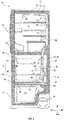
- FIG. 1 illustrates a front view showing a brief structure of the refrigerator 10.
- the refrigerator 10 has a heat insulating cabinet 11 as a main body.
- a storage chamber for storing food etc. is formed in the interior of the heat insulating cabinet 11.
- the topmost layer is a refrigerating chamber 15
- an upper-layer freezing chamber 18 is disposed below the refrigerating camber 15
- a lower-layer freezing chamber 19 is disposed below the upper-layer freezing chamber 18, and the bottommost layer is a vegetable chamber 20.
- both the upper-layer freezing chamber 18 and lower-layer freezing chamber 19 are storage chambers in a freezing temperature range. In the following depictions, sometimes they are collectedly referred to as freezing chamber 17.
- the upper-layer freezing chamber 18 may also be divided in a left portion and a right portion, with one portion being used as an ice-making chamber.
- the heat insulating cabinet 11 is open forward, and a heat insulating door 21 is disposed in an openable and closeable manner at openings corresponding to the storage chambers.
- the refrigerating chamber 15 is divided in two portions in a left-right direction and the two portions are respectively closed by a corresponding heat insulating door 21.
- An upper end and a lower end of the outer side of the heat insulating door 21 in a widthwise direction are rotatably mounted on the heat insulating cabinet 11.
- the heat insulating doors 23, 24, 25 are combined with respective storage chambers, and supported on the heat insulating cabinet 11 in front of the refrigerator 10 in a drawable manner. Specifically, the heat insulating door 23 closes the upper-layer freezing chamber 18, the heat insulating door 24 closes the lower-layer freezing chamber 19, and the heat insulating door 25 closes the vegetable chamber 20.
- FIG. 2 illustrates a side cross-sectional view showing a brief structure of the refrigerator 10.
- the main body, namely, the heat insulating cabinet 11, of the refrigerator 10 comprises a housing 12 opening forward and made of a steel plate, and an liner 13 which is disposed in the housing 12 with a gap with the housing 12, opens forward and is made of a synthetic resin.
- a heat insulating material 14 made of foamed polyurethane is filled in the gap between the housing 12 and the liner 13.
- the heat insulating door 21 and other heat insulating doors also employ the same heat insulating configuration as the heat insulating cabinet 11.
- the refrigerating chamber 15 and the freezing chamber 17 therebelow are partitioned by a heat insulation partition wall 42.
- the upper-layer freezing chamber 18 is communicated with the lower-layer freezing chamber 19 disposed therebelow, and cold air after cooling may refrigerate them simultaneously.
- the freezing chamber 17 and the vegetable chamber 20 are partitioned by the heat insulation partition wall 43.
- a refrigerating chamber air supply passage 29 which is divided by a separator 65 made of a synthetic resin and acts to supply cold air to the refrigerating chamber 15.
- the refrigerating chamber air supply passage 29 is formed with blowing outlets 33 through which cold air flows into the refrigerating chamber 15.
- a freezing chamber air supply passage 31 On the rear side of the freezing chamber 17 is formed a freezing chamber air supply passage 31 which enables cold air cooled by a cooler 45 to flow towards the freezing chamber 17.
- a cooling chamber 26 is formed on the rear side of the freezing chamber air supply passage 31.
- an air evaporator In the interior of the cooling chamber 26 is configured an air evaporator, namely, cooler 45 for cooling air circulating in the cabinet.
- the freezing chamber air supply passage 31 is a space enclosed by a front cover 67 and a separator 66 respectively from front and rear.
- the cooler 45 is connected with a compressor 44, an unshown radiator and an unshown expansion unit, namely, a capillary tube via a refrigerant pipe, to constitute a vapor compression-type freezing loop.
- FIG. 3 is a side cross-sectional view showing a structure nearby a cooling chamber 26 of the refrigerator 10.
- the cooling chamber 26 is located in the interior of the heat insulating cabinet 11 and disposed on the rear side of the freezing chamber air supply passage 31.
- the cooling chamber 26 and the freezing chamber 17 are separated by the separator 66 made of a synthetic resin.
- a space formed by the freezing chamber air supply passage 31 in front of the cooling chamber 26 and located between the cooling chamber 26 and the front cover 67 assembled in front and made of a synthetic resin forms an air passage through which the cold air cooled by the cooler 45 flows to the freezing chamber 17.
- the front cover 67 is formed with openings, namely, blowing outlets 34, through which the cold air is blown to the freezing chamber 17.
- an air return portion 38 allowing air to return from the freezing chamber 17 to the cooling chamber 26. Furthermore, in a lower portion of the cooling chamber 26 is formed an air return port 28 communicated with the air return port 38 and configured to suck the return cold air from the respective storage chambers into the interior of the cooling chamber 26. The cold air returned through an air return port 39 (see FIG. 2 ) of the vegetable chamber 20 and the vegetable chamber return air passage 37 also flows into the air return port 28.
- a defrost heater 46 as a defrosting unit for melting and removing defrost adhered to the cooler 45.
- the defrost heater 46 is a resistance heating heater.
- an air supply port 27 which is an opening connected to each storage chamber.
- the air supply port 27 is an opening through which cold air cooled by the cooler 45 flows, and communicates the cooling chamber 26 with the refrigerating chamber air supply passage 29 and the freezing chamber air supply passage 31.
- a blower fan 47 for sending cold air toward the freezing chamber 17 and the like is arranged at the position of the air supply port 27.
- a shielding apparatus 70 for properly closing the air passage connected from the air supply port 27.
- the shielding apparatus 70 is covered by a front cover 67 from the front.
- an air damper may be installed in the refrigerating chamber air supply passage 29.
- the shielding apparatus 70 and the air damper can be used to properly deliver cold air to each storage chamber.
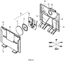
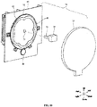
- FIG. 4 illustrates an exploded perspective view of the front cover 67, the shielding apparatus 70 and the separator 66.
- the shielding apparatus 70 is arranged between the front cover 67 and the separator 66.
- the shielding apparatus 70 comprises a cover member 57, a rotatable plate 73 and a support base 63.
- the cover member 57 is a member that closes the rotatable plate 73 from the front, and has a substantially circular shape when viewed from the front.
- the rotatable plate 73 is a substantially disc-shaped member that is rotatable to open and close the shielding apparatus 70, and is mounted rotatable relative to the support base 63.
- the support base 63 is composed of a synthetic resin plate formed in a given shape, and various components constituting the shielding apparatus 70 are mounted on the support base 63.
- the support base 63 is embedded into an opening portion 35 in an upper portion of of the front cover 67. The construction of the shielding apparatus 70 will be described in further detail below with reference to FIG. 6 .
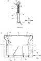
- FIG. 5(A) is a cross-sectional view of the separator 66 and the front cover 67 in which partial structure of the shielding apparatus 70 is embedded.
- a space surrounded by the separator 66 and the front cover 67 is formed as the freezing chamber air supply passage 31.
- the freezing chamber air supply passage 31 is divided into a plurality of air passages.
- the shielding apparatus 70 and a shielding wall drive mechanism 60 are arranged between the separator 66 and the front cover 67.
- the blower fan 47 is disposed in the shielding apparatus 70, and the shielding wall drive mechanism 60 drives the shielding apparatus 70.
- the structure of the shielding apparatus 70 and the shielding wall drive mechanism 60 will be further described with reference to FIG. 6 .
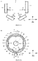
- FIG. 5(B) is a schematic view of the separator 66 viewed from the front.
- the blowing outlet 34 on the separator 66 specifically includes a blowing outlet 341 to a blowing outlet 346.
- the blowing outlet 341 and the blowing outlet 342 are formed at an upper end of the separator 66, the blowing outlet 343 and the blowing outlet 344 are formed at a center of the separator 66 in a vertical direction, and the blowing outlet 345 and blowing outlet 346 are formed at a lower end of the separator 66.
- the separator 66 is formed with a rib-shaped air passage partition wall 56 protruding forward. A front end of the air passage partition wall 56 abuts against the front cover 67.
- the air passage partition wall 56 finely divides the aforementioned freezing chamber air supply passage 31 into a plurality of air passages.
- FIG. 6(A) is an exploded perspective view of the shielding apparatus 70
- FIG. 6(B) is a perspective view of a cam 61.
- the shielding apparatus 70 comprises a rotatable shielding wall 71, the support base 63, the cover member 57 and the shielding wall drive mechanism 60.
- the shielding apparatus 70 is a device that shields the air passage of the cold air blown by the blower fan 47.
- the air passage connecting the cooling chamber 26 with each storage chamber is communicated by making the shielding apparatus 70 in an open state, and the air passage is blocked by making the shielding apparatus 70 in a closed state.
- the blower fan 47 is arranged at the center of a rear surface of the support base 63 via fastening means such as screws.
- the bower fan 47 for example comprise a centrifugal fan such as a turbo fan, and a blower motor that rotates the centrifugal fan to blow air radially outward.
- the rotatable shielding wall 71 is a plate-shaped member made of rectangular synthetic resin, and has a long side along a tangential direction of an outer edge of the rotatable plate 73. A rear side of the rotatable shielding wall 71 is rotatably mounted near a peripheral edge of the support base 63. A plurality of rotatable shielding walls 71 are arranged, specifically, four rotatable shielding walls 71 are arranged. The rotatable shielding wall 71 is arranged on a path through which the cold air blown by the blower fan 47 flows, and properly shields the air passage.
- a frame-shaped portion 83 is adjoined to a rotation center, namely, a base end, of the rotatable shielding wall 71.
- the frame-shaped portion 83 is disposed along the outer periphery of the rotatable shielding wall 71 in an upstanding state.
- the frame-shaped portions each 83 are formed by a frame-shaped synthetic resin, and disposed on a rear surface of the support base 63 in a manner of surrounding the blower fan 71.
- the frame-shaped portions 83 are configured corresponding to the rotatable shielding walls 71, and the air passages will be closed in a way that the rotatable shielding walls 71 close the openings of the frame-shaped portions 83.
- the shielding wall drive mechanism 60 that performs the opening/closing operation of the rotatable shielding wall 71 includes the rotatable plate 73, the cam 61, and a drive motor 74 that rotates the rotatable plate 73.
- the drive motor 74 is not shown.
- the rotatable plate 73 has a substantially disc shape when viewed from the rear, and is rotatably arranged on the front surface side of the support base 63.
- the rotatable plate 73 is formed with a sliding groove 80 for rotating the rotatable shielding wall 71.
- the sliding groove 80 is formed as a bottomed groove surrounded by ribs on the rear surface of the rotatable plate 73. As described later, the rotatable plate 73 is driven to rotate by a drive motor so that the rotatable shielding wall 71 performs the opening/closing operation.
- a gear groove 49 for transmitting the driving force from the motor is formed on the edge of the rotatable plate 73.
- the gear groove 49 is formed at the entire circumference of the rotatable plate 73.
- the cover member 57 is a plate-shaped member that covers the rotatable plate 73 from the front, is formed slightly larger than the rotatable plate 73, and has a substantially circular shape when viewed from the front.
- a position detection device namely, a distance sensor 72 that detects the position of the rotatable plate 73 in the rotation direction.
- the distance sensor 72 will be described later with reference to FIG. 9 .
- the cam 61 is a flat rectangular parallelepiped member made of synthetic resin.
- a rotational connection portion 48 is formed by making a left end of the cam 61 protrude rearward.
- a hole portion for insertion of a pin 69 to be described later is formed at the rotatable connection portion 48.
- a moving shaft 76 protruding in a substantially cylindrical shape is formed from a front surface of a right end side of the cam 61. The moving shaft 76 engages with the sliding groove 80 of the rotatable plate 73, and in use, the moving shaft 76 slides relative to the sliding groove 80.
- the diameter of the moving shaft 76 is set to be the same as the width of the sliding groove 80 in a radial direction or slightly smaller than the width of the sliding groove 80.
- FIG. 7 is an exploded perspective view of the rotatable shielding wall 71, the support base 63 and the cam 61 as viewed from the left rear.
- FIG. 7(B) is an exploded perspective view of a rotational connection portion 68 and the cam 61 as viewed from the left front.
- the rotatable shielding wall 71 is provided with a rotational connection portion 68 obliquely protruding from the base end of the rotatable shielding wall 71.
- the rotational connection portion 68 is formed with a hole through which the pin 69 can be inserted.
- a rotational connection portion 64 protruding in a substantially cylindrical shape is formed at a front end of each of an upper side and a lower side of the rotatable shielding wall 71.
- the rotational connection portion 64 is inserted into a cylindrical recess 85 formed in the inner wall of the frame-shaped portion 83.
- the support base 63 is provided with a rectangular through hole 86.
- the rotational connection portion 68 of the rotatable shielding wall 71 is inserted into the through hole 86 from the rear.
- the rotational connection portion 48 of the cam 61 is inserted into the through hole 86 from the front.
- the pin 69 is inserted into the hole of the rotational connection portion 68 of the rotatable shielding wall 71 and the hole of the rotational connection portion 48 of the cam 61.
- a cam receiving portion 62 is formed on the front surface of the support base 63.
- the cam receiving portion 62 is a rectangular area surrounded by ribs, and the aforementioned through hole 86 is formed in the cam receiving portion 62.
- the cam 61 is received and slides in the cam receiving portion 62.
- a direction in which the cam 61 slides in the cam receiving portion 62 is a left-right direction, in other words, in a radial direction of the rotatable plate 73 shown in FIG. 6(A) .
- the drive motor drives the rotatable plate 73 to rotate
- the moving shaft 76 slides in the sliding groove 80.
- the cam 61 slides in the cam receiving portion 62.
- the rotatable shielding wall 71 can be rotated about the pin 69.
- the cam 61 sliding toward the peripheral edge of the support base 63
- the rotatable shielding wall 71 rotates in an upstanding state with the rotational connection portion 64 as a center of rotation, and the rotatable shielding wall 71 becomes a state orthogonal and perpendicular to a main surface of the support base 63.
- the rotatable shielding wall 71 rotates in a horizontal state with the rotational connection portion 64 as a center of rotation, and the rotatable shielding wall 71 becomes a state substantially parallel to the main surface of the support base 63.
- the rotatable shielding wall 71 can be made in a closed state. Conversely, if the sliding groove 80 is formed near the center of the rotatable plate 73, the rotatable shielding wall 71 can be made in an open state. Using this principle, the open or closed state of the rotatable shielding wall 71 can be arbitrarily set by a meandering design of the shape of the sliding groove 80. Thus, the rotatable shielding wall 71 can be made in a fully open state or a fully closed state without using a complicated structure.
- FIG. 8(A) is a view of the rotatable shielding walls 711 of the shielding apparatus 70 as viewed from the rear.
- the shielding apparatus 70 has a rotatable shielding wall 711 to a rotatable shielding wall 714 which are collectively referred to as the rotatable shielding wall 71.
- the rotatable shielding wall 711 to the rotatable shielding wall 714 have a rectangular shape having long sides that are substantially parallel to the tangential direction of the rotatable plate 73.
- the rotatable shielding wall 711 to the rotatable shielding wall 714 are rotatably mounted on the peripheral edge portion of the support base 63 shown in FIG. 7(A) .
- the base end of the rotatable shielding wall 711 is rotatably connected to the cam 611 formed with the moving shaft 761.
- the base end of the rotatable shielding wall 712 is rotatably connected to the cam 612 formed with the moving shaft 762.
- the base end of the rotatable shielding wall 713 is rotatably connected to the cam 613 formed with the moving shaft 763.
- the base end of the rotatable shielding wall 714 is rotatably connected to the cam 614 formed with the moving shaft 764.
- the rotatable plate 73 is a steel plate or a synthetic resin plate formed into a substantially disc shape, and is formed with the sliding groove 80 for implementing the opening/closing operation of the rotatable shielding wall 711.
- the gear groove 49 is formed in the entire area of the circumference of the rotatable plate 73.
- the gear 30 meshes with the gear groove 49 so that the rotatable plate 73 is rotated based on a torque of the drive motor 74.
- the sliding groove 80 is formed in a substantially annular shape near the outer peripheral edge of the rotatable plate 73. Furthermore, the shape of the sliding groove 80 when the rotatable plate 73 is viewed from the rear is not a perfect circle shape, but a meandering shape curved and extended along the circumferential direction of the rotatable plate 73. Specifically, the sliding groove 80 consists of sliding grooves 801 to 8012 in a clockwise direction. The sliding groove 801 curves radially outward in the clockwise direction. The sliding groove 802 extends substantially parallel to the circumferential direction. The sliding groove 803 curves radially inward in the clockwise direction. The sliding groove 804 curves radially outward in the clockwise direction.
- the sliding groove 805 curves radially inward in the clockwise direction.
- the sliding groove 806 curves radially outward in the clockwise direction.
- the sliding groove 807 curves radially inward in the clockwise direction.
- the sliding groove 808 curves radially outward in the clockwise direction.
- the sliding groove 809 curves radially inward in the clockwise direction.
- the sliding groove 8010 curves radially outward in the clockwise direction.
- the sliding groove 8011 extends substantially parallel to the circumferential direction.
- the sliding groove 8012 curves radially inward in the clockwise direction.
- the sliding groove 80 is provided with change points at which the curved shape of the sliding groove 80 changes. Specifically, a change point 812 is provided between the sliding groove 801 and the sliding groove 802, and a change point 813 is provided between the sliding groove 802 and the sliding groove 803. In addition, a change point 814 is provided between the sliding groove 803 and the sliding groove 804, and a change point 815 is provided between the sliding groove 804 and the sliding groove 805. In addition, a change point 816 is provided between the sliding groove 805 and the sliding groove 806, and a change point 817 is provided between the sliding groove 806 and the sliding groove 807.
- a change point 818 is provided between the sliding groove 807 and the sliding groove 808, and a change point 819 is provided between the sliding groove 808 and the sliding groove 809.
- a change point 8110 is provided between the sliding groove 809 and the sliding groove 8010, and a change point 8111 is provided between the sliding groove 8010 and the sliding groove 8011.
- a change point 8112 is provided between the sliding groove 8011 and the sliding groove 8012, and a change point 811 is provided between the sliding groove 8012 and the sliding groove 801.
- the change point 812, change point 813, change point 815, change point 817, change point 819, change point 8111 and change point 812 are arranged on the radially outer side of the rotatable plate 73.
- the change point 811, the change point 814, the change point 816, the change point 818 and the change point 8110 are arranged on the radially inner side of the rotatable plate 73.
- the rotatable shielding walls 711 to 714 can be set to a given opening/closing mode.
- an angular interval ⁇ at which the change points are separated from one another to 30 degrees, a total of 12 types of opening/closing modes from the rotatable shielding wall 711 to the rotatable shielding wall 714 are achieved, as described later.
- FIG. 9 shows an example in which a distance sensor 72 is used as the position detection device
- FIG. 10 shows an example in which a resistor 52 is used as the position detection device
- FIG. 11 shows an example in which a magnetic sensor 41 is used as the position detection device.
- FIG. 9 there is shown an example in which the distance sensor 72 is used as the position detection device.
- FIG. 9(A) shows the shielding apparatus 70 using the distance sensor 72
- FIG. 9(B) is a cross-sectional view when an annular protrusion 50 shown in FIG. 9(A) is linearly deployed and sectioned.
- the annular protrusion 50 is formed by making a front center portion of the rotatable plate 73 protrude forward in an annular shape.
- the annular protrusion 50 changes in height in the circumferential direction.
- the distance sensor 72 is arranged on the rear surface of the cover member 57 overlapping the annular protrusion 50.
- the distance sensor 72 emits an electromagnetic wave or acoustic wave toward a front portion of the annular protrusion 50 and receives the electromagnetic wave or acoustic wave reflected from the front portion of the annular protrusion 50.
- the distance between the front surface of the annular protrusion 50 and the distance sensor 72 namely, the height of the annular protrusion 50, can be detected as described below.
- the annular protrusion 50 has a start point 501 and an end point 502 that are adjacent to each other, and the protrusion height of the annular protrusion 50 gradually increases from the start point 501 to the end point 502.
- the distance sensor 72 has a transmitting portion 721 and a receiving portion 722.
- the transmitting portion 721 generates the electromagnetic wave or acoustic wave toward an upper surface of the annular protrusion 50.
- the receiving part 722 receives the electromagnetic wave or acoustic wave reflected from the upper surface of the annular protrusion 50.
- a distance from the front surface of the annular protrusion 50 to the distance sensor 72 can be calculated by measuring the time from transmission to reception of the distance sensor 72, that is, the thickness of the annular protrusion 50 can be calculated.
- the start point 501 is the thinnest
- the end point 502 is the thickest.
- the position of the rotatable plate 73 in the rotation direction namely, a rotation angle of the rotatable plate 73 can be detected by measuring the thickness of the annular protrusion 50.
- FIG. 10 is an exploded perspective view of the shielding apparatus 70 using the resistor 52 as the position detecting device.
- the resistor 52 has a rotating shaft 53 rotatably provided. A rear end of the rotating shaft 53 is inserted into an insertion hole 51 formed in the central portion of the rotatable plate 73.
- the insertion hole 51 has a substantially semicircular shape
- the rotating shaft 53 also has a substantially semicircular shape. Therefore, when the rotatable plate 73 rotates, the rotating shaft 53 also rotates simultaneously.
- the resistor 52 is a variable resistor whose resistance value changes with the rotation of the rotating shaft 53. Thus, the position of the rotatable plate 73 in the rotation direction can be detected by measuring the resistance value of the resistor 52.
- the rotation angle of the rotatable plate 73 is detected here based on the resistance value detected by the resistor 52, the rotation angle of the rotatable plate 73 can also be detected based on electrical characteristic values other than the resistance value, such as a current value.
- FIG. 11 is an exploded perspective view of the shielding apparatus 70 using the magnetic sensor 41 as the position detection device.
- a magnet 40 is arranged at the center of the rotatable plate 73.
- the magnet 40 magnetizes an N pole and an S pole in a given pattern in the circumferential direction.
- the magnet 40 rotates together with the rotatable plate 73.
- a magnetic sensor 41 is arranged on the rear of the cover member 57 and at a position overlapping or in the vicinity of the magnet 40 as viewed from the front.
- the magnetic sensor 41 detects the position of the magnet 40 in the rotation direction by detecting the magnetic field generated from the magnet 40.
- the magnet 40 In an in-use state of the shielding apparatus 70, if the rotatable plate 73 rotates, the magnet 40 also rotates together. As the magnet 40 rotates, the magnetic field generated from the magnet 40 changes. The position of the rotatable plate 73 in the rotation direction can be detected by detecting the change in the magnetic field by the magnetic sensor 41.
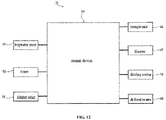
- the connection structure of the refrigerator 10 will be described with reference to the block diagram of FIG. 12 .
- the refrigerator 10 has a control device 54, a temperature sensor 91, a timer 92, a distance sensor 72, a compressor 44, a blower fan 47, a drive motor 74 and a defrost heater 46.
- the temperature sensor 91, the timer 92 and the distance sensor 72 are connected to an input side terminal of the control device 54.
- the compressor 44, the blower fan 47, the drive motor 74 and the defrost heater 46 are connected to an output side terminal of the control device 54.
- the control device 54 is for example a CPU and controls the compressor 44 based on input information from the temperature sensor 91, thereby controlling the cooling operation of the refrigerator 10.
- the control device 54 controls the shielding wall drive mechanism 60 based on the input information from the distance sensor 72 to control the opening and closing of the rotatable shielding wall 71.
- the temperature sensor 91 is disposed in the refrigerating chamber 15, the freezing chamber 17 and the vegetable chamber 20, respectively, and transmits information indicating the temperature in the storage chambers to the control device 54.
- the timer 92 measures a cooling time for cooling the refrigerating chamber 15, the freezing chamber 17 and the vegetable chamber 20, and an operation time of the defrost heater 46, and transmits information indicating the respective time to the control device 54.
- the distance sensor 72 detects the position, namely, a rotation angle, of the rotatable plate 73 in the rotation direction by measuring the distance from the annular protrusion 50 of the rotatable plate 73.
- the resistor 52 shown in FIG. 10 and the magnetic sensor 41 shown in FIG. 11 may be used.
- the compressor 44 by following an instruction from the control device 54, compresses the refrigerant used in the refrigeration loop.
- the blower fan 47 by following the instruction from the control device 54, blows the cold air cooled by the cooler 45 of the refrigeration loop toward each storage chamber.
- the drive motor 74 by following the instruction from the control device 54 , drives the rotatable plate 73 of the shielding apparatus 70 to rotate by a given angle.
- a stepping motor may be used as the drive motor 74, for example.
- the defrost heater 46 is energized in accordance with the instruction from the control device 54 to heat the air in the cooling chamber 26.
- FIG. 13 through FIG. 18 illustrate that the rotatable plate 73 of the shielding apparatus 70 is made rotate in units of 30 degrees so that the rotatable shielding walls 711 to 714 are opened or closed to open or close the air passages and perform a switching action.
- the radial direction and the circumferential direction of the rotatable plate 73 are referred to as the radial direction and the circumferential direction.
- the open or closed state of the rotatable shielding wall 711 and the like is switched from mode 1 to mode 12 by rotating the rotatable plate 73 clockwise in units of 30 degrees.
- the opening/closing of the rotatable shielding walls 711 to 714 is controlled by setting an allocated angle of the rotatable plate 73 to 30 degrees and by rotating the rotatable plate 73 in units of 30 degrees.
- the allocated angle is set to a divisor of 360 degrees, for example, 60 degrees or 120 degrees may be used.
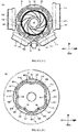
- Mode 1 is shown in FIG. 13 and FIG. 14
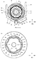
- Mode 6 is shown in FIG. 15 and FIG. 16
- Mode 12 is shown in FIG. 17 and FIG. 18 .
- FIG. 13 and FIG. 14 show Mode 1 in which all the rotatable shielding walls 71 are made in an open state.
- FIG. 13(A) is a view of the shielding apparatus 70 in this state as viewed from the rear
- FIG. 13(B) is a view of the rotatable plate 73 in this state as viewed from the rear
- FIG. 14 is a view of the air passage in this state as viewed from the rear.
- the rotatable shielding wall 711 to the rotatable shielding wall 714 are all in an open state.
- the blower fan 47 can be used to send the cold air to the refrigerating chamber 15 and the freezing chamber 17 by setting the open state.
- the moving shafts such as the moving shaft 761 are disposed radially inside.
- the moving shaft 761 is disposed at the change point 814 of the sliding groove 80
- the moving shaft 762 is disposed at the change point 816 of the sliding groove 80
- the moving shaft 763 is disposed at the change point 818 of the sliding groove 80
- the moving shaft 764 is disposed at the change point 8110 of the sliding groove 80.
- the state in which the rotatable plate 73 is in Mode 1 can be detected by the control device 54 based on the output of the distance sensor 72 shown in FIG. 9 .
- the states of Mode 6 and Mode 12 described later can also be detected.
- the control device 54 controls the drive motor 74 to operate to rotate the rotatable plate 73 via the gear 30.
- the control device 54 measures the rotation angle of the rotatable plate 73 through the distance sensor 72, and accurately controls the rotation position of the rotatable plate 73.
- the rotatable plate 73 is rotated clockwise by 150 degrees as indicated by the solid line arrow.
- the rotatable plate 73 is rotated counterclockwise by 210 degrees as indicated by the dashed line arrow.
- the gear groove 49 is formed on the entire circumference of the outer edge of the rotatable plate 73, and the rotation angle of the rotatable plate 73 is detected by the distance sensor 72. Accordingly, when the rotatable plate 73 is rotated to change the opening/closing mode of the rotatable shielding wall 71, the rotatable plate 73 can be accurately rotated in both the clockwise rotation and the counterclockwise rotation.
- FIG. 15 and FIG. 16 show Mode 6 in which only the rotatable shielding wall 712 disposed at the lower right side is set to the open state.
- FIG. 15(A) is a view of the shielding apparatus 70 in this state as viewed from the rear
- FIG. 15(B) is a view of the rotatable plate 73 in this state as viewed from the rear
- FIG. 16 is a view of the air passage in this state as viewed from the rear.
- the rotatable shielding wall 711, the rotatable shielding wall 713 and the rotatable shielding wall 714 are set to the closed state, and only the rotatable shielding wall 712 is set to the open state.
- the blower fan 47 can send cold air to the lower right portion of the freezing chamber 17.
- the moving shaft 761, the moving shaft 763 and the moving shaft 764 are arranged radially outside, and the moving shaft 762 is arranged radially inside.
- the moving shaft 761 is arranged at the change point 8111 of the sliding groove 80
- the moving shaft 762 is arranged at the change point 811 of the sliding groove 80.
- the moving shaft 763 is arranged at the change point 813 of the sliding groove 80
- the moving shaft 764 is arranged at the change point 815 of the sliding groove 80.
- the rotatable shielding wall 711, the rotatable shielding wall 713 and the rotatable shielding wall 714 shield the cold air, and on the other hand, the rotatable shielding wall 712 does not shield the cold air. Therefore, cold air is blown toward the lower right side. Specifically, after being sent towards the blowing outlet 344 and the blowing outlet 346, the cold air is blown out through the outlets to the freezing chamber 17.
- the rotatable plate 73 when the mode is transitioned from Mode 6 shown in FIG. 15 to Mode 12 shown in FIG. 17 , the rotatable plate 73 is rotated counterclockwise by 180 degrees as indicated by the solid line arrow. Alternatively, the rotatable plate 73 is rotated clockwise by 180 degrees as indicated by the dashed line arrow.
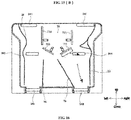
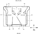
- FIG. 17 and FIG. 18 show Mode 12 in which all the rotatable shielding walls such as rotatable shielding wall 714 are set to the closed state.
- FIG. 17(A) is a view of the shielding apparatus 70 in this state as viewed from the rear
- FIG. 17(B) is a view of the rotatable plate 73 in this state as viewed from the rear
- FIG. 18 is a view of the air passage in this state as viewed from the rear.
- the rotatable shielding wall 711, the rotatable shielding wall 712, the rotatable shielding wall 713 and the rotatable shielding wall 714 are set in the closed state.
- the closed state With the closed state being set, the air supply path from the blower fan 47 is closed, so that the cooling chamber 26 and the freezing chamber 17 shown in FIG. 3 are in an isolated state.
- the moving shaft 761, the moving shaft 762, the moving shaft 763 and the moving shaft 764 are arranged radially outside.
- the moving shaft 761 is arranged at the change point 815 of the sliding groove 80
- the moving shaft 762 is arranged at the change point 817 of the sliding groove 80
- the moving shaft 763 is arranged at the change point 819 of the sliding groove 80
- the moving shaft 764 is arranged at the change point 8111 of the sliding groove 80.
- the rotatable shielding wall 711, the rotatable shielding wall 712, the rotatable shielding wall 713 and the rotatable shielding wall 714 are in the closed state.
- the rotatable shielding wall 711, the rotatable shielding wall 712, the rotatable shielding wall 713 and the rotatable shielding wall 714 shield cold air. Therefore, the cold air is not sent to the blowing outlets such as the blowing outlet 342.
- the rotatable plate 73 when the mode is transitioned from Mode 12 shown in FIG. 17 to Mode 1 shown in FIG. 13 , the rotatable plate 73 is rotated counterclockwise by 330 degrees as indicated by the solid lie arrow. Alternatively, the rotatable plate 73 is rotated clockwise by 30 degrees as indicated by the dashed line arrow.
- the control device 54 controls the rotatable plate 73 to rotate in a direction with a less stroke, i.e., rotate in a clockwise rotation direction indicated by a dashed line, based on the position detection of the rotatable plate 73. In this way, the action amount and action time of the shielding apparatus 70 when the open/closing mode is altered can be reduced.
- the opening/closing action of the rotatable shielding wall 71 is performed by the rotation of the rotatable plate 73. Therefore, the shielding apparatus 70 can be made thinner as compared with the technique described in the above BACKGROUND. Therefore, referring to FIG. 2 , the volume of the freezer chamber 17 in front of the shielding apparatus 70 is increased.
- the sliding groove 80 is substantially provided in an annular shape, and the moving shafts 761 to 764 engage with the sliding groove 80. Then, the rotatable plate 73 is rotated so that the moving shafts 761 to 764 slide in the sliding groove 80 and slide in the radial direction of the rotatable plate 73.
- the cams 611 to 614 also slide. As a result, the rotatable shielding walls 711 to 714 are opened and closed.
- the plurality of moving shafts 761 to 764 engage with one sliding groove 80 to slide, so the sliding distance of the moving shafts 761 to 764 in the sliding groove 80 can be increased. Therefore, the sliding groove 80 can be bent smoothly in the circumferential direction, a pressure generated by the moving shafts 761 to 764 upon sliding in the sliding groove 80 is reduced, and the opening/closing action of the rotatable shielding wall 711 can be performed smoothly.
- the opening/closing mode of the rotatable shielding walls 711 to 714 can be achieved in various manners by simple control of rotating the shielding apparatus 70 by a given angle.
- 12 types of open/closed modes can be achieved in units of 30 degrees. Therefore, it is possible to realize multiple cold air supply manners and properly supply cold air according to cooling conditions in the interior of the freezing chamber 17.
- the shielding apparatus 70 can rotate the rotatable plate 73. In this way, the open/closed mode of the rotatable shielding walls 711 to 714 can be accurately controlled.
- the gear groove 49 is formed in the entire area of the outer edge of the rotatable plate 73.
- the rotatable plate 73 can be rotated in both the clockwise direction and the counterclockwise direction to alter the open/closed mode of the rotatable shielding walls 711 to 714.
- the time and action amount for altering the open/closed mode can be reduced by selecting one rotation manner with a small rotation angle from the clockwise rotation and the counterclockwise rotation.
Landscapes
- Engineering & Computer Science (AREA)
- Mechanical Engineering (AREA)
- General Engineering & Computer Science (AREA)
- Chemical & Material Sciences (AREA)
- Combustion & Propulsion (AREA)
- Physics & Mathematics (AREA)
- Thermal Sciences (AREA)
- Cold Air Circulating Systems And Constructional Details In Refrigerators (AREA)
Abstract
Description
- The present invention relates to a shielding apparatus and a refrigerator having the same, and in particular to a shielding apparatus for properly closing an air passage which communicates a cooling chamber with a storage chamber, and a refrigerator having such a shielding apparatus.
- Patent document 1 (
JP Patent Publication No. 2013-2664 -
FIG. 19 illustrates arefrigerator 100 disclosed in the document. In therefrigerator 100 shown inFIG. 19 are formed a refrigeratingchamber 101, afreezing chamber 102 and avegetable chamber 103. Acooling chamber 104 receiving acooler 108 is formed on a rear side of thefreezing chamber 102. A partitioningwall 105 partitioning thecooling chamber 104 from thefreezing chamber 102 is provided with anopening portion 106 through which cold air is supplied to respective storage chambers. In addition, at theopening portion 106 is provided ablower fan 107 that makes cold air flow. Ablower cover 110 covering theblower fan 107 is disposed on the side of thefreezing chamber 102. Anair damper 114 is disposed midway anair passage 109 through which the cold air supplied to the refrigeratingchamber 101 circulates. - Referring to
FIG. 20 , theblower cover 110 is described in detail. At theblower cover 110 is formed a substantiallyquadrangular recess 111, and an upper portion of therecess 111 is cut away to from the opening portion 113. Here, in the case where theblower cover 110 covers theblower fan 107, the opening portion 113 of theblower cover 110 is communicated with theair passage 109 on the side of the main body of the refrigerator. - The
refrigerator 100 with the above structure operates in the following manner. First, in the case where the refrigeratingchamber 101 and thefreezing chamber 102 are cooled simultaneously, theblower cover 110 is made leave theblower fan 107 to open theair damper 114. In this state, theblower fan 107 is made rotate. As such, in the interior of thecooling chamber 104, a portion of cold air cooled by the cooler 108 is sent by an air-blowing force of theblower fan 107 to thefreezing chamber 102. In addition, another portion of the cold air is sent via theair passage 109, theair damper 114 and theair passage 109 to the refrigeratingchamber 101. Hence, both thefreezing chamber 102 and refrigeratingchamber 101 are cooled. - On the other hand, when only the
refrigerating chamber 101 is cooled, theblower cover 110 covers theblower fan 107 and theair damper 114 is opened. In this state, theblower fan 107 is used to send the cold air cooled by the cooler 108. When theblower cover 110 is a closed state, the opening portion 113 formed at the upper portion of theblower cover 110 is made communicate with theair passage 109. Hence, the cold air sent by theblower fan 107 is supplied via the opening portion 113, theair damper 114 and theair passage 109 to therefrigerator chamber 101. - As stated above, with the
blower cover 110 formed with the opening portion 113 being used, onecooler 108 is used to cool a plurality of storage chambers at a proper time. - However, the
blower cover 110 needs a space for making an opening/closing action in a front-rear direction. Hence, to enable theblower cover 110 to make the opening/closing action, a larger space is needed in the interior of therefrigerator 100. As a result, an interior volume of thefreezing chamber 102 formed in front of theblower cover 110 is pressed, and the space of thefreezing chamber 102 for receiving the stored items is limited. Furthermore, a drive sound is generated when a motor is used to drive theblower cover 110 to move in the front-rear direction; when the drive sound is large, the user will feel uncomfortable. - An object of the present invention is to provide a shielding apparatus which does not occupy the in-cabinet volume and can accurately control the rotation of rotatable shielding walls, and a refrigerator having the shielding apparatus.
- To achieve the above object, the present invention provides a shielding apparatus for properly closing an air passage for cold air transmission inside of a refrigerator, the shielding apparatus comprising a plurality of rotatable shielding walls that surround a blower fan from outside in a radial direction; a shielding wall drive mechanism for driving the rotatable shielding walls; a position detection device for detecting a position of the rotatable plate in a rotation direction; and a control device for controlling the shielding wall drive mechanism to operate, the control device controlling the shielding wall drive mechanism to operate according to a detection result of the positon detection device. The shielding wall drive mechanism has a rotatable plate formed with an annular sliding groove; a cam formed with a moving shaft engaging with the sliding groove and the cam rotatably connected with the rotatable shielding wall; and a motor for driving the rotatable plate to rotate. Therefore, the control device controls the shielding wall drive mechanism based on the detection result of the position detection device regarding the position of the rotatable plate in the rotation direction, accurately controls the rotation of the rotatable shielding walls, and achieves accurate control of the opening/closing of the air passage in the refrigerator. Furthermore, whatever position of the rotatable plate, an initial position of the rotatable plate can be detected according to the output of the position detection device without need to provide an abutting portion for detecting the initial position. The sliding groove is provided in an annular shape, which simplifies the overall configuration of the device and avoids occurrence of a problem of noise generated accompanying the abutting action.
- Optionally, wherein the position detection device detects a thickness of the rotatable plate that changes in the rotation direction.
- Optionally, wherein the position detection device detects an electrical characteristic value that changes along with the rotation of the rotatable plate.
- Optionally, wherein the position detection device detects a magnetic field that changes along with the rotation of the rotatable plate.
- Optionally, wherein a gear groove is disposed on an entirety of a circumferential edge of the rotatable plate.
- The present invention further provides a refrigerator, comprising: a freezing loop having a cooler for cooling air supplied to a storage chamber through the air passage; a cooling chamber provided with the cooler and formed with an air supply port connected to the storage chamber; a blower fan configured to supply air supplied through the air supply port towards the storage chamber; and the above-described shielding apparatus for closing at least part of the air passage. The refrigerator of the present invention employs a thin-type shielding apparatus having a plurality of rotatable shielding walls that surround the blower fan from the outside in the radial direction, thereby reducing the occupied area and increasing the volume in the storage chamber. Furthermore, the refrigerator can accurately control the rotation of the rotatable shielding walls according to detection result of the position of the rotatable plate, and accurately control the opening/closing of the air passage in the refrigerator.
-
-
FIG. 1 is a front view showing the appearance of a refrigerator according to an embodiment of the present invention. -
FIG. 2 is a side cross-sectional view showing the internal structure of the refrigerator according to an embodiment of the present invention. -
FIG. 3 is an enlarged side cross-sectional view showing the structure nearby a cooling chamber of the refrigerator according to an embodiment of the present invention. -
FIG. 4 is an exploded perspective view showing a shielding apparatus according to an embodiment of the present invention. -
FIG. 5(A) is a cross-sectional view of the shielding apparatus according to an embodiment of the present invention;FIG. 5(B) is a front view showing a separator. -
FIG. 6(A) is an exploded perspective view of the shielding apparatus according to an embodiment of the present invention;FIG. 6(B) is a perspective view showing a cam of the shielding apparatus. -
FIG. 7(A) is a partially exploded schematic view of the shielding apparatus according to an embodiment of the present invention;FIG. 7(B) is an exploded schematic view of a cam-receiving structure of the shielding apparatus. -
FIG. 8(A) is a view of the shielding apparatus according to an embodiment of the present invention with rotatable shielding walls being viewed from the rear;FIG. 8(B) is a view of the shielding apparatus with a rotatable plate being viewed from the rear. -
FIG. 9(A) shows an exploded perspective view when the shielding apparatus according to the embodiment of the present invention adopts a distance sensor as a position detection device;FIG. 9(B) shows a cross-sectional view when the distance sensor detects an angle of the rotatable plate. -
FIG. 10 is a perspective view when a resistor is used as a position detection device in the shielding apparatus according to an embodiment of the present invention. -
FIG. 11 is a perspective view when a magnetic sensor is used as a position detection device in the shielding apparatus according to an embodiment of the present invention. -
FIG. 12 is a block diagram of the refrigerator according to an embodiment of the present invention. -
FIG. 13(A) is a view showing a state in which the shielding apparatus according to an embodiment of the present invention is viewed from the rear inMode 1;FIG. 13(B) is a view of the rotatable plate inMode 1. -
FIG. 14 is a view showing conditions of an air passage when the shielding apparatus according to an embodiment of the present invention is viewed from the rear inMode 1. -
FIG. 15(A) is a view showing a state in which the shielding apparatus according to an embodiment of the present invention is viewed from the rear in Mode 6;FIG. 15(B) is a view of the rotatable plate in Mode 6. -
FIG. 16 is a view showing conditions of the air passage when the shielding apparatus according to an embodiment of the present invention is viewed from the rear in Mode 6. -
FIG. 17(A) is a view showing a state in which the shielding apparatus according to an embodiment of the present invention is viewed from the rear inMode 12;FIG. 17(B) is a view of the rotatable plate inMode 12. -
FIG. 18 is a view showing conditions of the air passage when the shielding apparatus according to an embodiment of the present invention is viewed from the rear inMode 12. -
FIG. 19 is an enlarged side view of a refrigerator stated in -
FIG. 20 is a perspective view of a blower cover used in the refrigerator stated in BACKGROUND. - 10-refrigerator; 11-heat insulating cabinet; 12-housing; 13-liner; 14-heat insulating material; 15-refrigerating chamber; 17-freezing chamber; 18-upper freezing chamber; 19-lower freezing chamber; 20- vegetable chamber; 21, 23, 24, 25-heat insulating door; 26- cooling chamber; 27- air supply port; 28, 38, 39- air return port; 29- refrigerating chamber air supply passage; 30-gear; 31- freezing chamber air supply passage; 33, 34, 341, 342, 343, 344, 345, 346-blowing outlet; 35-opening portion; 37-vegetable chamber return air passage; 40-magnet; 41-magnetic sensor; 42, 43-heat insulation partition wall; 44-compressor; 45-cooler; 46-defrost heater; 47-blower; 48-rotatational connection portion; 49-gear groove; 50-annular protrusion; 501-start point; 502-end point; 51-insertion hole; 52-resistor; 53-rotating shaft; 54-control device; 56-air passage partition wall; 57-cover member; 60-shielding wall drive mechanism; 61,611,612,613,614-cam 62-cam-receiving portion; 63-support base; 64, 68- rotatable connection portion; 65, 66-separator; 67-front cover; 69-pin; 70-shielding apparatus; 71, 711, 712, 713, 714-rotatable shielding wall; 72-distance sensor; 721-transmitting portion; 722-receiving portion; 73-rotatable plate; 74-driving motor; 76, 761, 762, 763, 764-moving shaft; 80-sliding groove; 801 , 802, 803, 804, 805, 806, 807, 808, 809, 8010, 8011, 8012-sliding groove; 811, 812, 813, 814, 815, 816, 817, 818, 819, 8110, 8111, 8122-change points; 83-frame-shaped portion; 85-recess; 86-through hole; 91-temperature sensor; 92-timer; 100-refrigerator; 101-refrigerating chamber; 102-freezing chamber; 103-vegetable chamber; 104-cooling chamber; 105-partition wall; 106-opening portion; 107-blower fan; 108-cooler; 109-air passage; 110-blower cover; 111-recess; 113-opening portion; 114-air damper.
- The figures are only for illustrative purposes and cannot be construed as limiting the present invention; in order to better illustrate the embodiments, some parts in the figures may be omitted, enlarged or reduced, and do not represent the size of the actual product; It may be appreciated by those skilled in the art that some well-known structures and their descriptions in the figures may be omitted.
- Hereinafter, a shielding
apparatus 70 and arefrigerator 10 according to embodiments of the present invention will be described in detail with reference to figures. In the following depictions, the same parts are designated by the same reference numbers in principle, and repeated depictions will be omitted. Furthermore, in the following depictions, directional terms such as up, down, front, rear, left and right are used properly, but left and right means left and right in a case where therefrigerator 10 is viewed from the rear. Furthermore, in the following depictions, the rotation directions are represented as clockwise and counter-clockwise rotation directions, and these rotation directions indicate directions in the case where therefrigerator 10 is viewed from the rear. -
FIG. 1 illustrates a front view showing a brief structure of therefrigerator 10. As shown inFIG. 1 , therefrigerator 10 has aheat insulating cabinet 11 as a main body. A storage chamber for storing food etc. is formed in the interior of theheat insulating cabinet 11. Regarding the storage chamber, the topmost layer is a refrigeratingchamber 15, an upper-layer freezing chamber 18 is disposed below the refrigeratingcamber 15, a lower-layer freezing chamber 19 is disposed below the upper-layer freezing chamber 18, and the bottommost layer is avegetable chamber 20. In addition, both the upper-layer freezing chamber 18 and lower-layer freezing chamber 19 are storage chambers in a freezing temperature range. In the following depictions, sometimes they are collectedly referred to as freezingchamber 17. Here, the upper-layer freezing chamber 18 may also be divided in a left portion and a right portion, with one portion being used as an ice-making chamber. - The
heat insulating cabinet 11 is open forward, and aheat insulating door 21 is disposed in an openable and closeable manner at openings corresponding to the storage chambers. The refrigeratingchamber 15 is divided in two portions in a left-right direction and the two portions are respectively closed by a correspondingheat insulating door 21. An upper end and a lower end of the outer side of theheat insulating door 21 in a widthwise direction are rotatably mounted on theheat insulating cabinet 11. In addition, theheat insulating doors heat insulating cabinet 11 in front of therefrigerator 10 in a drawable manner. Specifically, theheat insulating door 23 closes the upper-layer freezing chamber 18, theheat insulating door 24 closes the lower-layer freezing chamber 19, and theheat insulating door 25 closes thevegetable chamber 20. -
FIG. 2 illustrates a side cross-sectional view showing a brief structure of therefrigerator 10. The main body, namely, theheat insulating cabinet 11, of therefrigerator 10 comprises ahousing 12 opening forward and made of a steel plate, and anliner 13 which is disposed in thehousing 12 with a gap with thehousing 12, opens forward and is made of a synthetic resin. Aheat insulating material 14 made of foamed polyurethane is filled in the gap between thehousing 12 and theliner 13. In addition, theheat insulating door 21 and other heat insulating doors also employ the same heat insulating configuration as theheat insulating cabinet 11. - The refrigerating
chamber 15 and the freezingchamber 17 therebelow are partitioned by a heatinsulation partition wall 42. In addition, the upper-layer freezing chamber 18 is communicated with the lower-layer freezing chamber 19 disposed therebelow, and cold air after cooling may refrigerate them simultaneously. Furthermore, the freezingchamber 17 and thevegetable chamber 20 are partitioned by the heatinsulation partition wall 43. - On the back side of the refrigerating
chamber 15 is formed a refrigerating chamberair supply passage 29 which is divided by aseparator 65 made of a synthetic resin and acts to supply cold air to the refrigeratingchamber 15. The refrigerating chamberair supply passage 29 is formed with blowingoutlets 33 through which cold air flows into the refrigeratingchamber 15. - On the rear side of the freezing
chamber 17 is formed a freezing chamberair supply passage 31 which enables cold air cooled by a cooler 45 to flow towards the freezingchamber 17. A cooling chamber 26 is formed on the rear side of the freezing chamberair supply passage 31. In the interior of the cooling chamber 26 is configured an air evaporator, namely, cooler 45 for cooling air circulating in the cabinet. The freezing chamberair supply passage 31 is a space enclosed by afront cover 67 and aseparator 66 respectively from front and rear. - The cooler 45 is connected with a
compressor 44, an unshown radiator and an unshown expansion unit, namely, a capillary tube via a refrigerant pipe, to constitute a vapor compression-type freezing loop. -
FIG. 3 is a side cross-sectional view showing a structure nearby a cooling chamber 26 of therefrigerator 10. The cooling chamber 26 is located in the interior of theheat insulating cabinet 11 and disposed on the rear side of the freezing chamberair supply passage 31. The cooling chamber 26 and the freezingchamber 17 are separated by theseparator 66 made of a synthetic resin. - A space formed by the freezing chamber
air supply passage 31 in front of the cooling chamber 26 and located between the cooling chamber 26 and thefront cover 67 assembled in front and made of a synthetic resin forms an air passage through which the cold air cooled by the cooler 45 flows to the freezingchamber 17. Thefront cover 67 is formed with openings, namely, blowingoutlets 34, through which the cold air is blown to the freezingchamber 17. - On the back side of the lower portion of the lower-
layer freezing chamber 19 is formed anair return portion 38 allowing air to return from the freezingchamber 17 to the cooling chamber 26. Furthermore, in a lower portion of the cooling chamber 26 is formed anair return port 28 communicated with theair return port 38 and configured to suck the return cold air from the respective storage chambers into the interior of the cooling chamber 26. The cold air returned through an air return port 39 (seeFIG. 2 ) of thevegetable chamber 20 and the vegetable chamberreturn air passage 37 also flows into theair return port 28. - In addition, below the cooler 45 is disposed a
defrost heater 46 as a defrosting unit for melting and removing defrost adhered to the cooler 45. Thedefrost heater 46 is a resistance heating heater. - In the upper portion of the cooling chamber 26, there is formed an
air supply port 27 which is an opening connected to each storage chamber. Theair supply port 27 is an opening through which cold air cooled by the cooler 45 flows, and communicates the cooling chamber 26 with the refrigerating chamberair supply passage 29 and the freezing chamberair supply passage 31. A blower fan 47 for sending cold air toward the freezingchamber 17 and the like is arranged at the position of theair supply port 27. - On the outside of the
air supply port 27 of the cooling chamber 26 is disposed ashielding apparatus 70 for properly closing the air passage connected from theair supply port 27. The shieldingapparatus 70 is covered by afront cover 67 from the front. - Here, although not shown in
FIG. 3 , an air damper may be installed in the refrigerating chamberair supply passage 29. Through such an arrangement, the shieldingapparatus 70 and the air damper can be used to properly deliver cold air to each storage chamber. -
FIG. 4 illustrates an exploded perspective view of thefront cover 67, the shieldingapparatus 70 and theseparator 66. The shieldingapparatus 70 is arranged between thefront cover 67 and theseparator 66. - The shielding
apparatus 70 comprises a cover member 57, arotatable plate 73 and asupport base 63. The cover member 57 is a member that closes therotatable plate 73 from the front, and has a substantially circular shape when viewed from the front. Therotatable plate 73 is a substantially disc-shaped member that is rotatable to open and close the shieldingapparatus 70, and is mounted rotatable relative to thesupport base 63. Thesupport base 63 is composed of a synthetic resin plate formed in a given shape, and various components constituting the shieldingapparatus 70 are mounted on thesupport base 63. In addition, thesupport base 63 is embedded into an opening portion 35 in an upper portion of of thefront cover 67. The construction of the shieldingapparatus 70 will be described in further detail below with reference toFIG. 6 . -
FIG. 5(A) is a cross-sectional view of theseparator 66 and thefront cover 67 in which partial structure of the shieldingapparatus 70 is embedded. As described above, a space surrounded by theseparator 66 and thefront cover 67 is formed as the freezing chamberair supply passage 31. The freezing chamberair supply passage 31 is divided into a plurality of air passages. In addition, the shieldingapparatus 70 and a shieldingwall drive mechanism 60 are arranged between theseparator 66 and thefront cover 67. The blower fan 47 is disposed in theshielding apparatus 70, and the shieldingwall drive mechanism 60 drives the shieldingapparatus 70. The structure of the shieldingapparatus 70 and the shieldingwall drive mechanism 60 will be further described with reference toFIG. 6 . -
FIG. 5(B) is a schematic view of theseparator 66 viewed from the front. The blowingoutlet 34 on theseparator 66 specifically includes ablowing outlet 341 to ablowing outlet 346. The blowingoutlet 341 and theblowing outlet 342 are formed at an upper end of theseparator 66, the blowingoutlet 343 and theblowing outlet 344 are formed at a center of theseparator 66 in a vertical direction, and theblowing outlet 345 and blowingoutlet 346 are formed at a lower end of theseparator 66. - In addition, the
separator 66 is formed with a rib-shaped airpassage partition wall 56 protruding forward. A front end of the airpassage partition wall 56 abuts against thefront cover 67. The airpassage partition wall 56 finely divides the aforementioned freezing chamberair supply passage 31 into a plurality of air passages. - Referring to
FIG. 6 , the structure of the shieldingapparatus 70 will be described.FIG. 6(A) is an exploded perspective view of the shieldingapparatus 70, andFIG. 6(B) is a perspective view of a cam 61. - Referring to
FIG. 6(A) , the shieldingapparatus 70 comprises arotatable shielding wall 71, thesupport base 63, the cover member 57 and the shieldingwall drive mechanism 60. - The shielding
apparatus 70 is a device that shields the air passage of the cold air blown by the blower fan 47. The air passage connecting the cooling chamber 26 with each storage chamber is communicated by making the shieldingapparatus 70 in an open state, and the air passage is blocked by making the shieldingapparatus 70 in a closed state. - The blower fan 47 is arranged at the center of a rear surface of the
support base 63 via fastening means such as screws. The bower fan 47 for example comprise a centrifugal fan such as a turbo fan, and a blower motor that rotates the centrifugal fan to blow air radially outward. - The
rotatable shielding wall 71 is a plate-shaped member made of rectangular synthetic resin, and has a long side along a tangential direction of an outer edge of therotatable plate 73. A rear side of therotatable shielding wall 71 is rotatably mounted near a peripheral edge of thesupport base 63. A plurality ofrotatable shielding walls 71 are arranged, specifically, fourrotatable shielding walls 71 are arranged. Therotatable shielding wall 71 is arranged on a path through which the cold air blown by the blower fan 47 flows, and properly shields the air passage. - A frame-shaped portion 83 is adjoined to a rotation center, namely, a base end, of the
rotatable shielding wall 71. The frame-shaped portion 83 is disposed along the outer periphery of therotatable shielding wall 71 in an upstanding state. The frame-shaped portions each 83 are formed by a frame-shaped synthetic resin, and disposed on a rear surface of thesupport base 63 in a manner of surrounding theblower fan 71. The frame-shaped portions 83 are configured corresponding to therotatable shielding walls 71, and the air passages will be closed in a way that therotatable shielding walls 71 close the openings of the frame-shaped portions 83. - The shielding
wall drive mechanism 60 that performs the opening/closing operation of therotatable shielding wall 71 includes therotatable plate 73, the cam 61, and adrive motor 74 that rotates therotatable plate 73. Here, thedrive motor 74 is not shown. - The
rotatable plate 73 has a substantially disc shape when viewed from the rear, and is rotatably arranged on the front surface side of thesupport base 63. Therotatable plate 73 is formed with a slidinggroove 80 for rotating therotatable shielding wall 71. The slidinggroove 80 is formed as a bottomed groove surrounded by ribs on the rear surface of therotatable plate 73. As described later, therotatable plate 73 is driven to rotate by a drive motor so that therotatable shielding wall 71 performs the opening/closing operation. - A
gear groove 49 for transmitting the driving force from the motor is formed on the edge of therotatable plate 73. In the present embodiment, thegear groove 49 is formed at the entire circumference of therotatable plate 73. - The cover member 57 is a plate-shaped member that covers the
rotatable plate 73 from the front, is formed slightly larger than therotatable plate 73, and has a substantially circular shape when viewed from the front. - In the cover member 57 is arranged a position detection device, namely, a
distance sensor 72 that detects the position of therotatable plate 73 in the rotation direction. Thedistance sensor 72 will be described later with reference toFIG. 9 . - Referring to
FIG. 6(B) , the cam 61 is a flat rectangular parallelepiped member made of synthetic resin. A rotational connection portion 48 is formed by making a left end of the cam 61 protrude rearward. A hole portion for insertion of a pin 69 to be described later is formed at the rotatable connection portion 48. In addition, a moving shaft 76 protruding in a substantially cylindrical shape is formed from a front surface of a right end side of the cam 61. The moving shaft 76 engages with the slidinggroove 80 of therotatable plate 73, and in use, the moving shaft 76 slides relative to the slidinggroove 80. To enable the sliding, the diameter of the moving shaft 76 is set to be the same as the width of the slidinggroove 80 in a radial direction or slightly smaller than the width of the slidinggroove 80. - Reference is made to
FIG. 7 to describe the relevant structures of therotatable shielding wall 71, thesupport base 63 and the cam 61.FIG. 7(A) is an exploded perspective view of therotatable shielding wall 71, thesupport base 63 and the cam 61 as viewed from the left rear.FIG. 7(B) is an exploded perspective view of a rotational connection portion 68 and the cam 61 as viewed from the left front. - Referring to
FIG. 7(A) , therotatable shielding wall 71 is provided with a rotational connection portion 68 obliquely protruding from the base end of therotatable shielding wall 71. The rotational connection portion 68 is formed with a hole through which the pin 69 can be inserted. In addition, arotational connection portion 64 protruding in a substantially cylindrical shape is formed at a front end of each of an upper side and a lower side of therotatable shielding wall 71. Therotational connection portion 64 is inserted into a cylindrical recess 85 formed in the inner wall of the frame-shaped portion 83. With such a structure, therotatable shielding wall 71 is arranged on thesupport base 63 in a rotatable state. - The
support base 63 is provided with a rectangular through hole 86. The rotational connection portion 68 of therotatable shielding wall 71 is inserted into the through hole 86 from the rear. The rotational connection portion 48 of the cam 61 is inserted into the through hole 86 from the front. The pin 69 is inserted into the hole of the rotational connection portion 68 of therotatable shielding wall 71 and the hole of the rotational connection portion 48 of the cam 61. With such a structure, therotatable shielding wall 71 and the cam 61 are rotatably connected with thesupport base 63 in between. - Referring to
FIG. 7(B) , a cam receiving portion 62 is formed on the front surface of thesupport base 63. The cam receiving portion 62 is a rectangular area surrounded by ribs, and the aforementioned through hole 86 is formed in the cam receiving portion 62. The cam 61 is received and slides in the cam receiving portion 62. A direction in which the cam 61 slides in the cam receiving portion 62 is a left-right direction, in other words, in a radial direction of therotatable plate 73 shown inFIG. 6(A) . - With the above configuration, when the drive motor drives the
rotatable plate 73 to rotate, the moving shaft 76 slides in the slidinggroove 80. As a result, the cam 61 slides in the cam receiving portion 62. By sliding the cam 61, therotatable shielding wall 71 can be rotated about the pin 69. Specifically, with the cam 61 sliding toward the peripheral edge of thesupport base 63, therotatable shielding wall 71 rotates in an upstanding state with therotational connection portion 64 as a center of rotation, and therotatable shielding wall 71 becomes a state orthogonal and perpendicular to a main surface of thesupport base 63. On the other hand, with the cam 61 sliding toward the center of thesupport base 63, therotatable shielding wall 71 rotates in a horizontal state with therotational connection portion 64 as a center of rotation, and therotatable shielding wall 71 becomes a state substantially parallel to the main surface of thesupport base 63. - Therefore, if the sliding
groove 80 is formed on the peripheral edge side of therotatable plate 73, therotatable shielding wall 71 can be made in a closed state. Conversely, if the slidinggroove 80 is formed near the center of therotatable plate 73, therotatable shielding wall 71 can be made in an open state. Using this principle, the open or closed state of therotatable shielding wall 71 can be arbitrarily set by a meandering design of the shape of the slidinggroove 80. Thus, therotatable shielding wall 71 can be made in a fully open state or a fully closed state without using a complicated structure. -
FIG. 8(A) is a view of therotatable shielding walls 711 of the shieldingapparatus 70 as viewed from the rear. The shieldingapparatus 70 has arotatable shielding wall 711 to arotatable shielding wall 714 which are collectively referred to as therotatable shielding wall 71. Therotatable shielding wall 711 to therotatable shielding wall 714 have a rectangular shape having long sides that are substantially parallel to the tangential direction of therotatable plate 73. In addition, therotatable shielding wall 711 to therotatable shielding wall 714 are rotatably mounted on the peripheral edge portion of thesupport base 63 shown inFIG. 7(A) . - The base end of the
rotatable shielding wall 711 is rotatably connected to thecam 611 formed with the movingshaft 761. Similarly, the base end of therotatable shielding wall 712 is rotatably connected to thecam 612 formed with the movingshaft 762. The base end of therotatable shielding wall 713 is rotatably connected to thecam 613 formed with the movingshaft 763. In addition, the base end of therotatable shielding wall 714 is rotatably connected to thecam 614 formed with the movingshaft 764. - Referring to
FIG. 8(B) , therotatable plate 73 is a steel plate or a synthetic resin plate formed into a substantially disc shape, and is formed with the slidinggroove 80 for implementing the opening/closing operation of therotatable shielding wall 711. - The
gear groove 49 is formed in the entire area of the circumference of therotatable plate 73. Thegear 30 meshes with thegear groove 49 so that therotatable plate 73 is rotated based on a torque of thedrive motor 74. - The sliding
groove 80 is formed in a substantially annular shape near the outer peripheral edge of therotatable plate 73. Furthermore, the shape of the slidinggroove 80 when therotatable plate 73 is viewed from the rear is not a perfect circle shape, but a meandering shape curved and extended along the circumferential direction of therotatable plate 73. Specifically, the slidinggroove 80 consists of slidinggrooves 801 to 8012 in a clockwise direction. The slidinggroove 801 curves radially outward in the clockwise direction. The slidinggroove 802 extends substantially parallel to the circumferential direction. The sliding groove 803 curves radially inward in the clockwise direction. The sliding groove 804 curves radially outward in the clockwise direction. The slidinggroove 805 curves radially inward in the clockwise direction. The sliding groove 806 curves radially outward in the clockwise direction. The sliding groove 807 curves radially inward in the clockwise direction. The sliding groove 808 curves radially outward in the clockwise direction. The sliding groove 809 curves radially inward in the clockwise direction. The slidinggroove 8010 curves radially outward in the clockwise direction. The slidinggroove 8011 extends substantially parallel to the circumferential direction. The slidinggroove 8012 curves radially inward in the clockwise direction. - The sliding
groove 80 is provided with change points at which the curved shape of the slidinggroove 80 changes. Specifically, achange point 812 is provided between the slidinggroove 801 and the slidinggroove 802, and a change point 813 is provided between the slidinggroove 802 and the sliding groove 803. In addition, achange point 814 is provided between the sliding groove 803 and the sliding groove 804, and achange point 815 is provided between the sliding groove 804 and the slidinggroove 805. In addition, achange point 816 is provided between the slidinggroove 805 and the sliding groove 806, and achange point 817 is provided between the sliding groove 806 and the sliding groove 807. In addition, achange point 818 is provided between the sliding groove 807 and the sliding groove 808, and achange point 819 is provided between the sliding groove 808 and the sliding groove 809. In addition, achange point 8110 is provided between the sliding groove 809 and the slidinggroove 8010, and achange point 8111 is provided between the slidinggroove 8010 and the slidinggroove 8011. In addition, achange point 8112 is provided between the slidinggroove 8011 and the slidinggroove 8012, and achange point 811 is provided between the slidinggroove 8012 and the slidinggroove 801. - The
change point 812, change point 813,change point 815,change point 817,change point 819,change point 8111 andchange point 812 are arranged on the radially outer side of therotatable plate 73. On the other hand, thechange point 811, thechange point 814, thechange point 816, thechange point 818 and thechange point 8110 are arranged on the radially inner side of therotatable plate 73. - By arranging the moving
shafts 761 to 764 at the change points 811 to 8112, therotatable shielding walls 711 to 714 can be set to a given opening/closing mode. Here, by setting an angular interval θ at which the change points are separated from one another to 30 degrees, a total of 12 types of opening/closing modes from therotatable shielding wall 711 to therotatable shielding wall 714 are achieved, as described later. - A specific example of the position detection device that detects the position of the
rotatable plate 73 of the shieldingapparatus 70 in the rotation direction will be described with reference toFIG. 9 through FIG. 11 .FIG. 9 shows an example in which adistance sensor 72 is used as the position detection device,FIG. 10 shows an example in which aresistor 52 is used as the position detection device, andFIG. 11 shows an example in which a magnetic sensor 41 is used as the position detection device. - Referring to
FIG. 9 , there is shown an example in which thedistance sensor 72 is used as the position detection device.FIG. 9(A) shows the shieldingapparatus 70 using thedistance sensor 72, andFIG. 9(B) is a cross-sectional view when anannular protrusion 50 shown inFIG. 9(A) is linearly deployed and sectioned. - Referring to
FIG. 9(A) , theannular protrusion 50 is formed by making a front center portion of therotatable plate 73 protrude forward in an annular shape. Theannular protrusion 50 changes in height in the circumferential direction. In addition, when viewed from the front, thedistance sensor 72 is arranged on the rear surface of the cover member 57 overlapping theannular protrusion 50. Thedistance sensor 72 emits an electromagnetic wave or acoustic wave toward a front portion of theannular protrusion 50 and receives the electromagnetic wave or acoustic wave reflected from the front portion of theannular protrusion 50. Thus, the distance between the front surface of theannular protrusion 50 and thedistance sensor 72, namely, the height of theannular protrusion 50, can be detected as described below. - Referring to
FIG. 9(B) , theannular protrusion 50 has a start point 501 and anend point 502 that are adjacent to each other, and the protrusion height of theannular protrusion 50 gradually increases from the start point 501 to theend point 502. - In addition, the
distance sensor 72 has a transmitting portion 721 and a receivingportion 722. The transmitting portion 721 generates the electromagnetic wave or acoustic wave toward an upper surface of theannular protrusion 50. The receivingpart 722 receives the electromagnetic wave or acoustic wave reflected from the upper surface of theannular protrusion 50. Thus, a distance from the front surface of theannular protrusion 50 to thedistance sensor 72 can be calculated by measuring the time from transmission to reception of thedistance sensor 72, that is, the thickness of theannular protrusion 50 can be calculated. In addition, as described above, regarding the thickness of theannular protrusion 50, the start point 501 is the thinnest, and theend point 502 is the thickest. Thus, the position of therotatable plate 73 in the rotation direction, namely, a rotation angle of therotatable plate 73 can be detected by measuring the thickness of theannular protrusion 50. - A case where the
resistor 52 is used as the position detection device will be described with reference toFIG. 10. FIG. 10 is an exploded perspective view of the shieldingapparatus 70 using theresistor 52 as the position detecting device. - The
resistor 52 has arotating shaft 53 rotatably provided. A rear end of therotating shaft 53 is inserted into an insertion hole 51 formed in the central portion of therotatable plate 73. The insertion hole 51 has a substantially semicircular shape, and therotating shaft 53 also has a substantially semicircular shape. Therefore, when therotatable plate 73 rotates, the rotatingshaft 53 also rotates simultaneously. In addition, theresistor 52 is a variable resistor whose resistance value changes with the rotation of therotating shaft 53. Thus, the position of therotatable plate 73 in the rotation direction can be detected by measuring the resistance value of theresistor 52. - In addition, although the rotation angle of the
rotatable plate 73 is detected here based on the resistance value detected by theresistor 52, the rotation angle of therotatable plate 73 can also be detected based on electrical characteristic values other than the resistance value, such as a current value. - A case where the magnetic sensor 41 is used as the position detection device will be described with reference to
FIG. 11. FIG. 11 is an exploded perspective view of the shieldingapparatus 70 using the magnetic sensor 41 as the position detection device. - A magnet 40 is arranged at the center of the
rotatable plate 73. The magnet 40 magnetizes an N pole and an S pole in a given pattern in the circumferential direction. The magnet 40 rotates together with therotatable plate 73. - In addition, a magnetic sensor 41 is arranged on the rear of the cover member 57 and at a position overlapping or in the vicinity of the magnet 40 as viewed from the front. The magnetic sensor 41 detects the position of the magnet 40 in the rotation direction by detecting the magnetic field generated from the magnet 40.
- In an in-use state of the shielding
apparatus 70, if therotatable plate 73 rotates, the magnet 40 also rotates together. As the magnet 40 rotates, the magnetic field generated from the magnet 40 changes. The position of therotatable plate 73 in the rotation direction can be detected by detecting the change in the magnetic field by the magnetic sensor 41. - The connection structure of the
refrigerator 10 will be described with reference to the block diagram ofFIG. 12 . Therefrigerator 10 has acontrol device 54, atemperature sensor 91, atimer 92, adistance sensor 72, acompressor 44, a blower fan 47, adrive motor 74 and adefrost heater 46. Thetemperature sensor 91, thetimer 92 and thedistance sensor 72 are connected to an input side terminal of thecontrol device 54. Thecompressor 44, the blower fan 47, thedrive motor 74 and thedefrost heater 46 are connected to an output side terminal of thecontrol device 54. - The
control device 54 is for example a CPU and controls thecompressor 44 based on input information from thetemperature sensor 91, thereby controlling the cooling operation of therefrigerator 10. In addition, thecontrol device 54 controls the shieldingwall drive mechanism 60 based on the input information from thedistance sensor 72 to control the opening and closing of therotatable shielding wall 71. - The
temperature sensor 91 is disposed in the refrigeratingchamber 15, the freezingchamber 17 and thevegetable chamber 20, respectively, and transmits information indicating the temperature in the storage chambers to thecontrol device 54. - The
timer 92 measures a cooling time for cooling the refrigeratingchamber 15, the freezingchamber 17 and thevegetable chamber 20, and an operation time of thedefrost heater 46, and transmits information indicating the respective time to thecontrol device 54. - As shown in
FIG. 9 , thedistance sensor 72 detects the position, namely, a rotation angle, of therotatable plate 73 in the rotation direction by measuring the distance from theannular protrusion 50 of therotatable plate 73. Instead of thedistance sensor 72, theresistor 52 shown inFIG. 10 and the magnetic sensor 41 shown inFIG. 11 may be used. - The
compressor 44, by following an instruction from thecontrol device 54, compresses the refrigerant used in the refrigeration loop. - The blower fan 47, by following the instruction from the
control device 54, blows the cold air cooled by the cooler 45 of the refrigeration loop toward each storage chamber. - The
drive motor 74, by following the instruction from thecontrol device 54 , drives therotatable plate 73 of the shieldingapparatus 70 to rotate by a given angle. A stepping motor may be used as thedrive motor 74, for example. - The
defrost heater 46 is energized in accordance with the instruction from thecontrol device 54 to heat the air in the cooling chamber 26. - Hereinafter, reference is made to
FIG. 13 through FIG. 18 to illustrate that therotatable plate 73 of the shieldingapparatus 70 is made rotate in units of 30 degrees so that therotatable shielding walls 711 to 714 are opened or closed to open or close the air passages and perform a switching action. In the following description, only the radial direction and the circumferential direction of therotatable plate 73 are referred to as the radial direction and the circumferential direction. In addition, in the following description, the open or closed state of therotatable shielding wall 711 and the like is switched frommode 1 tomode 12 by rotating therotatable plate 73 clockwise in units of 30 degrees. That is, in the present embodiment, the opening/closing of therotatable shielding walls 711 to 714 is controlled by setting an allocated angle of therotatable plate 73 to 30 degrees and by rotating therotatable plate 73 in units of 30 degrees. Here, the allocated angle is set to a divisor of 360 degrees, for example, 60 degrees or 120 degrees may be used. - Specifically, among
Mode 1 toMode 12,Mode 1, Mode 6, andMode 12 are illustrated.Mode 1 is shown inFIG. 13 andFIG. 14 , Mode 6 is shown inFIG. 15 andFIG. 16 , andMode 12 is shown inFIG. 17 andFIG. 18 . -
FIG. 13 andFIG. 14 show Mode 1 in which all therotatable shielding walls 71 are made in an open state.FIG. 13(A) is a view of the shieldingapparatus 70 in this state as viewed from the rear,FIG. 13(B) is a view of therotatable plate 73 in this state as viewed from the rear, andFIG. 14 is a view of the air passage in this state as viewed from the rear. - Referring to
FIG. 13(A) , inMode 1, therotatable shielding wall 711 to therotatable shielding wall 714 are all in an open state. The blower fan 47 can be used to send the cold air to the refrigeratingchamber 15 and the freezingchamber 17 by setting the open state. - Referring to
FIG. 13(B) , in this state, the moving shafts such as the movingshaft 761 are disposed radially inside. Specifically, the movingshaft 761 is disposed at thechange point 814 of the slidinggroove 80, and the movingshaft 762 is disposed at thechange point 816 of the slidinggroove 80. In addition, the movingshaft 763 is disposed at thechange point 818 of the slidinggroove 80, and the movingshaft 764 is disposed at thechange point 8110 of the slidinggroove 80. As a result, therotatable shielding wall 711 to therotatable shielding wall 714 get into the open state. - Referring to
FIG. 14 , when the shieldingapparatus 70 is in the state shown inFIG. 13 , the cold air is not shielded by the shieldingapparatus 70, the cold air is blown toward the blowingoutlet 341 to theblowing outlet 346, and the cold air is blown out through the blowingoutlet 341 to theblowing outlet 346 into the entire area of the freezingchamber 17. - Here, the state in which the
rotatable plate 73 is inMode 1 can be detected by thecontrol device 54 based on the output of thedistance sensor 72 shown inFIG. 9 . Similarly, the states of Mode 6 andMode 12 described later can also be detected. - Referring to
FIG. 13(A) , when the mode is transitioned fromMode 1 shown inFIG. 13 to Mode 6 shown inFIG. 15 , thecontrol device 54 controls thedrive motor 74 to operate to rotate therotatable plate 73 via thegear 30. In addition, thecontrol device 54 measures the rotation angle of therotatable plate 73 through thedistance sensor 72, and accurately controls the rotation position of therotatable plate 73. - Referring to
FIG. 13(B) , when the mode is transitioned fromMode 1 shown inFIG. 13 to Mode 6 shown inFIG. 15 , therotatable plate 73 is rotated clockwise by 150 degrees as indicated by the solid line arrow. Alternatively, therotatable plate 73 is rotated counterclockwise by 210 degrees as indicated by the dashed line arrow. - In the present embodiment, the
gear groove 49 is formed on the entire circumference of the outer edge of therotatable plate 73, and the rotation angle of therotatable plate 73 is detected by thedistance sensor 72. Accordingly, when therotatable plate 73 is rotated to change the opening/closing mode of therotatable shielding wall 71, therotatable plate 73 can be accurately rotated in both the clockwise rotation and the counterclockwise rotation. -
FIG. 15 andFIG. 16 show Mode 6 in which only therotatable shielding wall 712 disposed at the lower right side is set to the open state.FIG. 15(A) is a view of the shieldingapparatus 70 in this state as viewed from the rear,FIG. 15(B) is a view of therotatable plate 73 in this state as viewed from the rear, andFIG. 16 is a view of the air passage in this state as viewed from the rear. - Referring to
FIG. 15 (A) , in Mode 6, therotatable shielding wall 711, therotatable shielding wall 713 and therotatable shielding wall 714 are set to the closed state, and only therotatable shielding wall 712 is set to the open state. With the open/closed state being set, the blower fan 47 can send cold air to the lower right portion of the freezingchamber 17. - Referring to
FIG. 15(B) , in this state, the movingshaft 761, the movingshaft 763 and the movingshaft 764 are arranged radially outside, and the movingshaft 762 is arranged radially inside. Specifically, the movingshaft 761 is arranged at thechange point 8111 of the slidinggroove 80, and the movingshaft 762 is arranged at thechange point 811 of the slidinggroove 80. In addition, the movingshaft 763 is arranged at the change point 813 of the slidinggroove 80, and the movingshaft 764 is arranged at thechange point 815 of the slidinggroove 80. Thereby, only therotatable shielding wall 712 is set to the open state, and therotatable shielding wall 711, therotatable shielding wall 713 and therotatable shielding wall 714 are set to the closed state. - Referring to
FIG. 16 , when the shieldingapparatus 70 is in Mode 6, therotatable shielding wall 711, therotatable shielding wall 713 and therotatable shielding wall 714 shield the cold air, and on the other hand, therotatable shielding wall 712 does not shield the cold air. Therefore, cold air is blown toward the lower right side. Specifically, after being sent towards the blowingoutlet 344 and theblowing outlet 346, the cold air is blown out through the outlets to the freezingchamber 17. - Referring to
FIG. 15(B) , when the mode is transitioned from Mode 6 shown inFIG. 15 toMode 12 shown inFIG. 17 , therotatable plate 73 is rotated counterclockwise by 180 degrees as indicated by the solid line arrow. Alternatively, therotatable plate 73 is rotated clockwise by 180 degrees as indicated by the dashed line arrow. -
FIG. 17 andFIG. 18 show Mode 12 in which all the rotatable shielding walls such asrotatable shielding wall 714 are set to the closed state.FIG. 17(A) is a view of the shieldingapparatus 70 in this state as viewed from the rear,FIG. 17(B) is a view of therotatable plate 73 in this state as viewed from the rear, andFIG. 18 is a view of the air passage in this state as viewed from the rear. - Referring to
FIG. 17(A) , inMode 12, therotatable shielding wall 711, therotatable shielding wall 712, therotatable shielding wall 713 and therotatable shielding wall 714 are set in the closed state. With the closed state being set, the air supply path from the blower fan 47 is closed, so that the cooling chamber 26 and the freezingchamber 17 shown inFIG. 3 are in an isolated state. - Referring to
FIG. 17(B) , in this state, the movingshaft 761, the movingshaft 762, the movingshaft 763 and the movingshaft 764 are arranged radially outside. Specifically, the movingshaft 761 is arranged at thechange point 815 of the slidinggroove 80, and the movingshaft 762 is arranged at thechange point 817 of the slidinggroove 80. In addition, the movingshaft 763 is arranged at thechange point 819 of the slidinggroove 80, and the movingshaft 764 is arranged at thechange point 8111 of the slidinggroove 80. In this way, therotatable shielding wall 711, therotatable shielding wall 712, therotatable shielding wall 713 and therotatable shielding wall 714 are in the closed state. - Referring to
FIG. 18 , when the shieldingapparatus 70 is inMode 12, therotatable shielding wall 711, therotatable shielding wall 712, therotatable shielding wall 713 and therotatable shielding wall 714 shield cold air. Therefore, the cold air is not sent to the blowing outlets such as the blowingoutlet 342. - Referring to
FIG. 15(B) , when the mode is transitioned fromMode 12 shown inFIG. 17 toMode 1 shown inFIG. 13 , therotatable plate 73 is rotated counterclockwise by 330 degrees as indicated by the solid lie arrow. Alternatively, therotatable plate 73 is rotated clockwise by 30 degrees as indicated by the dashed line arrow. - Here, the rotation angle of the
rotatable plate 73 is detected by thedistance sensor 72 shown inFIG. 9(A) . Therefore, thecontrol device 54 controls therotatable plate 73 to rotate in a direction with a less stroke, i.e., rotate in a clockwise rotation direction indicated by a dashed line, based on the position detection of therotatable plate 73. In this way, the action amount and action time of the shieldingapparatus 70 when the open/closing mode is altered can be reduced. - The action of the shielding
apparatus 70 is described above. - In the present embodiment, referring to
FIG. 6 , the opening/closing action of therotatable shielding wall 71 is performed by the rotation of therotatable plate 73. Therefore, the shieldingapparatus 70 can be made thinner as compared with the technique described in the above BACKGROUND. Therefore, referring toFIG. 2 , the volume of thefreezer chamber 17 in front of the shieldingapparatus 70 is increased. - Furthermore, according to the present embodiment, as shown in
FIG. 8(B) , the slidinggroove 80 is substantially provided in an annular shape, and the movingshafts 761 to 764 engage with the slidinggroove 80. Then, therotatable plate 73 is rotated so that the movingshafts 761 to 764 slide in the slidinggroove 80 and slide in the radial direction of therotatable plate 73. When the movingshaft 761 to the movingshaft 764 slide, thecams 611 to 614 also slide. As a result, therotatable shielding walls 711 to 714 are opened and closed. - The plurality of moving
shafts 761 to 764 engage with one slidinggroove 80 to slide, so the sliding distance of the movingshafts 761 to 764 in the slidinggroove 80 can be increased. Therefore, the slidinggroove 80 can be bent smoothly in the circumferential direction, a pressure generated by the movingshafts 761 to 764 upon sliding in the slidinggroove 80 is reduced, and the opening/closing action of therotatable shielding wall 711 can be performed smoothly. - According to the
shielding apparatus 70 according to the present embodiment, the opening/closing mode of therotatable shielding walls 711 to 714 can be achieved in various manners by simple control of rotating the shieldingapparatus 70 by a given angle. Specifically, 12 types of open/closed modes can be achieved in units of 30 degrees. Therefore, it is possible to realize multiple cold air supply manners and properly supply cold air according to cooling conditions in the interior of the freezingchamber 17. - Furthermore, while the position of the
rotatable plate 73 in the rotation direction is detected by the position detection device such as thedistance sensor 72 shown inFIG. 9 to FIG. 11 , the shieldingapparatus 70 can rotate therotatable plate 73. In this way, the open/closed mode of therotatable shielding walls 711 to 714 can be accurately controlled. - In addition, as shown in
FIG. 17(B) , thegear groove 49 is formed in the entire area of the outer edge of therotatable plate 73. Thus, therotatable plate 73 can be rotated in both the clockwise direction and the counterclockwise direction to alter the open/closed mode of therotatable shielding walls 711 to 714. When therotatable plate 73 is rotated, the time and action amount for altering the open/closed mode can be reduced by selecting one rotation manner with a small rotation angle from the clockwise rotation and the counterclockwise rotation. - The present invention is not limited to the above embodiments. In addition, various modifications can be implemented without departing from the spirit and scope of the present invention.
Claims (6)
- A shielding apparatus for properly closing an air passage for cold air transmission inside of a refrigerator, wherein the shielding apparatus comprises:a plurality of rotatable shielding walls that surround a blower fan from outside in a radial direction;a shielding wall drive mechanism for driving the rotatable shielding walls; anda control device for controlling the shielding wall drive mechanism,the shielding wall drive mechanism comprises: a rotatable plate formed with an annular sliding groove; a cam formed with a moving shaft engaging with the sliding groove and the cam rotatably connected with the rotatable shielding wall; and a motor for driving the rotatable plate to rotate,the shielding apparatus further comprises a position detection device for detecting a position of the rotatable plate in a rotation direction,the control device controls the shielding wall drive mechanism to operate according to a detection result of the positon detection device.
- The shielding apparatus according to claim 1, wherein
the position detection device detects a thickness of the rotatable plate that changes in the rotation direction. - The shielding apparatus according to claim 1, wherein
the position detection device detects an electrical characteristic value that changes along with the rotation of the rotatable plate. - The shielding apparatus according to claim 1, wherein
the position detection device detects a magnetic field that changes along with the rotation of the rotatable plate. - The shielding apparatus according to claim 1, wherein
a gear groove is disposed on an entirety of a circumferential edge of the rotatable plate. - A refrigerator, wherein the refrigerator comprises:a freezing loop having a cooler for cooling air supplied to a storage chamber through an air passage;a cooling chamber provided with the cooler and formed with an air supply port connected to the storage chamber;a blower fan configured to supply air supplied through the air supply port towards the storage chamber; andthe shielding apparatus for closing at least part of the air passage according to any of claims 1-5.
Applications Claiming Priority (2)
| Application Number | Priority Date | Filing Date | Title |
|---|---|---|---|
| JP2018238757A JP7226770B2 (en) | 2018-12-20 | 2018-12-20 | Shielding device and refrigerator with same |
| PCT/CN2019/123489 WO2020125443A1 (en) | 2018-12-20 | 2019-12-06 | Shielding apparatus and refrigerator comprising same |
Publications (2)
| Publication Number | Publication Date |
|---|---|
| EP3901541A1 true EP3901541A1 (en) | 2021-10-27 |
| EP3901541A4 EP3901541A4 (en) | 2022-02-16 |
Family
ID=71100643
Family Applications (1)
| Application Number | Title | Priority Date | Filing Date |
|---|---|---|---|
| EP19900823.6A Pending EP3901541A4 (en) | 2018-12-20 | 2019-12-06 | PROTECTIVE DEVICE AND REFRIGERATOR EQUIPPED WITH SAID DEVICE |
Country Status (4)
| Country | Link |
|---|---|
| EP (1) | EP3901541A4 (en) |
| JP (2) | JP7226770B2 (en) |
| CN (1) | CN112055802B (en) |
| WO (1) | WO2020125443A1 (en) |
Family Cites Families (25)
| Publication number | Priority date | Publication date | Assignee | Title |
|---|---|---|---|---|
| JPS57102804U (en) * | 1980-12-16 | 1982-06-24 | ||
| JPS61114501A (en) * | 1984-11-09 | 1986-06-02 | 三國工業株式会社 | Potentiometer |
| JPS62182449A (en) * | 1986-02-04 | 1987-08-10 | Nippon Denso Co Ltd | Throttle opening detecting device |
| JPH0620963Y2 (en) * | 1988-03-16 | 1994-06-01 | 株式会社緑測器 | Non-contact angle sensor |
| JPH01255777A (en) * | 1988-04-04 | 1989-10-12 | Saginomiya Seisakusho Inc | Damper for refrigerating chamber |
| JPH03247976A (en) * | 1990-02-26 | 1991-11-06 | Matsushita Refrig Co Ltd | Damper opening and closing device |
| JP3038874B2 (en) * | 1990-10-16 | 2000-05-08 | ソニー株式会社 | Imaging device |
| JPH09303936A (en) * | 1996-05-17 | 1997-11-28 | Sanyo Electric Co Ltd | Damper device for refrigerator |
| JP3314910B2 (en) * | 1996-05-30 | 2002-08-19 | 株式会社三協精機製作所 | Double damper device |
| JPH10122723A (en) * | 1996-10-23 | 1998-05-15 | Miyamae:Kk | Refrigerator damper |
| JP3656067B2 (en) | 2002-11-14 | 2005-06-02 | 松下冷機株式会社 | Damper device |
| US6763677B1 (en) * | 2003-10-20 | 2004-07-20 | Carrier Corporation | Fresh air vent position monitoring system |
| JP2007147177A (en) | 2005-11-29 | 2007-06-14 | Nidec Sankyo Corp | Damper device and refrigerator |
| CN101995135A (en) * | 2010-10-28 | 2011-03-30 | 合肥美的荣事达电冰箱有限公司 | Air quantity regulation mechanism, air channel device and refrigeration equipment |
| JP2013002664A (en) | 2011-06-14 | 2013-01-07 | Hitachi Appliances Inc | Refrigerator |
| KR101809971B1 (en) | 2011-08-16 | 2017-12-18 | 삼성전자주식회사 | Refrigerator and control method thereof |
| CN106196840B (en) | 2015-08-28 | 2018-02-02 | 青岛海尔股份有限公司 | Branch air-supply arrangement and the refrigerator with the branch air-supply arrangement |
| CN205119611U (en) * | 2015-09-24 | 2016-03-30 | 青岛海尔股份有限公司 | Refrigerator |
| CN105650980B (en) | 2016-03-09 | 2018-04-20 | 青岛海尔股份有限公司 | Refrigerator and the branch air-supply arrangement for refrigerator |
| CN106286327B (en) | 2016-09-29 | 2018-12-14 | 青岛海尔特种制冷电器有限公司 | Centrifugal blower |
| CN106766569B (en) * | 2017-01-24 | 2022-07-05 | 江苏雷利电机股份有限公司 | Air supply device for air-cooled refrigerator and air supply method using same |
| CN108302873A (en) * | 2017-12-29 | 2018-07-20 | 青岛海尔股份有限公司 | Branch air-supply arrangement and refrigerator |
| CN108302875A (en) * | 2017-12-29 | 2018-07-20 | 青岛海尔股份有限公司 | Branch air-supply arrangement and refrigerator |
| CN116336720A (en) * | 2017-12-29 | 2023-06-27 | 青岛海尔电冰箱有限公司 | refrigerator |
| CN108302874B (en) | 2017-12-29 | 2020-04-21 | 青岛海尔股份有限公司 | Split air supply device and refrigerator |
-
2018
- 2018-12-20 JP JP2018238757A patent/JP7226770B2/en active Active
-
2019
- 2019-12-06 CN CN201980028184.3A patent/CN112055802B/en active Active
- 2019-12-06 EP EP19900823.6A patent/EP3901541A4/en active Pending
- 2019-12-06 WO PCT/CN2019/123489 patent/WO2020125443A1/en not_active Ceased
-
2023
- 2023-02-02 JP JP2023014606A patent/JP7460205B2/en active Active
Also Published As
| Publication number | Publication date |
|---|---|
| JP7460205B2 (en) | 2024-04-02 |
| EP3901541A4 (en) | 2022-02-16 |
| JP2023041864A (en) | 2023-03-24 |
| CN112055802A (en) | 2020-12-08 |
| JP2020101314A (en) | 2020-07-02 |
| CN112055802B (en) | 2022-11-22 |
| JP7226770B2 (en) | 2023-02-21 |
| WO2020125443A1 (en) | 2020-06-25 |
Similar Documents
| Publication | Publication Date | Title |
|---|---|---|
| JP7577377B2 (en) | refrigerator | |
| US20170227276A1 (en) | Rotary damper | |
| EP0715137A1 (en) | Cool air discharge controller for refrigerator and controlling method thereof | |
| CN110542269B (en) | Refrigerator with a door | |
| JP7011299B2 (en) | Cloaking device and refrigerator with it | |
| CN112313462B (en) | Shielding device and refrigerator with same | |
| EP3901541A1 (en) | Shielding apparatus and refrigerator comprising same | |
| EP3896368B1 (en) | Refrigerator | |
| EP3978843B1 (en) | Shielding device and refrigerator having the same | |
| EP3978842B1 (en) | REFRIGERATOR WITH SHIELDING DEVICE FOR OPENING OR CLOSING AIR DUCTS | |
| JP7220897B2 (en) | Shielding device and refrigerator with same | |
| EP3978844B1 (en) | Refrigerator comprising a shielding device for opening or closing air passages | |
| JP2019082286A (en) | refrigerator | |
| EP3896369A1 (en) | Refrigerator | |
| JP2012087947A (en) | refrigerator |
Legal Events
| Date | Code | Title | Description |
|---|---|---|---|
| STAA | Information on the status of an ep patent application or granted ep patent |
Free format text: STATUS: THE INTERNATIONAL PUBLICATION HAS BEEN MADE |
|
| PUAI | Public reference made under article 153(3) epc to a published international application that has entered the european phase |
Free format text: ORIGINAL CODE: 0009012 |
|
| STAA | Information on the status of an ep patent application or granted ep patent |
Free format text: STATUS: REQUEST FOR EXAMINATION WAS MADE |
|
| 17P | Request for examination filed |
Effective date: 20210617 |
|
| AK | Designated contracting states |
Kind code of ref document: A1 Designated state(s): AL AT BE BG CH CY CZ DE DK EE ES FI FR GB GR HR HU IE IS IT LI LT LU LV MC MK MT NL NO PL PT RO RS SE SI SK SM TR |
|
| REG | Reference to a national code |
Ref country code: DE Ref legal event code: R079 Free format text: PREVIOUS MAIN CLASS: F25D0017080000 Ipc: F25D0017040000 |
|
| A4 | Supplementary search report drawn up and despatched |
Effective date: 20220114 |
|
| RIC1 | Information provided on ipc code assigned before grant |
Ipc: F04D 29/42 20060101ALI20220110BHEP Ipc: F25D 17/04 20060101AFI20220110BHEP |
|
| DAV | Request for validation of the european patent (deleted) | ||
| DAX | Request for extension of the european patent (deleted) | ||
| STAA | Information on the status of an ep patent application or granted ep patent |
Free format text: STATUS: EXAMINATION IS IN PROGRESS |
|
| 17Q | First examination report despatched |
Effective date: 20240102 |
|
| GRAP | Despatch of communication of intention to grant a patent |
Free format text: ORIGINAL CODE: EPIDOSNIGR1 |
|
| STAA | Information on the status of an ep patent application or granted ep patent |
Free format text: STATUS: GRANT OF PATENT IS INTENDED |
|
| INTG | Intention to grant announced |
Effective date: 20250902 |
|
| STAA | Information on the status of an ep patent application or granted ep patent |
Free format text: STATUS: THE APPLICATION IS DEEMED TO BE WITHDRAWN |