EP3901520A1 - Thermal resistant air caps - Google Patents
Thermal resistant air caps Download PDFInfo
- Publication number
- EP3901520A1 EP3901520A1 EP21170411.9A EP21170411A EP3901520A1 EP 3901520 A1 EP3901520 A1 EP 3901520A1 EP 21170411 A EP21170411 A EP 21170411A EP 3901520 A1 EP3901520 A1 EP 3901520A1
- Authority
- EP
- European Patent Office
- Prior art keywords
- air
- wall
- recited
- air cap
- nozzle assembly
- Prior art date
- Legal status (The legal status is an assumption and is not a legal conclusion. Google has not performed a legal analysis and makes no representation as to the accuracy of the status listed.)
- Granted
Links
Images

Classifications
-
- F—MECHANICAL ENGINEERING; LIGHTING; HEATING; WEAPONS; BLASTING
- F23—COMBUSTION APPARATUS; COMBUSTION PROCESSES
- F23R—GENERATING COMBUSTION PRODUCTS OF HIGH PRESSURE OR HIGH VELOCITY, e.g. GAS-TURBINE COMBUSTION CHAMBERS
- F23R3/00—Continuous combustion chambers using liquid or gaseous fuel
- F23R3/02—Continuous combustion chambers using liquid or gaseous fuel characterised by the air-flow or gas-flow configuration
- F23R3/04—Air inlet arrangements
- F23R3/10—Air inlet arrangements for primary air
- F23R3/12—Air inlet arrangements for primary air inducing a vortex
- F23R3/14—Air inlet arrangements for primary air inducing a vortex by using swirl vanes
-
- F—MECHANICAL ENGINEERING; LIGHTING; HEATING; WEAPONS; BLASTING
- F02—COMBUSTION ENGINES; HOT-GAS OR COMBUSTION-PRODUCT ENGINE PLANTS
- F02C—GAS-TURBINE PLANTS; AIR INTAKES FOR JET-PROPULSION PLANTS; CONTROLLING FUEL SUPPLY IN AIR-BREATHING JET-PROPULSION PLANTS
- F02C7/00—Features, components parts, details or accessories, not provided for in, or of interest apart form groups F02C1/00 - F02C6/00; Air intakes for jet-propulsion plants
- F02C7/22—Fuel supply systems
- F02C7/222—Fuel flow conduits, e.g. manifolds
-
- F—MECHANICAL ENGINEERING; LIGHTING; HEATING; WEAPONS; BLASTING
- F02—COMBUSTION ENGINES; HOT-GAS OR COMBUSTION-PRODUCT ENGINE PLANTS
- F02C—GAS-TURBINE PLANTS; AIR INTAKES FOR JET-PROPULSION PLANTS; CONTROLLING FUEL SUPPLY IN AIR-BREATHING JET-PROPULSION PLANTS
- F02C7/00—Features, components parts, details or accessories, not provided for in, or of interest apart form groups F02C1/00 - F02C6/00; Air intakes for jet-propulsion plants
- F02C7/22—Fuel supply systems
- F02C7/236—Fuel delivery systems comprising two or more pumps
- F02C7/2365—Fuel delivery systems comprising two or more pumps comprising an air supply system for the atomisation of fuel
-
- F—MECHANICAL ENGINEERING; LIGHTING; HEATING; WEAPONS; BLASTING
- F23—COMBUSTION APPARATUS; COMBUSTION PROCESSES
- F23R—GENERATING COMBUSTION PRODUCTS OF HIGH PRESSURE OR HIGH VELOCITY, e.g. GAS-TURBINE COMBUSTION CHAMBERS
- F23R3/00—Continuous combustion chambers using liquid or gaseous fuel
- F23R3/02—Continuous combustion chambers using liquid or gaseous fuel characterised by the air-flow or gas-flow configuration
- F23R3/04—Air inlet arrangements
- F23R3/10—Air inlet arrangements for primary air
-
- F—MECHANICAL ENGINEERING; LIGHTING; HEATING; WEAPONS; BLASTING
- F23—COMBUSTION APPARATUS; COMBUSTION PROCESSES
- F23R—GENERATING COMBUSTION PRODUCTS OF HIGH PRESSURE OR HIGH VELOCITY, e.g. GAS-TURBINE COMBUSTION CHAMBERS
- F23R3/00—Continuous combustion chambers using liquid or gaseous fuel
- F23R3/28—Continuous combustion chambers using liquid or gaseous fuel characterised by the fuel supply
- F23R3/283—Attaching or cooling of fuel injecting means including supports for fuel injectors, stems, or lances
-
- F—MECHANICAL ENGINEERING; LIGHTING; HEATING; WEAPONS; BLASTING
- F23—COMBUSTION APPARATUS; COMBUSTION PROCESSES
- F23R—GENERATING COMBUSTION PRODUCTS OF HIGH PRESSURE OR HIGH VELOCITY, e.g. GAS-TURBINE COMBUSTION CHAMBERS
- F23R3/00—Continuous combustion chambers using liquid or gaseous fuel
- F23R3/28—Continuous combustion chambers using liquid or gaseous fuel characterised by the fuel supply
- F23R3/286—Continuous combustion chambers using liquid or gaseous fuel characterised by the fuel supply having fuel-air premixing devices
-
- F—MECHANICAL ENGINEERING; LIGHTING; HEATING; WEAPONS; BLASTING
- F23—COMBUSTION APPARATUS; COMBUSTION PROCESSES
- F23R—GENERATING COMBUSTION PRODUCTS OF HIGH PRESSURE OR HIGH VELOCITY, e.g. GAS-TURBINE COMBUSTION CHAMBERS
- F23R2900/00—Special features of, or arrangements for continuous combustion chambers; Combustion processes therefor
- F23R2900/00004—Preventing formation of deposits on surfaces of gas turbine components, e.g. coke deposits
Definitions
- the present disclosure relates to nozzles and injectors and more particularly to air caps for injectors such as used for fuel injection in gas turbine engines.
- Fuel injectors used in gas turbine engines have outlet surfaces that face into the high temperature combustion environment downstream of the fuel injectors. These surfaces can experience thermal damage due to recirculation of hot combustion gases in low air velocity areas of the combustor.
- An air cap is configured to be affixed to a nozzle assembly as a downstream facing component of the nozzle assembly.
- the air cap includes a plurality of air wipe passages with outlets defined in a circumferential direction around a downstream facing surface of the air cap.
- the air cap can define a central outlet orifice therethrough.
- the air wipe passages can define a plurality of concentric air wipe passage rings outletting on the downstream facing surface of the air cap.
- Each air wipe passage can extend from an interior surface of the air cap to the downstream facing surface of the air cap, winding in a helical direction about a spray axis of the air cap.
- the downstream facing surface of the air cap can include a circumferentially extending series of steps, each step defining a circumferentially facing outlet face from which one or more of the outlets emerge.
- a nozzle assembly can include an outer wall wherein the air cap is connected to the nozzle assembly outboard of the outer wall.
- An inner wall can be connected to the wall by a plurality of air swirl vanes, straight vanes, and/or standoffs.
- One or more fuel circuit components can be connected to the nozzle assembly inboard of the inner wall.
- a gas fuel circuit can be defined inboard of the inner wall.
- One or more liquid circuits can be defined inboard of the gas fuel circuit.
- An air wipe feed passage can be defined between the outer wall and the air cap, wherein the air wipe feed passage is in fluid commination with the air wipe passages.
- the air wipe feed passage can optionally be connected to a gaseous fuel source to issue gaseous fuel through the air wipe passages.
- the air cap, inner wall, and outer wall can all be a single integral component. It is also contemplated that the air cap can be a separate component from the outer wall, wherein the air cap is mounted to the outer wall.
- Fig. 1 a partial view of an embodiment of a nozzle assembly in accordance with the disclosure is shown in Fig. 1 and is designated generally by reference character 100.
- Other embodiments of systems in accordance with the disclosure, or aspects thereof, are provided in Figs. 2-3 , as will be described.
- the systems and methods described herein can be used to provide wipe air or gas to the downstream facing surfaces of air caps in nozzle assemblies such as used in fuel injectors for gas turbine engines.
- the nozzle assembly 100 includes an air swirler outer wall 102.
- An air cap 104 is connected to the nozzle assembly 100 outboard of the air swirler outer wall 102.
- An air swirler inner wall 106 is connected to the air swirler outer wall 102 by a plurality of air swirl vanes 108. In addition to or in lieu of swirl vanes 108, straight vanes or standoffs can be used.
- One or more fuel circuit components 110, 112, 114 are connected to the nozzle assembly 100 inboard of the air swirler inner wall 106.
- a gas fuel circuit 116 is defined inboard of the air swirler inner wall 106. Liquid fuel circuits are defined inboard of the gas fuel circuit 116, e.g. inboard of components 110 and 112, respectively.
- the air cap 104 is affixed to the nozzle assembly 100 and is a downstream facing component of the nozzle assembly 100.
- the air cap 104 includes a plurality of air wipe passages 118 with outlets 120 defined in a circumferential direction C around a downstream facing surface 122 of the air cap 104.
- An air wipe feed passage 124 is defined between the air swirler outer wall 102 and the air cap 104.
- the air wipe feed passage 124 is in fluid commination with the air wipe passages 118 to supply air (e.g. T3 or compressor discharge air) for wiping the downstream facing surface 122 of the air cap 104.
- the air wipe feed passage 124 can optionally be connected to a gaseous fuel source to issue gaseous fuel through the air wipe passages 118, or the air wipe passages can be connected to a gaseous fuel source via a separate passage from the air wipe feed passage 124 (see, e.g., optional gas passage 138 in broken lines in Fig. 3 ).
- the air cap 104 defines a central outlet orifice 126 therethrough.
- the air wipe passages 118 define a plurality of concentric air wipe passage rings 128 outletting on the downstream facing surface 122 of the air cap 104.
- Each air wipe passage 118 extends from an interior surface 130 of the air cap 104 to the downstream facing surface 122 of the air cap 104, winding in a helical direction H about a spray axis A of the air cap 104.
- the downstream facing surface 122 of the air cap 104 includes a circumferentially extending series of steps 134. Each step 134 defines a respective circumferentially facing outlet face 132 from which emerge one or more of the outlets 120 of the air wipe passages 118.
- the cross-sections shown have the air wipe passages 118 layered three deep in the axial direction along axis A. This allows for internal cooling of the air cap 104.
- the air cap 104 is a separate component from the air swirler outer wall 102, wherein the air cap 104 is mounted to the air swirler outer wall 102, e.g., by brazing. It is also contemplated that the air cap 104, air swirler inner wall 106, air swirler outer wall 102, and air swirl vanes 108 can all be a single integral component as shown in Fig. 3 . This can be accomplished using additive manufacturing, for example. A plurality of purely axial oriented wipe orifices 136 can be included in addition to the circumferentially oriented air wipe passages 118.
Landscapes
- Engineering & Computer Science (AREA)
- Chemical & Material Sciences (AREA)
- Combustion & Propulsion (AREA)
- Mechanical Engineering (AREA)
- General Engineering & Computer Science (AREA)
- Nozzles (AREA)
- Nozzles For Spraying Of Liquid Fuel (AREA)
Abstract
Description
- The present disclosure relates to nozzles and injectors and more particularly to air caps for injectors such as used for fuel injection in gas turbine engines.
- Fuel injectors used in gas turbine engines have outlet surfaces that face into the high temperature combustion environment downstream of the fuel injectors. These surfaces can experience thermal damage due to recirculation of hot combustion gases in low air velocity areas of the combustor.
- The conventional techniques have been considered satisfactory for their intended purpose. However, there is an ever present need for improved systems and methods for more thermal resistant injector surfaces. This disclosure provides a solution for this need.
- An air cap is configured to be affixed to a nozzle assembly as a downstream facing component of the nozzle assembly. The air cap includes a plurality of air wipe passages with outlets defined in a circumferential direction around a downstream facing surface of the air cap.
- The air cap can define a central outlet orifice therethrough. The air wipe passages can define a plurality of concentric air wipe passage rings outletting on the downstream facing surface of the air cap. Each air wipe passage can extend from an interior surface of the air cap to the downstream facing surface of the air cap, winding in a helical direction about a spray axis of the air cap. The downstream facing surface of the air cap can include a circumferentially extending series of steps, each step defining a circumferentially facing outlet face from which one or more of the outlets emerge. There can be at least one radial cross-section of the air cap wherein the air wipe passages are layered at least two deep in an axial direction.
- A nozzle assembly can include an outer wall wherein the air cap is connected to the nozzle assembly outboard of the outer wall. An inner wall can be connected to the wall by a plurality of air swirl vanes, straight vanes, and/or standoffs. One or more fuel circuit components can be connected to the nozzle assembly inboard of the inner wall. A gas fuel circuit can be defined inboard of the inner wall. One or more liquid circuits can be defined inboard of the gas fuel circuit. An air wipe feed passage can be defined between the outer wall and the air cap, wherein the air wipe feed passage is in fluid commination with the air wipe passages. The air wipe feed passage can optionally be connected to a gaseous fuel source to issue gaseous fuel through the air wipe passages. The air cap, inner wall, and outer wall can all be a single integral component. It is also contemplated that the air cap can be a separate component from the outer wall, wherein the air cap is mounted to the outer wall.
- These and other features of the systems and methods of the subject disclosure will become more readily apparent to those skilled in the art from the following detailed description of the preferred embodiments taken in conjunction with the drawings.
- So that those skilled in the art to which the subject disclosure appertains will readily understand how to make and use the devices and methods of the subject disclosure without undue experimentation, preferred embodiments thereof will be described in detail herein below with reference to certain figures, wherein:
-
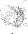
Fig. 1 is a partially cut away perspective view of an embodiment of a nozzle assembly constructed in accordance with the present disclosure, showing the air cap and air swirler outer wall in cross-section; -
Fig. 2 is a cross-sectional side elevation view of a portion of the nozzle assembly ofFig. 1 , showing the inlets of the air wipe passages; and -
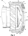
Fig. 3 is a cross-sectional side elevation view of a nozzle assembly like that inFig. 1 , showing an integral air cap and air swirler. - Reference will now be made to the drawings wherein like reference numerals identify similar structural features or aspects of the subject disclosure. For purposes of explanation and illustration, and not limitation, a partial view of an embodiment of a nozzle assembly in accordance with the disclosure is shown in
Fig. 1 and is designated generally byreference character 100. Other embodiments of systems in accordance with the disclosure, or aspects thereof, are provided inFigs. 2-3 , as will be described. The systems and methods described herein can be used to provide wipe air or gas to the downstream facing surfaces of air caps in nozzle assemblies such as used in fuel injectors for gas turbine engines. - The
nozzle assembly 100 includes an air swirlerouter wall 102. Anair cap 104 is connected to thenozzle assembly 100 outboard of the air swirlerouter wall 102. An air swirlerinner wall 106 is connected to the air swirlerouter wall 102 by a plurality ofair swirl vanes 108. In addition to or in lieu ofswirl vanes 108, straight vanes or standoffs can be used. One or morefuel circuit components nozzle assembly 100 inboard of the air swirlerinner wall 106. Agas fuel circuit 116 is defined inboard of the air swirlerinner wall 106. Liquid fuel circuits are defined inboard of thegas fuel circuit 116, e.g. inboard ofcomponents - The
air cap 104 is affixed to thenozzle assembly 100 and is a downstream facing component of thenozzle assembly 100. Theair cap 104 includes a plurality ofair wipe passages 118 with outlets 120 defined in a circumferential direction C around a downstream facingsurface 122 of theair cap 104. An airwipe feed passage 124 is defined between the air swirlerouter wall 102 and theair cap 104. The airwipe feed passage 124 is in fluid commination with theair wipe passages 118 to supply air (e.g. T3 or compressor discharge air) for wiping the downstream facingsurface 122 of theair cap 104. The airwipe feed passage 124 can optionally be connected to a gaseous fuel source to issue gaseous fuel through theair wipe passages 118, or the air wipe passages can be connected to a gaseous fuel source via a separate passage from the air wipe feed passage 124 (see, e.g.,optional gas passage 138 in broken lines inFig. 3 ). - The
air cap 104 defines acentral outlet orifice 126 therethrough. Theair wipe passages 118 define a plurality of concentric airwipe passage rings 128 outletting on the downstream facingsurface 122 of theair cap 104. InFig. 1 , there are three concentric airwipe passage rings 128, however those skilled in the art having had the benefit of this disclosure will readily appreciate that any suitable number of air wipe passage rings can be used without departing from the scope of this disclosure. Eachair wipe passage 118 extends from aninterior surface 130 of theair cap 104 to the downstream facingsurface 122 of theair cap 104, winding in a helical direction H about a spray axis A of theair cap 104. The downstream facingsurface 122 of theair cap 104 includes a circumferentially extending series ofsteps 134. Eachstep 134 defines a respective circumferentially facingoutlet face 132 from which emerge one or more of the outlets 120 of theair wipe passages 118. There is at least one radial cross-section, e.g. the cross section shown inFig. 1 orFig. 2 , of theair cap 104 wherein theair wipe passages 118 are layered at least two deep in the axial direction, i.e. along the spray axis A. InFigs. 1 and2 , the cross-sections shown have theair wipe passages 118 layered three deep in the axial direction along axis A. This allows for internal cooling of theair cap 104. - In
Figs. 1 and2 , theair cap 104 is a separate component from the air swirlerouter wall 102, wherein theair cap 104 is mounted to the air swirlerouter wall 102, e.g., by brazing. It is also contemplated that theair cap 104, air swirlerinner wall 106, air swirlerouter wall 102, andair swirl vanes 108 can all be a single integral component as shown inFig. 3 . This can be accomplished using additive manufacturing, for example. A plurality of purely axialoriented wipe orifices 136 can be included in addition to the circumferentially orientedair wipe passages 118. - The methods and systems of the present disclosure, as described above and shown in the drawings, can provide for air or gas issued directly to areas of recirculation by utilizing internal wipe passages, without requiring any changes to overall nozzle assembly envelope. While the apparatus and methods of the subject disclosure have been shown and described with reference to preferred embodiments, those skilled in the art will readily appreciate that changes and/or modifications may be made thereto without departing from the scope of the invention as defined by the claims.
Claims (15)
- An apparatus comprising:
an air cap (104) configured to be affixed to a nozzle assembly (100) as a downstream facing component of the nozzle assembly, wherein the air cap includes a plurality of air wipe passages (118) with outlets (120) defined in a circumferential direction around a downstream facing surface (122) of the air cap. - The apparatus as recited in claim 1, wherein the air wipe passages define a plurality of concentric air wipe passage rings (128) outletting on the downstream facing surface of the air cap.
- The apparatus as recited in claim 1 or 2, wherein each air wipe passage extends from an interior surface (130) of the air cap to the downstream facing surface of the air cap, winding in a helical direction about a spray axis of the air cap.
- The apparatus as recited in any preceding claim, wherein the downstream facing surface of the air cap includes a circumferentially extending series of steps (134), each step defining a circumferentially facing outlet face from which one or more of the outlets emerge.
- The apparatus as recited in any preceding claim, further comprising the nozzle assembly (100) including:
an outer wall (102) wherein the air cap is connected to the nozzle assembly outboard of the outer wall. - The apparatus as recited in claim 5, wherein the nozzle assembly further comprises:
an inner wall (106) connected to the outer wall by a plurality of air swirl vanes (108), straight vanes, and/or standoffs. - The apparatus as recited in claim 6, wherein the nozzle assembly further comprises one or more fuel circuit components (110, 112, 114) connected to the nozzle assembly inboard of the inner wall.
- The apparatus as recited in claim 7, wherein a gas fuel circuit (116) is defined inboard of the inner wall.
- The apparatus as recited in claim 8, wherein one or more liquid circuits are defined inboard of the gas fuel circuit.
- The apparatus as recited in claim 7, wherein the air cap, inner wall, and outer wall are a single integral component.
- The apparatus as recited in claim 7, wherein the air cap is a separate component from the outer wall, wherein the air cap is mounted to the outer wall.
- The apparatus as recited in claim 7, wherein an air wipe feed passage (124) is defined between the outer wall and the air cap, wherein the air wipe feed passage is in fluid commination with the air wipe passages.
- The apparatus as recited in claim 12, wherein the air wipe feed passage is connected to a gaseous fuel source to issue gaseous fuel through the air wipe passages.
- The apparatus as recited in any preceding claim, wherein the air cap defines a central outlet orifice (126) therethrough.
- The apparatus as recited in any preceding claim, wherein there is at least one radial cross-section of the air cap wherein the air wipe passages are layered at least two deep in an axial direction.
Applications Claiming Priority (1)
| Application Number | Priority Date | Filing Date | Title |
|---|---|---|---|
| US202063014935P | 2020-04-24 | 2020-04-24 |
Publications (2)
| Publication Number | Publication Date |
|---|---|
| EP3901520A1 true EP3901520A1 (en) | 2021-10-27 |
| EP3901520B1 EP3901520B1 (en) | 2024-03-20 |
Family
ID=75674690
Family Applications (1)
| Application Number | Title | Priority Date | Filing Date |
|---|---|---|---|
| EP21170411.9A Active EP3901520B1 (en) | 2020-04-24 | 2021-04-26 | Nozzle assembly with air cap |
Country Status (2)
| Country | Link |
|---|---|
| US (2) | US11454395B2 (en) |
| EP (1) | EP3901520B1 (en) |
Families Citing this family (1)
| Publication number | Priority date | Publication date | Assignee | Title |
|---|---|---|---|---|
| US20250369613A1 (en) * | 2024-06-04 | 2025-12-04 | Pratt & Whitney Canada Corp. | Effusion cooled fuel nozzle tip |
Citations (5)
| Publication number | Priority date | Publication date | Assignee | Title |
|---|---|---|---|---|
| US20140020397A1 (en) * | 2011-02-18 | 2014-01-23 | Ulf Nilsson | Combustion chamber with a wall section and a brim element |
| US20140246518A1 (en) * | 2013-03-01 | 2014-09-04 | Delavan Inc | Fuel nozzle with discrete jet inner air swirler |
| EP3054219A1 (en) * | 2015-02-05 | 2016-08-10 | Delavan, Inc. | Air shrouds with air wipes |
| US20180010563A1 (en) * | 2012-02-16 | 2018-01-11 | Delavan Inc. | Variable angle multi-point injection |
| US20190376690A1 (en) * | 2018-06-11 | 2019-12-12 | Woodward, Inc. | Pre-swirl pressure atomizing tip |
Family Cites Families (17)
| Publication number | Priority date | Publication date | Assignee | Title |
|---|---|---|---|---|
| CA1259197A (en) | 1985-02-13 | 1989-09-12 | Alan D. Bennett | High reliability fuel oil nozzle for a gas turbine |
| US4914918A (en) * | 1988-09-26 | 1990-04-10 | United Technologies Corporation | Combustor segmented deflector |
| US6363724B1 (en) * | 2000-08-31 | 2002-04-02 | General Electric Company | Gas only nozzle fuel tip |
| US7007864B2 (en) | 2002-11-08 | 2006-03-07 | United Technologies Corporation | Fuel nozzle design |
| US8607569B2 (en) * | 2009-07-01 | 2013-12-17 | General Electric Company | Methods and systems to thermally protect fuel nozzles in combustion systems |
| US8555649B2 (en) | 2009-09-02 | 2013-10-15 | Pratt & Whitney Canada Corp. | Fuel nozzle swirler assembly |
| EP2434221A1 (en) * | 2010-09-22 | 2012-03-28 | Siemens Aktiengesellschaft | Method and arrangement for injecting an emulsion into a flame |
| US8919132B2 (en) * | 2011-05-18 | 2014-12-30 | Solar Turbines Inc. | Method of operating a gas turbine engine |
| US9309809B2 (en) * | 2013-01-23 | 2016-04-12 | General Electric Company | Effusion plate using additive manufacturing methods |
| WO2014189602A2 (en) * | 2013-03-14 | 2014-11-27 | United Technologies Corporation | Hollow-wall heat shield for fuel injector component |
| GB2521127B (en) | 2013-12-10 | 2016-10-19 | Rolls Royce Plc | Fuel spray nozzle |
| US9551490B2 (en) * | 2014-04-08 | 2017-01-24 | General Electric Company | System for cooling a fuel injector extending into a combustion gas flow field and method for manufacture |
| US10385809B2 (en) * | 2015-03-31 | 2019-08-20 | Delavan Inc. | Fuel nozzles |
| US9863638B2 (en) * | 2015-04-01 | 2018-01-09 | Delavan Inc. | Air shrouds with improved air wiping |
| WO2017006690A1 (en) * | 2015-07-03 | 2017-01-12 | 三菱日立パワーシステムズ株式会社 | Combustor nozzle, gas turbine combustor, gas turbine, cover ring, and method for manufacturing combustor nozzle |
| US20170248318A1 (en) * | 2016-02-26 | 2017-08-31 | General Electric Company | Pilot nozzles in gas turbine combustors |
| US10801726B2 (en) * | 2017-09-21 | 2020-10-13 | General Electric Company | Combustor mixer purge cooling structure |
-
2021
- 2021-04-20 US US17/235,242 patent/US11454395B2/en active Active
- 2021-04-26 EP EP21170411.9A patent/EP3901520B1/en active Active
-
2022
- 2022-05-26 US US17/825,381 patent/US11774097B2/en active Active
Patent Citations (5)
| Publication number | Priority date | Publication date | Assignee | Title |
|---|---|---|---|---|
| US20140020397A1 (en) * | 2011-02-18 | 2014-01-23 | Ulf Nilsson | Combustion chamber with a wall section and a brim element |
| US20180010563A1 (en) * | 2012-02-16 | 2018-01-11 | Delavan Inc. | Variable angle multi-point injection |
| US20140246518A1 (en) * | 2013-03-01 | 2014-09-04 | Delavan Inc | Fuel nozzle with discrete jet inner air swirler |
| EP3054219A1 (en) * | 2015-02-05 | 2016-08-10 | Delavan, Inc. | Air shrouds with air wipes |
| US20190376690A1 (en) * | 2018-06-11 | 2019-12-12 | Woodward, Inc. | Pre-swirl pressure atomizing tip |
Also Published As
| Publication number | Publication date |
|---|---|
| US11774097B2 (en) | 2023-10-03 |
| US11454395B2 (en) | 2022-09-27 |
| US20220282868A1 (en) | 2022-09-08 |
| US20210332980A1 (en) | 2021-10-28 |
| EP3901520B1 (en) | 2024-03-20 |
Similar Documents
| Publication | Publication Date | Title |
|---|---|---|
| EP3828468B1 (en) | System comprising a combustor and turbine inlet stator vanes | |
| EP3341656B1 (en) | Fuel nozzle assembly for a gas turbine | |
| US9851105B2 (en) | Self-cooled orifice structure | |
| US10612781B2 (en) | Combustor wall aperture body with cooling circuit | |
| US20230296054A1 (en) | Nozzles with internal manifolding | |
| US12038176B2 (en) | Coupling a fuel nozzle purge flow directly to a swirler | |
| US7000400B2 (en) | Temperature variance reduction using variable penetration dilution jets | |
| US10731860B2 (en) | Air shrouds with air wipes | |
| US10612784B2 (en) | Nozzle assembly for a dual-fuel fuel nozzle | |
| US11994295B2 (en) | Multi pressure drop swirler ferrule plate | |
| US10823418B2 (en) | Gas turbine engine combustor comprising air inlet tubes arranged around the combustor | |
| EP3901520B1 (en) | Nozzle assembly with air cap | |
| EP4123224B1 (en) | Cartridge tip for turbomachine combustor | |
| US10041677B2 (en) | Combustion liner for use in a combustor assembly and method of manufacturing | |
| US11092076B2 (en) | Turbine engine with combustor | |
| US20180363899A1 (en) | Dual-fuel fuel nozzle with air shield | |
| US10663171B2 (en) | Dual-fuel fuel nozzle with gas and liquid fuel capability | |
| US10982856B2 (en) | Fuel nozzle with sleeves for thermal protection | |
| CN114483321A (en) | Integrated combustion nozzle with integrated head end | |
| US11774093B2 (en) | Burner cooling structures |
Legal Events
| Date | Code | Title | Description |
|---|---|---|---|
| PUAI | Public reference made under article 153(3) epc to a published international application that has entered the european phase |
Free format text: ORIGINAL CODE: 0009012 |
|
| STAA | Information on the status of an ep patent application or granted ep patent |
Free format text: STATUS: THE APPLICATION HAS BEEN PUBLISHED |
|
| AK | Designated contracting states |
Kind code of ref document: A1 Designated state(s): AL AT BE BG CH CY CZ DE DK EE ES FI FR GB GR HR HU IE IS IT LI LT LU LV MC MK MT NL NO PL PT RO RS SE SI SK SM TR |
|
| B565 | Issuance of search results under rule 164(2) epc |
Effective date: 20210914 |
|
| STAA | Information on the status of an ep patent application or granted ep patent |
Free format text: STATUS: REQUEST FOR EXAMINATION WAS MADE |
|
| RAP3 | Party data changed (applicant data changed or rights of an application transferred) |
Owner name: COLLINS ENGINE NOZZLES, INC. |
|
| 17P | Request for examination filed |
Effective date: 20220427 |
|
| RBV | Designated contracting states (corrected) |
Designated state(s): AL AT BE BG CH CY CZ DE DK EE ES FI FR GB GR HR HU IE IS IT LI LT LU LV MC MK MT NL NO PL PT RO RS SE SI SK SM TR |
|
| STAA | Information on the status of an ep patent application or granted ep patent |
Free format text: STATUS: EXAMINATION IS IN PROGRESS |
|
| 17Q | First examination report despatched |
Effective date: 20230112 |
|
| GRAP | Despatch of communication of intention to grant a patent |
Free format text: ORIGINAL CODE: EPIDOSNIGR1 |
|
| STAA | Information on the status of an ep patent application or granted ep patent |
Free format text: STATUS: GRANT OF PATENT IS INTENDED |
|
| INTG | Intention to grant announced |
Effective date: 20230929 |
|
| P01 | Opt-out of the competence of the unified patent court (upc) registered |
Effective date: 20230922 |
|
| GRAS | Grant fee paid |
Free format text: ORIGINAL CODE: EPIDOSNIGR3 |
|
| GRAA | (expected) grant |
Free format text: ORIGINAL CODE: 0009210 |
|
| STAA | Information on the status of an ep patent application or granted ep patent |
Free format text: STATUS: THE PATENT HAS BEEN GRANTED |
|
| AK | Designated contracting states |
Kind code of ref document: B1 Designated state(s): AL AT BE BG CH CY CZ DE DK EE ES FI FR GB GR HR HU IE IS IT LI LT LU LV MC MK MT NL NO PL PT RO RS SE SI SK SM TR |
|
| REG | Reference to a national code |
Ref country code: GB Ref legal event code: FG4D |
|
| REG | Reference to a national code |
Ref country code: CH Ref legal event code: EP |
|
| REG | Reference to a national code |
Ref country code: DE Ref legal event code: R096 Ref document number: 602021010557 Country of ref document: DE |
|
| REG | Reference to a national code |
Ref country code: IE Ref legal event code: FG4D |
|
| PG25 | Lapsed in a contracting state [announced via postgrant information from national office to epo] |
Ref country code: LT Free format text: LAPSE BECAUSE OF FAILURE TO SUBMIT A TRANSLATION OF THE DESCRIPTION OR TO PAY THE FEE WITHIN THE PRESCRIBED TIME-LIMIT Effective date: 20240320 |
|
| REG | Reference to a national code |
Ref country code: LT Ref legal event code: MG9D |
|
| PG25 | Lapsed in a contracting state [announced via postgrant information from national office to epo] |
Ref country code: GR Free format text: LAPSE BECAUSE OF FAILURE TO SUBMIT A TRANSLATION OF THE DESCRIPTION OR TO PAY THE FEE WITHIN THE PRESCRIBED TIME-LIMIT Effective date: 20240621 |
|
| PG25 | Lapsed in a contracting state [announced via postgrant information from national office to epo] |
Ref country code: RS Free format text: LAPSE BECAUSE OF FAILURE TO SUBMIT A TRANSLATION OF THE DESCRIPTION OR TO PAY THE FEE WITHIN THE PRESCRIBED TIME-LIMIT Effective date: 20240620 Ref country code: HR Free format text: LAPSE BECAUSE OF FAILURE TO SUBMIT A TRANSLATION OF THE DESCRIPTION OR TO PAY THE FEE WITHIN THE PRESCRIBED TIME-LIMIT Effective date: 20240320 |
|
| REG | Reference to a national code |
Ref country code: NL Ref legal event code: MP Effective date: 20240320 |
|
| PG25 | Lapsed in a contracting state [announced via postgrant information from national office to epo] |
Ref country code: RS Free format text: LAPSE BECAUSE OF FAILURE TO SUBMIT A TRANSLATION OF THE DESCRIPTION OR TO PAY THE FEE WITHIN THE PRESCRIBED TIME-LIMIT Effective date: 20240620 Ref country code: NO Free format text: LAPSE BECAUSE OF FAILURE TO SUBMIT A TRANSLATION OF THE DESCRIPTION OR TO PAY THE FEE WITHIN THE PRESCRIBED TIME-LIMIT Effective date: 20240620 Ref country code: LT Free format text: LAPSE BECAUSE OF FAILURE TO SUBMIT A TRANSLATION OF THE DESCRIPTION OR TO PAY THE FEE WITHIN THE PRESCRIBED TIME-LIMIT Effective date: 20240320 Ref country code: HR Free format text: LAPSE BECAUSE OF FAILURE TO SUBMIT A TRANSLATION OF THE DESCRIPTION OR TO PAY THE FEE WITHIN THE PRESCRIBED TIME-LIMIT Effective date: 20240320 Ref country code: GR Free format text: LAPSE BECAUSE OF FAILURE TO SUBMIT A TRANSLATION OF THE DESCRIPTION OR TO PAY THE FEE WITHIN THE PRESCRIBED TIME-LIMIT Effective date: 20240621 Ref country code: FI Free format text: LAPSE BECAUSE OF FAILURE TO SUBMIT A TRANSLATION OF THE DESCRIPTION OR TO PAY THE FEE WITHIN THE PRESCRIBED TIME-LIMIT Effective date: 20240320 Ref country code: BG Free format text: LAPSE BECAUSE OF FAILURE TO SUBMIT A TRANSLATION OF THE DESCRIPTION OR TO PAY THE FEE WITHIN THE PRESCRIBED TIME-LIMIT Effective date: 20240320 |
|
| REG | Reference to a national code |
Ref country code: AT Ref legal event code: MK05 Ref document number: 1668116 Country of ref document: AT Kind code of ref document: T Effective date: 20240320 |
|
| PG25 | Lapsed in a contracting state [announced via postgrant information from national office to epo] |
Ref country code: SE Free format text: LAPSE BECAUSE OF FAILURE TO SUBMIT A TRANSLATION OF THE DESCRIPTION OR TO PAY THE FEE WITHIN THE PRESCRIBED TIME-LIMIT Effective date: 20240320 Ref country code: LV Free format text: LAPSE BECAUSE OF FAILURE TO SUBMIT A TRANSLATION OF THE DESCRIPTION OR TO PAY THE FEE WITHIN THE PRESCRIBED TIME-LIMIT Effective date: 20240320 |
|
| PG25 | Lapsed in a contracting state [announced via postgrant information from national office to epo] |
Ref country code: NL Free format text: LAPSE BECAUSE OF FAILURE TO SUBMIT A TRANSLATION OF THE DESCRIPTION OR TO PAY THE FEE WITHIN THE PRESCRIBED TIME-LIMIT Effective date: 20240320 |
|
| PG25 | Lapsed in a contracting state [announced via postgrant information from national office to epo] |
Ref country code: NL Free format text: LAPSE BECAUSE OF FAILURE TO SUBMIT A TRANSLATION OF THE DESCRIPTION OR TO PAY THE FEE WITHIN THE PRESCRIBED TIME-LIMIT Effective date: 20240320 |
|
| PG25 | Lapsed in a contracting state [announced via postgrant information from national office to epo] |
Ref country code: IS Free format text: LAPSE BECAUSE OF FAILURE TO SUBMIT A TRANSLATION OF THE DESCRIPTION OR TO PAY THE FEE WITHIN THE PRESCRIBED TIME-LIMIT Effective date: 20240720 |
|
| PG25 | Lapsed in a contracting state [announced via postgrant information from national office to epo] |
Ref country code: PT Free format text: LAPSE BECAUSE OF FAILURE TO SUBMIT A TRANSLATION OF THE DESCRIPTION OR TO PAY THE FEE WITHIN THE PRESCRIBED TIME-LIMIT Effective date: 20240722 Ref country code: SM Free format text: LAPSE BECAUSE OF FAILURE TO SUBMIT A TRANSLATION OF THE DESCRIPTION OR TO PAY THE FEE WITHIN THE PRESCRIBED TIME-LIMIT Effective date: 20240320 |
|
| PG25 | Lapsed in a contracting state [announced via postgrant information from national office to epo] |
Ref country code: ES Free format text: LAPSE BECAUSE OF FAILURE TO SUBMIT A TRANSLATION OF THE DESCRIPTION OR TO PAY THE FEE WITHIN THE PRESCRIBED TIME-LIMIT Effective date: 20240320 |
|
| PG25 | Lapsed in a contracting state [announced via postgrant information from national office to epo] |
Ref country code: EE Free format text: LAPSE BECAUSE OF FAILURE TO SUBMIT A TRANSLATION OF THE DESCRIPTION OR TO PAY THE FEE WITHIN THE PRESCRIBED TIME-LIMIT Effective date: 20240320 Ref country code: CZ Free format text: LAPSE BECAUSE OF FAILURE TO SUBMIT A TRANSLATION OF THE DESCRIPTION OR TO PAY THE FEE WITHIN THE PRESCRIBED TIME-LIMIT Effective date: 20240320 |
|
| PG25 | Lapsed in a contracting state [announced via postgrant information from national office to epo] |
Ref country code: AT Free format text: LAPSE BECAUSE OF FAILURE TO SUBMIT A TRANSLATION OF THE DESCRIPTION OR TO PAY THE FEE WITHIN THE PRESCRIBED TIME-LIMIT Effective date: 20240320 |
|
| PG25 | Lapsed in a contracting state [announced via postgrant information from national office to epo] |
Ref country code: PL Free format text: LAPSE BECAUSE OF FAILURE TO SUBMIT A TRANSLATION OF THE DESCRIPTION OR TO PAY THE FEE WITHIN THE PRESCRIBED TIME-LIMIT Effective date: 20240320 |
|
| PG25 | Lapsed in a contracting state [announced via postgrant information from national office to epo] |
Ref country code: SK Free format text: LAPSE BECAUSE OF FAILURE TO SUBMIT A TRANSLATION OF THE DESCRIPTION OR TO PAY THE FEE WITHIN THE PRESCRIBED TIME-LIMIT Effective date: 20240320 |
|
| PG25 | Lapsed in a contracting state [announced via postgrant information from national office to epo] |
Ref country code: SM Free format text: LAPSE BECAUSE OF FAILURE TO SUBMIT A TRANSLATION OF THE DESCRIPTION OR TO PAY THE FEE WITHIN THE PRESCRIBED TIME-LIMIT Effective date: 20240320 Ref country code: SK Free format text: LAPSE BECAUSE OF FAILURE TO SUBMIT A TRANSLATION OF THE DESCRIPTION OR TO PAY THE FEE WITHIN THE PRESCRIBED TIME-LIMIT Effective date: 20240320 Ref country code: RO Free format text: LAPSE BECAUSE OF FAILURE TO SUBMIT A TRANSLATION OF THE DESCRIPTION OR TO PAY THE FEE WITHIN THE PRESCRIBED TIME-LIMIT Effective date: 20240320 Ref country code: PT Free format text: LAPSE BECAUSE OF FAILURE TO SUBMIT A TRANSLATION OF THE DESCRIPTION OR TO PAY THE FEE WITHIN THE PRESCRIBED TIME-LIMIT Effective date: 20240722 Ref country code: PL Free format text: LAPSE BECAUSE OF FAILURE TO SUBMIT A TRANSLATION OF THE DESCRIPTION OR TO PAY THE FEE WITHIN THE PRESCRIBED TIME-LIMIT Effective date: 20240320 Ref country code: IS Free format text: LAPSE BECAUSE OF FAILURE TO SUBMIT A TRANSLATION OF THE DESCRIPTION OR TO PAY THE FEE WITHIN THE PRESCRIBED TIME-LIMIT Effective date: 20240720 Ref country code: ES Free format text: LAPSE BECAUSE OF FAILURE TO SUBMIT A TRANSLATION OF THE DESCRIPTION OR TO PAY THE FEE WITHIN THE PRESCRIBED TIME-LIMIT Effective date: 20240320 Ref country code: EE Free format text: LAPSE BECAUSE OF FAILURE TO SUBMIT A TRANSLATION OF THE DESCRIPTION OR TO PAY THE FEE WITHIN THE PRESCRIBED TIME-LIMIT Effective date: 20240320 Ref country code: CZ Free format text: LAPSE BECAUSE OF FAILURE TO SUBMIT A TRANSLATION OF THE DESCRIPTION OR TO PAY THE FEE WITHIN THE PRESCRIBED TIME-LIMIT Effective date: 20240320 Ref country code: AT Free format text: LAPSE BECAUSE OF FAILURE TO SUBMIT A TRANSLATION OF THE DESCRIPTION OR TO PAY THE FEE WITHIN THE PRESCRIBED TIME-LIMIT Effective date: 20240320 |
|
| REG | Reference to a national code |
Ref country code: CH Ref legal event code: PL |
|
| PG25 | Lapsed in a contracting state [announced via postgrant information from national office to epo] |
Ref country code: IT Free format text: LAPSE BECAUSE OF FAILURE TO SUBMIT A TRANSLATION OF THE DESCRIPTION OR TO PAY THE FEE WITHIN THE PRESCRIBED TIME-LIMIT Effective date: 20240320 |
|
| PG25 | Lapsed in a contracting state [announced via postgrant information from national office to epo] |
Ref country code: LU Free format text: LAPSE BECAUSE OF NON-PAYMENT OF DUE FEES Effective date: 20240426 |
|
| REG | Reference to a national code |
Ref country code: DE Ref legal event code: R097 Ref document number: 602021010557 Country of ref document: DE |
|
| REG | Reference to a national code |
Ref country code: BE Ref legal event code: MM Effective date: 20240430 |
|
| PG25 | Lapsed in a contracting state [announced via postgrant information from national office to epo] |
Ref country code: LU Free format text: LAPSE BECAUSE OF NON-PAYMENT OF DUE FEES Effective date: 20240426 Ref country code: IT Free format text: LAPSE BECAUSE OF FAILURE TO SUBMIT A TRANSLATION OF THE DESCRIPTION OR TO PAY THE FEE WITHIN THE PRESCRIBED TIME-LIMIT Effective date: 20240320 |
|
| PG25 | Lapsed in a contracting state [announced via postgrant information from national office to epo] |
Ref country code: MC Free format text: LAPSE BECAUSE OF FAILURE TO SUBMIT A TRANSLATION OF THE DESCRIPTION OR TO PAY THE FEE WITHIN THE PRESCRIBED TIME-LIMIT Effective date: 20240320 |
|
| PG25 | Lapsed in a contracting state [announced via postgrant information from national office to epo] |
Ref country code: DK Free format text: LAPSE BECAUSE OF FAILURE TO SUBMIT A TRANSLATION OF THE DESCRIPTION OR TO PAY THE FEE WITHIN THE PRESCRIBED TIME-LIMIT Effective date: 20240320 |
|
| PG25 | Lapsed in a contracting state [announced via postgrant information from national office to epo] |
Ref country code: BE Free format text: LAPSE BECAUSE OF NON-PAYMENT OF DUE FEES Effective date: 20240430 |
|
| PLBE | No opposition filed within time limit |
Free format text: ORIGINAL CODE: 0009261 |
|
| STAA | Information on the status of an ep patent application or granted ep patent |
Free format text: STATUS: NO OPPOSITION FILED WITHIN TIME LIMIT |
|
| PG25 | Lapsed in a contracting state [announced via postgrant information from national office to epo] |
Ref country code: MC Free format text: LAPSE BECAUSE OF FAILURE TO SUBMIT A TRANSLATION OF THE DESCRIPTION OR TO PAY THE FEE WITHIN THE PRESCRIBED TIME-LIMIT Effective date: 20240320 Ref country code: DK Free format text: LAPSE BECAUSE OF FAILURE TO SUBMIT A TRANSLATION OF THE DESCRIPTION OR TO PAY THE FEE WITHIN THE PRESCRIBED TIME-LIMIT Effective date: 20240320 Ref country code: BE Free format text: LAPSE BECAUSE OF NON-PAYMENT OF DUE FEES Effective date: 20240430 Ref country code: CH Free format text: LAPSE BECAUSE OF NON-PAYMENT OF DUE FEES Effective date: 20240430 |
|
| 26N | No opposition filed |
Effective date: 20241223 |
|
| PG25 | Lapsed in a contracting state [announced via postgrant information from national office to epo] |
Ref country code: IE Free format text: LAPSE BECAUSE OF NON-PAYMENT OF DUE FEES Effective date: 20240426 |
|
| PG25 | Lapsed in a contracting state [announced via postgrant information from national office to epo] |
Ref country code: SI Free format text: LAPSE BECAUSE OF FAILURE TO SUBMIT A TRANSLATION OF THE DESCRIPTION OR TO PAY THE FEE WITHIN THE PRESCRIBED TIME-LIMIT Effective date: 20240320 |
|
| PG25 | Lapsed in a contracting state [announced via postgrant information from national office to epo] |
Ref country code: CY Free format text: LAPSE BECAUSE OF FAILURE TO SUBMIT A TRANSLATION OF THE DESCRIPTION OR TO PAY THE FEE WITHIN THE PRESCRIBED TIME-LIMIT; INVALID AB INITIO Effective date: 20210426 |
|
| PG25 | Lapsed in a contracting state [announced via postgrant information from national office to epo] |
Ref country code: HU Free format text: LAPSE BECAUSE OF FAILURE TO SUBMIT A TRANSLATION OF THE DESCRIPTION OR TO PAY THE FEE WITHIN THE PRESCRIBED TIME-LIMIT; INVALID AB INITIO Effective date: 20210426 |
|
| PGFP | Annual fee paid to national office [announced via postgrant information from national office to epo] |
Ref country code: GB Payment date: 20260319 Year of fee payment: 6 |
|
| PGFP | Annual fee paid to national office [announced via postgrant information from national office to epo] |
Ref country code: FR Payment date: 20260319 Year of fee payment: 6 |
|
| PG25 | Lapsed in a contracting state [announced via postgrant information from national office to epo] |
Ref country code: TR Free format text: LAPSE BECAUSE OF FAILURE TO SUBMIT A TRANSLATION OF THE DESCRIPTION OR TO PAY THE FEE WITHIN THE PRESCRIBED TIME-LIMIT Effective date: 20240320 |
|
| PGFP | Annual fee paid to national office [announced via postgrant information from national office to epo] |
Ref country code: DE Payment date: 20260319 Year of fee payment: 6 |