EP3901470A1 - Centrifugal blower, blowing device, air conditioner, and refrigeration cycle device - Google Patents
Centrifugal blower, blowing device, air conditioner, and refrigeration cycle device Download PDFInfo
- Publication number
- EP3901470A1 EP3901470A1 EP18943779.1A EP18943779A EP3901470A1 EP 3901470 A1 EP3901470 A1 EP 3901470A1 EP 18943779 A EP18943779 A EP 18943779A EP 3901470 A1 EP3901470 A1 EP 3901470A1
- Authority
- EP
- European Patent Office
- Prior art keywords
- peripheral wall
- fan
- centrifugal fan
- rotation shaft
- distance
- Prior art date
- Legal status (The legal status is an assumption and is not a legal conclusion. Google has not performed a legal analysis and makes no representation as to the accuracy of the status listed.)
- Granted
Links
Images




Classifications
-
- F—MECHANICAL ENGINEERING; LIGHTING; HEATING; WEAPONS; BLASTING
- F04—POSITIVE - DISPLACEMENT MACHINES FOR LIQUIDS; PUMPS FOR LIQUIDS OR ELASTIC FLUIDS
- F04D—NON-POSITIVE-DISPLACEMENT PUMPS
- F04D29/00—Details, component parts, or accessories
- F04D29/40—Casings; Connections of working fluid
- F04D29/42—Casings; Connections of working fluid for radial or helico-centrifugal pumps
- F04D29/4206—Casings; Connections of working fluid for radial or helico-centrifugal pumps especially adapted for elastic fluid pumps
- F04D29/4226—Fan casings
-
- F—MECHANICAL ENGINEERING; LIGHTING; HEATING; WEAPONS; BLASTING
- F04—POSITIVE - DISPLACEMENT MACHINES FOR LIQUIDS; PUMPS FOR LIQUIDS OR ELASTIC FLUIDS
- F04D—NON-POSITIVE-DISPLACEMENT PUMPS
- F04D29/00—Details, component parts, or accessories
- F04D29/40—Casings; Connections of working fluid
- F04D29/42—Casings; Connections of working fluid for radial or helico-centrifugal pumps
- F04D29/4206—Casings; Connections of working fluid for radial or helico-centrifugal pumps especially adapted for elastic fluid pumps
- F04D29/4226—Fan casings
- F04D29/424—Double entry casings
-
- F—MECHANICAL ENGINEERING; LIGHTING; HEATING; WEAPONS; BLASTING
- F04—POSITIVE - DISPLACEMENT MACHINES FOR LIQUIDS; PUMPS FOR LIQUIDS OR ELASTIC FLUIDS
- F04D—NON-POSITIVE-DISPLACEMENT PUMPS
- F04D29/00—Details, component parts, or accessories
- F04D29/40—Casings; Connections of working fluid
- F04D29/42—Casings; Connections of working fluid for radial or helico-centrifugal pumps
- F04D29/44—Fluid-guiding means, e.g. diffusers
- F04D29/441—Fluid-guiding means, e.g. diffusers especially adapted for elastic fluid pumps
-
- F—MECHANICAL ENGINEERING; LIGHTING; HEATING; WEAPONS; BLASTING
- F04—POSITIVE - DISPLACEMENT MACHINES FOR LIQUIDS; PUMPS FOR LIQUIDS OR ELASTIC FLUIDS
- F04D—NON-POSITIVE-DISPLACEMENT PUMPS
- F04D29/00—Details, component parts, or accessories
- F04D29/66—Combating cavitation, whirls, noise, vibration or the like; Balancing
- F04D29/661—Combating cavitation, whirls, noise, vibration or the like; Balancing especially adapted for elastic fluid pumps
- F04D29/663—Sound attenuation
-
- F—MECHANICAL ENGINEERING; LIGHTING; HEATING; WEAPONS; BLASTING
- F24—HEATING; RANGES; VENTILATING
- F24F—AIR-CONDITIONING; AIR-HUMIDIFICATION; VENTILATION; USE OF AIR CURRENTS FOR SCREENING
- F24F7/00—Ventilation
- F24F7/007—Ventilation with forced flow
Definitions
- the present disclosure relates to a centrifugal fan including a scroll casing; and an air-sending device, an air-conditioning apparatus, and a refrigeration cycle apparatus including the centrifugal fan.
- a conventional centrifugal fan includes a fan including a main plate on a disk and a plurality of blades in a scroll casing, and a tongue portion required for blowing out, in the centrifugal direction, the air that has entered from an air inlet formed at an end of the fan in the rotation axis direction, and increasing the pressure thereof.
- the centrifugal fan when the airflow in the scroll casing that has entered from the air inlet moves toward an air outlet, part of the airflow branches off at the tongue portion and enters the scroll again.
- a gas passage formed between the tongue portion and the blades suddenly narrows, so that a large pressure difference is generated between the airflow moving toward the air outlet and the airflow entering the scroll again. This causes an increase in noise level.
- Patent Literature 1 Japanese Unexamined Patent Application Publication No.09 - 242697
- the centrifugal fan of Patent Literature 1 since the position where the clearance between the scroll casing and the outer periphery of the fan is minimum is shifted from the tongue portion in the blade rotation direction, the volume of gas flowing through a flow passage from the tongue portion to this position is reduced. Therefore, the centrifugal fan of Patent Literature 1 may not be able to efficiently increase the pressure in a scroll portion formed in a volute shape.
- the present disclosure has been made to solve the above problem, and an object thereof is to provide a centrifugal fan, an air-sending device, an air-conditioning apparatus, and a refrigeration cycle apparatus that are capable of efficiently increasing the pressure in a scroll portion even in the case where the position where the clearance between a scroll casing and an outer periphery of a fan is minimum is shifted from a tongue portion in the blade rotation direction.
- a centrifugal fan includes a fan configured to be driven to rotate; and a scroll casing housing the fan; the scroll casing including a peripheral wall having a volute shape having an inner end of a spiral thereof at a boundary with a tongue portion of the scroll casing, the tongue portion being configured to guide airflow generated by the fan, the peripheral wall including, when a portion at the peripheral wall at which a distance between the peripheral wall and a rotation shaft of the fan is minimum is defined as a closest portion, a narrowed portion at which the distance between the peripheral wall and the rotation shaft is reduced from the inner end toward the closest portion in a rotation direction of the fan, and an expanded portion that is formed between the narrowed portion and the closest portion and at which the distance between the peripheral wall and the rotation shaft is increased.
- the centrifugal fan according to the above embodiment of the present disclosure includes the narrowed portion at which the distance between the peripheral wall and the rotation shaft is reduced from the inner end toward the closest portion in the rotation direction of the fan, and the expanded portion that is formed between the narrowed portion and the closest portion and at which the distance between the peripheral wall and the rotation shaft is increased. Therefore, in the centrifugal fan, the distance between the peripheral wall and the outer peripheral portion of the fan is gradually reduced from the tongue portion toward the closest portion, and then the distance between the peripheral wall and the outer peripheral portion of the fan is increased in front of the closest portion. In the centrifugal fan, since the distance between the peripheral wall and the outer peripheral portion of the fan is increased in front of the closest portion, the air volume is secured. Further, as the gas of the secured volume passes through the closest portion, the velocity of the gas is increased. Accordingly, the centrifugal fan can effectively increase the pressure in the scroll portion.
- centrifugal fans 1, 1A, 1B, 1C, 1D, 1E, 1F, and 1G will be described with reference to the drawings.
- An air-sending device 30, an air-conditioning apparatus 40, and a refrigeration cycle apparatus 50 according to Embodiments of the present disclosure will also be described with reference to the drawings.
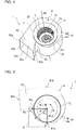
- Fig. 1 is a perspective view of the centrifugal fan 1 according to Embodiment 1 of the present disclosure.
- Fig. 2 is a schematic diagram of the centrifugal fan 1 according to Embodiment 1 of the present disclosure as viewed from an air inlet 5 side thereof.
- Fig. 2 is a schematic diagram illustrating a cross-section of the center portion of a scroll casing 4 in the axial direction of a below-described rotation shaft RS.
- a description will be given with reference to the cross-section of the center portion of the scroll casing 4 in the axial direction of the rotation shaft RS.
- a cross-section of another portion of the scroll casing 4 may be referred to.
- the configuration of the centrifugal fan 1 described below only needs to be present at least a part thereof in the axial direction of the rotation shaft RS, and may be present in the entire region thereof in the axial direction of the rotation shaft RS.
- a basic structure of the centrifugal fan 1 will be described with reference to Figs. 1 and 2 .
- the centrifugal fan 1 is a multi-blade centrifugal-type centrifugal fan 1 such as a sirocco fan or a turbofan, and includes a fan 2 configured to generate airflow, and the scroll casing 4 housing the fan 2.
- the fan 2 is configured to be driven by a motor or other devices (not illustrated) to rotate, and forcibly send air radially outward by a centrifugal force generated by the rotation.
- the fan 2 includes a disk-shaped main plate 2a and a plurality of blades 2d disposed at a peripheral edge portion 2a1 of the main plate 2a.
- the main plate 2a only needs to have a plate shape, and may have a shape (such as a polygonal shape) other than a disk shape.
- a shaft portion 2b to which the motor (not illustrated) is connected is disposed at the center of the main plate 2a.
- the fan 2 is formed in a cylindrical shape by the main plate 2a and the plurality of blades 2d, and has air inlets 2e, one at each end opposite to the main plate 2a in the axial direction of the rotation shaft RS of the fan 2.
- the air inlets 2e allow gas to enter the space surrounded by the main plate 2a and the plurality of blades 2d.
- the plurality of blades 2d are arranged circumferentially about the shaft portion 2b, and proximal ends thereof are fixed to the main plate 2a.
- the plurality of blades 2d are disposed on both sides of the main plate 2a in the axial direction of the rotation shaft RS of the shaft portion 2b.
- the plurality of blades 2d may be disposed on only one side of the main plate 2a in the axial direction of the rotation shaft RS of the shaft portion 2b.
- the blades 2d are spaced at regular intervals from each other at the peripheral edge portion 2a1 of the main plate 2a.
- Each blade 2d is formed in, for example, a curved rectangular plate shape, and is disposed in parallel to the radial direction or inclined at a predetermined angle with respect to the radial direction.
- the fan 2 is driven to rotate about the rotation shaft RS when the motor (not illustrated) is driven.
- gas outside the centrifugal fan 1 passes through the air inlets 5 formed in the scroll casing 4 and the air inlets 2e of the fan 2, and is suctioned into the space surrounded by the main plate 2a and the plurality of blades 2d.
- the air suctioned into the space surrounded by the main plate 2a and the plurality of blades 2d passes between the adjacent blades 2d, and is sent radially outward.
- each blade 2d is disposed upright to be substantially perpendicular to the main plate 2a.
- the configuration is not limited thereto.
- Each blade 2d may be inclined to the perpendicular direction of the main plate 2a.
- the scroll casing 4 houses the fan 2, and straightens the air blown out from the fan 2.
- the scroll casing 4 includes a scroll portion 41 and an outlet portion 42.
- the scroll portion 41 forms an air flow passage configured to convert a dynamic pressure of the airflow generated by the fan 2 to a static pressure.
- the scroll portion 41 includes side walls 4a each covering the fan 2 in the axial direction of the rotation shaft RS of the shaft portion 2b of the fan 2 and having the air inlet 5 configured to suction air, and a peripheral wall 4c surrounding the fan 2 in the radial direction of the rotation shaft RS of the shaft portion 2b of the fan 2.
- the scroll portion 41 further includes a tongue portion 43 disposed between the outlet portion 42 and an inner end 41a of the peripheral wall 4c to define a curved surface, and configured to guide the airflow generated by the fan 2 to an air outlet 42a via the scroll portion 41.
- the radial direction of the rotation shaft RS is a direction perpendicular to the rotation shaft RS.
- An inner space in the scroll portion 41 defined by the peripheral wall 4c and the side walls 4a is a space in which the air blown out from the fan 2 flows along the peripheral wall 4c.
- Each side wall 4a is disposed substantially perpendicular to the axial direction of the rotation shaft RS of the fan 2 to cover the fan 2.
- the air inlet 5 is formed in the side wall 4a of the scroll casing 4 to allow air to flow between the fan 2 and the outside of the scroll casing 4.
- the air inlet 5 is formed in a circular shape, and is disposed such that the center of the air inlet 5 substantially coincides with the center of the shaft portion 2b of the fan 2. With this configuration of the side wall 4a, the air in the vicinity of the air inlet 5 smoothly flows, and efficiently enters the fan 2 from the air inlet 5.
- the centrifugal fan 1 includes the scroll casing 4 of a double-inlet type that has the side walls 4a each having the air inlet 5, one on each side of the main plate 2a in the axial direction of the rotation shaft RS of the shaft portion 2b. That is, the centrifugal fan 1 includes the scroll casing 4 having two side walls 4a, and the side walls 4a are disposed to face each other. Note that the centrifugal fan 1 may include a scroll casing 4 of a single-inlet type that has the side wall 4a having the air inlet 5, only on one side of the main plate 2a in the axial direction of the rotation shaft RS of the shaft portion 2b. In this case, the scroll casing 4 of the centrifugal fan 1 has the side wall 4a having the air inlet 5, and a side wall (not illustrated) having no air inlet 5 and disposed to face the side wall 4a.
- the air inlet 5 formed in the side wall 4a is defined by a bell mouth 3.
- the bell mouth 3 straightens the flow of gas to be suctioned into the fan 2 to guide the gas into the air inlet 2e of the fan 2.
- the bell mouth 3 is formed such that its opening diameter gradually decreases from the outer side toward the inner side of the scroll casing 4.
- the peripheral wall 4c surrounds the fan 2 in the radial direction of the shaft portion 2b to define an inner peripheral surface facing the plurality of blades 2d.
- the peripheral wall 4c faces the air outlet side of the blades 2d of the fan 2.
- the peripheral wall 4c is disposed substantially parallel to the axial direction of the rotation shaft RS of the fan 2 to cover the fan 2. As illustrated in Fig. 2 , the peripheral wall 4c extends from the inner end 41a located at the boundary with the tongue portion 43 to an outer end 41b located at the boundary between the outlet portion 42 and the scroll portion 41 on the side far from the tongue portion 43 in a rotation direction R of the fan 2.
- the inner end 41a corresponds to an end on the upstream side of the airflow generated by the rotation of the fan 2
- the outer end 41b corresponds to an end on the downstream side of the airflow generated by the rotation of the fan 2, at the peripheral wall 4c forming a curved surface.
- the peripheral wall 4c has a width in the axial direction of the rotation shaft RS of the fan 2.
- the peripheral wall 4c is formed in a volute shape.
- the volute shape may be, for example, a volute shape based on a logarithm spiral, an Archimedean spiral, or an involute curve.
- the inner peripheral surface of the peripheral wall 4c forms a curved surface that is smoothly curved from the inner end 41a as a scroll start end of the volute shape to the outer end 41b as a scroll terminal end of the volute shape in the circumferential direction of the fan 2.
- the outlet portion 42 defines the air outlet 42a through which the airflow generated by the fan 2 and having passed through the scroll portion 41 is discharged.
- the outlet portion 42 is formed of a hollow pipe having a rectangular shape in a cross-section orthogonal to the direction of the airflow flowing along the peripheral wall 4c. As illustrated in Figs. 1 and 2 , the outlet portion 42 defines a flow passage that guides the air sent from the fan 2 and flowing though the clearance between the peripheral wall 4c and the fan 2 to discharge the air to the outside of the scroll casing 4.
- the outlet portion 42 includes an extension plate 42b, a diffuser plate 42c, a first side plate 42d, and a second side plate 42e.
- the extension plate 42b smoothly continues to the outer end 41b on the downstream side of the peripheral wall 4c, and is formed integrally with the peripheral wall 4c.
- the diffuser plate 42c is formed integrally with the tongue portion 43 of the scroll casing 4, and faces the extension plate 42b.
- the diffuser plate 42c is formed at a predetermined angle with respect to the extension plate 42b such that the cross-sectional area of the flow passage gradually increases in the direction of the airflow in the outlet portion 42.
- the first side plate 42d is formed integrally with the side wall 4a of the scroll casing 4
- the second side plate 42e is formed integrally with the side wall 4a on the opposite side of the scroll casing 4.
- the first side plate 42d and the second side plate 42e are formed between the extension plate 42b and the diffuser plate 42c.
- the outlet portion 42 has a flow passage with a rectangular cross-sectional shape defined by the extension plate 42b, the diffuser plate 42c, the first side plate 42d, and the second side plate 42e.
- the tongue portion 43 is formed between the diffuser plate 42c of the outlet portion 42 and the inner end 41a of the peripheral wall 4c in the scroll casing 4.
- the tongue portion 43 minimizes the air flowing from the scroll terminal end to the scroll start end of the volute-shaped flow passage.
- the tongue portion 43 is disposed on the upstream side of the air flow passage, and serves to separate between an airflow flowing in the rotation direction R of the fan 2 and an airflow flowing from the downstream of the air flow passage to the air outlet 42a.
- the tongue portion 43 is disposed at the boundary portion between the scroll portion 41 and the outlet portion 42, and is a protrusion expanding toward the inner side of the scroll casing 4.
- the tongue portion 43 extends in a direction parallel to the axial direction of the rotation shaft RS of the shaft portion 2b in the scroll casing 4.
- the tongue portion 43 is disposed between the end of the outlet portion 42 and the inner end 41a of the peripheral wall 4c to define a curved surface, and configured to guide the airflow generated by the fan 2 to the air outlet 42a via the scroll portion 41.
- the tongue portion 43 is formed to have a predetermined curvature radius, and the peripheral wall 4c is smoothly connected to the diffuser plate 42c via the tongue portion 43.
- the tongue portion 43 serves as a branching point of the flow passage of the air. That is, at the inlet port of the outlet portion 42, an airflow moving toward the air outlet 42a and an airflow flowing again to the upstream side from the tongue portion 43. Further, when the airflow passes through the scroll casing 4, its static pressure increases. Therefore, the airflow entering the outlet portion 42 has a pressure higher than the pressure in the scroll casing 4. Accordingly, the tongue portion 43 has a function for separating such different pressures, and guiding the air that is to enter the outlet portion 42 to each flow passage.
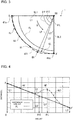
- Fig. 3 is an enlarged view of a part B of the centrifugal fan 1 of Fig. 2 .
- the peripheral wall 4c of the centrifugal fan 1 of Embodiment 1 is indicated by the long-dashed line for comparison with a below-described reference peripheral wall CL.
- the structure of the centrifugal fan 1 of Embodiment 1 will be described with reference to Figs. 2 and 3 .
- An outer peripheral portion FL illustrated in Figs. 2 and 3 is an outer peripheral portion of the fan 2.
- the outer peripheral portion FL is in the position of the edges of the blades 2d located at the outermost periphery of the fan 2 in plan view as viewed in the axial direction of the rotation shaft RS of the centrifugal fan 1.
- the distance between the outer peripheral portion FL and the rotation shaft RS is constant throughout. Note that the edges of the blades 2d refer to the radially outer edge of the fan 2.
- the reference peripheral wall CL illustrated in Fig. 3 represents a peripheral wall of a centrifugal fan of a comparative example.
- the reference peripheral wall CL is a virtual peripheral wall configured such that the peripheral wall 4c approaches the rotation shaft RS at a constant rate from the inner end 41a toward a below-described closest portion 41c.
- the closest portion 41c is a portion that is located between the inner end 41a and the outer end 41b of the reference peripheral wall CL and at which the distance between the reference peripheral wall CL and the rotation shaft RS is minimum.
- the closest portion 41c is a portion that is located between the inner end 41a and the outer end 41b of the reference peripheral wall CL and at which the distance between the reference peripheral wall CL and the outer peripheral portion FL of the fan 2 is minimum.
- a portion that is located between the inner end 41a and the outer end 41b of the peripheral wall 4c and at which the distance between the peripheral wall 4c of the scroll casing 4 and the rotation shaft RS is minimum is also defined as the closest portion 41c.
- the closest portion 41c is a portion that is located between the inner end 41a and the outer end 41b of the peripheral wall 4c and at which the distance between the peripheral wall 4c of the scroll casing 4 and the outer peripheral portion FL of the fan 2 is minimum.
- the centrifugal fan of the comparative example has a structure in which the closest portion 41c is shifted from the tongue portion 43 in the rotation direction R of the fan 2.
- the centrifugal fan 1 according to Embodiment 1 also has a structure in which the closest portion 41c is shifted from the tongue portion 43 in the rotation direction R of the fan 2. Note that although the closest portion 41c is formed in the position rotated by about 90 degrees from the inner end 41a in the circumferential direction of the rotation shaft RS in Figs. 2 and 3 , the position where the closest portion 41c is formed is not limited to the position rotated by about 90 degrees from the inner end 41a. The closest portion 41c only needs to be formed in a position between the inner end 41a and the outer end 41b.
- the closest portion 41c may be formed in the position rotated by about 180 degrees from the inner end 41a. It is particularly preferable that the closest portion 41c is formed near an air inlet of, for example, an indoor unit in which the centrifugal fan 1 is disposed. Note that the relationship between the closest portion 41c and an air inlet of an air-conditioning apparatus will be described below.
- a first reference line BL1 is a virtual line connecting the rotation shaft RS to the inner end 41a in a cross-section perpendicular to the rotation shaft RS.
- a second reference line BL2 is a virtual line connecting the rotation shaft RS to the closest portion 41c in the cross-section perpendicular to the rotation shaft RS.
- a distance L illustrated in Fig. 2 represents the distance between the rotation shaft RS and the peripheral wall 4c or the reference peripheral wall CL.
- a distance LP illustrated in Fig. 3 represents the distance between the rotation shaft RS and the peripheral wall 4c in the direction perpendicular to the rotation shaft RS.
- a distance LS represents the distance between the rotation shaft RS and the reference peripheral wall
- a distance L1 represents the distance between the rotation shaft RS and the inner end 41a of the peripheral wall of the centrifugal fan of the comparative example in the direction perpendicular to the rotation shaft RS.
- the distance L1 represents the length of the first reference line BL1.
- the distance L1 also represents the distance between the rotation shaft RS and the inner end 41a of the peripheral wall 4c in the direction perpendicular to the rotation shaft RS. That is, the inner ends 41a of the centrifugal fan of the comparative example and the centrifugal fan 1 according to Embodiment 1 are located in the same position in the circumferential direction and the radial direction of the fan 2.
- a distance L2 represents the distance between the rotation shaft RS and the closest portion 41c of the peripheral wall of the centrifugal fan of the comparative example in the direction perpendicular to the rotation shaft RS.
- the distance L2 represents the length of the second reference line BL2.
- the distance L2 also represents the distance between the rotation shaft RS and the closest portion 41c of the peripheral wall 4c in the direction perpendicular to the rotation shaft RS. That is, the closest portions 41c of the centrifugal fan of the comparative example and the centrifugal fan 1 according to Embodiment 1 are located in the same position in the circumferential direction and the radial direction of the fan 2.
- An angle ⁇ illustrated in Fig. 2 is an angle rotated from the first reference line BL1 in the rotation direction R of the fan 2, in a region between the first reference line BL1 connecting the rotation shaft RS to the inner end 41a and the second reference line BL2 connecting the rotation shaft RS to the closest portion 41c, in a cross-section perpendicular to the rotation shaft RS.
- An angle ⁇ P illustrated in Fig. 3 is an angle in the circumferential direction rotated from the inner end 41a to a measurement position of the distance LP about the rotation shaft RS, in plan view as viewed in the axial direction of the rotation shaft RS of the centrifugal fan 1.
- An angle ⁇ S is an angle in the circumferential direction rotated from the inner end 41a to a measurement position of the distance LS about the rotation shaft RS, in plan view as viewed in the axial direction of the rotation shaft RS of the centrifugal fan of the comparative example.
- An angle ⁇ L is an angle in the circumferential direction rotated from the inner end 41a to the position of the closest portion 41c about the rotation shaft RS, in plan view as viewed in the axial direction of the rotation shaft RS of the centrifugal fan 1. Note that although the angle ⁇ L is set to about 90 degrees in Figs. 2 and 3 , the angle ⁇ L is not limited to about 90 degrees. The angle ⁇ L may be any angle between the inner end 41a to the outer end 41b. For example, the angle ⁇ L may be about 180 degrees.
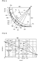
- Fig. 4 is a graph illustrating a relationship between the angle ⁇ and the distance L in each of the centrifugal fan 1 of Fig. 3 and the centrifugal fan of the comparative example. The structure of the centrifugal fan 1 will be described in greater detail with reference to Figs. 3 and 4 .
- a reference line A-A' illustrated in Fig. 4 represents a relationship between the angle ⁇ of the reference peripheral wall CL and the distance LS in the region from the inner end 41a to the closest portion 41c.
- the reference peripheral wall CL is formed such that the distance LS decreases at a constant rate as the angle ⁇ increases from the inner end 41a toward the closest portion 41c.
- the centrifugal fan of the comparative example is formed such that the reference peripheral wall CL approaches the rotation shaft RS at a predetermined rate from the inner end 41a toward the closest portion 41c. That is, the centrifugal fan of the comparative example is formed such that a gas flow passage narrows at a constant rate from the inner end 41a toward the closest portion 41c.
- a curved line PL indicated by the long-dashed line in Fig. 4 represents a relationship between the angle ⁇ P of the peripheral wall 4c and the distance LP in the region from the inner end 41a to the closest portion 41c.
- the peripheral wall 4c includes an expanded portion 4c1 between the inner end 41a and the closest portion 41c.
- the expanded portion 4c1 is a portion of the peripheral wall 4c at which the distance LP between the rotation shaft RS and the peripheral wall 4c is greater than or equal to the distance LS between the rotation shaft RS and the reference peripheral wall CL.
- the expanded portion 4c1 is formed such that a part of the peripheral wall 4c expands in the radial direction of the fan 2.
- the expanded portion 4c1 is a portion that is located on the inner end 41a side of the closest portion 41c and at which the distance between the peripheral wall 4c and the rotation shaft RS is increased.
- the expanded portion 4c1 is a portion that is located on the inner end 41a side of the closest portion 41c and at which the distance between the peripheral wall 4c and the outer peripheral portion FL of the fan 2 is increased. Note that as illustrated in Fig. 4 , the distance between the peripheral wall 4c and the rotation shaft RS at the expanded portion 4c1 is less than the distance between the peripheral wall 4c and the rotation shaft RS at the inner end 41a.
- the peripheral wall 4c includes a narrowed portion 4d at which the distance between the peripheral wall 4c and the rotation shaft RS decreases from the inner end 41a toward the closest portion 41c in the rotation direction R of the fan 2.
- the narrowed portion 4d is a portion of the peripheral wall 4c at which the distance between the peripheral wall 4c and the outer peripheral portion FL of the fan 2 decreases from the inner end 41a toward the closest portion 41c in the rotation direction R of the fan 2.
- the narrowed portion 4d is formed to extend from the inner end 41a to the expanded portion 4c1 in the rotation direction R of the fan 2 such that the distance LP decreases at a constant rate as the angle ⁇ increases from the inner end 41a toward the closest portion 41c.
- the rate at which the distance LP decreases as the angle ⁇ increases is equal to the rate at which the distance LS decreases as the angle ⁇ increases. That is, the peripheral wall 4c from the inner end 41a to the expanded portion 4c1 is formed such that the curved line PL has the same inclination as the reference line A-A'.
- the peripheral wall 4c includes a first inflection portion U1 and a second inflection portion M1 at the expanded portion 4c1.
- the first inflection portion U1 is a minimum point of the curved line PL at the expanded portion 4c1
- the second inflection portion M1 is a maximum point of the curved line PL at the expanded portion 4c1.
- the first inflection portion U1 is a boundary portion between a part where the peripheral wall 4c approaches the rotation shaft RS and a part where the peripheral wall 4c separates from the rotation shaft RS, from the inner end 41a toward the closest portion 41c.
- the first inflection portion U1 is a boundary portion between a part where the peripheral wall 4c approaches the outer peripheral portion FL of the fan 2 and a part where the peripheral wall 4c separates from the outer peripheral portion FL of the fan 2, from the inner end 41a toward the closest portion 41c.
- the second inflection portion M1 is a boundary portion between the part where the peripheral wall 4c separates from the rotation shaft RS and a part where the peripheral wall 4c approaches the rotation shaft RS, from the inner end 41a toward the closest portion 41c.
- the second inflection portion M1 is a boundary portion of the part where the peripheral wall 4c separates from the outer peripheral portion FL of the fan 2 and a part where the peripheral wall 4c approaches the outer peripheral portion FL of the fan 2, from the inner end 41a toward the closest portion 41c. That is, as illustrated in Fig. 4 , in terms of the relationship between the angle ⁇ P and the distance LP, the expanded portion 4c1 of the peripheral wall 4c is formed to have a downwardly protruding curved line and an upwardly protruding curved line in the direction from the inner end 41a toward the closest portion 41c.
- the peripheral wall 4c is configured to gradually separate from the rotation shaft RS, from the first inflection portion U1 to the second inflection portion M1 in the rotation direction R. That is, the peripheral wall 4c is configured to gradually separate from the outer peripheral portion FL of the fan 2, from the first inflection portion U1 to the second inflection portion M1 in the rotation direction R. Accordingly, in the centrifugal fan 1, the gas flow passage between the first inflection portion U1 and the second inflection portion M1 widens in the rotation direction R.
- the distance between the outer peripheral portion FL of the fan 2 and the rotation shaft RS is constant throughout. Further, the peripheral wall 4c from the inner end 41a to the expanded portion 4c1 in the rotation direction R of the fan 2 is formed such that the distance LP decreases at a constant rate as the angle ⁇ increases from the inner end 41a toward the closest portion 41c. Therefore, in the centrifugal fan 1, the distance between the peripheral wall 4c and the blades 2d gradually decreases from the inner end 41a toward the expanded portion 4c1. Further, the centrifugal fan 1 includes the expanded portion 4c1.
- the distance between the peripheral wall 4c and the blades 2d at the expanded portion 4c1 is increased, compared to the distance between the peripheral wall 4c and the blades 2d in the region from the inner end 41a to the expanded portion 4c1.
- the tongue portion 43 is formed on the upstream side of the airflow with respect to the inner end 41a, and the inner end 41a is formed at the downstream end of the tongue portion 43.
- the gas flow passage formed between the peripheral wall 4c and the outer peripheral portion FL of the fan 2 is gradually narrowed at the narrowed portion 4d from the inner end 41a toward the closest portion 41c, and then the gas flow passage is widened at the expanded portion 4c1.
- the air suctioned into the scroll casing 4 is suctioned into the scroll casing 4 through the air inlet 5.
- the air suctioned into the scroll casing 4 is guided by the bell mouth 3 and suctioned into the fan 2.
- the air suctioned into the fan 2 is turned into an airflow with a dynamic pressure and a static pressure applied thereto, and is blown out to the radially outer side of the fan 2.
- the dynamic pressure is converted into static pressure while the airflow is guided between the inner side of the peripheral wall 4c and the blades 2d in the scroll portion 41.
- the airflow passes through the scroll portion 41, and then is blown out to the outside of the scroll casing 4 from the air outlet 42a formed in the outlet portion 42.
- the centrifugal fan 1 includes the narrowed portion 4d at which the distance between the peripheral wall 4c and the rotation shaft RS decreases from the inner end 41a toward the closest portion 41c in the rotation direction R of the fan 2.
- the centrifugal fan further includes the expanded portion 4c1 that is formed between the narrowed portion 4d and the closest portion 41c and at which the distance between the peripheral wall 4c and the rotation shaft RS is increased. Therefore, in the centrifugal fan 1, the distance between the peripheral wall 4c and the outer peripheral portion FL of the fan 2 is gradually reduced from the tongue portion 43 toward the closest portion 41c, and then the distance between the peripheral wall 4c and the outer peripheral portion FL of the fan 2 is increased in front of the closest portion 41c.
- the centrifugal fan 1 since the distance between the peripheral wall 4c and the outer peripheral portion FL of the fan 2 is increased in front of the closest portion 41c, the air volume is secured. Further, as the gas of the secured volume passes through the closest portion 41c, the velocity of the gas is increased. Accordingly, the centrifugal fan 1 can effectively increase the pressure in the scroll portion 41.
- the gas flow passage formed between the peripheral wall 4c and the outer peripheral portion FL of the fan 2 is gradually narrowed at the narrowed portion 4d from the inner end 41a toward the closest portion 41c, and then the flow passage is widened at the expanded portion 4c1.
- the centrifugal fan 1 since the distance between the peripheral wall 4c and the outer peripheral portion FL of the fan 2 is increased in front of the closest portion 41c, the air volume is secured. Further, as the gas of the secured volume passes through the closest portion 41c, the velocity of the gas is increased. Accordingly, the centrifugal fan 1 can effectively increase the pressure in the scroll portion 41.
- the expanded portion 4c1 expands in the radial direction of the fan 2. Since the distance between the peripheral wall 4c and the outer peripheral portion FL of the fan 2 is increased in front of the closest portion 41c, the centrifugal fan 1 can secure the air volume. Further, as the gas of the secured volume passes through the closest portion 41c, the velocity of the gas is increased. Accordingly, the centrifugal fan 1 can effectively increase the pressure in the scroll portion 41.
- the peripheral wall 4c includes the first inflection portion U1 defining a boundary portion between a part where the peripheral wall 4c approaches the rotation shaft RS and a part where the peripheral wall 4c separates from the rotation shaft RS, and the second inflection portion M1 defining a boundary portion between the part where the peripheral wall 4c separates from the rotation shaft RS and a part where the peripheral wall 4c approaches the rotation shaft RS.
- the centrifugal fan 1 since the distance between the peripheral wall 4c and the outer peripheral portion FL of the fan 2 is increased in front of the closest portion 41c, the air volume is secured. Further, as the gas of the secured volume passes through the closest portion 41c, the velocity of the gas is increased. Accordingly, the centrifugal fan 1 can effectively increase the pressure in the scroll portion 41.
- the peripheral wall 4c is configured to gradually separate from the rotation shaft RS, from the first inflection portion U1 to the second inflection portion M1. Since the distance between the peripheral wall 4c and the outer peripheral portion FL of the fan 2 is increased in front of the closest portion 41c, the centrifugal fan 1 can secure the air volume. Further, as the gas of the secured volume passes through the closest portion 41c, the velocity of the gas is increased. Accordingly, the centrifugal fan 1 can effectively increase the pressure in the scroll portion 41.
- the distance between the peripheral wall 4c and the rotation shaft RS at the expanded portion 4c1 is less than the distance between the peripheral wall 4c and the rotation shaft RS at the inner end 41a. Therefore, the centrifugal fan 1 can maintain the velocity of the gas in the flow passage increased at the narrowed portion 4d to some extent, and can reduce separation of the gas.
- the centrifugal fan 1 can reduce a sudden pressure difference in the tongue portion 43, and reduce the noise level.
- Fig. 5 is an enlarged view of modified examples of the centrifugal fan 1 according to Embodiment 1 of the present disclosure.
- Fig. 6 is a graph illustrating a relationship between the angle ⁇ and the distance L in each of the modified examples of the centrifugal fan 1 according to Embodiment 1 of the present disclosure and the centrifugal fan of the comparative example.
- the centrifugal fans 1A, 1B, and 1C as modified examples of the centrifugal fan 1 will be described with reference to Figs. 5 and 6 . Note that parts having the same configurations as those of the centrifugal fan 1 in Figs. 1 to 4 are denoted by the same reference numerals, and a description thereof will be omitted.
- a distance L11 is the distance between a rotation shaft RS of the centrifugal fan 1A and a peripheral wall 4ca in the direction perpendicular to the rotation shaft RS of the centrifugal fan 1A.
- a distance L12 is the distance between a rotation shaft RS of the centrifugal fan 1B and a peripheral wall 4cb in the direction perpendicular to the rotation shaft RS of the centrifugal fan 1B.
- a distance L13 is the distance between a rotation shaft RS of the centrifugal fan 1C and a peripheral wall 4cc in the direction perpendicular to the rotation shaft RS of the centrifugal fan 1C.
- each of the peripheral wall 4ca of the centrifugal fan 1A, the peripheral wall 4cb of the centrifugal fan 1B, and the peripheral wall 4cc of the centrifugal fan 1A is a wall portion corresponding to the peripheral wall 4c of the centrifugal fan 1.
- the angle ⁇ P described above represents the angle in the circumferential direction rotated from the inner end 41a to a measurement position of the distance L11 about the rotation shaft RS when the centrifugal fan 1A is viewed in plan view in the axial direction of the rotation shaft RS.
- the angle ⁇ P described above also represents the angle rotated about the rotation shaft RS from the inner end 41a to a measurement position of the distance L12 in the circumferential direction when the centrifugal fan 1B is viewed in plan view in the axial direction of the rotation shaft RS.
- the angle ⁇ P described above also represents the angle rotated about the rotation shaft RS from the inner end 41a to a measurement position of the distance L13 in the circumferential direction when the centrifugal fan 1C is viewed in plan view in the axial direction of the rotation shaft RS.
- a curved line PL1 indicated by the long-dashed line in Fig. 6 represents a relationship between the angle ⁇ P and the distance L11 in the region from the inner end 41a to the closest portion 41c.
- a curved line PL2 indicated by the one-dot chain line in Fig. 6 represents a relationship between the angle ⁇ P and the distance L12 in the region from the inner end 41a to the closest portion 41c.
- a curved line PL3 indicated by the short-dashed line in Fig. 6 represents a relationship between the angle ⁇ P and the distance L13 in the region from the inner end 41a to the closest portion 41c.
- each of the peripheral walls 4ca, 4cb, and 4cc includes an expanded portion 4c1 between the inner end 41a and the closest portion 41c.
- the peripheral wall 4ca from the inner end 41a to the expanded portion 4c1 in the rotation direction R of the fan 2 includes a narrowed portion 4d1 at which the distance L11 decreases as the angle ⁇ increases from the inner end 41a toward the closest portion 41c.
- the peripheral wall 4cb from the inner end 41a to the expanded portion 4c1 in the rotation direction R of the fan 2 includes a narrowed portion 4d2 at which the distance L12 decreases at a constant rate as the angle ⁇ increases from the inner end 41a toward the closest portion 41c.
- the peripheral wall 4cc from the inner end 41a to the expanded portion 4c1 in the rotation direction R of the fan 2 includes a narrowed portion 4d3 at which the distance L13 decreases at a constant rate as the angle ⁇ increases from the inner end 41a toward the closest portion 41c.
- the peripheral wall 4ca includes a first inflection portion PU1 and a second inflection portion PM1.
- the first inflection portion PU1 is a minimum point of the curved line PL1
- the second inflection portion PM1 is a maximum point of the curved line PL1. That is, as illustrated in Fig. 6 , in terms of the relationship between the angle ⁇ P and the distance L11, the peripheral wall 4ca is formed to have a downwardly protruding curved line and an upwardly protruding curved line in the direction from the inner end 41a toward the closest portion 41c.
- peripheral wall 4ca is configured such that a wall portion between the first inflection portion PU1 and the second inflection portion PM1 separates from the outer peripheral portion FL of the fan 2 in the rotation direction R. Accordingly, the peripheral wall 4ca is configured such that the gas flow passage between the first inflection portion PU1 and the second inflection portion PM1 widens in the rotation direction R.
- the peripheral wall 4ca is configured such that the first inflection portion PU1 is located below the reference line A-A'. That is, the peripheral wall 4ca is configured such that a wall portion from the inner end 41a to the first inflection portion U1 approaches the outer peripheral portion FL of the fan 2 in the rotation direction R. Accordingly, the peripheral wall 4ca is configured such that the gas flow passage between the inner end 41a and the first inflection portion U1 narrows in the rotation direction R. As a result, the centrifugal fan 1A can reduce a sudden pressure difference in the tongue portion 43, and further reduce the noise level.
- the peripheral wall 4ca is configured such that the gas flow passage between the inner end 41a and the first inflection portion U1 narrows, and then the gas flow passage widens at the expanded portion 4c1, in the rotation direction R. Accordingly, the centrifugal fan 1A can accelerate the gas between the inner end 41a and the first inflection portion U1 where the gas flow passage narrows, increase the air volume at the expanded portion 4c1, and increase the pressure at the closest portion 41c. With the configuration and operation described above, the centrifugal fan 1A can even out the air velocity around the closest portion 41c, and balance the pressure.
- the peripheral wall 4cb includes a first inflection portion PU2 and a second inflection portion PM2 at the expanded portion 4c1.
- the first inflection portion PU2 is a minimum point of the curved line PL2 at the expanded portion 4c1
- the second inflection portion PM2 is a maximum point of the curved line PL2 at the expanded portion 4c1. That is, as illustrated in Fig.
- the peripheral wall 4cb is configured such that a wall portion from the inner end 41a to a first inflection portion U2 approaches the outer peripheral portion FL of the fan 2 in the rotation direction R. Accordingly, the peripheral wall 4cb is configured such that the gas flow passage between the inner end 41a and the first inflection portion U2 narrows in the rotation direction R. However, as illustrated in Fig. 6 , the peripheral wall 4cb is configured such that the first inflection portion PU2 is located above the reference line A-A'. Accordingly, in the centrifugal fan 1B, the rate at which the peripheral wall 4cb approaches the outer peripheral portion FL of the fan 2 is less than the rate at which the reference peripheral wall CL approaches the outer peripheral portion FL of the fan 2, in the rotation direction R. Compared to the centrifugal fan of the comparative example, the centrifugal fan 1B makes it possible to increase the capacity of the gas flow passage between the peripheral wall 4cb and the outer peripheral portion FL of the fan 2, and increase the suction air volume.
- the peripheral wall 4cc includes a first inflection portion PU3 and a second inflection portion PM3 at the expanded portion 4c1.
- the first inflection portion PU3 is a minimum point of the curved line PL3 at the expanded portion 4c1
- the second inflection portion PM3 is a maximum point of the curved line PL3 at the expanded portion 4c1. That is, as illustrated in Fig.
- the expanded portion 4c1 of the peripheral wall 4cc is formed to have a downwardly protruding curved line and an upwardly protruding curved line in the direction from the inner end 41a toward the closest portion 41c.
- the peripheral wall 4cc is configured such that a wall portion between the first inflection portion PU3 and the second inflection portion PM3 separates from the outer peripheral portion FL of the fan 2 in the rotation direction R. Accordingly, the peripheral wall 4cc is configured such that the gas flow passage between the first inflection portion PU3 and the second inflection portion PM3 widens in the rotation direction R.
- the peripheral wall 4cc is configured such that a wall portion from the inner end 41a to the first inflection portion U1 approaches the outer peripheral portion FL of the fan 2 in the rotation direction R. Accordingly, the peripheral wall 4cc is configured such that the gas flow passage between the inner end 41a and the first inflection portion U3 narrows in the rotation direction R. However, as illustrated in Fig. 6 , the peripheral wall 4cc is configured such that the first inflection portion PU3 is located above the reference line A-A'. Accordingly, in the centrifugal fan 1C, the rate at which the peripheral wall 4cc approaches the outer peripheral portion FL of the fan 2 is less than the rate at which the reference peripheral wall CL approaches the outer peripheral portion FL of the fan 2, in the rotation direction R.
- the centrifugal fan 1C compared to the centrifugal fan of the comparative example, the capacity of the gas flow passage between the peripheral wall 4cc and the outer peripheral portion FL of the fan 2 is increased, so that the suction air volume can be increased. Further, the peripheral wall 4cc is configured such that the first inflection portion PU3 is closer to the inner end 41a than the first inflection portion PU2. Therefore, the centrifugal fan 1C has the expanded portion 4c1 greater than that of the centrifugal fan 1B.
- the centrifugal fan 1C compared to the centrifugal fan 1B, the capacity of the gas flow passage between the peripheral wall 4cc and the outer peripheral portion FL of the fan 2 is increased, so that the suction air volume can be increased.
- the centrifugal fan 1 is preferably configured such that the curved line PL is located below a point A in Fig. 4 . That is, the centrifugal fan 1 preferably includes the peripheral wall 4c formed such that the distance between the peripheral wall 4c and the rotation shaft RS is less than or equal to a distance L1 between the rotation shaft RS and the peripheral wall 4c at the inner end 41a. Accordingly, in the centrifugal fan 1, the expanded portion 4c1 also preferably includes the peripheral wall 4c formed such that the distance between the peripheral wall 4c and the rotation shaft RS is less than or equal to the distance L1 between the rotation shaft RS and the peripheral wall 4c at the inner end 41a.
- the centrifugal fan 1A preferably includes the peripheral wall 4ca formed such that the distance between the peripheral wall 4ca and the rotation shaft RS is less than or equal to the distance L1 between the rotation shaft RS and the peripheral wall 4ca at the inner end 41a.
- the centrifugal fan 1B preferably includes the peripheral wall 4cb formed such that the distance between the peripheral wall 4cb and the rotation shaft RS is less than or equal to the distance L1 between the rotation shaft RS and the peripheral wall 4cb at the inner end 41a.
- the centrifugal fan 1C preferably includes the peripheral wall 4cc formed such that the distance between the peripheral wall 4cc and the rotation shaft RS is less than or equal to the distance L1 between the rotation shaft RS and the peripheral wall 4cc at the inner end 41a.
- the centrifugal fans 1, 1A, 1B, and 1C can accelerate the gas in the flow passage, and reduce separation of the gas.
- Fig. 7 is a partially enlarged view of the centrifugal fan 1D according to Embodiment 2 of the present disclosure.
- Fig. 8 is a graph illustrating a relationship between the angle ⁇ and the distance L in each of the centrifugal fan 1D of Fig. 7 and the centrifugal fan of the comparative example. Note that parts having the same configurations as those of the centrifugal fan 1 and the other centrifugal fans in Figs. 1 to 6 are denoted by the same reference numerals, and a description thereof will be omitted.
- the centrifugal fan 1D of Embodiment 2 differs from the centrifugal fan 1 of Embodiment 1 in the shape of the peripheral wall 4c. Accordingly, the configuration of the peripheral wall 4c of the centrifugal fan 1D of Embodiment 2 will mainly be described with reference to Figs. 7 and 8 .
- a curved line TL indicated by the long-dashed line in Fig. 8 represents a relationship between the angle ⁇ P and the distance LP in the region from the inner end 41a to the closest portion 41c.
- the peripheral wall 4c includes an expanded portion 4c2 between the inner end 41a and the closest portion 41c.
- the expanded portion 4c2 is a portion of the peripheral wall 4c at which the distance LP between the rotation shaft RS and the peripheral wall 4c is greater than or equal to the distance LS between the rotation shaft RS and the reference peripheral wall CL.
- the expanded portion 4c2 is formed such that a part of the peripheral wall 4c expands in the radial direction of the fan 2.
- the expanded portion 4c2 is a portion that is located on the inner end 41a side of the closest portion 41c and at which the distance between the peripheral wall 4c and the rotation shaft RS is increased.
- the expanded portion 4c2 is a portion that is located on the inner end 41a side of the closest portion 41c and at which the distance between the peripheral wall 4c and the outer peripheral portion FL of the fan 2 is increased.
- the peripheral wall 4c includes a narrowed portion 4d at which the distance between the peripheral wall 4c and the rotation shaft RS decreases from the inner end 41a toward the closest portion 41c in the rotation direction R of the fan 2.
- the narrowed portion 4d is a portion of the peripheral wall 4c at which the distance between the peripheral wall 4c and the outer peripheral portion FL of the fan 2 decreases from the inner end 41a toward the closest portion 41c in the rotation direction R of the fan 2.
- the narrowed portion 4d is formed to extend from the inner end 41a to the expanded portion 4c1 in the rotation direction R of the fan 2 such that the distance LP decreases at a constant rate as the angle ⁇ increases from the inner end 41a toward the closest portion 41c.
- the rate at which the distance LP decreases as the angle ⁇ increases is equal to the rate at which the distance LS decreases as the angle ⁇ increases. That is, the peripheral wall 4c from the inner end 41a to the expanded portion 4c1 is formed such that the curved line TL has the same inclination as the reference line A-A'.
- the peripheral wall 4c includes a first inflection portion J1 and a second inflection portion K1 at the expanded portion 4c1.
- the first inflection portion J1 is a boundary portion between a part where the peripheral wall 4c approaches the rotation shaft RS and a part where the distance between the peripheral wall 4c and the rotation shaft RS is constant, from the inner end 41a toward the closest portion 41c.
- the first inflection portion J1 is a boundary portion between a part where the peripheral wall 4c approaches the outer peripheral portion FL of the fan 2 and a part where the distance between the peripheral wall 4c and the outer peripheral portion FL of the fan 2 is constant, from the inner end 41a toward the closest portion 41c.
- the second inflection portion K1 is a boundary portion between the part where the distance between the peripheral wall 4c and the rotation shaft RS is constant and a part where the peripheral wall 4c approaches the rotation shaft RS, from the inner end 41a toward the closest portion 41c.
- the second inflection portion K1 is a boundary portion of the part where the distance between the peripheral wall 4c and the outer peripheral portion FL of the fan 2 is constant and a part where the peripheral wall 4c approaches the outer peripheral portion FL of the fan 2, from the inner end 41a toward the closest portion 41c.
- the peripheral wall 4c includes a constant distance portion 4c3 defining the peripheral wall 4c between the first inflection portion J1 and the second inflection portion K1.
- the constant distance portion 4c3 is a portion formed between the narrowed portion 4d and the closest portion 41c and at which the distance between the peripheral wall 4c and the rotation shaft RS is constant.
- the constant distance portion 4c3 is a portion formed between the narrowed portion 4d and the closest portion 41c and at which the distance between the peripheral wall 4c and the outer peripheral portion FL of the fan 2 is constant.
- the peripheral wall 4c is configured such that the distance LP decreases as the angle ⁇ increases from the second inflection portion K1 toward the closest portion 41c in the rotation direction R of the fan 2.
- the distance between the outer peripheral portion FL of the fan 2 and the rotation shaft RS is constant throughout. Further, the peripheral wall 4c from the inner end 41a to the expanded portion 4c1 in the rotation direction R of the fan 2 is formed such that the distance LP decreases at a constant rate as the angle ⁇ increases from the inner end 41a toward the closest portion 41c. Therefore, in the centrifugal fan 1D, the distance between the peripheral wall 4c and the outer peripheral portion FL of the fan 2 gradually decreases from the inner end 41a toward the expanded portion 4c1. Further, the centrifugal fan 1D includes the expanded portion 4c1.
- the distance between the peripheral wall 4c and the blades 2d at the expanded portion 4c1 is greater than the distance between the peripheral wall 4c and the outer peripheral portion FL of the fan 2 in the region from the inner end 41a to the expanded portion 4c1.
- the peripheral wall 4c includes the constant distance portion 4c3 at which the distance between the rotation shaft RS and the peripheral wall 4c is constant at the expanded portion 4c2.
- the gas flow passage formed between the peripheral wall 4c and the outer peripheral portion FL of the fan 2 is gradually narrowed at the narrowed portion 4d from the inner end 41a toward the closest portion 41c, and then the flow passage widened at the expanded portion 4c2.
- the centrifugal fan 1D includes the constant distance portion 4c3 at the peripheral wall 4c where the distance between the rotation shaft RS and the peripheral wall 4c is constant.
- the centrifugal fan 1D includes the constant distance portion 4c3 at the peripheral wall 4c where the distance between the rotation shaft RS and the peripheral wall 4c is constant. Since the centrifugal fan 1D includes the constant distance portion 4c3, the distance between the rotation shaft RS and the peripheral wall 4c is constant, so that the variation in air velocity can be reduced. Therefore, the centrifugal fan 1D can reduce variation in wall surface pressure at the constant distance portion 4c3, and reduce the noise level.
- the constant distance portion 4c3 is formed between the first inflection portion J1 and the second inflection portion K1. Since the centrifugal fan 1D includes the constant distance portion 4c3, the distance between the rotation shaft RS and the peripheral wall 4c is constant, so that the variation in air velocity can be reduced. Therefore, the centrifugal fan 1D can reduce variation in wall surface pressure in the constant distance portion 4c3, and reduce the noise level.
- the centrifugal fan 1D the distance between the peripheral wall 4c and the outer peripheral portion FL of the fan 2 is gradually reduced from the tongue portion 43 toward the closest portion 41c, and then the distance between the peripheral wall 4c and the outer peripheral portion FL of the fan 2 is increased in front of the closest portion 41c.
- the centrifugal fan 1D since the distance between the peripheral wall 4c and the outer peripheral portion FL of the fan 2 is increased in front of the closest portion 41c, the air volume is secured. Further, as the gas of the secured volume passes through the closest portion 41c, the velocity of the gas is increased. Accordingly, the centrifugal fan 1 can effectively increase the pressure in the scroll portion 41.
- the centrifugal fan 1D can reduce a sudden pressure difference in the tongue portion 43, and reduce the noise level.
- Fig. 9 is an enlarged view of modified examples of the centrifugal fan 1D according to Embodiment 2 of the present disclosure.
- Fig. 10 is a graph illustrating a relationship between the angle ⁇ and the distance L in each of the modified examples of the centrifugal fan 1D according to Embodiment 2 of the present disclosure and the centrifugal fan of the comparative example.
- the centrifugal fans 1E, 1F, and 1G as modified examples of the centrifugal fan 1D will be described with reference to Figs. 9 and 10 . Note that parts having the same configurations as those of the centrifugal fan 1 and other centrifugal fans in Figs. 1 to 8 are denoted by the same reference numerals, and a description thereof will be omitted.
- a distance L21 is the distance between a rotation shaft RS of the centrifugal fan 1E and a peripheral wall 4ce in the direction perpendicular to the rotation shaft RS of the centrifugal fan 1E.
- a distance L22 is the distance between a rotation shaft RS of the centrifugal fan 1F and a peripheral wall 4cf in the direction perpendicular to the rotation shaft RS of the centrifugal fan 1F.
- a distance L23 is the distance between a rotation shaft RS of the centrifugal fan 1G and a peripheral wall 4cg in the direction perpendicular to the rotation shaft RS of the centrifugal fan 1G.
- each of the peripheral wall 4ce of the centrifugal fan 1E, the peripheral wall 4cf of the centrifugal fan 1F, and the peripheral wall 4cg of the centrifugal fan 1G is a wall portion corresponding to the peripheral wall 4c of the centrifugal fan 1D.
- the angle ⁇ P described above represents the angle in the circumferential direction rotated from the inner end 41a to a measurement position of the distance L21 about the rotation shaft RS when the centrifugal fan 1E is viewed in plan view in the axial direction of the rotation shaft RS.
- the angle ⁇ P described above also represents the angle in the circumferential direction rotated from the inner end 41a to a measurement position of the distance L22 about the rotation shaft RS when the centrifugal fan 1F is viewed in plan view in the axial direction of the rotation shaft RS.
- the angle ⁇ P described above also represents the angle in the circumferential direction rotated from the inner end 41a to a measurement position of the distance L23 about the rotation shaft RS when the centrifugal fan 1G is viewed in plan view in the axial direction of the rotation shaft RS.
- a curved line TL1 indicated by the long-dashed line in Fig. 10 represents a relationship between the angle ⁇ P and the distance L21 in the region from the inner end 41a to the closest portion 41c.
- a curved line TL2 indicated by the one-dot chain line in Fig. 10 represents a relationship between the angle ⁇ P and the distance L22 in the region from the inner end 41a to the closest portion 41c.
- a curved line TL3 indicated by the short-dashed line in Fig. 10 represents a relationship between the angle ⁇ P and the distance L23 in the region from the inner end 41a to the closest portion 41c.
- each of the peripheral walls 4ce, 4cf, and 4cg includes an expanded portion 4c2 between the inner end 41a and the closest portion 41c.
- the peripheral wall 4ce from the inner end 41a to the expanded portion 4c2 in the rotation direction R of the fan 2 includes a narrowed portion 4d4 at which the distance L21 decreases as the angle ⁇ increases from the inner end 41a toward the closest portion 41c.
- the peripheral wall 4cf from the inner end 41a to the expanded portion 4c2 in the rotation direction R of the fan 2 includes a narrowed portion 4d5 at which the distance L22 decreases at a constant rate as the angle ⁇ increases from the inner end 41a toward the closest portion 41c.
- the peripheral wall 4cg from the inner end 41a to the expanded portion 4c2 in the rotation direction R of the fan 2 includes a narrowed portion 4d6 at which the distance L23 decreases at a constant rate as the angle ⁇ increases from the inner end 41a toward the closest portion 41c.
- the peripheral wall 4ce includes a first inflection portion TJ1 and a second inflection portion TK1.
- the peripheral wall 4ce includes a constant distance portion 4c4 defining the peripheral wall 4ce between the first inflection portion TJ1 and the second inflection portion TK1.
- the constant distance portion 4c4 is a portion at which the distance between the rotation shaft RS and the peripheral wall 4ce is constant.
- the constant distance portion 4c4 is a portion at which the distance between the peripheral wall 4ce and the outer peripheral portion FL of the fan 2 is constant.
- the peripheral wall 4ce is configured such that the distance L21 decreases as the angle ⁇ increases from the second inflection portion TK1 toward the closest portion 41c.
- the peripheral wall 4cf includes a first inflection portion TJ2 and a second inflection portion TK2.
- the peripheral wall 4cf includes a constant distance portion 4c5 defining the peripheral wall 4cf between the first inflection portion TJ2 and the second inflection portion TK2.
- the constant distance portion 4c5 is a portion at which the distance between the rotation shaft RS and the peripheral wall 4cf is constant.
- the constant distance portion 4c5 is a portion at which the distance between the peripheral wall 4cf and the outer peripheral portion FL of the fan 2 is constant.
- the peripheral wall 4cf is configured such that the distance 22 decreases as the angle ⁇ increases from the second inflection portion TK2 toward the closest portion 41c.
- the peripheral wall 4cg includes a first inflection portion TJ3 and a second inflection portion TK3.
- the peripheral wall 4cg includes a constant distance portion 4c6 defining the peripheral wall 4cg between the first inflection portion TJ3 and the second inflection portion TK3.
- the constant distance portion 4c6 is a portion at which the distance between the rotation shaft RS and the peripheral wall 4cg is constant.
- the constant distance portion 4c6 is a portion at which the distance between the peripheral wall 4cg and the outer peripheral portion FL of the fan 2 is constant.
- the peripheral wall 4cg is configured such that the distance L23 decreases as the angle ⁇ increases from the second inflection portion TK3 toward the closest portion 41c.
- the constant distance portion 4c4 of the centrifugal fan 1E, the constant distance portion 4c5 of the centrifugal fan 1F, and the constant distance portion 4c6 of the centrifugal fan 1G differ from each other in length. That is, when the constant distance portion 4c3 is formed to have a length appropriate for the centrifugal fan 1D, the centrifugal fan 1D can reduce the variation in wall surface pressure, and reduce the noise level.
- Fig. 11 is a schematic diagram of the centrifugal fan 1H according to Embodiment 3 of the present disclosure as viewed from an air inlet side thereof.
- Fig. 12 is an enlarged view of a part B2 of the centrifugal fan 1H of Fig. 11 .
- Fig. 13 is a cross-sectional view taken along line B-B of Fig. 12 . Note that parts having the same configurations as those of the centrifugal fan 1 and the other centrifugal fans in Figs. 1 to 10 are denoted by the same reference numerals, and a description thereof will be omitted.
- the centrifugal fan 1H of Embodiment 3 differs from the centrifugal fan 1 of Embodiment 1 in the configuration of the peripheral wall 4c. Accordingly, the configuration of the peripheral wall 4c of the centrifugal fan 1H of Embodiment 3 will mainly be described with reference to Figs. 11 to 13 .
- the centrifugal fan 1H includes a protrusion 44 at the closest portion 41c of the peripheral wall 4c.
- the protrusion 44 is a portion protruding from the inner wall of the peripheral wall 4c toward the inner side of the scroll casing 4.
- the protrusion 44 is formed in a smooth protruding shape that protrudes most at the center in the circumferential direction, and decreases in wall thickness from the center toward the skirt.
- the protrusion 44 only needs to have a shape that protrudes from the peripheral wall 4c toward the inner side of the scroll casing 4.
- the shape of the protrusion 44 is not limited to the smooth protruding shape that protrudes at the center in the circumferential direction as illustrated in Fig.
- the protrusion 44 is formed to extend between the opposing side walls 4a in the rotation axis direction of the fan 2.
- the protrusion 44 is formed to have a uniform thickness along its entire length in the rotation axis direction of the fan 2.
- the centrifugal fan 1H includes the protrusion 44 at the closest portion 41c of the peripheral wall 4c to narrow the flow passage, and thus can increase the velocity of the air flowing through the closest portion 41c while securing the suction air volume in the region from the tongue portion 43 to the closest portion 41c.
- Fig. 14 is a cross-sectional view of a modified example 1 of the centrifugal fan 1H according to Embodiment 3 of the present disclosure.
- Fig. 15 is a cross-sectional view of a modified example 2 of the centrifugal fan 1H according to Embodiment 3 of the present disclosure.
- Fig. 16 is a cross-sectional view of a modified example 3 of the centrifugal fan 1H according to Embodiment 3 of the present disclosure.
- Fig. 17 is a cross-sectional view of a modified example 4 of the centrifugal fan 1H according to Embodiment 3 of the present disclosure.
- the protrusion 44 of the centrifugal fan 1H is not limited to the above-described shape having a uniform thickness along its entire length in the rotation axis direction of the fan 2.
- the protrusion 44 may be formed to extend between the opposing side walls 4a in the rotation axis direction of the fan 2, and have a thickness that varies along its length in the rotation axis direction of the fan 2. That is, the protrusion 44 may be formed to have a thickness that varies by location in the rotation axis direction of the fan 2, instead of having a uniform thickness.
- the protrusion 44 may be formed at the center portion of the peripheral wall 4c between the opposing side walls 4a in the rotation axis direction of the fan 2. Further, as illustrated in Fig. 15 , the protrusion 44 may be formed to have a thickness that varies by location in the rotation axis direction of the fan 2, instead of having a uniform thickness.
- the protrusion 44 may be formed in a position shifted toward one of the side walls 4a from the center portion of the peripheral wall 4c, between the opposing side walls 4a in the rotation axis direction of the fan 2. Further, as illustrated in Fig. 16 , the protrusion 44 may be formed to have a thickness that is uniform in the rotation axis direction of the fan 2, in the position shifted toward one of the side walls 4a from the center portion of the peripheral wall 4c.
- the protrusion 44 may be formed at the center portion of the peripheral wall 4c between the opposing side walls 4a in the rotation axis direction of the fan 2. Further, as illustrated in Fig. 17 , the protrusion 44 may be formed to have a thickness that is uniform in the rotation axis direction of the fan 2, in a position at the center portion of the peripheral wall 4c.
- the protrusions 44 may be formed in positions shifted toward the respective side walls 4a from the center portion of the peripheral wall 4c in the rotation axis direction of the fan 2, between the opposing side walls 4a. That is, the protrusions 44 may be formed only near the side walls 4a, between the opposing side walls 4a in the rotation axis direction of the fan 2. Further, the protrusion 44 may be provided in plurality between the opposing side walls 4a in the rotation axis direction of the fan 2. Furthermore, as illustrated in Fig.
- the protrusions 44 may be formed to have a thickness that varies by location in the rotation axis direction of the fan 2, instead of having a uniform thickness, in the positions shifted toward the respective side walls 4a from the center portion of the peripheral wall 4c.
- the protrusion 44 may be formed across the peripheral wall 4c between the opposing side walls 4a as illustrated in Figs. 13 and 14 , or may be formed at part of the peripheral wall 4c between the opposing side walls 4a as illustrated in Figs. 15 to 18 . Further, as illustrated in Fig. 18 , the protrusion 44 may be provided in plurality, and the protrusions 44 may be formed only near the side walls 4a.
- the shape of the protrusion 44 is a shape for evening out the air velocity in the closest portion 41c in the rotation axis direction of the fan 2, and may have any shape such as a wave shape and a rectangular shape in cross section.
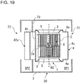
- Fig. 19 illustrates a configuration of the air-sending device 30 according to Embodiment 4 of the present disclosure. Parts having the same configurations as those of the centrifugal fan 1 and the other centrifugal fans in Figs. 1 to 10 are denoted by the same reference numerals, and a description thereof will be omitted.
- the air-sending device 30 according to Embodiment 4 is a ventilating fan or a desk fan, for example.
- the air-sending device 30 includes the centrifugal fan 1 according to Embodiment 1 or the centrifugal fan 1D according to Embodiment 2, and a case 7 accommodating the centrifugal fan 1 or 1D.
- the case 7 has two openings, namely, an air inlet 71 and an air outlet 72.
- the air-sending device 30 is configured such that the air inlet 71 and the air outlet 72 are formed in positions facing each other.
- the air inlet 71 and the air outlet 72 do not have to be formed in positions facing each other.
- either one of the air inlet 71 and the air outlet 72 may be formed on the top or the bottom of the centrifugal fan 1.
- a space SP1 including the portion where the air inlet 71 is formed and a space SP2 including the portion where the air outlet 72 is formed are separated by a partition plate 73.
- the centrifugal fan 1 is installed in a manner such that the air inlet 5 is located in the space SP1 where the air inlet 71 is formed and the air outlet 42a is located in the space SP2 where the air outlet 72 is formed.
- the air-sending device 30 when the fan 2 is driven and rotated by the motor 6, air is suctioned into the case 7 through the air inlet 71.
- the air suctioned into the case 7 is guided by the bell mouth 3 and suctioned into the fan 2.
- the air suctioned by the fan 2 is blown out to the radially outer side of the fan 2.
- the air blown out from the fan 2 passes through the inside of the scroll casing 4. Then, the air is blown out from the air outlet 42a of the scroll casing 4, and is blown out from the air outlet 72 of the case 7.
- the air-sending device 30 according to Embodiment 4 includes the centrifugal fan 1 according to Embodiment 1 or the centrifugal fan 1D according to Embodiment 2, it is possible to efficiently increase the pressure in the scroll portion 41. Further, the air-sending device 30 can achieve a reduction in noise level.
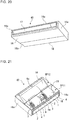
- Fig. 20 is a perspective view of the air-conditioning apparatus 40 according to Embodiment 5 of the present disclosure.
- Fig. 21 illustrates an inner configuration of the air-conditioning apparatus 40 according to Embodiment 5 of the present disclosure.
- Fig. 22 is a cross-sectional view of the air-conditioning apparatus 40 according to Embodiment 5 of the present disclosure.
- Fig. 23 is a cross-sectional view of a modified example of the air-conditioning apparatus 40 according to Embodiment 5 of the present disclosure. Note that parts having the same configurations as those of the centrifugal fan 1 and the other centrifugal fans in Figs. 1 to 10 are denoted by the same reference numerals, and a description thereof will be omitted. In Fig.
- the air-conditioning apparatus 40 according to Embodiment 5 includes at least one of the centrifugal fan 1 according to Embodiment 1 and the centrifugal fan 1D according to Embodiment 2, and a heat exchanger 10 disposed in a position facing the air outlet 42a of the at least one of the centrifugal fans 1 and 1D.
- the air-conditioning apparatus 40 according to Embodiment 5 includes a case 16 installed above a ceiling of an air-conditioned room.
- the centrifugal fan 1 is either one of the centrifugal fan 1 according to Embodiment 1 and the centrifugal fan 1D according to Embodiment 2.
- the case 16 is formed in the shape of a rectangular parallelepiped, including the upper surface portion 16a, a lower surface portion 16b, and side surface portions 16c.
- the shape of the case 16 is not limited to a rectangular parallelepiped, and may be another shape such as a cylindrical shape, the shape of a prism, a conical shape, a shape having a plurality of corners, or a shape having a plurality of curved surfaces.
- the case 16 includes, among the side surface portions 16c, the side surface portion 16c having a case air outlet 17.
- the case air outlet 17 is formed in a rectangular shape. Note that the shape of the case air outlet 17 is not limited to a rectangular shape.
- the shape of the case air outlet 17 may be a circular shape or an oval shape, or may be another shape.
- the case 16 includes, among the side surface portions 16c, the side surface portion 16c having a case air inlet 18 on the side opposite to the side with the case air outlet 17.
- the case air inlet 18 is formed in a rectangular shape.
- the shape of the case air inlet 18 is not limited to a rectangular shape.
- the shape of the case air inlet 18 may a circular shape or an oval shape, or may be another shape.
- a filter for removing dust in the air may be disposed at the case air inlet 18.
- the case 16 accommodates therein two centrifugal fans 1, a fan motor 9, and the heat exchanger 10.
- Each of the centrifugal fans 1 includes the fan 2, and the scroll casing 4 having the bell mouth 3.
- the fan motor 9 is supported by a motor support 9a fixed to the upper surface portion 16a of the case 16.
- the fan motor 9 includes an output shaft 6a.
- the output shaft 6a is disposed to extend in a direction parallel to the side surface portion 16c having the case air inlet 18 and the side surface portion 16c having the case air outlet 17.
- two fans 2 are attached to the output shaft 6a.
- the fans 2 generate the flow of air that is suctioned into the case 16 from the case air inlet 18 and blown out from the case air outlet 17 into the air-conditioned space.
- the number of centrifugal fans 1 disposed in the case 16 is not limited to two and may be one or three or more.
- each centrifugal fan 1 is mounted on a partition plate 19.
- the inner space of the case 16 is divided into a space SP11 on the inlet side of the scroll casing 4 and a space SP12 on the outlet side of the scroll casing 4 by the partition plate 19.
- the heat exchanger 10 is disposed in a position facing the air outlet 42a of each centrifugal fan 1, and is disposed on the flow passage of the air discharged from the centrifugal fan 1 in the case 16.
- the heat exchanger 10 adjusts the temperature of the air that is suctioned into the case 16 from the case air inlet 18 and blown out from the case air outlet 17 into the air-conditioned space.
- the heat exchanger 10 used herein may be one having a well-known structure.
- the case air inlet 18 only needs to be formed in a position perpendicular to the axial direction of the rotation shaft RS of the centrifugal fan 1.
- the case air inlet 18 may be formed in the lower surface portion 16b.
- Fig. 24 is a partially enlarged view of a part C of the modified example of the air-conditioning apparatus 40 of Fig. 23 .
- Fig. 25 is a partially enlarged view of a part C of another modified example of the air-conditioning apparatus 40 of Fig. 23 .
- the arrows illustrated in Figs. 24 and 25 indicate the flow of gas to be suctioned into the case 16.
- the centrifugal fan 1 is formed such that the closest portion 41c is disposed between a case wall portion 16S having a case air inlet 18a and a virtual plane portion VS passing through the rotation shaft RS of the fan 2 and parallel to the case wall portion 16S.
- the centrifugal fan 1 is configured such that the closest portion 41c is shifted from the third reference line BL3 toward the inner end 41a by an angle ⁇ '. That is, the closest portion 41c is disposed between the third reference line BL3 and the inner end 41a.
- the angle between the first reference line BL1 and the third reference line BL3 is about 90 degrees in the rotation direction R.
- the position of the third reference line BL3 is not limited to the position where the angle between the first reference line BL1 and the third reference line BL3 is about 90 degrees.
- the angle between the first reference line BL1 and the third reference line BL3 may be about 180 degrees in the rotation direction R.
- the centrifugal fan 1 is formed such that the closest portion 41c is disposed between the case wall portion 16S having a case air inlet 18 and a virtual plane portion VS passing through the rotation shaft RS of the fan 2 and parallel to the case wall portion 16S. That is, the third reference line BL3 only needs to be a line extending from the rotation shaft RS of the fan 2 and perpendicular to the case wall portion 16S having a case air inlet, in a cross-section perpendicular to the rotation shaft RS.
- the air-conditioning apparatus 40 according to Embodiment 5 includes the centrifugal fan 1 according to Embodiment 1 or the centrifugal fan 1D according to Embodiment 2, it is possible to efficiently increase the pressure in the scroll portion 41. Further, the air-sending device 30 can achieve a reduction in noise level.
- the centrifugal fan 1 housed in the air-conditioning apparatus 40 is configured such that the closest portion 41c is shifted from the third reference line BL3 toward the inner end 41a by the angle ⁇ '. Therefore, the centrifugal fan 1 housed in the air-conditioning apparatus 40 can increase the suction air volume and the distance for increasing the pressure in the scroll portion 41.
- Fig. 26 illustrates a configuration of the refrigeration cycle apparatus 50 according to Embodiment 6 of the present disclosure.
- the centrifugal fan 1 according to Embodiment 1 or the centrifugal fan 1D according to Embodiment 2 is used in an indoor unit 200 of the refrigeration cycle apparatus 50 according to Embodiment 6.
- the refrigeration cycle apparatus 50 is used for conditioning air.
- the refrigeration cycle apparatus 50 is not limited to those used for air-conditioning purposes.
- the refrigeration cycle apparatus 50 is used for refrigeration purposes or air-conditioning purposes, and applicable to apparatuses such as a refrigerator or a freezer, a vending machine, an air-conditioning apparatus, a refrigeration apparatus, and a water heater.
- the refrigeration cycle apparatus 50 according to Embodiment 6 performs air conditioning, by heating or cooling the room through transfer of heat between the outside air and the indoor air via refrigerant.
- the refrigeration cycle apparatus 50 according to Embodiment 6 includes an outdoor unit 100 and the indoor unit 200.
- the outdoor unit 100 and the indoor unit 200 are connected via refrigerant pipes 300 and 400 to form a refrigerant circuit in which refrigerant circulates.
- the refrigerant pipe 300 is a gas pipe through which refrigerant in a gas phase flows
- the refrigerant pipe 400 is a liquid pipe through which refrigerant in a liquid phase flows. Note that two-phase gas-liquid refrigerant may flow through the refrigerant pipe 400.
- a compressor 101, a flow switching device 102, an outdoor heat exchanger 103, an expansion valve 105, and an indoor heat exchanger 201 are sequentially connected via the refrigerant pipes.
- the outdoor unit 100 includes the compressor 101, the flow switching device 102, the outdoor heat exchanger 103, and the expansion valve 105.
- the compressor 101 compresses and discharges the suctioned refrigerant.
- the compressor 101 may include an inverter device, and may be configured such that the inverter device changes the operating frequency to change the capacity of the compressor 101. Note that the capacity of the compressor 101 is the amount of refrigerant discharged therefrom per unit time.
- the flow switching device 102 is, for example, a four-way valve, and is configured to switch the direction of the refrigerant flow passage.
- the refrigeration cycle apparatus 50 switches the flow of refrigerant with use of the flow switching device 102 based on an instruction from a controller 110, thereby performing a heating operation or a cooling operation.
- the outdoor heat exchanger 103 exchanges heat between the refrigerant and the outdoor air.
- the outdoor heat exchanger 103 serves as an evaporator to exchange heat between the low-pressure refrigerant having entered from the refrigerant pipe 400 and the outdoor air, and evaporate and gasify the refrigerant.
- the outdoor heat exchanger 103 serves as a condenser to exchange heat between the refrigerant compressed by the compressor 101 and having entered from the flow switching device 102 side and the outdoor air to condense and liquefy the refrigerant.
- the outdoor heat exchanger 103 is provided with an outdoor fan 104 to increase the heat exchange efficiency between the refrigerant and the outdoor air.
- An inverter device may be attached to the outdoor fan 104 to change the operating frequency of a fan motor and thereby change the rotation speed of the fan.
- the expansion valve 105 is an expansion device (flow rate control means) that serves as an expansion valve by adjusting the flow rate of the refrigerant flowing through the expansion valve 105.
- the expansion valve 105 adjusts the pressure of the refrigerant by changing the opening degree. For example, if the expansion valve 105 is an electronic expansion valve, the opening degree is adjusted based on an instruction from the controller 110 or other units.
- the indoor unit 200 includes the indoor heat exchanger 201 configured to exchange heat between the refrigerant and the indoor air, and an indoor fan 202 configured to adjust the flow of air with which the indoor heat exchanger 201 performs heat exchange.
- the indoor heat exchanger 201 serves as a condenser to exchange heat between the refrigerant having entered from the refrigerant pipe 300 and the indoor air, condense and liquefy the refrigerant, and discharge the refrigerant toward the refrigerant pipe 400.
- the indoor heat exchanger 201 serves as an evaporator to exchange heat between the refrigerant decompressed by the expansion valve 105 and the indoor air, evaporate and gasify the refrigerant through removal of heat from the air, and discharge the refrigerant toward the refrigerant pipe 300.
- the indoor fan 202 is disposed to face the indoor heat exchanger 201.
- the indoor fan 202 may be any one or more of the centrifugal fan 1 according to Embodiment 1 and the centrifugal fan 1D according to Embodiment 2.
- the operation speed of the indoor fan 202 is specified by the user's setting.
- An inverter device may be attached to the indoor fan 202 to change the operating frequency of a fan motor (not illustrated) and thereby change the rotation speed of the fan 2.
- the following describes a cooling operation as an example operation of the refrigeration cycle apparatus 50.
- High-temperature high-pressure gas refrigerant compressed and discharged by the compressor 101 flows into the outdoor heat exchanger 103 via the flow switching device 102.
- the gas refrigerant that has flowed into the outdoor heat exchanger 103 is condensed through heat exchange with the outside air sent by the outdoor fan 104 to become low-temperature refrigerant.
- the refrigerant is discharged from the outdoor heat exchanger 103.
- the refrigerant discharged from the outdoor heat exchanger 103 is expanded and decompressed by the expansion valve 105 to become low-temperature low-pressure two-phase gas-liquid refrigerant.
- the two-phase gas-liquid refrigerant flows into the indoor heat exchanger 201 of the indoor unit 200, and evaporates through heat exchange with the indoor air sent by the indoor fan 202 to become low-temperature low-pressure gas refrigerant. Then, the refrigerant is discharged from the indoor heat exchanger 201. The indoor air cooled through heat removal by the refrigerant is blown out as conditioned air from the air outlet of the indoor unit 200 into the air-conditioned space. The gas refrigerant discharged from the indoor heat exchanger 201 is suctioned into the compressor 101 via the flow switching device 102, and compressed again. The operation above is repeated.
- the following describes a heating operation as an example operation of the refrigeration cycle apparatus 50.
- High-temperature high-pressure gas refrigerant compressed and discharged by the compressor 101 flows into the indoor heat exchanger 201 of the indoor unit 200 via the flow switching device 102.
- the gas refrigerant that has flowed into the indoor heat exchanger 201 is condensed through heat exchange with the indoor air sent by the indoor fan 202 to become low-temperature refrigerant.
- the refrigerant is discharged from the indoor heat exchanger 201.
- the indoor air heated by receiving heat from the gas refrigerant is blown out as conditioned air from the air outlet of the indoor unit 200 into the air-conditioned space.
- the refrigerant discharged from the indoor heat exchanger 201 is expanded and decompressed by the expansion valve 105 to become low-temperature low-pressure two-phase gas-liquid refrigerant.
- the two-phase gas-liquid refrigerant flows into the outdoor heat exchanger 103 of the outdoor unit 100, and evaporates through heat exchange with the outside air sent by the outdoor fan 104 to become low-temperature low-pressure gas refrigerant. Then, the refrigerant is discharged from the outdoor heat exchanger 103.
- the gas refrigerant discharged from the outdoor heat exchanger 103 is suctioned into the compressor 101 via the flow switching device 102, and compressed again. The operation above is repeated.
- the refrigeration cycle apparatus 50 according to Embodiment 6 includes the centrifugal fan 1 according to Embodiment 1 or the centrifugal fan 1D according to Embodiment 2, it is possible to efficiently increase the pressure in the scroll portion 41. Further, the air-sending device 30 can achieve a reduction in noise level.
Landscapes
- Engineering & Computer Science (AREA)
- Mechanical Engineering (AREA)
- General Engineering & Computer Science (AREA)
- Chemical & Material Sciences (AREA)
- Combustion & Propulsion (AREA)
- Structures Of Non-Positive Displacement Pumps (AREA)
Abstract
Description
- The present disclosure relates to a centrifugal fan including a scroll casing; and an air-sending device, an air-conditioning apparatus, and a refrigeration cycle apparatus including the centrifugal fan.
- A conventional centrifugal fan includes a fan including a main plate on a disk and a plurality of blades in a scroll casing, and a tongue portion required for blowing out, in the centrifugal direction, the air that has entered from an air inlet formed at an end of the fan in the rotation axis direction, and increasing the pressure thereof. In the centrifugal fan, when the airflow in the scroll casing that has entered from the air inlet moves toward an air outlet, part of the airflow branches off at the tongue portion and enters the scroll again. Here, a gas passage formed between the tongue portion and the blades suddenly narrows, so that a large pressure difference is generated between the airflow moving toward the air outlet and the airflow entering the scroll again. This causes an increase in noise level. In view of the above, there has been proposed a centrifugal fan in which the position where the clearance between a scroll casing and an outer periphery of a fan is minimum is shifted from a tongue portion in the blade rotation direction (see Patent Literature 1). In a centrifugal fan of
Patent Literature 1, the position where the clearance between a scroll casing and an outer periphery of a fan is minimum is shifted from a tongue portion in the blade rotation direction, thereby reducing a sudden pressure difference in the tongue portion, and reducing the noise level. - Patent Literature 1:
Japanese Unexamined Patent Application Publication No.09 - 242697 - However, in the centrifugal fan of
Patent Literature 1, since the position where the clearance between the scroll casing and the outer periphery of the fan is minimum is shifted from the tongue portion in the blade rotation direction, the volume of gas flowing through a flow passage from the tongue portion to this position is reduced. Therefore, the centrifugal fan ofPatent Literature 1 may not be able to efficiently increase the pressure in a scroll portion formed in a volute shape. - The present disclosure has been made to solve the above problem, and an object thereof is to provide a centrifugal fan, an air-sending device, an air-conditioning apparatus, and a refrigeration cycle apparatus that are capable of efficiently increasing the pressure in a scroll portion even in the case where the position where the clearance between a scroll casing and an outer periphery of a fan is minimum is shifted from a tongue portion in the blade rotation direction.
- A centrifugal fan according to an embodiment of the present disclosure includes a fan configured to be driven to rotate; and a scroll casing housing the fan; the scroll casing including a peripheral wall having a volute shape having an inner end of a spiral thereof at a boundary with a tongue portion of the scroll casing, the tongue portion being configured to guide airflow generated by the fan, the peripheral wall including, when a portion at the peripheral wall at which a distance between the peripheral wall and a rotation shaft of the fan is minimum is defined as a closest portion, a narrowed portion at which the distance between the peripheral wall and the rotation shaft is reduced from the inner end toward the closest portion in a rotation direction of the fan, and an expanded portion that is formed between the narrowed portion and the closest portion and at which the distance between the peripheral wall and the rotation shaft is increased.
- The centrifugal fan according to the above embodiment of the present disclosure includes the narrowed portion at which the distance between the peripheral wall and the rotation shaft is reduced from the inner end toward the closest portion in the rotation direction of the fan, and the expanded portion that is formed between the narrowed portion and the closest portion and at which the distance between the peripheral wall and the rotation shaft is increased. Therefore, in the centrifugal fan, the distance between the peripheral wall and the outer peripheral portion of the fan is gradually reduced from the tongue portion toward the closest portion, and then the distance between the peripheral wall and the outer peripheral portion of the fan is increased in front of the closest portion. In the centrifugal fan, since the distance between the peripheral wall and the outer peripheral portion of the fan is increased in front of the closest portion, the air volume is secured. Further, as the gas of the secured volume passes through the closest portion, the velocity of the gas is increased. Accordingly, the centrifugal fan can effectively increase the pressure in the scroll portion.
-
- [
Fig. 1] Fig. 1 is a perspective view of a centrifugal fan according toEmbodiment 1 of the present disclosure. - [
Fig. 2] Fig. 2 is a schematic diagram of the centrifugal fan according toEmbodiment 1 of the present disclosure as viewed from an air inlet side thereof. - [
Fig. 3] Fig. 3 is an enlarged view of a part B of the centrifugal fan ofFig. 2 . - [
Fig. 4] Fig. 4 is a graph illustrating a relationship between an angle θ and a distance L in each of the centrifugal fan ofFig. 3 and a centrifugal fan of a comparative example. - [
Fig. 5] Fig. 5 is an enlarged view of modified examples of the centrifugal fan according toEmbodiment 1 of the present disclosure. - [
Fig. 6] Fig. 6 is a graph illustrating a relationship between an angle θ and a distance L in each of the modified examples of the centrifugal fan according toEmbodiment 1 of the present disclosure and the centrifugal fan of the comparative example. - [
Fig. 7] Fig. 7 is a partially enlarged view of a centrifugal fan according toEmbodiment 2 of the present disclosure. - [
Fig. 8] Fig. 8 is a graph illustrating a relationship between an angle θ and a distance L in each of the centrifugal fan ofFig. 7 and the centrifugal fan of the comparative example. - [
Fig. 9] Fig. 9 is an enlarged view of modified examples of the centrifugal fan according toEmbodiment 2 of the present disclosure. - [
Fig. 10] Fig. 10 is a graph illustrating a relationship between an angle θ and a distance L in each of the modified examples of the centrifugal fan according toEmbodiment 2 of the present disclosure and the centrifugal fan of the comparative example. - [
Fig. 11] Fig. 11 is a schematic diagram of a centrifugal fan according toEmbodiment 3 of the present disclosure as viewed from an air inlet side thereof. - [
Fig. 12] Fig. 12 is an enlarged view of a part B2 of the centrifugal fan ofFig. 11 . - [
Fig. 13] Fig. 13 is a cross-sectional view taken along line B-B ofFig. 12 . - [
Fig. 14] Fig. 14 is a cross-sectional view of a modified example 1 of the centrifugal fan according toEmbodiment 3 of the present disclosure. - [
Fig. 15] Fig. 15 is a cross-sectional view of a modified example 2 of the centrifugal fan according toEmbodiment 3 of the present disclosure. - [
Fig. 16] Fig. 16 is a cross-sectional view of a modified example 3 of the centrifugal fan according toEmbodiment 3 of the present disclosure. - [
Fig. 17] Fig. 17 is a cross-sectional view of a modified example 4 of the centrifugal fan according toEmbodiment 3 of the present disclosure. - [
Fig. 18] Fig. 18 is a cross-sectional view of a modified example 5 of the centrifugal fan according toEmbodiment 3 of the present disclosure. - [
Fig. 19] Fig. 19 illustrates a configuration of an air-sending device according toEmbodiment 4 of the present disclosure. - [
Fig. 20] Fig. 20 is a perspective view of an air-conditioning apparatus according toEmbodiment 5 of the present disclosure. - [
Fig. 21] Fig. 21 illustrates an inner configuration of the air-conditioning apparatus according toEmbodiment 5 of the present disclosure. - [
Fig. 22] Fig. 22 is a cross-sectional view of the air-conditioning apparatus according toEmbodiment 5 of the present disclosure. - [
Fig. 23] Fig. 23 is a cross-sectional view of a modified example of the air-conditioning apparatus according toEmbodiment 5 of the present disclosure. - [
Fig. 24] Fig. 24 is a partially enlarged view of a part C of the modified example of the air-conditioning apparatus ofFig. 23 . - [
Fig. 25] Fig. 25 is a partially enlarged view of a part C of another modified example of the air-conditioning apparatus ofFig. 23 . - [
Fig. 26] Fig. 26 illustrates a configuration of a refrigeration cycle apparatus according toEmbodiment 6 of the present disclosure. - Hereinafter,
centrifugal fans sending device 30, an air-conditioning apparatus 40, and arefrigeration cycle apparatus 50 according to Embodiments of the present disclosure will also be described with reference to the drawings. Note that in the drawings includingFig. 1 to be referred to below, the relative dimensional relationship between the components, the shape, and other features thereof may differ from the actual ones. Further, in the drawings to be referred to below, identical reference numerals designate identical or equivalent components, and this applies throughout the description. Terms indicating directions (such as "up", "down", "right", "left", "front", and "rear") are used as appropriate, for facilitating understanding. However, these expressions are described as such for purposes of explanation, and the arrangement and the orientations of the devices or the parts are not limited thereby. -
Fig. 1 is a perspective view of thecentrifugal fan 1 according toEmbodiment 1 of the present disclosure.Fig. 2 is a schematic diagram of thecentrifugal fan 1 according toEmbodiment 1 of the present disclosure as viewed from anair inlet 5 side thereof. Note thatFig. 2 is a schematic diagram illustrating a cross-section of the center portion of ascroll casing 4 in the axial direction of a below-described rotation shaft RS. In the following, a description will be given with reference to the cross-section of the center portion of thescroll casing 4 in the axial direction of the rotation shaft RS. However, a cross-section of another portion of thescroll casing 4 may be referred to. The configuration of thecentrifugal fan 1 described below only needs to be present at least a part thereof in the axial direction of the rotation shaft RS, and may be present in the entire region thereof in the axial direction of the rotation shaft RS. A basic structure of thecentrifugal fan 1 will be described with reference toFigs. 1 and 2 . Thecentrifugal fan 1 is a multi-blade centrifugal-typecentrifugal fan 1 such as a sirocco fan or a turbofan, and includes afan 2 configured to generate airflow, and thescroll casing 4 housing thefan 2. - The
fan 2 is configured to be driven by a motor or other devices (not illustrated) to rotate, and forcibly send air radially outward by a centrifugal force generated by the rotation. As illustrated inFig. 1 , thefan 2 includes a disk-shapedmain plate 2a and a plurality ofblades 2d disposed at a peripheral edge portion 2a1 of themain plate 2a. Themain plate 2a only needs to have a plate shape, and may have a shape (such as a polygonal shape) other than a disk shape. Ashaft portion 2b to which the motor (not illustrated) is connected is disposed at the center of themain plate 2a. Thefan 2 is formed in a cylindrical shape by themain plate 2a and the plurality ofblades 2d, and hasair inlets 2e, one at each end opposite to themain plate 2a in the axial direction of the rotation shaft RS of thefan 2. Theair inlets 2e allow gas to enter the space surrounded by themain plate 2a and the plurality ofblades 2d. - The plurality of
blades 2d are arranged circumferentially about theshaft portion 2b, and proximal ends thereof are fixed to themain plate 2a. The plurality ofblades 2d are disposed on both sides of themain plate 2a in the axial direction of the rotation shaft RS of theshaft portion 2b. Note that in the case of a single-inletcentrifugal fan 1 having only oneair inlet 5, the plurality ofblades 2d may be disposed on only one side of themain plate 2a in the axial direction of the rotation shaft RS of theshaft portion 2b. Theblades 2d are spaced at regular intervals from each other at the peripheral edge portion 2a1 of themain plate 2a. Eachblade 2d is formed in, for example, a curved rectangular plate shape, and is disposed in parallel to the radial direction or inclined at a predetermined angle with respect to the radial direction. - The
fan 2 is driven to rotate about the rotation shaft RS when the motor (not illustrated) is driven. As thefan 2 rotates, gas outside thecentrifugal fan 1 passes through theair inlets 5 formed in thescroll casing 4 and theair inlets 2e of thefan 2, and is suctioned into the space surrounded by themain plate 2a and the plurality ofblades 2d. Then, as thefan 2 rotates, the air suctioned into the space surrounded by themain plate 2a and the plurality ofblades 2d passes between theadjacent blades 2d, and is sent radially outward. Note that inEmbodiment 1, eachblade 2d is disposed upright to be substantially perpendicular to themain plate 2a. However, the configuration is not limited thereto. Eachblade 2d may be inclined to the perpendicular direction of themain plate 2a. - The
scroll casing 4 houses thefan 2, and straightens the air blown out from thefan 2. Thescroll casing 4 includes ascroll portion 41 and anoutlet portion 42. - The
scroll portion 41 forms an air flow passage configured to convert a dynamic pressure of the airflow generated by thefan 2 to a static pressure. Thescroll portion 41 includesside walls 4a each covering thefan 2 in the axial direction of the rotation shaft RS of theshaft portion 2b of thefan 2 and having theair inlet 5 configured to suction air, and aperipheral wall 4c surrounding thefan 2 in the radial direction of the rotation shaft RS of theshaft portion 2b of thefan 2. Thescroll portion 41 further includes atongue portion 43 disposed between theoutlet portion 42 and aninner end 41a of theperipheral wall 4c to define a curved surface, and configured to guide the airflow generated by thefan 2 to anair outlet 42a via thescroll portion 41. Note that the radial direction of the rotation shaft RS is a direction perpendicular to the rotation shaft RS. An inner space in thescroll portion 41 defined by theperipheral wall 4c and theside walls 4a is a space in which the air blown out from thefan 2 flows along theperipheral wall 4c. - Each
side wall 4a is disposed substantially perpendicular to the axial direction of the rotation shaft RS of thefan 2 to cover thefan 2. Theair inlet 5 is formed in theside wall 4a of thescroll casing 4 to allow air to flow between thefan 2 and the outside of thescroll casing 4. Theair inlet 5 is formed in a circular shape, and is disposed such that the center of theair inlet 5 substantially coincides with the center of theshaft portion 2b of thefan 2. With this configuration of theside wall 4a, the air in the vicinity of theair inlet 5 smoothly flows, and efficiently enters thefan 2 from theair inlet 5. Thecentrifugal fan 1 includes thescroll casing 4 of a double-inlet type that has theside walls 4a each having theair inlet 5, one on each side of themain plate 2a in the axial direction of the rotation shaft RS of theshaft portion 2b. That is, thecentrifugal fan 1 includes thescroll casing 4 having twoside walls 4a, and theside walls 4a are disposed to face each other. Note that thecentrifugal fan 1 may include ascroll casing 4 of a single-inlet type that has theside wall 4a having theair inlet 5, only on one side of themain plate 2a in the axial direction of the rotation shaft RS of theshaft portion 2b. In this case, thescroll casing 4 of thecentrifugal fan 1 has theside wall 4a having theair inlet 5, and a side wall (not illustrated) having noair inlet 5 and disposed to face theside wall 4a. - The
air inlet 5 formed in theside wall 4a is defined by abell mouth 3. Thebell mouth 3 straightens the flow of gas to be suctioned into thefan 2 to guide the gas into theair inlet 2e of thefan 2. Thebell mouth 3 is formed such that its opening diameter gradually decreases from the outer side toward the inner side of thescroll casing 4. - The
peripheral wall 4c surrounds thefan 2 in the radial direction of theshaft portion 2b to define an inner peripheral surface facing the plurality ofblades 2d. Theperipheral wall 4c faces the air outlet side of theblades 2d of thefan 2. Theperipheral wall 4c is disposed substantially parallel to the axial direction of the rotation shaft RS of thefan 2 to cover thefan 2. As illustrated inFig. 2 , theperipheral wall 4c extends from theinner end 41a located at the boundary with thetongue portion 43 to anouter end 41b located at the boundary between theoutlet portion 42 and thescroll portion 41 on the side far from thetongue portion 43 in a rotation direction R of thefan 2. Theinner end 41a corresponds to an end on the upstream side of the airflow generated by the rotation of thefan 2, and theouter end 41b corresponds to an end on the downstream side of the airflow generated by the rotation of thefan 2, at theperipheral wall 4c forming a curved surface. - The
peripheral wall 4c has a width in the axial direction of the rotation shaft RS of thefan 2. Theperipheral wall 4c is formed in a volute shape. The volute shape may be, for example, a volute shape based on a logarithm spiral, an Archimedean spiral, or an involute curve. The inner peripheral surface of theperipheral wall 4c forms a curved surface that is smoothly curved from theinner end 41a as a scroll start end of the volute shape to theouter end 41b as a scroll terminal end of the volute shape in the circumferential direction of thefan 2. With this configuration, the air sent from thefan 2 smoothly flows through the clearance between thefan 2 and theperipheral wall 4c toward theoutlet portion 42. Therefore, in thescroll casing 4, the static pressure of air is effectively increased from thetongue portion 43 toward theoutlet portion 42. The configuration of theperipheral wall 4c will be described below in detail. - The
outlet portion 42 defines theair outlet 42a through which the airflow generated by thefan 2 and having passed through thescroll portion 41 is discharged. Theoutlet portion 42 is formed of a hollow pipe having a rectangular shape in a cross-section orthogonal to the direction of the airflow flowing along theperipheral wall 4c. As illustrated inFigs. 1 and 2 , theoutlet portion 42 defines a flow passage that guides the air sent from thefan 2 and flowing though the clearance between theperipheral wall 4c and thefan 2 to discharge the air to the outside of thescroll casing 4. - As illustrated in
Fig. 1 , theoutlet portion 42 includes anextension plate 42b, adiffuser plate 42c, afirst side plate 42d, and asecond side plate 42e. Theextension plate 42b smoothly continues to theouter end 41b on the downstream side of theperipheral wall 4c, and is formed integrally with theperipheral wall 4c. Thediffuser plate 42c is formed integrally with thetongue portion 43 of thescroll casing 4, and faces theextension plate 42b. Thediffuser plate 42c is formed at a predetermined angle with respect to theextension plate 42b such that the cross-sectional area of the flow passage gradually increases in the direction of the airflow in theoutlet portion 42. Thefirst side plate 42d is formed integrally with theside wall 4a of thescroll casing 4, and thesecond side plate 42e is formed integrally with theside wall 4a on the opposite side of thescroll casing 4. Thefirst side plate 42d and thesecond side plate 42e are formed between theextension plate 42b and thediffuser plate 42c. In this manner, theoutlet portion 42 has a flow passage with a rectangular cross-sectional shape defined by theextension plate 42b, thediffuser plate 42c, thefirst side plate 42d, and thesecond side plate 42e. - The
tongue portion 43 is formed between thediffuser plate 42c of theoutlet portion 42 and theinner end 41a of theperipheral wall 4c in thescroll casing 4. Thetongue portion 43 minimizes the air flowing from the scroll terminal end to the scroll start end of the volute-shaped flow passage. Thetongue portion 43 is disposed on the upstream side of the air flow passage, and serves to separate between an airflow flowing in the rotation direction R of thefan 2 and an airflow flowing from the downstream of the air flow passage to theair outlet 42a. Thetongue portion 43 is disposed at the boundary portion between thescroll portion 41 and theoutlet portion 42, and is a protrusion expanding toward the inner side of thescroll casing 4. Thetongue portion 43 extends in a direction parallel to the axial direction of the rotation shaft RS of theshaft portion 2b in thescroll casing 4. Thetongue portion 43 is disposed between the end of theoutlet portion 42 and theinner end 41a of theperipheral wall 4c to define a curved surface, and configured to guide the airflow generated by thefan 2 to theair outlet 42a via thescroll portion 41. - The
tongue portion 43 is formed to have a predetermined curvature radius, and theperipheral wall 4c is smoothly connected to thediffuser plate 42c via thetongue portion 43. When the air having passed through thefan 2 from theair inlet 5 and sent out therefrom is collected by thescroll casing 4 and enters theoutlet portion 42, thetongue portion 43 serves as a branching point of the flow passage of the air. That is, at the inlet port of theoutlet portion 42, an airflow moving toward theair outlet 42a and an airflow flowing again to the upstream side from thetongue portion 43. Further, when the airflow passes through thescroll casing 4, its static pressure increases. Therefore, the airflow entering theoutlet portion 42 has a pressure higher than the pressure in thescroll casing 4. Accordingly, thetongue portion 43 has a function for separating such different pressures, and guiding the air that is to enter theoutlet portion 42 to each flow passage. -
Fig. 3 is an enlarged view of a part B of thecentrifugal fan 1 ofFig. 2 . Note that inFig. 3 , theperipheral wall 4c of thecentrifugal fan 1 ofEmbodiment 1 is indicated by the long-dashed line for comparison with a below-described reference peripheral wall CL. The structure of thecentrifugal fan 1 ofEmbodiment 1 will be described with reference toFigs. 2 and3 . - An outer peripheral portion FL illustrated in
Figs. 2 and3 is an outer peripheral portion of thefan 2. The outer peripheral portion FL is in the position of the edges of theblades 2d located at the outermost periphery of thefan 2 in plan view as viewed in the axial direction of the rotation shaft RS of thecentrifugal fan 1. The distance between the outer peripheral portion FL and the rotation shaft RS is constant throughout. Note that the edges of theblades 2d refer to the radially outer edge of thefan 2. - The reference peripheral wall CL illustrated in
Fig. 3 represents a peripheral wall of a centrifugal fan of a comparative example. The reference peripheral wall CL is a virtual peripheral wall configured such that theperipheral wall 4c approaches the rotation shaft RS at a constant rate from theinner end 41a toward a below-describedclosest portion 41c. - The
closest portion 41c is a portion that is located between theinner end 41a and theouter end 41b of the reference peripheral wall CL and at which the distance between the reference peripheral wall CL and the rotation shaft RS is minimum. In other words, theclosest portion 41c is a portion that is located between theinner end 41a and theouter end 41b of the reference peripheral wall CL and at which the distance between the reference peripheral wall CL and the outer peripheral portion FL of thefan 2 is minimum. A portion that is located between theinner end 41a and theouter end 41b of theperipheral wall 4c and at which the distance between theperipheral wall 4c of thescroll casing 4 and the rotation shaft RS is minimum is also defined as theclosest portion 41c. In other words, theclosest portion 41c is a portion that is located between theinner end 41a and theouter end 41b of theperipheral wall 4c and at which the distance between theperipheral wall 4c of thescroll casing 4 and the outer peripheral portion FL of thefan 2 is minimum. - The centrifugal fan of the comparative example has a structure in which the
closest portion 41c is shifted from thetongue portion 43 in the rotation direction R of thefan 2. Thecentrifugal fan 1 according toEmbodiment 1 also has a structure in which theclosest portion 41c is shifted from thetongue portion 43 in the rotation direction R of thefan 2. Note that although theclosest portion 41c is formed in the position rotated by about 90 degrees from theinner end 41a in the circumferential direction of the rotation shaft RS inFigs. 2 and3 , the position where theclosest portion 41c is formed is not limited to the position rotated by about 90 degrees from theinner end 41a. Theclosest portion 41c only needs to be formed in a position between theinner end 41a and theouter end 41b. For example, theclosest portion 41c may be formed in the position rotated by about 180 degrees from theinner end 41a. It is particularly preferable that theclosest portion 41c is formed near an air inlet of, for example, an indoor unit in which thecentrifugal fan 1 is disposed. Note that the relationship between theclosest portion 41c and an air inlet of an air-conditioning apparatus will be described below. - A first reference line BL1 is a virtual line connecting the rotation shaft RS to the
inner end 41a in a cross-section perpendicular to the rotation shaft RS. A second reference line BL2 is a virtual line connecting the rotation shaft RS to theclosest portion 41c in the cross-section perpendicular to the rotation shaft RS. - A distance L illustrated in
Fig. 2 represents the distance between the rotation shaft RS and theperipheral wall 4c or the reference peripheral wall CL. A distance LP illustrated inFig. 3 represents the distance between the rotation shaft RS and theperipheral wall 4c in the direction perpendicular to the rotation shaft RS. A distance LS represents the distance between the rotation shaft RS and the reference peripheral wall - A distance L1 represents the distance between the rotation shaft RS and the
inner end 41a of the peripheral wall of the centrifugal fan of the comparative example in the direction perpendicular to the rotation shaft RS. In other words, the distance L1 represents the length of the first reference line BL1. The distance L1 also represents the distance between the rotation shaft RS and theinner end 41a of theperipheral wall 4c in the direction perpendicular to the rotation shaft RS. That is, the inner ends 41a of the centrifugal fan of the comparative example and thecentrifugal fan 1 according toEmbodiment 1 are located in the same position in the circumferential direction and the radial direction of thefan 2. - A distance L2 represents the distance between the rotation shaft RS and the
closest portion 41c of the peripheral wall of the centrifugal fan of the comparative example in the direction perpendicular to the rotation shaft RS. In other words, the distance L2 represents the length of the second reference line BL2. The distance L2 also represents the distance between the rotation shaft RS and theclosest portion 41c of theperipheral wall 4c in the direction perpendicular to the rotation shaft RS. That is, theclosest portions 41c of the centrifugal fan of the comparative example and thecentrifugal fan 1 according toEmbodiment 1 are located in the same position in the circumferential direction and the radial direction of thefan 2. - An angle θ illustrated in
Fig. 2 is an angle rotated from the first reference line BL1 in the rotation direction R of thefan 2, in a region between the first reference line BL1 connecting the rotation shaft RS to theinner end 41a and the second reference line BL2 connecting the rotation shaft RS to theclosest portion 41c, in a cross-section perpendicular to the rotation shaft RS. An angle θP illustrated inFig. 3 is an angle in the circumferential direction rotated from theinner end 41a to a measurement position of the distance LP about the rotation shaft RS, in plan view as viewed in the axial direction of the rotation shaft RS of thecentrifugal fan 1. An angle θS is an angle in the circumferential direction rotated from theinner end 41a to a measurement position of the distance LS about the rotation shaft RS, in plan view as viewed in the axial direction of the rotation shaft RS of the centrifugal fan of the comparative example. - An angle θL is an angle in the circumferential direction rotated from the
inner end 41a to the position of theclosest portion 41c about the rotation shaft RS, in plan view as viewed in the axial direction of the rotation shaft RS of thecentrifugal fan 1. Note that although the angle θL is set to about 90 degrees inFigs. 2 and3 , the angle θL is not limited to about 90 degrees. The angle θL may be any angle between theinner end 41a to theouter end 41b. For example, the angle θL may be about 180 degrees. -
Fig. 4 is a graph illustrating a relationship between the angle θ and the distance L in each of thecentrifugal fan 1 ofFig. 3 and the centrifugal fan of the comparative example. The structure of thecentrifugal fan 1 will be described in greater detail with reference toFigs. 3 and 4 . - A reference line A-A' illustrated in
Fig. 4 represents a relationship between the angle θ of the reference peripheral wall CL and the distance LS in the region from theinner end 41a to theclosest portion 41c. As illustrated inFig. 4 , the reference peripheral wall CL is formed such that the distance LS decreases at a constant rate as the angle θ increases from theinner end 41a toward theclosest portion 41c. Accordingly, the centrifugal fan of the comparative example is formed such that the reference peripheral wall CL approaches the rotation shaft RS at a predetermined rate from theinner end 41a toward theclosest portion 41c. That is, the centrifugal fan of the comparative example is formed such that a gas flow passage narrows at a constant rate from theinner end 41a toward theclosest portion 41c. - A curved line PL indicated by the long-dashed line in
Fig. 4 represents a relationship between the angle θP of theperipheral wall 4c and the distance LP in the region from theinner end 41a to theclosest portion 41c. As illustrated inFigs. 3 and 4 , theperipheral wall 4c includes an expanded portion 4c1 between theinner end 41a and theclosest portion 41c. As illustrated inFigs. 3 and 4 , the expanded portion 4c1 is a portion of theperipheral wall 4c at which the distance LP between the rotation shaft RS and theperipheral wall 4c is greater than or equal to the distance LS between the rotation shaft RS and the reference peripheral wall CL. Compared to the virtual reference peripheral wall CL configured such that theperipheral wall 4c approaches the rotation shaft RS at a constant rate from theinner end 41a toward theclosest portion 41c, the expanded portion 4c1 is formed such that a part of theperipheral wall 4c expands in the radial direction of thefan 2. The expanded portion 4c1 is a portion that is located on theinner end 41a side of theclosest portion 41c and at which the distance between theperipheral wall 4c and the rotation shaft RS is increased. In other words, the expanded portion 4c1 is a portion that is located on theinner end 41a side of theclosest portion 41c and at which the distance between theperipheral wall 4c and the outer peripheral portion FL of thefan 2 is increased. Note that as illustrated inFig. 4 , the distance between theperipheral wall 4c and the rotation shaft RS at the expanded portion 4c1 is less than the distance between theperipheral wall 4c and the rotation shaft RS at theinner end 41a. - Note that as illustrated in
Fig. 4 , theperipheral wall 4c includes a narrowedportion 4d at which the distance between theperipheral wall 4c and the rotation shaft RS decreases from theinner end 41a toward theclosest portion 41c in the rotation direction R of thefan 2. The narrowedportion 4d is a portion of theperipheral wall 4c at which the distance between theperipheral wall 4c and the outer peripheral portion FL of thefan 2 decreases from theinner end 41a toward theclosest portion 41c in the rotation direction R of thefan 2. The narrowedportion 4d is formed to extend from theinner end 41a to the expanded portion 4c1 in the rotation direction R of thefan 2 such that the distance LP decreases at a constant rate as the angle θ increases from theinner end 41a toward theclosest portion 41c. Note that the rate at which the distance LP decreases as the angle θ increases is equal to the rate at which the distance LS decreases as the angle θ increases. That is, theperipheral wall 4c from theinner end 41a to the expanded portion 4c1 is formed such that the curved line PL has the same inclination as the reference line A-A'. - As illustrated in
Figs. 3 and 4 , theperipheral wall 4c includes a first inflection portion U1 and a second inflection portion M1 at the expanded portion 4c1. As illustrated inFig. 4 , the first inflection portion U1 is a minimum point of the curved line PL at the expanded portion 4c1, and the second inflection portion M1 is a maximum point of the curved line PL at the expanded portion 4c1. The first inflection portion U1 is a boundary portion between a part where theperipheral wall 4c approaches the rotation shaft RS and a part where theperipheral wall 4c separates from the rotation shaft RS, from theinner end 41a toward theclosest portion 41c. In other words, the first inflection portion U1 is a boundary portion between a part where theperipheral wall 4c approaches the outer peripheral portion FL of thefan 2 and a part where theperipheral wall 4c separates from the outer peripheral portion FL of thefan 2, from theinner end 41a toward theclosest portion 41c. The second inflection portion M1 is a boundary portion between the part where theperipheral wall 4c separates from the rotation shaft RS and a part where theperipheral wall 4c approaches the rotation shaft RS, from theinner end 41a toward theclosest portion 41c. In other words, the second inflection portion M1 is a boundary portion of the part where theperipheral wall 4c separates from the outer peripheral portion FL of thefan 2 and a part where theperipheral wall 4c approaches the outer peripheral portion FL of thefan 2, from theinner end 41a toward theclosest portion 41c. That is, as illustrated inFig. 4 , in terms of the relationship between the angle θP and the distance LP, the expanded portion 4c1 of theperipheral wall 4c is formed to have a downwardly protruding curved line and an upwardly protruding curved line in the direction from theinner end 41a toward theclosest portion 41c. Further, theperipheral wall 4c is configured to gradually separate from the rotation shaft RS, from the first inflection portion U1 to the second inflection portion M1 in the rotation direction R. That is, theperipheral wall 4c is configured to gradually separate from the outer peripheral portion FL of thefan 2, from the first inflection portion U1 to the second inflection portion M1 in the rotation direction R. Accordingly, in thecentrifugal fan 1, the gas flow passage between the first inflection portion U1 and the second inflection portion M1 widens in the rotation direction R. - As described above, the distance between the outer peripheral portion FL of the
fan 2 and the rotation shaft RS is constant throughout. Further, theperipheral wall 4c from theinner end 41a to the expanded portion 4c1 in the rotation direction R of thefan 2 is formed such that the distance LP decreases at a constant rate as the angle θ increases from theinner end 41a toward theclosest portion 41c. Therefore, in thecentrifugal fan 1, the distance between theperipheral wall 4c and theblades 2d gradually decreases from theinner end 41a toward the expanded portion 4c1. Further, thecentrifugal fan 1 includes the expanded portion 4c1. The distance between theperipheral wall 4c and theblades 2d at the expanded portion 4c1 is increased, compared to the distance between theperipheral wall 4c and theblades 2d in the region from theinner end 41a to the expanded portion 4c1. Note that thetongue portion 43 is formed on the upstream side of the airflow with respect to theinner end 41a, and theinner end 41a is formed at the downstream end of thetongue portion 43. With the configuration described above, in thecentrifugal fan 1, the distance between theperipheral wall 4c and the outer peripheral portion FL of thefan 2 is gradually reduced from thetongue portion 43 toward theclosest portion 41c, and then the distance between theperipheral wall 4c and the outer peripheral portion FL of thefan 2 is increased in front of theclosest portion 41c. That is, in thescroll casing 4, the gas flow passage formed between theperipheral wall 4c and the outer peripheral portion FL of thefan 2 is gradually narrowed at the narrowedportion 4d from theinner end 41a toward theclosest portion 41c, and then the gas flow passage is widened at the expanded portion 4c1. - When the
fan 2 rotates, the air outside thescroll casing 4 is suctioned into thescroll casing 4 through theair inlet 5. The air suctioned into thescroll casing 4 is guided by thebell mouth 3 and suctioned into thefan 2. In the course of passing between the plurality ofblades 2d, the air suctioned into thefan 2 is turned into an airflow with a dynamic pressure and a static pressure applied thereto, and is blown out to the radially outer side of thefan 2. In the airflow blown out from thefan 2, the dynamic pressure is converted into static pressure while the airflow is guided between the inner side of theperipheral wall 4c and theblades 2d in thescroll portion 41. The airflow passes through thescroll portion 41, and then is blown out to the outside of thescroll casing 4 from theair outlet 42a formed in theoutlet portion 42. - The
centrifugal fan 1 includes the narrowedportion 4d at which the distance between theperipheral wall 4c and the rotation shaft RS decreases from theinner end 41a toward theclosest portion 41c in the rotation direction R of thefan 2. The centrifugal fan further includes the expanded portion 4c1 that is formed between the narrowedportion 4d and theclosest portion 41c and at which the distance between theperipheral wall 4c and the rotation shaft RS is increased. Therefore, in thecentrifugal fan 1, the distance between theperipheral wall 4c and the outer peripheral portion FL of thefan 2 is gradually reduced from thetongue portion 43 toward theclosest portion 41c, and then the distance between theperipheral wall 4c and the outer peripheral portion FL of thefan 2 is increased in front of theclosest portion 41c. In thecentrifugal fan 1, since the distance between theperipheral wall 4c and the outer peripheral portion FL of thefan 2 is increased in front of theclosest portion 41c, the air volume is secured. Further, as the gas of the secured volume passes through theclosest portion 41c, the velocity of the gas is increased. Accordingly, thecentrifugal fan 1 can effectively increase the pressure in thescroll portion 41. - Further, in the
scroll casing 4, the gas flow passage formed between theperipheral wall 4c and the outer peripheral portion FL of thefan 2 is gradually narrowed at the narrowedportion 4d from theinner end 41a toward theclosest portion 41c, and then the flow passage is widened at the expanded portion 4c1. In thecentrifugal fan 1, since the distance between theperipheral wall 4c and the outer peripheral portion FL of thefan 2 is increased in front of theclosest portion 41c, the air volume is secured. Further, as the gas of the secured volume passes through theclosest portion 41c, the velocity of the gas is increased. Accordingly, thecentrifugal fan 1 can effectively increase the pressure in thescroll portion 41. - Compared to a virtual reference wall configured such that the
peripheral wall 4c approaches the rotation shaft RS at a constant rate from theinner end 41a toward theclosest portion 41c, the expanded portion 4c1 expands in the radial direction of thefan 2. Since the distance between theperipheral wall 4c and the outer peripheral portion FL of thefan 2 is increased in front of theclosest portion 41c, thecentrifugal fan 1 can secure the air volume. Further, as the gas of the secured volume passes through theclosest portion 41c, the velocity of the gas is increased. Accordingly, thecentrifugal fan 1 can effectively increase the pressure in thescroll portion 41. - The
peripheral wall 4c includes the first inflection portion U1 defining a boundary portion between a part where theperipheral wall 4c approaches the rotation shaft RS and a part where theperipheral wall 4c separates from the rotation shaft RS, and the second inflection portion M1 defining a boundary portion between the part where theperipheral wall 4c separates from the rotation shaft RS and a part where theperipheral wall 4c approaches the rotation shaft RS. In thecentrifugal fan 1, since the distance between theperipheral wall 4c and the outer peripheral portion FL of thefan 2 is increased in front of theclosest portion 41c, the air volume is secured. Further, as the gas of the secured volume passes through theclosest portion 41c, the velocity of the gas is increased. Accordingly, thecentrifugal fan 1 can effectively increase the pressure in thescroll portion 41. - Further, the
peripheral wall 4c is configured to gradually separate from the rotation shaft RS, from the first inflection portion U1 to the second inflection portion M1. Since the distance between theperipheral wall 4c and the outer peripheral portion FL of thefan 2 is increased in front of theclosest portion 41c, thecentrifugal fan 1 can secure the air volume. Further, as the gas of the secured volume passes through theclosest portion 41c, the velocity of the gas is increased. Accordingly, thecentrifugal fan 1 can effectively increase the pressure in thescroll portion 41. - The distance between the
peripheral wall 4c and the rotation shaft RS at the expanded portion 4c1 is less than the distance between theperipheral wall 4c and the rotation shaft RS at theinner end 41a. Therefore, thecentrifugal fan 1 can maintain the velocity of the gas in the flow passage increased at the narrowedportion 4d to some extent, and can reduce separation of the gas. - Since the
closest portion 41c at which the distance between theperipheral wall 4c and the outer peripheral portion FL of thefan 2 is minimum is shifted from thetongue portion 43 in the rotation direction R of thefan 2, thecentrifugal fan 1 can reduce a sudden pressure difference in thetongue portion 43, and reduce the noise level. -
Fig. 5 is an enlarged view of modified examples of thecentrifugal fan 1 according toEmbodiment 1 of the present disclosure.Fig. 6 is a graph illustrating a relationship between the angle θ and the distance L in each of the modified examples of thecentrifugal fan 1 according toEmbodiment 1 of the present disclosure and the centrifugal fan of the comparative example. Thecentrifugal fans 1A, 1B, and 1C as modified examples of thecentrifugal fan 1 will be described with reference toFigs. 5 and 6 . Note that parts having the same configurations as those of thecentrifugal fan 1 inFigs. 1 to 4 are denoted by the same reference numerals, and a description thereof will be omitted. - A distance L11 is the distance between a rotation shaft RS of the centrifugal fan 1A and a peripheral wall 4ca in the direction perpendicular to the rotation shaft RS of the centrifugal fan 1A. A distance L12 is the distance between a rotation shaft RS of the
centrifugal fan 1B and a peripheral wall 4cb in the direction perpendicular to the rotation shaft RS of thecentrifugal fan 1B. A distance L13 is the distance between a rotation shaft RS of the centrifugal fan 1C and a peripheral wall 4cc in the direction perpendicular to the rotation shaft RS of the centrifugal fan 1C. Note that each of the peripheral wall 4ca of the centrifugal fan 1A, the peripheral wall 4cb of thecentrifugal fan 1B, and the peripheral wall 4cc of the centrifugal fan 1A is a wall portion corresponding to theperipheral wall 4c of thecentrifugal fan 1. - The angle θP described above represents the angle in the circumferential direction rotated from the
inner end 41a to a measurement position of the distance L11 about the rotation shaft RS when the centrifugal fan 1A is viewed in plan view in the axial direction of the rotation shaft RS. The angle θP described above also represents the angle rotated about the rotation shaft RS from theinner end 41a to a measurement position of the distance L12 in the circumferential direction when thecentrifugal fan 1B is viewed in plan view in the axial direction of the rotation shaft RS. The angle θP described above also represents the angle rotated about the rotation shaft RS from theinner end 41a to a measurement position of the distance L13 in the circumferential direction when the centrifugal fan 1C is viewed in plan view in the axial direction of the rotation shaft RS. - A curved line PL1 indicated by the long-dashed line in
Fig. 6 represents a relationship between the angle θP and the distance L11 in the region from theinner end 41a to theclosest portion 41c. Similarly, a curved line PL2 indicated by the one-dot chain line inFig. 6 represents a relationship between the angle θP and the distance L12 in the region from theinner end 41a to theclosest portion 41c. Similarly, a curved line PL3 indicated by the short-dashed line inFig. 6 represents a relationship between the angle θP and the distance L13 in the region from theinner end 41a to theclosest portion 41c. As illustrated inFigs. 5 and 6 , each of the peripheral walls 4ca, 4cb, and 4cc includes an expanded portion 4c1 between theinner end 41a and theclosest portion 41c. - Note that as illustrated in
Fig. 6 , the peripheral wall 4ca from theinner end 41a to the expanded portion 4c1 in the rotation direction R of thefan 2 includes a narrowed portion 4d1 at which the distance L11 decreases as the angle θ increases from theinner end 41a toward theclosest portion 41c. Similarly, the peripheral wall 4cb from theinner end 41a to the expanded portion 4c1 in the rotation direction R of thefan 2 includes a narrowed portion 4d2 at which the distance L12 decreases at a constant rate as the angle θ increases from theinner end 41a toward theclosest portion 41c. Similarly, the peripheral wall 4cc from theinner end 41a to the expanded portion 4c1 in the rotation direction R of thefan 2 includes a narrowed portion 4d3 at which the distance L13 decreases at a constant rate as the angle θ increases from theinner end 41a toward theclosest portion 41c. - As illustrated in
Figs. 5 and 6 , the peripheral wall 4ca includes a first inflection portion PU1 and a second inflection portion PM1. As illustrated inFig. 6 , the first inflection portion PU1 is a minimum point of the curved line PL1, and the second inflection portion PM1 is a maximum point of the curved line PL1. That is, as illustrated inFig. 6 , in terms of the relationship between the angle θP and the distance L11, the peripheral wall 4ca is formed to have a downwardly protruding curved line and an upwardly protruding curved line in the direction from theinner end 41a toward theclosest portion 41c. Further, the peripheral wall 4ca is configured such that a wall portion between the first inflection portion PU1 and the second inflection portion PM1 separates from the outer peripheral portion FL of thefan 2 in the rotation direction R. Accordingly, the peripheral wall 4ca is configured such that the gas flow passage between the first inflection portion PU1 and the second inflection portion PM1 widens in the rotation direction R. - As illustrated in
Fig. 6 , the peripheral wall 4ca is configured such that the first inflection portion PU1 is located below the reference line A-A'. That is, the peripheral wall 4ca is configured such that a wall portion from theinner end 41a to the first inflection portion U1 approaches the outer peripheral portion FL of thefan 2 in the rotation direction R. Accordingly, the peripheral wall 4ca is configured such that the gas flow passage between theinner end 41a and the first inflection portion U1 narrows in the rotation direction R. As a result, the centrifugal fan 1A can reduce a sudden pressure difference in thetongue portion 43, and further reduce the noise level. - The peripheral wall 4ca is configured such that the gas flow passage between the
inner end 41a and the first inflection portion U1 narrows, and then the gas flow passage widens at the expanded portion 4c1, in the rotation direction R. Accordingly, the centrifugal fan 1A can accelerate the gas between theinner end 41a and the first inflection portion U1 where the gas flow passage narrows, increase the air volume at the expanded portion 4c1, and increase the pressure at theclosest portion 41c. With the configuration and operation described above, the centrifugal fan 1A can even out the air velocity around theclosest portion 41c, and balance the pressure. - As illustrated in
Figs. 5 and 6 , the peripheral wall 4cb includes a first inflection portion PU2 and a second inflection portion PM2 at the expanded portion 4c1. As illustrated inFig. 6 , the first inflection portion PU2 is a minimum point of the curved line PL2 at the expanded portion 4c1, and the second inflection portion PM2 is a maximum point of the curved line PL2 at the expanded portion 4c1. That is, as illustrated inFig. 6 , in terms of the relationship between the angle θP and the distance L12, the expanded portion 4c1 of the peripheral wall 4cb is formed to have a downwardly protruding curved line and an upwardly protruding curved line in the direction from theinner end 41a toward theclosest portion 41c. Further, the peripheral wall 4cb is configured such that a wall portion between the first inflection portion PU2 and the second inflection portion PM2 separates from the outer peripheral portion FL of thefan 2 in the rotation direction R. Accordingly, the peripheral wall 4cb is configured such that the gas flow passage between the first inflection portion PU2 and the second inflection portion PM2 widens in the rotation direction R. - The peripheral wall 4cb is configured such that a wall portion from the
inner end 41a to a first inflection portion U2 approaches the outer peripheral portion FL of thefan 2 in the rotation direction R. Accordingly, the peripheral wall 4cb is configured such that the gas flow passage between theinner end 41a and the first inflection portion U2 narrows in the rotation direction R. However, as illustrated inFig. 6 , the peripheral wall 4cb is configured such that the first inflection portion PU2 is located above the reference line A-A'. Accordingly, in thecentrifugal fan 1B, the rate at which the peripheral wall 4cb approaches the outer peripheral portion FL of thefan 2 is less than the rate at which the reference peripheral wall CL approaches the outer peripheral portion FL of thefan 2, in the rotation direction R. Compared to the centrifugal fan of the comparative example, thecentrifugal fan 1B makes it possible to increase the capacity of the gas flow passage between the peripheral wall 4cb and the outer peripheral portion FL of thefan 2, and increase the suction air volume. - As illustrated in
Figs. 5 and 6 , the peripheral wall 4cc includes a first inflection portion PU3 and a second inflection portion PM3 at the expanded portion 4c1. As illustrated inFig. 6 , the first inflection portion PU3 is a minimum point of the curved line PL3 at the expanded portion 4c1, and the second inflection portion PM3 is a maximum point of the curved line PL3 at the expanded portion 4c1. That is, as illustrated inFig. 6 , in terms of the relationship between the angle θP and the distance 13, the expanded portion 4c1 of the peripheral wall 4cc is formed to have a downwardly protruding curved line and an upwardly protruding curved line in the direction from theinner end 41a toward theclosest portion 41c. Further, the peripheral wall 4cc is configured such that a wall portion between the first inflection portion PU3 and the second inflection portion PM3 separates from the outer peripheral portion FL of thefan 2 in the rotation direction R. Accordingly, the peripheral wall 4cc is configured such that the gas flow passage between the first inflection portion PU3 and the second inflection portion PM3 widens in the rotation direction R. - The peripheral wall 4cc is configured such that a wall portion from the
inner end 41a to the first inflection portion U1 approaches the outer peripheral portion FL of thefan 2 in the rotation direction R. Accordingly, the peripheral wall 4cc is configured such that the gas flow passage between theinner end 41a and the first inflection portion U3 narrows in the rotation direction R. However, as illustrated inFig. 6 , the peripheral wall 4cc is configured such that the first inflection portion PU3 is located above the reference line A-A'. Accordingly, in the centrifugal fan 1C, the rate at which the peripheral wall 4cc approaches the outer peripheral portion FL of thefan 2 is less than the rate at which the reference peripheral wall CL approaches the outer peripheral portion FL of thefan 2, in the rotation direction R. In the centrifugal fan 1C, compared to the centrifugal fan of the comparative example, the capacity of the gas flow passage between the peripheral wall 4cc and the outer peripheral portion FL of thefan 2 is increased, so that the suction air volume can be increased. Further, the peripheral wall 4cc is configured such that the first inflection portion PU3 is closer to theinner end 41a than the first inflection portion PU2. Therefore, the centrifugal fan 1C has the expanded portion 4c1 greater than that of thecentrifugal fan 1B. As a result, in the centrifugal fan 1C, compared to thecentrifugal fan 1B, the capacity of the gas flow passage between the peripheral wall 4cc and the outer peripheral portion FL of thefan 2 is increased, so that the suction air volume can be increased. - The
centrifugal fan 1 is preferably configured such that the curved line PL is located below a point A inFig. 4 . That is, thecentrifugal fan 1 preferably includes theperipheral wall 4c formed such that the distance between theperipheral wall 4c and the rotation shaft RS is less than or equal to a distance L1 between the rotation shaft RS and theperipheral wall 4c at theinner end 41a. Accordingly, in thecentrifugal fan 1, the expanded portion 4c1 also preferably includes theperipheral wall 4c formed such that the distance between theperipheral wall 4c and the rotation shaft RS is less than or equal to the distance L1 between the rotation shaft RS and theperipheral wall 4c at theinner end 41a. Similarly, the centrifugal fan 1A preferably includes the peripheral wall 4ca formed such that the distance between the peripheral wall 4ca and the rotation shaft RS is less than or equal to the distance L1 between the rotation shaft RS and the peripheral wall 4ca at theinner end 41a. Similarly, thecentrifugal fan 1B preferably includes the peripheral wall 4cb formed such that the distance between the peripheral wall 4cb and the rotation shaft RS is less than or equal to the distance L1 between the rotation shaft RS and the peripheral wall 4cb at theinner end 41a. Similarly, the centrifugal fan 1C preferably includes the peripheral wall 4cc formed such that the distance between the peripheral wall 4cc and the rotation shaft RS is less than or equal to the distance L1 between the rotation shaft RS and the peripheral wall 4cc at theinner end 41a. With this configuration, thecentrifugal fans -
Fig. 7 is a partially enlarged view of thecentrifugal fan 1D according toEmbodiment 2 of the present disclosure.Fig. 8 is a graph illustrating a relationship between the angle θ and the distance L in each of thecentrifugal fan 1D ofFig. 7 and the centrifugal fan of the comparative example. Note that parts having the same configurations as those of thecentrifugal fan 1 and the other centrifugal fans inFigs. 1 to 6 are denoted by the same reference numerals, and a description thereof will be omitted. Thecentrifugal fan 1D ofEmbodiment 2 differs from thecentrifugal fan 1 ofEmbodiment 1 in the shape of theperipheral wall 4c. Accordingly, the configuration of theperipheral wall 4c of thecentrifugal fan 1D ofEmbodiment 2 will mainly be described with reference toFigs. 7 and 8 . - A curved line TL indicated by the long-dashed line in
Fig. 8 represents a relationship between the angle θP and the distance LP in the region from theinner end 41a to theclosest portion 41c. As illustrated inFigs. 7 and 8 , theperipheral wall 4c includes an expanded portion 4c2 between theinner end 41a and theclosest portion 41c. As illustrated inFigs. 7 and 8 , the expanded portion 4c2 is a portion of theperipheral wall 4c at which the distance LP between the rotation shaft RS and theperipheral wall 4c is greater than or equal to the distance LS between the rotation shaft RS and the reference peripheral wall CL. That is, compared to the virtual reference peripheral wall CL configured such that theperipheral wall 4c approaches the rotation shaft RS at a constant rate from theinner end 41a toward theclosest portion 41c, the expanded portion 4c2 is formed such that a part of theperipheral wall 4c expands in the radial direction of thefan 2. The expanded portion 4c2 is a portion that is located on theinner end 41a side of theclosest portion 41c and at which the distance between theperipheral wall 4c and the rotation shaft RS is increased. In other words, the expanded portion 4c2 is a portion that is located on theinner end 41a side of theclosest portion 41c and at which the distance between theperipheral wall 4c and the outer peripheral portion FL of thefan 2 is increased. - As illustrated in
Fig. 8 , theperipheral wall 4c includes a narrowedportion 4d at which the distance between theperipheral wall 4c and the rotation shaft RS decreases from theinner end 41a toward theclosest portion 41c in the rotation direction R of thefan 2. The narrowedportion 4d is a portion of theperipheral wall 4c at which the distance between theperipheral wall 4c and the outer peripheral portion FL of thefan 2 decreases from theinner end 41a toward theclosest portion 41c in the rotation direction R of thefan 2. The narrowedportion 4d is formed to extend from theinner end 41a to the expanded portion 4c1 in the rotation direction R of thefan 2 such that the distance LP decreases at a constant rate as the angle θ increases from theinner end 41a toward theclosest portion 41c. Note that the rate at which the distance LP decreases as the angle θ increases is equal to the rate at which the distance LS decreases as the angle θ increases. That is, theperipheral wall 4c from theinner end 41a to the expanded portion 4c1 is formed such that the curved line TL has the same inclination as the reference line A-A'. - As illustrated in
Figs. 7 and 8 , theperipheral wall 4c includes a first inflection portion J1 and a second inflection portion K1 at the expanded portion 4c1. The first inflection portion J1 is a boundary portion between a part where theperipheral wall 4c approaches the rotation shaft RS and a part where the distance between theperipheral wall 4c and the rotation shaft RS is constant, from theinner end 41a toward theclosest portion 41c. In other words, the first inflection portion J1 is a boundary portion between a part where theperipheral wall 4c approaches the outer peripheral portion FL of thefan 2 and a part where the distance between theperipheral wall 4c and the outer peripheral portion FL of thefan 2 is constant, from theinner end 41a toward theclosest portion 41c. The second inflection portion K1 is a boundary portion between the part where the distance between theperipheral wall 4c and the rotation shaft RS is constant and a part where theperipheral wall 4c approaches the rotation shaft RS, from theinner end 41a toward theclosest portion 41c. In other words, the second inflection portion K1 is a boundary portion of the part where the distance between theperipheral wall 4c and the outer peripheral portion FL of thefan 2 is constant and a part where theperipheral wall 4c approaches the outer peripheral portion FL of thefan 2, from theinner end 41a toward theclosest portion 41c. - The
peripheral wall 4c includes a constant distance portion 4c3 defining theperipheral wall 4c between the first inflection portion J1 and the second inflection portion K1. The constant distance portion 4c3 is a portion formed between the narrowedportion 4d and theclosest portion 41c and at which the distance between theperipheral wall 4c and the rotation shaft RS is constant. In other words, the constant distance portion 4c3 is a portion formed between the narrowedportion 4d and theclosest portion 41c and at which the distance between theperipheral wall 4c and the outer peripheral portion FL of thefan 2 is constant. Theperipheral wall 4c is configured such that the distance LP decreases as the angle θ increases from the second inflection portion K1 toward theclosest portion 41c in the rotation direction R of thefan 2. - As described above, the distance between the outer peripheral portion FL of the
fan 2 and the rotation shaft RS is constant throughout. Further, theperipheral wall 4c from theinner end 41a to the expanded portion 4c1 in the rotation direction R of thefan 2 is formed such that the distance LP decreases at a constant rate as the angle θ increases from theinner end 41a toward theclosest portion 41c. Therefore, in thecentrifugal fan 1D, the distance between theperipheral wall 4c and the outer peripheral portion FL of thefan 2 gradually decreases from theinner end 41a toward the expanded portion 4c1. Further, thecentrifugal fan 1D includes the expanded portion 4c1. The distance between theperipheral wall 4c and theblades 2d at the expanded portion 4c1 is greater than the distance between theperipheral wall 4c and the outer peripheral portion FL of thefan 2 in the region from theinner end 41a to the expanded portion 4c1. Further, theperipheral wall 4c includes the constant distance portion 4c3 at which the distance between the rotation shaft RS and theperipheral wall 4c is constant at the expanded portion 4c2. With the configuration described above, in thecentrifugal fan 1D, the distance between theperipheral wall 4c and the outer peripheral portion FL of thefan 2 is gradually reduced from thetongue portion 43 toward theclosest portion 41c, and then the distance between theperipheral wall 4c and the outer peripheral portion FL of thefan 2 is increased in front of theclosest portion 41c. That is, in thescroll casing 4, the gas flow passage formed between theperipheral wall 4c and the outer peripheral portion FL of thefan 2 is gradually narrowed at the narrowedportion 4d from theinner end 41a toward theclosest portion 41c, and then the flow passage widened at the expanded portion 4c2. Further, thecentrifugal fan 1D includes the constant distance portion 4c3 at theperipheral wall 4c where the distance between the rotation shaft RS and theperipheral wall 4c is constant. - The
centrifugal fan 1D includes the constant distance portion 4c3 at theperipheral wall 4c where the distance between the rotation shaft RS and theperipheral wall 4c is constant. Since thecentrifugal fan 1D includes the constant distance portion 4c3, the distance between the rotation shaft RS and theperipheral wall 4c is constant, so that the variation in air velocity can be reduced. Therefore, thecentrifugal fan 1D can reduce variation in wall surface pressure at the constant distance portion 4c3, and reduce the noise level. - The constant distance portion 4c3 is formed between the first inflection portion J1 and the second inflection portion K1. Since the
centrifugal fan 1D includes the constant distance portion 4c3, the distance between the rotation shaft RS and theperipheral wall 4c is constant, so that the variation in air velocity can be reduced. Therefore, thecentrifugal fan 1D can reduce variation in wall surface pressure in the constant distance portion 4c3, and reduce the noise level. - In the
centrifugal fan 1D, the distance between theperipheral wall 4c and the outer peripheral portion FL of thefan 2 is gradually reduced from thetongue portion 43 toward theclosest portion 41c, and then the distance between theperipheral wall 4c and the outer peripheral portion FL of thefan 2 is increased in front of theclosest portion 41c. In thecentrifugal fan 1D, since the distance between theperipheral wall 4c and the outer peripheral portion FL of thefan 2 is increased in front of theclosest portion 41c, the air volume is secured. Further, as the gas of the secured volume passes through theclosest portion 41c, the velocity of the gas is increased. Accordingly, thecentrifugal fan 1 can effectively increase the pressure in thescroll portion 41. - Since the
closest portion 41c at which the distance between theperipheral wall 4c and the rotation shaft RS is minimum is shifted from thetongue portion 43 in the rotation direction R of thefan 2, thecentrifugal fan 1D can reduce a sudden pressure difference in thetongue portion 43, and reduce the noise level. -
Fig. 9 is an enlarged view of modified examples of thecentrifugal fan 1D according toEmbodiment 2 of the present disclosure.Fig. 10 is a graph illustrating a relationship between the angle θ and the distance L in each of the modified examples of thecentrifugal fan 1D according toEmbodiment 2 of the present disclosure and the centrifugal fan of the comparative example. Thecentrifugal fans centrifugal fan 1D will be described with reference toFigs. 9 and 10 . Note that parts having the same configurations as those of thecentrifugal fan 1 and other centrifugal fans inFigs. 1 to 8 are denoted by the same reference numerals, and a description thereof will be omitted. - A distance L21 is the distance between a rotation shaft RS of the
centrifugal fan 1E and a peripheral wall 4ce in the direction perpendicular to the rotation shaft RS of thecentrifugal fan 1E. A distance L22 is the distance between a rotation shaft RS of thecentrifugal fan 1F and a peripheral wall 4cf in the direction perpendicular to the rotation shaft RS of thecentrifugal fan 1F. A distance L23 is the distance between a rotation shaft RS of thecentrifugal fan 1G and a peripheral wall 4cg in the direction perpendicular to the rotation shaft RS of thecentrifugal fan 1G. Note that each of the peripheral wall 4ce of thecentrifugal fan 1E, the peripheral wall 4cf of thecentrifugal fan 1F, and the peripheral wall 4cg of thecentrifugal fan 1G is a wall portion corresponding to theperipheral wall 4c of thecentrifugal fan 1D. - The angle θP described above represents the angle in the circumferential direction rotated from the
inner end 41a to a measurement position of the distance L21 about the rotation shaft RS when thecentrifugal fan 1E is viewed in plan view in the axial direction of the rotation shaft RS. The angle θP described above also represents the angle in the circumferential direction rotated from theinner end 41a to a measurement position of the distance L22 about the rotation shaft RS when thecentrifugal fan 1F is viewed in plan view in the axial direction of the rotation shaft RS. The angle θP described above also represents the angle in the circumferential direction rotated from theinner end 41a to a measurement position of the distance L23 about the rotation shaft RS when thecentrifugal fan 1G is viewed in plan view in the axial direction of the rotation shaft RS. - A curved line TL1 indicated by the long-dashed line in
Fig. 10 represents a relationship between the angle θP and the distance L21 in the region from theinner end 41a to theclosest portion 41c. Similarly, a curved line TL2 indicated by the one-dot chain line inFig. 10 represents a relationship between the angle θP and the distance L22 in the region from theinner end 41a to theclosest portion 41c. Similarly, a curved line TL3 indicated by the short-dashed line inFig. 10 represents a relationship between the angle θP and the distance L23 in the region from theinner end 41a to theclosest portion 41c. As illustrated inFigs. 9 and 10 , each of the peripheral walls 4ce, 4cf, and 4cg includes an expanded portion 4c2 between theinner end 41a and theclosest portion 41c. - Note that as illustrated in
Figs. 9 and 10 , the peripheral wall 4ce from theinner end 41a to the expanded portion 4c2 in the rotation direction R of thefan 2 includes a narrowed portion 4d4 at which the distance L21 decreases as the angle θ increases from theinner end 41a toward theclosest portion 41c. Similarly, the peripheral wall 4cf from theinner end 41a to the expanded portion 4c2 in the rotation direction R of thefan 2 includes a narrowed portion 4d5 at which the distance L22 decreases at a constant rate as the angle θ increases from theinner end 41a toward theclosest portion 41c. Similarly, the peripheral wall 4cg from theinner end 41a to the expanded portion 4c2 in the rotation direction R of thefan 2 includes a narrowed portion 4d6 at which the distance L23 decreases at a constant rate as the angle θ increases from theinner end 41a toward theclosest portion 41c. - As illustrated in
Figs. 9 and 10 , the peripheral wall 4ce includes a first inflection portion TJ1 and a second inflection portion TK1. The peripheral wall 4ce includes a constant distance portion 4c4 defining the peripheral wall 4ce between the first inflection portion TJ1 and the second inflection portion TK1. The constant distance portion 4c4 is a portion at which the distance between the rotation shaft RS and the peripheral wall 4ce is constant. In other words, the constant distance portion 4c4 is a portion at which the distance between the peripheral wall 4ce and the outer peripheral portion FL of thefan 2 is constant. The peripheral wall 4ce is configured such that the distance L21 decreases as the angle θ increases from the second inflection portion TK1 toward theclosest portion 41c. - As illustrated in
Figs. 9 and 10 , the peripheral wall 4cf includes a first inflection portion TJ2 and a second inflection portion TK2. The peripheral wall 4cf includes a constant distance portion 4c5 defining the peripheral wall 4cf between the first inflection portion TJ2 and the second inflection portion TK2. The constant distance portion 4c5 is a portion at which the distance between the rotation shaft RS and the peripheral wall 4cf is constant. In other words, the constant distance portion 4c5 is a portion at which the distance between the peripheral wall 4cf and the outer peripheral portion FL of thefan 2 is constant. Further, the peripheral wall 4cf is configured such that the distance 22 decreases as the angle θ increases from the second inflection portion TK2 toward theclosest portion 41c. - As illustrated in
Figs. 9 and 10 , the peripheral wall 4cg includes a first inflection portion TJ3 and a second inflection portion TK3. The peripheral wall 4cg includes a constant distance portion 4c6 defining the peripheral wall 4cg between the first inflection portion TJ3 and the second inflection portion TK3. The constant distance portion 4c6 is a portion at which the distance between the rotation shaft RS and the peripheral wall 4cg is constant. In other words, the constant distance portion 4c6 is a portion at which the distance between the peripheral wall 4cg and the outer peripheral portion FL of thefan 2 is constant. The peripheral wall 4cg is configured such that the distance L23 decreases as the angle θ increases from the second inflection portion TK3 toward theclosest portion 41c. - As illustrated in
Fig. 10 , the constant distance portion 4c4 of thecentrifugal fan 1E, the constant distance portion 4c5 of thecentrifugal fan 1F, and the constant distance portion 4c6 of thecentrifugal fan 1G differ from each other in length. That is, when the constant distance portion 4c3 is formed to have a length appropriate for thecentrifugal fan 1D, thecentrifugal fan 1D can reduce the variation in wall surface pressure, and reduce the noise level. -
Fig. 11 is a schematic diagram of thecentrifugal fan 1H according toEmbodiment 3 of the present disclosure as viewed from an air inlet side thereof.Fig. 12 is an enlarged view of a part B2 of thecentrifugal fan 1H ofFig. 11 .Fig. 13 is a cross-sectional view taken along line B-B ofFig. 12 . Note that parts having the same configurations as those of thecentrifugal fan 1 and the other centrifugal fans inFigs. 1 to 10 are denoted by the same reference numerals, and a description thereof will be omitted. Thecentrifugal fan 1H ofEmbodiment 3 differs from thecentrifugal fan 1 ofEmbodiment 1 in the configuration of theperipheral wall 4c. Accordingly, the configuration of theperipheral wall 4c of thecentrifugal fan 1H ofEmbodiment 3 will mainly be described with reference toFigs. 11 to 13 . - The
centrifugal fan 1H includes aprotrusion 44 at theclosest portion 41c of theperipheral wall 4c. Theprotrusion 44 is a portion protruding from the inner wall of theperipheral wall 4c toward the inner side of thescroll casing 4. As illustrated inFig. 12 , theprotrusion 44 is formed in a smooth protruding shape that protrudes most at the center in the circumferential direction, and decreases in wall thickness from the center toward the skirt. Note that theprotrusion 44 only needs to have a shape that protrudes from theperipheral wall 4c toward the inner side of thescroll casing 4. The shape of theprotrusion 44 is not limited to the smooth protruding shape that protrudes at the center in the circumferential direction as illustrated inFig. 12 , and may be any shape. As illustrated inFig. 13 , theprotrusion 44 is formed to extend between the opposingside walls 4a in the rotation axis direction of thefan 2. Theprotrusion 44 is formed to have a uniform thickness along its entire length in the rotation axis direction of thefan 2. - The
centrifugal fan 1H includes theprotrusion 44 at theclosest portion 41c of theperipheral wall 4c to narrow the flow passage, and thus can increase the velocity of the air flowing through theclosest portion 41c while securing the suction air volume in the region from thetongue portion 43 to theclosest portion 41c. -
Fig. 14 is a cross-sectional view of a modified example 1 of thecentrifugal fan 1H according toEmbodiment 3 of the present disclosure.Fig. 15 is a cross-sectional view of a modified example 2 of thecentrifugal fan 1H according toEmbodiment 3 of the present disclosure.Fig. 16 is a cross-sectional view of a modified example 3 of thecentrifugal fan 1H according toEmbodiment 3 of the present disclosure.Fig. 17 is a cross-sectional view of a modified example 4 of thecentrifugal fan 1H according toEmbodiment 3 of the present disclosure.Fig. 18 is a cross-sectional view of a modified example 5 of thecentrifugal fan 1H according toEmbodiment 3 of the present disclosure. The shape of theprotrusion 44 of thecentrifugal fan 1H is not limited to the above-described shape having a uniform thickness along its entire length in the rotation axis direction of thefan 2. For example, as illustrated inFig. 14 , theprotrusion 44 may be formed to extend between the opposingside walls 4a in the rotation axis direction of thefan 2, and have a thickness that varies along its length in the rotation axis direction of thefan 2. That is, theprotrusion 44 may be formed to have a thickness that varies by location in the rotation axis direction of thefan 2, instead of having a uniform thickness. - As illustrated in
Fig. 15 , theprotrusion 44 may be formed at the center portion of theperipheral wall 4c between the opposingside walls 4a in the rotation axis direction of thefan 2. Further, as illustrated inFig. 15 , theprotrusion 44 may be formed to have a thickness that varies by location in the rotation axis direction of thefan 2, instead of having a uniform thickness. - As illustrated in
Fig. 16 , theprotrusion 44 may be formed in a position shifted toward one of theside walls 4a from the center portion of theperipheral wall 4c, between the opposingside walls 4a in the rotation axis direction of thefan 2. Further, as illustrated inFig. 16 , theprotrusion 44 may be formed to have a thickness that is uniform in the rotation axis direction of thefan 2, in the position shifted toward one of theside walls 4a from the center portion of theperipheral wall 4c. - As illustrated in
Fig. 17 , theprotrusion 44 may be formed at the center portion of theperipheral wall 4c between the opposingside walls 4a in the rotation axis direction of thefan 2. Further, as illustrated inFig. 17 , theprotrusion 44 may be formed to have a thickness that is uniform in the rotation axis direction of thefan 2, in a position at the center portion of theperipheral wall 4c. - As illustrated in
Fig. 18 , theprotrusions 44 may be formed in positions shifted toward therespective side walls 4a from the center portion of theperipheral wall 4c in the rotation axis direction of thefan 2, between the opposingside walls 4a. That is, theprotrusions 44 may be formed only near theside walls 4a, between the opposingside walls 4a in the rotation axis direction of thefan 2. Further, theprotrusion 44 may be provided in plurality between the opposingside walls 4a in the rotation axis direction of thefan 2. Furthermore, as illustrated inFig. 18 , theprotrusions 44 may be formed to have a thickness that varies by location in the rotation axis direction of thefan 2, instead of having a uniform thickness, in the positions shifted toward therespective side walls 4a from the center portion of theperipheral wall 4c. - As described above, the
protrusion 44 may be formed across theperipheral wall 4c between the opposingside walls 4a as illustrated inFigs. 13 and 14 , or may be formed at part of theperipheral wall 4c between the opposingside walls 4a as illustrated inFigs. 15 to 18 . Further, as illustrated inFig. 18 , theprotrusion 44 may be provided in plurality, and theprotrusions 44 may be formed only near theside walls 4a. The shape of theprotrusion 44 is a shape for evening out the air velocity in theclosest portion 41c in the rotation axis direction of thefan 2, and may have any shape such as a wave shape and a rectangular shape in cross section. -
Fig. 19 illustrates a configuration of the air-sendingdevice 30 according toEmbodiment 4 of the present disclosure. Parts having the same configurations as those of thecentrifugal fan 1 and the other centrifugal fans inFigs. 1 to 10 are denoted by the same reference numerals, and a description thereof will be omitted. The air-sendingdevice 30 according toEmbodiment 4 is a ventilating fan or a desk fan, for example. The air-sendingdevice 30 includes thecentrifugal fan 1 according toEmbodiment 1 or thecentrifugal fan 1D according toEmbodiment 2, and acase 7 accommodating thecentrifugal fan case 7 has two openings, namely, anair inlet 71 and anair outlet 72. As illustrated inFig. 19 , the air-sendingdevice 30 is configured such that theair inlet 71 and theair outlet 72 are formed in positions facing each other. Note that in the air-sendingdevice 30, theair inlet 71 and theair outlet 72 do not have to be formed in positions facing each other. For example, either one of theair inlet 71 and theair outlet 72 may be formed on the top or the bottom of thecentrifugal fan 1. In thecase 7, a space SP1 including the portion where theair inlet 71 is formed and a space SP2 including the portion where theair outlet 72 is formed are separated by apartition plate 73. Thecentrifugal fan 1 is installed in a manner such that theair inlet 5 is located in the space SP1 where theair inlet 71 is formed and theair outlet 42a is located in the space SP2 where theair outlet 72 is formed. - In the air-sending
device 30, when thefan 2 is driven and rotated by themotor 6, air is suctioned into thecase 7 through theair inlet 71. The air suctioned into thecase 7 is guided by thebell mouth 3 and suctioned into thefan 2. The air suctioned by thefan 2 is blown out to the radially outer side of thefan 2. The air blown out from thefan 2 passes through the inside of thescroll casing 4. Then, the air is blown out from theair outlet 42a of thescroll casing 4, and is blown out from theair outlet 72 of thecase 7. - Since the air-sending
device 30 according toEmbodiment 4 includes thecentrifugal fan 1 according toEmbodiment 1 or thecentrifugal fan 1D according toEmbodiment 2, it is possible to efficiently increase the pressure in thescroll portion 41. Further, the air-sendingdevice 30 can achieve a reduction in noise level. -
Fig. 20 is a perspective view of the air-conditioning apparatus 40 according toEmbodiment 5 of the present disclosure.Fig. 21 illustrates an inner configuration of the air-conditioning apparatus 40 according toEmbodiment 5 of the present disclosure.Fig. 22 is a cross-sectional view of the air-conditioning apparatus 40 according toEmbodiment 5 of the present disclosure.Fig. 23 is a cross-sectional view of a modified example of the air-conditioning apparatus 40 according toEmbodiment 5 of the present disclosure. Note that parts having the same configurations as those of thecentrifugal fan 1 and the other centrifugal fans inFigs. 1 to 10 are denoted by the same reference numerals, and a description thereof will be omitted. InFig. 21 , anupper surface portion 16a is omitted to illustrate the inner configuration of the air-conditioning apparatus 40. The air-conditioning apparatus 40 according toEmbodiment 5 includes at least one of thecentrifugal fan 1 according toEmbodiment 1 and thecentrifugal fan 1D according toEmbodiment 2, and aheat exchanger 10 disposed in a position facing theair outlet 42a of the at least one of thecentrifugal fans conditioning apparatus 40 according toEmbodiment 5 includes acase 16 installed above a ceiling of an air-conditioned room. In the following description, thecentrifugal fan 1 is either one of thecentrifugal fan 1 according toEmbodiment 1 and thecentrifugal fan 1D according toEmbodiment 2. - As illustrated in
Fig. 20 , thecase 16 is formed in the shape of a rectangular parallelepiped, including theupper surface portion 16a, alower surface portion 16b, andside surface portions 16c. Note that the shape of thecase 16 is not limited to a rectangular parallelepiped, and may be another shape such as a cylindrical shape, the shape of a prism, a conical shape, a shape having a plurality of corners, or a shape having a plurality of curved surfaces. Thecase 16 includes, among theside surface portions 16c, theside surface portion 16c having acase air outlet 17. As illustrated inFig. 20 , thecase air outlet 17 is formed in a rectangular shape. Note that the shape of thecase air outlet 17 is not limited to a rectangular shape. For example, the shape of thecase air outlet 17 may be a circular shape or an oval shape, or may be another shape. Thecase 16 includes, among theside surface portions 16c, theside surface portion 16c having acase air inlet 18 on the side opposite to the side with thecase air outlet 17. As illustrated inFig. 21 , thecase air inlet 18 is formed in a rectangular shape. Note that the shape of thecase air inlet 18 is not limited to a rectangular shape. For example, the shape of thecase air inlet 18 may a circular shape or an oval shape, or may be another shape. A filter for removing dust in the air may be disposed at thecase air inlet 18. - The
case 16 accommodates therein twocentrifugal fans 1, afan motor 9, and theheat exchanger 10. Each of thecentrifugal fans 1 includes thefan 2, and thescroll casing 4 having thebell mouth 3. Thefan motor 9 is supported by amotor support 9a fixed to theupper surface portion 16a of thecase 16. Thefan motor 9 includes anoutput shaft 6a. Theoutput shaft 6a is disposed to extend in a direction parallel to theside surface portion 16c having thecase air inlet 18 and theside surface portion 16c having thecase air outlet 17. As illustrated inFig. 21 , in the air-conditioning apparatus 40, twofans 2 are attached to theoutput shaft 6a. Thefans 2 generate the flow of air that is suctioned into thecase 16 from thecase air inlet 18 and blown out from thecase air outlet 17 into the air-conditioned space. Note that the number ofcentrifugal fans 1 disposed in thecase 16 is not limited to two and may be one or three or more. - As illustrated in
Fig. 21 , eachcentrifugal fan 1 is mounted on apartition plate 19. The inner space of thecase 16 is divided into a space SP11 on the inlet side of thescroll casing 4 and a space SP12 on the outlet side of thescroll casing 4 by thepartition plate 19. - As illustrated in
Fig. 22 , theheat exchanger 10 is disposed in a position facing theair outlet 42a of eachcentrifugal fan 1, and is disposed on the flow passage of the air discharged from thecentrifugal fan 1 in thecase 16. Theheat exchanger 10 adjusts the temperature of the air that is suctioned into thecase 16 from thecase air inlet 18 and blown out from thecase air outlet 17 into the air-conditioned space. Note that theheat exchanger 10 used herein may be one having a well-known structure. Thecase air inlet 18 only needs to be formed in a position perpendicular to the axial direction of the rotation shaft RS of thecentrifugal fan 1. For example, as illustrated inFig. 23 , thecase air inlet 18 may be formed in thelower surface portion 16b. -
Fig. 24 is a partially enlarged view of a part C of the modified example of the air-conditioning apparatus 40 ofFig. 23 .Fig. 25 is a partially enlarged view of a part C of another modified example of the air-conditioning apparatus 40 ofFig. 23 . The arrows illustrated inFigs. 24 and 25 indicate the flow of gas to be suctioned into thecase 16. Thecentrifugal fan 1 is formed such that theclosest portion 41c is disposed between a case wall portion 16S having acase air inlet 18a and a virtual plane portion VS passing through the rotation shaft RS of thefan 2 and parallel to the case wall portion 16S. More specifically, when a line extending from the rotation shaft RS of thefan 2 and perpendicular to the case wall portion 16S having thecase air inlet 18a is defined as a third reference line BL3, thecentrifugal fan 1 is configured such that theclosest portion 41c is shifted from the third reference line BL3 toward theinner end 41a by an angle θ'. That is, theclosest portion 41c is disposed between the third reference line BL3 and theinner end 41a. - As illustrated in
Fig. 24 , in the case of the modified example of the air-conditioning apparatus 40, the angle between the first reference line BL1 and the third reference line BL3 is about 90 degrees in the rotation direction R. However, the position of the third reference line BL3 is not limited to the position where the angle between the first reference line BL1 and the third reference line BL3 is about 90 degrees. For example, as in the modified example of the air-conditioning apparatus 40 illustrated inFig. 25 , the angle between the first reference line BL1 and the third reference line BL3 may be about 180 degrees in the rotation direction R. Thecentrifugal fan 1 is formed such that theclosest portion 41c is disposed between the case wall portion 16S having acase air inlet 18 and a virtual plane portion VS passing through the rotation shaft RS of thefan 2 and parallel to the case wall portion 16S. That is, the third reference line BL3 only needs to be a line extending from the rotation shaft RS of thefan 2 and perpendicular to the case wall portion 16S having a case air inlet, in a cross-section perpendicular to the rotation shaft RS. - When the
fan 2 is driven and rotated by themotor 6, air in the air-conditioned space is suctioned into thecase 16 through thecase air inlet 18 or thecase air inlet 18a. The air suctioned into thecase 16 is guided by thebell mouth 3 and suctioned into thefan 2. The air suctioned into thefan 2 is blown out to the radially outer side of thefan 2. The air blown out from thefan 2 passes through the inside of thescroll casing 4. Then, the air is blown out from theair outlet 42a of thescroll casing 4, and is supplied to theheat exchanger 10. When the air supplied to theheat exchanger 10 passes through theheat exchanger 10, the heat thereof is exchanged, so that the temperature and humidity thereof are adjusted. The air having passed through theheat exchanger 10 is blown out from thecase air outlet 17 into the air-conditioned space. - Since the air-
conditioning apparatus 40 according toEmbodiment 5 includes thecentrifugal fan 1 according toEmbodiment 1 or thecentrifugal fan 1D according toEmbodiment 2, it is possible to efficiently increase the pressure in thescroll portion 41. Further, the air-sendingdevice 30 can achieve a reduction in noise level. - The
centrifugal fan 1 housed in the air-conditioning apparatus 40 is configured such that theclosest portion 41c is shifted from the third reference line BL3 toward theinner end 41a by the angle θ'. Therefore, thecentrifugal fan 1 housed in the air-conditioning apparatus 40 can increase the suction air volume and the distance for increasing the pressure in thescroll portion 41. -
Fig. 26 illustrates a configuration of therefrigeration cycle apparatus 50 according toEmbodiment 6 of the present disclosure. Note that thecentrifugal fan 1 according toEmbodiment 1 or thecentrifugal fan 1D according toEmbodiment 2 is used in anindoor unit 200 of therefrigeration cycle apparatus 50 according toEmbodiment 6. Further, in the following description, therefrigeration cycle apparatus 50 is used for conditioning air. However, therefrigeration cycle apparatus 50 is not limited to those used for air-conditioning purposes. Therefrigeration cycle apparatus 50 is used for refrigeration purposes or air-conditioning purposes, and applicable to apparatuses such as a refrigerator or a freezer, a vending machine, an air-conditioning apparatus, a refrigeration apparatus, and a water heater. - The
refrigeration cycle apparatus 50 according toEmbodiment 6 performs air conditioning, by heating or cooling the room through transfer of heat between the outside air and the indoor air via refrigerant. Therefrigeration cycle apparatus 50 according toEmbodiment 6 includes anoutdoor unit 100 and theindoor unit 200. In therefrigeration cycle apparatus 50, theoutdoor unit 100 and theindoor unit 200 are connected viarefrigerant pipes refrigerant pipe 300 is a gas pipe through which refrigerant in a gas phase flows, and therefrigerant pipe 400 is a liquid pipe through which refrigerant in a liquid phase flows. Note that two-phase gas-liquid refrigerant may flow through therefrigerant pipe 400. In the refrigerant circuit of therefrigeration cycle apparatus 50, acompressor 101, aflow switching device 102, anoutdoor heat exchanger 103, anexpansion valve 105, and anindoor heat exchanger 201 are sequentially connected via the refrigerant pipes. - The
outdoor unit 100 includes thecompressor 101, theflow switching device 102, theoutdoor heat exchanger 103, and theexpansion valve 105. Thecompressor 101 compresses and discharges the suctioned refrigerant. Thecompressor 101 may include an inverter device, and may be configured such that the inverter device changes the operating frequency to change the capacity of thecompressor 101. Note that the capacity of thecompressor 101 is the amount of refrigerant discharged therefrom per unit time. Theflow switching device 102 is, for example, a four-way valve, and is configured to switch the direction of the refrigerant flow passage. Therefrigeration cycle apparatus 50 switches the flow of refrigerant with use of theflow switching device 102 based on an instruction from acontroller 110, thereby performing a heating operation or a cooling operation. - The
outdoor heat exchanger 103 exchanges heat between the refrigerant and the outdoor air. During a heating operation, theoutdoor heat exchanger 103 serves as an evaporator to exchange heat between the low-pressure refrigerant having entered from therefrigerant pipe 400 and the outdoor air, and evaporate and gasify the refrigerant. During a cooling operation, theoutdoor heat exchanger 103 serves as a condenser to exchange heat between the refrigerant compressed by thecompressor 101 and having entered from theflow switching device 102 side and the outdoor air to condense and liquefy the refrigerant. Theoutdoor heat exchanger 103 is provided with anoutdoor fan 104 to increase the heat exchange efficiency between the refrigerant and the outdoor air. An inverter device may be attached to theoutdoor fan 104 to change the operating frequency of a fan motor and thereby change the rotation speed of the fan. Theexpansion valve 105 is an expansion device (flow rate control means) that serves as an expansion valve by adjusting the flow rate of the refrigerant flowing through theexpansion valve 105. Theexpansion valve 105 adjusts the pressure of the refrigerant by changing the opening degree. For example, if theexpansion valve 105 is an electronic expansion valve, the opening degree is adjusted based on an instruction from thecontroller 110 or other units. - The
indoor unit 200 includes theindoor heat exchanger 201 configured to exchange heat between the refrigerant and the indoor air, and anindoor fan 202 configured to adjust the flow of air with which theindoor heat exchanger 201 performs heat exchange. During a heating operation, theindoor heat exchanger 201 serves as a condenser to exchange heat between the refrigerant having entered from therefrigerant pipe 300 and the indoor air, condense and liquefy the refrigerant, and discharge the refrigerant toward therefrigerant pipe 400. During a cooling operation, theindoor heat exchanger 201 serves as an evaporator to exchange heat between the refrigerant decompressed by theexpansion valve 105 and the indoor air, evaporate and gasify the refrigerant through removal of heat from the air, and discharge the refrigerant toward therefrigerant pipe 300. Theindoor fan 202 is disposed to face theindoor heat exchanger 201. Theindoor fan 202 may be any one or more of thecentrifugal fan 1 according toEmbodiment 1 and thecentrifugal fan 1D according toEmbodiment 2. The operation speed of theindoor fan 202 is specified by the user's setting. An inverter device may be attached to theindoor fan 202 to change the operating frequency of a fan motor (not illustrated) and thereby change the rotation speed of thefan 2. - The following describes a cooling operation as an example operation of the
refrigeration cycle apparatus 50. High-temperature high-pressure gas refrigerant compressed and discharged by thecompressor 101 flows into theoutdoor heat exchanger 103 via theflow switching device 102. The gas refrigerant that has flowed into theoutdoor heat exchanger 103 is condensed through heat exchange with the outside air sent by theoutdoor fan 104 to become low-temperature refrigerant. Then, the refrigerant is discharged from theoutdoor heat exchanger 103. The refrigerant discharged from theoutdoor heat exchanger 103 is expanded and decompressed by theexpansion valve 105 to become low-temperature low-pressure two-phase gas-liquid refrigerant. The two-phase gas-liquid refrigerant flows into theindoor heat exchanger 201 of theindoor unit 200, and evaporates through heat exchange with the indoor air sent by theindoor fan 202 to become low-temperature low-pressure gas refrigerant. Then, the refrigerant is discharged from theindoor heat exchanger 201. The indoor air cooled through heat removal by the refrigerant is blown out as conditioned air from the air outlet of theindoor unit 200 into the air-conditioned space. The gas refrigerant discharged from theindoor heat exchanger 201 is suctioned into thecompressor 101 via theflow switching device 102, and compressed again. The operation above is repeated. - The following describes a heating operation as an example operation of the
refrigeration cycle apparatus 50. High-temperature high-pressure gas refrigerant compressed and discharged by thecompressor 101 flows into theindoor heat exchanger 201 of theindoor unit 200 via theflow switching device 102. The gas refrigerant that has flowed into theindoor heat exchanger 201 is condensed through heat exchange with the indoor air sent by theindoor fan 202 to become low-temperature refrigerant. Then, the refrigerant is discharged from theindoor heat exchanger 201. The indoor air heated by receiving heat from the gas refrigerant is blown out as conditioned air from the air outlet of theindoor unit 200 into the air-conditioned space. The refrigerant discharged from theindoor heat exchanger 201 is expanded and decompressed by theexpansion valve 105 to become low-temperature low-pressure two-phase gas-liquid refrigerant. The two-phase gas-liquid refrigerant flows into theoutdoor heat exchanger 103 of theoutdoor unit 100, and evaporates through heat exchange with the outside air sent by theoutdoor fan 104 to become low-temperature low-pressure gas refrigerant. Then, the refrigerant is discharged from theoutdoor heat exchanger 103. The gas refrigerant discharged from theoutdoor heat exchanger 103 is suctioned into thecompressor 101 via theflow switching device 102, and compressed again. The operation above is repeated. - Since the
refrigeration cycle apparatus 50 according toEmbodiment 6 includes thecentrifugal fan 1 according toEmbodiment 1 or thecentrifugal fan 1D according toEmbodiment 2, it is possible to efficiently increase the pressure in thescroll portion 41. Further, the air-sendingdevice 30 can achieve a reduction in noise level. - The configurations described in the above embodiments illustrate an example of the details of the present disclosure, and can be combined with other well-known techniques. Further, a part of the configuration can be omitted or modified without departing from the spirit of the present disclosure.
- 1 centrifugal fan 1A centrifugal fan 1B centrifugal fan 1C centrifugal fan 1D centrifugal fan 1E centrifugal fan 1F centrifugal fan 1G centrifugal fan 1H centrifugal fan 2 fan 2a main plate 2a1 peripheral edge portion 2b shaft portion 2d blade 2e air inlet 3 bell mouth 4 scroll casing 4a side wall 4c peripheral wall 4c1 expanded portion 4c2 expanded portion 4c3 constant distance portion 4c4 constant distance portion 4c5 constant distance portion 4c6 constant distance portion 4ca peripheral wall 4cb peripheral wall 4cc peripheral wall 4ce peripheral wall 4cf peripheral wall 4cg peripheral wall 4d narrowed portion 4d1 narrowed portion 4d2 narrowed portion 4d3 narrowed portion 5 air inlet 6 motor 6a output shaft 7 case 9 fan motor 9a motor support 10 heat exchanger 16 case 16S case wall portion 16a upper surface portion 16b lower surface portion 16c side surface portion 17 case air outlet 18 case air inlet 18a case air inlet 19 partition plate 30 air-sending device 40 air-conditioning apparatus 41 scroll portion 41a inner end 41b outer end 41c closest portion 42 outlet portion 42a air outlet 42b extension plate 42c diffuser plate 42d first side plate 42e second side plate 43 tongue portion 44 protrusion 50 refrigeration cycle apparatus 71 air inlet 72 air outlet 73 partition plate 100 outdoor unit 101 compressor 102 flow switching device 103 outdoor heat exchanger 104 outdoor fan 105 expansion valve 110 controller 200 indoor unit 201 indoor heat exchanger 202 indoor fan 300 refrigerant pipe 400 refrigerant pipe
Claims (19)
- A centrifugal fan comprising:a fan configured to be driven to rotate; anda scroll casing housing the fan;the scroll casing includinga peripheral wall having a volute shape having an inner end of a spiral thereof at a boundary with a tongue portion of the scroll casing, the tongue portion being configured to guide airflow generated by the fan,the peripheral wall including, when a portion at the peripheral wall at which a distance between the peripheral wall and a rotation shaft of the fan is minimum is defined as a closest portion,a narrowed portion at which the distance between the peripheral wall and the rotation shaft is reduced from the inner end toward the closest portion in a rotation direction of the fan, andan expanded portion that is formed between the narrowed portion and the closest portion and at which the distance between the peripheral wall and the rotation shaft is increased.
- The centrifugal fan of claim 1,
wherein the scroll casing is configured such that, in a region from the inner end to the closest portion,a flow passage for gas formed between the peripheral wall and an outer peripheral portion of the fan is gradually narrowed at the narrowed portion, andthe flow passage is then widened at the expanded portion. - The centrifugal fan of claim 1 or 2, wherein compared to a virtual reference peripheral wall configured such that the peripheral wall approaches the rotation shaft at a constant rate from the inner end toward the closest portion, the expanded portion expands in a radial direction of the fan.
- The centrifugal fan of any one of claims 1 to 3,wherein the peripheral wall includes, between the inner end and the closest portion,a first inflection portion defining a boundary portion between a part where the peripheral wall approaches the rotation shaft and a part where the peripheral wall separates from the rotation shaft, anda second inflection portion defining a boundary portion between the part where the peripheral wall separates from the rotation shaft and a part where the peripheral wall approaches the rotation shaft; andwherein the second inflection portion is located at the expanded portion.
- The centrifugal fan of claim 4, wherein the peripheral wall is configured to gradually separate from the rotation shaft, from the first inflection portion to the second inflection portion.
- The centrifugal fan of any one of claims 1 to 3, wherein the peripheral wall includes a constant distance portion formed between the narrowed portion and the closest portion and at which the distance between the peripheral wall and the rotation shaft is constant.
- The centrifugal fan of claim 6,wherein the peripheral wall includes, in a region from the inner end to the closest portion,a first inflection portion defining a boundary portion between a part where the peripheral wall approaches an outer peripheral portion of the fan and a part where a distance between the peripheral wall and the outer peripheral portion of the fan is constant, anda second inflection portion defining a boundary portion between the part where the distance between the peripheral wall and the outer peripheral portion of the fan is constant and a part where the peripheral wall approaches the outer peripheral portion of the fan;wherein the second inflection portion is located at the expanded portion; andwherein the constant distance portion is formed between the first inflection portion and the second inflection portion.
- The centrifugal fan of any one of claims 1 to 7, wherein the distance between the peripheral wall and the rotation shaft at the expanded portion is less than the distance between the peripheral wall and the rotation shaft at the inner end.
- The centrifugal fan of any one of claims 1 to 8, wherein the peripheral wall includes a protrusion protruding from an inner wall of the closest portion toward an inner side of the scroll casing.
- The centrifugal fan of claim 9, wherein the protrusion is formed across the peripheral wall in a rotation axis direction of the fan.
- The centrifugal fan of claim 9, wherein the protrusion is formed at part of the peripheral wall in a rotation axis direction of the fan.
- The centrifugal fan of claim 9, wherein the protrusion is provided in plurality in a rotation axis direction of the fan.
- The centrifugal fan of any one of claims 9 to 12, wherein the protrusion is formed to have a thickness that is uniform in a rotation axis direction of the fan.
- The centrifugal fan of any one of claims 9 to 12, wherein the protrusion is formed to have a thickness that varies by location in a rotation axis direction of the fan.
- An air-sending device comprising:the centrifugal fan of any one of claims 1 to 14; anda case housing the centrifugal fan.
- An air-conditioning apparatus comprising:the centrifugal fan of any one of claims 1 to 14; anda heat exchanger disposed in a position facing an air outlet of the centrifugal fan.
- The air-conditioning apparatus of claim 16, further comprising:a case housing the centrifugal fan and the heat exchanger, the case having a case air inlet through which gas that enters the centrifugal fan passes;wherein the closest portion is disposed between the case wall portion and a virtual plane portion passing through the rotation shaft and parallel to the case wall portion, in a cross-section perpendicular to the rotation shaft.
- The air-conditioning apparatus of claim 16, further comprising:a case housing the centrifugal fan and the heat exchanger, the case having a case air inlet through which gas that enters the centrifugal fan passes;wherein when a line extending from the rotation shaft and perpendicular to the case wall portion is defined as a reference line, the closest portion is disposed between the reference line and the inner end, in a cross-section perpendicular to the rotation shaft.
- A refrigeration cycle apparatus comprising:
the centrifugal fan of any one of claims 1 to 14.
Applications Claiming Priority (1)
| Application Number | Priority Date | Filing Date | Title |
|---|---|---|---|
| PCT/JP2018/046779 WO2020129179A1 (en) | 2018-12-19 | 2018-12-19 | Centrifugal blower, blowing device, air conditioner, and refrigeration cycle device |
Publications (3)
| Publication Number | Publication Date |
|---|---|
| EP3901470A1 true EP3901470A1 (en) | 2021-10-27 |
| EP3901470A4 EP3901470A4 (en) | 2021-12-29 |
| EP3901470B1 EP3901470B1 (en) | 2023-02-15 |
Family
ID=71101154
Family Applications (1)
| Application Number | Title | Priority Date | Filing Date |
|---|---|---|---|
| EP18943779.1A Active EP3901470B1 (en) | 2018-12-19 | 2018-12-19 | Centrifugal blower, blowing device, air conditioner, and refrigeration cycle device |
Country Status (8)
| Country | Link |
|---|---|
| US (1) | US11994148B2 (en) |
| EP (1) | EP3901470B1 (en) |
| JP (1) | JP6984043B2 (en) |
| CN (1) | CN113195902B (en) |
| AU (1) | AU2018453648B2 (en) |
| ES (1) | ES2940739T3 (en) |
| TW (1) | TWI728415B (en) |
| WO (1) | WO2020129179A1 (en) |
Families Citing this family (5)
| Publication number | Priority date | Publication date | Assignee | Title |
|---|---|---|---|---|
| USD944966S1 (en) * | 2019-02-04 | 2022-03-01 | Mitsubishi Electric Corporation | Casing for blower |
| USD938570S1 (en) * | 2019-02-04 | 2021-12-14 | Mitsubishi Electric Corporation | Casing for blower |
| EP3815520B1 (en) * | 2019-10-29 | 2022-07-06 | Andreas Stihl AG & Co. KG | Hand-held machining apparatus with radial blower |
| US11913460B2 (en) * | 2020-03-20 | 2024-02-27 | Greenheck Fan Corporation | Exhaust fan |
| JP1681183S (en) * | 2020-07-31 | 2021-03-15 |
Family Cites Families (17)
| Publication number | Priority date | Publication date | Assignee | Title |
|---|---|---|---|---|
| DE3238913C2 (en) * | 1982-10-21 | 1985-10-03 | Werner Dr. 8972 Sonthofen Röhrs | Centrifugal fan housing |
| JPH0274599U (en) * | 1988-11-25 | 1990-06-07 | ||
| JPH09242679A (en) * | 1996-03-06 | 1997-09-16 | Aisin Seiki Co Ltd | Vane pump |
| JPH09242697A (en) * | 1996-03-06 | 1997-09-16 | Akaishi Kinzoku Kogyo Kk | Blower |
| US7014422B2 (en) * | 2003-06-13 | 2006-03-21 | American Standard International Inc. | Rounded blower housing with increased airflow |
| JP2005036679A (en) | 2003-07-17 | 2005-02-10 | Matsushita Electric Ind Co Ltd | Blower |
| KR100591335B1 (en) * | 2004-06-16 | 2006-06-19 | 엘지전자 주식회사 | Centrifugal blower |
| JP4906555B2 (en) | 2007-03-27 | 2012-03-28 | 三菱電機株式会社 | Sirocco fan and air conditioner |
| US8591183B2 (en) * | 2007-06-14 | 2013-11-26 | Regal Beloit America, Inc. | Extended length cutoff blower |
| JP5448874B2 (en) | 2010-01-21 | 2014-03-19 | 三菱重工業株式会社 | Multiblade centrifugal fan and air conditioner using the same |
| JP5753972B2 (en) | 2010-11-26 | 2015-07-22 | パナソニックIpマネジメント株式会社 | Centrifugal blower and blower with silencer box using the same |
| JP6265545B2 (en) * | 2014-07-29 | 2018-01-24 | ミネベアミツミ株式会社 | Sirocco centrifugal blower |
| JP2016033338A (en) * | 2014-07-31 | 2016-03-10 | 株式会社ケーヒン | Centrifugal blower |
| KR101615445B1 (en) * | 2014-08-14 | 2016-04-25 | 엘지전자 주식회사 | An air conditioner |
| US10465697B2 (en) * | 2014-10-16 | 2019-11-05 | Lg Electronics Inc. | Centrifugal fan and air conditioner having the same |
| GB2551281A (en) | 2015-03-02 | 2017-12-13 | Mitsubishi Electric Corp | Sirocco fan and indoor unit of air conditioner using this sirocco fan |
| WO2018116498A1 (en) * | 2016-12-20 | 2018-06-28 | 三菱電機株式会社 | Multiblade fan |
-
2018
- 2018-12-19 WO PCT/JP2018/046779 patent/WO2020129179A1/en not_active Ceased
- 2018-12-19 JP JP2020560698A patent/JP6984043B2/en active Active
- 2018-12-19 ES ES18943779T patent/ES2940739T3/en active Active
- 2018-12-19 EP EP18943779.1A patent/EP3901470B1/en active Active
- 2018-12-19 AU AU2018453648A patent/AU2018453648B2/en not_active Ceased
- 2018-12-19 US US17/287,826 patent/US11994148B2/en active Active
- 2018-12-19 CN CN201880100152.5A patent/CN113195902B/en active Active
-
2019
- 2019-07-26 TW TW108126504A patent/TWI728415B/en not_active IP Right Cessation
Also Published As
| Publication number | Publication date |
|---|---|
| AU2018453648B2 (en) | 2022-10-06 |
| US11994148B2 (en) | 2024-05-28 |
| ES2940739T3 (en) | 2023-05-11 |
| WO2020129179A1 (en) | 2020-06-25 |
| CN113195902A (en) | 2021-07-30 |
| EP3901470B1 (en) | 2023-02-15 |
| TWI728415B (en) | 2021-05-21 |
| TW202024487A (en) | 2020-07-01 |
| CN113195902B (en) | 2024-04-16 |
| JP6984043B2 (en) | 2021-12-17 |
| JPWO2020129179A1 (en) | 2021-09-02 |
| AU2018453648A1 (en) | 2021-06-03 |
| EP3901470A4 (en) | 2021-12-29 |
| US20210388847A1 (en) | 2021-12-16 |
Similar Documents
| Publication | Publication Date | Title |
|---|---|---|
| EP3901470B1 (en) | Centrifugal blower, blowing device, air conditioner, and refrigeration cycle device | |
| TWI676741B (en) | Centrifugal blower, air supply device, air conditioner, and refrigeration cycle device | |
| CN107850084B (en) | Centrifugal blower, air conditioner, and refrigeration cycle device | |
| AU2017351537A1 (en) | Indoor unit and air-conditioning apparatus | |
| TWI716681B (en) | Centrifugal blower, blower, air conditioner and refrigeration cycle device | |
| CN109247023B (en) | Centrifugal blower, air conditioning device and refrigeration cycle device | |
| US12038017B2 (en) | Centrifugal air-sending device, air-sending apparatus, air-conditioning apparatus, and refrigeration cycle apparatus | |
| WO2020202420A1 (en) | Centrifugal blower, blowing device, air-conditioning device, and refrigeration cycle device | |
| EP3985262A1 (en) | Centrifugal blower, air conditioning device, and refrigeration cycle device | |
| US11885339B2 (en) | Turbo fan, air sending device, air-conditioning device, and refrigeration cycle device | |
| EP3904696B1 (en) | Centrifugal blower, blower device, air conditioner, and refrigeration cycle device | |
| JP7258099B2 (en) | Air conditioning equipment and refrigeration cycle equipment | |
| HK40069680A (en) | Centrifugal blower, blowing device, air conditioner, and refrigeration cycle device | |
| HK40034267A (en) | Centrifugal air blower, air blowing device, air conditioning device, and refrigeration cycle device |
Legal Events
| Date | Code | Title | Description |
|---|---|---|---|
| STAA | Information on the status of an ep patent application or granted ep patent |
Free format text: STATUS: THE INTERNATIONAL PUBLICATION HAS BEEN MADE |
|
| PUAI | Public reference made under article 153(3) epc to a published international application that has entered the european phase |
Free format text: ORIGINAL CODE: 0009012 |
|
| STAA | Information on the status of an ep patent application or granted ep patent |
Free format text: STATUS: REQUEST FOR EXAMINATION WAS MADE |
|
| 17P | Request for examination filed |
Effective date: 20210609 |
|
| AK | Designated contracting states |
Kind code of ref document: A1 Designated state(s): AL AT BE BG CH CY CZ DE DK EE ES FI FR GB GR HR HU IE IS IT LI LT LU LV MC MK MT NL NO PL PT RO RS SE SI SK SM TR |
|
| REG | Reference to a national code |
Ref country code: DE Ref legal event code: R079 Ref document number: 602018046311 Country of ref document: DE Free format text: PREVIOUS MAIN CLASS: F04D0029440000 Ipc: F04D0029420000 |
|
| A4 | Supplementary search report drawn up and despatched |
Effective date: 20211129 |
|
| RIC1 | Information provided on ipc code assigned before grant |
Ipc: F04D 29/66 20060101ALI20211123BHEP Ipc: F04D 29/44 20060101ALI20211123BHEP Ipc: F04D 29/42 20060101AFI20211123BHEP |
|
| DAV | Request for validation of the european patent (deleted) | ||
| DAX | Request for extension of the european patent (deleted) | ||
| GRAP | Despatch of communication of intention to grant a patent |
Free format text: ORIGINAL CODE: EPIDOSNIGR1 |
|
| STAA | Information on the status of an ep patent application or granted ep patent |
Free format text: STATUS: GRANT OF PATENT IS INTENDED |
|
| INTG | Intention to grant announced |
Effective date: 20220824 |
|
| GRAS | Grant fee paid |
Free format text: ORIGINAL CODE: EPIDOSNIGR3 |
|
| GRAA | (expected) grant |
Free format text: ORIGINAL CODE: 0009210 |
|
| STAA | Information on the status of an ep patent application or granted ep patent |
Free format text: STATUS: THE PATENT HAS BEEN GRANTED |
|
| AK | Designated contracting states |
Kind code of ref document: B1 Designated state(s): AL AT BE BG CH CY CZ DE DK EE ES FI FR GB GR HR HU IE IS IT LI LT LU LV MC MK MT NL NO PL PT RO RS SE SI SK SM TR |
|
| REG | Reference to a national code |
Ref country code: CH Ref legal event code: EP Ref country code: GB Ref legal event code: FG4D |
|
| REG | Reference to a national code |
Ref country code: DE Ref legal event code: R096 Ref document number: 602018046311 Country of ref document: DE |
|
| REG | Reference to a national code |
Ref country code: AT Ref legal event code: REF Ref document number: 1548365 Country of ref document: AT Kind code of ref document: T Effective date: 20230315 Ref country code: IE Ref legal event code: FG4D |
|
| REG | Reference to a national code |
Ref country code: SE Ref legal event code: TRGR |
|
| REG | Reference to a national code |
Ref country code: ES Ref legal event code: FG2A Ref document number: 2940739 Country of ref document: ES Kind code of ref document: T3 Effective date: 20230511 |
|
| REG | Reference to a national code |
Ref country code: LT Ref legal event code: MG9D |
|
| REG | Reference to a national code |
Ref country code: NL Ref legal event code: MP Effective date: 20230215 |
|
| REG | Reference to a national code |
Ref country code: AT Ref legal event code: MK05 Ref document number: 1548365 Country of ref document: AT Kind code of ref document: T Effective date: 20230215 |
|
| PG25 | Lapsed in a contracting state [announced via postgrant information from national office to epo] |
Ref country code: RS Free format text: LAPSE BECAUSE OF FAILURE TO SUBMIT A TRANSLATION OF THE DESCRIPTION OR TO PAY THE FEE WITHIN THE PRESCRIBED TIME-LIMIT Effective date: 20230215 Ref country code: PT Free format text: LAPSE BECAUSE OF FAILURE TO SUBMIT A TRANSLATION OF THE DESCRIPTION OR TO PAY THE FEE WITHIN THE PRESCRIBED TIME-LIMIT Effective date: 20230615 Ref country code: NO Free format text: LAPSE BECAUSE OF FAILURE TO SUBMIT A TRANSLATION OF THE DESCRIPTION OR TO PAY THE FEE WITHIN THE PRESCRIBED TIME-LIMIT Effective date: 20230515 Ref country code: NL Free format text: LAPSE BECAUSE OF FAILURE TO SUBMIT A TRANSLATION OF THE DESCRIPTION OR TO PAY THE FEE WITHIN THE PRESCRIBED TIME-LIMIT Effective date: 20230215 Ref country code: LV Free format text: LAPSE BECAUSE OF FAILURE TO SUBMIT A TRANSLATION OF THE DESCRIPTION OR TO PAY THE FEE WITHIN THE PRESCRIBED TIME-LIMIT Effective date: 20230215 Ref country code: LT Free format text: LAPSE BECAUSE OF FAILURE TO SUBMIT A TRANSLATION OF THE DESCRIPTION OR TO PAY THE FEE WITHIN THE PRESCRIBED TIME-LIMIT Effective date: 20230215 Ref country code: HR Free format text: LAPSE BECAUSE OF FAILURE TO SUBMIT A TRANSLATION OF THE DESCRIPTION OR TO PAY THE FEE WITHIN THE PRESCRIBED TIME-LIMIT Effective date: 20230215 Ref country code: AT Free format text: LAPSE BECAUSE OF FAILURE TO SUBMIT A TRANSLATION OF THE DESCRIPTION OR TO PAY THE FEE WITHIN THE PRESCRIBED TIME-LIMIT Effective date: 20230215 |
|
| P01 | Opt-out of the competence of the unified patent court (upc) registered |
Effective date: 20230711 |
|
| PG25 | Lapsed in a contracting state [announced via postgrant information from national office to epo] |
Ref country code: PL Free format text: LAPSE BECAUSE OF FAILURE TO SUBMIT A TRANSLATION OF THE DESCRIPTION OR TO PAY THE FEE WITHIN THE PRESCRIBED TIME-LIMIT Effective date: 20230215 Ref country code: IS Free format text: LAPSE BECAUSE OF FAILURE TO SUBMIT A TRANSLATION OF THE DESCRIPTION OR TO PAY THE FEE WITHIN THE PRESCRIBED TIME-LIMIT Effective date: 20230615 Ref country code: GR Free format text: LAPSE BECAUSE OF FAILURE TO SUBMIT A TRANSLATION OF THE DESCRIPTION OR TO PAY THE FEE WITHIN THE PRESCRIBED TIME-LIMIT Effective date: 20230516 Ref country code: FI Free format text: LAPSE BECAUSE OF FAILURE TO SUBMIT A TRANSLATION OF THE DESCRIPTION OR TO PAY THE FEE WITHIN THE PRESCRIBED TIME-LIMIT Effective date: 20230215 |
|
| PG25 | Lapsed in a contracting state [announced via postgrant information from national office to epo] |
Ref country code: SM Free format text: LAPSE BECAUSE OF FAILURE TO SUBMIT A TRANSLATION OF THE DESCRIPTION OR TO PAY THE FEE WITHIN THE PRESCRIBED TIME-LIMIT Effective date: 20230215 Ref country code: RO Free format text: LAPSE BECAUSE OF FAILURE TO SUBMIT A TRANSLATION OF THE DESCRIPTION OR TO PAY THE FEE WITHIN THE PRESCRIBED TIME-LIMIT Effective date: 20230215 Ref country code: EE Free format text: LAPSE BECAUSE OF FAILURE TO SUBMIT A TRANSLATION OF THE DESCRIPTION OR TO PAY THE FEE WITHIN THE PRESCRIBED TIME-LIMIT Effective date: 20230215 Ref country code: DK Free format text: LAPSE BECAUSE OF FAILURE TO SUBMIT A TRANSLATION OF THE DESCRIPTION OR TO PAY THE FEE WITHIN THE PRESCRIBED TIME-LIMIT Effective date: 20230215 Ref country code: CZ Free format text: LAPSE BECAUSE OF FAILURE TO SUBMIT A TRANSLATION OF THE DESCRIPTION OR TO PAY THE FEE WITHIN THE PRESCRIBED TIME-LIMIT Effective date: 20230215 |
|
| REG | Reference to a national code |
Ref country code: DE Ref legal event code: R097 Ref document number: 602018046311 Country of ref document: DE |
|
| PG25 | Lapsed in a contracting state [announced via postgrant information from national office to epo] |
Ref country code: SK Free format text: LAPSE BECAUSE OF FAILURE TO SUBMIT A TRANSLATION OF THE DESCRIPTION OR TO PAY THE FEE WITHIN THE PRESCRIBED TIME-LIMIT Effective date: 20230215 |
|
| PLBE | No opposition filed within time limit |
Free format text: ORIGINAL CODE: 0009261 |
|
| STAA | Information on the status of an ep patent application or granted ep patent |
Free format text: STATUS: NO OPPOSITION FILED WITHIN TIME LIMIT |
|
| PGFP | Annual fee paid to national office [announced via postgrant information from national office to epo] |
Ref country code: GB Payment date: 20231102 Year of fee payment: 6 |
|
| 26N | No opposition filed |
Effective date: 20231116 |
|
| PG25 | Lapsed in a contracting state [announced via postgrant information from national office to epo] |
Ref country code: SI Free format text: LAPSE BECAUSE OF FAILURE TO SUBMIT A TRANSLATION OF THE DESCRIPTION OR TO PAY THE FEE WITHIN THE PRESCRIBED TIME-LIMIT Effective date: 20230215 |
|
| PGFP | Annual fee paid to national office [announced via postgrant information from national office to epo] |
Ref country code: SE Payment date: 20231110 Year of fee payment: 6 Ref country code: IT Payment date: 20231110 Year of fee payment: 6 Ref country code: FR Payment date: 20231108 Year of fee payment: 6 Ref country code: DE Payment date: 20231031 Year of fee payment: 6 |
|
| PGFP | Annual fee paid to national office [announced via postgrant information from national office to epo] |
Ref country code: ES Payment date: 20240110 Year of fee payment: 6 |
|
| PGFP | Annual fee paid to national office [announced via postgrant information from national office to epo] |
Ref country code: TR Payment date: 20231218 Year of fee payment: 6 |
|
| REG | Reference to a national code |
Ref country code: CH Ref legal event code: PL |
|
| PG25 | Lapsed in a contracting state [announced via postgrant information from national office to epo] |
Ref country code: LU Free format text: LAPSE BECAUSE OF NON-PAYMENT OF DUE FEES Effective date: 20231219 |
|
| PG25 | Lapsed in a contracting state [announced via postgrant information from national office to epo] |
Ref country code: MC Free format text: LAPSE BECAUSE OF FAILURE TO SUBMIT A TRANSLATION OF THE DESCRIPTION OR TO PAY THE FEE WITHIN THE PRESCRIBED TIME-LIMIT Effective date: 20230215 |
|
| REG | Reference to a national code |
Ref country code: BE Ref legal event code: MM Effective date: 20231231 |
|
| PG25 | Lapsed in a contracting state [announced via postgrant information from national office to epo] |
Ref country code: MC Free format text: LAPSE BECAUSE OF FAILURE TO SUBMIT A TRANSLATION OF THE DESCRIPTION OR TO PAY THE FEE WITHIN THE PRESCRIBED TIME-LIMIT Effective date: 20230215 Ref country code: LU Free format text: LAPSE BECAUSE OF NON-PAYMENT OF DUE FEES Effective date: 20231219 |
|
| REG | Reference to a national code |
Ref country code: IE Ref legal event code: MM4A |
|
| PG25 | Lapsed in a contracting state [announced via postgrant information from national office to epo] |
Ref country code: IE Free format text: LAPSE BECAUSE OF NON-PAYMENT OF DUE FEES Effective date: 20231219 |
|
| PG25 | Lapsed in a contracting state [announced via postgrant information from national office to epo] |
Ref country code: BE Free format text: LAPSE BECAUSE OF NON-PAYMENT OF DUE FEES Effective date: 20231231 |
|
| PG25 | Lapsed in a contracting state [announced via postgrant information from national office to epo] |
Ref country code: CH Free format text: LAPSE BECAUSE OF NON-PAYMENT OF DUE FEES Effective date: 20231231 |
|
| PG25 | Lapsed in a contracting state [announced via postgrant information from national office to epo] |
Ref country code: IE Free format text: LAPSE BECAUSE OF NON-PAYMENT OF DUE FEES Effective date: 20231219 Ref country code: CH Free format text: LAPSE BECAUSE OF NON-PAYMENT OF DUE FEES Effective date: 20231231 Ref country code: BE Free format text: LAPSE BECAUSE OF NON-PAYMENT OF DUE FEES Effective date: 20231231 |
|
| PG25 | Lapsed in a contracting state [announced via postgrant information from national office to epo] |
Ref country code: BG Free format text: LAPSE BECAUSE OF FAILURE TO SUBMIT A TRANSLATION OF THE DESCRIPTION OR TO PAY THE FEE WITHIN THE PRESCRIBED TIME-LIMIT Effective date: 20230215 |
|
| PG25 | Lapsed in a contracting state [announced via postgrant information from national office to epo] |
Ref country code: BG Free format text: LAPSE BECAUSE OF FAILURE TO SUBMIT A TRANSLATION OF THE DESCRIPTION OR TO PAY THE FEE WITHIN THE PRESCRIBED TIME-LIMIT Effective date: 20230215 |
|
| REG | Reference to a national code |
Ref country code: DE Ref legal event code: R119 Ref document number: 602018046311 Country of ref document: DE |
|
| PG25 | Lapsed in a contracting state [announced via postgrant information from national office to epo] |
Ref country code: CY Free format text: LAPSE BECAUSE OF FAILURE TO SUBMIT A TRANSLATION OF THE DESCRIPTION OR TO PAY THE FEE WITHIN THE PRESCRIBED TIME-LIMIT; INVALID AB INITIO Effective date: 20181219 |
|
| REG | Reference to a national code |
Ref country code: SE Ref legal event code: EUG |
|
| PG25 | Lapsed in a contracting state [announced via postgrant information from national office to epo] |
Ref country code: HU Free format text: LAPSE BECAUSE OF FAILURE TO SUBMIT A TRANSLATION OF THE DESCRIPTION OR TO PAY THE FEE WITHIN THE PRESCRIBED TIME-LIMIT; INVALID AB INITIO Effective date: 20181219 |
|
| GBPC | Gb: european patent ceased through non-payment of renewal fee |
Effective date: 20241219 |
|
| PG25 | Lapsed in a contracting state [announced via postgrant information from national office to epo] |
Ref country code: DE Free format text: LAPSE BECAUSE OF NON-PAYMENT OF DUE FEES Effective date: 20250701 |
|
| PG25 | Lapsed in a contracting state [announced via postgrant information from national office to epo] |
Ref country code: IT Free format text: LAPSE BECAUSE OF NON-PAYMENT OF DUE FEES Effective date: 20241219 |
|
| PG25 | Lapsed in a contracting state [announced via postgrant information from national office to epo] |
Ref country code: GB Free format text: LAPSE BECAUSE OF NON-PAYMENT OF DUE FEES Effective date: 20241219 |
|
| PG25 | Lapsed in a contracting state [announced via postgrant information from national office to epo] |
Ref country code: FR Free format text: LAPSE BECAUSE OF NON-PAYMENT OF DUE FEES Effective date: 20241231 |
|
| REG | Reference to a national code |
Ref country code: ES Ref legal event code: FD2A Effective date: 20260130 |
|
| PG25 | Lapsed in a contracting state [announced via postgrant information from national office to epo] |
Ref country code: ES Free format text: LAPSE BECAUSE OF NON-PAYMENT OF DUE FEES Effective date: 20241220 |