EP3901422A1 - Pignon avec un dispositif de lubrification - Google Patents
Pignon avec un dispositif de lubrification Download PDFInfo
- Publication number
- EP3901422A1 EP3901422A1 EP21158475.0A EP21158475A EP3901422A1 EP 3901422 A1 EP3901422 A1 EP 3901422A1 EP 21158475 A EP21158475 A EP 21158475A EP 3901422 A1 EP3901422 A1 EP 3901422A1
- Authority
- EP
- European Patent Office
- Prior art keywords
- pinion
- teeth
- lubricant
- outlet holes
- shaft
- Prior art date
- Legal status (The legal status is an assumption and is not a legal conclusion. Google has not performed a legal analysis and makes no representation as to the accuracy of the status listed.)
- Granted
Links
Images



Classifications
-
- F—MECHANICAL ENGINEERING; LIGHTING; HEATING; WEAPONS; BLASTING
- F16—ENGINEERING ELEMENTS AND UNITS; GENERAL MEASURES FOR PRODUCING AND MAINTAINING EFFECTIVE FUNCTIONING OF MACHINES OR INSTALLATIONS; THERMAL INSULATION IN GENERAL
- F16H—GEARING
- F16H57/00—General details of gearing
- F16H57/04—Features relating to lubrication or cooling or heating
- F16H57/0456—Lubrication by injection; Injection nozzles or tubes therefor
-
- F—MECHANICAL ENGINEERING; LIGHTING; HEATING; WEAPONS; BLASTING
- F01—MACHINES OR ENGINES IN GENERAL; ENGINE PLANTS IN GENERAL; STEAM ENGINES
- F01D—NON-POSITIVE DISPLACEMENT MACHINES OR ENGINES, e.g. STEAM TURBINES
- F01D15/00—Adaptations of machines or engines for special use; Combinations of engines with devices driven thereby
- F01D15/12—Combinations with mechanical gearing
-
- F—MECHANICAL ENGINEERING; LIGHTING; HEATING; WEAPONS; BLASTING
- F01—MACHINES OR ENGINES IN GENERAL; ENGINE PLANTS IN GENERAL; STEAM ENGINES
- F01D—NON-POSITIVE DISPLACEMENT MACHINES OR ENGINES, e.g. STEAM TURBINES
- F01D25/00—Component parts, details, or accessories, not provided for in, or of interest apart from, other groups
- F01D25/18—Lubricating arrangements
-
- F—MECHANICAL ENGINEERING; LIGHTING; HEATING; WEAPONS; BLASTING
- F16—ENGINEERING ELEMENTS AND UNITS; GENERAL MEASURES FOR PRODUCING AND MAINTAINING EFFECTIVE FUNCTIONING OF MACHINES OR INSTALLATIONS; THERMAL INSULATION IN GENERAL
- F16H—GEARING
- F16H57/00—General details of gearing
- F16H57/04—Features relating to lubrication or cooling or heating
- F16H57/042—Guidance of lubricant
- F16H57/043—Guidance of lubricant within rotary parts, e.g. axial channels or radial openings in shafts
- F16H57/0431—Means for guiding lubricant directly onto a tooth surface or to foot areas of a gear, e.g. by holes or grooves in a tooth flank
-
- F—MECHANICAL ENGINEERING; LIGHTING; HEATING; WEAPONS; BLASTING
- F16—ENGINEERING ELEMENTS AND UNITS; GENERAL MEASURES FOR PRODUCING AND MAINTAINING EFFECTIVE FUNCTIONING OF MACHINES OR INSTALLATIONS; THERMAL INSULATION IN GENERAL
- F16H—GEARING
- F16H57/00—General details of gearing
- F16H57/04—Features relating to lubrication or cooling or heating
- F16H57/048—Type of gearings to be lubricated, cooled or heated
- F16H57/0493—Gearings with spur or bevel gears
- F16H57/0495—Gearings with spur or bevel gears with fixed gear ratio
-
- F—MECHANICAL ENGINEERING; LIGHTING; HEATING; WEAPONS; BLASTING
- F05—INDEXING SCHEMES RELATING TO ENGINES OR PUMPS IN VARIOUS SUBCLASSES OF CLASSES F01-F04
- F05D—INDEXING SCHEME FOR ASPECTS RELATING TO NON-POSITIVE-DISPLACEMENT MACHINES OR ENGINES, GAS-TURBINES OR JET-PROPULSION PLANTS
- F05D2260/00—Function
- F05D2260/40—Transmission of power
- F05D2260/403—Transmission of power through the shape of the drive components
- F05D2260/4031—Transmission of power through the shape of the drive components as in toothed gearing
-
- F—MECHANICAL ENGINEERING; LIGHTING; HEATING; WEAPONS; BLASTING
- F05—INDEXING SCHEMES RELATING TO ENGINES OR PUMPS IN VARIOUS SUBCLASSES OF CLASSES F01-F04
- F05D—INDEXING SCHEME FOR ASPECTS RELATING TO NON-POSITIVE-DISPLACEMENT MACHINES OR ENGINES, GAS-TURBINES OR JET-PROPULSION PLANTS
- F05D2260/00—Function
- F05D2260/98—Lubrication
Definitions
- the technical field of the invention is that of pinions and more particularly those used for aircraft turbomachines, in particular those associated with the field of accessory drive systems or "accessory gearbox” (ADT), and more particularly those associated with the field of lubrication systems and transfer gearbox housings or “transfer gearbox” (TGB).
- ADT accessory drive systems
- TGB transfer gearbox
- turbomachines part of the power generated is used to drive various accessories, necessary for the operation of the turbomachine or of the aircraft, such as an electric generator, a lubrication pump or even a fuel pump.
- the turbomachine generally comprises an input gear box (IGB: Inlet Gear Box), a radial drive shaft (RDS: Radial Drive Shaft), a transfer gear box (TGB: Transfer Gear Box) and an accessory gear box (AGB: Accessory Gear Box) supporting the various accessories.
- IGB Inlet Gear Box
- RATS Radial Drive Shaft
- TGB Transfer Gear Box
- AGB Accessory Gear Box
- the motor shaft When the motor shaft is driven in rotation, it mechanically drives the various accessories via the IGB, the RDS, the TGB then the AGB.
- the IGB and the TGB provide an angle transmission which makes it possible to switch from a longitudinal rotation system to a transverse rotation system on the same turbomachine by gear mechanisms.
- the gears of the IGB and the TGB are generally shrouded by a sheet metal deflector which makes it possible to direct the air flow generated by the ventilation of the mesh in order, on the one hand, to protect the oil flows. surrounding gravity, and on the other hand, to remove the lubricating oil from the air flow meshes.
- the AGB transmits the rotational movement of the various attachments through a combination of gears called a gear train.
- the assembly formed by the AGB and the accessories can be positioned in the casing of the turbomachine, near the fan in a zone called the “fan zone” or even in a “core” zone, that is to say in a central zone of the turbomachine, around the high pressure compressor.
- the invention offers a solution to the problems mentioned above, by making it possible to improve the supply of lubricant to the gear while limiting the quantity of lubricant required.
- the pinion according to the invention extends around an axis and comprises a shaft and teeth carried by a web which extends around the shaft and a lubricating device, it is characterized in that the lubricating device forms a separate ring attached to the shaft with an oil inlet on the shaft side and an oil outlet on the meshing tooth side and comprises a lubricant inlet in fluid communication with a shaft lubrication circuit, the device for lubrication comprising outlet holes which open between two teeth of the pinion.
- the rotation of the pinion will drive the lubricant towards the peripheral part thanks to the centrifugal force and propel it towards the teeth through the exit holes.
- outside of the teeth is understood to mean the part of the teeth closest to the axis of rotation of the pinion.
- the jet As the jet is centered / tight in the pinion, it does not clutter the gear.
- the arrival of lubricant is made in the axis of rotation of the pinion, it is pressed against the inner walls of the pinion by centrifugal force and descends to a rim provided for this purpose thus making it possible to produce a reservoir.
- the lubricant is usually oil.
- the crown may, for example, have the shape of a cone depending on the internal shape of the pinion.
- the outlet holes are placed opposite a hollow between two teeth.
- the lubricant is thus injected directly at the base of the teeth and with centrifugal force the lubricant will migrate up the tooth and outwards.
- the number of exit holes is equal to the number of hollows between two teeth.
- the lubricant is thus injected on between each of the teeth
- the pinion is conical. This type of pinion is used in particular for the angle transmissions of transfer cases.
- the pinion could also be straight.
- the lubricating device is of conical shape with a base which comprises the lubricant inlet and a top which comprises the outlet holes and in which the base constitutes an internal peripheral part and the top constitutes an external peripheral part.
- the lubricant is thus efficiently conveyed to the outer peripheral part.
- the lubrication device comprises several distribution conduits separated between the arrival of the lubricant and the output holes. As the various conduits are separated from each other, the lubrication device is thus lightened.
- the lubrication device comprises a double wall between the inlet of the lubricant and the outlet holes. The manufacture is thus simplified.
- one of the two walls comprises grooves. These grooves are used to direct the lubricant to the outlet holes and the hollows between the teeth.
- the lubrication device is arranged between the teeth of the pinion and the shaft of the pinion.
- the space requirement is therefore minimal.
- the lubrication device comprises a reservoir zone inside the pinion axis and a conical part arranged at outside of said axis to feed the teeth.
- the wall of the pinion axis is drilled opposite the conical part.
- the invention also relates to a device for engaging two pinions comprising at least one pinion with at least one of the preceding characteristics.
- the gear 1 shown in the figures is an angle transfer case with two bevel gears 2 and 3.
- the two gears 2 and 3 are hollow.
- the first pinion 2 is of axis X and its teeth 20 are placed on a cone in the extension of a cylindrical wall 25 of axis X.
- the second pinion 3 is of axis Y and its teeth 30 are placed outside a cylindrical wall 35 of axis Y.
- Each pinion has teeth 20 and 30 arranged around the periphery of the pinion and inclined respectively with respect to the X and Y axis. Teeth 20 and 30 also have a radial curvature.
- the teeth 20 and 30 meshing with each other only one lubricating device is necessary for the two pinions. It can be located either on one or the other of the gears.
- the lubrication device is disposed on the pinion 2.
- the pinion 2 comprises an inner rim 21 on which lubricant 4 will accumulate to serve as an inlet in the lubrication device.
- the rim 21 is pierced with inlet holes 210 arranged axially and connected to an external peripheral part 22 by distribution conduits 23.
- the external peripheral part 22 is oriented with the same inclination as the teeth 20.
- the lubricant arrives in the direction L in the pinion 2 by a nozzle (not shown), it will be pressed against the inner faces 24 of the pinion 2 by centrifugal force and will fill the upper part of the rim 21 thus constituting a reservoir 40.
- the lubrication device forms a continuous cone 230 circumferentially and pierced with several conduits 23 connecting the rim 21 to the peripheral part 22.
- the outer peripheral part 22 comprises exit holes 220 arranged axially, oriented with the same inclination as the teeth and in a hollow 200 between two teeth 20.
- the number of inlet holes 210 is equal to the number of outlet holes 220.
- the lubrication device thus constitutes a nozzle.
- the cone consists of several tubes 231 constituting conduits 23 and spaced apart from each other.
- the number and size of the tubes 231 vary depending on the number of outlet holes 220.
- Each of the outlet holes 220 is preferably disposed opposite a tube 231.
- the second pinion 3 of axis Y comprises a cylindrical wall 35, of axis Y, on the inner face 350 of which there are two flanges 31 and 32 which will allow lubricant 4 to be kept near the teeth 30 and constitute thus a reservoir 40.
- the cylindrical wall 35 comprises an outer face 351 on which the teeth 30 are placed projecting. In this embodiment, these flanges 31 and 32 are offset with respect to the teeth 30.
- the inner face 350 of the wall 35 is pierced with radial entry holes 333, arranged between the two flanges 31 and 32.
- the cone 33 comprises a peripheral groove 334 into which the inlet holes 333 emerge.
- the cone 33 is pierced with several conduits 330, each starting from the peripheral groove 334 as far as an outlet hole 331, allowing the supply of the lubricant. from the reservoir 40 to the teeth 30.
- the outlet holes 331 are placed between two teeth 30.
- the groove 334 makes it possible to limit the number of inlet holes 333 to be drilled in the wall 35. In fact, the groove allows the lubricant to be distributed over the entire periphery of the pinion 3. The number of inlet holes 333 can therefore be less. to the number of exit holes 331.
- the number of inlet holes 333 can also be equal to the number of outlet holes 331, in this case the peripheral groove 334 is not necessary.
- the cone 33 of figures 5 and 6 is replaced by tubes 36 distributed over a conical surface corresponding to that described by the cone 33.
- the number of tubes 36 is equal to the number of teeth 30 and the tubes 36 are placed opposite a hollow 300 between two teeth 30.
- the second variant of the figure 9 shows a double-walled lubrication device.
- the cone 33 consists of two conical walls 335 and 336 defining a passage 337 for the lubricant 4.
- One of the walls may include grooves on the interior side of the passage 337 to guide the lubricant.
- the other elements are the same.
- this cone is simple, since it can be made with stamped sheets.
- the cone described in the examples illustrated constitutes a crown which may have a different shape.
- a nozzle sends lubricant, such as oil, depending on the orientation of the arrow L inside one of the gears 2 or 3, their rotation places the lubricant on the inner face 24 or 350 of the walls 25 and 35.
- the flanges 21, or 31 and 32 will retain the lubricant in the reservoir 40.
- the centrifugal force will push the lubricant into the inlet holes 210 or 333, then into the conduits 23 or 330 and the outlet holes 220 or 331 to then lubricate the entire length of the hollows 200 and 300 between the teeth 20 and 30.
- the lubricating device rotating with the pinion and the outlet holes being placed directly between the teeth, there is no "cutting" of the jet, so the quantity of oil is supplied just as needed.
Landscapes
- Engineering & Computer Science (AREA)
- General Engineering & Computer Science (AREA)
- Mechanical Engineering (AREA)
- General Details Of Gearings (AREA)
Abstract
Description
- Le domaine technique de l'invention est celui des pignons et plus particulièrement ceux utilisés pour les turbomachines d'aéronef, en particulier ceux associés au domaine des systèmes d'entrainement d'accessoires ou « accessory gearbox » (ADT), et plus particulièrement ceux associés au domaine des systèmes de lubrification et des carters des boites de transfert ou « transfert gearbox » (TGB).
- Dans les turbomachines, une partie de la puissance générée est utilisée pour entraîner différents accessoires, nécessaires au fonctionnement de la turbomachine ou de l'aéronef, tels qu'un générateur électrique, une pompe de lubrification ou encore une pompe à carburant.
- A cet effet, la turbomachine comporte généralement un boitier d'engrenage d'entrée (IGB : Inlet Gear Box), un arbre d'entraînement radial (RDS : Radial Drive Shaft), un boîtier d'engrenage de transfert (TGB : Transfer Gear Box) et un boitier d'engrenage d'accessoires (AGB : Accessory Gear Box) supportant les différents accessoires.
- Lorsque l'arbre moteur est entraîné en rotation, il entraine mécaniquement les différents accessoires par l'intermédiaire de l'IGB, du RDS, du TGB puis de l'AGB. L'IGB et le TGB assurent un renvoi d'angle qui permet de passer d'un système de rotation longitudinal à un système de rotation transversal sur une même turbomachine par des mécanismes d'engrenages. Les engrenages de l'IGB et de la TGB sont généralement carénés par un déflecteur en tôle qui permet d'orienter le flux d'air généré par la ventilation de l'engrènement afin, d'une part, de protéger les écoulements d'huile gravitaires environnants, et d'autre part, d'éliminer l'huile de lubrification des engrènements de flux d'air.
- L'AGB transmet le mouvement de rotation des différents accessoires par une combinaison d'engrenages appelée train d'engrenages. L'ensemble formé par l'AGB et les accessoires peut être positionné dans le carter de la turbomachine, à proximité de la soufflante dans une zone appelée « zone fan » ou encore dans une zone « core » c'est-à-dire dans une zone centrale de la turbomachine, autour du compresseur haute pression.
- Dans les boites TGB, il est nécessaire pour des raisons de fonctionnement (grippage, échauffement...) de lubrifier l'engrènement. La vitesse de rotation des pignons est un facteur de mauvaise lubrification car elle empêche le jet du lubrifiant, envoyée par un gicleur, d'atteindre le point d'engrènement. Le jet du lubrifiant étant « coupé » par les dents avant d'arriver sur les flancs de dents.
- Aujourd'hui pour lubrifier un engrènement de pignon on utilise le jet d'un gicleur qui vise l'engrènement par l'extérieur et pour éviter les problèmes de barbotage et de barattage on utilise un déflecteur tel que décrit dans les demandes
FR 3 055 028 FR 19 000 057 - L'invention offre une solution aux problèmes évoqués précédemment, en permettant d'améliorer l'apport du lubrifiant sur l'engrènement tout en limitant la quantité de lubrifiant nécessaire.
- Le pignon selon l'invention s'étend autour d'un axe et comprend un arbre et des dents portées par un voile qui s'étend autour de l'arbre et un dispositif de lubrification, il est caractérisé en ce que le dispositif de lubrification forme une couronne séparée fixée à l'arbre avec une entrée d'huile côté arbre et une sortie d'huile côté denture d'engrènement et comprend une arrivée de lubrifiant en communication fluide avec un circuit de lubrification de l'arbre, le dispositif de lubrification comprenant des trous de sortie qui débouchent entre deux dents du pignon. La rotation du pignon va entrainer le lubrifiant vers la partie périphérique grâce à la force centrifuge et le propulser vers les dents en passant par les trous de sortie. On a ainsi un gicleur intégré au pignon et muni de plusieurs jets, ce qui permet d'apporter du lubrifiant au plus près de l'engrènement et d'éviter toute interférence extérieure.
- On entend par intérieur des dents, la partie des dents la plus proche de l'axe de rotation du pignon.
- Comme le gicleur est centré/serré dans le pignon, il n'encombre pas l'engrenage. L'arrivée de lubrifiant est faite dans l'axe de rotation du pignon, il est plaqué sur les parois intérieures du pignon par la force centrifuge et descend jusqu'à un rebord prévu à cet effet permettant ainsi de réaliser un réservoir. Le lubrifiant est en général de l'huile. La couronne pourra, par exemple, avoir la forme d'un cône selon la forme intérieure du pignon.
- Avantageusement, les trous de sortie sont placés en vis-à-vis d'un creux entre deux dents. Le lubrifiant est ainsi injecté directement au pied des dents et avec la force centrifuge le lubrifiant va migrer vers le haut de la dent et vers l'extérieur.
- Avantageusement, le nombre de trous de sortie est égal au nombre de creux entre deux dents. Le lubrifiant est de cette façon injecté sur entre chacune des dents
- Selon un mode de réalisation, le pignon est conique. Ce type de pignon est en particulier utilisé pour les renvois d'angle des boites de transfert. Le pignon pourrait également être droit.
- Avantageusement, le dispositif de lubrification est de forme conique avec une base qui comprend l'arrivée de lubrifiant et un sommet qui comprend les trous de sortie et dans lequel la base constitue une partie périphérique interne et le sommet constituant une partie périphérique externe. Le lubrifiant est ainsi acheminé efficacement vers la partie périphérique externe.
- Selon un premier mode de réalisation, le dispositif de lubrification comprend plusieurs conduits de distribution séparés entre l'arrivée du lubrifiant et les trous de sortie. Les différents conduits étant séparés les uns des autres, le dispositif de lubrification est ainsi allégé.
- Selon un deuxième mode de réalisation, le dispositif de lubrification comprend une double paroi entre l'arrivée du lubrifiant et les trous de sortie. La fabrication est ainsi simplifiée.
- Avantageusement, une des deux parois comprend des rainures. Ces rainures permettent de diriger le lubrifiant vers les trous de sortie et les creux entre les dents.
- Avantageusement, le dispositif de lubrification est disposé entre les dents du pignon et l'arbre du pignon. L'encombrement est donc minimum.
- Dans le cas où les dents du pignon sont au contraire disposées à l'extérieur de la paroi de l'axe du pignon, le dispositif de lubrification comprend une zone réservoir à l'intérieur de l'axe du pignon et une partie conique disposée à l'extérieur dudit axe pour aller alimenter les dents. Dans ce cas, la paroi de l'axe du pignon est percée en vis-à-vis de la partie conique.
- L'invention concerne également un dispositif d'engrènement de deux pignons comprenant au moins un pignon avec au moins une des caractéristiques précédentes.
- L'invention et ses différentes applications seront mieux comprises à la lecture de la description qui suit et à l'examen des figures qui l'accompagnent.
- Les figures sont présentées à titre indicatif et nullement limitatif de l'invention.
- [
Fig. 1 ] est une vue en coupe d'un engrenage à renvoi d'angle avec un dispositif de lubrification selon l'invention ; - [
Fig. 2 ] est une vue de coté de l'engrenage de lafigure 1 ; - [
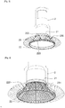
Fig. 3 ] est un pignon conique selon un premier mode de réalisation de l'invention ; - [
Fig. 4 ] est une variante du pignon de lafigure 3 ; - [
Fig. 5 ] est une coupe d'un engrenage à renvoi d'angle avec un dispositif de lubrification selon un deuxième mode de réalisation de l'invention ; - [
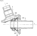
Fig. 6 ] montre le dispositif de lubrification de lafigure 5 ; - [
Fig. 7 ] est une première variante de lafigure 5 ; - [
Fig. 8 ] montre le dispositif de lubrification de lafigure 7 ; - [
Fig. 9 ] est une deuxième variante de lafigure 5 . - Sauf précision contraire, un même élément apparaissant sur des figures différentes présente une référence unique.
- L'engrenage 1 présenté sur les figures est une boite de transfert d'angle avec deux pignons coniques 2 et 3. Les deux pignons 2 et 3 sont creux.
- Le premier pignon 2 est d'axe X et ses dents 20 sont placées sur un cône dans le prolongement d'une paroi cylindrique 25 d'axe X.
- Le deuxième pignon 3 est d'axe Y et ses dents 30 sont placées à l'extérieur d'une paroi cylindrique 35 d'axe Y.
- Chaque pignon présente des dents 20 et 30 disposées sur le pourtour du pignon et inclinées respectivement par rapport à l'axe X et Y. Les dents 20 et 30 présentent également une courbure radiale.
- Les dents 20 et 30 s'engrenant les unes avec les autres un seul dispositif de lubrification est nécessaire pour les deux pignons. Il peut être situé indifféremment sur l'un ou l'autre des pignons.
- Aux
figures 1 à 4 , le dispositif de lubrification est disposé sur le pignon 2. Le pignon 2 comprend un rebord intérieur 21 sur lequel du lubrifiant 4 va s'accumuler pour servir d'arrivée dans le dispositif de lubrification. Le rebord 21 est percé de trous d'entrée 210 disposés axialement et reliés à une partie périphérique externe 22 par des conduits de distribution 23. La partie périphérique externe 22 est orientée avec une même inclinaison que les dents 20. - Le lubrifiant arrive selon la direction L dans le pignon 2 par un gicleur (non représenté), il va être plaqué sur les faces intérieures 24 du pignon 2 par la force centrifuge et va remplir la partie supérieure du rebord 21 constituant ainsi un réservoir 40.
- On peut voir sur la
figure 3 que le dispositif de lubrification forme un cône 230 continu circonférenciellement et percé de plusieurs conduits 23 reliant le rebord 21 à la partie périphérique 22. - La partie périphérique externe 22 comprend des trous de sortie 220 disposés axialement, orientés avec la même inclinaison que les dents et dans un creux 200 entre deux dents 20. Le nombre de trous d'entrée 210 est égal au nombre de trous de sortie 220. Le dispositif de lubrification constitue ainsi un gicleur.
- Dans la variante de la
figure 4 , le cône est constitué de plusieurs tubes 231 constituant des conduits 23 et espacés les uns des autres. Le nombre et la taille des tubes 231 varie en fonction du nombre de trous de sortie 220. Chacun des trous de sortie 220 est de préférence disposé en vis-à-vis d'un tube 231. - Dans le mode de réalisation illustré à la
figure 5 , le deuxième pignon 3 d'axe Y comprend une paroi cylindrique 35, d'axe Y, sur la face intérieur 350 de laquelle il y a deux rebords 31 et 32 qui vont permettre de garder du lubrifiant 4 à proximité des dents 30 et constituer ainsi un réservoir 40. La paroi cylindrique 35 comprend une face extérieure 351 sur laquelle sont placés en saillie les dents 30. Dans ce mode de réalisation, ces rebords 31 et 32 sont décalés par rapport aux dents 30. - La face intérieure 350 de la paroi 35 est percée de trous d'entrée 333 radiaux, disposés entre les deux rebords 31 et 32. Un cône 33 se terminant par une partie périphérique externe 34, relie les dents 30 aux trous d'entrée 333. Le cône 33 comprend une rainure périphérique 334 dans laquelle débouchent les trous d'entrée 333. Le cône 33 est percé de plusieurs conduits 330, chacun partant de la rainure périphérique 334 jusqu'à un trou de sortie 331, permettant l'amené du lubrifiant du réservoir 40 vers les dents 30. Les trous de sortie 331 sont placés entre deux dents 30.
- La rainure 334 permet de limiter le nombre de trous d'entrée 333 à percer dans la paroi 35. En effet la rainure permet une répartition du lubrifiant sur tout le pourtour du pignon 3. Le nombre de trous d'entrée 333 peut donc être inférieur au nombre de trous de sortie 331.
- Le nombre de trous d'entrée 333 peut aussi être égal au nombre de trous de sortie 331, dans ce cas la rainure périphérique 334 n'est pas nécessaire.
- Dans la première variante illustrée
figures 7 et 8 , le cône 33 desfigures 5 et 6 est remplacé par des tubes 36 répartis sur une surface conique correspondant à celle décrite par le cône 33. Le nombre de tubes 36 est égal au nombre de dents 30 et les tubes 36 sont placés en vis-à-vis d'un creux 300 entre deux dents 30. - La deuxième variante de la
figure 9 montre un dispositif de lubrification à double paroi. Dans cet exemple, le cône 33 est constitué de deux parois coniques 335 et 336 définissant un passage 337 pour le lubrifiant 4. Une des parois pourra comprendre des rainures du côté intérieur du passage 337 pour guider le lubrifiant. Les autres éléments sont identiques. - La fabrication de ce cône est simple, puisqu'il peut être réalisé avec des tôles embouties. Le cône décrit dans les exemples illustrés constitue une couronne qui peut avoir une forme différente.
- Nous allons maintenant décrire le mode de fonctionnement du dispositif de lubrification. Quand les pignons 2 et 3 sont en mouvement, un gicleur envoie du lubrifiant, tel que de l'huile, selon l'orientation de la flèche L à l'intérieur d'un des pignons 2 ou 3, leur rotation plaque le lubrifiant sur la face intérieure 24 ou 350 des parois 25 et 35. Les rebords 21, ou 31 et 32 vont retenir le lubrifiant dans le réservoir 40. La force centrifuge va pousser le lubrifiant dans les trous d'entrée 210 ou 333, puis dans les conduits 23 ou 330 et les trous de sortie 220 ou 331 pour aller ensuite graisser toute la longueur des creux 200 et 300 entre les dents 20 et 30. Le dispositif de lubrification tournant avec le pignon et les trous de sortie étant disposés directement entre les dents, il n'y a pas de « coupe » du jet, la quantité d'huile est donc fournit au juste nécessaire.
Claims (10)
- Pignon (2, 3) s'étendant autour d'un axe, comprenant un arbre et des dents (20, 30) portées par un voile qui s'étend autour de l'arbre et un dispositif de lubrification caractérisé en ce que le dispositif de lubrification forme une couronne séparée fixée à l'arbre avec une entrée d'huile côté arbre et une sortie d'huile côté denture d'engrènement et comprend une arrivée de lubrifiant en communication fluide avec un circuit de lubrification de l'arbre, le dispositif de lubrification comprenant des trous de sortie (220, 331) qui débouchent entre deux dents (20, 30) du pignon.
- Pignon (2, 3) selon la revendication 1, caractérisé en ce que les trous de sortie (220, 331) sont placés en vis-à-vis d'un creux (200, 300) entre deux dents (20, 30).
- Pignon (2, 3) selon la revendication précédente, caractérisé en ce que le nombre de trous de sortie (220, 331) est égal au nombre de creux (200, 300).
- Pignon (2, 3) selon une des revendications précédentes, caractérisé en ce que le pignon est conique.
- Pignon (2, 3) selon une des revendications précédentes, caractérisé en ce que le dispositif de lubrification est de forme conique avec une base qui comprend l'arrivée de lubrifiant et un sommet qui comprend les trous de sortie (220, 331) et dans lequel la base constitue une partie périphérique interne et le sommet constitue une partie périphérique externe (22, 34).
- Pignon (2, 3) selon une des revendications précédentes, caractérisé en ce que le dispositif de lubrification comprend plusieurs conduits de distribution séparés entre l'arrivée du lubrifiant et les trous de sortie (220, 331).
- Pignon (2, 3) selon une des revendications 1 à 5, caractérisé en ce que le dispositif de lubrification comprend une double paroi (335, 336) entre l'arrivée du lubrifiant et les trous de sortie (220, 331).
- Pignon (2, 3) selon la revendication précédente, caractérisé en ce qu'une des deux parois (335, 336) comprend des rainures.
- Pignon (2, 3) selon la revendication 4, caractérisé en ce que le dispositif de lubrification est disposé entre les dents du pignon et l'arbre du pignon.
- Dispositif d'engrènement de deux pignons comprenant au moins un pignon (2, 3) selon une des revendications précédentes.
Applications Claiming Priority (1)
| Application Number | Priority Date | Filing Date | Title |
|---|---|---|---|
| FR2004000A FR3109602B1 (fr) | 2020-04-22 | 2020-04-22 | Pignon avec un dispositif de lubrification |
Publications (2)
| Publication Number | Publication Date |
|---|---|
| EP3901422A1 true EP3901422A1 (fr) | 2021-10-27 |
| EP3901422B1 EP3901422B1 (fr) | 2024-04-10 |
Family
ID=71094575
Family Applications (1)
| Application Number | Title | Priority Date | Filing Date |
|---|---|---|---|
| EP21158475.0A Active EP3901422B1 (fr) | 2020-04-22 | 2021-02-22 | Pignon avec un dispositif de lubrification |
Country Status (2)
| Country | Link |
|---|---|
| EP (1) | EP3901422B1 (fr) |
| FR (1) | FR3109602B1 (fr) |
Citations (5)
| Publication number | Priority date | Publication date | Assignee | Title |
|---|---|---|---|---|
| FR896079A (fr) * | 1942-04-16 | 1945-02-12 | Audi Ag | Roue d'engrenage |
| DE1273914B (de) * | 1964-07-30 | 1968-07-25 | M A N Turbo G M B H | Schmiervorrichtung an einem Zahnrad |
| US3424022A (en) * | 1967-01-23 | 1969-01-28 | Babcock & Wilcox Co | Hydrostatic gearing |
| US20070175706A1 (en) * | 2006-01-30 | 2007-08-02 | Honeywell International, Inc. | Positive lubrication of a meshing gear |
| FR3055028A1 (fr) | 2016-08-11 | 2018-02-16 | Safran Transmission Systems | Dispositif d'engrenement pour turbomachine, turbomachine associee |
Family Cites Families (1)
| Publication number | Priority date | Publication date | Assignee | Title |
|---|---|---|---|---|
| US5622239A (en) * | 1995-07-14 | 1997-04-22 | A.T.S. Electro-Lube Holdings Ltd. | Gear wheel lubricator |
-
2020
- 2020-04-22 FR FR2004000A patent/FR3109602B1/fr active Active
-
2021
- 2021-02-22 EP EP21158475.0A patent/EP3901422B1/fr active Active
Patent Citations (5)
| Publication number | Priority date | Publication date | Assignee | Title |
|---|---|---|---|---|
| FR896079A (fr) * | 1942-04-16 | 1945-02-12 | Audi Ag | Roue d'engrenage |
| DE1273914B (de) * | 1964-07-30 | 1968-07-25 | M A N Turbo G M B H | Schmiervorrichtung an einem Zahnrad |
| US3424022A (en) * | 1967-01-23 | 1969-01-28 | Babcock & Wilcox Co | Hydrostatic gearing |
| US20070175706A1 (en) * | 2006-01-30 | 2007-08-02 | Honeywell International, Inc. | Positive lubrication of a meshing gear |
| FR3055028A1 (fr) | 2016-08-11 | 2018-02-16 | Safran Transmission Systems | Dispositif d'engrenement pour turbomachine, turbomachine associee |
Also Published As
| Publication number | Publication date |
|---|---|
| FR3109602B1 (fr) | 2023-03-24 |
| FR3109602A1 (fr) | 2021-10-29 |
| EP3901422B1 (fr) | 2024-04-10 |
Similar Documents
| Publication | Publication Date | Title |
|---|---|---|
| EP3710727B1 (fr) | Réducteur de vitesse a train planétaire ou épicycloïdal de turbomachine | |
| EP3350482B1 (fr) | Dispositif d'alimentation en huile pour un reducteur a train epicycloïdal | |
| EP3822516B1 (fr) | Rouet etage pour l'alimentation en huile d'un reducteur epicycloïdal ou planetaire | |
| FR3047279B1 (fr) | Rouet de distribution a repartition axiale et reducteur a train epicycloidal ainsi equipe | |
| EP3575562A1 (fr) | Systeme de transmission de puissance comprenant un dispositif de récupération d'huile de lubrification et turbomachine equipee d'un tel systeme de transmission de puissance | |
| EP3956555B1 (fr) | Reducteur de vitesse d'une turbomachine | |
| EP4058689B1 (fr) | Rouet pour un porte-satellites de reducteur de vitesse a train epicycloïdal de turbomachine | |
| EP3822515B1 (fr) | Rouet pour un porte-satellites de reducteur de vitesse à train epicycloïdal de turbomachine | |
| EP3677760B1 (fr) | Déflecteur pour le carenage d'un pignon de turbomachine, boitier d'engrenages et turbomachine associés | |
| EP3857029B1 (fr) | Reservoir auxiliaire d'huile pour une turbomachine d'aeronef | |
| WO2018189457A1 (fr) | Ensemble comprenant un train d'engrenages epicycloïdal | |
| EP3212898B1 (fr) | Capot de récupération d'huile de lubrification pour un équipement de turbomachine | |
| EP3901422B1 (fr) | Pignon avec un dispositif de lubrification | |
| EP3610177B1 (fr) | Train d'engrenages epicycloïdal | |
| FR3099220A1 (fr) | Réducteur de vitesse à train épicycloïdal pour une turbomachine | |
| EP3610175A1 (fr) | Lubrification pour train d'engrenages épicycloïdal | |
| WO2018029413A1 (fr) | Dispositif d'engrenement pour turbomachine, turbomachine associee | |
| EP4001703A1 (fr) | Pignon avec dispositif de lubrification | |
| EP3719267B1 (fr) | Gicleur pour turbomachine comprenant une tête d'éjection à face oblique | |
| FR3109603A1 (fr) | Pignon avec un dispositif de lubrification | |
| EP4722503A1 (fr) | Rouet de lubrification pour un reducteur de vitesse de turbomachine |
Legal Events
| Date | Code | Title | Description |
|---|---|---|---|
| PUAI | Public reference made under article 153(3) epc to a published international application that has entered the european phase |
Free format text: ORIGINAL CODE: 0009012 |
|
| STAA | Information on the status of an ep patent application or granted ep patent |
Free format text: STATUS: THE APPLICATION HAS BEEN PUBLISHED |
|
| AK | Designated contracting states |
Kind code of ref document: A1 Designated state(s): AL AT BE BG CH CY CZ DE DK EE ES FI FR GB GR HR HU IE IS IT LI LT LU LV MC MK MT NL NO PL PT RO RS SE SI SK SM TR |
|
| B565 | Issuance of search results under rule 164(2) epc |
Effective date: 20210806 |
|
| STAA | Information on the status of an ep patent application or granted ep patent |
Free format text: STATUS: REQUEST FOR EXAMINATION WAS MADE |
|
| 17P | Request for examination filed |
Effective date: 20211116 |
|
| RBV | Designated contracting states (corrected) |
Designated state(s): AL AT BE BG CH CY CZ DE DK EE ES FI FR GB GR HR HU IE IS IT LI LT LU LV MC MK MT NL NO PL PT RO RS SE SI SK SM TR |
|
| STAA | Information on the status of an ep patent application or granted ep patent |
Free format text: STATUS: EXAMINATION IS IN PROGRESS |
|
| 17Q | First examination report despatched |
Effective date: 20220816 |
|
| GRAP | Despatch of communication of intention to grant a patent |
Free format text: ORIGINAL CODE: EPIDOSNIGR1 |
|
| STAA | Information on the status of an ep patent application or granted ep patent |
Free format text: STATUS: GRANT OF PATENT IS INTENDED |
|
| INTG | Intention to grant announced |
Effective date: 20231103 |
|
| GRAS | Grant fee paid |
Free format text: ORIGINAL CODE: EPIDOSNIGR3 |
|
| GRAA | (expected) grant |
Free format text: ORIGINAL CODE: 0009210 |
|
| STAA | Information on the status of an ep patent application or granted ep patent |
Free format text: STATUS: THE PATENT HAS BEEN GRANTED |
|
| AK | Designated contracting states |
Kind code of ref document: B1 Designated state(s): AL AT BE BG CH CY CZ DE DK EE ES FI FR GB GR HR HU IE IS IT LI LT LU LV MC MK MT NL NO PL PT RO RS SE SI SK SM TR |
|
| REG | Reference to a national code |
Ref country code: GB Ref legal event code: FG4D Free format text: NOT ENGLISH |
|
| REG | Reference to a national code |
Ref country code: CH Ref legal event code: EP |
|
| REG | Reference to a national code |
Ref country code: DE Ref legal event code: R096 Ref document number: 602021011455 Country of ref document: DE |
|
| REG | Reference to a national code |
Ref country code: IE Ref legal event code: FG4D Free format text: LANGUAGE OF EP DOCUMENT: FRENCH |
|
| REG | Reference to a national code |
Ref country code: LT Ref legal event code: MG9D |
|
| REG | Reference to a national code |
Ref country code: NL Ref legal event code: MP Effective date: 20240410 |
|
| REG | Reference to a national code |
Ref country code: AT Ref legal event code: MK05 Ref document number: 1675106 Country of ref document: AT Kind code of ref document: T Effective date: 20240410 |
|
| PG25 | Lapsed in a contracting state [announced via postgrant information from national office to epo] |
Ref country code: NL Free format text: LAPSE BECAUSE OF FAILURE TO SUBMIT A TRANSLATION OF THE DESCRIPTION OR TO PAY THE FEE WITHIN THE PRESCRIBED TIME-LIMIT Effective date: 20240410 |
|
| PG25 | Lapsed in a contracting state [announced via postgrant information from national office to epo] |
Ref country code: NL Free format text: LAPSE BECAUSE OF FAILURE TO SUBMIT A TRANSLATION OF THE DESCRIPTION OR TO PAY THE FEE WITHIN THE PRESCRIBED TIME-LIMIT Effective date: 20240410 |
|
| PG25 | Lapsed in a contracting state [announced via postgrant information from national office to epo] |
Ref country code: IS Free format text: LAPSE BECAUSE OF FAILURE TO SUBMIT A TRANSLATION OF THE DESCRIPTION OR TO PAY THE FEE WITHIN THE PRESCRIBED TIME-LIMIT Effective date: 20240810 |
|
| PG25 | Lapsed in a contracting state [announced via postgrant information from national office to epo] |
Ref country code: BG Free format text: LAPSE BECAUSE OF FAILURE TO SUBMIT A TRANSLATION OF THE DESCRIPTION OR TO PAY THE FEE WITHIN THE PRESCRIBED TIME-LIMIT Effective date: 20240410 |
|
| PG25 | Lapsed in a contracting state [announced via postgrant information from national office to epo] |
Ref country code: HR Free format text: LAPSE BECAUSE OF FAILURE TO SUBMIT A TRANSLATION OF THE DESCRIPTION OR TO PAY THE FEE WITHIN THE PRESCRIBED TIME-LIMIT Effective date: 20240410 Ref country code: FI Free format text: LAPSE BECAUSE OF FAILURE TO SUBMIT A TRANSLATION OF THE DESCRIPTION OR TO PAY THE FEE WITHIN THE PRESCRIBED TIME-LIMIT Effective date: 20240410 |
|
| PG25 | Lapsed in a contracting state [announced via postgrant information from national office to epo] |
Ref country code: GR Free format text: LAPSE BECAUSE OF FAILURE TO SUBMIT A TRANSLATION OF THE DESCRIPTION OR TO PAY THE FEE WITHIN THE PRESCRIBED TIME-LIMIT Effective date: 20240711 |
|
| PG25 | Lapsed in a contracting state [announced via postgrant information from national office to epo] |
Ref country code: PT Free format text: LAPSE BECAUSE OF FAILURE TO SUBMIT A TRANSLATION OF THE DESCRIPTION OR TO PAY THE FEE WITHIN THE PRESCRIBED TIME-LIMIT Effective date: 20240812 |
|
| PG25 | Lapsed in a contracting state [announced via postgrant information from national office to epo] |
Ref country code: ES Free format text: LAPSE BECAUSE OF FAILURE TO SUBMIT A TRANSLATION OF THE DESCRIPTION OR TO PAY THE FEE WITHIN THE PRESCRIBED TIME-LIMIT Effective date: 20240410 |
|
| PG25 | Lapsed in a contracting state [announced via postgrant information from national office to epo] |
Ref country code: AT Free format text: LAPSE BECAUSE OF FAILURE TO SUBMIT A TRANSLATION OF THE DESCRIPTION OR TO PAY THE FEE WITHIN THE PRESCRIBED TIME-LIMIT Effective date: 20240410 |
|
| PG25 | Lapsed in a contracting state [announced via postgrant information from national office to epo] |
Ref country code: PL Free format text: LAPSE BECAUSE OF FAILURE TO SUBMIT A TRANSLATION OF THE DESCRIPTION OR TO PAY THE FEE WITHIN THE PRESCRIBED TIME-LIMIT Effective date: 20240410 |
|
| PG25 | Lapsed in a contracting state [announced via postgrant information from national office to epo] |
Ref country code: LV Free format text: LAPSE BECAUSE OF FAILURE TO SUBMIT A TRANSLATION OF THE DESCRIPTION OR TO PAY THE FEE WITHIN THE PRESCRIBED TIME-LIMIT Effective date: 20240410 |
|
| PG25 | Lapsed in a contracting state [announced via postgrant information from national office to epo] |
Ref country code: PT Free format text: LAPSE BECAUSE OF FAILURE TO SUBMIT A TRANSLATION OF THE DESCRIPTION OR TO PAY THE FEE WITHIN THE PRESCRIBED TIME-LIMIT Effective date: 20240812 Ref country code: PL Free format text: LAPSE BECAUSE OF FAILURE TO SUBMIT A TRANSLATION OF THE DESCRIPTION OR TO PAY THE FEE WITHIN THE PRESCRIBED TIME-LIMIT Effective date: 20240410 Ref country code: NO Free format text: LAPSE BECAUSE OF FAILURE TO SUBMIT A TRANSLATION OF THE DESCRIPTION OR TO PAY THE FEE WITHIN THE PRESCRIBED TIME-LIMIT Effective date: 20240710 Ref country code: LV Free format text: LAPSE BECAUSE OF FAILURE TO SUBMIT A TRANSLATION OF THE DESCRIPTION OR TO PAY THE FEE WITHIN THE PRESCRIBED TIME-LIMIT Effective date: 20240410 Ref country code: IS Free format text: LAPSE BECAUSE OF FAILURE TO SUBMIT A TRANSLATION OF THE DESCRIPTION OR TO PAY THE FEE WITHIN THE PRESCRIBED TIME-LIMIT Effective date: 20240810 Ref country code: HR Free format text: LAPSE BECAUSE OF FAILURE TO SUBMIT A TRANSLATION OF THE DESCRIPTION OR TO PAY THE FEE WITHIN THE PRESCRIBED TIME-LIMIT Effective date: 20240410 Ref country code: GR Free format text: LAPSE BECAUSE OF FAILURE TO SUBMIT A TRANSLATION OF THE DESCRIPTION OR TO PAY THE FEE WITHIN THE PRESCRIBED TIME-LIMIT Effective date: 20240711 Ref country code: FI Free format text: LAPSE BECAUSE OF FAILURE TO SUBMIT A TRANSLATION OF THE DESCRIPTION OR TO PAY THE FEE WITHIN THE PRESCRIBED TIME-LIMIT Effective date: 20240410 Ref country code: ES Free format text: LAPSE BECAUSE OF FAILURE TO SUBMIT A TRANSLATION OF THE DESCRIPTION OR TO PAY THE FEE WITHIN THE PRESCRIBED TIME-LIMIT Effective date: 20240410 Ref country code: BG Free format text: LAPSE BECAUSE OF FAILURE TO SUBMIT A TRANSLATION OF THE DESCRIPTION OR TO PAY THE FEE WITHIN THE PRESCRIBED TIME-LIMIT Effective date: 20240410 Ref country code: AT Free format text: LAPSE BECAUSE OF FAILURE TO SUBMIT A TRANSLATION OF THE DESCRIPTION OR TO PAY THE FEE WITHIN THE PRESCRIBED TIME-LIMIT Effective date: 20240410 Ref country code: RS Free format text: LAPSE BECAUSE OF FAILURE TO SUBMIT A TRANSLATION OF THE DESCRIPTION OR TO PAY THE FEE WITHIN THE PRESCRIBED TIME-LIMIT Effective date: 20240710 |
|
| REG | Reference to a national code |
Ref country code: DE Ref legal event code: R097 Ref document number: 602021011455 Country of ref document: DE |
|
| PG25 | Lapsed in a contracting state [announced via postgrant information from national office to epo] |
Ref country code: DK Free format text: LAPSE BECAUSE OF FAILURE TO SUBMIT A TRANSLATION OF THE DESCRIPTION OR TO PAY THE FEE WITHIN THE PRESCRIBED TIME-LIMIT Effective date: 20240410 |
|
| PG25 | Lapsed in a contracting state [announced via postgrant information from national office to epo] |
Ref country code: EE Free format text: LAPSE BECAUSE OF FAILURE TO SUBMIT A TRANSLATION OF THE DESCRIPTION OR TO PAY THE FEE WITHIN THE PRESCRIBED TIME-LIMIT Effective date: 20240410 |
|
| PG25 | Lapsed in a contracting state [announced via postgrant information from national office to epo] |
Ref country code: CZ Free format text: LAPSE BECAUSE OF FAILURE TO SUBMIT A TRANSLATION OF THE DESCRIPTION OR TO PAY THE FEE WITHIN THE PRESCRIBED TIME-LIMIT Effective date: 20240410 |
|
| PG25 | Lapsed in a contracting state [announced via postgrant information from national office to epo] |
Ref country code: RO Free format text: LAPSE BECAUSE OF FAILURE TO SUBMIT A TRANSLATION OF THE DESCRIPTION OR TO PAY THE FEE WITHIN THE PRESCRIBED TIME-LIMIT Effective date: 20240410 Ref country code: SK Free format text: LAPSE BECAUSE OF FAILURE TO SUBMIT A TRANSLATION OF THE DESCRIPTION OR TO PAY THE FEE WITHIN THE PRESCRIBED TIME-LIMIT Effective date: 20240410 |
|
| PG25 | Lapsed in a contracting state [announced via postgrant information from national office to epo] |
Ref country code: SM Free format text: LAPSE BECAUSE OF FAILURE TO SUBMIT A TRANSLATION OF THE DESCRIPTION OR TO PAY THE FEE WITHIN THE PRESCRIBED TIME-LIMIT Effective date: 20240410 |
|
| PG25 | Lapsed in a contracting state [announced via postgrant information from national office to epo] |
Ref country code: SM Free format text: LAPSE BECAUSE OF FAILURE TO SUBMIT A TRANSLATION OF THE DESCRIPTION OR TO PAY THE FEE WITHIN THE PRESCRIBED TIME-LIMIT Effective date: 20240410 Ref country code: SK Free format text: LAPSE BECAUSE OF FAILURE TO SUBMIT A TRANSLATION OF THE DESCRIPTION OR TO PAY THE FEE WITHIN THE PRESCRIBED TIME-LIMIT Effective date: 20240410 Ref country code: RO Free format text: LAPSE BECAUSE OF FAILURE TO SUBMIT A TRANSLATION OF THE DESCRIPTION OR TO PAY THE FEE WITHIN THE PRESCRIBED TIME-LIMIT Effective date: 20240410 Ref country code: EE Free format text: LAPSE BECAUSE OF FAILURE TO SUBMIT A TRANSLATION OF THE DESCRIPTION OR TO PAY THE FEE WITHIN THE PRESCRIBED TIME-LIMIT Effective date: 20240410 Ref country code: DK Free format text: LAPSE BECAUSE OF FAILURE TO SUBMIT A TRANSLATION OF THE DESCRIPTION OR TO PAY THE FEE WITHIN THE PRESCRIBED TIME-LIMIT Effective date: 20240410 Ref country code: CZ Free format text: LAPSE BECAUSE OF FAILURE TO SUBMIT A TRANSLATION OF THE DESCRIPTION OR TO PAY THE FEE WITHIN THE PRESCRIBED TIME-LIMIT Effective date: 20240410 |
|
| PG25 | Lapsed in a contracting state [announced via postgrant information from national office to epo] |
Ref country code: IT Free format text: LAPSE BECAUSE OF FAILURE TO SUBMIT A TRANSLATION OF THE DESCRIPTION OR TO PAY THE FEE WITHIN THE PRESCRIBED TIME-LIMIT Effective date: 20240410 |
|
| PLBE | No opposition filed within time limit |
Free format text: ORIGINAL CODE: 0009261 |
|
| STAA | Information on the status of an ep patent application or granted ep patent |
Free format text: STATUS: NO OPPOSITION FILED WITHIN TIME LIMIT |
|
| 26N | No opposition filed |
Effective date: 20250113 |
|
| PG25 | Lapsed in a contracting state [announced via postgrant information from national office to epo] |
Ref country code: SI Free format text: LAPSE BECAUSE OF FAILURE TO SUBMIT A TRANSLATION OF THE DESCRIPTION OR TO PAY THE FEE WITHIN THE PRESCRIBED TIME-LIMIT Effective date: 20240410 |
|
| PG25 | Lapsed in a contracting state [announced via postgrant information from national office to epo] |
Ref country code: SE Free format text: LAPSE BECAUSE OF FAILURE TO SUBMIT A TRANSLATION OF THE DESCRIPTION OR TO PAY THE FEE WITHIN THE PRESCRIBED TIME-LIMIT Effective date: 20240410 |
|
| PG25 | Lapsed in a contracting state [announced via postgrant information from national office to epo] |
Ref country code: MC Free format text: LAPSE BECAUSE OF FAILURE TO SUBMIT A TRANSLATION OF THE DESCRIPTION OR TO PAY THE FEE WITHIN THE PRESCRIBED TIME-LIMIT Effective date: 20240410 |
|
| REG | Reference to a national code |
Ref country code: CH Ref legal event code: PL |
|
| PG25 | Lapsed in a contracting state [announced via postgrant information from national office to epo] |
Ref country code: LU Free format text: LAPSE BECAUSE OF NON-PAYMENT OF DUE FEES Effective date: 20250222 |
|
| PG25 | Lapsed in a contracting state [announced via postgrant information from national office to epo] |
Ref country code: CH Free format text: LAPSE BECAUSE OF NON-PAYMENT OF DUE FEES Effective date: 20250228 |
|
| REG | Reference to a national code |
Ref country code: BE Ref legal event code: MM Effective date: 20250228 |
|
| PG25 | Lapsed in a contracting state [announced via postgrant information from national office to epo] |
Ref country code: BE Free format text: LAPSE BECAUSE OF NON-PAYMENT OF DUE FEES Effective date: 20250228 |
|
| PG25 | Lapsed in a contracting state [announced via postgrant information from national office to epo] |
Ref country code: IE Free format text: LAPSE BECAUSE OF NON-PAYMENT OF DUE FEES Effective date: 20250222 |
|
| PGFP | Annual fee paid to national office [announced via postgrant information from national office to epo] |
Ref country code: GB Payment date: 20260219 Year of fee payment: 6 |
|
| PGFP | Annual fee paid to national office [announced via postgrant information from national office to epo] |
Ref country code: DE Payment date: 20260217 Year of fee payment: 6 |
|
| PGFP | Annual fee paid to national office [announced via postgrant information from national office to epo] |
Ref country code: FR Payment date: 20260219 Year of fee payment: 6 |
|
| PG25 | Lapsed in a contracting state [announced via postgrant information from national office to epo] |
Ref country code: CY Free format text: LAPSE BECAUSE OF FAILURE TO SUBMIT A TRANSLATION OF THE DESCRIPTION OR TO PAY THE FEE WITHIN THE PRESCRIBED TIME-LIMIT Effective date: 20240410 |
|
| PG25 | Lapsed in a contracting state [announced via postgrant information from national office to epo] |
Ref country code: LT Free format text: LAPSE BECAUSE OF FAILURE TO SUBMIT A TRANSLATION OF THE DESCRIPTION OR TO PAY THE FEE WITHIN THE PRESCRIBED TIME-LIMIT Effective date: 20240410 |
|
| PG25 | Lapsed in a contracting state [announced via postgrant information from national office to epo] |
Ref country code: TR Free format text: LAPSE BECAUSE OF FAILURE TO SUBMIT A TRANSLATION OF THE DESCRIPTION OR TO PAY THE FEE WITHIN THE PRESCRIBED TIME-LIMIT Effective date: 20240410 |