EP3901042A1 - Flexible circuit card assembly with preformed undulations for surveillance system hinge assembly - Google Patents
Flexible circuit card assembly with preformed undulations for surveillance system hinge assembly Download PDFInfo
- Publication number
- EP3901042A1 EP3901042A1 EP21169941.8A EP21169941A EP3901042A1 EP 3901042 A1 EP3901042 A1 EP 3901042A1 EP 21169941 A EP21169941 A EP 21169941A EP 3901042 A1 EP3901042 A1 EP 3901042A1
- Authority
- EP
- European Patent Office
- Prior art keywords
- flexible circuit
- assembly
- circuit board
- hinge assembly
- display unit
- Prior art date
- Legal status (The legal status is an assumption and is not a legal conclusion. Google has not performed a legal analysis and makes no representation as to the accuracy of the status listed.)
- Withdrawn
Links
- 230000004913 activation Effects 0.000 claims description 19
- 239000000463 material Substances 0.000 claims description 12
- 238000005452 bending Methods 0.000 claims description 10
- 230000000694 effects Effects 0.000 claims description 8
- 239000011248 coating agent Substances 0.000 claims description 7
- 238000000576 coating method Methods 0.000 claims description 7
- 238000012544 monitoring process Methods 0.000 claims description 7
- 238000012545 processing Methods 0.000 claims description 6
- 230000001939 inductive effect Effects 0.000 claims description 5
- RYGMFSIKBFXOCR-UHFFFAOYSA-N Copper Chemical compound [Cu] RYGMFSIKBFXOCR-UHFFFAOYSA-N 0.000 description 6
- 229910052802 copper Inorganic materials 0.000 description 5
- 239000010949 copper Substances 0.000 description 5
- 238000013461 design Methods 0.000 description 4
- 230000000712 assembly Effects 0.000 description 3
- 238000000429 assembly Methods 0.000 description 3
- 230000003068 static effect Effects 0.000 description 3
- 230000000007 visual effect Effects 0.000 description 3
- 238000005253 cladding Methods 0.000 description 2
- 238000004891 communication Methods 0.000 description 2
- 230000001965 increasing effect Effects 0.000 description 2
- -1 polyethylene naphthalate Polymers 0.000 description 2
- 238000003825 pressing Methods 0.000 description 2
- 238000012546 transfer Methods 0.000 description 2
- 229910000881 Cu alloy Inorganic materials 0.000 description 1
- 239000004593 Epoxy Substances 0.000 description 1
- 229910000640 Fe alloy Inorganic materials 0.000 description 1
- 239000004812 Fluorinated ethylene propylene Substances 0.000 description 1
- 239000004952 Polyamide Substances 0.000 description 1
- 239000004642 Polyimide Substances 0.000 description 1
- 239000003522 acrylic cement Substances 0.000 description 1
- 230000009471 action Effects 0.000 description 1
- XAGFODPZIPBFFR-UHFFFAOYSA-N aluminium Chemical compound [Al] XAGFODPZIPBFFR-UHFFFAOYSA-N 0.000 description 1
- 229910052782 aluminium Inorganic materials 0.000 description 1
- 239000004760 aramid Substances 0.000 description 1
- 229920003235 aromatic polyamide Polymers 0.000 description 1
- DMFGNRRURHSENX-UHFFFAOYSA-N beryllium copper Chemical compound [Be].[Cu] DMFGNRRURHSENX-UHFFFAOYSA-N 0.000 description 1
- 230000005540 biological transmission Effects 0.000 description 1
- 239000011889 copper foil Substances 0.000 description 1
- 230000001419 dependent effect Effects 0.000 description 1
- 230000000881 depressing effect Effects 0.000 description 1
- 239000011888 foil Substances 0.000 description 1
- 238000010348 incorporation Methods 0.000 description 1
- 238000009413 insulation Methods 0.000 description 1
- 239000004973 liquid crystal related substance Substances 0.000 description 1
- 238000004519 manufacturing process Methods 0.000 description 1
- 239000000203 mixture Substances 0.000 description 1
- 238000012986 modification Methods 0.000 description 1
- 230000004048 modification Effects 0.000 description 1
- 230000007935 neutral effect Effects 0.000 description 1
- 229920009441 perflouroethylene propylene Polymers 0.000 description 1
- 229920003207 poly(ethylene-2,6-naphthalate) Polymers 0.000 description 1
- 229920002647 polyamide Polymers 0.000 description 1
- 229920000728 polyester Polymers 0.000 description 1
- 239000011112 polyethylene naphthalate Substances 0.000 description 1
- 229920001721 polyimide Polymers 0.000 description 1
- 229920000642 polymer Polymers 0.000 description 1
- 230000009467 reduction Effects 0.000 description 1
- 230000002441 reversible effect Effects 0.000 description 1
- 229920001169 thermoplastic Polymers 0.000 description 1
- 229920001187 thermosetting polymer Polymers 0.000 description 1
- 239000004416 thermosoftening plastic Substances 0.000 description 1
- 230000007704 transition Effects 0.000 description 1
Images


Classifications
-
- H—ELECTRICITY
- H05—ELECTRIC TECHNIQUES NOT OTHERWISE PROVIDED FOR
- H05K—PRINTED CIRCUITS; CASINGS OR CONSTRUCTIONAL DETAILS OF ELECTRIC APPARATUS; MANUFACTURE OF ASSEMBLAGES OF ELECTRICAL COMPONENTS
- H05K1/00—Printed circuits
- H05K1/02—Details
- H05K1/0277—Bendability or stretchability details
- H05K1/028—Bending or folding regions of flexible printed circuits
-
- B—PERFORMING OPERATIONS; TRANSPORTING
- B64—AIRCRAFT; AVIATION; COSMONAUTICS
- B64D—EQUIPMENT FOR FITTING IN OR TO AIRCRAFT; FLIGHT SUITS; PARACHUTES; ARRANGEMENT OR MOUNTING OF POWER PLANTS OR PROPULSION TRANSMISSIONS IN AIRCRAFT
- B64D43/00—Arrangements or adaptations of instruments
-
- B—PERFORMING OPERATIONS; TRANSPORTING
- B64—AIRCRAFT; AVIATION; COSMONAUTICS
- B64D—EQUIPMENT FOR FITTING IN OR TO AIRCRAFT; FLIGHT SUITS; PARACHUTES; ARRANGEMENT OR MOUNTING OF POWER PLANTS OR PROPULSION TRANSMISSIONS IN AIRCRAFT
- B64D45/00—Aircraft indicators or protectors not otherwise provided for
- B64D45/0015—Devices specially adapted for the protection against criminal attack, e.g. anti-hijacking systems
- B64D45/0051—Devices specially adapted for the protection against criminal attack, e.g. anti-hijacking systems by monitoring passengers or crew on aircraft
- B64D45/0053—Devices specially adapted for the protection against criminal attack, e.g. anti-hijacking systems by monitoring passengers or crew on aircraft using visual equipment, e.g. cameras
-
- H—ELECTRICITY
- H01—ELECTRIC ELEMENTS
- H01R—ELECTRICALLY-CONDUCTIVE CONNECTIONS; STRUCTURAL ASSOCIATIONS OF A PLURALITY OF MUTUALLY-INSULATED ELECTRICAL CONNECTING ELEMENTS; COUPLING DEVICES; CURRENT COLLECTORS
- H01R12/00—Structural associations of a plurality of mutually-insulated electrical connecting elements, specially adapted for printed circuits, e.g. printed circuit boards [PCB], flat or ribbon cables, or like generally planar structures, e.g. terminal strips, terminal blocks; Coupling devices specially adapted for printed circuits, flat or ribbon cables, or like generally planar structures; Terminals specially adapted for contact with, or insertion into, printed circuits, flat or ribbon cables, or like generally planar structures
- H01R12/50—Fixed connections
- H01R12/59—Fixed connections for flexible printed circuits, flat or ribbon cables or like structures
- H01R12/61—Fixed connections for flexible printed circuits, flat or ribbon cables or like structures connecting to flexible printed circuits, flat or ribbon cables or like structures
- H01R12/613—Fixed connections for flexible printed circuits, flat or ribbon cables or like structures connecting to flexible printed circuits, flat or ribbon cables or like structures by means of interconnecting elements
-
- H—ELECTRICITY
- H05—ELECTRIC TECHNIQUES NOT OTHERWISE PROVIDED FOR
- H05K—PRINTED CIRCUITS; CASINGS OR CONSTRUCTIONAL DETAILS OF ELECTRIC APPARATUS; MANUFACTURE OF ASSEMBLAGES OF ELECTRICAL COMPONENTS
- H05K1/00—Printed circuits
- H05K1/02—Details
- H05K1/11—Printed elements for providing electric connections to or between printed circuits
- H05K1/115—Via connections; Lands around holes or via connections
-
- H—ELECTRICITY
- H05—ELECTRIC TECHNIQUES NOT OTHERWISE PROVIDED FOR
- H05K—PRINTED CIRCUITS; CASINGS OR CONSTRUCTIONAL DETAILS OF ELECTRIC APPARATUS; MANUFACTURE OF ASSEMBLAGES OF ELECTRICAL COMPONENTS
- H05K1/00—Printed circuits
- H05K1/02—Details
- H05K1/03—Use of materials for the substrate
- H05K1/0313—Organic insulating material
-
- H—ELECTRICITY
- H05—ELECTRIC TECHNIQUES NOT OTHERWISE PROVIDED FOR
- H05K—PRINTED CIRCUITS; CASINGS OR CONSTRUCTIONAL DETAILS OF ELECTRIC APPARATUS; MANUFACTURE OF ASSEMBLAGES OF ELECTRICAL COMPONENTS
- H05K2201/00—Indexing scheme relating to printed circuits covered by H05K1/00
- H05K2201/01—Dielectrics
- H05K2201/0104—Properties and characteristics in general
- H05K2201/0129—Thermoplastic polymer, e.g. auto-adhesive layer; Shaping of thermoplastic polymer
-
- H—ELECTRICITY
- H05—ELECTRIC TECHNIQUES NOT OTHERWISE PROVIDED FOR
- H05K—PRINTED CIRCUITS; CASINGS OR CONSTRUCTIONAL DETAILS OF ELECTRIC APPARATUS; MANUFACTURE OF ASSEMBLAGES OF ELECTRICAL COMPONENTS
- H05K2201/00—Indexing scheme relating to printed circuits covered by H05K1/00
- H05K2201/01—Dielectrics
- H05K2201/0137—Materials
- H05K2201/0154—Polyimide
-
- H—ELECTRICITY
- H05—ELECTRIC TECHNIQUES NOT OTHERWISE PROVIDED FOR
- H05K—PRINTED CIRCUITS; CASINGS OR CONSTRUCTIONAL DETAILS OF ELECTRIC APPARATUS; MANUFACTURE OF ASSEMBLAGES OF ELECTRICAL COMPONENTS
- H05K2201/00—Indexing scheme relating to printed circuits covered by H05K1/00
- H05K2201/05—Flexible printed circuits [FPCs]
- H05K2201/057—Shape retainable
-
- H—ELECTRICITY
- H05—ELECTRIC TECHNIQUES NOT OTHERWISE PROVIDED FOR
- H05K—PRINTED CIRCUITS; CASINGS OR CONSTRUCTIONAL DETAILS OF ELECTRIC APPARATUS; MANUFACTURE OF ASSEMBLAGES OF ELECTRICAL COMPONENTS
- H05K2201/00—Indexing scheme relating to printed circuits covered by H05K1/00
- H05K2201/09—Shape and layout
- H05K2201/09209—Shape and layout details of conductors
- H05K2201/095—Conductive through-holes or vias
- H05K2201/09545—Plated through-holes or blind vias without lands
-
- H—ELECTRICITY
- H05—ELECTRIC TECHNIQUES NOT OTHERWISE PROVIDED FOR
- H05K—PRINTED CIRCUITS; CASINGS OR CONSTRUCTIONAL DETAILS OF ELECTRIC APPARATUS; MANUFACTURE OF ASSEMBLAGES OF ELECTRICAL COMPONENTS
- H05K2201/00—Indexing scheme relating to printed circuits covered by H05K1/00
- H05K2201/10—Details of components or other objects attached to or integrated in a printed circuit board
- H05K2201/10007—Types of components
- H05K2201/10128—Display
-
- H—ELECTRICITY
- H05—ELECTRIC TECHNIQUES NOT OTHERWISE PROVIDED FOR
- H05K—PRINTED CIRCUITS; CASINGS OR CONSTRUCTIONAL DETAILS OF ELECTRIC APPARATUS; MANUFACTURE OF ASSEMBLAGES OF ELECTRICAL COMPONENTS
- H05K3/00—Apparatus or processes for manufacturing printed circuits
- H05K3/40—Forming printed elements for providing electric connections to or between printed circuits
- H05K3/42—Plated through-holes or plated via connections
Definitions
- One area of focus is the ability of the flight and/or cabin crew, as well as other authorized personnel which may be present on the aircraft, to monitor the activities occurring within the passenger cabin (and/or cargo area) of an aircraft. Of particular importance is the ability to allow the flight crew to observe unusual or emergency activities by passengers on board the aircraft. Accordingly, there is a significant need for a surveillance system particularly structured to monitor the activities within predetermined portions of an aircraft such as, but not necessarily limited to, the passenger cabin.
- An example of such a surveillance system is a cockpit door surveillance system (CDSS) that aids a pilot in monitoring an area outside the cockpit door.
- CDSS cockpit door surveillance system
- the hinge assembly includes: a flexible circuit board having planar conductive circuitry and including at least one preformed undulation in a region of the flexible circuit board, wherein the at least one undulation is configured to allow the flexible circuit board to bend at the region; and a plurality of plated-through holes defined by the flexible circuit board, wherein the holes are configured to allow attachment of the flexible circuit board to the two objects, wherein the flexible circuit board is configured to movably and electrically connect the two objects.
- the display assembly includes: a display unit; and a hinge assembly including: a flexible circuit board having planar conductive circuitry and including at least one preformed undulation in a region of the flexible circuit board, wherein the at least one undulation is configured to allow the flexible circuit board to bend at the region; and a plurality of plated-through holes defined by the flexible circuit board, wherein the holes are configured to allow attachment of the flexible circuit board to the display unit and to a fixed component, wherein the flexible circuit board is configured to movably and electrically connect the display unit and the hinge assembly.
- a surveillance system for monitoring activity within an aircraft interior includes: a viewing assembly disposed within the aircraft interior and structured to monitor at least a predetermined portion thereof; a display assembly disposed within the aircraft interior and electrically connected to the viewing assembly, the display assembly including: a display unit; and a hinge assembly including: a flexible circuit board having planar conductive circuitry and including at least one preformed undulation in a region of the flexible circuit board, wherein the at least one undulation is configured to allow the flexible circuit board to bend at the region; and a plurality of plated-through holes defined by the flexible circuit board, wherein the holes are configured to allow attachment of the flexible circuit board to the display unit and to a fixed component; an activation assembly variably spaced at least in part from the viewing assembly and remotely operative to initiate observation of the aircraft interior; and a control assembly interconnecting the viewing assembly, the display assembly and the activation assembly, wherein the flexible circuit board is configured to movably and electrically connect the display unit to the control assembly.
- the surveillance system can be a cockpit door surveillance system (CDSS) that can aid a pilot or other airplane crew member in monitoring an area outside the cockpit door.
- the CDSS can include, for example, cameras, a central processing unit (CPU), and least one display unit with an attached hinge assembly.
- the hinge assembly can be configured and arranged to allow swiveling motion of the display unit for the pilot's convenience.
- the hinge assembly can include a flexible circuit card, or flexible circuit board, that forms an interface to transfer signals from the central processing unit and/or the cameras to the display unit.
- the flexible circuit card can be subjected to bending, for example, during the swiveling action of the display unit.
- the hinge assembly disclosed in the present disclosure provides a new design in which the flexible circuit card includes at least one preformed undulation or wave that can improve resistance to fatigue failure of the flexible circuit card.
- the flexible circuit card includes at least one preformed undulation or wave that can improve resistance to fatigue failure of the flexible circuit card.
- FIG. 1 is a schematic representation in perspective and partial cutaway showing the location of certain operational components of a surveillance system of the present disclosure on or within an aircraft 10.
- Surveillance system 12 is structured to provide visual monitoring of activities within predetermined portions of a commercial, or other aircraft, such as, for example, an area outside a cockpit door.
- FIG. 1 further shows an interior view of a cockpit 14 absent certain normal structures and features associated therewith, such as the seats for the flight crew, control panels and other operational equipment.
- Surveillance system 12 may be adaptable for all commercial and private aircraft including those configured to transport passengers, freight/cargo or both.
- surveillance system 12 is structured to allow visual observation and monitoring of predetermined portions of the aircraft interior including, but not limited to, an area outside the cockpit door, by the members of the flight crew located within the cockpit 14 without any member of the flight crew having to leave the flight deck or cockpit 14.
- Surveillance system 14 comprises viewing assembly 16 and includes at least one but preferably a plurality of cameras 18. As shown in FIG. 1 , plurality of cameras 18 are two in number. However, surveillance system 12 may be operative with one such camera 18 or more than two of such cameras 18 located strategically throughout the predetermined portion of the aircraft interior being monitored, such as the passenger cabin, and specifically an area in front of cockpit door 20. As demonstrated in FIG. 1 , both cameras 18 may be secured to and depend from ceiling portions of the passenger cabin interior.
- each of cameras 18 may be specifically designed for aircraft application.
- each camera 18 may include a light sensor assembly (not shown) that senses and triggers an infrared source such as a light emitting diode (LED), for example.
- the light sensor assembly may be further structured to convey image data in the form of captured images to the flight crew, within cockpit 14.
- Surveillance system 12 comprises display assembly 22 including at least one but preferably a plurality of monitors 24 and 26 disposed within cockpit 14 in clear view of all or particular members of the flight crew.
- Display monitor 24 may be located adjacent the position of a captain/pilot such that observation and access to display monitor 24 is present.
- display monitor 26 may be located in accessible, observable relation to a first officer/co-pilot.
- a single display monitor can be located within the cockpit 14 or alternatively a number of such display monitors 24 or 26 greater than two, dependent upon the size, configuration, etc. of cockpit 14 and/or the number of individuals associated with the flight crew.
- Display monitors 24 and 26, for example may display a real-time or frame image of an area within the cabin of the aircraft 10 as captured by cameras 18, for example.
- Display assembly 22 may be hingedly connected or moveably coupled to a wall, desk or other structure in the cockpit 14 using a hinge assembly 23.
- Each of display monitors 24 and 26 includes a display screen (not shown in FIG. 1 ), which may be in the form of a liquid crystal display (LCD) or other appropriate structure capable of projecting images thereon in both black and white and color.
- LCD liquid crystal display
- Each of display monitors 24 and 26 includes operational controls, such as, for example, brightness control, contrast control and color control. It should be apparent that a greater or lesser number of such controls may be provided.
- Activation assembly 30 (shown in FIG. 1 in cockpit 14, but capable of being located throughout aircraft 10) may be operational to be controlled by the one or more members of the flight crew and/or cabin crew. As such, activation assembly 30 is operative to selectively activate one or more cameras 18 of viewing assembly 16 and concurrently alert members of the flight crew, located within cockpit 14 that emergency or other activities within aircraft 10 should be visually monitored.
- Activation assembly 30 may include at least one receiver 32 located at any one of a plurality of appropriate locations throughout aircraft 10 such as, but not limited to, a position adjacent camera 18 of viewing assembly 16.
- Receiver 32 may be structured to be responsive, by means of wireless communication with at least one but preferably a plurality of transmitters (not shown).
- the plurality of transmitters may generate and communicate, through wireless transmission, an activation signal to receiver 32.
- the transmitters may activate cameras 18 and/or an alert assembly generally indicated as 40 located within cockpit 14 of aircraft 10.
- alert assembly 40 at least one signal device such as a signal light and/or sounding device may be mounted thereon so as to be clearly observable and/or in communication with at least one, but preferably all of the numbers of the flight crew occupying cockpit 14.
- control assembly 50 serves to interconnect the various operative components, as set forth herein, of viewing assembly 16, activation assembly 30, display assembly 22, hinge assembly 23, and alert assembly 40.
- Control assembly 50, activation assembly 30 and other operative components associated with the remainder of surveillance system 12 may be structured to be operationally isolated from the critical flight systems of aircraft 10 so as to not interfere with operation therewith during flight or other performance of aircraft 10.
- An interface computer (not shown) can also be included in surveillance system 12.
- activation assembly 30 and control assembly 50 are structured to be operationally isolated, meaning that their activation, operation, etc. will not interfere with the critical flight system associated with operation and performance of aircraft 10.
- FIG. 2 is a schematic representation in perspective and partial cutaway showing a display assembly 100, including display unit 101 and a hinge assembly 105, and flexible circuit card assembly 110, in accordance with the present disclosure that may be included in a surveillance system of the present disclosure.
- Display unit 101 can be movably and/or hingedly connected to a wall or desk or other structure or object (not shown).
- Display unit 101 can include display monitor 102, which includes display screen 104 for viewing real-time or frame images transmitted from cameras (such as cameras 18 in FIG. 1 ).
- Display monitor 102 can be any suitable viewing panel, which is capable of displaying real-time or frame images transferred from cameras and/or a computer processing unit (CPU).
- CPU computer processing unit
- Hinge assembly 105 can be connected to display unit 101 and can be used to position and/or adjust display unit 101 with respect to a user such as, for example, a pilot, in order to enhance user comfort, efficiency and effectiveness.
- Hinge assembly 105 can attach or connect to display unit 101 at display mount 106 using a pivot or joint.
- Hinge assembly 105 can include pivot, or rotatable, joint 108 in order to allow a swiveling motion of the display unit 101 for the pilot's convenience.
- Hinge assembly 105 can include any suitable pivot or joint to pivotably or rotatably connect to display unit 101
- Flexible circuit card assembly 110 can be at least partially housed or enclosed in pivot joint 108, and can be connected on one side to display mount 106 and on an opposite side can be connected to hinge assembly 105, for example, using suitable fasteners at fastener locations 118. Flexible circuit card assembly 110 forms an interface to transfer signals from a CPU, for example, through hinge assembly 105 and to display unit 101.
- Hinge assembly 105 can also include hinge plate 120 that can be connected to pivot joint 108 on one side and to wall bracket 114 on an opposite side.
- Wall bracket 114 can include openings 116 for stationary attachment, using a fastener, to a wall, desk or other structure.
- Flexible circuit card assembly 110 can include a flexible base material and a conductive coating or cladding.
- Exemplary materials for the flexible base material can include thermoplastic, thermoset, polyamide, polyester, polyethylene naphthalate, fluorinated ethylenepropylene copolymer, polyetheride, aramid, and epoxy.
- Exemplary conductive coating or cladding materials includes copper foil, electrodeposited copper, rolled and annealed copper, specialty copper alloys, electroplated copper, sputtered or vapor deposited copper, beryllium copper, aluminum foil, iron alloy, or polymer thick film.
- a coverlay/insulation layer can be laminated over a copper coating or layer by pressing under heat, pressure and vacuum to ensure proper adhesion. Autoclave may be used.
- a mold having a wave design may be used, to introduce undulations or waves, during the pressing step.
- the flexible circuit card assembly 110 can be prebaked at about 120 degrees Celsius, with a duration of the pre-bake depending upon a layer count in the flexible circuit card assembly 110.
- the invention is not limited to any of the materials or the provided method of fabricating the flexible circuit card assembly 110 as disclosed herein.
- Flexible circuit card assembly 110 is configured and arranged to allow display unit 100 to be movably and/or hingedly connected to a wall or some other structure, and still allow a signal interface between a remote CPU, for example, through hinge assembly 105 and to display unit 101.
- Flexible circuit card assembly 110 includes at least one preformed undulation 112 or wave in a bend region 124, which can provide localized stress relief in bend region 124 (otherwise known as stress relief region) to reduce fatigue of flexible circuit hinge assembly 110 that can result from overuse or repeated flexing.
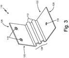
- FIG. 3 is a schematic representation in perspective of a flexible circuit card hinge 110 of the present disclosure, shown with a bend.
- Flexible circuit card assembly 110 can be configured and arranged to improve fatigue life. Flexible circuit card assemblies, when subjected to repeated bending loads, for example, can experience stress due to concave-convex transitions during repeated bending operations. One or more undulations 112 or waves can absorb bending stress. Flexible circuit card assembly 110 can have a uniform or generally uniform thickness. Flexible circuit card assembly 110 in FIGS. 2 and 3 is shown with two undulations 112 or waves. Other numbers of undulations 112, or bend regions 124 including undulations 112, are also contemplated.
- Undulations 112 are configured and arranged to allow flexibility at the region of the flexible circuit card assembly 110 including undulations 112 rather than inducing high stresses at fastener locations 118. At least one undulation 112 can be located or arranged symmetric about a neutral line of bending region 124 of flexible circuit card assembly 110.
- the size of undulations 112 can depend upon the material composition and thickness of flexible circuit card assembly 110. As an example, if a bend radius of a flexible circuit card (with no undulations) is "R," fatigue life of flexible circuit card assembly 110 can be increased by including undulations 112. The presence of more than two undulations 112, for example, in bend region 124, can result in the bend radii of undulations 112 being approximately 0.3R to approximately 0.6R.
- Fastener locations 118 (or plated-through holes) in flexible circuit card assembly 110 can have any suitable location or be present in any suitable number. Three fastener locations 118 are shown in FIG. 3 . Fastener locations 118 are not visible in FIG. 2 but are used to fasten flexible card circuit assembly 110 to rotatable component 107 at one end and wall bracket 114 at another, opposite end. FIG. 3 shows fastener locations 118 near a first end 126 of flexible circuit card assembly 110 and one fastener location 118 near a second end 128 of flexible circuit card assembly 110. Suitable fasteners can be used in fastener locations 118 to attach flexible circuit card assembly 110 to display unit 100 and wall bracket 114, for example.
- Flexible circuit card assembly 110 includes signal traces (not shown).
- the signal traces allow an electrical signal from an interface computer, for example, to be transferred to display unit 100. Bending stress on such signal traces can result in failure of flexible circuit card assembly 110. Undulations 112 reduce stress on the signal traces in flexible circuit card assembly 110.
- Flexible circuit card assembly 110 was made of three layers of polyimide attached with acrylic adhesive and having a total thickness of about 0.05 inch (1.27mm), as shown in bent configuration in FIG. 3 .
- Two preformed undulations 112 were formed in bend region 124, each undulation 112 having a radius as indicated of 0.075 inch (1.905 mm).
- Vertical face 120 was oriented about 90 degrees from, or perpendicular to, horizontal face 122.
- Vertical face 120 was 1.33 inches (33.78 mm) in length from bend region 124 to vertical edge 126.
- Vertical edge had a width of 2.0 inches (50.8 mm).
- Fastener locations (or holes) 118 on vertical face 120 were located 0.389 inch (9.88 mm) from vertical edge 126 and were used to constrain vertical face 120 during static analysis.
- Horizontal face 122 was 1.33 inches (33.78 mm) in length from bend region 124 to horizontal edge 128 and fastener location (or hole) 118 was located 0.665 inch (16.89 mm) from horizontal edge 128. Horizontal edge had a width of 2.0 inches (50.8 mm). The diameter of fastener location 118 in horizontal face 122 was 0.0176 inch (0.447 mm). During static analysis, horizontal face 122 was loaded, such that flexible circuit card assembly 110 deformed at bend region 124.
- the maximum principal stress at bend region 124 was measured at 0.62ksi for flexible circuit card assembly 110 as shown in FIGS. 2 and 3 , including undulations 112. Without the undulations 112, and with a bend such as that in FIG. 3 , the maximum principal stress was measured at 0.84 ksi. The maximum principal stress was found to be 26.2% lower for the flexible circuit card assembly design shown in FIGS. 2 and 3 compared to a flexible circuit card (or flexible circuit board) that was generally planar in configuration (before being bent) and that did not include preformed undulations or waves. We believe that such a reduction in stress is directly attributable to the incorporation of undulations 112 in the design and that similar benefits would be observed regardless of the materials used to construct a similar hinge, or flexible circuit card assembly.
- a hinge assembly configured for attachment to two objects may include: a flexible circuit board having planar conductive circuitry and including at least one preformed undulation in a region of the flexible circuit board, wherein the at least one undulation is configured to allow the flexible circuit board to bend at the region; and a plurality of plated-through holes defined by the flexible circuit board, wherein the holes are configured to allow attachment of the flexible circuit board to the two objects, wherein the flexible circuit board is configured to movably and electrically connect the two objects.
- the assembly of the preceding paragraph can optionally include, additionally and/or alternatively, any one or more of the following features, configurations and/or additional components:
- the at least one preformed undulation in the region may form a stress relief region in the flexible circuit board configured to reduce stress induced when bending the flexible circuit board.
- the at least one preformed undulation may be located between at least one of the plurality of plated-through holes located near a first end of the hinge assembly and at least one of the plurality of plated-through holes located near a second end of the hinge assembly.
- the at least one preformed undulation may be configured and arranged to allow flexibility at the region of the flexible circuit board including undulations rather than inducing high stresses at areas including the plurality of plated-through holes.
- the flexible circuit board may include a flexible base material and a conductive coating.
- the flexible circuit board may include at least two undulations.
- a display assembly may include: a display unit; and a hinge assembly including: a flexible circuit board having planar conductive circuitry and including at least one preformed undulation in a region of the flexible circuit board, wherein the at least one undulation is configured to allow the flexible circuit board to bend at the region; and a plurality of plated-through holes defined by the flexible circuit board, wherein the holes are configured to allow attachment of the flexible circuit board to the display unit and to a fixed component, wherein the flexible circuit board is configured to movably and electrically connect the display unit and the hinge assembly.
- the assembly of the preceding paragraph can optionally include, additionally and/or alternatively, any one or more of the following features, configurations and/or additional components:
- the at least one preformed undulation in the region may form a stress relief region in the flexible circuit board configured to reduce stress induced when bending the flexible circuit board.
- the assembly may further include a rotatable component between the display unit and the hinge assembly and configured to allow the display unit to pivot with respect to the flexible circuit board and the fixed component.
- the flexible circuit board may be configured to electrically connect the display unit, the hinge assembly and a remote computer processing unit.
- the at least one preformed undulation may be located between at least one of the plurality of plated-through holes located near a first end of the hinge assembly and at least one of the plurality of plated-through holes located near a second end of the hinge assembly.
- the at least one preformed undulation may be configured and arranged to allow flexibility at the region of the flexible circuit board including undulations rather than inducing high stresses at areas including the plurality of plated-through holes.
- the flexible circuit board may include a flexible base material and a conductive coating.
- the flexible circuit board may include at least two undulations.
- a surveillance system for monitoring activity within an aircraft interior includes: a viewing assembly disposed within the aircraft interior and structured to monitor at least a predetermined portion thereof; a display assembly disposed within the aircraft interior and electrically connected to the viewing assembly, the display assembly including: a display unit; and a hinge assembly including: a flexible circuit board having planar conductive circuitry and including at least one preformed undulation in a region of the flexible circuit board, wherein the at least one undulation is configured to allow the flexible circuit board to bend at the region; and a plurality of plated-through holes defined by the flexible circuit board, wherein the holes are configured to allow attachment of the flexible circuit board to the display unit and to a fixed component; an activation assembly variably spaced at least in part from the viewing assembly and remotely operative to initiate observation of the aircraft interior; and a control assembly interconnecting the viewing assembly, the display assembly and the activation assembly, wherein the flexible circuit board is configured to movably and electrically connect the display unit to the control assembly.
- the system of the preceding paragraph can optionally include, additionally and/or alternatively, any one or more of the following features, configurations and/or additional components:
- the at least one preformed undulation in the region may form a stress relief region in the flexible circuit board configured to reduce stress induced when bending the flexible circuit board.
- the at least one preformed undulation may be located between at least one of the plurality of plated-through holes located near a first end of the hinge assembly and at least one of the plurality of plated-through holes located near a second end of the hinge assembly.
- the at least one preformed undulation may be configured and arranged to allow flexibility at the region of the flexible circuit board including undulations rather than inducing high stresses at areas including the plurality of plated-through holes.
- the flexible circuit board may include a flexible base material and a conductive coating.
- the flexible circuit board may include at least two undulations.
Landscapes
- Engineering & Computer Science (AREA)
- Aviation & Aerospace Engineering (AREA)
- Microelectronics & Electronic Packaging (AREA)
- Structure Of Printed Boards (AREA)
Abstract
Description
- Over time, security has become a subject of increasing concern. One area of particular importance relates to the travel industry which involves processing millions of people on a daily basis. Air travel has received particular scrutiny and is the subject of attempts to greatly increase security measures in order to avoid emergency situations of the type set forth above, resulting in the death of thousands of people.
- One area of focus is the ability of the flight and/or cabin crew, as well as other authorized personnel which may be present on the aircraft, to monitor the activities occurring within the passenger cabin (and/or cargo area) of an aircraft. Of particular importance is the ability to allow the flight crew to observe unusual or emergency activities by passengers on board the aircraft. Accordingly, there is a significant need for a surveillance system particularly structured to monitor the activities within predetermined portions of an aircraft such as, but not necessarily limited to, the passenger cabin. An example of such a surveillance system is a cockpit door surveillance system (CDSS) that aids a pilot in monitoring an area outside the cockpit door.
- A hinge assembly configured for attachment to two objects is described herein. The hinge assembly includes: a flexible circuit board having planar conductive circuitry and including at least one preformed undulation in a region of the flexible circuit board, wherein the at least one undulation is configured to allow the flexible circuit board to bend at the region; and a plurality of plated-through holes defined by the flexible circuit board, wherein the holes are configured to allow attachment of the flexible circuit board to the two objects, wherein the flexible circuit board is configured to movably and electrically connect the two objects.
- A display assembly is described herein. The display assembly includes: a display unit; and a hinge assembly including: a flexible circuit board having planar conductive circuitry and including at least one preformed undulation in a region of the flexible circuit board, wherein the at least one undulation is configured to allow the flexible circuit board to bend at the region; and a plurality of plated-through holes defined by the flexible circuit board, wherein the holes are configured to allow attachment of the flexible circuit board to the display unit and to a fixed component, wherein the flexible circuit board is configured to movably and electrically connect the display unit and the hinge assembly.
- A surveillance system for monitoring activity within an aircraft interior is described herein. The system includes: a viewing assembly disposed within the aircraft interior and structured to monitor at least a predetermined portion thereof; a display assembly disposed within the aircraft interior and electrically connected to the viewing assembly, the display assembly including: a display unit; and a hinge assembly including: a flexible circuit board having planar conductive circuitry and including at least one preformed undulation in a region of the flexible circuit board, wherein the at least one undulation is configured to allow the flexible circuit board to bend at the region; and a plurality of plated-through holes defined by the flexible circuit board, wherein the holes are configured to allow attachment of the flexible circuit board to the display unit and to a fixed component; an activation assembly variably spaced at least in part from the viewing assembly and remotely operative to initiate observation of the aircraft interior; and a control assembly interconnecting the viewing assembly, the display assembly and the activation assembly, wherein the flexible circuit board is configured to movably and electrically connect the display unit to the control assembly.
-
-
FIG. 1 is a schematic representation in perspective and partial cutaway showing the location of certain operational components of a surveillance system on or within an aircraft in accordance with the present disclosure; -
FIG. 2 is a schematic representation in perspective and partial cutaway showing a display assembly in accordance with the present disclosure; and -
FIG. 3 is a schematic representation in perspective showing a flexible circuit card assembly in a bent configuration in accordance with the present disclosure. - An improved hinge assembly for a surveillance system, such as a surveillance system for an aircraft, is disclosed herein. The surveillance system can be a cockpit door surveillance system (CDSS) that can aid a pilot or other airplane crew member in monitoring an area outside the cockpit door. The CDSS can include, for example, cameras, a central processing unit (CPU), and least one display unit with an attached hinge assembly. The hinge assembly can be configured and arranged to allow swiveling motion of the display unit for the pilot's convenience. The hinge assembly can include a flexible circuit card, or flexible circuit board, that forms an interface to transfer signals from the central processing unit and/or the cameras to the display unit. The flexible circuit card can be subjected to bending, for example, during the swiveling action of the display unit. The hinge assembly disclosed in the present disclosure provides a new design in which the flexible circuit card includes at least one preformed undulation or wave that can improve resistance to fatigue failure of the flexible circuit card. A person of ordinary skill would recognize that other embodiments could be used in other aircraft and non-aircraft applications. Without limiting the broad scope of this disclosure, this disclosure will describe the CDSS embodiment.
-
FIG. 1 is a schematic representation in perspective and partial cutaway showing the location of certain operational components of a surveillance system of the present disclosure on or within anaircraft 10.Surveillance system 12 is structured to provide visual monitoring of activities within predetermined portions of a commercial, or other aircraft, such as, for example, an area outside a cockpit door.FIG. 1 further shows an interior view of acockpit 14 absent certain normal structures and features associated therewith, such as the seats for the flight crew, control panels and other operational equipment.Surveillance system 12 may be adaptable for all commercial and private aircraft including those configured to transport passengers, freight/cargo or both. Accordingly,surveillance system 12 is structured to allow visual observation and monitoring of predetermined portions of the aircraft interior including, but not limited to, an area outside the cockpit door, by the members of the flight crew located within thecockpit 14 without any member of the flight crew having to leave the flight deck orcockpit 14. -
Surveillance system 14 comprisesviewing assembly 16 and includes at least one but preferably a plurality ofcameras 18. As shown inFIG. 1 , plurality ofcameras 18 are two in number. However,surveillance system 12 may be operative with onesuch camera 18 or more than two ofsuch cameras 18 located strategically throughout the predetermined portion of the aircraft interior being monitored, such as the passenger cabin, and specifically an area in front ofcockpit door 20. As demonstrated inFIG. 1 , bothcameras 18 may be secured to and depend from ceiling portions of the passenger cabin interior. - In order to facilitate visual observation and image capturing during all flight conditions, each of
cameras 18 may be specifically designed for aircraft application. As such eachcamera 18 may include a light sensor assembly (not shown) that senses and triggers an infrared source such as a light emitting diode (LED), for example. The light sensor assembly may be further structured to convey image data in the form of captured images to the flight crew, withincockpit 14. -
Surveillance system 12 comprisesdisplay assembly 22 including at least one but preferably a plurality ofmonitors cockpit 14 in clear view of all or particular members of the flight crew.Display monitor 24 may be located adjacent the position of a captain/pilot such that observation and access todisplay monitor 24 is present. Similarly,display monitor 26 may be located in accessible, observable relation to a first officer/co-pilot. A single display monitor can be located within thecockpit 14 or alternatively a number ofsuch display monitors cockpit 14 and/or the number of individuals associated with the flight crew.Display monitors aircraft 10 as captured bycameras 18, for example.Display assembly 22 may be hingedly connected or moveably coupled to a wall, desk or other structure in thecockpit 14 using ahinge assembly 23. - Each of
display monitors FIG. 1 ), which may be in the form of a liquid crystal display (LCD) or other appropriate structure capable of projecting images thereon in both black and white and color. Each ofdisplay monitors - Yet another feature of
surveillance system 12 includesactivation assembly 30. Activation assembly 30 (shown inFIG. 1 incockpit 14, but capable of being located throughout aircraft 10) may be operational to be controlled by the one or more members of the flight crew and/or cabin crew. As such,activation assembly 30 is operative to selectively activate one ormore cameras 18 ofviewing assembly 16 and concurrently alert members of the flight crew, located withincockpit 14 that emergency or other activities withinaircraft 10 should be visually monitored. -
Activation assembly 30 may include at least onereceiver 32 located at any one of a plurality of appropriate locations throughoutaircraft 10 such as, but not limited to, a positionadjacent camera 18 ofviewing assembly 16.Receiver 32 may be structured to be responsive, by means of wireless communication with at least one but preferably a plurality of transmitters (not shown). The plurality of transmitters may generate and communicate, through wireless transmission, an activation signal toreceiver 32. The transmitters may activatecameras 18 and/or an alert assembly generally indicated as 40 located withincockpit 14 ofaircraft 10. With reference toalert assembly 40, at least one signal device such as a signal light and/or sounding device may be mounted thereon so as to be clearly observable and/or in communication with at least one, but preferably all of the numbers of the flightcrew occupying cockpit 14. In operation the occurrence of an emergency event worthy of being monitored by the flight crew withincockpit 14 will determine activation ofsurveillance system 12 of as one or more individuals of the flight and/or cabin crew manually depress, or otherwise manipulate,activation assembly 30. Depressing an activation button for at least one second may cause an activation signal to be transmitted toreceiver 32.Receiver 32 is connected bycontrol assembly 50 to other operative components and assemblies definingsurveillance system 12. More specifically,control assembly 50 may include electrical conduit or other appropriate electrical harness structures, and may be preferably mounted on interior, non-observable portions of the airframe ofaircraft 10. Accordingly,control assembly 50 serves to interconnect the various operative components, as set forth herein, ofviewing assembly 16,activation assembly 30,display assembly 22,hinge assembly 23, andalert assembly 40.Control assembly 50,activation assembly 30 and other operative components associated with the remainder ofsurveillance system 12 may be structured to be operationally isolated from the critical flight systems ofaircraft 10 so as to not interfere with operation therewith during flight or other performance ofaircraft 10. An interface computer (not shown) can also be included insurveillance system 12. - It should be noted that the structural and operational features of all of the components and assemblies, particularly including
activation assembly 30 andcontrol assembly 50, are structured to be operationally isolated, meaning that their activation, operation, etc. will not interfere with the critical flight system associated with operation and performance ofaircraft 10. -
FIG. 2 is a schematic representation in perspective and partial cutaway showing adisplay assembly 100, includingdisplay unit 101 and ahinge assembly 105, and flexiblecircuit card assembly 110, in accordance with the present disclosure that may be included in a surveillance system of the present disclosure.Display unit 101 can be movably and/or hingedly connected to a wall or desk or other structure or object (not shown).Display unit 101 can includedisplay monitor 102, which includesdisplay screen 104 for viewing real-time or frame images transmitted from cameras (such ascameras 18 inFIG. 1 ). Display monitor 102 can be any suitable viewing panel, which is capable of displaying real-time or frame images transferred from cameras and/or a computer processing unit (CPU). -
Hinge assembly 105 can be connected to displayunit 101 and can be used to position and/or adjustdisplay unit 101 with respect to a user such as, for example, a pilot, in order to enhance user comfort, efficiency and effectiveness.Hinge assembly 105 can attach or connect to displayunit 101 atdisplay mount 106 using a pivot or joint.Hinge assembly 105 can include pivot, or rotatable, joint 108 in order to allow a swiveling motion of thedisplay unit 101 for the pilot's convenience.Hinge assembly 105 can include any suitable pivot or joint to pivotably or rotatably connect to displayunit 101 - Flexible
circuit card assembly 110, described in more detail below, can be at least partially housed or enclosed in pivot joint 108, and can be connected on one side to displaymount 106 and on an opposite side can be connected to hingeassembly 105, for example, using suitable fasteners atfastener locations 118. Flexiblecircuit card assembly 110 forms an interface to transfer signals from a CPU, for example, throughhinge assembly 105 and to displayunit 101. -
Hinge assembly 105 can also includehinge plate 120 that can be connected to pivot joint 108 on one side and to wallbracket 114 on an opposite side.Wall bracket 114 can includeopenings 116 for stationary attachment, using a fastener, to a wall, desk or other structure. - Flexible
circuit card assembly 110 can include a flexible base material and a conductive coating or cladding. Exemplary materials for the flexible base material can include thermoplastic, thermoset, polyamide, polyester, polyethylene naphthalate, fluorinated ethylenepropylene copolymer, polyetheride, aramid, and epoxy. Exemplary conductive coating or cladding materials includes copper foil, electrodeposited copper, rolled and annealed copper, specialty copper alloys, electroplated copper, sputtered or vapor deposited copper, beryllium copper, aluminum foil, iron alloy, or polymer thick film. A coverlay/insulation layer can be laminated over a copper coating or layer by pressing under heat, pressure and vacuum to ensure proper adhesion. Autoclave may be used. A mold having a wave design may be used, to introduce undulations or waves, during the pressing step. The flexiblecircuit card assembly 110 can be prebaked at about 120 degrees Celsius, with a duration of the pre-bake depending upon a layer count in the flexiblecircuit card assembly 110. The invention, however, is not limited to any of the materials or the provided method of fabricating the flexiblecircuit card assembly 110 as disclosed herein. - Flexible
circuit card assembly 110 is configured and arranged to allowdisplay unit 100 to be movably and/or hingedly connected to a wall or some other structure, and still allow a signal interface between a remote CPU, for example, throughhinge assembly 105 and to displayunit 101. Flexiblecircuit card assembly 110 includes at least onepreformed undulation 112 or wave in abend region 124, which can provide localized stress relief in bend region 124 (otherwise known as stress relief region) to reduce fatigue of flexiblecircuit hinge assembly 110 that can result from overuse or repeated flexing. -
FIG. 3 is a schematic representation in perspective of a flexiblecircuit card hinge 110 of the present disclosure, shown with a bend. Flexiblecircuit card assembly 110 can be configured and arranged to improve fatigue life. Flexible circuit card assemblies, when subjected to repeated bending loads, for example, can experience stress due to concave-convex transitions during repeated bending operations. One ormore undulations 112 or waves can absorb bending stress. Flexiblecircuit card assembly 110 can have a uniform or generally uniform thickness. Flexiblecircuit card assembly 110 inFIGS. 2 and3 is shown with twoundulations 112 or waves. Other numbers ofundulations 112, or bendregions 124 includingundulations 112, are also contemplated.Undulations 112 are configured and arranged to allow flexibility at the region of the flexiblecircuit card assembly 110 includingundulations 112 rather than inducing high stresses atfastener locations 118. At least oneundulation 112 can be located or arranged symmetric about a neutral line of bendingregion 124 of flexiblecircuit card assembly 110. - The size of
undulations 112 can depend upon the material composition and thickness of flexiblecircuit card assembly 110. As an example, if a bend radius of a flexible circuit card (with no undulations) is "R," fatigue life of flexiblecircuit card assembly 110 can be increased by includingundulations 112. The presence of more than twoundulations 112, for example, inbend region 124, can result in the bend radii ofundulations 112 being approximately 0.3R to approximately 0.6R. - Fastener locations 118 (or plated-through holes) in flexible
circuit card assembly 110 can have any suitable location or be present in any suitable number. Threefastener locations 118 are shown inFIG. 3 .Fastener locations 118 are not visible inFIG. 2 but are used to fasten flexiblecard circuit assembly 110 to rotatable component 107 at one end andwall bracket 114 at another, opposite end.FIG. 3 showsfastener locations 118 near afirst end 126 of flexiblecircuit card assembly 110 and onefastener location 118 near asecond end 128 of flexiblecircuit card assembly 110. Suitable fasteners can be used infastener locations 118 to attach flexiblecircuit card assembly 110 to displayunit 100 andwall bracket 114, for example. - Flexible
circuit card assembly 110 includes signal traces (not shown). The signal traces allow an electrical signal from an interface computer, for example, to be transferred todisplay unit 100. Bending stress on such signal traces can result in failure of flexiblecircuit card assembly 110.Undulations 112 reduce stress on the signal traces in flexiblecircuit card assembly 110. - Static analysis was performed on one exemplary flexible
circuit card assembly 110, as shown inFIG. 3 . Flexiblecircuit card assembly 110 was made of three layers of polyimide attached with acrylic adhesive and having a total thickness of about 0.05 inch (1.27mm), as shown in bent configuration inFIG. 3 . Two preformedundulations 112 were formed inbend region 124, eachundulation 112 having a radius as indicated of 0.075 inch (1.905 mm). -
Vertical face 120 was oriented about 90 degrees from, or perpendicular to,horizontal face 122.Vertical face 120 was 1.33 inches (33.78 mm) in length frombend region 124 tovertical edge 126. Vertical edge had a width of 2.0 inches (50.8 mm). Fastener locations (or holes) 118 onvertical face 120 were located 0.389 inch (9.88 mm) fromvertical edge 126 and were used to constrainvertical face 120 during static analysis. -
Horizontal face 122 was 1.33 inches (33.78 mm) in length frombend region 124 tohorizontal edge 128 and fastener location (or hole) 118 was located 0.665 inch (16.89 mm) fromhorizontal edge 128. Horizontal edge had a width of 2.0 inches (50.8 mm). The diameter offastener location 118 inhorizontal face 122 was 0.0176 inch (0.447 mm). During static analysis,horizontal face 122 was loaded, such that flexiblecircuit card assembly 110 deformed atbend region 124. - For complete reversible loading, the maximum principal stress at
bend region 124 was measured at 0.62ksi for flexiblecircuit card assembly 110 as shown inFIGS. 2 and3 , includingundulations 112. Without theundulations 112, and with a bend such as that inFIG. 3 , the maximum principal stress was measured at 0.84 ksi. The maximum principal stress was found to be 26.2% lower for the flexible circuit card assembly design shown inFIGS. 2 and3 compared to a flexible circuit card (or flexible circuit board) that was generally planar in configuration (before being bent) and that did not include preformed undulations or waves. We believe that such a reduction in stress is directly attributable to the incorporation ofundulations 112 in the design and that similar benefits would be observed regardless of the materials used to construct a similar hinge, or flexible circuit card assembly. - The following are non-exclusive descriptions of possible embodiments of the present invention.
- A hinge assembly configured for attachment to two objects may include: a flexible circuit board having planar conductive circuitry and including at least one preformed undulation in a region of the flexible circuit board, wherein the at least one undulation is configured to allow the flexible circuit board to bend at the region; and a plurality of plated-through holes defined by the flexible circuit board, wherein the holes are configured to allow attachment of the flexible circuit board to the two objects, wherein the flexible circuit board is configured to movably and electrically connect the two objects.
- The assembly of the preceding paragraph can optionally include, additionally and/or alternatively, any one or more of the following features, configurations and/or additional components:
- The at least one preformed undulation in the region may form a stress relief region in the flexible circuit board configured to reduce stress induced when bending the flexible circuit board.
- The at least one preformed undulation may be located between at least one of the plurality of plated-through holes located near a first end of the hinge assembly and at least one of the plurality of plated-through holes located near a second end of the hinge assembly.
- The at least one preformed undulation may be configured and arranged to allow flexibility at the region of the flexible circuit board including undulations rather than inducing high stresses at areas including the plurality of plated-through holes.
- The flexible circuit board may include a flexible base material and a conductive coating.
- The flexible circuit board may include at least two undulations.
- A display assembly may include: a display unit; and a hinge assembly including: a flexible circuit board having planar conductive circuitry and including at least one preformed undulation in a region of the flexible circuit board, wherein the at least one undulation is configured to allow the flexible circuit board to bend at the region; and a plurality of plated-through holes defined by the flexible circuit board, wherein the holes are configured to allow attachment of the flexible circuit board to the display unit and to a fixed component, wherein the flexible circuit board is configured to movably and electrically connect the display unit and the hinge assembly.
- The assembly of the preceding paragraph can optionally include, additionally and/or alternatively, any one or more of the following features, configurations and/or additional components:
- The at least one preformed undulation in the region may form a stress relief region in the flexible circuit board configured to reduce stress induced when bending the flexible circuit board.
- The assembly may further include a rotatable component between the display unit and the hinge assembly and configured to allow the display unit to pivot with respect to the flexible circuit board and the fixed component.
- The flexible circuit board may be configured to electrically connect the display unit, the hinge assembly and a remote computer processing unit.
- The at least one preformed undulation may be located between at least one of the plurality of plated-through holes located near a first end of the hinge assembly and at least one of the plurality of plated-through holes located near a second end of the hinge assembly.
- The at least one preformed undulation may be configured and arranged to allow flexibility at the region of the flexible circuit board including undulations rather than inducing high stresses at areas including the plurality of plated-through holes.
- The flexible circuit board may include a flexible base material and a conductive coating.
- The flexible circuit board may include at least two undulations.
- A surveillance system for monitoring activity within an aircraft interior is described herein. The system includes: a viewing assembly disposed within the aircraft interior and structured to monitor at least a predetermined portion thereof; a display assembly disposed within the aircraft interior and electrically connected to the viewing assembly, the display assembly including: a display unit; and a hinge assembly including: a flexible circuit board having planar conductive circuitry and including at least one preformed undulation in a region of the flexible circuit board, wherein the at least one undulation is configured to allow the flexible circuit board to bend at the region; and a plurality of plated-through holes defined by the flexible circuit board, wherein the holes are configured to allow attachment of the flexible circuit board to the display unit and to a fixed component; an activation assembly variably spaced at least in part from the viewing assembly and remotely operative to initiate observation of the aircraft interior; and a control assembly interconnecting the viewing assembly, the display assembly and the activation assembly, wherein the flexible circuit board is configured to movably and electrically connect the display unit to the control assembly.
- The system of the preceding paragraph can optionally include, additionally and/or alternatively, any one or more of the following features, configurations and/or additional components:
- The at least one preformed undulation in the region may form a stress relief region in the flexible circuit board configured to reduce stress induced when bending the flexible circuit board.
- The at least one preformed undulation may be located between at least one of the plurality of plated-through holes located near a first end of the hinge assembly and at least one of the plurality of plated-through holes located near a second end of the hinge assembly.
- The at least one preformed undulation may be configured and arranged to allow flexibility at the region of the flexible circuit board including undulations rather than inducing high stresses at areas including the plurality of plated-through holes.
- The flexible circuit board may include a flexible base material and a conductive coating.
- The flexible circuit board may include at least two undulations.
- While the invention has been described with reference to an exemplary embodiment(s), it will be understood by those skilled in the art that various changes may be made without departing from the scope of the invention as defined by the claims. In addition, many modifications may be made to adapt a situation or material to the teachings of the invention without departing from the essential scope thereof. Therefore, it is intended that the invention not be limited to the embodiment(s) disclosed, but that the invention will include all embodiments falling within the scope of the appended claims.
Claims (10)
- A hinge assembly, configured for attachment to two objects, comprising:a flexible circuit board (110) having planar conductive circuitry and including at least one preformed undulation (112) in a region of the flexible circuit board, wherein the at least one undulation is configured to allow the flexible circuit board to bend at the region; anda plurality of plated-through holes (118) defined by the flexible circuit board, wherein the holes are configured to allow attachment of the flexible circuit board to the two objects,wherein the flexible circuit board is configured to movably and electrically connect the two objects.
- The hinge assembly of claim 1, wherein the at least one preformed undulation (112) in the region forms a stress relief region (124) in the flexible circuit board configured to reduce stress induced when bending the flexible circuit board.
- The hinge assembly of claim 1 or 2, wherein the at least one preformed undulation (112) is located between at least one of the plurality of plated-through holes (118) located near a first end of the hinge assembly and at least one of the plurality of plated-through holes located near a second end of the hinge assembly.
- The hinge assembly of any preceding claim, wherein the at least one preformed undulation is configured and arranged to allow flexibility at the region of the flexible circuit board including undulations rather than inducing high stresses at areas including the plurality of plated-through holes.
- The hinge assembly of any preceding claim, wherein the flexible circuit board includes a flexible base material and a conductive coating.
- The hinge assembly of any preceding claim, wherein the flexible circuit board includes at least two undulations.
- A display assembly comprising:a display unit (101); anda hinge assembly (105) as claimed in any preceding claim,
wherein the flexible circuit board is configured to movably and electrically connect the display unit and the hinge assembly. - The display assembly of claim 7, further comprising:
a rotatable component between the display unit and the hinge assembly and configured to allow the display unit to pivot with respect to the flexible circuit board and the fixed component. - The display assembly of claim 7 or 8, wherein the flexible circuit board is configured to electrically connect the display unit, the hinge assembly and a remote computer processing unit.
- A surveillance system for monitoring activity within an aircraft interior, said system comprising:a viewing assembly (16) disposed within the aircraft interior and structured to monitor at least a predetermined portion thereof;a display assembly (22) disposed within the aircraft interior and electrically connected to the viewing assembly, the display assembly including:a display unit; anda hinge assembly (105) as claimed in any of claims 1 to 6;an activation assembly (30) variably spaced at least in part from the viewing assembly and remotely operative to initiate observation of the aircraft interior; anda control assembly (50) interconnecting the viewing assembly, the display assembly and the activation assembly,wherein the flexible circuit board is configured to movably and electrically connect the display unit to the control assembly.
Applications Claiming Priority (1)
| Application Number | Priority Date | Filing Date | Title |
|---|---|---|---|
| IN202041017304 | 2020-04-22 |
Publications (1)
| Publication Number | Publication Date |
|---|---|
| EP3901042A1 true EP3901042A1 (en) | 2021-10-27 |
Family
ID=75659783
Family Applications (1)
| Application Number | Title | Priority Date | Filing Date |
|---|---|---|---|
| EP21169941.8A Withdrawn EP3901042A1 (en) | 2020-04-22 | 2021-04-22 | Flexible circuit card assembly with preformed undulations for surveillance system hinge assembly |
Country Status (2)
| Country | Link |
|---|---|
| US (1) | US11425814B2 (en) |
| EP (1) | EP3901042A1 (en) |
Citations (10)
| Publication number | Priority date | Publication date | Assignee | Title |
|---|---|---|---|---|
| GB2029942A (en) * | 1978-09-06 | 1980-03-26 | Garehime J W | Surveillance and weapon system |
| DE29504736U1 (en) * | 1995-03-20 | 1995-07-27 | Siemens AG, 80333 München | Rigid PCB |
| EP0671788A1 (en) * | 1994-03-08 | 1995-09-13 | Spacelabs Medical, Inc. | Method and apparatus for electrically and mechanically interconnecting electrical components |
| EP0961370A2 (en) * | 1998-05-29 | 1999-12-01 | Nokia Mobile Phones Ltd. | Electronic device and an electrical connector therefor |
| EP1217699A1 (en) * | 2000-12-20 | 2002-06-26 | Japan Aviation Electronics Industry, Limited | Folding-type electronic apparatus comprising two base members hinge-connected by a hinge connector with an fpc |
| WO2004030336A2 (en) * | 2002-09-24 | 2004-04-08 | L-3 Communications Corporation | Surveillance system for aircraft interior |
| EP1589794A1 (en) * | 2004-04-21 | 2005-10-26 | Samsung Electronics Co., Ltd. | Flexible printed circuit board |
| US20070146975A1 (en) * | 2005-12-28 | 2007-06-28 | High Tech Computer Corp. | Flexible Dual-Axis Circuit Board |
| US20170271799A1 (en) * | 2016-03-18 | 2017-09-21 | Apple Inc. | Smt connection of rigid and flexible printed circuit boards |
| WO2019053058A1 (en) * | 2017-09-12 | 2019-03-21 | Christoph Fraundorfer | CARRIER WITH A DASHBOARD |
Family Cites Families (6)
| Publication number | Priority date | Publication date | Assignee | Title |
|---|---|---|---|---|
| JP5292027B2 (en) * | 2008-09-09 | 2013-09-18 | 信越ポリマー株式会社 | Optical transceiver |
| JP6442713B2 (en) | 2014-03-26 | 2018-12-26 | パナソニックIpマネジメント株式会社 | Electronic device and display device |
| KR102234317B1 (en) | 2014-06-10 | 2021-03-31 | 삼성디스플레이 주식회사 | Flexible display device including folding area |
| CN108231800B (en) * | 2018-02-02 | 2019-10-29 | 京东方科技集团股份有限公司 | A kind of flexible display panels and preparation method thereof, display device |
| US10234899B1 (en) * | 2018-05-14 | 2019-03-19 | Dell Products, Lp | Information handling system with thin flex hinge |
| KR102575550B1 (en) * | 2018-08-20 | 2023-09-07 | 삼성전자주식회사 | Printed circuit board including bending portion, and electronic device with the same |
-
2021
- 2021-02-02 US US17/248,666 patent/US11425814B2/en active Active
- 2021-04-22 EP EP21169941.8A patent/EP3901042A1/en not_active Withdrawn
Patent Citations (10)
| Publication number | Priority date | Publication date | Assignee | Title |
|---|---|---|---|---|
| GB2029942A (en) * | 1978-09-06 | 1980-03-26 | Garehime J W | Surveillance and weapon system |
| EP0671788A1 (en) * | 1994-03-08 | 1995-09-13 | Spacelabs Medical, Inc. | Method and apparatus for electrically and mechanically interconnecting electrical components |
| DE29504736U1 (en) * | 1995-03-20 | 1995-07-27 | Siemens AG, 80333 München | Rigid PCB |
| EP0961370A2 (en) * | 1998-05-29 | 1999-12-01 | Nokia Mobile Phones Ltd. | Electronic device and an electrical connector therefor |
| EP1217699A1 (en) * | 2000-12-20 | 2002-06-26 | Japan Aviation Electronics Industry, Limited | Folding-type electronic apparatus comprising two base members hinge-connected by a hinge connector with an fpc |
| WO2004030336A2 (en) * | 2002-09-24 | 2004-04-08 | L-3 Communications Corporation | Surveillance system for aircraft interior |
| EP1589794A1 (en) * | 2004-04-21 | 2005-10-26 | Samsung Electronics Co., Ltd. | Flexible printed circuit board |
| US20070146975A1 (en) * | 2005-12-28 | 2007-06-28 | High Tech Computer Corp. | Flexible Dual-Axis Circuit Board |
| US20170271799A1 (en) * | 2016-03-18 | 2017-09-21 | Apple Inc. | Smt connection of rigid and flexible printed circuit boards |
| WO2019053058A1 (en) * | 2017-09-12 | 2019-03-21 | Christoph Fraundorfer | CARRIER WITH A DASHBOARD |
Also Published As
| Publication number | Publication date |
|---|---|
| US20210337655A1 (en) | 2021-10-28 |
| US11425814B2 (en) | 2022-08-23 |
Similar Documents
| Publication | Publication Date | Title |
|---|---|---|
| US6864805B1 (en) | Surveillance system for aircraft interior | |
| AU674456B2 (en) | Multi-camera closed circuit television system for aircraft | |
| US11815756B2 (en) | Information display device | |
| EP1456824B1 (en) | Aircraft security camera system | |
| EP3747768B1 (en) | Apparatus for providing external panoramic view contents for aircraft during flight | |
| US6972694B2 (en) | Cabin awareness and warning system | |
| US11425814B2 (en) | Flexible circuit card assembly with preformed undulations for surveillance system hinge assembly | |
| CN110891860A (en) | System for remotely monitoring an area intended to accommodate at least one passenger of an aircraft, and aircraft cabin equipped with such a remote monitoring system | |
| US20050225635A1 (en) | Video based security system | |
| EP3708485A1 (en) | An information projection and control system | |
| US12160094B2 (en) | Method for producing a panel with integrated electronics | |
| JP5352772B2 (en) | Room mirror device | |
| CN107954003B (en) | Aircraft with a plurality of aircraft doors | |
| US20170195634A1 (en) | Aircraft provided with a surveillance system | |
| JP2003167539A (en) | Transparent collective display body having multi- layered bright drawing part inside and system and device for safety guarantee that transmit display thereof to emergency countermeasure organization via external information terminal | |
| CN110097720A (en) | A kind of alarm monitoring system based on Android | |
| CN213582534U (en) | Alarm device of net appointment car | |
| CN217311672U (en) | Connecting structure of explosive device, window structure and window device | |
| CN113967326A (en) | Connecting structure of explosive device, window body structure and window device | |
| CA2810726C (en) | Directionally filtered indicator light | |
| CN120881096A (en) | Integrated intelligent Internet of things sensing method and device for civil aviation airborne monitoring | |
| WO2019156645A1 (en) | A safety belt | |
| Meitzler et al. | A Video Based System and Method for Improving Aircraft Security | |
| JP2013224149A (en) | Room mirror device |
Legal Events
| Date | Code | Title | Description |
|---|---|---|---|
| PUAI | Public reference made under article 153(3) epc to a published international application that has entered the european phase |
Free format text: ORIGINAL CODE: 0009012 |
|
| STAA | Information on the status of an ep patent application or granted ep patent |
Free format text: STATUS: THE APPLICATION HAS BEEN PUBLISHED |
|
| AK | Designated contracting states |
Kind code of ref document: A1 Designated state(s): AL AT BE BG CH CY CZ DE DK EE ES FI FR GB GR HR HU IE IS IT LI LT LU LV MC MK MT NL NO PL PT RO RS SE SI SK SM TR |
|
| B565 | Issuance of search results under rule 164(2) epc |
Effective date: 20210924 |
|
| RAP1 | Party data changed (applicant data changed or rights of an application transferred) |
Owner name: ROSEMOUNT AEROSPACE INC. |
|
| STAA | Information on the status of an ep patent application or granted ep patent |
Free format text: STATUS: THE APPLICATION IS DEEMED TO BE WITHDRAWN |
|
| 18D | Application deemed to be withdrawn |
Effective date: 20220429 |