EP3900969A1 - Service member for a vehicle cooling module and a vehicle cooling module with the service member - Google Patents
Service member for a vehicle cooling module and a vehicle cooling module with the service member Download PDFInfo
- Publication number
- EP3900969A1 EP3900969A1 EP20461530.6A EP20461530A EP3900969A1 EP 3900969 A1 EP3900969 A1 EP 3900969A1 EP 20461530 A EP20461530 A EP 20461530A EP 3900969 A1 EP3900969 A1 EP 3900969A1
- Authority
- EP
- European Patent Office
- Prior art keywords
- tongue portion
- cooling module
- side wall
- vehicle cooling
- axis
- Prior art date
- Legal status (The legal status is an assumption and is not a legal conclusion. Google has not performed a legal analysis and makes no representation as to the accuracy of the status listed.)
- Pending
Links
Images


Classifications
-
- B—PERFORMING OPERATIONS; TRANSPORTING
- B60—VEHICLES IN GENERAL
- B60K—ARRANGEMENT OR MOUNTING OF PROPULSION UNITS OR OF TRANSMISSIONS IN VEHICLES; ARRANGEMENT OR MOUNTING OF PLURAL DIVERSE PRIME-MOVERS IN VEHICLES; AUXILIARY DRIVES FOR VEHICLES; INSTRUMENTATION OR DASHBOARDS FOR VEHICLES; ARRANGEMENTS IN CONNECTION WITH COOLING, AIR INTAKE, GAS EXHAUST OR FUEL SUPPLY OF PROPULSION UNITS IN VEHICLES
- B60K11/00—Arrangement in connection with cooling of propulsion units
- B60K11/02—Arrangement in connection with cooling of propulsion units with liquid cooling
- B60K11/04—Arrangement or mounting of radiators, radiator shutters, or radiator blinds
-
- B—PERFORMING OPERATIONS; TRANSPORTING
- B60—VEHICLES IN GENERAL
- B60Y—INDEXING SCHEME RELATING TO ASPECTS CROSS-CUTTING VEHICLE TECHNOLOGY
- B60Y2306/00—Other features of vehicle sub-units
- B60Y2306/01—Reducing damages in case of crash, e.g. by improving battery protection
Definitions
- the invention concerns a service member for replacing a broken mounting assembly of a vehicle cooling module.
- the invention further relates to a vehicle cooling module with a service member and a combination thereof.
- Cooling radiators are located at the front of the vehicle, behind the bumper. These are therefore often damaged during a head-on collision, even at low speeds. If the water tank or the core of the cooling element is damaged, the radiator is out of order and the vehicle cannot be driven to the nearest repair shop and must be towed away. In addition, if the water tank or, more generally, the cooling radiator is damaged, the radiator must be replaced with a new radiator, resulting in high repair costs.
- the vehicle cooling module is fitted with a separate plastic fixing element, e.g. a dovetail on successive cooling modules.
- a separate plastic fixing element e.g. a dovetail on successive cooling modules.
- this separate plastic fixing element is replaced by an identical part.
- This solution requires an additional part, i.e. the separate plastic fixing element, to be attached not only to one vehicle cooling module as a repair solution after an accident, but to all successive cooling modules. This means additional working time and thus additional costs.
- the object of the invention is, among others, a servicing member for a vehicle cooling module, comprising a first element with a bumper portion, a first fixing interface located on the first element for fixing to the vehicle module, a second element connected to the first element, a second fixing interface located on the second element for fixing the servicing member to a vehicle structure, wherein the first element is connected with the second element by a connection portion adapted to controllably break upon imparting a predetermined force to the bumper portion, wherein the first fixing interface comprises a tongue portion, the tongue portion being adapted for releasable connection with a slot in the vehicle cooling module, the first fixing interface comprising a first side wall extending adjacent to the tongue portion between said tongue portion and the bumper portion so that a free space is created between the tongue portion and the first side wall.
- the tongue portion is of plate-like shape and rectangular cross-section.
- the tongue portion comprises a blocking section adapted for frictional fixing in a slot of a vehicle cooling module.
- the bumper portion is adapted to work along the impact axis, and the tongue portion extends along a tongue axis perpendicular to impact axis.
- the first side wall extends along an axis Yw perpendicular to the impact axis Xb and the tongue axis Zt.
- the service member further comprises a second side wall extending parallel to the first side wall on the opposite side of the tongue portion.
- the service member further comprises a top wall extending over the tongue portion when looked along an axis Yt going through the tongue portion parallel to the Yw axis.
- the top wall is inclined with respect to the tongue portion.
- the service member further comprises a bottom wall extending below the tongue portion when looked along an axis Yt going through the tongue portion parallel to the Yw axis, the bottom wall being located on the opposite side of the tongue portion with respect to the top wall.
- the bottom wall is inclined with respect to the tongue portion.
- the service member further comprises a face wall perpendicular to the first side wall, wherein the tongue portion protrudes from the face wall.
- the first side wall comprises a through-hole for a screw.
- Another object of the invention is an assembly comprising a service member as described and a vehicle cooling module, the vehicle cooling module comprising a slot and at least one contact side wall, the service member being attached to the vehicle cooling module so that the tongue portion is introduced into the slot and the first side wall is in contact with the contact side wall.
- Another object of the invention is an assembly comprising a service member as described and a vehicle cooling module, wherein the contact side wall comprises a through-hole for a screw coaxial with the through hole of the service member for fixing together the vehicle cooling module and the service member.
- Figs. 1a-1c show breaking of the mounting assembly of a vehicle cooling module 50 and replacement by a service member 1 according to the invention.
- a force is transferred from car beam by crash bumper 61 to vehicle cooling module 50.
- Mounting element 62 serving as attachment means of the vehicle cooling module 50 to vehicle's structure, breaks in a predetermined place. If the radiator is not damaged, the crash bumper 61 is removed, the broken area is polished off and a service member 1 is mounted on the cooling module. The details of the service member 1 will be explained below.
- Fig. 2 shows the service member 1 in a perspective view.
- the service member 1 comprises a first element 10 with a bumper portion 11 and a second element 20 connected to the first element 10.
- the function of the first element 10 is to receive impact from the car beam or other vehicle components.
- the first element 10 is also used for mounting the service member 1 to the vehicle cooling module 50.
- the second element 20 is intended for mounting the service member 1 to the vehicle structure. What follows is that the second element 20 serves as mounting means for the vehicle cooling module 50.
- Figs. 3a and 3b show the service member 1 in top view with a closer view on connection portion 30.
- the first element 10 is connected with the second element 20 by a connection portion 30 adapted to controllably break upon imparting a predetermined force to the bumper portion 11.
- the connection portion 30 comprises a connecting arm 31 between the first element 10 and the second element 20.
- At least one of the arms 31 has a weakened portion 32 intended to break more easily than the rest of the arms 31. This may be realized by selectively reducing the thickness of the arm.
- Fig. 4 shows another perspective view of the service member 1
- Fig. 5 shows a cross-section view.
- the first fixing interface 12 comprises a tongue portion 13.
- the tongue portion 13 is adapted for releasable connection with a slot 51 in the vehicle cooling module 50.
- the tongue portion 13 is shaped and dimensioned so that it can be inserted into a dedicated slot 51 in the vehicle cooling module 50 so that it is securely attached thereto, while retaining a possibility of detachment.
- the tongue portion 13 is of plate-like shape and rectangular cross-section. The cross-section of the tongue portion 13 may be decreasing along its length for improved securing within the slot 51.
- the tongue portion 13 may comprise a blocking section 14 adapted for frictional fixing in a slot 51 of a vehicle cooling module 50. This blocking section 14 can be for example locally enlarged thickness.
- the first fixing interface 12 comprises a first side wall 15 extending adjacent to the tongue portion 13 between said tongue portion 13 and the bumper portion 11 so that a free space is created between the tongue portion 13 and the side wall 15.
- the bumper portion 11 is adapted to work along the impact axis Xb
- the tongue portion 13 extends along a tongue axis Zt perpendicular to impact axis Xb.
- the first side wall 15 extends along an axis Yw perpendicular to the impact axis Xb and the tongue axis Zt.
- the first side wall 15 is a flat wall which extends from the tongue portion 13 substantially below the tongue portion 13, preferably at a distance at least double the thickness of the tongue portion 13 measured along axis Yt.
- the service member 1 may further comprise a second side wall 16 extending parallel to the first side wall 15 on the opposite side of the tongue portion 13. Additionally, the service member 1 may further comprise a top wall 17 extending over the tongue portion 13 when looked along an axis Yt going through the tongue portion 13 parallel to the Yw axis. The top wall 17 may inclined with respect to the tongue portion 13. There may be also a bottom wall 18 extending below the tongue portion 13 when looked along an axis Yt going through the tongue portion 13 parallel to the Yw axis, the bottom wall 18 being located on the opposite side of the tongue portion 13 with respect to the top wall 17. This bottom wall 18 may be inclined with respect to the tongue portion 13.
- the tongue portion 13 may protrude from a face wall 19 which is perpendicular to the first side wall 13. In any case, there is a space created at least between the tongue portion 13 and the first side wall 15 into which a portion of the vehicle cooling module is introduced for secured connection which enables force transfer upon impact received through the bumper portion 11. Because the force may be transferred securely, the connection portion 30 is allowed to break controllably. This particular design allows to achieve this in a simple and cost effective manner.
- the first side wall 15 may comprise a hole 19 for a screw, for example a through-hole, enabling more secure connection to the vehicle cooling module 50.
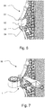
- Fig. 6 shows a vehicle cooling module 50 portion after removal of broken mounting assembly.
- Fig. 7 shows the vehicle cooling module portion with the service member.
- the vehicle cooling module 50 in this case part of a radiator, has a slot 51 and at least one contact side wall 53.
- the vehicle cooling module 50 comprises also a front contact wall 52 which after assembly is facing, and preferably is in contact, with the face wall 19 of the service member 1. If there is a plurality of face walls on the vehicle cooling module 50 as shown in Fig.
- the service member 1 can in fact encapsulate them and a correct positioning of the service member may be ensured after inserting the tongue portion 13 into the slot 51 of the vehicle cooling module 50.
- the inclined top wall 17 and bottom wall 18 can follow the shape of the vehicle cooling module 50 for better alignment and protection of the connection. In Fig. 7 , the top wall 17 is not inclined.
- the contact side wall 53 may comprise a hole or a through-hole 54 for a screw coaxial with the through hole 19 of the service member for fixing together the vehicle cooling module 50 and the service member 1 in a secured manner. In such case, a screw is inserted into both of the openings after assembly, and removed if needed for another replacement of the servicing member if another crash occurs.
- the service member may after assembly and upon crash will break within the connection area 30. The components thereof may then be removed and another servicing member may be mounted.
Landscapes
- Engineering & Computer Science (AREA)
- Chemical & Material Sciences (AREA)
- Combustion & Propulsion (AREA)
- Transportation (AREA)
- Mechanical Engineering (AREA)
- Cooling, Air Intake And Gas Exhaust, And Fuel Tank Arrangements In Propulsion Units (AREA)
Abstract
Description
- The invention concerns a service member for replacing a broken mounting assembly of a vehicle cooling module. The invention further relates to a vehicle cooling module with a service member and a combination thereof.
- Vehicles of all kinds, for example motor vehicles, passenger cars and trucks, have cooling components for a cooling system. Usually, cooling radiators are located at the front of the vehicle, behind the bumper. These are therefore often damaged during a head-on collision, even at low speeds. If the water tank or the core of the cooling element is damaged, the radiator is out of order and the vehicle cannot be driven to the nearest repair shop and must be towed away. In addition, if the water tank or, more generally, the cooling radiator is damaged, the radiator must be replaced with a new radiator, resulting in high repair costs.
- It is already known from the state of the art to mount the radiator or more generally the vehicle cooling module on the vehicle with mounting assemblies. In the event of a frontal collision, these mounting assemblies break off and the radiator itself remains undamaged. After an accident, the mounting assembly must be replaced.
- In known solutions, the vehicle cooling module is fitted with a separate plastic fixing element, e.g. a dovetail on successive cooling modules. In the event of an accident, this separate plastic fixing element is replaced by an identical part. This solution requires an additional part, i.e. the separate plastic fixing element, to be attached not only to one vehicle cooling module as a repair solution after an accident, but to all successive cooling modules. This means additional working time and thus additional costs.
- There is a need for a service member which can be easily attached to a vehicle cooling module after an accident, thus minimizing the costs for the repair. There is also a need for a vehicle cooling module that is mounted in such a way that in the event of a head-on collision the water tank will not leak and that is easy to repair with a service member.
- The object of the invention is, among others, a servicing member for a vehicle cooling module, comprising a first element with a bumper portion, a first fixing interface located on the first element for fixing to the vehicle module, a second element connected to the first element, a second fixing interface located on the second element for fixing the servicing member to a vehicle structure, wherein the first element is connected with the second element by a connection portion adapted to controllably break upon imparting a predetermined force to the bumper portion, wherein the first fixing interface comprises a tongue portion, the tongue portion being adapted for releasable connection with a slot in the vehicle cooling module, the first fixing interface comprising a first side wall extending adjacent to the tongue portion between said tongue portion and the bumper portion so that a free space is created between the tongue portion and the first side wall.
- Preferably, wherein the tongue portion is of plate-like shape and rectangular cross-section.
- Preferably, the tongue portion comprises a blocking section adapted for frictional fixing in a slot of a vehicle cooling module.
- Preferably, the bumper portion is adapted to work along the impact axis, and the tongue portion extends along a tongue axis perpendicular to impact axis.
- Preferably, the first side wall extends along an axis Yw perpendicular to the impact axis Xb and the tongue axis Zt.
- Preferably, the service member further comprises a second side wall extending parallel to the first side wall on the opposite side of the tongue portion.
- Preferably, the service member further comprises a top wall extending over the tongue portion when looked along an axis Yt going through the tongue portion parallel to the Yw axis.
- Preferably, the top wall is inclined with respect to the tongue portion.
- Preferably, the service member further comprises a bottom wall extending below the tongue portion when looked along an axis Yt going through the tongue portion parallel to the Yw axis, the bottom wall being located on the opposite side of the tongue portion with respect to the top wall.
- Preferably, the bottom wall is inclined with respect to the tongue portion.
- Preferably, the service member further comprises a face wall perpendicular to the first side wall, wherein the tongue portion protrudes from the face wall.
- Preferably, the first side wall comprises a through-hole for a screw.
- Another object of the invention is an assembly comprising a service member as described and a vehicle cooling module, the vehicle cooling module comprising a slot and at least one contact side wall, the service member being attached to the vehicle cooling module so that the tongue portion is introduced into the slot and the first side wall is in contact with the contact side wall.
- Another object of the invention is an assembly comprising a service member as described and a vehicle cooling module, wherein the contact side wall comprises a through-hole for a screw coaxial with the through hole of the service member for fixing together the vehicle cooling module and the service member.
- Examples of the invention will be apparent from and described in detail with reference to the accompanying drawings, in which:
-
Figs. 1a-1c show breaking of the mounting assembly and replacement by a service member according to the invention; -
Fig. 2 shows the service member in a perspective view; -
Figs. 3a and 3b show the service member in top view with a closer view on connection portion; -
Fig. 4 shows another perspective view of the service member; -
Fig. 5 shows cross-section view of the service member; -
Fig. 6 shows a vehicle cooling module portion after removal of broken mounting assembly; -
Fig. 7 shows a vehicle cooling module portion with a service member. -
Figs. 1a-1c show breaking of the mounting assembly of avehicle cooling module 50 and replacement by aservice member 1 according to the invention. Once the vehicle hits an object, a force is transferred from car beam bycrash bumper 61 tovehicle cooling module 50.Mounting element 62, serving as attachment means of thevehicle cooling module 50 to vehicle's structure, breaks in a predetermined place. If the radiator is not damaged, thecrash bumper 61 is removed, the broken area is polished off and aservice member 1 is mounted on the cooling module. The details of theservice member 1 will be explained below. -
Fig. 2 shows theservice member 1 in a perspective view. In general, theservice member 1 comprises afirst element 10 with abumper portion 11 and asecond element 20 connected to thefirst element 10. The function of thefirst element 10 is to receive impact from the car beam or other vehicle components. Thefirst element 10 is also used for mounting theservice member 1 to thevehicle cooling module 50. Thesecond element 20 is intended for mounting theservice member 1 to the vehicle structure. What follows is that thesecond element 20 serves as mounting means for thevehicle cooling module 50. -
Figs. 3a and 3b show theservice member 1 in top view with a closer view onconnection portion 30. Thefirst element 10 is connected with thesecond element 20 by aconnection portion 30 adapted to controllably break upon imparting a predetermined force to thebumper portion 11. In particular, theconnection portion 30 comprises a connectingarm 31 between thefirst element 10 and thesecond element 20. Preferably, there is a plurality of connectingarms 31. At least one of thearms 31 has a weakenedportion 32 intended to break more easily than the rest of thearms 31. This may be realized by selectively reducing the thickness of the arm. In this case, there are threearms 31 connecting the first andsecond elements portion 32. Thanks to this weakenedportion 32 it is possible to control the propagation of the crack line to run only through thearms 31, without going in the direction of either thefirst element 10 or thesecond element 20. -
Fig. 4 shows another perspective view of theservice member 1, whileFig. 5 shows a cross-section view. On thefirst element 10 there is located afirst fixing interface 12 for fixing theservice member 1 to thevehicle module 50, while on thesecond element 20 there is located asecond fixing interface 22 for fixing the servicingmember 1 to the vehicle structure. - The
first fixing interface 12 comprises atongue portion 13. Thetongue portion 13 is adapted for releasable connection with aslot 51 in thevehicle cooling module 50. In other words, thetongue portion 13 is shaped and dimensioned so that it can be inserted into adedicated slot 51 in thevehicle cooling module 50 so that it is securely attached thereto, while retaining a possibility of detachment. Preferably, thetongue portion 13 is of plate-like shape and rectangular cross-section. The cross-section of thetongue portion 13 may be decreasing along its length for improved securing within theslot 51. Thetongue portion 13 may comprise ablocking section 14 adapted for frictional fixing in aslot 51 of avehicle cooling module 50. This blockingsection 14 can be for example locally enlarged thickness. - The
first fixing interface 12 comprises afirst side wall 15 extending adjacent to thetongue portion 13 between saidtongue portion 13 and thebumper portion 11 so that a free space is created between thetongue portion 13 and theside wall 15. In general, thebumper portion 11 is adapted to work along the impact axis Xb, and thetongue portion 13 extends along a tongue axis Zt perpendicular to impact axis Xb. Thefirst side wall 15 extends along an axis Yw perpendicular to the impact axis Xb and the tongue axis Zt. Preferably, thefirst side wall 15 is a flat wall which extends from thetongue portion 13 substantially below thetongue portion 13, preferably at a distance at least double the thickness of thetongue portion 13 measured along axis Yt. - As shown in
Fig. 5 , there is a free space between thetongue portion 13 and thefirst side wall 15 when viewed along an axis Xt parallel to the impact axis Xb, the axis Xt going through thetongue portion 13. - The
service member 1 may further comprise asecond side wall 16 extending parallel to thefirst side wall 15 on the opposite side of thetongue portion 13. Additionally, theservice member 1 may further comprise atop wall 17 extending over thetongue portion 13 when looked along an axis Yt going through thetongue portion 13 parallel to the Yw axis. Thetop wall 17 may inclined with respect to thetongue portion 13. There may be also abottom wall 18 extending below thetongue portion 13 when looked along an axis Yt going through thetongue portion 13 parallel to the Yw axis, thebottom wall 18 being located on the opposite side of thetongue portion 13 with respect to thetop wall 17. Thisbottom wall 18 may be inclined with respect to thetongue portion 13. Thetongue portion 13 may protrude from aface wall 19 which is perpendicular to thefirst side wall 13. In any case, there is a space created at least between thetongue portion 13 and thefirst side wall 15 into which a portion of the vehicle cooling module is introduced for secured connection which enables force transfer upon impact received through thebumper portion 11. Because the force may be transferred securely, theconnection portion 30 is allowed to break controllably. This particular design allows to achieve this in a simple and cost effective manner. - The
first side wall 15 may comprise ahole 19 for a screw, for example a through-hole, enabling more secure connection to thevehicle cooling module 50. -
Fig. 6 shows avehicle cooling module 50 portion after removal of broken mounting assembly. In the same perspective,Fig. 7 shows the vehicle cooling module portion with the service member. Thevehicle cooling module 50, in this case part of a radiator, has aslot 51 and at least onecontact side wall 53. When theservice member 1 is attached to thevehicle cooling module 50, thetongue portion 13 is introduced into theslot 51 and thefirst side wall 15 is in contact with thecontact side wall 53. In this manner, a secure arrangement is created between the coolingmodule 50 and theservice member 1. Preferably, thevehicle cooling module 50 comprises also afront contact wall 52 which after assembly is facing, and preferably is in contact, with theface wall 19 of theservice member 1. If there is a plurality of face walls on thevehicle cooling module 50 as shown inFig. 6 , theservice member 1 can in fact encapsulate them and a correct positioning of the service member may be ensured after inserting thetongue portion 13 into theslot 51 of thevehicle cooling module 50. The inclinedtop wall 17 andbottom wall 18 can follow the shape of thevehicle cooling module 50 for better alignment and protection of the connection. InFig. 7 , thetop wall 17 is not inclined. - The
contact side wall 53 may comprise a hole or a through-hole 54 for a screw coaxial with the throughhole 19 of the service member for fixing together thevehicle cooling module 50 and theservice member 1 in a secured manner. In such case, a screw is inserted into both of the openings after assembly, and removed if needed for another replacement of the servicing member if another crash occurs. - In any case, the service member may after assembly and upon crash will break within the
connection area 30. The components thereof may then be removed and another servicing member may be mounted. - Other variations to the disclosed embodiments can be understood and effected by those skilled in the art in practicing the claimed invention, from a study of drawings, the disclosure, and the appended claims. The mere fact that certain measures are recited in mutually different dependent claims does not indicate that a combination of these measures cannot be used to the advantage.
Claims (14)
- A servicing member 1 for a vehicle cooling module 50, comprising a first element 10 with a bumper portion 11, a first fixing interface 12 located on the first element 10 for fixing to the vehicle module 50, a second element 20 connected to the first element 10, a second fixing interface 22 located on the second element 20 for fixing the servicing member 1 to a vehicle structure, wherein the first element 10 is connected with the second element 20 by a connection portion 30 adapted to controllably break upon imparting a predetermined force to the bumper portion 11, wherein the first fixing interface 12 comprises a tongue portion 13, the tongue portion 13 being adapted for releasable connection with a slot 51 in the vehicle cooling module 50, the first fixing interface 12 comprising a first side wall 15 extending adjacent to the tongue portion 13 between said tongue portion 13 and the bumper portion 11 so that a free space is created between the tongue portion 13 and the first side wall 15.
- A servicing member 1 according to preceding claim, wherein the tongue portion 13 is of plate-like shape and rectangular cross-section.
- A servicing member 1 according to claim 2, wherein the tongue portion 13 comprises a blocking section 14 adapted for frictional fixing in a slot 51 of a vehicle cooling module 50.
- A servicing member 1 according to any preceding claim, wherein the bumper portion 11 is adapted to work along the impact axis Xb, and the tongue portion 13 extends along a tongue axis Zt perpendicular to impact axis Xb.
- A servicing member 1 according to claim 4, wherein the first side wall 15 extends along an axis Yw perpendicular to the impact axis Xb and the tongue axis Zt.
- A servicing member 1 according to any preceding claim, further comprising a second side wall 16 extending parallel to the first side wall 15 on the opposite side of the tongue portion 13.
- A servicing member 1 according to any preceding claim, further comprising a top wall 17 extending over the tongue portion 13 when looked along an axis Yt going through the tongue portion 13 parallel to the Yw axis.
- A service member 1 according to claim 7, wherein the top wall 17 is inclined with respect to the tongue portion 13.
- A servicing member 1 according to any preceding claim, further comprising a bottom wall 18 extending below the tongue portion 13 when looked along an axis Yt going through the tongue portion 13 parallel to the Yw axis, the bottom wall 18 being located on the opposite side of the tongue portion 13 with respect to the top wall 17.
- A service member 1 according to claim 9, wherein the bottom wall 18 is inclined with respect to the tongue portion 13.
- A service member 1 according to any preceding claim, further comprising a face wall 19 perpendicular to the first side wall 13, wherein the tongue portion 13 protrudes from the face wall 19.
- A service member 1 according to any preceding claim, wherein the first side wall 15 comprises a through-hole 19 for a screw.
- An assembly comprising a service member 1 according to any preceding claim and a vehicle cooling module 50, the vehicle cooling module comprising a slot 51 and at least one contact side wall 53, the service member 1 being attached to the vehicle cooling module 50 so that the tongue portion 13 is introduced into the slot 51 and the first side wall 15 is in contact with the contact side wall 53.
- An assembly according to claim 12 and 13, wherein the contact side wall 53 comprises a hole 54 for a screw coaxial with the through-hole 19 of the service member for fixing together the vehicle cooling module 50 and the service member 1.
Priority Applications (4)
| Application Number | Priority Date | Filing Date | Title |
|---|---|---|---|
| EP20461530.6A EP3900969A1 (en) | 2020-04-20 | 2020-04-20 | Service member for a vehicle cooling module and a vehicle cooling module with the service member |
| CN202180027241.3A CN115443226B (en) | 2020-04-20 | 2021-04-09 | Repair component for a vehicle cooling module and vehicle cooling module having the same |
| US17/918,342 US12409722B2 (en) | 2020-04-20 | 2021-04-09 | Service member for a vehicle cooling module and a vehicle cooling module with the service member |
| PCT/EP2021/059295 WO2021213816A1 (en) | 2020-04-20 | 2021-04-09 | Service member for a vehicle cooling module and a vehicle cooling module with the service member |
Applications Claiming Priority (1)
| Application Number | Priority Date | Filing Date | Title |
|---|---|---|---|
| EP20461530.6A EP3900969A1 (en) | 2020-04-20 | 2020-04-20 | Service member for a vehicle cooling module and a vehicle cooling module with the service member |
Publications (1)
| Publication Number | Publication Date |
|---|---|
| EP3900969A1 true EP3900969A1 (en) | 2021-10-27 |
Family
ID=70391060
Family Applications (1)
| Application Number | Title | Priority Date | Filing Date |
|---|---|---|---|
| EP20461530.6A Pending EP3900969A1 (en) | 2020-04-20 | 2020-04-20 | Service member for a vehicle cooling module and a vehicle cooling module with the service member |
Country Status (4)
| Country | Link |
|---|---|
| US (1) | US12409722B2 (en) |
| EP (1) | EP3900969A1 (en) |
| CN (1) | CN115443226B (en) |
| WO (1) | WO2021213816A1 (en) |
Citations (3)
| Publication number | Priority date | Publication date | Assignee | Title |
|---|---|---|---|---|
| EP1957346A1 (en) * | 2005-12-05 | 2008-08-20 | Peguform Gmbh | Front end module for a motor vehicle having an energy-absorbing protective function for a cooling module |
| DE102009043794A1 (en) * | 2009-09-30 | 2011-03-31 | Valeo Gmbh | Repair element for replacing broken mounting pin of vehicle cooling module, has lug, which forms positioning pin, another lug, which forms replacement pin and retaining bracket, which is integrally molded at repair element |
| EP2966393A1 (en) * | 2014-07-07 | 2016-01-13 | Valeo Autosystemy SP. Z.O.O. | An integrated bracket for automotive heat exchanger |
Family Cites Families (11)
| Publication number | Priority date | Publication date | Assignee | Title |
|---|---|---|---|---|
| DE2233737C2 (en) * | 1971-07-12 | 1983-02-03 | Société Anonyme Française du Ferodo, 75017 Paris | Heat exchangers, in particular radiators for a motor vehicle |
| GB1599841A (en) * | 1977-01-24 | 1981-10-07 | Beckley A S | Modular impact energy absorbing system for vehicles |
| JPH0326983Y2 (en) * | 1985-03-20 | 1991-06-11 | ||
| US6223811B1 (en) * | 1998-10-05 | 2001-05-01 | Valeo Inc. | Support for a cooling device |
| US7117927B2 (en) * | 2004-09-14 | 2006-10-10 | Delphi Technologies, Inc. | Snap-on mounting bracket for heat exchangers |
| JP4479740B2 (en) * | 2007-03-23 | 2010-06-09 | 日産自動車株式会社 | Car body front structure and car body front pipe fixing bracket |
| JP4658157B2 (en) * | 2008-04-28 | 2011-03-23 | 豊田鉄工株式会社 | Vehicle cooling component support device |
| JP5467525B2 (en) * | 2010-07-28 | 2014-04-09 | スズキ株式会社 | Support structure for vehicle coolant reserve tank |
| CA2830698C (en) * | 2011-04-07 | 2018-09-18 | Dana Canada Corporation | Heat exchanger with resiliently mounted bracket |
| US9146061B2 (en) * | 2013-05-06 | 2015-09-29 | Denso International America, Inc. | Fastener-less retained heat exchanger mounting bracket for low installation force |
| CN206510749U (en) * | 2017-01-10 | 2017-09-22 | 宁波吉利汽车研究开发有限公司 | A kind of protection device for vehicle cooling device |
-
2020
- 2020-04-20 EP EP20461530.6A patent/EP3900969A1/en active Pending
-
2021
- 2021-04-09 CN CN202180027241.3A patent/CN115443226B/en active Active
- 2021-04-09 WO PCT/EP2021/059295 patent/WO2021213816A1/en not_active Ceased
- 2021-04-09 US US17/918,342 patent/US12409722B2/en active Active
Patent Citations (3)
| Publication number | Priority date | Publication date | Assignee | Title |
|---|---|---|---|---|
| EP1957346A1 (en) * | 2005-12-05 | 2008-08-20 | Peguform Gmbh | Front end module for a motor vehicle having an energy-absorbing protective function for a cooling module |
| DE102009043794A1 (en) * | 2009-09-30 | 2011-03-31 | Valeo Gmbh | Repair element for replacing broken mounting pin of vehicle cooling module, has lug, which forms positioning pin, another lug, which forms replacement pin and retaining bracket, which is integrally molded at repair element |
| EP2966393A1 (en) * | 2014-07-07 | 2016-01-13 | Valeo Autosystemy SP. Z.O.O. | An integrated bracket for automotive heat exchanger |
Also Published As
| Publication number | Publication date |
|---|---|
| US20230147303A1 (en) | 2023-05-11 |
| WO2021213816A1 (en) | 2021-10-28 |
| CN115443226A (en) | 2022-12-06 |
| US12409722B2 (en) | 2025-09-09 |
| CN115443226B (en) | 2025-09-23 |
Similar Documents
| Publication | Publication Date | Title |
|---|---|---|
| CN103402802B (en) | For the fender guard of electric apparatus mounted on vehicle | |
| CN102548788B (en) | Vehicle charging port arrangement | |
| CN102905957B (en) | Vehicle collision protection apparatus | |
| JP4943494B2 (en) | Auxiliary guide structure at the time of vehicle collision | |
| EP3461692B1 (en) | Sensor protector and vehicle equipped therewith | |
| EP4026758B1 (en) | Vehicle headlamp mounting assembly and vehicle | |
| US9358864B2 (en) | Device for fastening a battery module to a bodyshell of a motor vehicle | |
| JP2026509629A (en) | Mounting bracket assembly, inclined cooling module assembly and vehicle | |
| US6758515B2 (en) | Front end structure of vehicle with crushable zones for collision damage | |
| US12409722B2 (en) | Service member for a vehicle cooling module and a vehicle cooling module with the service member | |
| JP2011121399A (en) | Mounting structure for head lamp | |
| JP7141998B2 (en) | Protective member and protective structure | |
| CN117337256A (en) | Fixture with planned break for holding sensor | |
| WO2015161182A1 (en) | Adapter for crush rail and torque box | |
| US7331414B2 (en) | Protective structure for an electrical circuit device | |
| CN220374282U (en) | Anti-impact protection structure of automobile water tank | |
| JPH04243628A (en) | Automobile radiator supporting structure | |
| CN220298283U (en) | vehicle | |
| CN114274903A (en) | Exterior structure of automobile and automobile | |
| CN220764514U (en) | Anti-collision structure of A column front end and vehicle | |
| CN208069398U (en) | Cooling module and automobile | |
| CN217730203U (en) | Radiator mounting structure and car | |
| EP4458618A1 (en) | Sensing device fixing unit for an industrial vehicle | |
| JP5609227B2 (en) | Electric junction box for vehicle and electric junction box fixing structure for vehicle | |
| US20260054539A1 (en) | Vehicle having electric air conditioning compressor protection assembly |
Legal Events
| Date | Code | Title | Description |
|---|---|---|---|
| PUAI | Public reference made under article 153(3) epc to a published international application that has entered the european phase |
Free format text: ORIGINAL CODE: 0009012 |
|
| STAA | Information on the status of an ep patent application or granted ep patent |
Free format text: STATUS: THE APPLICATION HAS BEEN PUBLISHED |
|
| AK | Designated contracting states |
Kind code of ref document: A1 Designated state(s): AL AT BE BG CH CY CZ DE DK EE ES FI FR GB GR HR HU IE IS IT LI LT LU LV MC MK MT NL NO PL PT RO RS SE SI SK SM TR |
|
| B565 | Issuance of search results under rule 164(2) epc |
Effective date: 20200925 |
|
| STAA | Information on the status of an ep patent application or granted ep patent |
Free format text: STATUS: REQUEST FOR EXAMINATION WAS MADE |
|
| 17P | Request for examination filed |
Effective date: 20220427 |
|
| RBV | Designated contracting states (corrected) |
Designated state(s): AL AT BE BG CH CY CZ DE DK EE ES FI FR GB GR HR HU IE IS IT LI LT LU LV MC MK MT NL NO PL PT RO RS SE SI SK SM TR |
|
| P01 | Opt-out of the competence of the unified patent court (upc) registered |
Effective date: 20230528 |
|
| STAA | Information on the status of an ep patent application or granted ep patent |
Free format text: STATUS: EXAMINATION IS IN PROGRESS |
|
| 17Q | First examination report despatched |
Effective date: 20230816 |