EP3900848A1 - Dielectric elastomer drive system and dielectric elastomer drive method - Google Patents
Dielectric elastomer drive system and dielectric elastomer drive method Download PDFInfo
- Publication number
- EP3900848A1 EP3900848A1 EP18943616.5A EP18943616A EP3900848A1 EP 3900848 A1 EP3900848 A1 EP 3900848A1 EP 18943616 A EP18943616 A EP 18943616A EP 3900848 A1 EP3900848 A1 EP 3900848A1
- Authority
- EP
- European Patent Office
- Prior art keywords
- dielectric elastomer
- unit
- elastomer drive
- drive unit
- charge
- Prior art date
- Legal status (The legal status is an assumption and is not a legal conclusion. Google has not performed a legal analysis and makes no representation as to the accuracy of the status listed.)
- Withdrawn
Links
Images



Classifications
-
- B—PERFORMING OPERATIONS; TRANSPORTING
- B06—GENERATING OR TRANSMITTING MECHANICAL VIBRATIONS IN GENERAL
- B06B—METHODS OR APPARATUS FOR GENERATING OR TRANSMITTING MECHANICAL VIBRATIONS OF INFRASONIC, SONIC, OR ULTRASONIC FREQUENCY, e.g. FOR PERFORMING MECHANICAL WORK IN GENERAL
- B06B1/00—Methods or apparatus for generating mechanical vibrations of infrasonic, sonic, or ultrasonic frequency
- B06B1/02—Methods or apparatus for generating mechanical vibrations of infrasonic, sonic, or ultrasonic frequency making use of electrical energy
- B06B1/0292—Electrostatic transducers, e.g. electret-type
-
- H—ELECTRICITY
- H02—GENERATION; CONVERSION OR DISTRIBUTION OF ELECTRIC POWER
- H02N—ELECTRIC MACHINES NOT OTHERWISE PROVIDED FOR
- H02N1/00—Electrostatic generators or motors using a solid moving electrostatic charge carrier
- H02N1/002—Electrostatic motors
- H02N1/006—Electrostatic motors of the gap-closing type
-
- H—ELECTRICITY
- H10—SEMICONDUCTOR DEVICES; ELECTRIC SOLID-STATE DEVICES NOT OTHERWISE PROVIDED FOR
- H10N—ELECTRIC SOLID-STATE DEVICES NOT OTHERWISE PROVIDED FOR
- H10N30/00—Piezoelectric or electrostrictive devices
- H10N30/80—Constructional details
- H10N30/802—Circuitry or processes for operating piezoelectric or electrostrictive devices not otherwise provided for, e.g. drive circuits
-
- H—ELECTRICITY
- H10—SEMICONDUCTOR DEVICES; ELECTRIC SOLID-STATE DEVICES NOT OTHERWISE PROVIDED FOR
- H10N—ELECTRIC SOLID-STATE DEVICES NOT OTHERWISE PROVIDED FOR
- H10N30/00—Piezoelectric or electrostrictive devices
- H10N30/80—Constructional details
- H10N30/85—Piezoelectric or electrostrictive active materials
- H10N30/857—Macromolecular compositions
-
- B—PERFORMING OPERATIONS; TRANSPORTING
- B06—GENERATING OR TRANSMITTING MECHANICAL VIBRATIONS IN GENERAL
- B06B—METHODS OR APPARATUS FOR GENERATING OR TRANSMITTING MECHANICAL VIBRATIONS OF INFRASONIC, SONIC, OR ULTRASONIC FREQUENCY, e.g. FOR PERFORMING MECHANICAL WORK IN GENERAL
- B06B2201/00—Indexing scheme associated with B06B1/0207 for details covered by B06B1/0207 but not provided for in any of its subgroups
- B06B2201/50—Application to a particular transducer type
- B06B2201/51—Electrostatic transducer
Definitions
- the present invention relates to a dielectric elastomer drive system and a dielectric elastomer drive method.
- a dielectric elastomer drive system using a dielectric elastomer drive unit that includes a dielectric elastomer layer and a pair of flexible electrode layers flanking the dielectric elastomer layer see Patent Document 1, for example.
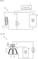
- Fig. 11 shows an example of a conventional dielectric elastomer drive system.
- the dielectric elastomer drive unit 91 is placed in a contracted state.
- An elongated state resulting from the application of voltage and a contracted state resulting from stopping the application of voltage can be freely selected by employing a method such as pre-elongating the dielectric elastomer drive unit 91. This makes it possible to drive the dielectric elastomer drive unit 91.
- the dielectric elastomer drive unit 91 is elongated very quickly in response to the application of voltage, and is therefore attracting attention as a drive unit having excellent responsiveness.
- the pair of electrode layers 912 flanking the dielectric elastomer layer 911 electrically constitute a capacitor.
- a charge is stored in the pair of electrode layers 912. The charge remains in the capacitor and does not disappear spontaneously.
- the charge stored in the pair of electrode layers 912 hinders improvement of the contraction speed of the dielectric elastomer drive unit 91 as compared to the elongation speed of the dielectric elastomer drive unit 91.
- Patent Document 1 JP-A-2009-124875
- the present invention has been conceived in view of the circumstances noted above, and aims to provide a dielectric elastomer drive system and a dielectric elastomer drive method that are capable of improving responsiveness.
- a dielectric elastomer drive system that comprises: a dielectric elastomer drive unit including a dielectric elastomer layer and a pair of electrode layers flanking the dielectric elastomer layer; a power supply unit that applies voltage to the dielectric elastomer drive unit; and a charge removal unit that removes a charge stored in the dielectric elastomer drive unit.
- the dielectric elastomer drive system further includes a main switch unit that opens or closes the connection between the dielectric elastomer drive unit and the charge removal unit.
- the dielectric elastomer drive system further includes a power-supply-side switch unit that opens or closes the connection between the dielectric elastomer drive unit and the power supply unit.
- the charge removal unit converts the charge stored in the dielectric elastomer drive unit to thermal energy.
- the main switch unit opens or closes the connection between the charge removal unit and a wiring path connecting the power supply unit and the dielectric elastomer drive unit.
- the main switch unit switches between a first state in which the dielectric elastomer drive unit is connected to the power supply unit and a second state in which the dielectric elastomer drive unit is connected to the charge removal unit.
- the charge removal unit temporarily stores the charge in the dielectric elastomer drive unit.
- the dielectric elastomer drive system further includes a power storage unit that stores a charge temporarily stored in the charge removal unit.
- the dielectric elastomer drive system further includes a sub-switch unit that opens or closes the connection between the charge removal unit and the power storage unit.
- the state of the main switch unit is changed by elongation and contraction of the dielectric elastomer drive unit.
- the main switch unit connects the dielectric elastomer drive unit and the charge removal unit to each other when the dielectric elastomer drive unit is elongated by application of voltage.
- the main switch unit connects the dielectric elastomer drive unit and the power supply unit to each other when the dielectric elastomer drive unit is contracted by no application of voltage.
- a method for driving a dielectric elastomer comprises: applying voltage to a dielectric elastomer drive unit including a dielectric elastomer layer and a pair of electrode layers flanking the dielectric elastomer layer; stopping application of voltage to the dielectric elastomer drive unit; and removing, with use of a charge removal unit, the charge stored in the dielectric elastomer drive unit.
- Fig. 1 shows a dielectric elastomer drive system according to a first embodiment of the present invention.
- a dielectric elastomer drive system A1 according to the present embodiment includes a dielectric elastomer drive unit 1, a charge removal unit 2, a main switch unit 31, a switch unit 33, a power supply unit 5, and a control unit 6.
- the dielectric elastomer drive unit 1 outputs a driving force in the dielectric elastomer drive system A1.
- the dielectric elastomer drive unit 1 has a dielectric elastomer layer 11 and a pair of electrode layers 12.
- the dielectric elastomer layer 11 is required to be elastically deformable and to have high insulating strength.
- Some preferable examples of the material of the dielectric elastomer layer 11 include, but not limited to, silicone elastomers and acrylic elastomers.
- the electrode layers 12 are made of a conductive material that is elastically deformable following the elastic deformation of the dielectric elastomer layer 11. Such a material may be obtained by mixing an elastically deformable main material with a filler that provides conductivity.
- the filler may preferably be a carbon nanotube, for example.
- the dielectric elastomer drive unit 1 When the dielectric elastomer drive unit 1 is not subjected to any external force or restraint, and is in a state where no voltage is applied by the power supply unit 5, the dielectric elastomer drive unit 1 is in a natural length state where no voluntary elongation or contraction has occurred. When the dielectric elastomer drive unit 1 is subjected to an external force, the dielectric elastomer layer 11 can elastically deform. When voltage is applied by the power supply unit 5, positive and negative charges are stored in the pair of electrode layers 12 with the dielectric elastomer layer 11 therebetween. The Coulomb force of these charges cause the pair of electrode layers 12 to be attracted to each other, allowing the dielectric elastomer layer 11 to be compressed in the thickness direction.
- the dielectric elastomer drive unit 1 can behave in a manner that the dimension in the planar direction is elongated by application of voltage.
- the dielectric elastomer layer 11 of the dielectric elastomer drive unit 1 may be pre-elongated so that the dielectric elastomer layer 11 is alternately and freely placed in an elongated state and in a contracted state opposite to the elongated state resulting from the application of voltage.
- the dielectric elastomer drive unit 1 may be provided with a supporting mechanism (not shown) for maintaining the pre-elongated state.
- the dielectric elastomer drive unit 1 may be provided with an elastic member (not shown) for elongating the dielectric elastomer layer 11 when necessary.
- the charge removal unit 2 removes the charge stored in the pair of electrode layers 12 of the dielectric elastomer drive unit 1, and is connected in parallel to the pair of electrode layers 12 in the illustrated example.
- the charge removal unit 2 is not limited to any specific configuration as long as it has a function of removing charges.
- the charge removal unit 2 is configured with a resistor.
- the power supply unit 5 applies voltage to the pair of electrode layers 12 in order to drive the dielectric elastomer drive unit 1.
- the power supply unit 5 is not limited to any specific configuration, as long as it can apply a predetermined voltage to the pair of electrode layers 12 at a predetermined time by an instruction from the control unit 6.
- the main switch unit 31 is provided in the conductive path between the pair of electrode layers 12 (the dielectric elastomer drive unit 1) and the charge removal unit 2, and opens or closes to establish or cut off the connection between the pair of electrode layers 12 (the dielectric elastomer drive unit 1) and the charge removal unit 2.
- the main switch unit 31 is not particularly limited to any specific configuration.
- the main switch unit 31 may be a switch mechanism that mechanically operates or a semiconductor element such as a transistor as appropriate.
- the main switch unit 31 is opened or closed by an instruction from the control unit 6.
- the main switch unit 31 is configured to open or close to establish or cut off the connection between the charge removal unit 2 and a wiring path connecting the power supply unit 5 and the dielectric elastomer drive unit 1.
- the switch unit 33 is provided in the conductive path between the pair of electrode layers 12 (the dielectric elastomer drive unit 1) and the power supply unit 5, and opens or closes to establish or cut off the connection between the pair of electrode layers 12 (the dielectric elastomer drive unit 1) and the power supply unit 5.
- the switch unit 33 corresponds to a power-supply-side switch unit.
- the switch unit 33 also functions to open or close to establish or cut off the connection between the charge removal unit 2 and the power supply unit 5.
- the switch unit 33 is not particularly limited to any specific configuration.
- the switch unit 33 may be a switch mechanism that mechanically operates, or may be a semiconductor element such as a transistor as appropriate.
- the switch unit 33 is opened or closed by an instruction from the control unit 6.
- the control unit 6 controls the application of voltage by the power supply unit 5 and the opening/closing operations of the main switch unit 31 and the switch unit 33, so that the dielectric elastomer drive system A1 is driven in a desirable manner.
- the control unit 6 is not limited to any specific configuration, and may include a CPU and a memory.
- the charge removal unit 2, the power supply unit 5, the control unit 6, the main switch unit 31, and the switch unit 33 are not limited to being configured as independent units. For example, some of these units may be integrated into a single device as long as it can execute the respective functions of the units integrated therein.
- the power supply unit 5 and the control unit 6 may be configured as an integrated power supply device.
- the power supply unit 5 and the charge removal unit 2 may be configured as an integrated device.
- the main switch unit 31 and the switch unit 33 are opened by an instruction from the control unit 6. Accordingly, the dielectric elastomer drive unit 1, the charge removal unit 2, and the power supply unit 5 are not connected to each other, and no voltage is applied to the dielectric elastomer drive unit 1. In this state, the Coulomb force that attracts the pair of electrode layers 12 to each other is not generated, and the dielectric elastomer drive unit 1 is in a contracted state.
- Fig. 2 shows the dielectric elastomer drive system A1 when the dielectric elastomer drive unit 1 is placed in an elongated state by an instruction from the control unit 6.
- the switch unit 33 is closed by an instruction from the control unit 6, whereby the pair of electrode layers 12 (the dielectric elastomer drive unit 1) and the power supply unit 5 are connected to each other.
- the main switch unit 31 is kept open, so that the pair of electrode layers 12 (the dielectric elastomer drive unit 1) and the charge removal unit 2 are not connected to each other.
- the power supply unit 5 applies voltage to the pair of electrode layers 12 by an instruction from the control unit 6.
- a charge q1 is stored in the pair of electrode layers 12 to generate the Coulomb force.
- the dielectric elastomer layer 11 is contracted in the thickness direction and elongated in the planar direction, and the dielectric elastomer drive unit 1 is thus placed in an elongated state.
- Fig. 3 shows the dielectric elastomer drive system A1 when the dielectric elastomer drive unit 1 in an elongated state as shown in Fig. 2 is placed in a contracted state again by an instruction from the control unit 6.
- the application of voltage by the power supply unit 5 is stopped by an instruction from the control unit 6.
- the switch unit 33 is opened and the main switch unit 31 is closed by an instruction from the control unit 6.
- the dielectric elastomer drive unit 1 and the power supply unit 5 are disconnected from each other, and the dielectric elastomer drive unit 1 and the charge removal unit 2 are connected to each other. This causes the charge q1 stored in the pair of electrode layers 12 to form an electric current and flow to the charge removal unit 2.
- the charge removal unit 2 is configured with a resistor in the present embodiment, the charge q1 forming a current is converted to thermal energy h1 by the charge removal unit 2. As a result, the charge q1 stored in the pair of electrode layers 12 of the dielectric elastomer drive unit 1 is removed by the charge removal unit 2. This causes the dielectric elastomer drive unit 1 to promptly return to the state where no voltage is applied and to be placed in a contracted state again.
- the dielectric elastomer drive unit 1 in the dielectric elastomer drive system A1 outputs a drive force by appropriately repeating an elongated state and a contracted state as shown in Figs. 2 and 3 by instructions from the control unit 6.
- the charge q1 is stored in the pair of electrode layers 12. Since the dielectric elastomer drive unit 1 is a capacitor, the charge q1 stored in the pair of electrode layers 12 does not disappear spontaneously. When the charge q1 remains, the Coulomb force is generated that causes the pair of electrode layers 12 to be attracted to each other. As a result, the dielectric elastomer drive unit 1 may continue to be in the elongated state. Accordingly, even when the power supply unit 5 stops applying voltage to place the dielectric elastomer drive unit 1 to be in a contracted state from an elongated state, a prompt transition to the contracted state is hindered by the remaining charge q1.
- the dielectric elastomer drive unit 1 is connected to the charge removal unit 2.
- the charge removal unit 2 functions to remove the charge q1 stored in the dielectric elastomer drive unit 1. Accordingly, as shown in Fig. 3 , when the power supply unit 5 stops applying voltage and the charge removal unit 2 removes the charge q1 of the dielectric elastomer drive unit 1, the dielectric elastomer drive unit 1 can promptly transition from an elongated state to a contracted state. This improves the responsiveness of the dielectric elastomer drive system A1.
- the dielectric elastomer drive system A1 includes the main switch unit 31.
- the main switch unit 31 In the transition to an elongated state as shown in Fig. 2 , the main switch unit 31 is opened, whereby the voltage for the dielectric elastomer drive unit 1 is prevented from being applied to the charge removal unit 2.
- the main switch unit 31 In the transition to a contracted state as shown in Fig. 3 , the main switch unit 31 is closed, whereby the dielectric elastomer drive unit 1 and the charge removal unit 2 are connected to each other and the charge removal unit 2 removes the charge q1 stored in the dielectric elastomer drive unit 1. This is preferable for improving the responsiveness of the dielectric elastomer drive system A1 and suppressing an undesired loss.
- the charge removal unit 2 is configured with a resistor.
- the charge removal unit 2 configured with a resistor converts a passing current (charge q1) to the thermal energy h1 without delay.
- Such a configuration is suitable for the charge removal unit 2 to promptly remove the charge q1 of the dielectric elastomer drive unit 1.
- Figs. 4 to 10 show other embodiments of the present invention.
- elements that are the same as or similar to those in the above embodiment are provided with the same reference signs as in the above embodiment.
- Fig. 4 shows a dielectric elastomer drive system according to a second embodiment of the present invention.
- a dielectric elastomer drive system A2 according to the present embodiment is different from the above-described dielectric elastomer drive system A1 in the configuration of the charge removal unit 2, and further includes a sub-switch unit 32 and a power storage unit 4.
- the charge removal unit 2 is configured with a capacitor, and functions to temporarily store the charge removed from the dielectric elastomer drive unit 1.
- the capacitor that constitutes the charge removal unit 2 is not limited to any specific configuration. From the viewpoint of effectively removing the charge stored in the pair of electrode layers 12 of the dielectric elastomer drive unit 1, the capacitance of the capacitor that constitutes the charge removal unit 2 is preferably sufficiently larger than the capacitance of the dielectric elastomer drive unit 1.
- the power storage unit 4 stores, as electric energy, the charge temporarily stored in the charge removal unit 2, and is configured with a secondary battery such as a lithium-ion battery.
- the power storage unit 4 is selectively connected to the charge removal unit 2.
- the charge removal unit 2 may function as a step-down circuit that lowers the voltage for charging the power storage unit 4.
- the capacitance of the capacitor that constitutes the charge removal unit 2 may be selected such that the voltage applied to the power storage unit 4 has a desired value.
- the sub-switch unit 32 is provided in the conductive path between the charge removal unit 2 and the power storage unit 4, and opens or closes to establish or cut off the connection between the charge removal unit 2 and the power storage unit 4.
- the sub-switch unit 32 is not particularly limited to any specific configuration.
- the sub-switch unit 32 may be a switch mechanism that mechanically operates, or may be a semiconductor element such as a transistor as appropriate.
- the sub-switch unit 32 is opened or closed by an instruction from the control unit 6.
- the main switch unit 31, the sub-switch unit 32, and the switch unit 33 are opened by an instruction from the control unit 6. Accordingly, the dielectric elastomer drive unit 1, the charge removal unit 2, the power storage unit 4, and the power supply unit 5 are not connected to each other, and no voltage is applied to the dielectric elastomer drive unit 1. In this state, the Coulomb force that attracts the pair of electrode layers 12 to each other is not generated, and the dielectric elastomer drive unit 1 is in a contracted state.
- Fig. 5 shows the dielectric elastomer drive system A2 when the dielectric elastomer drive unit 1 is placed in an elongated state by an instruction from the control unit 6.
- the switch unit 33 is closed by an instruction from the control unit 6, whereby the pair of electrode layers 12 (the dielectric elastomer drive unit 1) and the power supply unit 5 are connected to each other.
- the main switch unit 31 and the sub-switch unit 32 are kept open.
- the power supply unit 5 applies voltage to the pair of electrode layers 12 by an instruction from the control unit 6.
- a charge q1 is stored in the pair of electrode layers 12 to generate the Coulomb force.
- the dielectric elastomer layer 11 is contracted in the thickness direction and elongated in the planar direction, and the dielectric elastomer drive unit 1 is thus placed in an elongated state.
- Fig. 6 shows the dielectric elastomer drive system A2 when the dielectric elastomer drive unit 1 in an elongated state as shown in Fig. 5 is placed in a contracted state again by an instruction from the control unit 6.
- the application of voltage by the power supply unit 5 is stopped by an instruction from the control unit 6.
- the switch unit 33 is opened and the main switch unit 31 is closed by an instruction from the control unit 6.
- the dielectric elastomer drive unit 1 and the power supply unit 5 are disconnected from each other, and the dielectric elastomer drive unit 1 and the charge removal unit 2 are connected to each other. This causes the charge q1 stored in the pair of electrode layers 12 to form an electric current and flow to the charge removal unit 2.
- the sub-switch unit 32 is kept open, so that the charge removal unit 2 and the power storage unit 4 are not connected to each other.
- the charge removal unit 2 is configured with a capacitor, so that the charge q1 forming a current is stored in the charge removal unit 2 as charge q2.
- the quantity of the charge q1 is substantially the same as the quantity of the charge q2.
- the charge q1 stored in the pair of electrode layers 12 of the dielectric elastomer drive unit 1 is removed by the charge removal unit 2. This causes the dielectric elastomer drive unit 1 to promptly return to the state where no voltage is applied and to be placed in a contracted state again.
- Fig. 7 shows the dielectric elastomer drive system A2 when the charge q2 in the charge removal unit 2 is stored in the power storage unit 4 by an instruction from the control unit 6.
- the main switch unit 31 is opened and the sub-switch unit 32 is closed by an instruction from the control unit 6. This causes the charge q2 stored in the charge removal unit 2 to form a current and flow to the power storage unit 4. As a result, electric energy corresponding to charge q3 is stored in the power storage unit 4.
- the quantity of charge q3 is less than the quantity of charge q2 by the quantity corresponding to, for example, the loss in the conductive path from the charge removal unit 2 to the power storage unit 4, the internal loss in the power storage unit 4, and the loss resulting from the power storage reaction in the power storage unit 4.
- Fig. 8 shows another example of storing electric energy from the charge removal unit 2 to the power storage unit 4.
- the sub-switch unit 32 and the switch unit 33 are closed, and the main switch unit 31 is opened by an instruction from the control unit 6.
- voltage is applied from the power supply unit 5 to the dielectric elastomer drive unit 1 by an instruction from the control unit 6. In this way, the process of storing electric energy from the charge removal unit 2 to the power storage unit 4 is performed in parallel with the operation of elongating the dielectric elastomer drive unit 1.
- the process of storing electric energy from the charge removal unit 2 to the power storage unit 4 can be performed either when the dielectric elastomer drive unit 1 is stopped and therefore the voltage application state thereof does not change or when the dielectric elastomer drive unit 1 is in operation and therefore the voltage application state thereof changes.
- the charge removal unit 2 configured with a resistor
- the charge removal unit 2 configured with a capacitor is suitable for promptly removing the charge q1 of the dielectric elastomer drive unit 1.
- the charge removal unit 2 functions to store the charge q1 as the charge q2, instead of converting the charge q1 to the thermal energy h1 and releasing the thermal energy h1. In this way, the charge q1 that is inputted to elongate the dielectric elastomer drive unit 1 can be reused as the charge q2, which contributes power saving.
- the charge removal unit 2 and the power storage unit 4 are connected to each other via the sub-switch unit 32.
- the sub-switch unit 32 When the sub-switch unit 32 is closed in a state where the charge q2 is stored in the charge removal unit 2, the charge q2 of the charge removal unit 2 can be stored in the power storage unit 4.
- the power storage unit 4 configured with a secondary battery has a much larger storage capacity than the charge removal unit 2.
- the storage speed of the power storage unit 4 is much slower than that of the charge removal unit 2 configured with the capacitor.
- the charge removal unit 2 it is preferable for the charge removal unit 2 to remove the charge q1 from the dielectric elastomer drive unit 1 from the viewpoint of both improving the responsiveness and saving power, since this approach allows for maintaining the transition speed of the dielectric elastomer drive unit 1 to the contracted state at high speed and storing all the collected charge q2 in the power storage unit 4.
- Fig. 9 shows a dielectric elastomer drive system according to a third embodiment of the present invention.
- a dielectric elastomer drive system A3 according to the present embodiment is different from the dielectric elastomer drive system A1 in the configuration of the main switch unit 31 and in not having the switch unit 33, but is similar to the dielectric elastomer drive system A1 in the other configurations.
- the main switch unit 31 is configured to switch between the state in which the dielectric elastomer drive unit 1 is connected to the power supply unit 5 and the state in which the dielectric elastomer drive unit 1 is connected to the charge removal unit 2. In other words, in the illustrated state, the main switch unit 31 connects the dielectric elastomer drive unit 1 and the power supply unit 5 to each other, and disconnects the dielectric elastomer drive unit 1 and the charge removal unit 2 from each other.
- the main switch unit 31 connects the dielectric elastomer drive unit 1 and the charge removal unit 2 to each other, and disconnects the dielectric elastomer drive unit 1 and the power supply unit 5 from each other.
- the main switch unit 31 switches between the state in which the dielectric elastomer drive unit 1 is connected to the power supply unit 5 and the state in which the dielectric elastomer drive unit 1 is connected to the charge removal unit 2.
- the main switch unit 31 may be further configured to switch to the state in which the dielectric elastomer drive unit 1 is disconnected from both of the power supply unit 5 and the charge removal unit 2.
- Such an embodiment as described above can also improve the responsiveness of the dielectric elastomer drive system A3. Furthermore, the embodiment advantageously eliminates the need for the switch unit 33 in the dielectric elastomer drive system A1.
- Fig. 10 shows a dielectric elastomer drive system according to a fourth embodiment of the present invention.
- the dielectric elastomer drive unit 1 is attached to a pair of supporting members 71.
- the pair of supporting members 71 are circular plate-like members, for example, and have different sizes.
- the dielectric elastomer drive unit 1 is attached to the pair of supporting members 71, thereby having a tubular truncated-cone shape.
- the pair of supporting members 71 sandwich a spring 72.
- the spring 72 exerts an elastic force that elongates the dielectric elastomer drive unit 1 in the axial direction. Because of this, when no voltage is applied by the power supply unit 5, a tension is generated that elongates the dielectric elastomer drive unit 1 in the axial direction.
- the upper supporting member 71 has a connecting rod 73 attached thereto.
- the connecting rod 73 moves up and down together with the upper supporting member 71 as the dielectric elastomer drive unit 1 is elongated and contracted, and transmits the movement resulting from the elongation and contraction of the dielectric elastomer drive unit 1 to the main switch unit 31.
- the main switch unit 31 has a mover 310, and stators 311 and 312.
- One end of the connecting rod 73 is fixed to the mover 310. Accordingly, the mover 310 moves up and down as the connecting rod 73 moves up and down.
- the mover 310 is electrically connected to the inner electrode layer 12 of the dielectric elastomer drive unit 1.
- the stators 311 and 312 are separated apart from each other with the mover 310 therebetween.
- the stator 311 is connected to the power supply unit 5, and the stator 312 is connected to the charge removal unit 2.
- the mover 310 is in contact with the stator 311, and the dielectric elastomer drive unit 1 is connected to the power supply unit 5.
- the dielectric elastomer drive unit 1 is elongated in the axial direction by the application of voltage from the power supply unit 5, the upper supporting member 71, the connecting rod 73, and the mover 310 move up. This causes the mover 310 to be separated from the stator 311 to make contact with the stator 312. As a result, the dielectric elastomer drive unit 1 is disconnected (electrically cut off) from the power supply unit 5 and connected to the charge removal unit 2.
- the charge of the dielectric elastomer drive unit 1 is removed by the charge removal unit 2 to contract the dielectric elastomer drive unit 1.
- the upper supporting member 71, the connecting rod 73, and the mover 310 move down. This causes the mover 310 to be separated from the stator 312 to make contact with the stator 311 again. After that, the upper supporting member 71, the connecting rod 73, and the mover 310 repeatedly move up and down.
- Such an embodiment as described above can also improve the responsiveness of a dielectric elastomer drive system A4.
- the dielectric elastomer drive system A4 is configured to change the state of the main switch unit 31 by the elongation and contraction of the dielectric elastomer drive unit 1.
- the dielectric elastomer drive system A4 can cause the dielectric elastomer drive unit 1 to perform a vibrating operation by repeating elongation and contraction, without using e.g., the control unit 6 according to the above embodiments or an oscillator.
- the dielectric elastomer drive system according to the present invention is not limited to the above embodiments. Various design changes can be made to the specific configurations of the elements of the dielectric elastomer drive system according to the present invention.
Landscapes
- Engineering & Computer Science (AREA)
- Mechanical Engineering (AREA)
- Physics & Mathematics (AREA)
- Spectroscopy & Molecular Physics (AREA)
- General Electrical Machinery Utilizing Piezoelectricity, Electrostriction Or Magnetostriction (AREA)
- Micromachines (AREA)
Abstract
Description
- The present invention relates to a dielectric elastomer drive system and a dielectric elastomer drive method.
- There has been proposed a dielectric elastomer drive system using a dielectric elastomer drive unit that includes a dielectric elastomer layer and a pair of flexible electrode layers flanking the dielectric elastomer layer (see
Patent Document 1, for example).Fig. 11 shows an example of a conventional dielectric elastomer drive system. When voltage is applied to a pair ofelectrode layers 912 from apower supply unit 92 in a dielectric elastomer drive system X, the pair ofelectrode layers 912 are attracted to each other by Coulomb force. This reduces the thickness of adielectric elastomer layer 911 having significant flexibility, and increases the dimension in a planar direction. As a result, the dielectricelastomer drive unit 91 is placed in a contracted state. An elongated state resulting from the application of voltage and a contracted state resulting from stopping the application of voltage can be freely selected by employing a method such as pre-elongating the dielectricelastomer drive unit 91. This makes it possible to drive the dielectricelastomer drive unit 91. - The dielectric
elastomer drive unit 91 is elongated very quickly in response to the application of voltage, and is therefore attracting attention as a drive unit having excellent responsiveness. However, the pair ofelectrode layers 912 flanking thedielectric elastomer layer 911 electrically constitute a capacitor. When voltage is applied to the pair ofelectrode layers 912 to elongate the dielectricelastomer drive unit 91, a charge is stored in the pair ofelectrode layers 912. The charge remains in the capacitor and does not disappear spontaneously. The charge stored in the pair ofelectrode layers 912 hinders improvement of the contraction speed of the dielectricelastomer drive unit 91 as compared to the elongation speed of the dielectricelastomer drive unit 91. - Patent Document 1:
JP-A-2009-124875 - The present invention has been conceived in view of the circumstances noted above, and aims to provide a dielectric elastomer drive system and a dielectric elastomer drive method that are capable of improving responsiveness.
- According to the present invention, there is provided a dielectric elastomer drive system that comprises: a dielectric elastomer drive unit including a dielectric elastomer layer and a pair of electrode layers flanking the dielectric elastomer layer; a power supply unit that applies voltage to the dielectric elastomer drive unit; and a charge removal unit that removes a charge stored in the dielectric elastomer drive unit.
- In a preferred embodiment of the present invention, the dielectric elastomer drive system further includes a main switch unit that opens or closes the connection between the dielectric elastomer drive unit and the charge removal unit.
- In a preferred embodiment of the present invention, the dielectric elastomer drive system further includes a power-supply-side switch unit that opens or closes the connection between the dielectric elastomer drive unit and the power supply unit.
- In a preferred embodiment of the present invention, the charge removal unit converts the charge stored in the dielectric elastomer drive unit to thermal energy.
- In a preferred embodiment of the present invention, the main switch unit opens or closes the connection between the charge removal unit and a wiring path connecting the power supply unit and the dielectric elastomer drive unit.
- In a preferred embodiment of the present invention, the main switch unit switches between a first state in which the dielectric elastomer drive unit is connected to the power supply unit and a second state in which the dielectric elastomer drive unit is connected to the charge removal unit.
- In a preferred embodiment of the present invention, the charge removal unit temporarily stores the charge in the dielectric elastomer drive unit.
- In a preferred embodiment of the present invention, the dielectric elastomer drive system further includes a power storage unit that stores a charge temporarily stored in the charge removal unit.
- In a preferred embodiment of the present invention, the dielectric elastomer drive system further includes a sub-switch unit that opens or closes the connection between the charge removal unit and the power storage unit.
- In a preferred embodiment of the present invention, the state of the main switch unit is changed by elongation and contraction of the dielectric elastomer drive unit. The main switch unit connects the dielectric elastomer drive unit and the charge removal unit to each other when the dielectric elastomer drive unit is elongated by application of voltage. The main switch unit connects the dielectric elastomer drive unit and the power supply unit to each other when the dielectric elastomer drive unit is contracted by no application of voltage.
- A method for driving a dielectric elastomer, provided by a second aspect of the present invention, comprises: applying voltage to a dielectric elastomer drive unit including a dielectric elastomer layer and a pair of electrode layers flanking the dielectric elastomer layer; stopping application of voltage to the dielectric elastomer drive unit; and removing, with use of a charge removal unit, the charge stored in the dielectric elastomer drive unit.
- According to the present invention, it is possible to improve the responsiveness of the dielectric elastomer drive system.
- Other features and advantages of the present invention will be more apparent from detailed description given below with reference to the accompanying drawings.
-
-
Fig. 1 is a system configuration diagram showing a dielectric elastomer drive system according to a first embodiment of the present invention. -
Fig. 2 is a system configuration diagram showing an operational example of the dielectric elastomer drive system according to the first embodiment of the present invention. -
Fig. 3 is a system configuration diagram showing an operational example of the dielectric elastomer drive system according to the first embodiment of the present invention. -
Fig. 4 is a system configuration diagram showing a dielectric elastomer drive system according to a second embodiment of the present invention. -
Fig. 5 is a system configuration diagram showing an operational example of the dielectric elastomer drive system according to the second embodiment of the present invention. -
Fig. 6 is a system configuration diagram showing an operational example of the dielectric elastomer drive system according to the second embodiment of the present invention. -
Fig. 7 is a system configuration diagram showing an operational example of the dielectric elastomer drive system according to the second embodiment of the present invention. -
Fig. 8 is a system configuration diagram showing an operational example of the dielectric elastomer drive system according to the second embodiment of the present invention. -
Fig. 9 is a system configuration diagram showing a dielectric elastomer drive system according to a third embodiment of the present invention. -
Fig. 10 is a system configuration diagram showing the dielectric elastomer drive system according to the third embodiment of the present invention. -
Fig. 11 is a system configuration diagram showing an example of a conventional dielectric elastomer drive system. - Preferred embodiments of the present invention are described in detail below with reference to the accompanying drawings.
-
Fig. 1 shows a dielectric elastomer drive system according to a first embodiment of the present invention. A dielectric elastomer drive system A1 according to the present embodiment includes a dielectricelastomer drive unit 1, acharge removal unit 2, amain switch unit 31, aswitch unit 33, apower supply unit 5, and acontrol unit 6. - The dielectric
elastomer drive unit 1 outputs a driving force in the dielectric elastomer drive system A1. The dielectricelastomer drive unit 1 has adielectric elastomer layer 11 and a pair ofelectrode layers 12. - The
dielectric elastomer layer 11 is required to be elastically deformable and to have high insulating strength. Some preferable examples of the material of thedielectric elastomer layer 11 include, but not limited to, silicone elastomers and acrylic elastomers. - The pair of
electrode layers 12, to which voltage is applied by thepower supply unit 5, flank thedielectric elastomer layer 11. Theelectrode layers 12 are made of a conductive material that is elastically deformable following the elastic deformation of thedielectric elastomer layer 11. Such a material may be obtained by mixing an elastically deformable main material with a filler that provides conductivity. The filler may preferably be a carbon nanotube, for example. - When the dielectric
elastomer drive unit 1 is not subjected to any external force or restraint, and is in a state where no voltage is applied by thepower supply unit 5, the dielectricelastomer drive unit 1 is in a natural length state where no voluntary elongation or contraction has occurred. When the dielectricelastomer drive unit 1 is subjected to an external force, thedielectric elastomer layer 11 can elastically deform. When voltage is applied by thepower supply unit 5, positive and negative charges are stored in the pair ofelectrode layers 12 with thedielectric elastomer layer 11 therebetween. The Coulomb force of these charges cause the pair ofelectrode layers 12 to be attracted to each other, allowing thedielectric elastomer layer 11 to be compressed in the thickness direction. Due to the compression in the thickness direction, the dimension of thedielectric elastomer layer 11 in the planar direction is elongated. In this way, the dielectricelastomer drive unit 1 can behave in a manner that the dimension in the planar direction is elongated by application of voltage. - The
dielectric elastomer layer 11 of the dielectricelastomer drive unit 1 may be pre-elongated so that thedielectric elastomer layer 11 is alternately and freely placed in an elongated state and in a contracted state opposite to the elongated state resulting from the application of voltage. When necessary, the dielectricelastomer drive unit 1 may be provided with a supporting mechanism (not shown) for maintaining the pre-elongated state. Alternatively, the dielectricelastomer drive unit 1 may be provided with an elastic member (not shown) for elongating thedielectric elastomer layer 11 when necessary. - The
charge removal unit 2 removes the charge stored in the pair of electrode layers 12 of the dielectricelastomer drive unit 1, and is connected in parallel to the pair of electrode layers 12 in the illustrated example. Thecharge removal unit 2 is not limited to any specific configuration as long as it has a function of removing charges. In the present embodiment, thecharge removal unit 2 is configured with a resistor. - The
power supply unit 5 applies voltage to the pair of electrode layers 12 in order to drive the dielectricelastomer drive unit 1. Thepower supply unit 5 is not limited to any specific configuration, as long as it can apply a predetermined voltage to the pair of electrode layers 12 at a predetermined time by an instruction from thecontrol unit 6. - The
main switch unit 31 is provided in the conductive path between the pair of electrode layers 12 (the dielectric elastomer drive unit 1) and thecharge removal unit 2, and opens or closes to establish or cut off the connection between the pair of electrode layers 12 (the dielectric elastomer drive unit 1) and thecharge removal unit 2. Themain switch unit 31 is not particularly limited to any specific configuration. For example, themain switch unit 31 may be a switch mechanism that mechanically operates or a semiconductor element such as a transistor as appropriate. In the present embodiment, themain switch unit 31 is opened or closed by an instruction from thecontrol unit 6. In the present embodiment, themain switch unit 31 is configured to open or close to establish or cut off the connection between thecharge removal unit 2 and a wiring path connecting thepower supply unit 5 and the dielectricelastomer drive unit 1. - The
switch unit 33 is provided in the conductive path between the pair of electrode layers 12 (the dielectric elastomer drive unit 1) and thepower supply unit 5, and opens or closes to establish or cut off the connection between the pair of electrode layers 12 (the dielectric elastomer drive unit 1) and thepower supply unit 5. Theswitch unit 33 corresponds to a power-supply-side switch unit. In the present embodiment, theswitch unit 33 also functions to open or close to establish or cut off the connection between thecharge removal unit 2 and thepower supply unit 5. Theswitch unit 33 is not particularly limited to any specific configuration. For example, theswitch unit 33 may be a switch mechanism that mechanically operates, or may be a semiconductor element such as a transistor as appropriate. In the present embodiment, theswitch unit 33 is opened or closed by an instruction from thecontrol unit 6. - The
control unit 6 controls the application of voltage by thepower supply unit 5 and the opening/closing operations of themain switch unit 31 and theswitch unit 33, so that the dielectric elastomer drive system A1 is driven in a desirable manner. Thecontrol unit 6 is not limited to any specific configuration, and may include a CPU and a memory. - The
charge removal unit 2, thepower supply unit 5, thecontrol unit 6, themain switch unit 31, and theswitch unit 33 are not limited to being configured as independent units. For example, some of these units may be integrated into a single device as long as it can execute the respective functions of the units integrated therein. For example, thepower supply unit 5 and thecontrol unit 6 may be configured as an integrated power supply device. Alternatively, thepower supply unit 5 and thecharge removal unit 2 may be configured as an integrated device. - The following describes an operational example of the dielectric elastomer drive system A1 with reference to
Figs. 1 to 3 . - In the state shown in
Fig. 1 , themain switch unit 31 and theswitch unit 33 are opened by an instruction from thecontrol unit 6. Accordingly, the dielectricelastomer drive unit 1, thecharge removal unit 2, and thepower supply unit 5 are not connected to each other, and no voltage is applied to the dielectricelastomer drive unit 1. In this state, the Coulomb force that attracts the pair of electrode layers 12 to each other is not generated, and the dielectricelastomer drive unit 1 is in a contracted state. -
Fig. 2 shows the dielectric elastomer drive system A1 when the dielectricelastomer drive unit 1 is placed in an elongated state by an instruction from thecontrol unit 6. Theswitch unit 33 is closed by an instruction from thecontrol unit 6, whereby the pair of electrode layers 12 (the dielectric elastomer drive unit 1) and thepower supply unit 5 are connected to each other. On the other hand, themain switch unit 31 is kept open, so that the pair of electrode layers 12 (the dielectric elastomer drive unit 1) and thecharge removal unit 2 are not connected to each other. In this state, thepower supply unit 5 applies voltage to the pair of electrode layers 12 by an instruction from thecontrol unit 6. As such, a charge q1 is stored in the pair of electrode layers 12 to generate the Coulomb force. As a result, thedielectric elastomer layer 11 is contracted in the thickness direction and elongated in the planar direction, and the dielectricelastomer drive unit 1 is thus placed in an elongated state. -
Fig. 3 shows the dielectric elastomer drive system A1 when the dielectricelastomer drive unit 1 in an elongated state as shown inFig. 2 is placed in a contracted state again by an instruction from thecontrol unit 6. The application of voltage by thepower supply unit 5 is stopped by an instruction from thecontrol unit 6. Furthermore, theswitch unit 33 is opened and themain switch unit 31 is closed by an instruction from thecontrol unit 6. As a result, the dielectricelastomer drive unit 1 and thepower supply unit 5 are disconnected from each other, and the dielectricelastomer drive unit 1 and thecharge removal unit 2 are connected to each other. This causes the charge q1 stored in the pair of electrode layers 12 to form an electric current and flow to thecharge removal unit 2. Since thecharge removal unit 2 is configured with a resistor in the present embodiment, the charge q1 forming a current is converted to thermal energy h1 by thecharge removal unit 2. As a result, the charge q1 stored in the pair of electrode layers 12 of the dielectricelastomer drive unit 1 is removed by thecharge removal unit 2. This causes the dielectricelastomer drive unit 1 to promptly return to the state where no voltage is applied and to be placed in a contracted state again. - In this way, the dielectric
elastomer drive unit 1 in the dielectric elastomer drive system A1 outputs a drive force by appropriately repeating an elongated state and a contracted state as shown inFigs. 2 and3 by instructions from thecontrol unit 6. - The following describes the advantages of the dielectric elastomer drive system A1.
- When voltage is applied to the dielectric
elastomer drive unit 1 to place the dielectricelastomer drive unit 1 in an elongated state as shown inFig. 2 , the charge q1 is stored in the pair of electrode layers 12. Since the dielectricelastomer drive unit 1 is a capacitor, the charge q1 stored in the pair of electrode layers 12 does not disappear spontaneously. When the charge q1 remains, the Coulomb force is generated that causes the pair of electrode layers 12 to be attracted to each other. As a result, the dielectricelastomer drive unit 1 may continue to be in the elongated state. Accordingly, even when thepower supply unit 5 stops applying voltage to place the dielectricelastomer drive unit 1 to be in a contracted state from an elongated state, a prompt transition to the contracted state is hindered by the remaining charge q1. - In the present embodiment, the dielectric
elastomer drive unit 1 is connected to thecharge removal unit 2. Thecharge removal unit 2 functions to remove the charge q1 stored in the dielectricelastomer drive unit 1. Accordingly, as shown inFig. 3 , when thepower supply unit 5 stops applying voltage and thecharge removal unit 2 removes the charge q1 of the dielectricelastomer drive unit 1, the dielectricelastomer drive unit 1 can promptly transition from an elongated state to a contracted state. This improves the responsiveness of the dielectric elastomer drive system A1. - The dielectric elastomer drive system A1 includes the
main switch unit 31. In the transition to an elongated state as shown inFig. 2 , themain switch unit 31 is opened, whereby the voltage for the dielectricelastomer drive unit 1 is prevented from being applied to thecharge removal unit 2. In the transition to a contracted state as shown inFig. 3 , themain switch unit 31 is closed, whereby the dielectricelastomer drive unit 1 and thecharge removal unit 2 are connected to each other and thecharge removal unit 2 removes the charge q1 stored in the dielectricelastomer drive unit 1. This is preferable for improving the responsiveness of the dielectric elastomer drive system A1 and suppressing an undesired loss. - In the present embodiment, the
charge removal unit 2 is configured with a resistor. Thecharge removal unit 2 configured with a resistor converts a passing current (charge q1) to the thermal energy h1 without delay. Such a configuration is suitable for thecharge removal unit 2 to promptly remove the charge q1 of the dielectricelastomer drive unit 1. -
Figs. 4 to 10 show other embodiments of the present invention. In these figures, elements that are the same as or similar to those in the above embodiment are provided with the same reference signs as in the above embodiment. -
Fig. 4 shows a dielectric elastomer drive system according to a second embodiment of the present invention. A dielectric elastomer drive system A2 according to the present embodiment is different from the above-described dielectric elastomer drive system A1 in the configuration of thecharge removal unit 2, and further includes asub-switch unit 32 and apower storage unit 4. - In the present embodiment, the
charge removal unit 2 is configured with a capacitor, and functions to temporarily store the charge removed from the dielectricelastomer drive unit 1. The capacitor that constitutes thecharge removal unit 2 is not limited to any specific configuration. From the viewpoint of effectively removing the charge stored in the pair of electrode layers 12 of the dielectricelastomer drive unit 1, the capacitance of the capacitor that constitutes thecharge removal unit 2 is preferably sufficiently larger than the capacitance of the dielectricelastomer drive unit 1. - The
power storage unit 4 stores, as electric energy, the charge temporarily stored in thecharge removal unit 2, and is configured with a secondary battery such as a lithium-ion battery. Thepower storage unit 4 is selectively connected to thecharge removal unit 2. In the present embodiment, thecharge removal unit 2 may function as a step-down circuit that lowers the voltage for charging thepower storage unit 4. In this case, the capacitance of the capacitor that constitutes thecharge removal unit 2 may be selected such that the voltage applied to thepower storage unit 4 has a desired value. - The
sub-switch unit 32 is provided in the conductive path between thecharge removal unit 2 and thepower storage unit 4, and opens or closes to establish or cut off the connection between thecharge removal unit 2 and thepower storage unit 4. Thesub-switch unit 32 is not particularly limited to any specific configuration. For example, thesub-switch unit 32 may be a switch mechanism that mechanically operates, or may be a semiconductor element such as a transistor as appropriate. In the present embodiment, thesub-switch unit 32 is opened or closed by an instruction from thecontrol unit 6. - The following describes an operational example of the dielectric elastomer drive system A2 with reference to
Figs. 4 to 8 . - In the state shown in
Fig. 4 , themain switch unit 31, thesub-switch unit 32, and theswitch unit 33 are opened by an instruction from thecontrol unit 6. Accordingly, the dielectricelastomer drive unit 1, thecharge removal unit 2, thepower storage unit 4, and thepower supply unit 5 are not connected to each other, and no voltage is applied to the dielectricelastomer drive unit 1. In this state, the Coulomb force that attracts the pair of electrode layers 12 to each other is not generated, and the dielectricelastomer drive unit 1 is in a contracted state. -
Fig. 5 shows the dielectric elastomer drive system A2 when the dielectricelastomer drive unit 1 is placed in an elongated state by an instruction from thecontrol unit 6. Theswitch unit 33 is closed by an instruction from thecontrol unit 6, whereby the pair of electrode layers 12 (the dielectric elastomer drive unit 1) and thepower supply unit 5 are connected to each other. On the other hand, themain switch unit 31 and thesub-switch unit 32 are kept open. In this state, thepower supply unit 5 applies voltage to the pair of electrode layers 12 by an instruction from thecontrol unit 6. As such, a charge q1 is stored in the pair of electrode layers 12 to generate the Coulomb force. As a result, thedielectric elastomer layer 11 is contracted in the thickness direction and elongated in the planar direction, and the dielectricelastomer drive unit 1 is thus placed in an elongated state. -
Fig. 6 shows the dielectric elastomer drive system A2 when the dielectricelastomer drive unit 1 in an elongated state as shown inFig. 5 is placed in a contracted state again by an instruction from thecontrol unit 6. The application of voltage by thepower supply unit 5 is stopped by an instruction from thecontrol unit 6. Furthermore, theswitch unit 33 is opened and themain switch unit 31 is closed by an instruction from thecontrol unit 6. As a result, the dielectricelastomer drive unit 1 and thepower supply unit 5 are disconnected from each other, and the dielectricelastomer drive unit 1 and thecharge removal unit 2 are connected to each other. This causes the charge q1 stored in the pair of electrode layers 12 to form an electric current and flow to thecharge removal unit 2. Thesub-switch unit 32 is kept open, so that thecharge removal unit 2 and thepower storage unit 4 are not connected to each other. In the present embodiment, thecharge removal unit 2 is configured with a capacitor, so that the charge q1 forming a current is stored in thecharge removal unit 2 as charge q2. When the loss in the conductive path from the dielectricelastomer drive unit 1 to thecharge removal unit 2 is negligible, the quantity of the charge q1 is substantially the same as the quantity of the charge q2. As a result, the charge q1 stored in the pair of electrode layers 12 of the dielectricelastomer drive unit 1 is removed by thecharge removal unit 2. This causes the dielectricelastomer drive unit 1 to promptly return to the state where no voltage is applied and to be placed in a contracted state again. -
Fig. 7 shows the dielectric elastomer drive system A2 when the charge q2 in thecharge removal unit 2 is stored in thepower storage unit 4 by an instruction from thecontrol unit 6. Themain switch unit 31 is opened and thesub-switch unit 32 is closed by an instruction from thecontrol unit 6. This causes the charge q2 stored in thecharge removal unit 2 to form a current and flow to thepower storage unit 4. As a result, electric energy corresponding to charge q3 is stored in thepower storage unit 4. Note that the quantity of charge q3 is less than the quantity of charge q2 by the quantity corresponding to, for example, the loss in the conductive path from thecharge removal unit 2 to thepower storage unit 4, the internal loss in thepower storage unit 4, and the loss resulting from the power storage reaction in thepower storage unit 4. After that, the elongated state shown inFig. 5 and the contracted state shown inFigs. 6 and7 are appropriately repeated again, in response to a request for outputting a drive force required for the dielectric elastomer drive system A2. -
Fig. 8 shows another example of storing electric energy from thecharge removal unit 2 to thepower storage unit 4. In the present example, thesub-switch unit 32 and theswitch unit 33 are closed, and themain switch unit 31 is opened by an instruction from thecontrol unit 6. Furthermore, voltage is applied from thepower supply unit 5 to the dielectricelastomer drive unit 1 by an instruction from thecontrol unit 6. In this way, the process of storing electric energy from thecharge removal unit 2 to thepower storage unit 4 is performed in parallel with the operation of elongating the dielectricelastomer drive unit 1. In other words, the process of storing electric energy from thecharge removal unit 2 to thepower storage unit 4 can be performed either when the dielectricelastomer drive unit 1 is stopped and therefore the voltage application state thereof does not change or when the dielectricelastomer drive unit 1 is in operation and therefore the voltage application state thereof changes. - Such an embodiment as described above can also improve the responsiveness of the dielectric elastomer drive system A2. As with the
charge removal unit 2 configured with a resistor, thecharge removal unit 2 configured with a capacitor is suitable for promptly removing the charge q1 of the dielectricelastomer drive unit 1. Furthermore, thecharge removal unit 2 functions to store the charge q1 as the charge q2, instead of converting the charge q1 to the thermal energy h1 and releasing the thermal energy h1. In this way, the charge q1 that is inputted to elongate the dielectricelastomer drive unit 1 can be reused as the charge q2, which contributes power saving. - As shown in
Fig. 7 , in the present embodiment, thecharge removal unit 2 and thepower storage unit 4 are connected to each other via thesub-switch unit 32. When thesub-switch unit 32 is closed in a state where the charge q2 is stored in thecharge removal unit 2, the charge q2 of thecharge removal unit 2 can be stored in thepower storage unit 4. In general, thepower storage unit 4 configured with a secondary battery has a much larger storage capacity than thecharge removal unit 2. On the other hand, the storage speed of thepower storage unit 4 is much slower than that of thecharge removal unit 2 configured with the capacitor. As such, it is preferable for thecharge removal unit 2 to remove the charge q1 from the dielectricelastomer drive unit 1 from the viewpoint of both improving the responsiveness and saving power, since this approach allows for maintaining the transition speed of the dielectricelastomer drive unit 1 to the contracted state at high speed and storing all the collected charge q2 in thepower storage unit 4. -
Fig. 9 shows a dielectric elastomer drive system according to a third embodiment of the present invention. A dielectric elastomer drive system A3 according to the present embodiment is different from the dielectric elastomer drive system A1 in the configuration of themain switch unit 31 and in not having theswitch unit 33, but is similar to the dielectric elastomer drive system A1 in the other configurations. - In the present embodiment, the
main switch unit 31 is configured to switch between the state in which the dielectricelastomer drive unit 1 is connected to thepower supply unit 5 and the state in which the dielectricelastomer drive unit 1 is connected to thecharge removal unit 2. In other words, in the illustrated state, themain switch unit 31 connects the dielectricelastomer drive unit 1 and thepower supply unit 5 to each other, and disconnects the dielectricelastomer drive unit 1 and thecharge removal unit 2 from each other. On the other hand, when the state of themain switch unit 31 is switched from the illustrated state by an instruction from thecontrol unit 6, themain switch unit 31 connects the dielectricelastomer drive unit 1 and thecharge removal unit 2 to each other, and disconnects the dielectricelastomer drive unit 1 and thepower supply unit 5 from each other. In the above example, themain switch unit 31 switches between the state in which the dielectricelastomer drive unit 1 is connected to thepower supply unit 5 and the state in which the dielectricelastomer drive unit 1 is connected to thecharge removal unit 2. However, in addition to the switching between these two states, themain switch unit 31 may be further configured to switch to the state in which the dielectricelastomer drive unit 1 is disconnected from both of thepower supply unit 5 and thecharge removal unit 2. - Such an embodiment as described above can also improve the responsiveness of the dielectric elastomer drive system A3. Furthermore, the embodiment advantageously eliminates the need for the
switch unit 33 in the dielectric elastomer drive system A1. -
Fig. 10 shows a dielectric elastomer drive system according to a fourth embodiment of the present invention. - In the present embodiment, the dielectric
elastomer drive unit 1 is attached to a pair of supportingmembers 71. The pair of supportingmembers 71 are circular plate-like members, for example, and have different sizes. The dielectricelastomer drive unit 1 is attached to the pair of supportingmembers 71, thereby having a tubular truncated-cone shape. The pair of supportingmembers 71 sandwich aspring 72. Thespring 72 exerts an elastic force that elongates the dielectricelastomer drive unit 1 in the axial direction. Because of this, when no voltage is applied by thepower supply unit 5, a tension is generated that elongates the dielectricelastomer drive unit 1 in the axial direction. - The upper supporting
member 71 has a connectingrod 73 attached thereto. The connectingrod 73 moves up and down together with the upper supportingmember 71 as the dielectricelastomer drive unit 1 is elongated and contracted, and transmits the movement resulting from the elongation and contraction of the dielectricelastomer drive unit 1 to themain switch unit 31. - The
main switch unit 31 has amover 310, andstators rod 73 is fixed to themover 310. Accordingly, themover 310 moves up and down as the connectingrod 73 moves up and down. Themover 310 is electrically connected to theinner electrode layer 12 of the dielectricelastomer drive unit 1. Thestators mover 310 therebetween. Thestator 311 is connected to thepower supply unit 5, and thestator 312 is connected to thecharge removal unit 2. - In the illustrated state, the
mover 310 is in contact with thestator 311, and the dielectricelastomer drive unit 1 is connected to thepower supply unit 5. When the dielectricelastomer drive unit 1 is elongated in the axial direction by the application of voltage from thepower supply unit 5, the upper supportingmember 71, the connectingrod 73, and themover 310 move up. This causes themover 310 to be separated from thestator 311 to make contact with thestator 312. As a result, the dielectricelastomer drive unit 1 is disconnected (electrically cut off) from thepower supply unit 5 and connected to thecharge removal unit 2. In this way, the charge of the dielectricelastomer drive unit 1 is removed by thecharge removal unit 2 to contract the dielectricelastomer drive unit 1. As a result, the upper supportingmember 71, the connectingrod 73, and themover 310 move down. This causes themover 310 to be separated from thestator 312 to make contact with thestator 311 again. After that, the upper supportingmember 71, the connectingrod 73, and themover 310 repeatedly move up and down. - Such an embodiment as described above can also improve the responsiveness of a dielectric elastomer drive system A4. The dielectric elastomer drive system A4 is configured to change the state of the
main switch unit 31 by the elongation and contraction of the dielectricelastomer drive unit 1. As such, the dielectric elastomer drive system A4 can cause the dielectricelastomer drive unit 1 to perform a vibrating operation by repeating elongation and contraction, without using e.g., thecontrol unit 6 according to the above embodiments or an oscillator. - The dielectric elastomer drive system according to the present invention is not limited to the above embodiments. Various design changes can be made to the specific configurations of the elements of the dielectric elastomer drive system according to the present invention.
Claims (11)
- A dielectric elastomer drive system comprising:a dielectric elastomer drive unit including a dielectric elastomer layer and a pair of electrode layers flanking the dielectric elastomer layer;a power supply unit that applies voltage to the dielectric elastomer drive unit; anda charge removal unit that removes a charge stored in the dielectric elastomer drive unit.
- The dielectric elastomer drive system according to claim 1, further comprising a main switch unit that opens or closes a connection between the dielectric elastomer drive unit and the charge removal unit.
- The dielectric elastomer drive system according to claim 2, further comprising a power-supply-side switch unit that opens or closes a connection between the dielectric elastomer drive unit and the power supply unit.
- The dielectric elastomer drive system according to claim 2, wherein the main switch unit opens or closes a connection between the charge removal unit and a wiring path connecting the power supply unit and the dielectric elastomer drive unit.
- The dielectric elastomer drive system according to claim 2, wherein the main switch unit switches between a state in which the dielectric elastomer drive unit is connected to the power supply unit and a state in which the dielectric elastomer drive unit is connected to the charge removal unit.
- The dielectric elastomer drive system according to any of claims 1 to 5, wherein the charge removal unit converts a charge stored in the dielectric elastomer drive unit to thermal energy.
- The dielectric elastomer drive system according to any of claims 1 to 5, wherein the charge removal unit temporarily stores a charge stored in the dielectric elastomer drive unit.
- The dielectric elastomer drive system according to claim 7, further comprising a power storage unit that stores a charge temporarily stored in the charge removal unit.
- The dielectric elastomer drive system according to claim 8, further comprising a sub-switch unit that opens or closes a connection between the charge removal unit and the power storage unit.
- The dielectric elastomer drive system according to claim 5,wherein a state of the main switch unit is changed by elongation and contraction of the dielectric elastomer drive unit,the main switch unit connects the dielectric elastomer drive unit and the charge removal unit to each other when the dielectric elastomer drive unit is elongated by application of voltage, andthe main switch unit connects the dielectric elastomer drive unit and the power supply unit to each other when the dielectric elastomer drive unit is contracted by no application of voltage.
- A method for driving a dielectric elastomer, comprising:applying voltage to a dielectric elastomer drive unit including a dielectric elastomer layer and a pair of electrode layers flanking the dielectric elastomer layer;stopping application of voltage to the dielectric elastomer drive unit; andremoving, with use of a charge removal unit, a charge stored in the dielectric elastomer drive unit.
Applications Claiming Priority (1)
| Application Number | Priority Date | Filing Date | Title |
|---|---|---|---|
| PCT/JP2018/047266 WO2020129239A1 (en) | 2018-12-21 | 2018-12-21 | Dielectric elastomer drive system and dielectric elastomer drive method |
Publications (3)
| Publication Number | Publication Date |
|---|---|
| EP3900848A1 true EP3900848A1 (en) | 2021-10-27 |
| EP3900848A8 EP3900848A8 (en) | 2022-01-12 |
| EP3900848A4 EP3900848A4 (en) | 2022-07-06 |
Family
ID=71100720
Family Applications (1)
| Application Number | Title | Priority Date | Filing Date |
|---|---|---|---|
| EP18943616.5A Withdrawn EP3900848A4 (en) | 2018-12-21 | 2018-12-21 | DIELECTRIC ELASTOMER DRIVE SYSTEM AND DIELECTRIC ELASTOMER DRIVE METHOD |
Country Status (4)
| Country | Link |
|---|---|
| US (1) | US11923790B2 (en) |
| EP (1) | EP3900848A4 (en) |
| CN (1) | CN113195115A (en) |
| WO (1) | WO2020129239A1 (en) |
Family Cites Families (14)
| Publication number | Priority date | Publication date | Assignee | Title |
|---|---|---|---|---|
| US6882086B2 (en) * | 2001-05-22 | 2005-04-19 | Sri International | Variable stiffness electroactive polymer systems |
| AU2001238675A1 (en) | 2000-02-23 | 2001-09-03 | Sri International | Electroactive polymer thermal electric generators |
| JP2005260236A (en) * | 2004-03-10 | 2005-09-22 | Samsung Electro Mech Co Ltd | Polymer dielectric actuator and inchworm robot using the same |
| US7557456B2 (en) * | 2006-05-05 | 2009-07-07 | Sri International | Wave powered generation using electroactive polymers |
| US7977923B2 (en) | 2007-03-09 | 2011-07-12 | Sri International | Circuits for electroactive polymer generators |
| CN101680548A (en) * | 2007-06-19 | 2010-03-24 | 株式会社开滋 | Shaft seal device and valve structure using the same |
| JP5247123B2 (en) | 2007-11-15 | 2013-07-24 | 豊田合成株式会社 | Actuator |
| JP2009159664A (en) * | 2007-12-25 | 2009-07-16 | Hyper Drive Corp | Generating set using electric field responsive high polymer |
| AU2012225355A1 (en) * | 2011-03-09 | 2013-10-10 | Bayer Intellectual Property Gmbh | Electroactive polymer energy converter |
| US9270206B2 (en) * | 2012-01-23 | 2016-02-23 | Alfred E. Mann Foundation For Scientific Research | Methods and systems for applying charge to a piezoelectric element |
| DK2847856T3 (en) * | 2012-05-10 | 2018-08-06 | Single Buoy Moorings | Charging / Discharging Circuits for Electromechanical Energy Conversion and Electromechanical Energy Conversion System |
| WO2014202687A1 (en) * | 2013-06-21 | 2014-12-24 | Abb Ag | Electroactive polymer transducer and switching device with an electroactive polymer transducer |
| JP6998116B2 (en) * | 2017-03-09 | 2022-01-18 | 正毅 千葉 | Dielectric elastomer power generation system |
| JP6978861B2 (en) | 2017-06-23 | 2021-12-08 | 正毅 千葉 | Dielectric elastomer drive system |
-
2018
- 2018-12-21 WO PCT/JP2018/047266 patent/WO2020129239A1/en not_active Ceased
- 2018-12-21 US US17/415,729 patent/US11923790B2/en active Active
- 2018-12-21 EP EP18943616.5A patent/EP3900848A4/en not_active Withdrawn
- 2018-12-21 CN CN201880100362.4A patent/CN113195115A/en active Pending
Also Published As
| Publication number | Publication date |
|---|---|
| EP3900848A8 (en) | 2022-01-12 |
| CN113195115A (en) | 2021-07-30 |
| US20220085735A1 (en) | 2022-03-17 |
| EP3900848A4 (en) | 2022-07-06 |
| WO2020129239A1 (en) | 2020-06-25 |
| US11923790B2 (en) | 2024-03-05 |
Similar Documents
| Publication | Publication Date | Title |
|---|---|---|
| Shian et al. | Optimizing the electrical energy conversion cycle of dielectric elastomer generators | |
| US7977923B2 (en) | Circuits for electroactive polymer generators | |
| US8710793B2 (en) | Electrical converter with variable capacitor | |
| US9585771B2 (en) | Electrically driven artificial hand | |
| CN105849925B (en) | Piezoelectric generator module and remote control | |
| CN100530916C (en) | Step-up type DC-DC converter and method for controlling the same | |
| US20100090669A1 (en) | Buck dc-to-dc converter and method | |
| WO2014202687A1 (en) | Electroactive polymer transducer and switching device with an electroactive polymer transducer | |
| JP2012152009A (en) | Power generator, secondary battery, and electronic apparatus | |
| JP6978861B2 (en) | Dielectric elastomer drive system | |
| US11923790B2 (en) | Dielectric elastomer drive system and dielectric elastomer drive method | |
| JP2008141840A (en) | Generating set using electric field responsive high polymer | |
| CN110729087B (en) | A voltage control material resistance change curve controllable combination device and realization method | |
| JP2015039258A (en) | Drive circuit and driving method | |
| JP6998116B2 (en) | Dielectric elastomer power generation system | |
| CN110816706B (en) | Continuous jumping robot based on active material driving | |
| EP2530806A2 (en) | High-efficiency charging device using a switching arrangement and charging and discharging | |
| US2980841A (en) | Electrostrictive vibrator | |
| JP2016103331A (en) | Switch and power conversion device | |
| JP2011188720A (en) | Driving device | |
| Lo et al. | Understanding efficiency limits of dielectric elastomer driver circuitry | |
| US20020136418A1 (en) | High efficiency regenerative piezoelectric drive amplifier | |
| CN102255556B (en) | Drive circuit and the method controlling capacity cell | |
| WO2011044901A1 (en) | A system and a method for generating electrical energy | |
| WO2020175257A1 (en) | Dielectric elastomer power generation system |
Legal Events
| Date | Code | Title | Description |
|---|---|---|---|
| STAA | Information on the status of an ep patent application or granted ep patent |
Free format text: STATUS: THE INTERNATIONAL PUBLICATION HAS BEEN MADE |
|
| PUAI | Public reference made under article 153(3) epc to a published international application that has entered the european phase |
Free format text: ORIGINAL CODE: 0009012 |
|
| STAA | Information on the status of an ep patent application or granted ep patent |
Free format text: STATUS: REQUEST FOR EXAMINATION WAS MADE |
|
| 17P | Request for examination filed |
Effective date: 20210621 |
|
| AK | Designated contracting states |
Kind code of ref document: A1 Designated state(s): AL AT BE BG CH CY CZ DE DK EE ES FI FR GB GR HR HU IE IS IT LI LT LU LV MC MK MT NL NO PL PT RO RS SE SI SK SM TR |
|
| RAP3 | Party data changed (applicant data changed or rights of an application transferred) |
Owner name: WAKI, MIKIO Owner name: CHIBA, SEIKI Owner name: ZEON CORPORATION |
|
| DAV | Request for validation of the european patent (deleted) | ||
| DAX | Request for extension of the european patent (deleted) | ||
| A4 | Supplementary search report drawn up and despatched |
Effective date: 20220608 |
|
| RIC1 | Information provided on ipc code assigned before grant |
Ipc: H01L 41/04 20060101ALI20220601BHEP Ipc: B06B 1/02 20060101ALI20220601BHEP Ipc: B06B 1/08 20060101AFI20220601BHEP |
|
| RIN1 | Information on inventor provided before grant (corrected) |
Inventor name: SAWADA, MAKOTO Inventor name: ITO, MITSUAKI Inventor name: WAKI, MIKIO Inventor name: CHIBA, SEIKI |
|
| RAP3 | Party data changed (applicant data changed or rights of an application transferred) |
Owner name: ZEON CORPORATION Owner name: WAKI, MIKIO Owner name: CHIBA, SEIKI |
|
| STAA | Information on the status of an ep patent application or granted ep patent |
Free format text: STATUS: EXAMINATION IS IN PROGRESS |
|
| 17Q | First examination report despatched |
Effective date: 20230718 |
|
| REG | Reference to a national code |
Ref country code: DE Ref legal event code: R079 Free format text: PREVIOUS MAIN CLASS: B06B0001080000 Ipc: H10N0030800000 |
|
| GRAP | Despatch of communication of intention to grant a patent |
Free format text: ORIGINAL CODE: EPIDOSNIGR1 |
|
| STAA | Information on the status of an ep patent application or granted ep patent |
Free format text: STATUS: GRANT OF PATENT IS INTENDED |
|
| RIC1 | Information provided on ipc code assigned before grant |
Ipc: H10N 30/80 20230101AFI20250623BHEP Ipc: H10N 30/857 20230101ALI20250623BHEP Ipc: B06B 1/02 20060101ALI20250623BHEP |
|
| INTG | Intention to grant announced |
Effective date: 20250709 |
|
| STAA | Information on the status of an ep patent application or granted ep patent |
Free format text: STATUS: THE APPLICATION IS DEEMED TO BE WITHDRAWN |
|
| 18D | Application deemed to be withdrawn |
Effective date: 20251111 |