EP3900844B1 - Electrode slurry coating method and apparatus comprising pressure adjustment member - Google Patents
Electrode slurry coating method and apparatus comprising pressure adjustment member Download PDFInfo
- Publication number
- EP3900844B1 EP3900844B1 EP20887906.4A EP20887906A EP3900844B1 EP 3900844 B1 EP3900844 B1 EP 3900844B1 EP 20887906 A EP20887906 A EP 20887906A EP 3900844 B1 EP3900844 B1 EP 3900844B1
- Authority
- EP
- European Patent Office
- Prior art keywords
- electrode slurry
- flow path
- discharge flow
- storage tank
- pressure
- Prior art date
- Legal status (The legal status is an assumption and is not a legal conclusion. Google has not performed a legal analysis and makes no representation as to the accuracy of the status listed.)
- Active
Links
Images



Classifications
-
- B—PERFORMING OPERATIONS; TRANSPORTING
- B05—SPRAYING OR ATOMISING IN GENERAL; APPLYING FLUENT MATERIALS TO SURFACES, IN GENERAL
- B05C—APPARATUS FOR APPLYING FLUENT MATERIALS TO SURFACES, IN GENERAL
- B05C11/00—Component parts, details or accessories not specifically provided for in groups B05C1/00 - B05C9/00
- B05C11/10—Storage, supply or control of liquid or other fluent material; Recovery of excess liquid or other fluent material
- B05C11/1002—Means for controlling supply, i.e. flow or pressure, of liquid or other fluent material to the applying apparatus, e.g. valves
-
- B—PERFORMING OPERATIONS; TRANSPORTING
- B05—SPRAYING OR ATOMISING IN GENERAL; APPLYING FLUENT MATERIALS TO SURFACES, IN GENERAL
- B05C—APPARATUS FOR APPLYING FLUENT MATERIALS TO SURFACES, IN GENERAL
- B05C11/00—Component parts, details or accessories not specifically provided for in groups B05C1/00 - B05C9/00
- B05C11/10—Storage, supply or control of liquid or other fluent material; Recovery of excess liquid or other fluent material
- B05C11/1002—Means for controlling supply, i.e. flow or pressure, of liquid or other fluent material to the applying apparatus, e.g. valves
- B05C11/1007—Means for controlling supply, i.e. flow or pressure, of liquid or other fluent material to the applying apparatus, e.g. valves responsive to condition of liquid or other fluent material
- B05C11/1013—Means for controlling supply, i.e. flow or pressure, of liquid or other fluent material to the applying apparatus, e.g. valves responsive to condition of liquid or other fluent material responsive to flow or pressure of liquid or other fluent material
-
- B—PERFORMING OPERATIONS; TRANSPORTING
- B05—SPRAYING OR ATOMISING IN GENERAL; APPLYING FLUENT MATERIALS TO SURFACES, IN GENERAL
- B05C—APPARATUS FOR APPLYING FLUENT MATERIALS TO SURFACES, IN GENERAL
- B05C11/00—Component parts, details or accessories not specifically provided for in groups B05C1/00 - B05C9/00
- B05C11/10—Storage, supply or control of liquid or other fluent material; Recovery of excess liquid or other fluent material
- B05C11/1002—Means for controlling supply, i.e. flow or pressure, of liquid or other fluent material to the applying apparatus, e.g. valves
- B05C11/1026—Valves
-
- B—PERFORMING OPERATIONS; TRANSPORTING
- B05—SPRAYING OR ATOMISING IN GENERAL; APPLYING FLUENT MATERIALS TO SURFACES, IN GENERAL
- B05C—APPARATUS FOR APPLYING FLUENT MATERIALS TO SURFACES, IN GENERAL
- B05C5/00—Apparatus in which liquid or other fluent material is projected, poured or allowed to flow on to the surface of the work
- B05C5/02—Apparatus in which liquid or other fluent material is projected, poured or allowed to flow on to the surface of the work the liquid or other fluent material being discharged through an outlet orifice by pressure, e.g. from an outlet device in contact or almost in contact, with the work
- B05C5/0254—Coating heads with slot-shaped outlet
- B05C5/0258—Coating heads with slot-shaped outlet flow controlled, e.g. by a valve
-
- H—ELECTRICITY
- H01—ELECTRIC ELEMENTS
- H01M—PROCESSES OR MEANS, e.g. BATTERIES, FOR THE DIRECT CONVERSION OF CHEMICAL ENERGY INTO ELECTRICAL ENERGY
- H01M10/00—Secondary cells; Manufacture thereof
- H01M10/04—Construction or manufacture in general
-
- H—ELECTRICITY
- H01—ELECTRIC ELEMENTS
- H01M—PROCESSES OR MEANS, e.g. BATTERIES, FOR THE DIRECT CONVERSION OF CHEMICAL ENERGY INTO ELECTRICAL ENERGY
- H01M10/00—Secondary cells; Manufacture thereof
- H01M10/05—Accumulators with non-aqueous electrolyte
- H01M10/052—Li-accumulators
-
- H—ELECTRICITY
- H01—ELECTRIC ELEMENTS
- H01M—PROCESSES OR MEANS, e.g. BATTERIES, FOR THE DIRECT CONVERSION OF CHEMICAL ENERGY INTO ELECTRICAL ENERGY
- H01M4/00—Electrodes
- H01M4/02—Electrodes composed of, or comprising, active material
- H01M4/04—Processes of manufacture in general
- H01M4/0402—Methods of deposition of the material
- H01M4/0404—Methods of deposition of the material by coating on electrode collectors
-
- H—ELECTRICITY
- H01—ELECTRIC ELEMENTS
- H01M—PROCESSES OR MEANS, e.g. BATTERIES, FOR THE DIRECT CONVERSION OF CHEMICAL ENERGY INTO ELECTRICAL ENERGY
- H01M4/00—Electrodes
- H01M4/86—Inert electrodes with catalytic activity, e.g. for fuel cells
- H01M4/88—Processes of manufacture
- H01M4/8825—Methods for deposition of the catalytic active composition
- H01M4/8828—Coating with slurry or ink
-
- B—PERFORMING OPERATIONS; TRANSPORTING
- B05—SPRAYING OR ATOMISING IN GENERAL; APPLYING FLUENT MATERIALS TO SURFACES, IN GENERAL
- B05C—APPARATUS FOR APPLYING FLUENT MATERIALS TO SURFACES, IN GENERAL
- B05C5/00—Apparatus in which liquid or other fluent material is projected, poured or allowed to flow on to the surface of the work
- B05C5/02—Apparatus in which liquid or other fluent material is projected, poured or allowed to flow on to the surface of the work the liquid or other fluent material being discharged through an outlet orifice by pressure, e.g. from an outlet device in contact or almost in contact, with the work
- B05C5/0245—Apparatus in which liquid or other fluent material is projected, poured or allowed to flow on to the surface of the work the liquid or other fluent material being discharged through an outlet orifice by pressure, e.g. from an outlet device in contact or almost in contact, with the work for applying liquid or other fluent material to a moving work of indefinite length, e.g. to a moving web
- B05C5/025—Apparatus in which liquid or other fluent material is projected, poured or allowed to flow on to the surface of the work the liquid or other fluent material being discharged through an outlet orifice by pressure, e.g. from an outlet device in contact or almost in contact, with the work for applying liquid or other fluent material to a moving work of indefinite length, e.g. to a moving web only at particular part of the work
-
- Y—GENERAL TAGGING OF NEW TECHNOLOGICAL DEVELOPMENTS; GENERAL TAGGING OF CROSS-SECTIONAL TECHNOLOGIES SPANNING OVER SEVERAL SECTIONS OF THE IPC; TECHNICAL SUBJECTS COVERED BY FORMER USPC CROSS-REFERENCE ART COLLECTIONS [XRACs] AND DIGESTS
- Y02—TECHNOLOGIES OR APPLICATIONS FOR MITIGATION OR ADAPTATION AGAINST CLIMATE CHANGE
- Y02E—REDUCTION OF GREENHOUSE GAS [GHG] EMISSIONS, RELATED TO ENERGY GENERATION, TRANSMISSION OR DISTRIBUTION
- Y02E60/00—Enabling technologies; Technologies with a potential or indirect contribution to GHG emissions mitigation
- Y02E60/10—Energy storage using batteries
-
- Y—GENERAL TAGGING OF NEW TECHNOLOGICAL DEVELOPMENTS; GENERAL TAGGING OF CROSS-SECTIONAL TECHNOLOGIES SPANNING OVER SEVERAL SECTIONS OF THE IPC; TECHNICAL SUBJECTS COVERED BY FORMER USPC CROSS-REFERENCE ART COLLECTIONS [XRACs] AND DIGESTS
- Y02—TECHNOLOGIES OR APPLICATIONS FOR MITIGATION OR ADAPTATION AGAINST CLIMATE CHANGE
- Y02E—REDUCTION OF GREENHOUSE GAS [GHG] EMISSIONS, RELATED TO ENERGY GENERATION, TRANSMISSION OR DISTRIBUTION
- Y02E60/00—Enabling technologies; Technologies with a potential or indirect contribution to GHG emissions mitigation
- Y02E60/30—Hydrogen technology
- Y02E60/50—Fuel cells
-
- Y—GENERAL TAGGING OF NEW TECHNOLOGICAL DEVELOPMENTS; GENERAL TAGGING OF CROSS-SECTIONAL TECHNOLOGIES SPANNING OVER SEVERAL SECTIONS OF THE IPC; TECHNICAL SUBJECTS COVERED BY FORMER USPC CROSS-REFERENCE ART COLLECTIONS [XRACs] AND DIGESTS
- Y02—TECHNOLOGIES OR APPLICATIONS FOR MITIGATION OR ADAPTATION AGAINST CLIMATE CHANGE
- Y02P—CLIMATE CHANGE MITIGATION TECHNOLOGIES IN THE PRODUCTION OR PROCESSING OF GOODS
- Y02P70/00—Climate change mitigation technologies in the production process for final industrial or consumer products
- Y02P70/50—Manufacturing or production processes characterised by the final manufactured product
Definitions
- the present invention relates to an electrode slurry coating apparatus and method including a pressure regulating member.
- lithium secondary batteries are widely used as an energy source for various electronic products as well as various mobile devices because of their high energy density and high operating voltage and excellent storage and lifetime characteristics.
- the secondary battery has a structure in which an electrode assembly including a positive electrode, a negative electrode, and a separator interposed between the positive electrode and the negative electrode is accommodated in a battery case in a state impregnated with an electrolyte solution.
- the positive electrode and the negative electrode are coated with an electrode slurry containing an active material on a current collector formed of, for example, a metal foil, such as aluminum or copper.
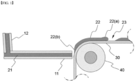
- FIG. 1 is a schematic diagram showing a process of discharging an electrode slurry on a current collector layer using a conventional electrode slurry coating apparatus.
- the electrode slurry coating apparatus has a structure in which an electrode slurry discharge flow path 11 for discharging an electrode slurry 21 through a slit formed on an interface between two dies is formed.
- the slurry supply flow path 12 is fluidly connected to the electrode slurry discharge flow path 11, through which the electrode slurry 21 is supplied.
- a current collector layer 30 formed of a metal foil passes the front of the electrode slurry discharge flow path 11 through a conveyor (not shown) driven by a rotating roller 40. The discharged electrode slurry is discharged on the current collector layer 30.
- the structure shown in FIG. 1 is a structure in which a coated part 22 and a non-coated part 23 are repeated on the current collector layer 30.
- the coated part 22 is a region where the electrode slurry is coated
- the non-coated part 23 is a region where the electrode slurry is not coated.
- the electrode slurry coating apparatus repeats the discharge and interruption of the electrode slurry 21. However, when the discharge of the interrupted electrode slurry is resumed, excessive load is taken into the electrode slurry discharge flow path 11, and thus excessive electrode slurry is discharged.
- the coating becomes thick as the excess electrode slurry is discharged, and in the case of the rear 22(b) of the coated part 22, the coating rapidly becomes thin as the discharge of the electrode slurry is interrupted.
- a conventional electrode slurry coating apparatus it is difficult to uniformly perform the electrode coating of a structure in which the coated part 22 and the non-coated part 23 are repeated.
- JP H09 108605A US 2012/097096 A1 , KR 2017 0101025 A , and JP 2015 097198A disclose a slot die coater for coating electrode active material on a current collector.
- the present invention was invented to solve the above problems, and an object of the present invention is to provide an electrode slurry coating apparatus and method including a pressure regulating member.
- An electrode slurry coating apparatus includes: an electrode slurry discharge flow path configured to discharge an electrode slurry through a slit formed on an interface between first and second dies; an electrode slurry storage tank configured to be fluidly connected to the electrode slurry discharge flow path and store the electrode slurry therein at a static pressure condition; and a static pressure opening and closing valve configured to be located on a flow path on which the electrode slurry discharge flow path is fluidly connected to the electrode slurry storage tank, wherein an opening or closing of the static pressure opening and closing valve is determined according to a difference between a pressure of the electrode slurry discharge flow path and an internal pressure of the electrode slurry storage tank.
- the electrode slurry discharge flow path and the electrode slurry storage tank face each other in a state in which the static pressure opening and closing valve is interposed therebetween.
- the static pressure opening and closing valve is configured to open when the pressure of the electrode slurry discharge flow path is greater than the internal pressure of the electrode slurry storage tank.
- the static pressure opening and closing valve includes a shielding member supported by an elastic force of an elastic body, and the shielding member is configured to open if a force of pressurizing the shielding member by the pressure of the electrode slurry discharge flow path exceeds a predetermined reference value.
- the electrode slurry coating apparatus further includes a pressure sensor configured to measure an internal pressure of the electrode slurry discharge flow path, and the static pressure opening and closing valve is configured to open if a pressure measured by the pressure sensor exceeds a predetermined reference value.
- the electrode slurry storage tank further includes an electrode slurry outlet flow path configured to discharge the stored electrode slurry if the internal pressure of the electrode slurry storage tank exceeds a predetermined reference value.
- the electrode slurry outlet flow path is fluidly connected to the electrode slurry discharge flow path.
- the electrode slurry discharged through the electrode slurry discharge flow path is discharged on a current collector layer which is moved by a conveyor.
- the electrode slurry coating apparatus further includes a discharge control pump configured to control a discharge amount of the electrode slurry through the electrode slurry discharge flow path.
- the electrode slurry coating apparatus further includes a discharge blocking member configured to control an opening and closing of the electrode slurry discharge flow path.
- the discharge blocking member is formed at an end of the electrode slurry discharge flow path.
- a method for coating an electrode slurry by using the above mentioned electrode slurry coating apparatus comprises: discharging an electrode slurry on a current collector layer through a slit-shaped electrode slurry discharge flow path formed on an interface between first and second dies, wherein during the discharging the electrode slurry, a process of starting a discharge of the electrode slurry and a process of interrupting the discharge of the electrode slurry are repeated at regular intervals, and wherein a pressure of the electrode slurry discharged is maintained constant by a pressure adjusting member formed on the slit-shaped electrode slurry discharge flow path.
- the pressure adjusting member includes: an electrode slurry storage tank configured to be fluidly connected to the electrode slurry discharge flow path and store the electrode slurry therein at a static pressure condition; and a static pressure opening and closing valve configured to be located on a flow path on which the electrode slurry discharge flow path is fluidly connected to the electrode slurry storage tank, wherein an opening or closing of the static pressure opening and closing valve is determined according to a difference between a pressure of the electrode slurry discharge flow path and an internal pressure of the electrode slurry storage tank.
- the static pressure opening and closing valve is configured to open when the pressure of the electrode slurry discharge flow path is greater than the internal pressure of the electrode slurry storage tank.
- the electrode slurry coating apparatus and the method according to the present invention include a pressure regulating member, so that the electrode slurry can be discharged at a constant pressure even when the coated part and the non-coated part are repeated on the current collector layer.
- the present invention relates to an electrode slurry coating apparatus, and in one example, the electrode slurry coating apparatus includes:
- the electrode slurry discharge flow path has a slit-shaped structure and refers to a flow path through which the electrode slurry is discharged through the interface between the blocks in a structure in which two or more blocks are engaged.
- the electrode slurry coating apparatus allows the electrode slurry to be continuously coated on the current collector which moves in one direction.
- the discharge can be performed in a form in which a coated part and a non-coated part are repeated in a machine direction (MD).
- MD machine direction
- the electrode slurry coating apparatus should repeat the discharge of the electrode slurry and interruption of the discharge.
- excessive load is taken to the electrode slurry discharge flow path.
- the electrode slurry is excessively discharged to the coating start portion of the coated part.
- the excessively discharged electrode slurry causes a phenomenon that the loading amount of the electrode slurry becomes uneven, which leads to the defect of products.
- the pressure adjusting member has a structure including an electrode slurry storage tank and a static pressure opening and closing valve described above.
- the electrode slurry discharge flow path and the electrode slurry storage tank face each other in a state in which the static pressure opening and closing valve is interposed therebetween.
- the electrode slurry storage tank according to the present invention is directly connected to an electrode slurry discharge flow path in a state in which a static pressure opening and closing valve is interposed. If a fluid connection line of a predetermined distance or more is formed, there is a limit in that it is difficult to immediately respond to the pressure change of the electrode slurry discharge flow path. Therefore, in the present invention, the static pressure opening and closing valve becomes part of the structure in which the electrode slurry discharge flow path is formed. Thus, in the present invention, it is possible to perform immediate pressure control by reflecting the pressure difference between the electrode slurry discharge flow path and the electrode slurry storage tank.
- the static pressure opening and closing valve has an open structure when the pressure of the electrode slurry discharge flow path is greater than the internal pressure of the electrode slurry storage tank.
- the static pressure opening and closing valve is configured to open, and a part of the electrode slurry which exists in the electrode slurry discharge flow path is leaked toward the electrode slurry storage tank. This solves the load taken to the electrode slurry discharge flow path.
- the static pressure opening and closing valve includes a shielding member supported by an elastic force of an elastic body, and the shielding member is configured to open if a force of pressurizing the shielding member by the pressure of the electrode slurry discharge flow path exceeds a predetermined reference value.
- the static pressure opening and closing valve includes a shielding member supported by a spring or a hinge structure with a spring.
- the electrode slurry coating apparatus further includes a sensor for measuring the internal pressure of the electrode slurry discharge flow path, and when the pressure measured by the pressure sensor exceeds a predetermined reference value, the static pressure opening and closing valve is configured to open.
- a pressure sensor for measuring the pressure of the electrode slurry discharge flow path is formed, thereby controlling the operation of the static pressure opening and closing valve.
- the electrode slurry storage tank further includes an electrode slurry outlet flow path configured to discharge the stored electrode slurry if the internal pressure of the electrode slurry storage tank exceeds a predetermined reference value.
- the electrode slurry storage tank has a predetermined structure, which maintains an internal pressure of, for example, a 14 kgf level, in a state where the electrode slurry is filled.
- the static pressure opening and closing valve is configured to open. As the static pressure opening and closing valve is configured to open, a part of the electrode slurry located in the electrode slurry discharge flow path is moved to the electrode slurry storage tank. Thus, the pressure of the electrode slurry discharge flow path is reduced.
- the electrode slurry storage tank may have a structure in which an electrode slurry outlet flow path is formed on the lower one side.
- the above-described static pressure opening and closing valve may be further formed on the electrode slurry outlet flow path.
- a pressure sensor for measuring the internal pressure may be formed in a electrode slurry storage tank, and if the pressure measured by the pressure sensor exceeds the reference value, the electrode slurry outlet flow path may be opened.
- an opening and closing valve of a structure including a shielding member supported by elastic force of an elastic body is located on the electrode slurry outlet flow path. The opening and closing valve with such an elastic body is advantageous in that a controller for opening and closing a separate sensor and valve is not required.
- the electrode slurry outlet flow path is fluidly connected to the electrode slurry discharge flow path. It is also possible to discard the electrode slurry discharged from the electrode slurry storage tank. However, it is possible to reuse the discharged electrode slurry by allowing the electrode slurry outlet flow path to be fluidly connected to the electrode slurry discharge flow path.
- the electrode slurry discharged through the electrode slurry discharge flow path is discharged on a current collector layer which is moved by a conveyor.
- the current collector layer may be formed of an aluminum foil or a copper foil.
- the current collector layer moves along the conveyor in one direction, and the electrode slurry coating apparatus discharges the electrode slurry so that the coated part and the non-coated part are repeated on the current collector layer.
- the electrode slurry coating apparatus further incudes a discharge control pump for controlling the discharge amount of the electrode slurry through the electrode slurry discharge flow path.
- the discharge control pump repeatedly performs a process of pressurization to discharge the electrode slurry and a process of interrupting the pressurization.
- the electrode slurry coating apparatus according to the present invention discharges the electrode slurry so that the coated part and the non-coated part are repeated on the current collector layer.
- the electrode slurry coating apparatus further includes a discharge blocking member for controlling opening and closing of the electrode slurry discharge flow path.
- the discharge blocking member is formed in the form of a bar that blocks, for example, a slit of the electrode slurry discharge flow path.
- the discharge blocking member closes the electrode slurry discharge flow path, the discharge of the electrode slurry by the electrode slurry coating apparatus is discontinued.
- the electrode slurry coating apparatus according to the present invention discharges the electrode slurry so that the coated part and the non-coated part are repeated on the current collector layer.
- the discharge blocking member is formed at an end of the electrode slurry discharge flow path.
- a method for coating an electrode slurry according to the present invention includes a step of discharging an electrode slurry on a current collector layer through a slit-shaped electrode slurry discharge flow path formed on an interface between first and second dies.
- a process of starting a discharge of the electrode slurry and a process of interrupting the discharge of the electrode slurry are repeated at regular intervals, and a pressure of the electrode slurry discharged is maintained constant by a pressure adjusting member formed on the slit-shaped electrode slurry discharge flow path.
- the electrode slurry coating method according to the present invention should repeat the discharge of the electrode slurry and interruption of the discharge.
- the electrode slurry if the discharge of the electrode slurry is resumed, excessive load is taken to the electrode slurry discharge flow path.
- the excessive load taken to the electrode slurry discharge flow path causes the electrode slurry to be excessively discharged to the coating start portion of the coated part.
- a pressure adjusting member for maintaining a pressure of the electrode slurry discharge flow path constant these problems are solved.
- the pressure adjusting member includes: an electrode slurry storage tank configured to be fluidly connected to the electrode slurry discharge flow path and store the electrode slurry therein at a static pressure condition; and a static pressure opening and closing valve configured to be located on a flow path on which the electrode slurry discharge flow path is fluidly connected to the electrode slurry storage tank, wherein an opening or closing of the static pressure opening and closing valve is determined according to a difference between a pressure of the electrode slurry discharge flow path and an internal pressure of the electrode slurry storage tank.
- the static pressure opening and closing valve has an open structure when the pressure of the electrode slurry discharge flow path is greater than the internal pressure of the electrode slurry storage tank.
- the static pressure opening and closing valve is configured to open, and a part of the electrode slurry which exists in the electrode slurry discharge flow path is leaked toward the electrode slurry storage tank. This solves the load taken to the electrode slurry discharge flow path.
- the static pressure opening and closing valve includes a shielding member supported by an elastic force of an elastic body, and the shielding member is configured to open if a force of pressurizing the shielding member by the pressure of the electrode slurry discharge flow path exceeds a predetermined reference value.
- the static pressure opening and closing valve includes a shielding member supported by elastic force of an elastic body
- the static pressure opening and closing valve includes a shielding member supported by a spring or a hinge structure with a spring.
- the present invention can control the opening and closing of the static pressure opening and closing valve in a non-powered manner and does not require a sensor for measuring the internal pressure of the electrode slurry discharge flow path.
- the electrode slurry coating method according to the present disclosure further includes a sensor for measuring the internal pressure of the electrode slurry discharge flow path, and when the pressure measured by the pressure sensor exceeds a predetermined reference value, the static pressure opening and closing valve is configured to open.
- the electrode slurry storage tank further includes an electrode slurry outlet flow path configured to discharge the stored electrode slurry if the internal pressure of the electrode slurry storage tank exceeds a predetermined reference value. Further, the electrode slurry outlet flow path is fluidly connected to the electrode slurry discharge flow path. It is also possible to discard the electrode slurry discharged from the electrode slurry storage tank. However, it is possible to reuse the discharged electrode slurry by allowing the electrode slurry outlet flow path to be fluidly connected to the electrode slurry discharge flow path.
- FIG. 2 is a schematic diagram showing a process of discharging an electrode slurry on a current collector layer using an electrode slurry coating apparatus according to an embodiment of the present invention.
- the electrode slurry coating apparatus has a structure in which an electrode slurry discharge flow path 111 for discharging an electrode slurry 121 through a slit formed on an interface between two dies is formed.
- the slurry supply flow path 112 is fluidly connected to the slurry discharge flow path 111, through which the electrode slurry 121 is supplied.
- a current collector layer 130 formed of a metal foil passes the front of the electrode slurry discharge flow path 111 through a conveyor (not shown) driven by a rotating roller 140.
- FIG. 2 shows a structure in which a coated part 122 and a non-coated part 123 are repeated on the current collector layer 130, and the electrode active material coating apparatus repeats the discharge of the electrode slurry and interruption of the discharge.
- the electrode active material coating apparatus repeats the discharge of the electrode slurry and interruption of the discharge.
- excessive load is taken into the electrode slurry discharge flow path 111, and thus excessive electrode slurry may be discharged.
- the present invention provides a pressure adjusting member for maintaining the load or pressure applied to the electrode slurry discharge flow path 111 constant.
- the pressure adjusting member includes an electrode slurry storage tank 150 where the electrode slurry 120 is filled and which maintain the internal pressure at a static pressure condition, and a static pressure opening and closing valve 151 where whether the static pressure opening and closing valve 151 is configured to open is determined according to a difference between the pressure of the electrode slurry discharge flow path 111 and the internal pressure of the electrode slurry storage tank 150.
- the electrode slurry storage tank 150 can be fluidly connected to the electrode slurry discharge flow path 111 and stores the electrode slurry 120 at a static pressure condition.
- the static pressure opening and closing valve 151 is located on the flow path where the electrode slurry discharge flow path 111 is fluidly connected to the electrode slurry storage tank 150, and whether the static pressure opening and closing valve 151 is configured to open is determined according to the difference between the pressure of the electrode slurry discharge flow path 111 and the internal pressure of the electrode slurry storage tank 150.
- the electrode slurry discharge flow path 111 and the electrode slurry storage tank 150 face each other in a state in which the static pressure opening and closing valve 151 is interposed therebetween. Further, the static pressure opening and closing valve 151 is configured to open when the pressure of the electrode slurry discharge flow path 111 is greater than the internal pressure of the electrode slurry storage tank 150.
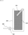
- FIGS. 3 and 4 are schematic diagrams illustrating an opening and closing process of a pressure adjusting member according to one embodiment of the present invention.
- the pressure adjusting member according to the present invention includes an electrode slurry storage tank 250 with an open upper surface, a static pressure opening and closing valve 251 which covers the upper surface of the electrode slurry storage tank 250, and an electrode slurry outlet flow path 260 formed at lower one side of the electrode slurry storage tank 250.
- the static pressure opening and closing valve 251 includes a plate-shaped shielding member supported by elastic force of an elastic body (e.g., a spring). Through this, the static pressure opening and closing valve 251 is configured to open when the pressure of the electrode slurry discharge flow path is greater than the internal pressure of the electrode slurry storage tank 250.
- the static pressure opening and closing valve 251 is configured to open when the pressure of the electrode slurry discharge flow path is greater than the internal pressure of the electrode slurry storage tank 250.
- the electrode slurry storage tank 250 maintains an internal pressure of 14 kgf, for example, in a state where the electrode slurry 220 is filled.
- the pressure of the electrode slurry discharge flow path exceeds 14 kgf, the pressure of the electrode slurry discharge flow path is transmitted to push and open the static pressure opening and closing valve 251.
- the static pressure opening and closing valve 251 is configured to open, a part of the electrode slurry located in the electrode slurry discharge flow path is moved to the electrode slurry storage tank 250. Thus, the pressure of the electrode slurry discharge flow path is reduced.
- the electrode slurry outlet flow path 260 is formed at lower one side of the electrode slurry storage tank 250.
- An outlet pump 261 is formed on the electrode slurry outlet flow path 260.
- the internal pressure of the electrode slurry storage tank 250 increases due to an electrode slurry which flows in as the static pressure opening and closing valve is configured to open. If the internal pressure of the electrode slurry storage tank 250 increases, part of the internal electrode slurry is discharged to the electrode slurry outlet flow path 260 by the outlet pump 261. It is also possible to form a separate static pressure opening and closing valve instead of the outlet pump 261.
- FIG. 5 is a schematic diagram illustrating an electrode slurry coating process according to an electrode slurry coating method according to one embodiment of the present invention.
- the method of coating an electrode slurry according to the present invention includes a step of discharging an electrode slurry 321 through a slit-shaped electrode slurry discharge flow path 311 formed on the interface between two dies.
- the electrode slurry 321 is supplied through the electrode slurry supply flow path 312. Further, in the step of discharging the electrode slurry 321, a process of starting the discharge of the electrode slurry 321 and a process of interrupting the discharge of the electrode slurry 321 are repeated.
- the pressure adjusting member includes an electrode slurry storage tank 350 with an open upper surface, a static pressure opening and closing valve 351 which covers the upper surface of the electrode slurry storage tank 350, and an electrode slurry outlet flow path 360 formed at lower one side of the electrode slurry storage tank 350.
- the current collector layer 330 is located on a conveyor moving by a rotating roller 340. The electrode slurry is coated on the current collector layer 330 so that the coated part 322 and the non-coated part 323 are repeated at regular intervals.
- the electrode slurry 320 is filled in the electrode slurry storage tank 350 to thereby maintain a constant pressure.
- the static pressure opening and closing valve 351 is configured to open, and part of the electrode slurry 321 existing in the electrode slurry discharge flow path 311 flows into the electrode slurry storage tank 350, thereby controlling pressure.
- the pressure in the electrode slurry storage tank 350 exceeds a predetermined level, part of the electrode slurry 320 filled inside is discharged to the electrode slurry outlet flow path 360 via the outlet pump 361.
- the electrode slurry discharged to the electrode slurry outlet flow path 360 is returned to the electrode slurry discharge flow path 311 or the electrode slurry supply flow path 312.
Landscapes
- Engineering & Computer Science (AREA)
- Manufacturing & Machinery (AREA)
- Chemical & Material Sciences (AREA)
- Chemical Kinetics & Catalysis (AREA)
- Electrochemistry (AREA)
- General Chemical & Material Sciences (AREA)
- Physics & Mathematics (AREA)
- Fluid Mechanics (AREA)
- Battery Electrode And Active Subsutance (AREA)
- Coating Apparatus (AREA)
- Application Of Or Painting With Fluid Materials (AREA)
Description
- This application claims the benefit of priority based on
Korean Patent Application No. 10-2019-0143427, filed on November 11, 2019 - The present invention relates to an electrode slurry coating apparatus and method including a pressure regulating member.
- With the increase in technology development and demand for mobile devices, the demand for secondary batteries is also rapidly increasing. Among them, lithium secondary batteries are widely used as an energy source for various electronic products as well as various mobile devices because of their high energy density and high operating voltage and excellent storage and lifetime characteristics.
- In addition, the secondary battery has a structure in which an electrode assembly including a positive electrode, a negative electrode, and a separator interposed between the positive electrode and the negative electrode is accommodated in a battery case in a state impregnated with an electrolyte solution. The positive electrode and the negative electrode are coated with an electrode slurry containing an active material on a current collector formed of, for example, a metal foil, such as aluminum or copper.
-
FIG. 1 is a schematic diagram showing a process of discharging an electrode slurry on a current collector layer using a conventional electrode slurry coating apparatus. Referring toFIG. 1 , the electrode slurry coating apparatus has a structure in which an electrode slurrydischarge flow path 11 for discharging anelectrode slurry 21 through a slit formed on an interface between two dies is formed. In addition, the slurrysupply flow path 12 is fluidly connected to the electrode slurrydischarge flow path 11, through which theelectrode slurry 21 is supplied. Acurrent collector layer 30 formed of a metal foil passes the front of the electrode slurrydischarge flow path 11 through a conveyor (not shown) driven by a rotatingroller 40. The discharged electrode slurry is discharged on thecurrent collector layer 30. The structure shown inFIG. 1 is a structure in which a coatedpart 22 and anon-coated part 23 are repeated on thecurrent collector layer 30. The coatedpart 22 is a region where the electrode slurry is coated, and thenon-coated part 23 is a region where the electrode slurry is not coated. The electrode slurry coating apparatus repeats the discharge and interruption of theelectrode slurry 21. However, when the discharge of the interrupted electrode slurry is resumed, excessive load is taken into the electrode slurrydischarge flow path 11, and thus excessive electrode slurry is discharged. As a result, in the case of the front 22(a) of the coatedpart 22, the coating becomes thick as the excess electrode slurry is discharged, and in the case of the rear 22(b) of the coatedpart 22, the coating rapidly becomes thin as the discharge of the electrode slurry is interrupted. As such, when a conventional electrode slurry coating apparatus is used, it is difficult to uniformly perform the electrode coating of a structure in which the coatedpart 22 and the non-coatedpart 23 are repeated. -
JP H09 108605A US 2012/097096 A1 ,KR 2017 0101025 A JP 2015 097198A - The present invention was invented to solve the above problems, and an object of the present invention is to provide an electrode slurry coating apparatus and method including a pressure regulating member.
- The present invention provides an electrode slurry coating apparatus as defined in the appended set of claims. An electrode slurry coating apparatus according to the present invention includes: an electrode slurry discharge flow path configured to discharge an electrode slurry through a slit formed on an interface between first and second dies; an electrode slurry storage tank configured to be fluidly connected to the electrode slurry discharge flow path and store the electrode slurry therein at a static pressure condition; and a static pressure opening and closing valve configured to be located on a flow path on which the electrode slurry discharge flow path is fluidly connected to the electrode slurry storage tank, wherein an opening or closing of the static pressure opening and closing valve is determined according to a difference between a pressure of the electrode slurry discharge flow path and an internal pressure of the electrode slurry storage tank.
- In a specific example, the electrode slurry discharge flow path and the electrode slurry storage tank face each other in a state in which the static pressure opening and closing valve is interposed therebetween.
- In one example, the static pressure opening and closing valve is configured to open when the pressure of the electrode slurry discharge flow path is greater than the internal pressure of the electrode slurry storage tank.
- According to the invention, the static pressure opening and closing valve includes a shielding member supported by an elastic force of an elastic body, and the shielding member is configured to open if a force of pressurizing the shielding member by the pressure of the electrode slurry discharge flow path exceeds a predetermined reference value.
- In another disclosed but not claimed specific example, the electrode slurry coating apparatus further includes a pressure sensor configured to measure an internal pressure of the electrode slurry discharge flow path, and the static pressure opening and closing valve is configured to open if a pressure measured by the pressure sensor exceeds a predetermined reference value.
- In one example, the electrode slurry storage tank further includes an electrode slurry outlet flow path configured to discharge the stored electrode slurry if the internal pressure of the electrode slurry storage tank exceeds a predetermined reference value.
- In a specific example, the electrode slurry outlet flow path is fluidly connected to the electrode slurry discharge flow path.
- In one example, the electrode slurry discharged through the electrode slurry discharge flow path is discharged on a current collector layer which is moved by a conveyor.
- In another example, the electrode slurry coating apparatus further includes a discharge control pump configured to control a discharge amount of the electrode slurry through the electrode slurry discharge flow path.
- In one example, the electrode slurry coating apparatus further includes a discharge blocking member configured to control an opening and closing of the electrode slurry discharge flow path.
- In a specific example, the discharge blocking member is formed at an end of the electrode slurry discharge flow path.
- Further, the present invention provides a method, which is defined in the appended set of claims, for coating an electrode slurry by using the above described electrode slurry coating apparatus. A method for coating an electrode slurry by using the above mentioned electrode slurry coating apparatus according to the present invention comprises:
discharging an electrode slurry on a current collector layer through a slit-shaped electrode slurry discharge flow path formed on an interface between first and second dies, wherein during the discharging the electrode slurry, a process of starting a discharge of the electrode slurry and a process of interrupting the discharge of the electrode slurry are repeated at regular intervals, and wherein a pressure of the electrode slurry discharged is maintained constant by a pressure adjusting member formed on the slit-shaped electrode slurry discharge flow path. - In one example, the pressure adjusting member includes: an electrode slurry storage tank configured to be fluidly connected to the electrode slurry discharge flow path and store the electrode slurry therein at a static pressure condition; and a static pressure opening and closing valve configured to be located on a flow path on which the electrode slurry discharge flow path is fluidly connected to the electrode slurry storage tank, wherein an opening or closing of the static pressure opening and closing valve is determined according to a difference between a pressure of the electrode slurry discharge flow path and an internal pressure of the electrode slurry storage tank.
- In a specific example, the static pressure opening and closing valve is configured to open when the pressure of the electrode slurry discharge flow path is greater than the internal pressure of the electrode slurry storage tank.
- The electrode slurry coating apparatus and the method according to the present invention include a pressure regulating member, so that the electrode slurry can be discharged at a constant pressure even when the coated part and the non-coated part are repeated on the current collector layer.
-
-
FIG. 1 is a schematic diagram showing a process of discharging an electrode slurry on a current collector layer using a conventional electrode slurry coating apparatus. -
FIG. 2 is a schematic diagram showing a process of discharging an electrode slurry on a current collector layer using an electrode slurry coating apparatus according to an embodiment of the present invention. -
FIGS. 3 and4 are schematic diagrams illustrating an opening and closing process of a pressure adjusting member according to one embodiment of the present invention. -
FIG. 5 is a schematic diagram illustrating an electrode slurry coating process according to an electrode slurry coating method according to one embodiment of the present invention. - Hereinafter, the present invention will be described in detail with reference to the drawings. The terms and words used in the present specification and claims should not be construed as limited to ordinary or dictionary terms and the inventor may properly define the concept of the terms in order to best describe its invention. The terms and words should be construed as meaning and concept consistent with the technical idea of the present invention.
- The present invention relates to an electrode slurry coating apparatus, and in one example, the electrode slurry coating apparatus includes:
- an electrode slurry discharge flow path configured to discharge an electrode slurry through a slit formed on an interface between first and second dies;
- an electrode slurry storage tank configured to be fluidly connected to the electrode slurry discharge flow path and store the electrode slurry therein at a static pressure condition; and
- a static pressure opening and closing valve configured to be located on a flow path on which the electrode slurry discharge flow path is fluidly connected to the electrode slurry storage tank, wherein an opening or closing of the static pressure opening and closing valve is determined according to a difference between a pressure of the electrode slurry discharge flow path and an internal pressure of the electrode slurry storage tank, the static pressure opening and closing valve (151) includes
- a shielding member supported by an elastic force of an elastic body, and the shielding member is configured to open if a force of pressurizing the shielding member by the pressure of the electrode slurry discharge flow path (111) exceeds a predetermined reference value.
- The electrode slurry discharge flow path has a slit-shaped structure and refers to a flow path through which the electrode slurry is discharged through the interface between the blocks in a structure in which two or more blocks are engaged.
- The electrode slurry coating apparatus allows the electrode slurry to be continuously coated on the current collector which moves in one direction. When coating the electrode slurry on a current collector layer using the electrode slurry coating apparatus, the discharge can be performed in a form in which a coated part and a non-coated part are repeated in a machine direction (MD). In this case, the electrode slurry coating apparatus should repeat the discharge of the electrode slurry and interruption of the discharge. However, when the coating of the electrode slurry interrupted in the electrode slurry coating apparatus is resumed, excessive load is taken to the electrode slurry discharge flow path. When an excessive load is applied to the electrode slurry discharge flow path, the electrode slurry is excessively discharged to the coating start portion of the coated part. The excessively discharged electrode slurry causes a phenomenon that the loading amount of the electrode slurry becomes uneven, which leads to the defect of products. In the present invention, by including a pressure adjusting member for maintaining a pressure of the electrode slurry discharge flow path constant, these problems are solved. The pressure adjusting member has a structure including an electrode slurry storage tank and a static pressure opening and closing valve described above.
- In one example, the electrode slurry discharge flow path and the electrode slurry storage tank face each other in a state in which the static pressure opening and closing valve is interposed therebetween. The electrode slurry storage tank according to the present invention is directly connected to an electrode slurry discharge flow path in a state in which a static pressure opening and closing valve is interposed. If a fluid connection line of a predetermined distance or more is formed, there is a limit in that it is difficult to immediately respond to the pressure change of the electrode slurry discharge flow path. Therefore, in the present invention, the static pressure opening and closing valve becomes part of the structure in which the electrode slurry discharge flow path is formed. Thus, in the present invention, it is possible to perform immediate pressure control by reflecting the pressure difference between the electrode slurry discharge flow path and the electrode slurry storage tank.
- In one embodiment, the static pressure opening and closing valve has an open structure when the pressure of the electrode slurry discharge flow path is greater than the internal pressure of the electrode slurry storage tank. When the coating of the electrode slurry interrupted in the electrode slurry coating apparatus is resumed, excessive load is taken to the electrode slurry discharge flow path, thereby discharging a lot of electrode slurry. In the present invention, excessive loads in the electrode slurry discharge flow path can be efficiently resolved. That is, if an excessive load is applied to the electrode slurry discharge flow path, the static pressure opening and closing valve is configured to open, and a part of the electrode slurry which exists in the electrode slurry discharge flow path is leaked toward the electrode slurry storage tank. This solves the load taken to the electrode slurry discharge flow path.
- According to the invention, the static pressure opening and closing valve includes a shielding member supported by an elastic force of an elastic body, and the shielding member is configured to open if a force of pressurizing the shielding member by the pressure of the electrode slurry discharge flow path exceeds a predetermined reference value. In this case, the static pressure opening and closing valve includes a shielding member supported by a spring or a hinge structure with a spring. Thus, the present invention can control the opening and closing of the static pressure opening and closing valve in a non-powered manner and does not require a sensor for measuring the internal pressure of the electrode slurry discharge flow path.
- In another disclosed but not claimed specific embodiment, the electrode slurry coating apparatus according to the present disclosure further includes a sensor for measuring the internal pressure of the electrode slurry discharge flow path, and when the pressure measured by the pressure sensor exceeds a predetermined reference value, the static pressure opening and closing valve is configured to open. In this case, a pressure sensor for measuring the pressure of the electrode slurry discharge flow path is formed, thereby controlling the operation of the static pressure opening and closing valve.
- In one specific example, the electrode slurry storage tank further includes an electrode slurry outlet flow path configured to discharge the stored electrode slurry if the internal pressure of the electrode slurry storage tank exceeds a predetermined reference value. The electrode slurry storage tank has a predetermined structure, which maintains an internal pressure of, for example, a 14 kgf level, in a state where the electrode slurry is filled. When the pressure of the electrode slurry discharge flow path exceeds 14 kgf, the static pressure opening and closing valve is configured to open. As the static pressure opening and closing valve is configured to open, a part of the electrode slurry located in the electrode slurry discharge flow path is moved to the electrode slurry storage tank. Thus, the pressure of the electrode slurry discharge flow path is reduced. However, the internal pressure of the electrode slurry storage tank increases due to the inflowing electrode slurry. In order to solve this, the electrode slurry storage tank may have a structure in which an electrode slurry outlet flow path is formed on the lower one side. The above-described static pressure opening and closing valve may be further formed on the electrode slurry outlet flow path.
- In a disclosed but not claimed example, a pressure sensor for measuring the internal pressure may be formed in a electrode slurry storage tank, and if the pressure measured by the pressure sensor exceeds the reference value, the electrode slurry outlet flow path may be opened. Alternatively, according to the invention an opening and closing valve of a structure including a shielding member supported by elastic force of an elastic body is located on the electrode slurry outlet flow path. The opening and closing valve with such an elastic body is advantageous in that a controller for opening and closing a separate sensor and valve is not required.
- In one embodiment, the electrode slurry outlet flow path is fluidly connected to the electrode slurry discharge flow path. It is also possible to discard the electrode slurry discharged from the electrode slurry storage tank. However, it is possible to reuse the discharged electrode slurry by allowing the electrode slurry outlet flow path to be fluidly connected to the electrode slurry discharge flow path.
- In one example, the electrode slurry discharged through the electrode slurry discharge flow path is discharged on a current collector layer which is moved by a conveyor. The current collector layer may be formed of an aluminum foil or a copper foil. For example, the current collector layer moves along the conveyor in one direction, and the electrode slurry coating apparatus discharges the electrode slurry so that the coated part and the non-coated part are repeated on the current collector layer.
- In one specific embodiment, the electrode slurry coating apparatus further incudes a discharge control pump for controlling the discharge amount of the electrode slurry through the electrode slurry discharge flow path. The discharge control pump repeatedly performs a process of pressurization to discharge the electrode slurry and a process of interrupting the pressurization. Thus, the electrode slurry coating apparatus according to the present invention discharges the electrode slurry so that the coated part and the non-coated part are repeated on the current collector layer.
- In another specific embodiment, the electrode slurry coating apparatus further includes a discharge blocking member for controlling opening and closing of the electrode slurry discharge flow path. The discharge blocking member is formed in the form of a bar that blocks, for example, a slit of the electrode slurry discharge flow path. When the discharge blocking member closes the electrode slurry discharge flow path, the discharge of the electrode slurry by the electrode slurry coating apparatus is discontinued. Thus, the electrode slurry coating apparatus according to the present invention discharges the electrode slurry so that the coated part and the non-coated part are repeated on the current collector layer. For example, the discharge blocking member is formed at an end of the electrode slurry discharge flow path.
- The present invention also provides an electrode slurry coating method using the electrode slurry coating apparatus described above. In one example, a method for coating an electrode slurry according to the present invention includes a step of discharging an electrode slurry on a current collector layer through a slit-shaped electrode slurry discharge flow path formed on an interface between first and second dies.
- In the step of discharging the electrode slurry, a process of starting a discharge of the electrode slurry and a process of interrupting the discharge of the electrode slurry are repeated at regular intervals, and
a pressure of the electrode slurry discharged is maintained constant by a pressure adjusting member formed on the slit-shaped electrode slurry discharge flow path. - In the present invention, by repeating a step of starting the discharge of the electrode slurry and a step of interrupting the discharge of the electrode slurry, it is possible to coat the electrode slurry on the current collector layer, with a pattern in which the coated part and the non-coated part are repeated in MD direction. In this case, the electrode slurry coating method according to the present invention should repeat the discharge of the electrode slurry and interruption of the discharge. However, when the coating the electrode slurry, if the discharge of the electrode slurry is resumed, excessive load is taken to the electrode slurry discharge flow path. The excessive load taken to the electrode slurry discharge flow path causes the electrode slurry to be excessively discharged to the coating start portion of the coated part. In the present invention, by including a pressure adjusting member for maintaining a pressure of the electrode slurry discharge flow path constant, these problems are solved.
- In one example, the pressure adjusting member includes: an electrode slurry storage tank configured to be fluidly connected to the electrode slurry discharge flow path and store the electrode slurry therein at a static pressure condition; and a static pressure opening and closing valve configured to be located on a flow path on which the electrode slurry discharge flow path is fluidly connected to the electrode slurry storage tank, wherein an opening or closing of the static pressure opening and closing valve is determined according to a difference between a pressure of the electrode slurry discharge flow path and an internal pressure of the electrode slurry storage tank.
- In one specific embodiment, the static pressure opening and closing valve has an open structure when the pressure of the electrode slurry discharge flow path is greater than the internal pressure of the electrode slurry storage tank. When the coating of the electrode slurry interrupted in the electrode slurry coating method is resumed, excessive load is taken to the electrode slurry discharge flow path, thereby discharging a lot of electrode slurry. In the present invention, excessive loads in the electrode slurry discharge flow path can be efficiently resolved. That is, if an excessive load is applied to the electrode slurry discharge flow path, the static pressure opening and closing valve is configured to open, and a part of the electrode slurry which exists in the electrode slurry discharge flow path is leaked toward the electrode slurry storage tank. This solves the load taken to the electrode slurry discharge flow path.
- According to the invention, the static pressure opening and closing valve includes a shielding member supported by an elastic force of an elastic body, and the shielding member is configured to open if a force of pressurizing the shielding member by the pressure of the electrode slurry discharge flow path exceeds a predetermined reference value. If the static pressure opening and closing valve includes a shielding member supported by elastic force of an elastic body, the static pressure opening and closing valve includes a shielding member supported by a spring or a hinge structure with a spring. As such, the present invention can control the opening and closing of the static pressure opening and closing valve in a non-powered manner and does not require a sensor for measuring the internal pressure of the electrode slurry discharge flow path.
- In another disclosed but not claimed specific embodiment, the electrode slurry coating method according to the present disclosure further includes a sensor for measuring the internal pressure of the electrode slurry discharge flow path, and when the pressure measured by the pressure sensor exceeds a predetermined reference value, the static pressure opening and closing valve is configured to open.
- In one example, the electrode slurry storage tank further includes an electrode slurry outlet flow path configured to discharge the stored electrode slurry if the internal pressure of the electrode slurry storage tank exceeds a predetermined reference value. Further, the electrode slurry outlet flow path is fluidly connected to the electrode slurry discharge flow path. It is also possible to discard the electrode slurry discharged from the electrode slurry storage tank. However, it is possible to reuse the discharged electrode slurry by allowing the electrode slurry outlet flow path to be fluidly connected to the electrode slurry discharge flow path.
- In the present invention, a description of the electrode slurry coating apparatus mentioned above is also applicable to the electrode slurry coating method, and a redundant description about this is omitted here.
- Hereinafter, the present invention will be described in more detail through drawings and examples.
-
FIG. 2 is a schematic diagram showing a process of discharging an electrode slurry on a current collector layer using an electrode slurry coating apparatus according to an embodiment of the present invention. Referring toFIG. 2 , the electrode slurry coating apparatus has a structure in which an electrode slurrydischarge flow path 111 for discharging anelectrode slurry 121 through a slit formed on an interface between two dies is formed. In addition, the slurrysupply flow path 112 is fluidly connected to the slurrydischarge flow path 111, through which theelectrode slurry 121 is supplied. Acurrent collector layer 130 formed of a metal foil passes the front of the electrode slurrydischarge flow path 111 through a conveyor (not shown) driven by arotating roller 140. The discharged electrode slurry is discharged on thecurrent collector layer 130.FIG. 2 shows a structure in which acoated part 122 and anon-coated part 123 are repeated on thecurrent collector layer 130, and the electrode active material coating apparatus repeats the discharge of the electrode slurry and interruption of the discharge. However, when the discharge of the interrupted electrode slurry is resumed, excessive load is taken into the electrode slurrydischarge flow path 111, and thus excessive electrode slurry may be discharged. - The present invention provides a pressure adjusting member for maintaining the load or pressure applied to the electrode slurry
discharge flow path 111 constant. The pressure adjusting member includes an electrodeslurry storage tank 150 where theelectrode slurry 120 is filled and which maintain the internal pressure at a static pressure condition, and a static pressure opening and closingvalve 151 where whether the static pressure opening and closingvalve 151 is configured to open is determined according to a difference between the pressure of the electrode slurrydischarge flow path 111 and the internal pressure of the electrodeslurry storage tank 150. The electrodeslurry storage tank 150 can be fluidly connected to the electrode slurrydischarge flow path 111 and stores theelectrode slurry 120 at a static pressure condition. Further, the static pressure opening and closingvalve 151 is located on the flow path where the electrode slurrydischarge flow path 111 is fluidly connected to the electrodeslurry storage tank 150, and whether the static pressure opening and closingvalve 151 is configured to open is determined according to the difference between the pressure of the electrode slurrydischarge flow path 111 and the internal pressure of the electrodeslurry storage tank 150. - Specifically, the electrode slurry
discharge flow path 111 and the electrodeslurry storage tank 150 face each other in a state in which the static pressure opening and closingvalve 151 is interposed therebetween. Further, the static pressure opening and closingvalve 151 is configured to open when the pressure of the electrode slurrydischarge flow path 111 is greater than the internal pressure of the electrodeslurry storage tank 150. -
FIGS. 3 and4 are schematic diagrams illustrating an opening and closing process of a pressure adjusting member according to one embodiment of the present invention. Referring toFIG. 3 , the pressure adjusting member according to the present invention includes an electrodeslurry storage tank 250 with an open upper surface, a static pressure opening and closingvalve 251 which covers the upper surface of the electrodeslurry storage tank 250, and an electrode slurryoutlet flow path 260 formed at lower one side of the electrodeslurry storage tank 250. The static pressure opening and closingvalve 251 includes a plate-shaped shielding member supported by elastic force of an elastic body (e.g., a spring). Through this, the static pressure opening and closingvalve 251 is configured to open when the pressure of the electrode slurry discharge flow path is greater than the internal pressure of the electrodeslurry storage tank 250. - Referring to
FIG. 4 , the static pressure opening and closingvalve 251 is configured to open when the pressure of the electrode slurry discharge flow path is greater than the internal pressure of the electrodeslurry storage tank 250. The electrodeslurry storage tank 250 maintains an internal pressure of 14 kgf, for example, in a state where theelectrode slurry 220 is filled. When the pressure of the electrode slurry discharge flow path exceeds 14 kgf, the pressure of the electrode slurry discharge flow path is transmitted to push and open the static pressure opening and closingvalve 251. As the static pressure opening and closingvalve 251 is configured to open, a part of the electrode slurry located in the electrode slurry discharge flow path is moved to the electrodeslurry storage tank 250. Thus, the pressure of the electrode slurry discharge flow path is reduced. - Further, the electrode slurry
outlet flow path 260 is formed at lower one side of the electrodeslurry storage tank 250. Anoutlet pump 261 is formed on the electrode slurryoutlet flow path 260. As mentioned above, the internal pressure of the electrodeslurry storage tank 250 increases due to an electrode slurry which flows in as the static pressure opening and closing valve is configured to open. If the internal pressure of the electrodeslurry storage tank 250 increases, part of the internal electrode slurry is discharged to the electrode slurryoutlet flow path 260 by theoutlet pump 261. It is also possible to form a separate static pressure opening and closing valve instead of theoutlet pump 261. -
FIG. 5 is a schematic diagram illustrating an electrode slurry coating process according to an electrode slurry coating method according to one embodiment of the present invention. Referring toFIG. 5 , the method of coating an electrode slurry according to the present invention includes a step of discharging anelectrode slurry 321 through a slit-shaped electrode slurrydischarge flow path 311 formed on the interface between two dies. Theelectrode slurry 321 is supplied through the electrode slurrysupply flow path 312. Further, in the step of discharging theelectrode slurry 321, a process of starting the discharge of theelectrode slurry 321 and a process of interrupting the discharge of theelectrode slurry 321 are repeated. At this time, the pressure of theelectrode slurry 321 discharged is maintained constant by the pressure adjusting member formed on the slit-shaped electrode slurrydischarge flow path 311. The pressure adjusting member includes an electrodeslurry storage tank 350 with an open upper surface, a static pressure opening and closingvalve 351 which covers the upper surface of the electrodeslurry storage tank 350, and an electrode slurryoutlet flow path 360 formed at lower one side of the electrodeslurry storage tank 350. Thecurrent collector layer 330 is located on a conveyor moving by arotating roller 340. The electrode slurry is coated on thecurrent collector layer 330 so that thecoated part 322 and thenon-coated part 323 are repeated at regular intervals. - Further, the
electrode slurry 320 is filled in the electrodeslurry storage tank 350 to thereby maintain a constant pressure. When the pressure of the electrode slurrydischarge flow path 311 increases, the static pressure opening and closingvalve 351 is configured to open, and part of theelectrode slurry 321 existing in the electrode slurrydischarge flow path 311 flows into the electrodeslurry storage tank 350, thereby controlling pressure. When the pressure in the electrodeslurry storage tank 350 exceeds a predetermined level, part of theelectrode slurry 320 filled inside is discharged to the electrode slurryoutlet flow path 360 via theoutlet pump 361. - In some cases, the electrode slurry discharged to the electrode slurry
outlet flow path 360 is returned to the electrode slurrydischarge flow path 311 or the electrode slurrysupply flow path 312. - In the above, the present invention has been described in more detail through the drawings and examples. Accordingly, the embodiments described in the specification and the configurations described in the drawings are only the most preferred embodiments of the present invention, and do not represent all of the technical ideas of the present invention. It is to be understood that there may be various equivalents and variations in place of them at the time of filing the present application.
-
- 11, 111, 311: electrode slurry discharge flow path
- 12, 112, 312: electrode slurry supply flow path
- 21, 121, 220, 320, 321: Electrode Slurry
- 22, 22(a), 22(b), 122, 322: coated part
- 23, 123, 323: non-coated part
- 30, 130, 330: current collector layer
- 40, 140, 340: roller
- 150, 250, 350: electrode slurry storage tank
- 151, 251, 351: static pressure opening and closing valve
- 260, 360: electrode slurry outlet flow path
- 261, 361: outlet pump
Claims (11)
- An electrode slurry coating apparatus, comprising:an electrode slurry discharge flow path (111) configured to discharge an electrode slurry (121) through a slit formed on an interface between first and second dies;an electrode slurry storage tank (150) configured to be fluidly connected to the electrode slurry discharge flow path (111) and store the electrode slurry (121) therein at a static pressure condition; anda static pressure opening and closing valve (151) configured to be located on a flow path on which the electrode slurry discharge flow path (111) is fluidly connected to the electrode slurry storage tank (150),wherein an opening or closing of the static pressure opening and closing valve (151) is determined according to a difference between a pressure of the electrode slurry discharge flow path (111) and an internal pressure of the electrode slurry storage tank (150),characterized in thatthe static pressure opening and closing valve (151) includes a shielding member supported by an elastic force of an elastic body, andthe shielding member is configured to open if a force of pressurizing the shielding member by the pressure of the electrode slurry discharge flow path (111) exceeds a predetermined reference value.
- The electrode slurry coating apparatus of claim 1, wherein the electrode slurry discharge flow path (111) and the electrode slurry storage tank (150) face each other in a state in which the static pressure opening and closing valve (151) is interposed therebetween.
- The electrode slurry coating apparatus of claim 1, wherein the static pressure opening and closing valve (151) is configured to open when the pressure of the electrode slurry discharge flow path (111) is greater than the internal pressure of the electrode slurry storage tank (150).
- The electrode slurry coating apparatus of claim 1, wherein the electrode slurry storage tank (150) further includes an electrode slurry outlet flow path (260) configured to discharge the stored electrode slurry (120) if the internal pressure of the electrode slurry storage tank (150) exceeds a predetermined reference value.
- The electrode slurry coating apparatus of claim 4, wherein the electrode slurry outlet flow path (260) is fluidly connected to the electrode slurry discharge flow path (111).
- The electrode slurry coating apparatus of claim 1, further comprising a discharge control pump configured to control a discharge amount of the electrode slurry through the electrode slurry discharge flow path (111).
- The electrode slurry coating apparatus of claim 1, further comprising a discharge blocking member configured to control an opening and closing of the electrode slurry discharge flow path.
- The electrode slurry coating apparatus of claim 7, wherein the discharge blocking member is formed at an end of the electrode slurry discharge flow path (111).
- A method for coating an electrode slurry by using the electrode slurry coating apparatus of claim 1, the method comprising:discharging an electrode slurry on a current collector layer (130) through a slit-shaped electrode slurry discharge flow path (111) formed on an interface between first and second dies,wherein during the discharging the electrode slurry (121), a process of starting a discharge of the electrode slurry and a process of interrupting the discharge of the electrode slurry are repeated at regular intervals, andwherein a pressure of the electrode slurry discharged is maintained constant by a pressure adjusting member formed on the slit-shaped electrode slurry discharge flow path (111).
- The method of claim 9, wherein the pressure adjusting member comprises:an electrode slurry storage tank (150) configured to be fluidly connected to the electrode slurry discharge flow path (111) and store the electrode slurry therein at a static pressure condition; anda static pressure opening and closing valve (151) configured to be located on a flow path on which the electrode slurry discharge flow path (111) is fluidly connected to the electrode slurry storage tank (150),wherein an opening or closing of the static pressure opening and closing valve (151) is determined according to a difference between a pressure of the electrode slurry discharge flow path (111) and an internal pressure of the electrode slurry storage tank (150).
- The method of claim 10 = , wherein the static pressure opening and closing valve (151) is configured to open when the pressure of the electrode slurry discharge flow path (111) is greater than the internal pressure of the electrode slurry storage tank (150).
Applications Claiming Priority (2)
| Application Number | Priority Date | Filing Date | Title |
|---|---|---|---|
| KR1020190143427A KR102636808B1 (en) | 2019-11-11 | 2019-11-11 | Electrode slurry coating device and method comprising pressure adjusting member |
| PCT/KR2020/015568 WO2021096169A1 (en) | 2019-11-11 | 2020-11-09 | Electrode slurry coating method and apparatus comprising pressure adjustment member |
Publications (3)
| Publication Number | Publication Date |
|---|---|
| EP3900844A1 EP3900844A1 (en) | 2021-10-27 |
| EP3900844A4 EP3900844A4 (en) | 2022-05-18 |
| EP3900844B1 true EP3900844B1 (en) | 2025-02-12 |
Family
ID=75911414
Family Applications (1)
| Application Number | Title | Priority Date | Filing Date |
|---|---|---|---|
| EP20887906.4A Active EP3900844B1 (en) | 2019-11-11 | 2020-11-09 | Electrode slurry coating method and apparatus comprising pressure adjustment member |
Country Status (9)
| Country | Link |
|---|---|
| US (2) | US12278358B2 (en) |
| EP (1) | EP3900844B1 (en) |
| JP (1) | JP7252364B2 (en) |
| KR (1) | KR102636808B1 (en) |
| CN (1) | CN113613797A (en) |
| ES (1) | ES3015243T3 (en) |
| HU (1) | HUE070378T2 (en) |
| PL (1) | PL3900844T3 (en) |
| WO (1) | WO2021096169A1 (en) |
Families Citing this family (3)
| Publication number | Priority date | Publication date | Assignee | Title |
|---|---|---|---|---|
| CN116419803A (en) * | 2021-06-16 | 2023-07-11 | 株式会社Lg新能源 | Slurry circulation system for electrode coating capable of circulating slurry when line stop occurs and slurry circulation method for electrode coating using the slurry circulation system |
| KR102862699B1 (en) * | 2021-08-27 | 2025-09-19 | 주식회사 엘지에너지솔루션 | Electrode slurry coating device for secondary battery and electrode slurry coating method using the same |
| CN117936712B (en) * | 2024-03-21 | 2024-07-19 | 潍柴动力股份有限公司 | A method for improving the density of a positive electrode sheet of a solid-state battery and a solid-state battery |
Family Cites Families (33)
| Publication number | Priority date | Publication date | Assignee | Title |
|---|---|---|---|---|
| JPH06190845A (en) | 1992-12-28 | 1994-07-12 | Hitachi Chem Co Ltd | Method and device for producing sheet |
| JP3744574B2 (en) | 1995-10-20 | 2006-02-15 | Tdk株式会社 | Intermittent application method |
| JP4486222B2 (en) | 2000-06-02 | 2010-06-23 | 本田技研工業株式会社 | Viscous material applicator |
| JP2002028553A (en) | 2000-07-12 | 2002-01-29 | Sony Chem Corp | Coating apparatus |
| JP2002143755A (en) | 2000-11-13 | 2002-05-21 | Konica Corp | Coating method |
| KR200340149Y1 (en) * | 2003-10-27 | 2004-01-31 | 서훈 | Check valve of painting apparatus for low pressure spray gun |
| JP4315787B2 (en) | 2003-11-18 | 2009-08-19 | 大日本スクリーン製造株式会社 | Substrate processing apparatus, and structure for determining liquid filling degree and gas mixing degree in filling object |
| JP2006043505A (en) | 2004-07-30 | 2006-02-16 | Matsushita Electric Ind Co Ltd | Application nozzle |
| KR100709229B1 (en) | 2006-02-21 | 2007-04-18 | 삼성에스디아이 주식회사 | Coater of Slurry Coating Equipment |
| JP4377904B2 (en) | 2006-10-31 | 2009-12-02 | 株式会社東芝 | Electrode manufacturing method and non-aqueous electrolyte battery manufacturing method |
| JP4975454B2 (en) * | 2007-01-25 | 2012-07-11 | 中外炉工業株式会社 | Coating device and bubble detection method in coating device |
| CN101883639B (en) | 2007-12-10 | 2013-01-23 | 丰田自动车株式会社 | Coating apparatus and method of applying coating liquid |
| TWI496621B (en) | 2010-10-26 | 2015-08-21 | Prologium Technology Co | Coating head and coating machine using the same |
| KR101285999B1 (en) | 2011-04-14 | 2013-07-15 | 삼성에스디아이 주식회사 | Coating Apparatus for Electrode Plate of Secondary Battery |
| US8771793B2 (en) | 2011-04-15 | 2014-07-08 | Roche Diagnostics Operations, Inc. | Vacuum assisted slot die coating techniques |
| JP5691874B2 (en) * | 2011-06-20 | 2015-04-01 | トヨタ自動車株式会社 | Paste coating apparatus and electrode manufacturing method |
| JP2013022527A (en) * | 2011-07-22 | 2013-02-04 | Nissan Motor Co Ltd | Coating apparatus |
| JP2013198843A (en) | 2012-03-23 | 2013-10-03 | Toppan Printing Co Ltd | Coating apparatus and coating method |
| JP2014057937A (en) | 2012-09-19 | 2014-04-03 | Toppan Printing Co Ltd | Intermittent coating apparatus |
| CN202823766U (en) | 2012-10-12 | 2013-03-27 | 万向电动汽车有限公司 | Novel lithium ion battery pole piece coating device |
| JP6422711B2 (en) * | 2013-10-11 | 2018-11-14 | 東レエンジニアリング株式会社 | Battery electrode plate manufacturing apparatus and method |
| KR101523671B1 (en) | 2013-12-03 | 2015-05-28 | 에이피시스템 주식회사 | Apparatus for dispensing materials and method for operating using of it |
| JP6397683B2 (en) | 2014-07-31 | 2018-09-26 | 東レエンジニアリング株式会社 | Battery plate manufacturing equipment |
| JP6609564B2 (en) | 2014-10-21 | 2019-11-20 | 株式会社エンビジョンAescエナジーデバイス | Method and apparatus for manufacturing secondary battery electrode |
| JP2016175003A (en) * | 2015-03-19 | 2016-10-06 | 東レエンジニアリング株式会社 | Coating apparatus and coating method |
| JP2017047393A (en) * | 2015-09-04 | 2017-03-09 | Necエナジーデバイス株式会社 | Coating device and electrode manufactured by the coating device |
| US10134872B2 (en) | 2015-12-28 | 2018-11-20 | Taiwan Semiconductor Manufacturing Co., Ltd. | Semiconductor device and a method for fabricating the same |
| KR101641095B1 (en) | 2016-02-22 | 2016-07-20 | 씨아이에스(주) | Coating apparatus for secondary cell |
| KR20170101025A (en) | 2016-02-26 | 2017-09-05 | 주식회사 엘지화학 | Device for Control of Slurry to Be Coated on Current Collector and Coating Method of Current Collector Using the Same |
| KR102040511B1 (en) | 2016-09-09 | 2019-11-05 | 주식회사 엘지화학 | Electrode coating apparatus |
| KR101744041B1 (en) * | 2017-01-03 | 2017-06-07 | (주)한빛산업 | Super high speed apparatus for controlling valve for coating electrode of secondary cell battery |
| KR101994425B1 (en) * | 2017-09-29 | 2019-07-01 | 세메스 주식회사 | Apparatus and Method for treating substrate |
| KR101853680B1 (en) | 2018-01-26 | 2018-05-02 | (주)한빛산업 | Die coater including hydraulic actuator for non coating area control |
-
2019
- 2019-11-11 KR KR1020190143427A patent/KR102636808B1/en active Active
-
2020
- 2020-11-09 CN CN202080022536.7A patent/CN113613797A/en active Pending
- 2020-11-09 EP EP20887906.4A patent/EP3900844B1/en active Active
- 2020-11-09 US US17/425,060 patent/US12278358B2/en active Active
- 2020-11-09 WO PCT/KR2020/015568 patent/WO2021096169A1/en not_active Ceased
- 2020-11-09 PL PL20887906.4T patent/PL3900844T3/en unknown
- 2020-11-09 ES ES20887906T patent/ES3015243T3/en active Active
- 2020-11-09 JP JP2021549684A patent/JP7252364B2/en active Active
- 2020-11-09 HU HUE20887906A patent/HUE070378T2/en unknown
-
2025
- 2025-03-13 US US19/078,415 patent/US20250210619A1/en active Pending
Also Published As
| Publication number | Publication date |
|---|---|
| WO2021096169A1 (en) | 2021-05-20 |
| US12278358B2 (en) | 2025-04-15 |
| US20250210619A1 (en) | 2025-06-26 |
| JP7252364B2 (en) | 2023-04-04 |
| US20220102694A1 (en) | 2022-03-31 |
| KR102636808B1 (en) | 2024-02-15 |
| EP3900844A4 (en) | 2022-05-18 |
| JP2022522427A (en) | 2022-04-19 |
| HUE070378T2 (en) | 2025-06-28 |
| PL3900844T3 (en) | 2025-04-14 |
| ES3015243T3 (en) | 2025-04-30 |
| KR20210056687A (en) | 2021-05-20 |
| EP3900844A1 (en) | 2021-10-27 |
| CN113613797A (en) | 2021-11-05 |
Similar Documents
| Publication | Publication Date | Title |
|---|---|---|
| US20250210619A1 (en) | Electrode Slurry Coating Method and Apparatus Comprising Pressure Adjustment Member | |
| US10933438B2 (en) | Coating apparatus with base material height changing device configured to selectively eject compressed gas | |
| KR101212201B1 (en) | Active material coating apparatus | |
| CN102641822A (en) | Apparatus and method for coating active material | |
| JP7478999B2 (en) | Intermittent valve and intermittent coating device | |
| KR101647777B1 (en) | Slurry coating methode for secondary cell and secondary cell manufactured using the same | |
| KR20170034222A (en) | Electrode coating apparatus and manufacturing method for secondary battery | |
| KR20170093343A (en) | Coating Device of Electrode Mix Having Main Discharging Member and Auxiliary Discharging Member and Method for Coating with the Same | |
| KR102658725B1 (en) | Electrode slurry coating device and method forming active material double layers | |
| JP2011115732A (en) | Coating liquid supply apparatus and filter line switching method | |
| KR20170111284A (en) | Electrode coating apparatus for secondary battery | |
| KR20150117122A (en) | System for measuring thickness of anode coating layer of secondary battery | |
| EP3842156B1 (en) | Electrode slurry coating apparatus and method for forming double active material layers | |
| KR102910664B1 (en) | coating device for electrode substrate of rechargeable battery | |
| EP4560713A1 (en) | Secondary battery and method of manufacturing secondary battery | |
| KR101760407B1 (en) | Discharging Member with Auxiliary Inflow Path and Coating Device of Electrode Mix Employed with the Same | |
| JP2014061460A (en) | Coating apparatus and coating method | |
| CN121641860A (en) | Manufacturing apparatus and method for secondary batteries | |
| KR20250085633A (en) | Die coater, coating equipment including the same and electrode coating method using the same | |
| JP2016034601A (en) | Coating device and operation method of the same | |
| KR101869892B1 (en) | Slurry coating methode for secondary cell and secondary cell manufactured using the same | |
| KR20000043844A (en) | Active material slurry coating apparatus of a secondary cell | |
| WO2022185661A1 (en) | Manufacturing device for battery electrode plate | |
| KR20160026388A (en) | Coating apparatus and controlling method thereof |
Legal Events
| Date | Code | Title | Description |
|---|---|---|---|
| STAA | Information on the status of an ep patent application or granted ep patent |
Free format text: STATUS: THE INTERNATIONAL PUBLICATION HAS BEEN MADE |
|
| PUAI | Public reference made under article 153(3) epc to a published international application that has entered the european phase |
Free format text: ORIGINAL CODE: 0009012 |
|
| STAA | Information on the status of an ep patent application or granted ep patent |
Free format text: STATUS: REQUEST FOR EXAMINATION WAS MADE |
|
| 17P | Request for examination filed |
Effective date: 20210723 |
|
| AK | Designated contracting states |
Kind code of ref document: A1 Designated state(s): AL AT BE BG CH CY CZ DE DK EE ES FI FR GB GR HR HU IE IS IT LI LT LU LV MC MK MT NL NO PL PT RO RS SE SI SK SM TR |
|
| RAP3 | Party data changed (applicant data changed or rights of an application transferred) |
Owner name: LG ENERGY SOLUTION, LTD. |
|
| A4 | Supplementary search report drawn up and despatched |
Effective date: 20220414 |
|
| RIC1 | Information provided on ipc code assigned before grant |
Ipc: H01M 4/04 20060101ALI20220408BHEP Ipc: H01M 10/04 20060101ALI20220408BHEP Ipc: B05C 11/10 20060101ALI20220408BHEP Ipc: B05C 5/02 20060101AFI20220408BHEP |
|
| DAV | Request for validation of the european patent (deleted) | ||
| DAX | Request for extension of the european patent (deleted) | ||
| GRAP | Despatch of communication of intention to grant a patent |
Free format text: ORIGINAL CODE: EPIDOSNIGR1 |
|
| STAA | Information on the status of an ep patent application or granted ep patent |
Free format text: STATUS: GRANT OF PATENT IS INTENDED |
|
| INTG | Intention to grant announced |
Effective date: 20241017 |
|
| P01 | Opt-out of the competence of the unified patent court (upc) registered |
Free format text: CASE NUMBER: APP_59654/2024 Effective date: 20241104 |
|
| GRAS | Grant fee paid |
Free format text: ORIGINAL CODE: EPIDOSNIGR3 |
|
| GRAA | (expected) grant |
Free format text: ORIGINAL CODE: 0009210 |
|
| STAA | Information on the status of an ep patent application or granted ep patent |
Free format text: STATUS: THE PATENT HAS BEEN GRANTED |
|
| AK | Designated contracting states |
Kind code of ref document: B1 Designated state(s): AL AT BE BG CH CY CZ DE DK EE ES FI FR GB GR HR HU IE IS IT LI LT LU LV MC MK MT NL NO PL PT RO RS SE SI SK SM TR |
|
| REG | Reference to a national code |
Ref country code: GB Ref legal event code: FG4D |
|
| REG | Reference to a national code |
Ref country code: CH Ref legal event code: EP |
|
| REG | Reference to a national code |
Ref country code: DE Ref legal event code: R096 Ref document number: 602020046109 Country of ref document: DE |
|
| REG | Reference to a national code |
Ref country code: IE Ref legal event code: FG4D |
|
| REG | Reference to a national code |
Ref country code: SE Ref legal event code: TRGR |
|
| REG | Reference to a national code |
Ref country code: ES Ref legal event code: FG2A Ref document number: 3015243 Country of ref document: ES Kind code of ref document: T3 Effective date: 20250430 |
|
| REG | Reference to a national code |
Ref country code: NL Ref legal event code: MP Effective date: 20250212 |
|
| REG | Reference to a national code |
Ref country code: HU Ref legal event code: AG4A Ref document number: E070378 Country of ref document: HU |
|
| PG25 | Lapsed in a contracting state [announced via postgrant information from national office to epo] |
Ref country code: RS Free format text: LAPSE BECAUSE OF FAILURE TO SUBMIT A TRANSLATION OF THE DESCRIPTION OR TO PAY THE FEE WITHIN THE PRESCRIBED TIME-LIMIT Effective date: 20250512 |
|
| PG25 | Lapsed in a contracting state [announced via postgrant information from national office to epo] |
Ref country code: FI Free format text: LAPSE BECAUSE OF FAILURE TO SUBMIT A TRANSLATION OF THE DESCRIPTION OR TO PAY THE FEE WITHIN THE PRESCRIBED TIME-LIMIT Effective date: 20250212 |
|
| REG | Reference to a national code |
Ref country code: LT Ref legal event code: MG9D |
|
| PG25 | Lapsed in a contracting state [announced via postgrant information from national office to epo] |
Ref country code: NO Free format text: LAPSE BECAUSE OF FAILURE TO SUBMIT A TRANSLATION OF THE DESCRIPTION OR TO PAY THE FEE WITHIN THE PRESCRIBED TIME-LIMIT Effective date: 20250512 Ref country code: IS Free format text: LAPSE BECAUSE OF FAILURE TO SUBMIT A TRANSLATION OF THE DESCRIPTION OR TO PAY THE FEE WITHIN THE PRESCRIBED TIME-LIMIT Effective date: 20250612 |
|
| PG25 | Lapsed in a contracting state [announced via postgrant information from national office to epo] |
Ref country code: NL Free format text: LAPSE BECAUSE OF FAILURE TO SUBMIT A TRANSLATION OF THE DESCRIPTION OR TO PAY THE FEE WITHIN THE PRESCRIBED TIME-LIMIT Effective date: 20250212 |
|
| PG25 | Lapsed in a contracting state [announced via postgrant information from national office to epo] |
Ref country code: HR Free format text: LAPSE BECAUSE OF FAILURE TO SUBMIT A TRANSLATION OF THE DESCRIPTION OR TO PAY THE FEE WITHIN THE PRESCRIBED TIME-LIMIT Effective date: 20250212 |
|
| PG25 | Lapsed in a contracting state [announced via postgrant information from national office to epo] |
Ref country code: LV Free format text: LAPSE BECAUSE OF FAILURE TO SUBMIT A TRANSLATION OF THE DESCRIPTION OR TO PAY THE FEE WITHIN THE PRESCRIBED TIME-LIMIT Effective date: 20250212 Ref country code: PT Free format text: LAPSE BECAUSE OF FAILURE TO SUBMIT A TRANSLATION OF THE DESCRIPTION OR TO PAY THE FEE WITHIN THE PRESCRIBED TIME-LIMIT Effective date: 20250612 |
|
| PG25 | Lapsed in a contracting state [announced via postgrant information from national office to epo] |
Ref country code: GR Free format text: LAPSE BECAUSE OF FAILURE TO SUBMIT A TRANSLATION OF THE DESCRIPTION OR TO PAY THE FEE WITHIN THE PRESCRIBED TIME-LIMIT Effective date: 20250513 Ref country code: BG Free format text: LAPSE BECAUSE OF FAILURE TO SUBMIT A TRANSLATION OF THE DESCRIPTION OR TO PAY THE FEE WITHIN THE PRESCRIBED TIME-LIMIT Effective date: 20250212 |
|
| REG | Reference to a national code |
Ref country code: AT Ref legal event code: MK05 Ref document number: 1765603 Country of ref document: AT Kind code of ref document: T Effective date: 20250212 |
|
| PG25 | Lapsed in a contracting state [announced via postgrant information from national office to epo] |
Ref country code: SM Free format text: LAPSE BECAUSE OF FAILURE TO SUBMIT A TRANSLATION OF THE DESCRIPTION OR TO PAY THE FEE WITHIN THE PRESCRIBED TIME-LIMIT Effective date: 20250212 |
|
| PG25 | Lapsed in a contracting state [announced via postgrant information from national office to epo] |
Ref country code: DK Free format text: LAPSE BECAUSE OF FAILURE TO SUBMIT A TRANSLATION OF THE DESCRIPTION OR TO PAY THE FEE WITHIN THE PRESCRIBED TIME-LIMIT Effective date: 20250212 |
|
| PG25 | Lapsed in a contracting state [announced via postgrant information from national office to epo] |
Ref country code: IT Free format text: LAPSE BECAUSE OF FAILURE TO SUBMIT A TRANSLATION OF THE DESCRIPTION OR TO PAY THE FEE WITHIN THE PRESCRIBED TIME-LIMIT Effective date: 20250212 |
|
| PG25 | Lapsed in a contracting state [announced via postgrant information from national office to epo] |
Ref country code: AT Free format text: LAPSE BECAUSE OF FAILURE TO SUBMIT A TRANSLATION OF THE DESCRIPTION OR TO PAY THE FEE WITHIN THE PRESCRIBED TIME-LIMIT Effective date: 20250212 |
|
| PG25 | Lapsed in a contracting state [announced via postgrant information from national office to epo] |
Ref country code: CZ Free format text: LAPSE BECAUSE OF FAILURE TO SUBMIT A TRANSLATION OF THE DESCRIPTION OR TO PAY THE FEE WITHIN THE PRESCRIBED TIME-LIMIT Effective date: 20250212 Ref country code: EE Free format text: LAPSE BECAUSE OF FAILURE TO SUBMIT A TRANSLATION OF THE DESCRIPTION OR TO PAY THE FEE WITHIN THE PRESCRIBED TIME-LIMIT Effective date: 20250212 |
|
| PG25 | Lapsed in a contracting state [announced via postgrant information from national office to epo] |
Ref country code: RO Free format text: LAPSE BECAUSE OF FAILURE TO SUBMIT A TRANSLATION OF THE DESCRIPTION OR TO PAY THE FEE WITHIN THE PRESCRIBED TIME-LIMIT Effective date: 20250212 |
|
| PG25 | Lapsed in a contracting state [announced via postgrant information from national office to epo] |
Ref country code: SK Free format text: LAPSE BECAUSE OF FAILURE TO SUBMIT A TRANSLATION OF THE DESCRIPTION OR TO PAY THE FEE WITHIN THE PRESCRIBED TIME-LIMIT Effective date: 20250212 |
|
| REG | Reference to a national code |
Ref country code: DE Ref legal event code: R097 Ref document number: 602020046109 Country of ref document: DE |
|
| PGFP | Annual fee paid to national office [announced via postgrant information from national office to epo] |
Ref country code: HU Payment date: 20251127 Year of fee payment: 6 |
|
| PLBE | No opposition filed within time limit |
Free format text: ORIGINAL CODE: 0009261 |
|
| STAA | Information on the status of an ep patent application or granted ep patent |
Free format text: STATUS: NO OPPOSITION FILED WITHIN TIME LIMIT |
|
| PGFP | Annual fee paid to national office [announced via postgrant information from national office to epo] |
Ref country code: DE Payment date: 20251020 Year of fee payment: 6 |
|
| PGFP | Annual fee paid to national office [announced via postgrant information from national office to epo] |
Ref country code: GB Payment date: 20251023 Year of fee payment: 6 |
|
| PGFP | Annual fee paid to national office [announced via postgrant information from national office to epo] |
Ref country code: FR Payment date: 20251021 Year of fee payment: 6 |
|
| PGFP | Annual fee paid to national office [announced via postgrant information from national office to epo] |
Ref country code: BE Payment date: 20251020 Year of fee payment: 6 |
|
| PGFP | Annual fee paid to national office [announced via postgrant information from national office to epo] |
Ref country code: SE Payment date: 20251021 Year of fee payment: 6 |
|
| 26N | No opposition filed |
Effective date: 20251113 |
|
| PGFP | Annual fee paid to national office [announced via postgrant information from national office to epo] |
Ref country code: PL Payment date: 20251020 Year of fee payment: 6 |
|
| PGFP | Annual fee paid to national office [announced via postgrant information from national office to epo] |
Ref country code: ES Payment date: 20251215 Year of fee payment: 6 |