EP3900593A1 - Floor brush and cleaning device - Google Patents
Floor brush and cleaning device Download PDFInfo
- Publication number
- EP3900593A1 EP3900593A1 EP21168750.4A EP21168750A EP3900593A1 EP 3900593 A1 EP3900593 A1 EP 3900593A1 EP 21168750 A EP21168750 A EP 21168750A EP 3900593 A1 EP3900593 A1 EP 3900593A1
- Authority
- EP
- European Patent Office
- Prior art keywords
- wind wheel
- floor brush
- wheel assembly
- rotating shaft
- disposed
- Prior art date
- Legal status (The legal status is an assumption and is not a legal conclusion. Google has not performed a legal analysis and makes no representation as to the accuracy of the status listed.)
- Granted
Links
Images

Classifications
-
- A—HUMAN NECESSITIES
- A47—FURNITURE; DOMESTIC ARTICLES OR APPLIANCES; COFFEE MILLS; SPICE MILLS; SUCTION CLEANERS IN GENERAL
- A47L—DOMESTIC WASHING OR CLEANING; SUCTION CLEANERS IN GENERAL
- A47L9/00—Details or accessories of suction cleaners, e.g. mechanical means for controlling the suction or for effecting pulsating action; Storing devices specially adapted to suction cleaners or parts thereof; Carrying-vehicles specially adapted for suction cleaners
- A47L9/02—Nozzles
- A47L9/04—Nozzles with driven brushes or agitators
-
- A—HUMAN NECESSITIES
- A47—FURNITURE; DOMESTIC ARTICLES OR APPLIANCES; COFFEE MILLS; SPICE MILLS; SUCTION CLEANERS IN GENERAL
- A47L—DOMESTIC WASHING OR CLEANING; SUCTION CLEANERS IN GENERAL
- A47L9/00—Details or accessories of suction cleaners, e.g. mechanical means for controlling the suction or for effecting pulsating action; Storing devices specially adapted to suction cleaners or parts thereof; Carrying-vehicles specially adapted for suction cleaners
- A47L9/02—Nozzles
- A47L9/04—Nozzles with driven brushes or agitators
- A47L9/0405—Driving means for the brushes or agitators
- A47L9/0416—Driving means for the brushes or agitators driven by fluid pressure, e.g. by means of an air turbine
-
- A—HUMAN NECESSITIES
- A47—FURNITURE; DOMESTIC ARTICLES OR APPLIANCES; COFFEE MILLS; SPICE MILLS; SUCTION CLEANERS IN GENERAL
- A47L—DOMESTIC WASHING OR CLEANING; SUCTION CLEANERS IN GENERAL
- A47L9/00—Details or accessories of suction cleaners, e.g. mechanical means for controlling the suction or for effecting pulsating action; Storing devices specially adapted to suction cleaners or parts thereof; Carrying-vehicles specially adapted for suction cleaners
- A47L9/02—Nozzles
- A47L9/04—Nozzles with driven brushes or agitators
- A47L9/0427—Gearing or transmission means therefor
Definitions
- the present invention relates to the field of household appliances technologies, and in particular, to a floor brush and a cleaning device.
- the rolling speed is adjusted by changing an amount of air entering a wind wheel assembly.
- a known method is to provide a moving portion at an air inlet to control a size of the air inlet. In this way, a wind-driven rolling brush cannot automatically adjust the rotation speed of the rolling brush under different working conditions and needs to be adjusted manually. In addition, under different working conditions, if the rolling brush still works at a set rotation speed, a specific amount of noise is generated, and user experience is not good.
- the present invention provides a floor brush, including a housing and a rolling brush and a wind wheel assembly disposed in the housing.
- the wind wheel assembly is connected to the rolling brush through a transmission assembly, and the wind wheel assembly includes a rotating shaft and a wind wheel body disposed on the rotating shaft.
- a deceleration apparatus is associated with the wind wheel assembly to limit a rotation speed of the wind wheel assembly, and the deceleration apparatus includes a moving portion associated with the rotating shaft of the wind wheel assembly and rotatable as the wind wheel assembly rotates and a stationary portion disposed on a radially outer portion of the moving portion and spaced apart relative to the moving portion.
- the moving portion has a brake portion configured to come into contact with the stationary portion and generating sliding friction under an action of a centrifugal force of rotation.
- the stationary portion is disposed at an outer periphery of the moving portion around the moving portion. In this way, the stationary portion and the moving portion are uniformly forced when sliding friction is generated between the moving portion and the stationary portion, to enable the rotation speed of the rolling brush to maintain continuous with no occurrence of stuttering.
- the moving portion further includes a fixed limb, a free end, and a connecting portion connecting the fixed limb with the free end, where the fixed limb is fixedly connected to the rotating shaft, when the rotating shaft rotates, the free end is movable along a direction away from a centre of the rotating shaft, and the brake portion is located on the free end.
- one end of the moving portion may be fixed to the rotating shaft, and drive the moving portion to rotate when driven by the rotating shaft.
- the free end and the other end of the moving portion may generate sliding friction with the stationary portion under an action of a centrifugal force of rotation, thereby automatically controlling the rotation speed of the rolling brush.
- the fixed limb and the connecting portion are formed integrally; or, the fixed limb, the connecting portion, and the free end are formed integrally. In this way, assembly processes can be reduced, and by using a specific material and shape design, the moving portion is fixed and the free end connected to the fixed limb by using the connecting portion generates a displacement under the action of the centrifugal force.
- the fixed limb, the connecting portion and the free end are made of POM plastic.
- the material is of high strength and stiffness, good elasticity and good wear reduction and resistance.
- a need of the free end to have good wear resistance is met, and a need for elasticity and stiffness of the connecting portion is also met.
- the connecting portion has a reduced cross section. In this way, the connecting portion can connect the fixed limb with the free end that may displace.
- the deceleration apparatus includes at least two moving portions, and the two moving portions are evenly distributed around the rotating shaft.
- the moving portions may be evenly forced in a circumferential direction, so as to control the rotation speed of the rolling brush to be even.
- the wind wheel assembly further includes a wind wheel cover, the wind wheel cover including a first chamber and a second chamber, where the wind wheel body and the deceleration apparatus are respectively disposed in the first chamber and the second chamber.
- the wind wheel body and the deceleration apparatus are disposed in different chambers, so that less dust in the chamber where the wind wheel body is located enters the second chamber, thereby reducing the impact on the deceleration apparatus.
- the stationary portion is fixedly disposed on an inner wall of the second chamber where the stationary portion is located.
- a first blocking portion is disposed between the first chamber and the second chamber to separate the two chambers.
- the floor brush further includes a second blocking portion, where the first blocking portion is disposed in an inner wall of the wind wheel cover, the second blocking portion is disposed on the rotating shaft, and an inner periphery edge of the first blocking portion is closely attached to an outer periphery edge of the second blocking portion.
- the stationary portion is an annular metal piece.
- the free end or the brake portion has an arc-shaped outer periphery.
- the wind wheel body and the deceleration apparatus are coaxially disposed.
- a cleaning device is provided, including the foregoing floor brush.
- FIG. 1 illustrates a floor brush, including a housing and a rolling brush 10, a wind wheel assembly 20, and a transmission assembly 40 that are disposed in the housing.
- the basic working principle of the floor brush is that an air inlet is provided at the bottom of the housing. When the floor brush works, wind enters the wind wheel assembly 20 through the air inlet and drives blades of the wind wheel assembly 20 to rotate, thereby driving the rolling brush 10 to rotate through the transmission assembly 40.
- the wind wheel assembly 20 includes a rotating shaft 202 and a wind wheel body 201 disposed on the rotating shaft 202.
- the wind wheel body 201 further includes a left wind wheel and a right wind wheel, both of which may be disposed on the rotating shaft 202 relative to each other.
- the floor brush further includes a deceleration apparatus 30.
- the deceleration apparatus 30 may be associated with the wind wheel assembly 20 to limit a rotation speed of the wind wheel assembly 20.
- the deceleration apparatus 30 may include a moving portion 301 associated with the rotating shaft 202 of the wind wheel assembly 20 and rotatable as the wind wheel assembly 20 rotates.
- the foregoing association manner may be that the deceleration apparatus 30 and the wind wheel body 201 of the wind wheel assembly 20 are coaxially disposed, that is, disposed on the rotating shaft 202. Therefore, the deceleration apparatus 30 may be associated through the wind wheel assembly 20 and the rotating shaft.
- the deceleration apparatus 30 may be disposed on at least one side of the wind wheel body 201.
- the deceleration apparatus 30 may be alternatively associated with the wind wheel assembly 20 through another connecting structure, so that the moving portion 301 is rotatable as the wind wheel assembly 20 rotates.
- the deceleration apparatus 30 further includes a stationary portion 302 disposed on a radially outer portion of the moving portion 301 and spaced apart relative to the moving portion 301.
- the moving portion 301 has a brake portion 303 configured to come into contact with the stationary portion 302 and generating sliding friction under an action of a centrifugal force of rotation.
- a friction deceleration may be implemented through an interaction between the stationary portion 302 and the brake portion 303.
- the stationary portion 302 may be disposed on an outer periphery of the moving portion 301 around the moving portion 301.
- the stationary portion 302 may be a cylinder having an inner surface, or may be an annular body centered on the rotating shaft 202, or may be an annular metal piece.
- annular components when contact surfaces of the stationary portion and the moving portion come into contact with each other and generate sliding friction, the moving portion is uniformly forced, thereby accurately controlling the force that is applied by the deceleration apparatus to the wind wheel assembly, and further accurately controlling the speed of the wind wheel assembly driving the rolling brush.
- the stationary portion 302 may be alternatively a plurality of components disposed around the outer periphery of the moving portion, and may not include a continuous circumference.
- the stationary portion 302 should be made of a wear-resistant and heat-resistant material, so that the service life of the stationary portion may be prolonged, and the performance stability of the stationary portion may be maintained during repeated friction between the stationary portion and the brake portion.
- the deceleration apparatus 30 may include a plurality of moving portions 301, and the plurality of moving portions 301 are evenly distributed around the rotating shaft 202.
- the deceleration apparatus 30 includes two moving portions 301, and the two moving portions 301 may be symmetrically distributed around a centre of the rotating shaft, as shown in FIG. 5 .
- the moving portion 301 may further include a fixed limb 3011, a free end 3012 and a connecting portion 3013 connecting the fixed limb with the free end.
- the fixed limb 3011 is fixedly connected to the rotating shaft 202.
- the free end 3012 is movable along a direction away from the centre of the rotating shaft 202 and generates a displacement, to facilitate contact with the stationary portion 302.
- the free end 3012 may move radially on a plane.
- the plane may be a plane perpendicular to the rotating shaft 202 or a plane inclined by an angle relative to the rotating shaft 202.
- the connecting portion 3013 and the fixed limb 3011 may also has a displacement change to a certain degree.
- the displacement change is smaller than a displacement change of the moving portion 301, which is attributed to the material, quality, shape, and the like, of the connecting portion 3013 and the fixed limb 3011.
- the fixed limb 3011 and the connecting portion 3013 may be formed integrally; or the fixed limb 3011, the connecting portion 3013 and the free end 3012 may be formed integrally.
- the fixed limb 3011, the connecting portion 3013 and the free end 3012 may be made of a same material, for example, polyoxymethylene (POM) plastic. This type of material is of high strength and stiffness, good elasticity, and good wear reduction and resistance.
- POM polyoxymethylene
- the connecting portion 3013 may have a reduced cross section, so that the connecting portion 3013 can be driven to deform during the displacement of the free end 3012, making it easier for deformation to occur.
- the connecting portion 3013 having the reduced cross section may move with the displacement of the free end, and the connecting portion drives the free end back to the original position after a centrifugal force at the free end is reduced or decreased.
- the durability of the connecting portion is also strengthened.
- the connecting portion 3013 may be an elastic body.
- the free end 3012 When subjected to the centrifugal force, the free end 3012 simultaneously applies a force to the connecting portion 3013.
- the force includes at least the centrifugal force generated by rotation and a pulling force of the free end 3012 applied to the connecting portion 3013.
- the connecting portion 3013 may recover the deformation and make the free end 3012 return to the original position.
- a brake portion 303 may be located on the free end 3012.
- the brake portion 303 may be disposed on a radially outer side of the free end 3012.
- the free end 3012 drives the brake portion 303 to move close to the stationary portion 302 to generate sliding friction.
- the brake portion 303 may be disposed on an outer periphery of the free end 3012. Alternatively, the brake portion 303 and the free end 3012 may be a same component. In an embodiment, the brake portion 303 or the free end 3012 may have an arc-shaped outer periphery.
- fixed limbs 3011, connecting portions 3013, and free ends 3012 may be respectively symmetrically distributed around the centre of the rotating shaft.
- the free end 3012 may have an arc-shaped outer periphery that is parallel to the annular stationary portion 302.
- the wind wheel assembly 20 further includes a wind wheel cover 203.
- the wind wheel cover 203 may include a first chamber 2031 and a second chamber 2032.
- the wind wheel body 201 and the deceleration apparatus 30 are respectively disposed in the first chamber 2031 and the second chamber 2032.
- a first blocking portion 501 is disposed between the first chamber 2031 and the second chamber 2032 to separate the two chambers.
- the first blocking portion 501 and the wind wheel cover 203 may be formed integrally.
- the first blocking portion 501 may be connected to the rotating shaft 202.
- first blocking portion 501 and a second blocking portion 502 may be disposed between the first chamber 2031 and the second chamber 2032.
- the first blocking portion 501 is disposed on an inner wall of the wind wheel cover 203, and may be formed integrally with the wind wheel cover 203.
- the second blocking portion 502 is disposed on the rotating shaft 202, and an inner periphery edge of the first blocking portion 501 is closely attached to an outer periphery edge of the second blocking portion 502.
- the stationary portion 302 is fixedly disposed on an inner wall of the second chamber 2032 where the stationary portion is located.
- Widths of the stationary portion 302 and the second chamber 2032 in an axial direction may be the same, so that the stationary portion 302 may be fixed through the first blocking portion 501 and a cover on the other side of the second chamber 2032.
- the stationary portion 302 may be fixed on the wind wheel cover or the inner wall of the second chamber 2032 in another fixing manner. This is not limited here.
- An embodiment of the present invention further discloses a cleaning device having the foregoing floor brush.
- the cleaning device may be an upright cleaner, a hand-held vacuum cleaner, a canister vacuum cleaner, or a wet and dry vacuum cleaner.
- the cleaning device can work by driving the rolling brush by using the wind wheel assembly.
- the wind wheel body 201 is subjected to a wind action and drives the rolling brush 10 to rotate at a preset rotation speed.
- an actual rotation speed of the rolling brush 10 is lower than the preset rotation speed because the rolling brush 10 is subjected to different degrees of friction.
- the wind wheel assembly 20 drives the rolling brush 10 to rotate.
- the rolling brush 10 rotates at a first rolling brush rotation speed, for example, 5000 r/min.
- the deceleration apparatus 30 rotates with the rotating shaft, and the moving portion 301 of the deceleration apparatus 30 moves away from the centre of the rotating shaft 202 under an action of a centrifugal force of rotation, comes into contact with the stationary portion 302, and performs circular movement against the stationary portion 301.
- the moving portion 301 is subjected to a frictional resistance and also hinders the rotation of the rotating shaft 202, causing the rotation speed of the rolling brush 10 to decrease to, for example, 1800 r/min.
- the wind wheel assembly 20 drives the rolling brush 10 to rotate.
- the rolling brush 10 rotates at a second rolling brush rotation speed, for example, 2000 r/min.
- the deceleration apparatus 30 rotates with the rotating shaft 202, and the moving portion 301 of the deceleration apparatus 30 moves away from the centre of the rotating shaft under an action of a centrifugal force of rotation, comes into contact with the stationary portion 302, and performs circular movement against the stationary portion 302.
- the moving portion 301 is subjected to a frictional resistance and also hinders the rotation of the rotating shaft 202, causing the rotation speed of the rolling brush 10 to decrease to, for example, 1800 r/min.
Landscapes
- Engineering & Computer Science (AREA)
- Mechanical Engineering (AREA)
- Braking Arrangements (AREA)
- Nozzles For Electric Vacuum Cleaners (AREA)
Abstract
Description
- The present invention relates to the field of household appliances technologies, and in particular, to a floor brush and a cleaning device.
- In an existing method for adjusting a rotation speed of a rolling brush, the rolling speed is adjusted by changing an amount of air entering a wind wheel assembly. A known method is to provide a moving portion at an air inlet to control a size of the air inlet. In this way, a wind-driven rolling brush cannot automatically adjust the rotation speed of the rolling brush under different working conditions and needs to be adjusted manually. In addition, under different working conditions, if the rolling brush still works at a set rotation speed, a specific amount of noise is generated, and user experience is not good.
- To solve the foregoing problems, the present invention provides a floor brush, including a housing and a rolling brush and a wind wheel assembly disposed in the housing. The wind wheel assembly is connected to the rolling brush through a transmission assembly, and the wind wheel assembly includes a rotating shaft and a wind wheel body disposed on the rotating shaft. A deceleration apparatus is associated with the wind wheel assembly to limit a rotation speed of the wind wheel assembly, and the deceleration apparatus includes a moving portion associated with the rotating shaft of the wind wheel assembly and rotatable as the wind wheel assembly rotates and a stationary portion disposed on a radially outer portion of the moving portion and spaced apart relative to the moving portion. The moving portion has a brake portion configured to come into contact with the stationary portion and generating sliding friction under an action of a centrifugal force of rotation. By disposing a deceleration component associated with a rotation of the wind wheel assembly, the rotation speed of the rolling brush can be automatically controlled when the floor brush cleans different object surfaces, and noise generated when the floor brush works can be improved.
- In a possible embodiment, the stationary portion is disposed at an outer periphery of the moving portion around the moving portion. In this way, the stationary portion and the moving portion are uniformly forced when sliding friction is generated between the moving portion and the stationary portion, to enable the rotation speed of the rolling brush to maintain continuous with no occurrence of stuttering.
- In a possible embodiment, the moving portion further includes a fixed limb, a free end, and a connecting portion connecting the fixed limb with the free end, where the fixed limb is fixedly connected to the rotating shaft, when the rotating shaft rotates, the free end is movable along a direction away from a centre of the rotating shaft, and the brake portion is located on the free end. In this way, one end of the moving portion may be fixed to the rotating shaft, and drive the moving portion to rotate when driven by the rotating shaft. Simultaneously, the free end and the other end of the moving portion may generate sliding friction with the stationary portion under an action of a centrifugal force of rotation, thereby automatically controlling the rotation speed of the rolling brush.
- In a possible embodiment, the fixed limb and the connecting portion are formed integrally; or, the fixed limb, the connecting portion, and the free end are formed integrally. In this way, assembly processes can be reduced, and by using a specific material and shape design, the moving portion is fixed and the free end connected to the fixed limb by using the connecting portion generates a displacement under the action of the centrifugal force.
- In a possible embodiment, the fixed limb, the connecting portion and the free end are made of POM plastic. The material is of high strength and stiffness, good elasticity and good wear reduction and resistance. In one aspect, a need of the free end to have good wear resistance is met, and a need for elasticity and stiffness of the connecting portion is also met.
- In a possible embodiment, the connecting portion has a reduced cross section. In this way, the connecting portion can connect the fixed limb with the free end that may displace.
- In a possible embodiment, the deceleration apparatus includes at least two moving portions, and the two moving portions are evenly distributed around the rotating shaft. The moving portions may be evenly forced in a circumferential direction, so as to control the rotation speed of the rolling brush to be even.
- In a possible embodiment, the wind wheel assembly further includes a wind wheel cover, the wind wheel cover including a first chamber and a second chamber, where the wind wheel body and the deceleration apparatus are respectively disposed in the first chamber and the second chamber. The wind wheel body and the deceleration apparatus are disposed in different chambers, so that less dust in the chamber where the wind wheel body is located enters the second chamber, thereby reducing the impact on the deceleration apparatus.
- In a possible embodiment, the stationary portion is fixedly disposed on an inner wall of the second chamber where the stationary portion is located.
- In a possible embodiment, a first blocking portion is disposed between the first chamber and the second chamber to separate the two chambers.
- In a possible embodiment, the floor brush further includes a second blocking portion, where the first blocking portion is disposed in an inner wall of the wind wheel cover, the second blocking portion is disposed on the rotating shaft, and an inner periphery edge of the first blocking portion is closely attached to an outer periphery edge of the second blocking portion.
- In a possible embodiment, the stationary portion is an annular metal piece.
- In a possible embodiment, the free end or the brake portion has an arc-shaped outer periphery. In a possible embodiment, the wind wheel body and the deceleration apparatus are coaxially disposed. A cleaning device is provided, including the foregoing floor brush.
-
- FIG. 1
- is a structure perspective diagram of a floor brush according to an embodiment of the present invention;
- FIG. 2
- is a schematic structural diagram of a wind wheel assembly and a deceleration apparatus in
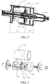
FIG. 1 according to an embodiment of the present invention; - FIG. 3
- is a structural cross-sectional view of the components in
FIG. 2 ; - FIG. 4
- is a structural exploded view of the components in
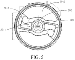
FIG. 2 ; and - FIG. 5
- is a top view of a deceleration apparatus in an axial direction.
- The present invention is described in detail below with reference with the embodiments shown in the accompanying drawings. However, these embodiments do not limit the present invention, and structural or functional transformations made by a person of ordinary skill in the art according to these embodiments are included in the protection scope of the present invention.
-
FIG. 1 illustrates a floor brush, including a housing and arolling brush 10, awind wheel assembly 20, and atransmission assembly 40 that are disposed in the housing. The basic working principle of the floor brush is that an air inlet is provided at the bottom of the housing. When the floor brush works, wind enters thewind wheel assembly 20 through the air inlet and drives blades of thewind wheel assembly 20 to rotate, thereby driving therolling brush 10 to rotate through thetransmission assembly 40. - Referring to
FIG. 1 to FIG. 4 , thewind wheel assembly 20 includes a rotatingshaft 202 and awind wheel body 201 disposed on the rotatingshaft 202. In an embodiment, thewind wheel body 201 further includes a left wind wheel and a right wind wheel, both of which may be disposed on the rotatingshaft 202 relative to each other. - The floor brush further includes a
deceleration apparatus 30. Thedeceleration apparatus 30 may be associated with thewind wheel assembly 20 to limit a rotation speed of thewind wheel assembly 20. - In an embodiment, the
deceleration apparatus 30 may include a movingportion 301 associated with the rotatingshaft 202 of thewind wheel assembly 20 and rotatable as thewind wheel assembly 20 rotates. - In an embodiment, the foregoing association manner may be that the
deceleration apparatus 30 and thewind wheel body 201 of thewind wheel assembly 20 are coaxially disposed, that is, disposed on the rotatingshaft 202. Therefore, thedeceleration apparatus 30 may be associated through thewind wheel assembly 20 and the rotating shaft. - In an embodiment, the
deceleration apparatus 30 may be disposed on at least one side of thewind wheel body 201. - The
deceleration apparatus 30 may be alternatively associated with thewind wheel assembly 20 through another connecting structure, so that the movingportion 301 is rotatable as thewind wheel assembly 20 rotates. - The
deceleration apparatus 30 further includes astationary portion 302 disposed on a radially outer portion of the movingportion 301 and spaced apart relative to the movingportion 301. The movingportion 301 has a brake portion 303 configured to come into contact with thestationary portion 302 and generating sliding friction under an action of a centrifugal force of rotation. A friction deceleration may be implemented through an interaction between thestationary portion 302 and the brake portion 303. - In an embodiment, the
stationary portion 302 may be disposed on an outer periphery of the movingportion 301 around the movingportion 301. For example, thestationary portion 302 may be a cylinder having an inner surface, or may be an annular body centered on therotating shaft 202, or may be an annular metal piece. By using annular components, when contact surfaces of the stationary portion and the moving portion come into contact with each other and generate sliding friction, the moving portion is uniformly forced, thereby accurately controlling the force that is applied by the deceleration apparatus to the wind wheel assembly, and further accurately controlling the speed of the wind wheel assembly driving the rolling brush. Thestationary portion 302 may be alternatively a plurality of components disposed around the outer periphery of the moving portion, and may not include a continuous circumference. - The
stationary portion 302 should be made of a wear-resistant and heat-resistant material, so that the service life of the stationary portion may be prolonged, and the performance stability of the stationary portion may be maintained during repeated friction between the stationary portion and the brake portion. In an embodiment, thedeceleration apparatus 30 may include a plurality of movingportions 301, and the plurality of movingportions 301 are evenly distributed around therotating shaft 202. For example, thedeceleration apparatus 30 includes two movingportions 301, and the two movingportions 301 may be symmetrically distributed around a centre of the rotating shaft, as shown inFIG. 5 . - Referring to
FIG. 5 , in an embodiment, the movingportion 301 may further include a fixedlimb 3011, afree end 3012 and a connectingportion 3013 connecting the fixed limb with the free end. The fixedlimb 3011 is fixedly connected to therotating shaft 202. When therotating shaft 202 rotates, thefree end 3012 is movable along a direction away from the centre of therotating shaft 202 and generates a displacement, to facilitate contact with thestationary portion 302. - In an embodiment, the
free end 3012 may move radially on a plane. The plane may be a plane perpendicular to therotating shaft 202 or a plane inclined by an angle relative to therotating shaft 202. - In an embodiment, when the
free end 3012 moves in a radial direction, the connectingportion 3013 and the fixedlimb 3011 may also has a displacement change to a certain degree. The displacement change is smaller than a displacement change of the movingportion 301, which is attributed to the material, quality, shape, and the like, of the connectingportion 3013 and the fixedlimb 3011. - In an embodiment, the fixed
limb 3011 and the connectingportion 3013 may be formed integrally; or the fixedlimb 3011, the connectingportion 3013 and thefree end 3012 may be formed integrally. The fixedlimb 3011, the connectingportion 3013 and thefree end 3012 may be made of a same material, for example, polyoxymethylene (POM) plastic. This type of material is of high strength and stiffness, good elasticity, and good wear reduction and resistance. - In an embodiment, the connecting
portion 3013 may have a reduced cross section, so that the connectingportion 3013 can be driven to deform during the displacement of thefree end 3012, making it easier for deformation to occur. - In particular, when the fixed
limb 3011, the connectingportion 3013, and thefree end 3012 are made of the same material and formed integrally, the connectingportion 3013 having the reduced cross section may move with the displacement of the free end, and the connecting portion drives the free end back to the original position after a centrifugal force at the free end is reduced or decreased. The durability of the connecting portion is also strengthened. - In an embodiment, the connecting
portion 3013 may be an elastic body. When subjected to the centrifugal force, thefree end 3012 simultaneously applies a force to the connectingportion 3013. The force includes at least the centrifugal force generated by rotation and a pulling force of thefree end 3012 applied to the connectingportion 3013. When the rotation speed of therotating shaft 202 decreases or when therotating shaft 202 stops rotating, the connectingportion 3013 may recover the deformation and make thefree end 3012 return to the original position. - In an embodiment, a brake portion 303 may be located on the
free end 3012. For example, the brake portion 303 may be disposed on a radially outer side of thefree end 3012. When moving, thefree end 3012 drives the brake portion 303 to move close to thestationary portion 302 to generate sliding friction. - The brake portion 303 may be disposed on an outer periphery of the
free end 3012. Alternatively, the brake portion 303 and thefree end 3012 may be a same component. In an embodiment, the brake portion 303 or thefree end 3012 may have an arc-shaped outer periphery. - In an embodiment, referring to
FIG. 5 , when two moving portions are evenly disposed in thedeceleration apparatus 30, fixedlimbs 3011, connectingportions 3013, andfree ends 3012 may be respectively symmetrically distributed around the centre of the rotating shaft. Thefree end 3012 may have an arc-shaped outer periphery that is parallel to the annularstationary portion 302. - Referring to
FIG. 3 and FIG. 4 , thewind wheel assembly 20 further includes awind wheel cover 203. Thewind wheel cover 203 may include afirst chamber 2031 and asecond chamber 2032. Thewind wheel body 201 and thedeceleration apparatus 30 are respectively disposed in thefirst chamber 2031 and thesecond chamber 2032. - In an embodiment, a
first blocking portion 501 is disposed between thefirst chamber 2031 and thesecond chamber 2032 to separate the two chambers. Thefirst blocking portion 501 and thewind wheel cover 203 may be formed integrally. In an embodiment, thefirst blocking portion 501 may be connected to therotating shaft 202. - In an embodiment, the
first blocking portion 501 and asecond blocking portion 502 may be disposed between thefirst chamber 2031 and thesecond chamber 2032. Thefirst blocking portion 501 is disposed on an inner wall of thewind wheel cover 203, and may be formed integrally with thewind wheel cover 203. Thesecond blocking portion 502 is disposed on therotating shaft 202, and an inner periphery edge of thefirst blocking portion 501 is closely attached to an outer periphery edge of thesecond blocking portion 502. - In an embodiment, the
stationary portion 302 is fixedly disposed on an inner wall of thesecond chamber 2032 where the stationary portion is located. - Widths of the
stationary portion 302 and thesecond chamber 2032 in an axial direction may be the same, so that thestationary portion 302 may be fixed through thefirst blocking portion 501 and a cover on the other side of thesecond chamber 2032. Thestationary portion 302 may be fixed on the wind wheel cover or the inner wall of thesecond chamber 2032 in another fixing manner. This is not limited here. An embodiment of the present invention further discloses a cleaning device having the foregoing floor brush. The cleaning device may be an upright cleaner, a hand-held vacuum cleaner, a canister vacuum cleaner, or a wet and dry vacuum cleaner. - The cleaning device can work by driving the rolling brush by using the wind wheel assembly.
- Based on the foregoing floor brush and the cleaning device having the floor brush, a specific working manner of the cleaning device are described below.
- Generally, when a specific amount of wind is drawn in through the air inlet at the bottom of the floor brush, the
wind wheel body 201 is subjected to a wind action and drives the rollingbrush 10 to rotate at a preset rotation speed. However, when the cleaning device cleans surfaces of different materials, an actual rotation speed of the rollingbrush 10 is lower than the preset rotation speed because the rollingbrush 10 is subjected to different degrees of friction. - When the cleaning device works on a floor, the
wind wheel assembly 20 drives the rollingbrush 10 to rotate. Generally, the rollingbrush 10 rotates at a first rolling brush rotation speed, for example, 5000 r/min. During the rotation, thedeceleration apparatus 30 rotates with the rotating shaft, and the movingportion 301 of thedeceleration apparatus 30 moves away from the centre of therotating shaft 202 under an action of a centrifugal force of rotation, comes into contact with thestationary portion 302, and performs circular movement against thestationary portion 301. In this process, the movingportion 301 is subjected to a frictional resistance and also hinders the rotation of therotating shaft 202, causing the rotation speed of the rollingbrush 10 to decrease to, for example, 1800 r/min. - When the cleaning device works on a carpet, similarly, the
wind wheel assembly 20 drives the rollingbrush 10 to rotate. Generally, the rollingbrush 10 rotates at a second rolling brush rotation speed, for example, 2000 r/min. During the rotation, thedeceleration apparatus 30 rotates with therotating shaft 202, and the movingportion 301 of thedeceleration apparatus 30 moves away from the centre of the rotating shaft under an action of a centrifugal force of rotation, comes into contact with thestationary portion 302, and performs circular movement against thestationary portion 302. In this process, the movingportion 301 is subjected to a frictional resistance and also hinders the rotation of therotating shaft 202, causing the rotation speed of the rollingbrush 10 to decrease to, for example, 1800 r/min. - The foregoing descriptions are merely specific implementations of the present invention, but are not intended to limit the protection scope of the present invention. Any modification or replacement readily figured out by a person skilled in the art within the technical scope disclosed in the present invention shall fall within the protection scope of the present invention. Therefore, the protection scope of the present invention shall be subject to the protection scope of the claims.
-
- 10
- rolling brush
- 20
- wind wheel assembly
- 30
- deceleration apparatus
- 40
- transmission assembly
- 201
- wind wheel body
- 202
- rotating shaft
- 203
- wind wheel cover
- 301
- moving portion
- 302
- stationary portion
- 303
- brake portion
- 501
- first blocking portion
- 502
- second blocking portion
- 2031
- first chamber
- 2032
- second chamber
- 3011
- fixed limb
- 3012
- free end
- 3013
- connecting portion
Claims (15)
- A floor brush, comprising a housing and a rolling brush (10) and a wind wheel assembly (20) disposed in the housing, the wind wheel assembly (20) being connected to the rolling brush (10) through a transmission assembly (40), and the wind wheel assembly (20) comprising a rotating shaft (202) and a wind wheel body (201) disposed on the rotating shaft (202), characterized in that a deceleration apparatus (30) is associated with the wind wheel assembly (20) to limit a rotation speed of the wind wheel assembly (20), and the deceleration apparatus (30) comprises a moving portion (301) associated with the rotating shaft (202) of the wind wheel assembly (20) and rotatable as the wind wheel assembly (20) rotates and a stationary portion (302) disposed on a radially outer portion of the moving portion (301) and spaced apart relative to the moving portion (301), the moving portion (301) having a brake portion (303) configured to come into contact with the stationary portion (302) and generating sliding friction under an action of a centrifugal force of rotation.
- The floor brush according to claim 1, characterized in that the stationary portion (302) is disposed on an outer periphery of the moving portion (301) around the moving portion (301).
- The floor brush according to claim 1 or 2, characterized in that the moving portion (301) further comprises a fixed limb (3011), a free end (3012), and a connecting portion (3013) connecting the fixed limb with the free end, wherein the fixed limb (3011) is fixedly connected to the rotating shaft (202), when the rotating shaft (202) rotates, the free end (3012) is movable along a direction away from a centre of the rotating shaft, and the brake portion (303) is located on the free end (3012).
- The floor brush according to claim 3, characterized in that the fixed limb (3011) and the connecting portion (3013) are formed integrally; or the fixed limb (3011), the connecting portion (3013), and the free end (3012) are formed integrally.
- The floor brush according to claim 4, characterized in that the fixed limb (3011), the connecting portion (3013), and the free end (3012) are made of POM plastic.
- The floor brush according to claim 4, characterized in that the connecting portion (3013) has a reduced cross section.
- The floor brush according to claim 1, characterized in that the deceleration apparatus (30) comprises at least two moving portions (301), the two moving portions (301) being evenly distributed around the rotating shaft (202).
- The floor brush according to claim 1, characterized in that the wind wheel assembly (20) further comprises a wind wheel cover (203), the wind wheel cover (203) comprising a first chamber (2031) and a second chamber (2032), wherein the wind wheel body (201) and the deceleration apparatus (30) are respectively disposed in the first chamber (2031) and the second chamber (2032).
- The floor brush according to claim 8, characterized in that the stationary portion (302) is fixedly disposed on an inner wall of the second chamber (2032) where the stationary portion is located.
- The floor brush according to claim 8, characterized in that a first blocking portion (501) is disposed between the first chamber (2031) and the second chamber (2032) to separate the two chambers.
- The floor brush according to claim 10, characterized by further comprising a second blocking portion (502), wherein the first blocking portion (501) is disposed on an inner wall of the wind wheel cover (203), the second blocking portion (502) is disposed on the rotating shaft (202), and an inner periphery edge of the first blocking portion (501) is closely attached to an outer periphery edge of the second blocking portion (502).
- The floor brush according to claim 1 or 2, characterized in that the stationary portion (302) is an annular metal piece.
- The floor brush according to claim 1, characterized in that the free end (3012) or the brake portion (303) has an arc-shaped outer periphery.
- The floor brush according to claim 1, characterized in that the wind wheel body (201) and the deceleration apparatus (30) are coaxially disposed.
- A cleaning device comprising the floor brush according to any one of claims 1 to 14.
Applications Claiming Priority (1)
| Application Number | Priority Date | Filing Date | Title |
|---|---|---|---|
| CN202010329966.5A CN113545697A (en) | 2020-04-24 | 2020-04-24 | Scrubbing brush and cleaning device |
Publications (2)
| Publication Number | Publication Date |
|---|---|
| EP3900593A1 true EP3900593A1 (en) | 2021-10-27 |
| EP3900593B1 EP3900593B1 (en) | 2023-12-13 |
Family
ID=75562558
Family Applications (1)
| Application Number | Title | Priority Date | Filing Date |
|---|---|---|---|
| EP21168750.4A Active EP3900593B1 (en) | 2020-04-24 | 2021-04-16 | Floor brush and cleaning device |
Country Status (2)
| Country | Link |
|---|---|
| EP (1) | EP3900593B1 (en) |
| CN (1) | CN113545697A (en) |
Families Citing this family (1)
| Publication number | Priority date | Publication date | Assignee | Title |
|---|---|---|---|---|
| CN217959994U (en) * | 2022-05-20 | 2022-12-06 | 追觅创新科技(苏州)有限公司 | Rolling brush self-locking structure, floor brush and cleaning equipment |
Citations (2)
| Publication number | Priority date | Publication date | Assignee | Title |
|---|---|---|---|---|
| DE19507528A1 (en) * | 1995-03-03 | 1996-09-05 | Wessel Werk Gmbh | Noise reduction method for suction air-driven turbines in vacuum cleaner cleaning heads |
| DE60310578T2 (en) * | 2002-09-24 | 2007-10-04 | Dyson Technology Ltd., Malmesbury | A vacuum cleaning |
Family Cites Families (3)
| Publication number | Priority date | Publication date | Assignee | Title |
|---|---|---|---|---|
| CN109538420B (en) * | 2018-10-17 | 2020-03-31 | 河北建投新能源有限公司 | High-stability wind power generation equipment and method thereof |
| CN210077550U (en) * | 2019-04-02 | 2020-02-18 | 苏州君之宏电器科技有限公司 | Electric floor brush |
| DE202019102533U1 (en) * | 2019-05-06 | 2019-05-14 | Einhell Germany Ag | Electric cleaning device for motor assisted cleaning of surfaces |
-
2020
- 2020-04-24 CN CN202010329966.5A patent/CN113545697A/en not_active Withdrawn
-
2021
- 2021-04-16 EP EP21168750.4A patent/EP3900593B1/en active Active
Patent Citations (2)
| Publication number | Priority date | Publication date | Assignee | Title |
|---|---|---|---|---|
| DE19507528A1 (en) * | 1995-03-03 | 1996-09-05 | Wessel Werk Gmbh | Noise reduction method for suction air-driven turbines in vacuum cleaner cleaning heads |
| DE60310578T2 (en) * | 2002-09-24 | 2007-10-04 | Dyson Technology Ltd., Malmesbury | A vacuum cleaning |
Also Published As
| Publication number | Publication date |
|---|---|
| CN113545697A (en) | 2021-10-26 |
| EP3900593B1 (en) | 2023-12-13 |
Similar Documents
| Publication | Publication Date | Title |
|---|---|---|
| US11633764B2 (en) | Cleaning apparatus with anti-hair wrap management systems | |
| EP0659522A1 (en) | Random orbit sander having braking member | |
| JP2017023708A (en) | Cleaner comprising rotatable cleaning roller | |
| CN111496598B (en) | Plane grinding device and plane grinding robot | |
| EP3900593B1 (en) | Floor brush and cleaning device | |
| CN108852168B (en) | Floor brush assembly and dust collector comprising same | |
| CA2061493A1 (en) | Vacuum cleaning tool | |
| KR20010032887A (en) | A clutch mechanism | |
| US5611109A (en) | Cleaning roller for the suction head of a vacuum cleaning device | |
| CN1165407C (en) | Eccentric disc grinder with housing | |
| JP6409754B2 (en) | fan | |
| US4028953A (en) | Variable diameter pulley | |
| CN211324790U (en) | Round brush subassembly and cleaning machines people | |
| CN112675942A (en) | Rice huller and from locking-type rubber roll variable speed structure thereof | |
| JP6568543B2 (en) | Axial transmission system | |
| CN113768407A (en) | Cutting device, cleaning equipment, cleaning base station, cleaning system and method | |
| JP2013152017A (en) | Cleaner motor bearing | |
| EP0753677A1 (en) | A seal for mechanical members coupled for relative rotation, provided with at least one variable-attitude lip | |
| US4785620A (en) | Bearing and drive for a spinning rotor | |
| CN110697026A (en) | Power device and aircraft | |
| CN213282739U (en) | Roller assemblies for mobile cleaning systems | |
| CN206617536U (en) | The frictional one-way belt sheave of roller | |
| CN213282740U (en) | Roller assemblies for mobile cleaning systems | |
| CN114508545B (en) | Bearing | |
| CN216535187U (en) | Wheel and cleaning equipment applying same |
Legal Events
| Date | Code | Title | Description |
|---|---|---|---|
| PUAI | Public reference made under article 153(3) epc to a published international application that has entered the european phase |
Free format text: ORIGINAL CODE: 0009012 |
|
| STAA | Information on the status of an ep patent application or granted ep patent |
Free format text: STATUS: THE APPLICATION HAS BEEN PUBLISHED |
|
| AK | Designated contracting states |
Kind code of ref document: A1 Designated state(s): AL AT BE BG CH CY CZ DE DK EE ES FI FR GB GR HR HU IE IS IT LI LT LU LV MC MK MT NL NO PL PT RO RS SE SI SK SM TR |
|
| B565 | Issuance of search results under rule 164(2) epc |
Effective date: 20210924 |
|
| STAA | Information on the status of an ep patent application or granted ep patent |
Free format text: STATUS: REQUEST FOR EXAMINATION WAS MADE |
|
| 17P | Request for examination filed |
Effective date: 20220428 |
|
| RBV | Designated contracting states (corrected) |
Designated state(s): AL AT BE BG CH CY CZ DE DK EE ES FI FR GB GR HR HU IE IS IT LI LT LU LV MC MK MT NL NO PL PT RO RS SE SI SK SM TR |
|
| GRAP | Despatch of communication of intention to grant a patent |
Free format text: ORIGINAL CODE: EPIDOSNIGR1 |
|
| STAA | Information on the status of an ep patent application or granted ep patent |
Free format text: STATUS: GRANT OF PATENT IS INTENDED |
|
| INTG | Intention to grant announced |
Effective date: 20230725 |
|
| GRAS | Grant fee paid |
Free format text: ORIGINAL CODE: EPIDOSNIGR3 |
|
| GRAA | (expected) grant |
Free format text: ORIGINAL CODE: 0009210 |
|
| STAA | Information on the status of an ep patent application or granted ep patent |
Free format text: STATUS: THE PATENT HAS BEEN GRANTED |
|
| AK | Designated contracting states |
Kind code of ref document: B1 Designated state(s): AL AT BE BG CH CY CZ DE DK EE ES FI FR GB GR HR HU IE IS IT LI LT LU LV MC MK MT NL NO PL PT RO RS SE SI SK SM TR |
|
| REG | Reference to a national code |
Ref country code: GB Ref legal event code: FG4D |
|
| REG | Reference to a national code |
Ref country code: CH Ref legal event code: EP |
|
| REG | Reference to a national code |
Ref country code: DE Ref legal event code: R096 Ref document number: 602021007589 Country of ref document: DE |
|
| REG | Reference to a national code |
Ref country code: IE Ref legal event code: FG4D |
|
| PG25 | Lapsed in a contracting state [announced via postgrant information from national office to epo] |
Ref country code: GR Free format text: LAPSE BECAUSE OF FAILURE TO SUBMIT A TRANSLATION OF THE DESCRIPTION OR TO PAY THE FEE WITHIN THE PRESCRIBED TIME-LIMIT Effective date: 20240314 |
|
| REG | Reference to a national code |
Ref country code: LT Ref legal event code: MG9D |
|
| PG25 | Lapsed in a contracting state [announced via postgrant information from national office to epo] |
Ref country code: LT Free format text: LAPSE BECAUSE OF FAILURE TO SUBMIT A TRANSLATION OF THE DESCRIPTION OR TO PAY THE FEE WITHIN THE PRESCRIBED TIME-LIMIT Effective date: 20231213 |
|
| REG | Reference to a national code |
Ref country code: NL Ref legal event code: MP Effective date: 20231213 |
|
| PG25 | Lapsed in a contracting state [announced via postgrant information from national office to epo] |
Ref country code: ES Free format text: LAPSE BECAUSE OF FAILURE TO SUBMIT A TRANSLATION OF THE DESCRIPTION OR TO PAY THE FEE WITHIN THE PRESCRIBED TIME-LIMIT Effective date: 20231213 |
|
| PG25 | Lapsed in a contracting state [announced via postgrant information from national office to epo] |
Ref country code: LT Free format text: LAPSE BECAUSE OF FAILURE TO SUBMIT A TRANSLATION OF THE DESCRIPTION OR TO PAY THE FEE WITHIN THE PRESCRIBED TIME-LIMIT Effective date: 20231213 Ref country code: GR Free format text: LAPSE BECAUSE OF FAILURE TO SUBMIT A TRANSLATION OF THE DESCRIPTION OR TO PAY THE FEE WITHIN THE PRESCRIBED TIME-LIMIT Effective date: 20240314 Ref country code: ES Free format text: LAPSE BECAUSE OF FAILURE TO SUBMIT A TRANSLATION OF THE DESCRIPTION OR TO PAY THE FEE WITHIN THE PRESCRIBED TIME-LIMIT Effective date: 20231213 Ref country code: BG Free format text: LAPSE BECAUSE OF FAILURE TO SUBMIT A TRANSLATION OF THE DESCRIPTION OR TO PAY THE FEE WITHIN THE PRESCRIBED TIME-LIMIT Effective date: 20240313 |
|
| REG | Reference to a national code |
Ref country code: AT Ref legal event code: MK05 Ref document number: 1639705 Country of ref document: AT Kind code of ref document: T Effective date: 20231213 |
|
| PG25 | Lapsed in a contracting state [announced via postgrant information from national office to epo] |
Ref country code: NL Free format text: LAPSE BECAUSE OF FAILURE TO SUBMIT A TRANSLATION OF THE DESCRIPTION OR TO PAY THE FEE WITHIN THE PRESCRIBED TIME-LIMIT Effective date: 20231213 |
|
| PG25 | Lapsed in a contracting state [announced via postgrant information from national office to epo] |
Ref country code: SE Free format text: LAPSE BECAUSE OF FAILURE TO SUBMIT A TRANSLATION OF THE DESCRIPTION OR TO PAY THE FEE WITHIN THE PRESCRIBED TIME-LIMIT Effective date: 20231213 Ref country code: RS Free format text: LAPSE BECAUSE OF FAILURE TO SUBMIT A TRANSLATION OF THE DESCRIPTION OR TO PAY THE FEE WITHIN THE PRESCRIBED TIME-LIMIT Effective date: 20231213 Ref country code: NO Free format text: LAPSE BECAUSE OF FAILURE TO SUBMIT A TRANSLATION OF THE DESCRIPTION OR TO PAY THE FEE WITHIN THE PRESCRIBED TIME-LIMIT Effective date: 20240313 Ref country code: NL Free format text: LAPSE BECAUSE OF FAILURE TO SUBMIT A TRANSLATION OF THE DESCRIPTION OR TO PAY THE FEE WITHIN THE PRESCRIBED TIME-LIMIT Effective date: 20231213 Ref country code: LV Free format text: LAPSE BECAUSE OF FAILURE TO SUBMIT A TRANSLATION OF THE DESCRIPTION OR TO PAY THE FEE WITHIN THE PRESCRIBED TIME-LIMIT Effective date: 20231213 Ref country code: HR Free format text: LAPSE BECAUSE OF FAILURE TO SUBMIT A TRANSLATION OF THE DESCRIPTION OR TO PAY THE FEE WITHIN THE PRESCRIBED TIME-LIMIT Effective date: 20231213 |
|
| PG25 | Lapsed in a contracting state [announced via postgrant information from national office to epo] |
Ref country code: IS Free format text: LAPSE BECAUSE OF FAILURE TO SUBMIT A TRANSLATION OF THE DESCRIPTION OR TO PAY THE FEE WITHIN THE PRESCRIBED TIME-LIMIT Effective date: 20240413 |
|
| PG25 | Lapsed in a contracting state [announced via postgrant information from national office to epo] |
Ref country code: CZ Free format text: LAPSE BECAUSE OF FAILURE TO SUBMIT A TRANSLATION OF THE DESCRIPTION OR TO PAY THE FEE WITHIN THE PRESCRIBED TIME-LIMIT Effective date: 20231213 Ref country code: AT Free format text: LAPSE BECAUSE OF FAILURE TO SUBMIT A TRANSLATION OF THE DESCRIPTION OR TO PAY THE FEE WITHIN THE PRESCRIBED TIME-LIMIT Effective date: 20231213 |
|
| PG25 | Lapsed in a contracting state [announced via postgrant information from national office to epo] |
Ref country code: SK Free format text: LAPSE BECAUSE OF FAILURE TO SUBMIT A TRANSLATION OF THE DESCRIPTION OR TO PAY THE FEE WITHIN THE PRESCRIBED TIME-LIMIT Effective date: 20231213 |
|
| PG25 | Lapsed in a contracting state [announced via postgrant information from national office to epo] |
Ref country code: SM Free format text: LAPSE BECAUSE OF FAILURE TO SUBMIT A TRANSLATION OF THE DESCRIPTION OR TO PAY THE FEE WITHIN THE PRESCRIBED TIME-LIMIT Effective date: 20231213 Ref country code: SK Free format text: LAPSE BECAUSE OF FAILURE TO SUBMIT A TRANSLATION OF THE DESCRIPTION OR TO PAY THE FEE WITHIN THE PRESCRIBED TIME-LIMIT Effective date: 20231213 Ref country code: RO Free format text: LAPSE BECAUSE OF FAILURE TO SUBMIT A TRANSLATION OF THE DESCRIPTION OR TO PAY THE FEE WITHIN THE PRESCRIBED TIME-LIMIT Effective date: 20231213 Ref country code: IT Free format text: LAPSE BECAUSE OF FAILURE TO SUBMIT A TRANSLATION OF THE DESCRIPTION OR TO PAY THE FEE WITHIN THE PRESCRIBED TIME-LIMIT Effective date: 20231213 Ref country code: IS Free format text: LAPSE BECAUSE OF FAILURE TO SUBMIT A TRANSLATION OF THE DESCRIPTION OR TO PAY THE FEE WITHIN THE PRESCRIBED TIME-LIMIT Effective date: 20240413 Ref country code: EE Free format text: LAPSE BECAUSE OF FAILURE TO SUBMIT A TRANSLATION OF THE DESCRIPTION OR TO PAY THE FEE WITHIN THE PRESCRIBED TIME-LIMIT Effective date: 20231213 Ref country code: CZ Free format text: LAPSE BECAUSE OF FAILURE TO SUBMIT A TRANSLATION OF THE DESCRIPTION OR TO PAY THE FEE WITHIN THE PRESCRIBED TIME-LIMIT Effective date: 20231213 Ref country code: AT Free format text: LAPSE BECAUSE OF FAILURE TO SUBMIT A TRANSLATION OF THE DESCRIPTION OR TO PAY THE FEE WITHIN THE PRESCRIBED TIME-LIMIT Effective date: 20231213 |
|
| PG25 | Lapsed in a contracting state [announced via postgrant information from national office to epo] |
Ref country code: PT Free format text: LAPSE BECAUSE OF FAILURE TO SUBMIT A TRANSLATION OF THE DESCRIPTION OR TO PAY THE FEE WITHIN THE PRESCRIBED TIME-LIMIT Effective date: 20240415 Ref country code: PL Free format text: LAPSE BECAUSE OF FAILURE TO SUBMIT A TRANSLATION OF THE DESCRIPTION OR TO PAY THE FEE WITHIN THE PRESCRIBED TIME-LIMIT Effective date: 20231213 |
|
| PG25 | Lapsed in a contracting state [announced via postgrant information from national office to epo] |
Ref country code: PT Free format text: LAPSE BECAUSE OF FAILURE TO SUBMIT A TRANSLATION OF THE DESCRIPTION OR TO PAY THE FEE WITHIN THE PRESCRIBED TIME-LIMIT Effective date: 20240415 Ref country code: PL Free format text: LAPSE BECAUSE OF FAILURE TO SUBMIT A TRANSLATION OF THE DESCRIPTION OR TO PAY THE FEE WITHIN THE PRESCRIBED TIME-LIMIT Effective date: 20231213 |
|
| REG | Reference to a national code |
Ref country code: DE Ref legal event code: R097 Ref document number: 602021007589 Country of ref document: DE |
|
| PG25 | Lapsed in a contracting state [announced via postgrant information from national office to epo] |
Ref country code: DK Free format text: LAPSE BECAUSE OF FAILURE TO SUBMIT A TRANSLATION OF THE DESCRIPTION OR TO PAY THE FEE WITHIN THE PRESCRIBED TIME-LIMIT Effective date: 20231213 |
|
| PLBE | No opposition filed within time limit |
Free format text: ORIGINAL CODE: 0009261 |
|
| STAA | Information on the status of an ep patent application or granted ep patent |
Free format text: STATUS: NO OPPOSITION FILED WITHIN TIME LIMIT |
|
| PG25 | Lapsed in a contracting state [announced via postgrant information from national office to epo] |
Ref country code: SI Free format text: LAPSE BECAUSE OF FAILURE TO SUBMIT A TRANSLATION OF THE DESCRIPTION OR TO PAY THE FEE WITHIN THE PRESCRIBED TIME-LIMIT Effective date: 20231213 |
|
| PG25 | Lapsed in a contracting state [announced via postgrant information from national office to epo] |
Ref country code: SI Free format text: LAPSE BECAUSE OF FAILURE TO SUBMIT A TRANSLATION OF THE DESCRIPTION OR TO PAY THE FEE WITHIN THE PRESCRIBED TIME-LIMIT Effective date: 20231213 Ref country code: DK Free format text: LAPSE BECAUSE OF FAILURE TO SUBMIT A TRANSLATION OF THE DESCRIPTION OR TO PAY THE FEE WITHIN THE PRESCRIBED TIME-LIMIT Effective date: 20231213 |
|
| 26N | No opposition filed |
Effective date: 20240916 |
|
| PG25 | Lapsed in a contracting state [announced via postgrant information from national office to epo] |
Ref country code: MC Free format text: LAPSE BECAUSE OF FAILURE TO SUBMIT A TRANSLATION OF THE DESCRIPTION OR TO PAY THE FEE WITHIN THE PRESCRIBED TIME-LIMIT Effective date: 20231213 |
|
| PG25 | Lapsed in a contracting state [announced via postgrant information from national office to epo] |
Ref country code: MC Free format text: LAPSE BECAUSE OF FAILURE TO SUBMIT A TRANSLATION OF THE DESCRIPTION OR TO PAY THE FEE WITHIN THE PRESCRIBED TIME-LIMIT Effective date: 20231213 |
|
| REG | Reference to a national code |
Ref country code: CH Ref legal event code: PL |
|
| PG25 | Lapsed in a contracting state [announced via postgrant information from national office to epo] |
Ref country code: LU Free format text: LAPSE BECAUSE OF NON-PAYMENT OF DUE FEES Effective date: 20240416 |
|
| REG | Reference to a national code |
Ref country code: BE Ref legal event code: MM Effective date: 20240430 |
|
| PG25 | Lapsed in a contracting state [announced via postgrant information from national office to epo] |
Ref country code: LU Free format text: LAPSE BECAUSE OF NON-PAYMENT OF DUE FEES Effective date: 20240416 |
|
| PG25 | Lapsed in a contracting state [announced via postgrant information from national office to epo] |
Ref country code: BE Free format text: LAPSE BECAUSE OF NON-PAYMENT OF DUE FEES Effective date: 20240430 |
|
| PG25 | Lapsed in a contracting state [announced via postgrant information from national office to epo] |
Ref country code: BE Free format text: LAPSE BECAUSE OF NON-PAYMENT OF DUE FEES Effective date: 20240430 Ref country code: CH Free format text: LAPSE BECAUSE OF NON-PAYMENT OF DUE FEES Effective date: 20240430 |
|
| PG25 | Lapsed in a contracting state [announced via postgrant information from national office to epo] |
Ref country code: IE Free format text: LAPSE BECAUSE OF NON-PAYMENT OF DUE FEES Effective date: 20240416 |
|
| PGFP | Annual fee paid to national office [announced via postgrant information from national office to epo] |
Ref country code: DE Payment date: 20250430 Year of fee payment: 5 |
|
| PGFP | Annual fee paid to national office [announced via postgrant information from national office to epo] |
Ref country code: FR Payment date: 20250428 Year of fee payment: 5 |
|
| PG25 | Lapsed in a contracting state [announced via postgrant information from national office to epo] |
Ref country code: CY Free format text: LAPSE BECAUSE OF FAILURE TO SUBMIT A TRANSLATION OF THE DESCRIPTION OR TO PAY THE FEE WITHIN THE PRESCRIBED TIME-LIMIT; INVALID AB INITIO Effective date: 20210416 |
|
| PG25 | Lapsed in a contracting state [announced via postgrant information from national office to epo] |
Ref country code: HU Free format text: LAPSE BECAUSE OF FAILURE TO SUBMIT A TRANSLATION OF THE DESCRIPTION OR TO PAY THE FEE WITHIN THE PRESCRIBED TIME-LIMIT; INVALID AB INITIO Effective date: 20210416 |
|
| PG25 | Lapsed in a contracting state [announced via postgrant information from national office to epo] |
Ref country code: FI Free format text: LAPSE BECAUSE OF FAILURE TO SUBMIT A TRANSLATION OF THE DESCRIPTION OR TO PAY THE FEE WITHIN THE PRESCRIBED TIME-LIMIT Effective date: 20231213 |
|
| PGFP | Annual fee paid to national office [announced via postgrant information from national office to epo] |
Ref country code: GB Payment date: 20260324 Year of fee payment: 6 |