EP3900509B1 - Field operation vehicle - Google Patents
Field operation vehicle Download PDFInfo
- Publication number
- EP3900509B1 EP3900509B1 EP19899894.0A EP19899894A EP3900509B1 EP 3900509 B1 EP3900509 B1 EP 3900509B1 EP 19899894 A EP19899894 A EP 19899894A EP 3900509 B1 EP3900509 B1 EP 3900509B1
- Authority
- EP
- European Patent Office
- Prior art keywords
- travel
- agricultural field
- travel path
- vehicle body
- vehicle
- Prior art date
- Legal status (The legal status is an assumption and is not a legal conclusion. Google has not performed a legal analysis and makes no representation as to the accuracy of the status listed.)
- Active
Links
Images





Classifications
-
- A—HUMAN NECESSITIES
- A01—AGRICULTURE; FORESTRY; ANIMAL HUSBANDRY; HUNTING; TRAPPING; FISHING
- A01B—SOIL WORKING IN AGRICULTURE OR FORESTRY; PARTS, DETAILS, OR ACCESSORIES OF AGRICULTURAL MACHINES OR IMPLEMENTS, IN GENERAL
- A01B69/00—Steering of agricultural machines or implements; Guiding agricultural machines or implements on a desired track
- A01B69/007—Steering or guiding of agricultural vehicles, e.g. steering of the tractor to keep the plough in the furrow
- A01B69/008—Steering or guiding of agricultural vehicles, e.g. steering of the tractor to keep the plough in the furrow automatic
-
- B—PERFORMING OPERATIONS; TRANSPORTING
- B60—VEHICLES IN GENERAL
- B60Q—ARRANGEMENT OF SIGNALLING OR LIGHTING DEVICES, THE MOUNTING OR SUPPORTING THEREOF OR CIRCUITS THEREFOR, FOR VEHICLES IN GENERAL
- B60Q9/00—Arrangement or adaptation of signal devices not provided for in one of main groups B60Q1/00 - B60Q7/00, e.g. haptic signalling
-
- B—PERFORMING OPERATIONS; TRANSPORTING
- B60—VEHICLES IN GENERAL
- B60W—CONJOINT CONTROL OF VEHICLE SUB-UNITS OF DIFFERENT TYPE OR DIFFERENT FUNCTION; CONTROL SYSTEMS SPECIALLY ADAPTED FOR HYBRID VEHICLES; ROAD VEHICLE DRIVE CONTROL SYSTEMS FOR PURPOSES NOT RELATED TO THE CONTROL OF A PARTICULAR SUB-UNIT
- B60W60/00—Drive control systems specially adapted for autonomous road vehicles
- B60W60/001—Planning or execution of driving tasks
- B60W60/0025—Planning or execution of driving tasks specially adapted for specific operations
- B60W60/00256—Delivery operations
-
- B—PERFORMING OPERATIONS; TRANSPORTING
- B60—VEHICLES IN GENERAL
- B60W—CONJOINT CONTROL OF VEHICLE SUB-UNITS OF DIFFERENT TYPE OR DIFFERENT FUNCTION; CONTROL SYSTEMS SPECIALLY ADAPTED FOR HYBRID VEHICLES; ROAD VEHICLE DRIVE CONTROL SYSTEMS FOR PURPOSES NOT RELATED TO THE CONTROL OF A PARTICULAR SUB-UNIT
- B60W60/00—Drive control systems specially adapted for autonomous road vehicles
- B60W60/005—Handover processes
- B60W60/0051—Handover processes from occupants to vehicle
-
- G—PHYSICS
- G05—CONTROLLING; REGULATING
- G05D—SYSTEMS FOR CONTROLLING OR REGULATING NON-ELECTRIC VARIABLES
- G05D1/00—Control of position, course, altitude or attitude of land, water, air or space vehicles, e.g. using automatic pilots
- G05D1/0088—Control of position, course, altitude or attitude of land, water, air or space vehicles, e.g. using automatic pilots characterized by the autonomous decision making process, e.g. artificial intelligence, predefined behaviours
-
- G—PHYSICS
- G05—CONTROLLING; REGULATING
- G05D—SYSTEMS FOR CONTROLLING OR REGULATING NON-ELECTRIC VARIABLES
- G05D1/00—Control of position, course, altitude or attitude of land, water, air or space vehicles, e.g. using automatic pilots
- G05D1/02—Control of position or course in two dimensions
- G05D1/021—Control of position or course in two dimensions specially adapted to land vehicles
- G05D1/0212—Control of position or course in two dimensions specially adapted to land vehicles with means for defining a desired trajectory
-
- G—PHYSICS
- G05—CONTROLLING; REGULATING
- G05D—SYSTEMS FOR CONTROLLING OR REGULATING NON-ELECTRIC VARIABLES
- G05D1/00—Control of position, course, altitude or attitude of land, water, air or space vehicles, e.g. using automatic pilots
- G05D1/02—Control of position or course in two dimensions
- G05D1/021—Control of position or course in two dimensions specially adapted to land vehicles
- G05D1/0212—Control of position or course in two dimensions specially adapted to land vehicles with means for defining a desired trajectory
- G05D1/0219—Control of position or course in two dimensions specially adapted to land vehicles with means for defining a desired trajectory ensuring the processing of the whole working surface
-
- B—PERFORMING OPERATIONS; TRANSPORTING
- B60—VEHICLES IN GENERAL
- B60W—CONJOINT CONTROL OF VEHICLE SUB-UNITS OF DIFFERENT TYPE OR DIFFERENT FUNCTION; CONTROL SYSTEMS SPECIALLY ADAPTED FOR HYBRID VEHICLES; ROAD VEHICLE DRIVE CONTROL SYSTEMS FOR PURPOSES NOT RELATED TO THE CONTROL OF A PARTICULAR SUB-UNIT
- B60W2300/00—Indexing codes relating to the type of vehicle
- B60W2300/15—Agricultural vehicles
Definitions
- the present invention relates to an agricultural field work vehicle capable of traveling autonomously along a target travel path.
- An agricultural field work vehicle configured to travel autonomously along a target travel path suspends work for any of various reasons and moves off the target travel path.
- An agricultural field work vehicle is required to move off a target travel path while performing work for lack of fuel or due to a limit on the work capacity (such as a limit on the harvest capacity or addition of an agent to be supplied to the agricultural field).
- the agricultural field work vehicle moves to a particular place to overcome a circumstance that required the agricultural field work vehicle to move off the target travel path, and then returns to the position at which the agricultural field work vehicle moved off the target travel path. At that position, the agricultural field work vehicle resumes performing work during autonomous travel.
- Japanese unexamined patent application publication, Tokukai, No. 2018-116613 discloses a work vehicle configured to, when the work vehicle suspends work travel, record suspension information on the work travel suspended.
- a monitor displays the position at which the work vehicle suspended the work travel (which position is recorded in the suspension information) as a work resumption position together with a travel path set for the agricultural field.
- the work resumption position which is indicated in resumption information, is either a point at which the work vehicle suspended the previous work travel or an end of a linear portion of the travel path extending through the point.
- Document US 2018/206391 A1 describes a travel control apparatus for a work vehicle including a display and a circuitry.
- the display is to display a position of the work vehicle.
- the circuitry is configured to display in the display a guide index via which the work vehicle is manually guided to an automatic-travel permitted area in which the work vehicle is configured to automatically travel, and to determine whether the work vehicle is located in the automatic-travel permitted area.
- Document US 2017/177002 A1 describes an autonomous travel work vehicle, which is provided with a position calculation means that measures the device body position by means of a satellite positioning system, a steering actuator that operates a steering device, an engine rotation control means, a transmission means, and a control device that controls each of same, is caused to autonomously travel, along a set travel path stored in the control device, by an accompanying travel work vehicle that works while accompanying the travel of the autonomous travel work vehicle by means of attended operation and that is mounted with a remote operation device that can operate the autonomous travel work vehicle, and the control device halts autonomous travel when a signal disruption from the satellites, a large deviation from the set travel path, an abnormal sensor value, fuel exhaustion, or the like is detected.
- Document JP 2018/073399 A1 describes a travel route generation device for generating a travel route for a work vehicle that travels while working in a work site, comprising a route management section that calculates a travel route element group which is the aggregate of many travel route elements composing the travel route covering a work object area of the work site and that stores the travel route element group such that the element group is readable.
- This travel route element group is a line group formed from mesh-division lines for mesh-dividing the work object area.
- the work vehicle disclosed in JP 2018-116613 is, when resuming work travel after suspending it and moving off a travel path, manually driven to a work resumption position displayed on the monitor, and the work vehicle starts autonomous travel at the work resumption position.
- the work vehicle will, however, not start autonomous travel even when it has come to a position near the work resumption position if the control system of the work vehicle fails at that position to detect the travel path as a target for autonomous travel. Further, even if the control system has detected the target travel path, and the work vehicle is to resume autonomous travel, the work vehicle may, depending on the positional relationship between the travel path and the work vehicle, be steered by a large amount when resuming autonomous travel and damage the agricultural field.
- an object of the present invention to provide an agricultural field work vehicle capable of, after suspending agricultural field work during autonomous travel and moving off a target travel path, resuming autonomous travel smoothly at a desired work resumption position.
- the agricultural field work vehicle if the agricultural field work vehicle has moved off a target travel path for refueling or rest of the driver, the agricultural field work vehicle records either or both of the move-off position and the move-off travel path as move-off information.
- the agricultural field work vehicle selects, on the basis of the move-off information, an initial target travel path (resumption travel path) on which the agricultural field work vehicle will resume traveling autonomously.
- the determining section determines whether the agricultural field work vehicle is able to transition smoothly from manual travel to autonomous travel.
- the determining section determines, for instance, whether the autonomous travel control system has located the resumption travel path and/or whether the agricultural field work vehicle will be able to travel autonomously along the resumption travel path without a steering operation so large as to damage the agricultural field. Thus, if the determining section has determined that the agricultural field work vehicle will be able to travel autonomously, the agricultural field work vehicle will transition smoothly from manual travel to autonomous travel.
- a further embodiment of the present invention further includes: a manual operation tool configured to start autonomous travel by the vehicle body, wherein after the determining section has determined that the agricultural field work vehicle is able to perform the transition, the manual operation tool is operated to cause the autonomous travel control section to start the autonomous travel by the vehicle body.
- This embodiment is arranged to transition from manual travel to autonomous travel under a transition condition of whether the determining section has determined that the agricultural field work vehicle is able to transition to autonomous travel and a transition condition of whether the manual operation tool has been operated. With this arrangement, the determining section ensures smooth transition. If the driver performs a manual operation for a command to transition from manual travel to autonomous travel, it will not cause the agricultural field work vehicle to damage the agricultural field. Further, since a person such as the driver causes the agricultural field work vehicle to start traveling autonomously, the driver will not be annoyed by a sudden start of autonomous travel.
- a further embodiment of the present invention is further arranged such that in a case where the determining section has determined that the agricultural field work vehicle is able to perform the transition, the determining section transmits to a notification unit a notification command to notify a driver that the transition is allowable.
- This embodiment is arranged to, if the determining section has determined that the agricultural field work vehicle is able to transition from manual travel to autonomous travel, notify the driver that the agricultural field work vehicle is allowed to travel autonomously. This allows the driver to be ready for automatic transition to autonomous travel.
- the driver can cause the agricultural field work vehicle at a desired time point to transition smoothly to autonomous travel because the control device ensures that the agricultural field work vehicle is able to transition to autonomous travel.
- Smooth transition from manual travel to autonomous travel depends on a plurality of conditions, one of which is whether the vehicle body is close to a resumption travel path, that is, that target travel path on which the agricultural field work vehicle will travel autonomously. If the vehicle body is close enough to a resumption travel path for the control system to accurately locate the resumption travel path, the control system can calculate a positional deviation of the vehicle body from the resumption travel path. After calculating a positional deviation, the control system generates a steering signal intended to reduce the positional deviation. This allows the vehicle body to travel autonomously along the resumption travel path.
- a further embodiment of the present invention is thus further arranged such that in response to the vehicle body having entered a zone set near the resumption travel path, the determining section determines that the agricultural field work vehicle is able to perform the transition.
- the agricultural field work vehicle may resume the autonomous travel not at the move-off position but at the travel starting end of the target travel path.
- the agricultural field work vehicle performs no work or redundant work from the resumption position to the move-off position.
- the agricultural field work vehicle may resume the autonomous travel at the travel starting end of the target travel path because the agricultural field work vehicle is more likely to transition smoothly to autonomous travel in the case where the vehicle body enters the target travel path at the travel starting end than in the case where the vehicle body enters the target travel path at the intermediate, move-off position.
- the determining section determines that the agricultural field work vehicle is able to perform the transition.
- the agricultural field work vehicle If the agricultural field work vehicle has moved off a target travel path partway, the agricultural field work vehicle is able to enter the target travel path (resumption travel path) at the move-off position from a side of the target travel path.
- the determining section determines that the agricultural field work vehicle is able to perform the transition.
- the agricultural field work vehicle is able to enter a resumption travel path more smoothly when the direction of the vehicle body (that is, its front-back direction) is closer to the direction of the resumption travel path (that is, the direction in which the resumption travel path extends).
- the determination section preferably further uses a determination condition about the direction of the vehicle body in determining whether the agricultural field work vehicle is able to transition from manual travel to autonomous travel.
- a further embodiment of the present invention is thus further arranged such that the determining section further determines, as a condition for determining whether the agricultural field work vehicle is able to transition, whether the vehicle body has a directional deviation from the resumption travel path which directional deviation is within an allowable deviation range.
- Fig. 1 is a side view of a tractor as an example of such an agricultural field work vehicle.
- the tractor includes front wheels 11, rear wheels 12, a vehicle body 1 supported by the front wheels 11 and the rear wheels 12, and a cab 20 at a central portion of the vehicle body 1.
- the tractor is provided with a rotary tiller device as a work device 30 attached to a back portion of the vehicle body 1 via a hydraulic lifting/lowering mechanism.
- the front wheels 11 function to steer the tractor: changing their steering angle changes the direction in which the tractor travels.
- the steering angle of the front wheels 11 is changed through operation of a steering mechanism 13.
- the steering mechanism 13 includes a steering motor 14 for autonomous steering during autonomous travel. During manual travel, the front wheels 11 are controlled through operation of a steering wheel 22 provided in the cab 20.
- the tractor includes a positioning unit 8 that is present at an upper portion of a cabin 21 defining the cab 20 and that is configured to detect the vehicle position.
- the tractor includes a panel unit 23 near the steering wheel 22.
- the panel unit 23 includes a manual operation tool group 24 and a monitor 25 provided with a touch screen.
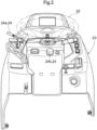
- Fig. 2 illustrates the manual operation tool group 24 included in the panel unit 23.
- the manual operation tool group 24 includes an autonomous travel start operation tool 24a and a teaching operation tool 24b as tools particularly relevant to the present invention.
- the autonomous travel start operation tool 24a is in the form of an operating lever
- the teaching operation tool 24b is in the form of a button switch.
- Fig. 3 schematically illustrates example tillage work performed by the tractor.
- the tillage work involves alternating between (i) straight travel during which the tractor travels along a linear work path while performing tillage work and (ii) turn travel through which the tractor moves to a subsequent linear work path.
- the tractor is manually driven to travel along the first linear work path, which serves as a teaching path TL.
- the tractor sets subsequent linear paths sequentially in such a pattern that the subsequent linear paths are next to one another and parallel to the teaching path TL.
- the subsequent linear paths each serve as a target travel path for autonomous travel, and are labeled as LM(1) to LM(6) in Fig. 3 .
- the description below deals with a basic travel process during the tillage work.
- the driver manually drives the tractor to position the vehicle body 1 at a teaching start point close to a ridge of the agricultural field, and then presses the teaching operation tool 24b.
- the driver manually drives the tractor to cause the vehicle body 1 to travel from the teaching start point linearly along the ridge to a teaching end point present on the opposite side and close to the ridge, and then presses the teaching operation tool 24b again.
- This allows a teaching path TL to be calculated from the position coordinates of the vehicle body 1 at the teaching start point and the position coordinate of the vehicle body 1 at the teaching end point, the teaching path TL connecting the teaching start point with the teaching end point.
- the driver causes the tractor to perform 180-degree turn travel (U-turn travel) to move to the first target travel path LM(1), which is adjacent to the teaching path TL.
- U-turn travel 180-degree turn travel
- the tractor checks whether the vehicle body 1 is directed suitably for subsequent tillage work, that is, the vehicle body 1 has a travel deviation relative to the target travel path LM(1) which travel deviation is within an acceptable range. If the travel deviation is within the acceptable range, the driver is notified that the tractor is able to travel autonomously along the target travel path LM(1). In response to the notification, the driver operates the autonomous travel start operation tool 24a. This causes the tractor to start autonomous travel with the target travel path LM(1) set as a target.
- the target travel path LM(1) is a target travel path LM along which the vehicle body 1 performs work travel first after teaching travel.
- the driver drives the tractor along a turn travel path (U-turn travel path).
- the tractor sets a subsequent target travel path LM(2) that is adjacent to the previous target travel path LM(1) and present on the side of an unworked region and that extends from a starting point position Ls(2).
- the tractor repeats setting a target travel path LM and performing work travel in the order of target travel paths LM(3), LM(4), LM(5), and LM(6) with turn travel in-between.
- Fig. 4 illustrates an example in which the move-off position Pb and the resumption position Pr coincide with each other.
- the move-off position Pb and the resumption position Pr may alternatively be two different positions.
- the resumption position may be at the travel starting end of the target travel path LM(4) (indicated as "Pr1" in Fig. 4 ). If, for instance, the tractor has moved off after finishing the travel along the target travel path LM(4), the move-off position will be at the travel ending end of the target travel path LM(4) (indicated as "Pb2" in Fig. 4 ), whereas the resumption position will be at the travel starting end of the subsequent target travel path LM(5) (indicated as "Pr2" in Fig. 4 ).
- the tractor includes a satellite positioning module 8a and an inertial positioning module 8b as included in the positioning unit 8.
- the satellite positioning module 8a has a satellite positioning function: it is capable of determining the position of the vehicle body 1 with use of a satellite positioning system configured to receive a radio wave from a satellite and detect the position of the vehicle body 1.
- the inertial positioning module 8b includes, for example, a gyro sensor and an acceleration sensor, and is thereby capable of detecting the angular velocity of a turn of the vehicle body 1.
- the inertial positioning module 8b is capable of integrating the angular velocity to determine an angular change in the vehicle body direction.
- the inertial positioning module 8b is preferably present at a low position on the vehicle body 1 which position is at the middle in the width direction of the vehicle body 1.
- the inertial positioning module 8b may alternatively be present at a different position, for example, where the satellite positioning module 8a is present.
- the control device 5 includes an input-output processing section 50 as an input-output interface.
- the input-output processing section 50 is connected to, for example, an operation device group 60, a state detector group 70, and the manual operation tool group 24.
- the positioning unit 8 is connected to the control device 5 over an in-vehicle LAN.
- the monitor 25 as a notification device includes a liquid crystal panel, and is configured to display various information items on the basis of a notification signal from a notification unit 72 configured to control notification.
- the notification unit 72 is also connected to the control device 5 over the in-vehicle LAN.
- the operation device group 60 includes a steering motor 14, a travel operation device 61 (which is a travel-related operation device), and a work operation device 62 (which is a work-related operation device).
- the state detector group 70 includes various sensors, switches, and the like such as a travel device state detector 74 and a work device state detector 75.
- the travel device state detector 74 includes travel state detecting sensors such as a vehicle speed sensor, a steering angle sensor, an engine rotation speed sensor, a brake pedal detecting sensor, and a parking brake detecting sensor (not illustrated in the drawings).
- the work device state detector 75 includes sensors for detecting the respective states of various mechanisms included in the work device 30 such as a lifting/lowering mechanism.
- the control device 5 includes a vehicle position calculating section 80, a travel direction calculating section 81, a travel control section 51, a work control section 52, a teaching management section 53, a path setting section 54, a travel deviation calculating section 55, a move-off recording section 56, and a work return management section 57.
- the vehicle position calculating section 80 calculates the map coordinates of the vehicle body 1 (that is, the vehicle position) on the basis of satellite positioning data transmitted sequentially from the positioning unit 8. During the calculation, the vehicle position calculating section 80 converts the position calculated directly from satellite positioning data into a benchmark point on the vehicle body 1 (for example, the position of the vehicle body center or of the work center of the work device 30).
- the travel direction calculating section 81 processes data on vehicle positions (calculated by the vehicle position calculating section 80) over time to calculate the travel direction of the vehicle body 1, that is, its front-back direction. The travel direction calculating section 81 may alternatively calculate the travel direction on the basis of measurement data from the inertial positioning module 8b.
- the travel control section 51 transmits a steering control signal to the steering motor 14, and also transmits, for example, a speed change control signal and a braking control signal to a travel operation device 61 such as a transmission (not illustrated in the drawings).
- the travel control section 51 includes an autonomous travel control section 511, a manual travel control section 512, and a travel mode management section 513 in order for the tractor to selectively travel autonomously or be driven manually.
- the work control section 52 controls various work operation devices 62 each configured to lift and lower the work device 30 or transmit power to the work device 30 while the vehicle body 1 is traveling.
- the teaching management section 53 calculates data on a teaching path TL (such as map coordinates) on the basis of the teaching travel described above.
- the path setting section 54 sets a target travel path as a target of autonomous travel through the procedure described above with reference to Fig. 3 .
- the travel deviation calculating section 55 calculates (i) a lateral deviation that the vehicle body 1 has at a vehicle position calculated by the vehicle position calculating section 80 and (ii) a directional deviation that the vehicle body 1 has at the vehicle position.
- a lateral deviation refers to the distance in the direction orthogonal to the direction of the target travel path between the benchmark point on the vehicle body 1 at the vehicle position and a target travel path set by the path setting section 54.
- a directional deviation refers to the angle formed by the travel direction of the vehicle body 1 calculated by the travel direction calculating section 81 and the target travel path.
- the tractor is set to an autonomous travel mode to drive itself autonomously or a manual travel mode to be driven manually. These travel modes are managed by the travel mode management section 513.
- the autonomous travel control section 511 computes, on the basis of a lateral deviation and a directional deviation from the travel deviation calculating section 55, a steering control amount intended to reduce the lateral deviation and the directional deviation.
- the steering motor 14 is driven (that is, the front wheels 11 are steered) on the basis of the steering control amount.
- the move-off recording section 56 records move-off information when the tractor has moved off the target travel path while performing agricultural field work during autonomous travel and headed for a parking area PA as illustrated in Fig. 4 .
- the move-off information is information related to the moving of the vehicle body 1 off the target travel path.
- the move-off information includes information on the move-off position (that is, the vehicle position that the vehicle body 1 had when it moved off), a move-off travel path (that is, the target travel path serving as a target for autonomous steering control when the tractor moved off), and the travel direction that the vehicle body 1 had on the move-off travel path.
- the work return management section 57 selects a resumption travel path, that is, a target travel path that the tractor having moved off a travel path will use when it resumes performing agricultural field work during autonomous travel.
- the work return management section 57 obtains data on a resumption travel path by reading move-off information from the move-off recording section 56.
- the work return management section 57 also manages return information, which is for use to guide the vehicle body 1 to the selected resumption travel path or move-off position.
- the return travel is performed manually.
- the resumption travel path or move-off position in the agricultural field is preferably shown on the monitor 25 for the driver.
- the return information includes such information for the monitor 25 to display as (i) image information on an agricultural field map with the resumption travel path and move-off position marked and (ii) text information indicative of the date and time of the moving off and/or the like.
- the work return management section 57 includes a determining section 571 configured to determine, while the agricultural field work vehicle is being manually driven for the vehicle body 1 to return to the resumption travel path, whether the agricultural field work vehicle is able to transition from manual travel to autonomous travel.
- the determining section 571 uses, as a condition for the transition to autonomous travel, a determination rule that corresponds to the current situation.
- the description below deals with example transition rules.
- the determining section 571 selectively uses the transition rules below to determine whether the agricultural field work vehicle is able to transition to autonomous travel.
- the description below of the example transition rules uses the same terms and reference signs as those in Fig. 4 .
- a first zone Z1 as a region extending over a predetermined distance from the line segment between the travel starting end (indicated as "Rs" in Fig. 6 ) of the resumption travel path LM(4) and the move-off position Pb. This is because if the vehicle body 1 returns onto the line segment between the travel ending end (indicated as "Re” in Fig.
- the determining section 571 may set a zone Z1, in which the agricultural field work vehicle is able to transition to autonomous travel, in a region astride the entire length of the resumption travel path LM(4).
- the determining section 571 selects the predetermined distance for the first zone Z1 such that the autonomous travel control section 511 is capable of computing an appropriate steering control amount on the basis of a lateral deviation and a directional deviation both calculated by the travel deviation calculating section 55.
- Determination Rule a allows the resumption position Pr to be any position on the line segment between the travel starting end RS and the move-off position Pb.
- the determining section 571 determines that the agricultural field work vehicle is able to transition to autonomous travel.
- the travel starting end Rs coincides with a resumption position Pr1.
- the second zone Z2 is thus in the shape of a semicircle (which may alternatively be a sector) that has a center at the travel starting end Rs and that is on the side of the U-turn travel path.
- the determining section 571 selects its radius such that the autonomous travel control section 511 is capable of computing an appropriate steering control amount on the basis of a lateral deviation and a directional deviation both calculated by the travel deviation calculating section 55.
- the vehicle body 1 performs redundant work or blank travel, that is, travels without performing work, along the line segment between the travel starting end Rs of the resumption travel path LM(4) and the move-off position Pb.
- the determining section 571 determines that the agricultural field work vehicle is able to transition to autonomous travel.
- the move-off position Pb coincides with a resumption position Pr.
- the third zone Z3 is thus in the shape of a semicircle (which may alternatively be a sector) that has a center at the move-off position Pb and that is on the upstream side of the resumption travel path LM(4) in the travel direction.
- the determining section 571 selects its radius or length to the outer edge such that the autonomous travel control section 511 is capable of computing an appropriate steering control amount on the basis of a lateral deviation and a directional deviation both calculated by the travel deviation calculating section 55.
- the move-off position Pb and the resumption position Pr coincide with each other, so that the vehicle body 1 substantially does not perform redundant work or blank travel.
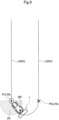
- the move-off position Pb2 coincides with the travel ending end (indicated as "Re” in Fig. 9 ) of the target travel path LM(4), and the resumption position Pr2 coincides with the travel starting end (indicated as "Rs” in Fig. 9 ) of the resumption travel path LM(5).
- the benchmark point indicated as "BP” in Fig. 9
- the determining section 571 determines that the agricultural field work vehicle is able to transition to autonomous travel.
- the travel starting end Rs coincides with a resumption position Pr2.
- the fourth zone Z4 is thus in the shape of a semicircle (which may alternatively be a sector) that has a center at the travel starting end Rs and that is on the side of the U-turn travel path.
- the determining section 571 selects its radius or length to the outer edge such that the autonomous travel control section 511 is capable of computing an appropriate steering control amount on the basis of a lateral deviation and a directional deviation both calculated by the travel deviation calculating section 55. Determination Rule d applies also to a case where the vehicle body 1 has moved off the U-turn travel path extending from the target travel path LM(4) to the subsequent target travel path LM(5).
- the above-described determination rules to which the determining section 571 refers are each intended to determine whether the vehicle body 1 is present within a predetermined zone, that is, whether the vehicle body 1 is present within a predetermined distance from the position at which the vehicle body 1 will resume autonomous travel. For the vehicle body 1 to enter a travel path, however, the direction of the vehicle body 1 is also an important factor.
- the present embodiment is thus arranged such that the above-described determination rules each further involve a determination condition of whether the deviation of the direction of the vehicle body 1 from the direction of the resumption travel path (that is, the direction in which the resumption travel path extends) is within an allowable deviation range.
- Whether a deviation is within the allowable deviation range means whether the crossing angle formed by a line indicative of the vehicle body direction and a line indicative of the direction of the resumption travel path is not larger than an allowable angle.
- the allowable angle is an angle within which the vehicle body 1 is able to enter a resumption travel path through autonomous steering smoothly without damaging the agricultural field.
- the work return management section 57 transmits to the notification unit 72 a notification command to notify the driver of the determination result.
- the notification unit 72 generates a notification signal to, for example, (i) cause the monitor 25 to display information indicating that the agricultural field work vehicle is able to transition to autonomous travel, (ii) turn on a lamp (not illustrated in the drawings), and/or (iii) cause a loudspeaker (not illustrated in the drawings) to emit a sound.
- the present embodiment is arranged such that after the determining section 571 has determined that the agricultural field work vehicle is able to transition from manual travel to autonomous travel to enter the resumption travel path, the driver operates the autonomous travel start operation tool 24a to start autonomous travel so that the front wheels 11 are controlled autonomously.
- the present embodiment may alternatively be arranged to allow autonomous travel to be started automatically, that is, without the operation of the autonomous travel start operation tool 24a.
- the present invention is applicable to any agricultural field work vehicle configured to travel autonomously along a target travel path in an agricultural field.
Landscapes
- Engineering & Computer Science (AREA)
- Mechanical Engineering (AREA)
- Automation & Control Theory (AREA)
- Life Sciences & Earth Sciences (AREA)
- Radar, Positioning & Navigation (AREA)
- Aviation & Aerospace Engineering (AREA)
- General Physics & Mathematics (AREA)
- Physics & Mathematics (AREA)
- Remote Sensing (AREA)
- Human Computer Interaction (AREA)
- Soil Sciences (AREA)
- Environmental Sciences (AREA)
- Transportation (AREA)
- Health & Medical Sciences (AREA)
- Medical Informatics (AREA)
- Game Theory and Decision Science (AREA)
- Evolutionary Computation (AREA)
- Artificial Intelligence (AREA)
- Business, Economics & Management (AREA)
- Guiding Agricultural Machines (AREA)
- Control Of Position, Course, Altitude, Or Attitude Of Moving Bodies (AREA)
- Control Of Driving Devices And Active Controlling Of Vehicle (AREA)
Description
- The present invention relates to an agricultural field work vehicle capable of traveling autonomously along a target travel path.
- An agricultural field work vehicle configured to travel autonomously along a target travel path suspends work for any of various reasons and moves off the target travel path. An agricultural field work vehicle is required to move off a target travel path while performing work for lack of fuel or due to a limit on the work capacity (such as a limit on the harvest capacity or addition of an agent to be supplied to the agricultural field). The agricultural field work vehicle moves to a particular place to overcome a circumstance that required the agricultural field work vehicle to move off the target travel path, and then returns to the position at which the agricultural field work vehicle moved off the target travel path. At that position, the agricultural field work vehicle resumes performing work during autonomous travel.
-
Japanese unexamined patent application publication, Tokukai, No. 2018-116613 - Document
US 2018/206391 A1 describes a travel control apparatus for a work vehicle including a display and a circuitry. The display is to display a position of the work vehicle. The circuitry is configured to display in the display a guide index via which the work vehicle is manually guided to an automatic-travel permitted area in which the work vehicle is configured to automatically travel, and to determine whether the work vehicle is located in the automatic-travel permitted area. - Document
US 2017/177002 A1 describes an autonomous travel work vehicle, which is provided with a position calculation means that measures the device body position by means of a satellite positioning system, a steering actuator that operates a steering device, an engine rotation control means, a transmission means, and a control device that controls each of same, is caused to autonomously travel, along a set travel path stored in the control device, by an accompanying travel work vehicle that works while accompanying the travel of the autonomous travel work vehicle by means of attended operation and that is mounted with a remote operation device that can operate the autonomous travel work vehicle, and the control device halts autonomous travel when a signal disruption from the satellites, a large deviation from the set travel path, an abnormal sensor value, fuel exhaustion, or the like is detected. - Document
JP 2018/073399 A1 - The work vehicle disclosed in
JP 2018-116613 - In view of the above circumstances, it is an object of the present invention to provide an agricultural field work vehicle capable of, after suspending agricultural field work during autonomous travel and moving off a target travel path, resuming autonomous travel smoothly at a desired work resumption position.
- The claimed invention is defined by the features set forth in the appended independent claim. Additional embodiments of the claimed invention are defined by the dependent claims.
- With the claimed arrangement, if the agricultural field work vehicle has moved off a target travel path for refueling or rest of the driver, the agricultural field work vehicle records either or both of the move-off position and the move-off travel path as move-off information. When resuming the agricultural field work, the agricultural field work vehicle selects, on the basis of the move-off information, an initial target travel path (resumption travel path) on which the agricultural field work vehicle will resume traveling autonomously. When the agricultural field work vehicle has been driven manually to a position near the selected target travel path, the determining section determines whether the agricultural field work vehicle is able to transition smoothly from manual travel to autonomous travel. The determining section determines, for instance, whether the autonomous travel control system has located the resumption travel path and/or whether the agricultural field work vehicle will be able to travel autonomously along the resumption travel path without a steering operation so large as to damage the agricultural field. Thus, if the determining section has determined that the agricultural field work vehicle will be able to travel autonomously, the agricultural field work vehicle will transition smoothly from manual travel to autonomous travel.
- A further embodiment of the present invention further includes: a manual operation tool configured to start autonomous travel by the vehicle body, wherein after the determining section has determined that the agricultural field work vehicle is able to perform the transition, the manual operation tool is operated to cause the autonomous travel control section to start the autonomous travel by the vehicle body. This embodiment is arranged to transition from manual travel to autonomous travel under a transition condition of whether the determining section has determined that the agricultural field work vehicle is able to transition to autonomous travel and a transition condition of whether the manual operation tool has been operated. With this arrangement, the determining section ensures smooth transition. If the driver performs a manual operation for a command to transition from manual travel to autonomous travel, it will not cause the agricultural field work vehicle to damage the agricultural field. Further, since a person such as the driver causes the agricultural field work vehicle to start traveling autonomously, the driver will not be surprised by a sudden start of autonomous travel.
- A further embodiment of the present invention is further arranged such that in a case where the determining section has determined that the agricultural field work vehicle is able to perform the transition, the determining section transmits to a notification unit a notification command to notify a driver that the transition is allowable. This embodiment is arranged to, if the determining section has determined that the agricultural field work vehicle is able to transition from manual travel to autonomous travel, notify the driver that the agricultural field work vehicle is allowed to travel autonomously. This allows the driver to be ready for automatic transition to autonomous travel. Further, in a case where the driver definitively selects to cause the agricultural field work vehicle to transition to autonomous travel, the driver can cause the agricultural field work vehicle at a desired time point to transition smoothly to autonomous travel because the control device ensures that the agricultural field work vehicle is able to transition to autonomous travel.
- Smooth transition from manual travel to autonomous travel depends on a plurality of conditions, one of which is whether the vehicle body is close to a resumption travel path, that is, that target travel path on which the agricultural field work vehicle will travel autonomously. If the vehicle body is close enough to a resumption travel path for the control system to accurately locate the resumption travel path, the control system can calculate a positional deviation of the vehicle body from the resumption travel path. After calculating a positional deviation, the control system generates a steering signal intended to reduce the positional deviation. This allows the vehicle body to travel autonomously along the resumption travel path. If the vehicle body is apart excessively from a resumption travel path, the control system is unable to locate the resumption travel path. The control system is able to locate a resumption travel path within an experimentally or theoretically calculated zone. A further embodiment of the present invention is thus further arranged such that in response to the vehicle body having entered a zone set near the resumption travel path, the determining section determines that the agricultural field work vehicle is able to perform the transition.
- In a case where the agricultural field work vehicle has suspended autonomous travel along a target travel path and moved off the target travel path partway, the agricultural field work vehicle may resume the autonomous travel not at the move-off position but at the travel starting end of the target travel path. In such a case, the agricultural field work vehicle performs no work or redundant work from the resumption position to the move-off position. The agricultural field work vehicle may resume the autonomous travel at the travel starting end of the target travel path because the agricultural field work vehicle is more likely to transition smoothly to autonomous travel in the case where the vehicle body enters the target travel path at the travel starting end than in the case where the vehicle body enters the target travel path at the intermediate, move-off position. A further disclosure is that in response to the vehicle body having entered a zone set near a travel starting end of the resumption travel path, the determining section determines that the agricultural field work vehicle is able to perform the transition.
- If the agricultural field work vehicle has moved off a target travel path partway, the agricultural field work vehicle is able to enter the target travel path (resumption travel path) at the move-off position from a side of the target travel path. A further disclosure is that in response to the vehicle body having entered a zone set near the move-off position, the determining section determines that the agricultural field work vehicle is able to perform the transition.
- The agricultural field work vehicle is able to enter a resumption travel path more smoothly when the direction of the vehicle body (that is, its front-back direction) is closer to the direction of the resumption travel path (that is, the direction in which the resumption travel path extends). The determination section preferably further uses a determination condition about the direction of the vehicle body in determining whether the agricultural field work vehicle is able to transition from manual travel to autonomous travel. A further embodiment of the present invention is thus further arranged such that the determining section further determines, as a condition for determining whether the agricultural field work vehicle is able to transition, whether the vehicle body has a directional deviation from the resumption travel path which directional deviation is within an allowable deviation range.
-
-
Fig. 1 is a side view of a tractor. -
Fig. 2 is a perspective view of an autonomous travel start operation tool and a teaching operation tool. -
Fig. 3 is a diagram illustrating travel paths along which a tractor performs tillage work. -
Fig. 4 is a diagram illustrating how a tractor performs move-off travel and return travel. -
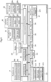
Fig. 5 is a functional block diagram illustrating a control system of a tractor. -
Fig. 6 is a diagram illustrating a determination rule under which a tractor having moved off a travel path resumes autonomous travel. -
Fig. 7 is a diagram illustrating a determination rule under which a tractor having moved off a travel path resumes autonomous travel. -
Fig. 8 is a diagram illustrating a determination rule under which a tractor having moved off a travel path resumes autonomous travel. -
Fig. 9 is a diagram illustrating a determination rule under which a tractor having moved off a travel path resumes autonomous travel. - The description below deals with, as an embodiment of the present invention, an agricultural field work vehicle configured to travel autonomously along a target travel path.
Fig. 1 is a side view of a tractor as an example of such an agricultural field work vehicle. As illustrated inFig. 1 , the tractor includesfront wheels 11,rear wheels 12, avehicle body 1 supported by thefront wheels 11 and therear wheels 12, and acab 20 at a central portion of thevehicle body 1. The tractor is provided with a rotary tiller device as awork device 30 attached to a back portion of thevehicle body 1 via a hydraulic lifting/lowering mechanism. Thefront wheels 11 function to steer the tractor: changing their steering angle changes the direction in which the tractor travels. The steering angle of thefront wheels 11 is changed through operation of asteering mechanism 13. Thesteering mechanism 13 includes asteering motor 14 for autonomous steering during autonomous travel. During manual travel, thefront wheels 11 are controlled through operation of asteering wheel 22 provided in thecab 20. The tractor includes apositioning unit 8 that is present at an upper portion of acabin 21 defining thecab 20 and that is configured to detect the vehicle position. The tractor includes apanel unit 23 near thesteering wheel 22. - The
panel unit 23 includes a manualoperation tool group 24 and amonitor 25 provided with a touch screen.Fig. 2 illustrates the manualoperation tool group 24 included in thepanel unit 23. The manualoperation tool group 24 includes an autonomous travelstart operation tool 24a and ateaching operation tool 24b as tools particularly relevant to the present invention. For the present embodiment, the autonomous travelstart operation tool 24a is in the form of an operating lever, whereas theteaching operation tool 24b is in the form of a button switch. -
Fig. 3 schematically illustrates example tillage work performed by the tractor. The tillage work involves alternating between (i) straight travel during which the tractor travels along a linear work path while performing tillage work and (ii) turn travel through which the tractor moves to a subsequent linear work path. The tractor is manually driven to travel along the first linear work path, which serves as a teaching path TL. The tractor sets subsequent linear paths sequentially in such a pattern that the subsequent linear paths are next to one another and parallel to the teaching path TL. The subsequent linear paths each serve as a target travel path for autonomous travel, and are labeled as LM(1) to LM(6) inFig. 3 . - The description below deals with a basic travel process during the tillage work. To start tillage work, the driver manually drives the tractor to position the
vehicle body 1 at a teaching start point close to a ridge of the agricultural field, and then presses theteaching operation tool 24b. The driver manually drives the tractor to cause thevehicle body 1 to travel from the teaching start point linearly along the ridge to a teaching end point present on the opposite side and close to the ridge, and then presses theteaching operation tool 24b again. This allows a teaching path TL to be calculated from the position coordinates of thevehicle body 1 at the teaching start point and the position coordinate of thevehicle body 1 at the teaching end point, the teaching path TL connecting the teaching start point with the teaching end point. - After the teaching path TL has been set, the driver causes the tractor to perform 180-degree turn travel (U-turn travel) to move to the first target travel path LM(1), which is adjacent to the teaching path TL.
- Before or after the end of the turn travel, the tractor checks whether the
vehicle body 1 is directed suitably for subsequent tillage work, that is, thevehicle body 1 has a travel deviation relative to the target travel path LM(1) which travel deviation is within an acceptable range. If the travel deviation is within the acceptable range, the driver is notified that the tractor is able to travel autonomously along the target travel path LM(1). In response to the notification, the driver operates the autonomous travelstart operation tool 24a. This causes the tractor to start autonomous travel with the target travel path LM(1) set as a target. - After starting autonomous travel, the tractor steers itself autonomously so that the
vehicle body 1 remains along the target travel path LM(1). The target travel path LM(1) is a target travel path LM along which thevehicle body 1 performs work travel first after teaching travel. When the autonomous travel along the target travel path LM(1) has ended, the driver drives the tractor along a turn travel path (U-turn travel path). Then, the tractor sets a subsequent target travel path LM(2) that is adjacent to the previous target travel path LM(1) and present on the side of an unworked region and that extends from a starting point position Ls(2). Subsequently, the tractor repeats setting a target travel path LM and performing work travel in the order of target travel paths LM(3), LM(4), LM(5), and LM(6) with turn travel in-between. - As illustrated in
Fig. 4 , if the tractor encounters a circumstance while performing work during autonomous travel which circumstance requires the tractor to move off the current travel path, the driver stops the autonomous travel and manually drives the tractor from a move-off position (indicated as "Pb" or "Pb2" inFig. 4 ) to a parking area PA. When the circumstance has been overcome, the driver manually drives the tractor from the parking area PA to a resumption position (indicated as "Pr" or "Pr2" inFig. 4 ), where the tractor resumes performing work during autonomous travel. -
Fig. 4 illustrates an example in which the move-off position Pb and the resumption position Pr coincide with each other. The move-off position Pb and the resumption position Pr may alternatively be two different positions. For instance, since the tractor has moved off at the move-off position Pb during travel along the target travel path LM(4), the resumption position may be at the travel starting end of the target travel path LM(4) (indicated as "Pr1" inFig. 4 ). If, for instance, the tractor has moved off after finishing the travel along the target travel path LM(4), the move-off position will be at the travel ending end of the target travel path LM(4) (indicated as "Pb2" inFig. 4 ), whereas the resumption position will be at the travel starting end of the subsequent target travel path LM(5) (indicated as "Pr2" inFig. 4 ). - The description below deals with functional sections of a control system of the tractor with reference to
Fig. 5 . The tractor includes asatellite positioning module 8a and aninertial positioning module 8b as included in thepositioning unit 8. Thesatellite positioning module 8a has a satellite positioning function: it is capable of determining the position of thevehicle body 1 with use of a satellite positioning system configured to receive a radio wave from a satellite and detect the position of thevehicle body 1. Theinertial positioning module 8b includes, for example, a gyro sensor and an acceleration sensor, and is thereby capable of detecting the angular velocity of a turn of thevehicle body 1. Theinertial positioning module 8b is capable of integrating the angular velocity to determine an angular change in the vehicle body direction. Theinertial positioning module 8b is preferably present at a low position on thevehicle body 1 which position is at the middle in the width direction of thevehicle body 1. Theinertial positioning module 8b may alternatively be present at a different position, for example, where thesatellite positioning module 8a is present. - The
control device 5 includes an input-output processing section 50 as an input-output interface. The input-output processing section 50 is connected to, for example, anoperation device group 60, astate detector group 70, and the manualoperation tool group 24. Thepositioning unit 8 is connected to thecontrol device 5 over an in-vehicle LAN. Themonitor 25 as a notification device includes a liquid crystal panel, and is configured to display various information items on the basis of a notification signal from anotification unit 72 configured to control notification. Thenotification unit 72 is also connected to thecontrol device 5 over the in-vehicle LAN. - The
operation device group 60 includes asteering motor 14, a travel operation device 61 (which is a travel-related operation device), and a work operation device 62 (which is a work-related operation device). - The
state detector group 70 includes various sensors, switches, and the like such as a traveldevice state detector 74 and a workdevice state detector 75. The traveldevice state detector 74 includes travel state detecting sensors such as a vehicle speed sensor, a steering angle sensor, an engine rotation speed sensor, a brake pedal detecting sensor, and a parking brake detecting sensor (not illustrated in the drawings). The workdevice state detector 75 includes sensors for detecting the respective states of various mechanisms included in thework device 30 such as a lifting/lowering mechanism. - The
control device 5 includes a vehicleposition calculating section 80, a traveldirection calculating section 81, atravel control section 51, awork control section 52, ateaching management section 53, apath setting section 54, a traveldeviation calculating section 55, a move-offrecording section 56, and a workreturn management section 57. - The vehicle
position calculating section 80 calculates the map coordinates of the vehicle body 1 (that is, the vehicle position) on the basis of satellite positioning data transmitted sequentially from thepositioning unit 8. During the calculation, the vehicleposition calculating section 80 converts the position calculated directly from satellite positioning data into a benchmark point on the vehicle body 1 (for example, the position of the vehicle body center or of the work center of the work device 30). The traveldirection calculating section 81 processes data on vehicle positions (calculated by the vehicle position calculating section 80) over time to calculate the travel direction of thevehicle body 1, that is, its front-back direction. The traveldirection calculating section 81 may alternatively calculate the travel direction on the basis of measurement data from theinertial positioning module 8b. - The
travel control section 51 transmits a steering control signal to thesteering motor 14, and also transmits, for example, a speed change control signal and a braking control signal to atravel operation device 61 such as a transmission (not illustrated in the drawings). Thetravel control section 51 includes an autonomoustravel control section 511, a manualtravel control section 512, and a travelmode management section 513 in order for the tractor to selectively travel autonomously or be driven manually. - The
work control section 52 controls variouswork operation devices 62 each configured to lift and lower thework device 30 or transmit power to thework device 30 while thevehicle body 1 is traveling. - The
teaching management section 53 calculates data on a teaching path TL (such as map coordinates) on the basis of the teaching travel described above. Thepath setting section 54 sets a target travel path as a target of autonomous travel through the procedure described above with reference toFig. 3 . - The travel
deviation calculating section 55 calculates (i) a lateral deviation that thevehicle body 1 has at a vehicle position calculated by the vehicleposition calculating section 80 and (ii) a directional deviation that thevehicle body 1 has at the vehicle position. A lateral deviation refers to the distance in the direction orthogonal to the direction of the target travel path between the benchmark point on thevehicle body 1 at the vehicle position and a target travel path set by thepath setting section 54. A directional deviation refers to the angle formed by the travel direction of thevehicle body 1 calculated by the traveldirection calculating section 81 and the target travel path. - The tractor is set to an autonomous travel mode to drive itself autonomously or a manual travel mode to be driven manually. These travel modes are managed by the travel
mode management section 513. When the tractor is in the autonomous travel mode, the autonomoustravel control section 511 computes, on the basis of a lateral deviation and a directional deviation from the traveldeviation calculating section 55, a steering control amount intended to reduce the lateral deviation and the directional deviation. Thesteering motor 14 is driven (that is, thefront wheels 11 are steered) on the basis of the steering control amount. - The move-off
recording section 56 records move-off information when the tractor has moved off the target travel path while performing agricultural field work during autonomous travel and headed for a parking area PA as illustrated inFig. 4 . The move-off information is information related to the moving of thevehicle body 1 off the target travel path. The move-off information includes information on the move-off position (that is, the vehicle position that thevehicle body 1 had when it moved off), a move-off travel path (that is, the target travel path serving as a target for autonomous steering control when the tractor moved off), and the travel direction that thevehicle body 1 had on the move-off travel path. - The work
return management section 57 selects a resumption travel path, that is, a target travel path that the tractor having moved off a travel path will use when it resumes performing agricultural field work during autonomous travel. The workreturn management section 57 obtains data on a resumption travel path by reading move-off information from the move-offrecording section 56. The workreturn management section 57 also manages return information, which is for use to guide thevehicle body 1 to the selected resumption travel path or move-off position. The return travel is performed manually. The resumption travel path or move-off position in the agricultural field is preferably shown on themonitor 25 for the driver. The return information includes such information for themonitor 25 to display as (i) image information on an agricultural field map with the resumption travel path and move-off position marked and (ii) text information indicative of the date and time of the moving off and/or the like. - The work
return management section 57 includes a determiningsection 571 configured to determine, while the agricultural field work vehicle is being manually driven for thevehicle body 1 to return to the resumption travel path, whether the agricultural field work vehicle is able to transition from manual travel to autonomous travel. The determiningsection 571 uses, as a condition for the transition to autonomous travel, a determination rule that corresponds to the current situation. The description below deals with example transition rules. The determiningsection 571 selectively uses the transition rules below to determine whether the agricultural field work vehicle is able to transition to autonomous travel. The description below of the example transition rules uses the same terms and reference signs as those inFig. 4 . - If the benchmark point (indicated as "BP" in
Fig. 6 ) on thevehicle body 1 has entered a first zone (indicated as "Z1" inFig. 6 ) set astride a portion of the resumption travel path LM(4), the determiningsection 571 determines that the agricultural field work vehicle is able to transition to autonomous travel.Fig. 6 illustrates a first zone Z1 as a region extending over a predetermined distance from the line segment between the travel starting end (indicated as "Rs" inFig. 6 ) of the resumption travel path LM(4) and the move-off position Pb. This is because if thevehicle body 1 returns onto the line segment between the travel ending end (indicated as "Re" inFig. 6 ) of the resumption travel path LM(4) and the move-off position Pb, and the agricultural field work vehicle transitions to autonomous travel, the agricultural field work vehicle will end up leaving an unworked region between the return position and the move-off position Pb. If such an unworked region may be left, the determiningsection 571 may set a zone Z1, in which the agricultural field work vehicle is able to transition to autonomous travel, in a region astride the entire length of the resumption travel path LM(4). The determiningsection 571 selects the predetermined distance for the first zone Z1 such that the autonomoustravel control section 511 is capable of computing an appropriate steering control amount on the basis of a lateral deviation and a directional deviation both calculated by the traveldeviation calculating section 55. Determination Rule a allows the resumption position Pr to be any position on the line segment between the travel starting end RS and the move-off position Pb. - If the benchmark point (indicated as "BP" in
Fig. 7 ) on thevehicle body 1 has entered a second zone (indicated as "Z2" inFig. 7 ) set in the vicinity of the travel starting end (indicated as "Rs" inFig. 7 ) of the resumption travel path LM(4), the determiningsection 571 determines that the agricultural field work vehicle is able to transition to autonomous travel. In this example, the travel starting end Rs coincides with a resumption position Pr1. The second zone Z2 is thus in the shape of a semicircle (which may alternatively be a sector) that has a center at the travel starting end Rs and that is on the side of the U-turn travel path. The determiningsection 571 selects its radius such that the autonomoustravel control section 511 is capable of computing an appropriate steering control amount on the basis of a lateral deviation and a directional deviation both calculated by the traveldeviation calculating section 55. Under Determination Rule b, thevehicle body 1 performs redundant work or blank travel, that is, travels without performing work, along the line segment between the travel starting end Rs of the resumption travel path LM(4) and the move-off position Pb. - If the benchmark point (indicated as "BP" in
Fig. 8 ) on thevehicle body 1 has entered a third zone (indicated as "Z3" inFig. 8 ) set around the move-off position Pb, the determiningsection 571 determines that the agricultural field work vehicle is able to transition to autonomous travel. In this example, the move-off position Pb coincides with a resumption position Pr. The third zone Z3 is thus in the shape of a semicircle (which may alternatively be a sector) that has a center at the move-off position Pb and that is on the upstream side of the resumption travel path LM(4) in the travel direction. The determiningsection 571 selects its radius or length to the outer edge such that the autonomoustravel control section 511 is capable of computing an appropriate steering control amount on the basis of a lateral deviation and a directional deviation both calculated by the traveldeviation calculating section 55. Under Determination Rule c, the move-off position Pb and the resumption position Pr coincide with each other, so that thevehicle body 1 substantially does not perform redundant work or blank travel. - Under the fourth determination rule, which is similar to Determination Rule b, the move-off position Pb2 coincides with the travel ending end (indicated as "Re" in
Fig. 9 ) of the target travel path LM(4), and the resumption position Pr2 coincides with the travel starting end (indicated as "Rs" inFig. 9 ) of the resumption travel path LM(5). Thus, if the benchmark point (indicated as "BP" inFig. 9 ) on thevehicle body 1 has entered a fourth zone (indicated as "Z4" inFig. 9 ) set around the move-off position Pb, the determiningsection 571 determines that the agricultural field work vehicle is able to transition to autonomous travel. In this example, the travel starting end Rs coincides with a resumption position Pr2. The fourth zone Z4 is thus in the shape of a semicircle (which may alternatively be a sector) that has a center at the travel starting end Rs and that is on the side of the U-turn travel path. The determiningsection 571 selects its radius or length to the outer edge such that the autonomoustravel control section 511 is capable of computing an appropriate steering control amount on the basis of a lateral deviation and a directional deviation both calculated by the traveldeviation calculating section 55. Determination Rule d applies also to a case where thevehicle body 1 has moved off the U-turn travel path extending from the target travel path LM(4) to the subsequent target travel path LM(5). - The above-described determination rules to which the determining
section 571 refers are each intended to determine whether thevehicle body 1 is present within a predetermined zone, that is, whether thevehicle body 1 is present within a predetermined distance from the position at which thevehicle body 1 will resume autonomous travel. For thevehicle body 1 to enter a travel path, however, the direction of thevehicle body 1 is also an important factor. The present embodiment is thus arranged such that the above-described determination rules each further involve a determination condition of whether the deviation of the direction of thevehicle body 1 from the direction of the resumption travel path (that is, the direction in which the resumption travel path extends) is within an allowable deviation range. Whether a deviation is within the allowable deviation range means whether the crossing angle formed by a line indicative of the vehicle body direction and a line indicative of the direction of the resumption travel path is not larger than an allowable angle. The allowable angle is an angle within which thevehicle body 1 is able to enter a resumption travel path through autonomous steering smoothly without damaging the agricultural field. - When the determining
section 571 has determined that the agricultural field work vehicle is able to transition from manual travel to autonomous travel to enter the resumption travel path, the workreturn management section 57 transmits to the notification unit 72 a notification command to notify the driver of the determination result. In response to the notification command, thenotification unit 72 generates a notification signal to, for example, (i) cause themonitor 25 to display information indicating that the agricultural field work vehicle is able to transition to autonomous travel, (ii) turn on a lamp (not illustrated in the drawings), and/or (iii) cause a loudspeaker (not illustrated in the drawings) to emit a sound. - The present embodiment is arranged such that after the determining
section 571 has determined that the agricultural field work vehicle is able to transition from manual travel to autonomous travel to enter the resumption travel path, the driver operates the autonomous travelstart operation tool 24a to start autonomous travel so that thefront wheels 11 are controlled autonomously. The present embodiment may alternatively be arranged to allow autonomous travel to be started automatically, that is, without the operation of the autonomous travelstart operation tool 24a. -
- (1) The embodiment described above uses
front wheels 11 to steer avehicle body 1 and asteering motor 14 as a steering device. If the embodiment instead uses crawler-type travel devices as a steering system, the autonomoustravel control section 511 will control devices configured to change the respective speeds of the left and right crawlers. - (2) The embodiment described above involves linear target travel paths. The target travel paths may alternatively each extend in a curve with a large radius of curvature.
- (3) The embodiment described above is arranged such that the driver performs teaching travel first and that the
path setting section 54 then sets target travel paths on the basis of a teaching path calculated as a result of the teaching travel. The embodiment may alternatively be arranged such that the driver does not perform teaching travel and that thepath setting section 54 generates and sets all target travel paths automatically on the basis of, for example, the shape of the agricultural field. - (4) The functional sections shown in
Fig. 5 are grouped mainly for the purpose of description. The functional sections may alternatively each be integral with another functional section(s) or be divided further into a plurality of different functional sections. Further, at least part of the functional sections included in thecontrol device 5 may alternatively be included in a data processing terminal connected to the in-vehicle LAN of the work vehicle. - (5) The
control device 5 is not necessarily provided for thevehicle body 1; part or all of thecontrol device 5 may alternatively be present outside thevehicle body 1 in such a state as to be capable of data communication with thevehicle body 1. The embodiment described above may alternatively be arranged, for instance, such that thecontrol device 5 is mounted on a communication terminal or management computer and that the communication terminal or management computer transmits and receives necessary information to and from thevehicle body 1. - (6) The
control device 5 may have any configuration as long as it allows functions and processes similar to those described above to be performed. The functions and processes may be achieved by means of hardware or software. If the functions and processes are to be achieved by means of software, the programs are stored in a storage section and executed by a processor such as a CPU or an ECU included in, for example, thecontrol device 5. - (7) The embodiment described above of the present invention is a tractor provided with the control device for the present invention. The control device may alternatively be mounted on other agricultural field work vehicles such as combines and rice transplanters for preferable performance of autonomous travel.
- The present invention is applicable to any agricultural field work vehicle configured to travel autonomously along a target travel path in an agricultural field.
-
- 1
- Vehicle body
- 5
- Control device
- 8
- Positioning unit
- 8a
- Satellite positioning module
- 8b
- Inertial positioning module
- 11
- Front wheel
- 12
- Rear wheel
- 13
- Steering mechanism
- 14
- Steering motor
- 24
- Manual operation tool group
- 24a
- Autonomous travel start operation tool
- 24b
- Teaching operation tool
- 25
- Monitor
- 51
- Travel control section
- 511
- Autonomous travel control section
- 53
- Teaching management section
- 54
- Path setting section
- 55
- Travel deviation calculating section
- 56
- Move-off recording section
- 57
- Work return management section
- 571
- Determining section
- 72
- Notification unit
- 80
- Vehicle position calculating section
- 81
- Travel direction calculating section
Claims (4)
- An agricultural field work vehicle, comprising:a vehicle position calculating section (80) configured to calculate, as a vehicle position, a position of a vehicle body (1) of the agricultural field work vehicle in an agricultural field;an autonomous travel control section (511) configured to steer the vehicle body (1) so that the vehicle body (1) travels autonomously along each of a plurality of target travel paths with a U-turn travel path in-between, each target travel path being set to extend linearly from a starting point position to an ending end position;a move-off recording section (56) configured to record, as move-off information, either or both of a move-off position (Pb) and a move-off travel path, the move-off information being information related to the vehicle body (1) having moved off the target travel path (LM) while performing agricultural field work during the autonomous travel, the move-off position (Pb) being the vehicle position at a time when the vehicle body (1) moved off the target travel path (LM), the move-off travel path being the target travel path off which the vehicle body (1) moved; anda work return management section (57) configured to (i) select a resumption travel path on a basis of the move-off information, the resumption travel path being the target travel path (LM) on which the agricultural field work vehicle, after the vehicle body (1) moved off the target travel path, resumes performing the agricultural field work during the autonomous travel, and (ii) manage a return of the vehicle body (1) to the resumption travel path or a return of the vehicle body (1) to the move-off position (Pb), characterized in thatthe work return management section (57) includes a determining section (571) configured to determine, while the agricultural field work vehicle is being manually driven for the vehicle body (1) to return to the resumption travel path, whether the agricultural field work vehicle is able to transition from manual travel to autonomous travel,the resumption travel path is the target travel path having the move-off position (Pb) partway,in response to a benchmark point of the vehicle body (1) entering a zone extending over a predetermined distance from a line segment between the starting point position and the move-off position (Pb) of the resumption travel path, the determining section (571) determines that the agricultural field work vehicle is able to transition to the autonomous travel, andthe resumption travel path has a resumption position (Pr) at which the agricultural field work vehicle resumes performing the agricultural field work during the autonomous travel, the resumption position (Pr) being on the line segment.
- The agricultural field work vehicle according to claim 1, further comprising:a manual operation tool (24) configured to start the autonomous travel by the vehicle body (1), whereinafter the determining section (571) has determined that the agricultural field work vehicle is able to perform the transition, the manual operation tool (24) is operated to cause the autonomous travel control section (511) to start the autonomous travel by the vehicle body (1).
- The agricultural field work vehicle according to claim 1 or 2, wherein
in a case where the determining section (571) has determined that the agricultural field work vehicle is able to perform the transition, the determining section is configured to transmit to a notification unit (72) a notification command to notify a driver that the transition is allowable. - The agricultural field work vehicle according to any one of claims 1 to 3, wherein
the determining section (571) is further configured to determine, as a condition for determining whether the agricultural field work vehicle is able to transition, whether the vehicle body (1) has a directional deviation from the resumption travel path which directional deviation is within an allowable deviation range.
Applications Claiming Priority (2)
| Application Number | Priority Date | Filing Date | Title |
|---|---|---|---|
| JP2018238893A JP7206105B2 (en) | 2018-12-20 | 2018-12-20 | field work vehicle |
| PCT/JP2019/048370 WO2020129759A1 (en) | 2018-12-20 | 2019-12-11 | Field operation vehicle |
Publications (3)
| Publication Number | Publication Date |
|---|---|
| EP3900509A1 EP3900509A1 (en) | 2021-10-27 |
| EP3900509A4 EP3900509A4 (en) | 2022-09-21 |
| EP3900509B1 true EP3900509B1 (en) | 2024-09-04 |
Family
ID=71102088
Family Applications (1)
| Application Number | Title | Priority Date | Filing Date |
|---|---|---|---|
| EP19899894.0A Active EP3900509B1 (en) | 2018-12-20 | 2019-12-11 | Field operation vehicle |
Country Status (4)
| Country | Link |
|---|---|
| US (1) | US20220030758A1 (en) |
| EP (1) | EP3900509B1 (en) |
| JP (1) | JP7206105B2 (en) |
| WO (1) | WO2020129759A1 (en) |
Families Citing this family (7)
| Publication number | Priority date | Publication date | Assignee | Title |
|---|---|---|---|---|
| US11789458B2 (en) * | 2020-03-06 | 2023-10-17 | Catepillar Paving Products, Inc. | Automatic mode resume system for a mobile machine |
| CN113602286A (en) * | 2020-08-06 | 2021-11-05 | 上海司南卫星导航技术股份有限公司 | Method for automatic/auxiliary driving of agricultural vehicle, steering wheel and computer readable medium |
| JP7716866B2 (en) * | 2021-03-29 | 2025-08-01 | 三菱重工業株式会社 | Monitoring plan creation device, monitoring system, monitoring plan creation method and program |
| JP7386403B2 (en) * | 2021-05-27 | 2023-11-27 | 井関農機株式会社 | work vehicle |
| US20230159063A1 (en) * | 2021-11-22 | 2023-05-25 | Motional Ad Llc | Autonomous Driving Mode Engagement |
| JP2023081438A (en) * | 2021-12-01 | 2023-06-13 | ヤンマーホールディングス株式会社 | Automatic driving method, working vehicle and automatic driving system |
| WO2023180885A1 (en) * | 2022-03-23 | 2023-09-28 | Ricoh Company, Ltd. | Information processing system, autonomous traveling body, information processing apparatus, method for controlling autonomous traveling body and recording medium |
Family Cites Families (5)
| Publication number | Priority date | Publication date | Assignee | Title |
|---|---|---|---|---|
| KR20240134061A (en) * | 2014-02-06 | 2024-09-05 | 얀마 파워 테크놀로지 가부시키가이샤 | Parallel travel work system |
| KR102698059B1 (en) * | 2016-03-09 | 2024-08-22 | 얀마 파워 테크놀로지 가부시키가이샤 | Work vehicle and travel region specification device |
| JP6920958B2 (en) * | 2016-10-26 | 2021-08-18 | 株式会社クボタ | Travel route generator |
| JP6735685B2 (en) * | 2017-01-20 | 2020-08-05 | 株式会社クボタ | Travel control device |
| JP6804999B2 (en) * | 2017-01-20 | 2020-12-23 | 株式会社クボタ | Work driving management system |
-
2018
- 2018-12-20 JP JP2018238893A patent/JP7206105B2/en active Active
-
2019
- 2019-12-11 US US17/297,524 patent/US20220030758A1/en not_active Abandoned
- 2019-12-11 WO PCT/JP2019/048370 patent/WO2020129759A1/en not_active Ceased
- 2019-12-11 EP EP19899894.0A patent/EP3900509B1/en active Active
Also Published As
| Publication number | Publication date |
|---|---|
| JP7206105B2 (en) | 2023-01-17 |
| US20220030758A1 (en) | 2022-02-03 |
| EP3900509A1 (en) | 2021-10-27 |
| WO2020129759A1 (en) | 2020-06-25 |
| EP3900509A4 (en) | 2022-09-21 |
| JP2020100235A (en) | 2020-07-02 |
Similar Documents
| Publication | Publication Date | Title |
|---|---|---|
| EP3900509B1 (en) | Field operation vehicle | |
| US10474153B2 (en) | Work vehicle, slope travel control system for work vehicle, and slope travel control method for work vehicle | |
| US11937526B2 (en) | Control device for work vehicle configured to travel autonomously | |
| CN109152330B (en) | System for generating field travel route and field work vehicle | |
| US9248858B2 (en) | Trailer backup assist system | |
| US9969428B2 (en) | Trailer backup assist system with waypoint selection | |
| US9926008B2 (en) | Trailer backup assist system with waypoint selection | |
| JP7779966B2 (en) | Tractor | |
| US20110082613A1 (en) | Semiautomatic parking machine | |
| WO2021100373A1 (en) | Automatic travel system for work vehicle | |
| US20210195823A1 (en) | Agricultural field work vehicle | |
| JP2022052261A (en) | Automatic travelling system, automatic travelling method, and automatic travelling program | |
| US20180209793A1 (en) | Work vehicle, display method for work vehicle, and display system | |
| EP3901722B1 (en) | Travel state display device and automated travel system | |
| JP2024053067A (en) | Autonomous driving system and method | |
| JP2021077190A (en) | Autonomous traveling system for work vehicles | |
| JP2024091989A (en) | Work vehicles | |
| JP7069285B2 (en) | Field work vehicle | |
| JP6945353B2 (en) | Self-driving work vehicle | |
| US12612033B2 (en) | Hitch assist trailer, coupler and hitchball detection and tracking method | |
| JPH0522926B2 (en) | ||
| JP7511491B2 (en) | Autonomous driving system and method | |
| JP2021074016A (en) | Work vehicle and inclined travel management system for work vehicle | |
| JP2024117807A (en) | Tractor | |
| JP4283200B2 (en) | Vehicle steering control device |
Legal Events
| Date | Code | Title | Description |
|---|---|---|---|
| STAA | Information on the status of an ep patent application or granted ep patent |
Free format text: STATUS: THE INTERNATIONAL PUBLICATION HAS BEEN MADE |
|
| PUAI | Public reference made under article 153(3) epc to a published international application that has entered the european phase |
Free format text: ORIGINAL CODE: 0009012 |
|
| STAA | Information on the status of an ep patent application or granted ep patent |
Free format text: STATUS: REQUEST FOR EXAMINATION WAS MADE |
|
| 17P | Request for examination filed |
Effective date: 20210624 |
|
| AK | Designated contracting states |
Kind code of ref document: A1 Designated state(s): AL AT BE BG CH CY CZ DE DK EE ES FI FR GB GR HR HU IE IS IT LI LT LU LV MC MK MT NL NO PL PT RO RS SE SI SK SM TR |
|
| DAV | Request for validation of the european patent (deleted) | ||
| DAX | Request for extension of the european patent (deleted) | ||
| A4 | Supplementary search report drawn up and despatched |
Effective date: 20220819 |
|
| RIC1 | Information provided on ipc code assigned before grant |
Ipc: G05D 1/02 20200101ALI20220812BHEP Ipc: B60W 60/00 20200101ALI20220812BHEP Ipc: A01B 69/04 20060101AFI20220812BHEP |
|
| REG | Reference to a national code |
Ref country code: DE Ref legal event code: R079 Free format text: PREVIOUS MAIN CLASS: A01B0069000000 Ipc: A01B0069040000 Ref document number: 602019058512 Country of ref document: DE |
|
| RIC1 | Information provided on ipc code assigned before grant |
Ipc: G05D 1/00 20060101ALI20240314BHEP Ipc: B60W 60/00 20200101ALI20240314BHEP Ipc: A01B 69/04 20060101AFI20240314BHEP |
|
| GRAP | Despatch of communication of intention to grant a patent |
Free format text: ORIGINAL CODE: EPIDOSNIGR1 |
|
| STAA | Information on the status of an ep patent application or granted ep patent |
Free format text: STATUS: GRANT OF PATENT IS INTENDED |
|
| INTG | Intention to grant announced |
Effective date: 20240419 |
|
| GRAS | Grant fee paid |
Free format text: ORIGINAL CODE: EPIDOSNIGR3 |
|
| GRAA | (expected) grant |
Free format text: ORIGINAL CODE: 0009210 |
|
| STAA | Information on the status of an ep patent application or granted ep patent |
Free format text: STATUS: THE PATENT HAS BEEN GRANTED |
|
| AK | Designated contracting states |
Kind code of ref document: B1 Designated state(s): AL AT BE BG CH CY CZ DE DK EE ES FI FR GB GR HR HU IE IS IT LI LT LU LV MC MK MT NL NO PL PT RO RS SE SI SK SM TR |
|
| REG | Reference to a national code |
Ref country code: GB Ref legal event code: FG4D |
|
| REG | Reference to a national code |
Ref country code: CH Ref legal event code: EP |
|
| REG | Reference to a national code |
Ref country code: IE Ref legal event code: FG4D |
|
| REG | Reference to a national code |
Ref country code: DE Ref legal event code: R096 Ref document number: 602019058512 Country of ref document: DE |
|
| REG | Reference to a national code |
Ref country code: LT Ref legal event code: MG9D |
|
| REG | Reference to a national code |
Ref country code: NL Ref legal event code: MP Effective date: 20240904 |
|
| PG25 | Lapsed in a contracting state [announced via postgrant information from national office to epo] |
Ref country code: NO Free format text: LAPSE BECAUSE OF FAILURE TO SUBMIT A TRANSLATION OF THE DESCRIPTION OR TO PAY THE FEE WITHIN THE PRESCRIBED TIME-LIMIT Effective date: 20241204 |
|
| PG25 | Lapsed in a contracting state [announced via postgrant information from national office to epo] |
Ref country code: GR Free format text: LAPSE BECAUSE OF FAILURE TO SUBMIT A TRANSLATION OF THE DESCRIPTION OR TO PAY THE FEE WITHIN THE PRESCRIBED TIME-LIMIT Effective date: 20241205 Ref country code: PL Free format text: LAPSE BECAUSE OF FAILURE TO SUBMIT A TRANSLATION OF THE DESCRIPTION OR TO PAY THE FEE WITHIN THE PRESCRIBED TIME-LIMIT Effective date: 20240904 Ref country code: FI Free format text: LAPSE BECAUSE OF FAILURE TO SUBMIT A TRANSLATION OF THE DESCRIPTION OR TO PAY THE FEE WITHIN THE PRESCRIBED TIME-LIMIT Effective date: 20240904 |
|
| PG25 | Lapsed in a contracting state [announced via postgrant information from national office to epo] |
Ref country code: BG Free format text: LAPSE BECAUSE OF FAILURE TO SUBMIT A TRANSLATION OF THE DESCRIPTION OR TO PAY THE FEE WITHIN THE PRESCRIBED TIME-LIMIT Effective date: 20240904 |
|
| PG25 | Lapsed in a contracting state [announced via postgrant information from national office to epo] |
Ref country code: LV Free format text: LAPSE BECAUSE OF FAILURE TO SUBMIT A TRANSLATION OF THE DESCRIPTION OR TO PAY THE FEE WITHIN THE PRESCRIBED TIME-LIMIT Effective date: 20240904 |
|
| PG25 | Lapsed in a contracting state [announced via postgrant information from national office to epo] |
Ref country code: HR Free format text: LAPSE BECAUSE OF FAILURE TO SUBMIT A TRANSLATION OF THE DESCRIPTION OR TO PAY THE FEE WITHIN THE PRESCRIBED TIME-LIMIT Effective date: 20240904 |
|
| PG25 | Lapsed in a contracting state [announced via postgrant information from national office to epo] |
Ref country code: ES Free format text: LAPSE BECAUSE OF FAILURE TO SUBMIT A TRANSLATION OF THE DESCRIPTION OR TO PAY THE FEE WITHIN THE PRESCRIBED TIME-LIMIT Effective date: 20240904 Ref country code: RS Free format text: LAPSE BECAUSE OF FAILURE TO SUBMIT A TRANSLATION OF THE DESCRIPTION OR TO PAY THE FEE WITHIN THE PRESCRIBED TIME-LIMIT Effective date: 20241204 |
|
| PG25 | Lapsed in a contracting state [announced via postgrant information from national office to epo] |
Ref country code: RS Free format text: LAPSE BECAUSE OF FAILURE TO SUBMIT A TRANSLATION OF THE DESCRIPTION OR TO PAY THE FEE WITHIN THE PRESCRIBED TIME-LIMIT Effective date: 20241204 Ref country code: PL Free format text: LAPSE BECAUSE OF FAILURE TO SUBMIT A TRANSLATION OF THE DESCRIPTION OR TO PAY THE FEE WITHIN THE PRESCRIBED TIME-LIMIT Effective date: 20240904 Ref country code: NO Free format text: LAPSE BECAUSE OF FAILURE TO SUBMIT A TRANSLATION OF THE DESCRIPTION OR TO PAY THE FEE WITHIN THE PRESCRIBED TIME-LIMIT Effective date: 20241204 Ref country code: LV Free format text: LAPSE BECAUSE OF FAILURE TO SUBMIT A TRANSLATION OF THE DESCRIPTION OR TO PAY THE FEE WITHIN THE PRESCRIBED TIME-LIMIT Effective date: 20240904 Ref country code: HR Free format text: LAPSE BECAUSE OF FAILURE TO SUBMIT A TRANSLATION OF THE DESCRIPTION OR TO PAY THE FEE WITHIN THE PRESCRIBED TIME-LIMIT Effective date: 20240904 Ref country code: GR Free format text: LAPSE BECAUSE OF FAILURE TO SUBMIT A TRANSLATION OF THE DESCRIPTION OR TO PAY THE FEE WITHIN THE PRESCRIBED TIME-LIMIT Effective date: 20241205 Ref country code: FI Free format text: LAPSE BECAUSE OF FAILURE TO SUBMIT A TRANSLATION OF THE DESCRIPTION OR TO PAY THE FEE WITHIN THE PRESCRIBED TIME-LIMIT Effective date: 20240904 Ref country code: ES Free format text: LAPSE BECAUSE OF FAILURE TO SUBMIT A TRANSLATION OF THE DESCRIPTION OR TO PAY THE FEE WITHIN THE PRESCRIBED TIME-LIMIT Effective date: 20240904 Ref country code: BG Free format text: LAPSE BECAUSE OF FAILURE TO SUBMIT A TRANSLATION OF THE DESCRIPTION OR TO PAY THE FEE WITHIN THE PRESCRIBED TIME-LIMIT Effective date: 20240904 |
|
| REG | Reference to a national code |
Ref country code: AT Ref legal event code: MK05 Ref document number: 1719339 Country of ref document: AT Kind code of ref document: T Effective date: 20240904 |
|
| PG25 | Lapsed in a contracting state [announced via postgrant information from national office to epo] |
Ref country code: NL Free format text: LAPSE BECAUSE OF FAILURE TO SUBMIT A TRANSLATION OF THE DESCRIPTION OR TO PAY THE FEE WITHIN THE PRESCRIBED TIME-LIMIT Effective date: 20240904 |
|
| PG25 | Lapsed in a contracting state [announced via postgrant information from national office to epo] |
Ref country code: PT Free format text: LAPSE BECAUSE OF FAILURE TO SUBMIT A TRANSLATION OF THE DESCRIPTION OR TO PAY THE FEE WITHIN THE PRESCRIBED TIME-LIMIT Effective date: 20250106 Ref country code: IS Free format text: LAPSE BECAUSE OF FAILURE TO SUBMIT A TRANSLATION OF THE DESCRIPTION OR TO PAY THE FEE WITHIN THE PRESCRIBED TIME-LIMIT Effective date: 20250104 |
|
| PG25 | Lapsed in a contracting state [announced via postgrant information from national office to epo] |
Ref country code: SM Free format text: LAPSE BECAUSE OF FAILURE TO SUBMIT A TRANSLATION OF THE DESCRIPTION OR TO PAY THE FEE WITHIN THE PRESCRIBED TIME-LIMIT Effective date: 20240904 Ref country code: RO Free format text: LAPSE BECAUSE OF FAILURE TO SUBMIT A TRANSLATION OF THE DESCRIPTION OR TO PAY THE FEE WITHIN THE PRESCRIBED TIME-LIMIT Effective date: 20240904 |
|
| PG25 | Lapsed in a contracting state [announced via postgrant information from national office to epo] |
Ref country code: EE Free format text: LAPSE BECAUSE OF FAILURE TO SUBMIT A TRANSLATION OF THE DESCRIPTION OR TO PAY THE FEE WITHIN THE PRESCRIBED TIME-LIMIT Effective date: 20240904 Ref country code: AT Free format text: LAPSE BECAUSE OF FAILURE TO SUBMIT A TRANSLATION OF THE DESCRIPTION OR TO PAY THE FEE WITHIN THE PRESCRIBED TIME-LIMIT Effective date: 20240904 |
|
| PG25 | Lapsed in a contracting state [announced via postgrant information from national office to epo] |
Ref country code: CZ Free format text: LAPSE BECAUSE OF FAILURE TO SUBMIT A TRANSLATION OF THE DESCRIPTION OR TO PAY THE FEE WITHIN THE PRESCRIBED TIME-LIMIT Effective date: 20240904 |
|
| PG25 | Lapsed in a contracting state [announced via postgrant information from national office to epo] |
Ref country code: SK Free format text: LAPSE BECAUSE OF FAILURE TO SUBMIT A TRANSLATION OF THE DESCRIPTION OR TO PAY THE FEE WITHIN THE PRESCRIBED TIME-LIMIT Effective date: 20240904 Ref country code: IT Free format text: LAPSE BECAUSE OF FAILURE TO SUBMIT A TRANSLATION OF THE DESCRIPTION OR TO PAY THE FEE WITHIN THE PRESCRIBED TIME-LIMIT Effective date: 20240904 |
|
| REG | Reference to a national code |
Ref country code: DE Ref legal event code: R097 Ref document number: 602019058512 Country of ref document: DE |
|
| PG25 | Lapsed in a contracting state [announced via postgrant information from national office to epo] |
Ref country code: MC Free format text: LAPSE BECAUSE OF FAILURE TO SUBMIT A TRANSLATION OF THE DESCRIPTION OR TO PAY THE FEE WITHIN THE PRESCRIBED TIME-LIMIT Effective date: 20240904 |
|
| PG25 | Lapsed in a contracting state [announced via postgrant information from national office to epo] |
Ref country code: DK Free format text: LAPSE BECAUSE OF FAILURE TO SUBMIT A TRANSLATION OF THE DESCRIPTION OR TO PAY THE FEE WITHIN THE PRESCRIBED TIME-LIMIT Effective date: 20240904 |
|
| PLBE | No opposition filed within time limit |
Free format text: ORIGINAL CODE: 0009261 |
|
| STAA | Information on the status of an ep patent application or granted ep patent |
Free format text: STATUS: NO OPPOSITION FILED WITHIN TIME LIMIT |
|
| REG | Reference to a national code |
Ref country code: CH Ref legal event code: PL |
|
| 26N | No opposition filed |
Effective date: 20250605 |
|
| PG25 | Lapsed in a contracting state [announced via postgrant information from national office to epo] |
Ref country code: LU Free format text: LAPSE BECAUSE OF NON-PAYMENT OF DUE FEES Effective date: 20241211 |
|
| GBPC | Gb: european patent ceased through non-payment of renewal fee |
Effective date: 20241211 |
|
| PG25 | Lapsed in a contracting state [announced via postgrant information from national office to epo] |
Ref country code: SE Free format text: LAPSE BECAUSE OF FAILURE TO SUBMIT A TRANSLATION OF THE DESCRIPTION OR TO PAY THE FEE WITHIN THE PRESCRIBED TIME-LIMIT Effective date: 20240904 |
|
| REG | Reference to a national code |
Ref country code: BE Ref legal event code: MM Effective date: 20241231 |
|
| PG25 | Lapsed in a contracting state [announced via postgrant information from national office to epo] |
Ref country code: BE Free format text: LAPSE BECAUSE OF NON-PAYMENT OF DUE FEES Effective date: 20241231 Ref country code: GB Free format text: LAPSE BECAUSE OF NON-PAYMENT OF DUE FEES Effective date: 20241211 |
|
| PG25 | Lapsed in a contracting state [announced via postgrant information from national office to epo] |
Ref country code: CH Free format text: LAPSE BECAUSE OF NON-PAYMENT OF DUE FEES Effective date: 20241231 |
|
| PG25 | Lapsed in a contracting state [announced via postgrant information from national office to epo] |
Ref country code: IE Free format text: LAPSE BECAUSE OF NON-PAYMENT OF DUE FEES Effective date: 20241211 |
|
| PGFP | Annual fee paid to national office [announced via postgrant information from national office to epo] |
Ref country code: DE Payment date: 20251028 Year of fee payment: 7 |
|
| PGFP | Annual fee paid to national office [announced via postgrant information from national office to epo] |
Ref country code: FR Payment date: 20251110 Year of fee payment: 7 |