EP3899528B1 - Texture analyzer - Google Patents
Texture analyzer Download PDFInfo
- Publication number
- EP3899528B1 EP3899528B1 EP19842667.8A EP19842667A EP3899528B1 EP 3899528 B1 EP3899528 B1 EP 3899528B1 EP 19842667 A EP19842667 A EP 19842667A EP 3899528 B1 EP3899528 B1 EP 3899528B1
- Authority
- EP
- European Patent Office
- Prior art keywords
- load cell
- cell module
- sample
- texture analyzer
- deflection
- Prior art date
- Legal status (The legal status is an assumption and is not a legal conclusion. Google has not performed a legal analysis and makes no representation as to the accuracy of the status listed.)
- Active
Links
Images



Classifications
-
- G—PHYSICS
- G01—MEASURING; TESTING
- G01B—MEASURING LENGTH, THICKNESS OR SIMILAR LINEAR DIMENSIONS; MEASURING ANGLES; MEASURING AREAS; MEASURING IRREGULARITIES OF SURFACES OR CONTOURS
- G01B5/00—Measuring arrangements characterised by the use of mechanical techniques
- G01B5/28—Measuring arrangements characterised by the use of mechanical techniques for measuring roughness or irregularity of surfaces
-
- G—PHYSICS
- G01—MEASURING; TESTING
- G01N—INVESTIGATING OR ANALYSING MATERIALS BY DETERMINING THEIR CHEMICAL OR PHYSICAL PROPERTIES
- G01N33/00—Investigating or analysing materials by specific methods not covered by groups G01N1/00 - G01N31/00
- G01N33/02—Food
-
- G—PHYSICS
- G01—MEASURING; TESTING
- G01N—INVESTIGATING OR ANALYSING MATERIALS BY DETERMINING THEIR CHEMICAL OR PHYSICAL PROPERTIES
- G01N3/00—Investigating strength properties of solid materials by application of mechanical stress
- G01N3/08—Investigating strength properties of solid materials by application of mechanical stress by applying steady tensile or compressive forces
Definitions
- Texture analysis concerns the measurement of the mechanical properties of a product, often a food product, as they relate to its sensory properties detected by humans. Fifty years of texture research has developed a set of definitions relating the sensory properties of a product to the instrumental properties which can be calculated from the results of a two cycle texture profile analysis test. Texture analyzers perform these test by applying controlled forces to the product and recording the product's response in the form of force, deformation, and time.
- US 2018/209882 A1 for example describes a mechanical device that measures physical parameters such as compression strength, elasticity, firmness, deformation resistance and the like, on one or a plurality of compressible test objects including fruits, nuts and vegetables, and which operates in a semi-automatic fashion using an indexable turntable linked to one or a plurality of measuring stations capable of independently measuring said physical parameters.
- the publication by L.S Stephens ET AL “Mechanical property evaluation and failure analysis of cantilevered LIGA nickel microposts", Journal of Microelectromechanical Systems, doi: 10.1109/84.946780, (200109), pages 347 - 359 , describes an apparatus built to measure the elastic modulus and bending strength (modulus of rupture) of LIGA nickel posts. The apparatus uses the static cantilever beam bending approach to measure mechanical properties in a direction parallel to the growth direction.
- on means directly supported by an element or indirectly supported by the element through another element integrated into or supported by the element.
- FIGs. 1A and 1B depict a perspective view and a side view, respectively, of a texture analyzer 100.
- the texture analyzer 100 includes include a support structure having a base plate 102, a carriage support 104, and a moveable carriage 106.
- the moveable carriage is adapted to receive a replaceable load cell modules 108 and to move the receive load cell module 108 relative to the base plate 102.
- the load cell modules 108 can be selected based on the product sample being tested and the type of test being performed on the product sample.
- Each load cell module 108 has its own deflection characteristics that are unique to that load cell module. These deflection characteristics are determined using a load analyzer and stored for later use.
- the texture analyzer 100 includes a display 110 for displaying information such as set up information and test measurements.
- the texture analyzer 100 additionally includes user controls 112 for setting up and adjusting the texture analyzer 100.
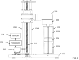
- FIG. 2 depicts the texture analyzer of FIGs. 1A and 1B with the exterior housing removed.
- a fixture 202 is positioned between the load cell module 108 and the base plate 102 and is designed to facilitate a particular test of a particular product type.
- the fixture 202 may include a sample support 202A positioned on the base plate 202 and/or an end effector 202B positioned on the load cell module.
- a sample 204 is positioned within the fixture 202 relative to the base plate 102 and the load cell module 108 received by the moveable carriage 106.
- the moveable carriage 106 then provides controlled tensile and/or compressive loads to the sample 204 through the load cell module 108 received by the carriage 106 with the appropriate fixture 202 in place and signals are read from the load cell module for use in determining sample characteristics.
- Tensile and compressive loads can be measured for a variety of test types by controlling the position, speed of motion and/or the applied load.
- a processor 206 controls the tensile and compressive loads to administer tests on the sample 204 and processes readings from the load cell module 108 to characterize the sample.
- the processor 206 may display results on display 110 ( FIG. 1A ). Additionally, processor 206 is in communication with memory 208 to retrieve by way of non-limiting example, test parameter information and deflection information for (1) the support structure and (2) the inserted load cell module.
- the carriage support includes a first vertical rod 104A and a second vertical rod 104B on which the moveable carriage 106 rides.
- a motor 210 turns a screw 212 that raises and lowers the moveable carriage 106 to apply tensile and compressive forces.
- Some of the unique aspects of the texture analyzer relate to (i.) compensating for deflection of the support structure and for deflection of the particular load cell module received by the support structure, (ii.) applying an adjustable single tap infinite impulse response (IIR) filter to limit signal noise in the raw load signal from the load cell module, and (iii.) characterizing an aspect of the sample (e.g., compliance of the sample in mm/Kg) prior to analysis and/or during analysis in real time) for use in controlling the load applied to the sample.
- IIR infinite impulse response
- known texture analyzers compensate for deflection of the combined support structure and load cell module. It is not known to compensate for deflection of the load cell module itself. Since the load cell modules can be replaced with load cell module of a different type, and each type of load cell module has its own deflection characteristics, superior measurement results can be obtained by compensating for deflection of both the support structure and the specific load cell module received by the carriage of the texture analyzer.
- FIG. 3 depicts electronic components and processing modules for the texture analyzer of FIG. 1A .
- the system includes three circuit boards/control modules. These modules are (1.) a load cell module, (2.) a real-time processing module, and (3.) a computer module.
- the load cell module integrates a commercial load cell so it can be calibrated and utilize high-speed digital communications with the real time module.
- the carriage supports the load cell module and provides an electrical connection.
- the real time module controls the carriage motion and can adjust the position according to the high-speed load cell data it receives.
- the computer module provides overall control of the motions and measurements to perform test sequences and provide user and system external interfaces. The detailed system block diagram is shown in FIG. 4 .
- Total deflection Load Cell Deflection + Structural Deflection
- Load Cell Deflection is calibrated as deflection in mm, according to the full scale load [ L FS ] of the load cell.
- the calibration can be linear, or another function depending on the actual behavior of the load cell:
- Load Cell deflection D LC ⁇ Load gm / L FS gm
- the compensation can include a term that compensates for changes in system compliance as the carriage moves vertically, and as the temperature changes from temperature at calibration. Temperature compensation may also be useful for the load cell module.
- an adjustable single tap IIR filter is applied to help limit signal noise in the raw load signal from the load cell module.
- the filter is adjustable depending on the test parameters to enable recognition of trends in the load data. Additionally, the filter sensitivity is adjustable to measure brittle, high frequency events. Variable filtering allows the maximum usability of the product, to provide useful measurements over the widest possible range of behaviors at a peak data rate (e.g., 500 Hz).
- One "single tap” IIR filter is applied, to help limit the signal noise in the raw load signal. Depending on the test parameters, it may be necessary to adjust the filter to be able to recognize the important trends in the load data. Likewise, for measurements of brittle, high frequency events, the ability to adjust the filter sensitivity is important. Variable filtering allows the maximum usability of the product, to provide useful measurements over the widest possible range of behaviors at the peak data rate [500 Hz].
- the mechanical system produces accurate movements for the full range of loads.
- a set of bushings are configured to adjust to the positions of the rods and eliminate backlash in the linear bearings. The result is a rigid constraint that allows free vertical travel of the carriage without chatter or motion errors.
- the texture analyzer 100 and its associated software are configured to characterize the sample and apply the characterization to the control of load.
- texture analyzer 100 Due to the wide variety of stiffness in samples, it is difficult to maintain a specific load and/or to control the motion of the load cell module as the sample deflects. When pushing against a very hard sample it is very difficult to stabilize the system.
- Known texture analyzers set a middle range value for the feed forward.
- the texture analyzer 100 and its associated software characterize the sample during the test (e.g., compliance of the sample in mm/Kg) and apply the characterization to control algorithms for applying the load to the sample.
- FIG. 5 depicts example steps for analyzing a sample with a texture analyzer.
- step 502 insert a load cell module into a moveable carriage of a texture analyzer support structure.
- step 504 identify the inserted load cell module.
- step 506 retrieve from a memory the texture analyzer support structure deflection parameters and one of a plurality of load cell module deflection parameters stored in a memory of the texture analyzer corresponding to the identified load cell module.
- step 508 position a sample relative to a base plate and the inserted load cell module.
- step 510 apply at least one of tensile loads or compressive loads to the sample through the load cell module.
- step 512 obtain raw measurement signals from the load cell module.
- step 514 refine the raw measurement signals to compensate for deflection in the load cell module using the retrieved one of the plurality of load cell module deflection parameters and to compensate for deflection in the texture analyzer support structure using the retrieved support structure deflection parameters.
- FIG. 6A is a graphical user interface (GUI) for selecting an adjustment type.
- GUI graphical user interface
- a user may select the type by first pressing one of "Manual Adjust,” “Auto Adjust,” “Upper Limit,” or “Lower Limit” (which highlights the type of adjustment desired) and, then pressing "Select.”
- the Manual Adjust is selected, the Manual Adjustment GUI ( FIG. 6B ) is displayed.
- “Manual Adjust” is associated with the actual location of the beam.
- Auto Adjust is associated with the standard location of the beam for most test set ups (e.g., the test start position).
- “Upper Limit” is associated with the upper limit of the travel distance as set by the user (an error may be shown if the beak goes above this setting).
- “Lower Limit” is associated with the lower limit of the travel distance as set by the user (an error may be shown if the beak goes below this setting.
- the GUIs of FIG. 6A and 6B may be displayed on display 110 of the texture analyzer 100.
- pressing the up or down arrows causes the beam to move 1mm. If you press and hold one of the arrows for at least 1.5 seconds, it will start moving the beam faster, up to 10mm/s. The AUTO key will move the beam at 10mm/s to the desired location.
- the SET MANUAL ADJ. screen is shown upon pressing the ADJUST BEAM key by default. Pressing SET will return you to the ADJUST BEAM screen where the limits and auto value can be set.
- Pressing BACK from either the SET MANUAL ADJUST screen or the ADJUST BEAM screen will return the user to the previous screen accessed. This would usually be a CONFIGURE TEST screen or possibly a RESULT screen, but could be MAIN, SETTINGS or SERVICE as well.
- the GUI adjustment system enables the operator to set the values on the GUI, and the processor tracks the position to move between these "virtual" stops. This is unlike convention texture analyzers in which mechanical switches and actuators on the device are set by hand.
- a GUI may also be presented on display 110 that displays a "virtual scale,” which shows the relative position of the carriage, and can display the position of limits of travel set by a user.
- the scale may be displayed adjacent to the other key information describing tests set-ups and the progress of tests as they are running.
- inventive subject matter has been described with reference to specific example embodiments, various modifications and changes may be made to these embodiments without departing from the broader scope of embodiments of the present disclosure.
- inventive subject matter may be referred to herein, individually or collectively, by the term "invention" merely for convenience and without intending to voluntarily limit the scope of this application to any single disclosure or inventive concept if more than one is, in fact, disclosed.
Landscapes
- Physics & Mathematics (AREA)
- General Physics & Mathematics (AREA)
- Engineering & Computer Science (AREA)
- Food Science & Technology (AREA)
- Health & Medical Sciences (AREA)
- Life Sciences & Earth Sciences (AREA)
- Chemical & Material Sciences (AREA)
- Medicinal Chemistry (AREA)
- Analytical Chemistry (AREA)
- Biochemistry (AREA)
- General Health & Medical Sciences (AREA)
- Immunology (AREA)
- Pathology (AREA)
- Investigating Strength Of Materials By Application Of Mechanical Stress (AREA)
- Automatic Analysis And Handling Materials Therefor (AREA)
Description
- Texture analysis concerns the measurement of the mechanical properties of a product, often a food product, as they relate to its sensory properties detected by humans. Fifty years of texture research has developed a set of definitions relating the sensory properties of a product to the instrumental properties which can be calculated from the results of a two cycle texture profile analysis test. Texture analyzers perform these test by applying controlled forces to the product and recording the product's response in the form of force, deformation, and time.
US 2018/209882 A1 for example describes a mechanical device that measures physical parameters such as compression strength, elasticity, firmness, deformation resistance and the like, on one or a plurality of compressible test objects including fruits, nuts and vegetables, and which operates in a semi-automatic fashion using an indexable turntable linked to one or a plurality of measuring stations capable of independently measuring said physical parameters.
The publication by L.S Stephens ET AL "Mechanical property evaluation and failure analysis of cantilevered LIGA nickel microposts", Journal of Microelectromechanical Systems, doi: 10.1109/84.946780, (200109), pages 347 - 359, describes an apparatus built to measure the elastic modulus and bending strength (modulus of rupture) of LIGA nickel posts. The apparatus uses the static cantilever beam bending approach to measure mechanical properties in a direction parallel to the growth direction. - The invention is best understood from the following detailed description when read in connection with the accompanying drawings, with like elements having the same reference numerals. When a plurality of similar elements are present, a single reference numeral may be assigned to the plurality of similar elements with a small letter designation referring to specific elements. When referring to the elements collectively or to a non-specific one or more of the elements, the small letter designation may be dropped. This emphasizes that according to common practice, the various features of the drawings are not drawn to scale unless otherwise indicated. On the contrary, the dimensions of the various features may be expanded or reduced for clarity. Included in the drawings are the following figures:
-
FIG. 1A is a perspective view of a texture analyzer; -
FIG. 1B is a side view of the texture analyzer ofFIG. 1A and a load cell for insertion in the texture analyzer; -
FIG. 2 is a side view of the texture analyzer ofFIG. 1A and 1B with the exterior housing removed, the load cell inserted, and a dashed representation of where a fixture and a sample are positioned in order to analyze the sample; -
FIG. 3 is a block diagram of electronic components and processing modules for the texture analyzer ofFIG. 1A ; -
FIG. 4 is a detailed block diagram of the components inFIG. 3 ; -
FIG. 5 is a flow chart depicting example steps; -
FIG. 6A is a graphical user interface for selecting an adjustment type; and -
FIG. 6B is a graphical user interface for manual adjustment. - In the following detailed description, numerous specific details are set forth by way of examples in order to provide a thorough understanding of the relevant teachings. However, it should be apparent to those skilled in the art that the present teachings may be practiced without such details. In other instances, description of well-known methods, procedures, components, and circuitry are set forth at a relatively high-level, without detail, in order to avoid unnecessarily obscuring aspects of the present teachings.
- This description of the exemplary embodiments that follows is intended to be read in connection with the accompanying drawings, which are to be considered part of the entire written description. In the description, relative terms such as "lower," "upper," "horizontal," "vertical,", "above," "below," "up," "down," "top" and "bottom" as well as derivative thereof (e.g., "horizontally," "downwardly," "upwardly," etc.) should be construed to refer to the orientation as then described or as shown in the drawing under discussion. These relative terms are for convenience of description and do not require that the apparatus be constructed or operated in a particular orientation. Terms concerning attachments, coupling and the like, such as "connected" and "interconnected," refer to a relationship wherein structures are secured or attached to one another either directly or indirectly through intervening structures, as well as both removable or rigid attachments or relationships, unless expressly described otherwise.
- The term "on" means directly supported by an element or indirectly supported by the element through another element integrated into or supported by the element.
- Additional objects, advantages and novel features of the examples will be set forth in part in the following description, and in part will become apparent to those skilled in the art upon examination of the following and the accompanying drawings or they may learn by production or operation of the examples. The methodologies, instrumentalities and combinations particularly pointed out in the appended claims assist in realizing and ascertaining the objects and advantages of the present subject matter.
-
FIGs. 1A and 1B depict a perspective view and a side view, respectively, of atexture analyzer 100. Thetexture analyzer 100 includes include a support structure having abase plate 102, acarriage support 104, and amoveable carriage 106. The moveable carriage is adapted to receive a replaceableload cell modules 108 and to move the receiveload cell module 108 relative to thebase plate 102. Theload cell modules 108 can be selected based on the product sample being tested and the type of test being performed on the product sample. Eachload cell module 108 has its own deflection characteristics that are unique to that load cell module. These deflection characteristics are determined using a load analyzer and stored for later use. - The
texture analyzer 100 includes adisplay 110 for displaying information such as set up information and test measurements. Thetexture analyzer 100 additionally includesuser controls 112 for setting up and adjusting thetexture analyzer 100. -
FIG. 2 depicts the texture analyzer ofFIGs. 1A and 1B with the exterior housing removed. Afixture 202 is positioned between theload cell module 108 and thebase plate 102 and is designed to facilitate a particular test of a particular product type. Thefixture 202 may include asample support 202A positioned on thebase plate 202 and/or anend effector 202B positioned on the load cell module. - In use, a
sample 204 is positioned within thefixture 202 relative to thebase plate 102 and theload cell module 108 received by themoveable carriage 106. Themoveable carriage 106 then provides controlled tensile and/or compressive loads to thesample 204 through theload cell module 108 received by thecarriage 106 with theappropriate fixture 202 in place and signals are read from the load cell module for use in determining sample characteristics. Tensile and compressive loads can be measured for a variety of test types by controlling the position, speed of motion and/or the applied load. - A
processor 206 controls the tensile and compressive loads to administer tests on thesample 204 and processes readings from theload cell module 108 to characterize the sample. Theprocessor 206 may display results on display 110 (FIG. 1A ). Additionally,processor 206 is in communication withmemory 208 to retrieve by way of non-limiting example, test parameter information and deflection information for (1) the support structure and (2) the inserted load cell module. - As shown in
FIG. 2 , the carriage support includes a firstvertical rod 104A and a secondvertical rod 104B on which themoveable carriage 106 rides. Amotor 210 turns ascrew 212 that raises and lowers themoveable carriage 106 to apply tensile and compressive forces. - Some of the unique aspects of the texture analyzer relate to (i.) compensating for deflection of the support structure and for deflection of the particular load cell module received by the support structure, (ii.) applying an adjustable single tap infinite impulse response (IIR) filter to limit signal noise in the raw load signal from the load cell module, and (iii.) characterizing an aspect of the sample (e.g., compliance of the sample in mm/Kg) prior to analysis and/or during analysis in real time) for use in controlling the load applied to the sample.
- Regarding (i.), known texture analyzers compensate for deflection of the combined support structure and load cell module. It is not known to compensate for deflection of the load cell module itself. Since the load cell modules can be replaced with load cell module of a different type, and each type of load cell module has its own deflection characteristics, superior measurement results can be obtained by compensating for deflection of both the support structure and the specific load cell module received by the carriage of the texture analyzer.
-
FIG. 3 depicts electronic components and processing modules for the texture analyzer ofFIG. 1A . The system includes three circuit boards/control modules. These modules are (1.) a load cell module, (2.) a real-time processing module, and (3.) a computer module. - The load cell module integrates a commercial load cell so it can be calibrated and utilize high-speed digital communications with the real time module. The carriage supports the load cell module and provides an electrical connection. The real time module controls the carriage motion and can adjust the position according to the high-speed load cell data it receives. The computer module provides overall control of the motions and measurements to perform test sequences and provide user and system external interfaces. The detailed system block diagram is shown in
FIG. 4 . - Deflection compensation:

- Load Cell Deflection is calibrated as deflection in mm, according to the full scale load [LFS ] of the load cell. The calibration can be linear, or another function depending on the actual behavior of the load cell:

- Load = the actual applied load
- LFS = the full scale load of the load cell
- DLC= load cell deflection calibration coefficient. For a typical load cell, the linear model is very accurate, DLC is typically 0.2 mm
- Structural deflection is calibrated with a polynomial, using coefficients based on the maximum design load for the structure [Lmax, e.g. 100 kg]
- For convenience, the load and Lmax are in kg. The 3rd order polynomial has the form:

- Higher order polynomials are possible, likewise alternate equations for fitting. The critical elements is that the equations can be readily implemented in the LCM/RTM and the superposition of the two deflections can be calculated at high speed to enable accurate control of position.
- As the carriage is moved, changes in the applied load cause a deflection in the system. This results in the motor commanded move not matching the actual end-effector motion; the load produced by the sample under test has caused a change in actual position opposite to the load change. The difference in theoretical position and actual position is corrected by commanding an incremental additional motion based on the equation above. The position correction is made multiple times during the execution of a move command.
- The compensation can include a term that compensates for changes in system compliance as the carriage moves vertically, and as the temperature changes from temperature at calibration. Temperature compensation may also be useful for the load cell module.
- Regarding (ii.), an adjustable single tap IIR filter is applied to help limit signal noise in the raw load signal from the load cell module. The filter is adjustable depending on the test parameters to enable recognition of trends in the load data. Additionally, the filter sensitivity is adjustable to measure brittle, high frequency events. Variable filtering allows the maximum usability of the product, to provide useful measurements over the widest possible range of behaviors at a peak data rate (e.g., 500 Hz).
- One "single tap" IIR filter is applied, to help limit the signal noise in the raw load signal. Depending on the test parameters, it may be necessary to adjust the filter to be able to recognize the important trends in the load data. Likewise, for measurements of brittle, high frequency events, the ability to adjust the filter sensitivity is important. Variable filtering allows the maximum usability of the product, to provide useful measurements over the widest possible range of behaviors at the peak data rate [500 Hz]. An example filtering algorithm follows:

- Xn filtered = filtered value, reported for step n
- Were b = filter parameter; Xn = measurement at step n; and X(n-1)filtered = previous filtered measurement step
- This allows a single parameter, b, to adjust the influence of the previous measuring point in the weighted average with the current point. Typical values are 0.5 < b < 1.0. b = 0.0 is the trivial case, eliminating any contribution from the previous point, so no filtering is done.
- The mechanical system produces accurate movements for the full range of loads. In additional to the pair of
vertical rods - For some tests, it is desirable to control the applied load, and adjust the position of the force transducer (i.e., the load cell module 108) to maintain the desired load as the
sample 204 deforms over time. Thetexture analyzer 100 and its associated software are configured to characterize the sample and apply the characterization to the control of load. - Due to the wide variety of stiffness in samples, it is difficult to maintain a specific load and/or to control the motion of the load cell module as the sample deflects. When pushing against a very hard sample it is very difficult to stabilize the system. Known texture analyzers set a middle range value for the feed forward. In
texture analyzer 100, thetexture analyzer 100 and its associated software characterize the sample during the test (e.g., compliance of the sample in mm/Kg) and apply the characterization to control algorithms for applying the load to the sample. - The following algorithm compares the actual load to a desired load and corrects the position to maintain the load for a test interval. This is analogous to applying a fixed load e.g. with a dead weight and measuring the deflection over time to characterize time-based behavior like creep. For stable control of the system, the speed for position corrections is based upon the compliance of the material. The characterization of material can be done with a calibration sample or real time during a test.

- Where Csample = sample compliance [mm/Kg] and TCmachine = time constant for system.
- Good results are achieved for a wide variety of sample materials by determining the sample compliance at Loadtarget.
-
FIG. 5 depicts example steps for analyzing a sample with a texture analyzer. - At
step 502, insert a load cell module into a moveable carriage of a texture analyzer support structure. - At
step 504, identify the inserted load cell module. - At
step 506, retrieve from a memory the texture analyzer support structure deflection parameters and one of a plurality of load cell module deflection parameters stored in a memory of the texture analyzer corresponding to the identified load cell module. - At
step 508, position a sample relative to a base plate and the inserted load cell module. - At
step 510, apply at least one of tensile loads or compressive loads to the sample through the load cell module. - At
step 512, obtain raw measurement signals from the load cell module. - At
step 514, refine the raw measurement signals to compensate for deflection in the load cell module using the retrieved one of the plurality of load cell module deflection parameters and to compensate for deflection in the texture analyzer support structure using the retrieved support structure deflection parameters. -
FIG. 6A is a graphical user interface (GUI) for selecting an adjustment type. A user may select the type by first pressing one of "Manual Adjust," "Auto Adjust," "Upper Limit," or "Lower Limit" (which highlights the type of adjustment desired) and, then pressing "Select." If the Manual Adjust is selected, the Manual Adjustment GUI (FIG. 6B ) is displayed. "Manual Adjust" is associated with the actual location of the beam. "Auto Adjust" is associated with the standard location of the beam for most test set ups (e.g., the test start position). "Upper Limit" is associated with the upper limit of the travel distance as set by the user (an error may be shown if the beak goes above this setting). "Lower Limit" is associated with the lower limit of the travel distance as set by the user (an error may be shown if the beak goes below this setting. The GUIs ofFIG. 6A and 6B may be displayed ondisplay 110 of thetexture analyzer 100. - In an example, pressing the up or down arrows causes the beam to move 1mm. If you press and hold one of the arrows for at least 1.5 seconds, it will start moving the beam faster, up to 10mm/s. The AUTO key will move the beam at 10mm/s to the desired location.
- While on the SET MANUAL ADJ. screen, pressing the up or down arrows will cause the beam to actually move along with the value within the UPPER LIMIT and LOWER LIMIT settings only.
- The SET MANUAL ADJ. screen is shown upon pressing the ADJUST BEAM key by default. Pressing SET will return you to the ADJUST BEAM screen where the limits and auto value can be set.
- Pressing AUTO will move the beam to the location specified in AUTO ADJUST. If the location is outside the UPPER/LOWER LIMIT, a TRAVEL ERROR is shown.
- Pressing BACK from either the SET MANUAL ADJUST screen or the ADJUST BEAM screen will return the user to the previous screen accessed. This would usually be a CONFIGURE TEST screen or possibly a RESULT screen, but could be MAIN, SETTINGS or SERVICE as well.
- The GUI adjustment system enables the operator to set the values on the GUI, and the processor tracks the position to move between these "virtual" stops. This is unlike convention texture analyzers in which mechanical switches and actuators on the device are set by hand.
- A GUI may also be presented on
display 110 that displays a "virtual scale," which shows the relative position of the carriage, and can display the position of limits of travel set by a user. The scale may be displayed adjacent to the other key information describing tests set-ups and the progress of tests as they are running. - The terms and expressions used herein are understood to have the ordinary meaning as is accorded to such terms and expressions with respect to their corresponding respective areas of inquiry and study except where specific meanings have otherwise been set forth herein. Relational terms such as first and second and the like may be used solely to distinguish one entity or action from another without necessarily requiring or implying any actual such relationship or order between such entities or actions. The terms "comprises," "comprising," "includes," "including," or any other variation thereof, are intended to cover a non-exclusive inclusion, such that a process, method, article, or apparatus that comprises or includes a list of elements or steps does not include only those elements or steps but may include other elements or steps not expressly listed or inherent to such process, method, article, or apparatus. An element preceded by "a" or "an" does not, without further constraints, preclude the existence of additional identical elements in the process, method, article, or apparatus that comprises the element.
- In addition, in the foregoing Detailed Description, it can be seen that various features are grouped together in various examples for the purpose of streamlining the disclosure. This method of disclosure is not to be interpreted as reflecting an intention that the claimed examples require more features than are expressly recited in each claim. The protection is limited only by the attached claims.
- Although an overview of the inventive subject matter has been described with reference to specific example embodiments, various modifications and changes may be made to these embodiments without departing from the broader scope of embodiments of the present disclosure. Such embodiments of the inventive subject matter may be referred to herein, individually or collectively, by the term "invention" merely for convenience and without intending to voluntarily limit the scope of this application to any single disclosure or inventive concept if more than one is, in fact, disclosed.
- The embodiments illustrated herein are described in sufficient detail to enable those skilled in the art to practice the teachings disclosed. Other embodiments may be used and derived therefrom, such that structural and logical substitutions and changes may be made without departing from the scope of this disclosure. The Detailed Description, therefore, is not to be taken in a limiting sense, and the scope of various embodiments is defined only by the appended claims.
Claims (10)
- A texture analyzer (100) comprising:a support structure including a base plate (102), a carriage support (104) extending from the base plate (102), and a moveable carriage (106) coupled to the carriage support (104) for movement relative to the base plate (102), the moveable carriage (106) configured to receive a load cell module (108);a fixture positioned between the base plate (102) and the load cell module (108), the fixture configured to receive a sample for analysis by the texture analyzer;a memory (208) storing support structure deflection parameters and a plurality of load cell module (108) deflection parameters; and characterised in that it comprises:
a processor (206) coupled to the memory (208), the support structure, and the load cell module (108) when received by the moveable carriage (106), the processor (206) configured to perform functions including functions to:identify the load cell module (108) when received by the moveable carriage (106);retrieve from the memory (208) the support structure deflection parameters and one of the plurality of load cell module (108) deflection parameters corresponding to the identified load cell module (108);obtain raw measurement signals from the load cell module (108) when received by the moveable carriage (106); andrefine the raw measurement signals to compensate for deflection in the load cell module (108) using the retrieved one of the plurality of load cell module (108) deflection parameters and to compensate for deflection in the support structure using the retrieved support structure deflection parameters. - The texture analyzer of claim 1, wherein the fixture includes at least one of a sample support adjacent the base plate (102) or an effector adjacent the load cell module (108) when received by the moveable carriage (106).
- The texture analyzer of claim 1, where the processor (206) is further configured to perform a function to:
apply an adjustable single tap infinite impulse response (IIR) filter to limit signal noise in the raw measurement signals from the load cell module (108). - The texture analyzer of claim 1, where the processor (206) is further configured to perform a function to:move the moveable carriage (106) to apply at least one of compressive or tensile forces to the sample though the load cell module (108);characterize the sample from the refined measurement signals; andadjust the movement of the moveable carriage (106) responsive to the characterization of the sample.
- The texture analyzer of claim 1, further comprising a user interface (110, 112) coupled to the processor (206) to receive user inputs for setting at least one limit on travel of the moveable carriage (106), wherein the processor (206) monitors the moveable carriage (106) relative to the set at least one limit.
- The texture analyzer of claim 5, wherein the user interface displays a virtual scale showing relative position the moveable carriage (106).
- A method for analyzing a sample, the method comprising the steps of:inserting a load cell module (108) into a moveable carriage (106) of a texture analyzer support structure;the method characterised in that it comprises:identifying the inserted load cell module (108);retrieving from a memory (208) the texture analyzer support structure deflection parameters and one of a plurality of load cell module (108) deflection parameters stored in a memory (208) of the texture analyzer corresponding to the identified load cell module (108);positioning a sample relative to a base plate (102) and the inserted load cell module (108);applying at least one of tensile loads or compressive loads to the sample through the load cell module (108);obtaining raw measurement signals from the load cell module (108);refining the raw measurement signals to compensate for deflection in the load cell module (108) using the retrieved one of the plurality of load cell module (108) deflection parameters and to compensate for deflection in the texture analyzer support structure using the retrieved support structure deflection parameters.
- The method of claim 7, wherein the positioning steps comprises positioning the sample within a fixture including at least one of a sample support adjacent the base plate (102) or an effector adjacent the load cell module (108).
- The method of claim 7, wherein the refining step further comprises the step of:
applying an adjustable single tap infinite impulse response (IIR) filter to limit signal noise in the raw measurement signals from the load cell module (108). - The method of claim 7, wherein the applying step comprises the steps of:moving the moveable carriage (106) to apply at least one of compressive or tensile forces to the sample though the load cell module (108);characterizing the sample from the refined measurement signals; andadjusting the movement of the moveable carriage (106) responsive to the characterization of the sample.
Applications Claiming Priority (3)
| Application Number | Priority Date | Filing Date | Title |
|---|---|---|---|
| US201862782878P | 2018-12-20 | 2018-12-20 | |
| US16/715,336 US11293743B2 (en) | 2018-12-20 | 2019-12-16 | Texture analyzer |
| PCT/US2019/067522 WO2020132270A1 (en) | 2018-12-20 | 2019-12-19 | Texture analyzer |
Publications (2)
| Publication Number | Publication Date |
|---|---|
| EP3899528A1 EP3899528A1 (en) | 2021-10-27 |
| EP3899528B1 true EP3899528B1 (en) | 2024-03-27 |
Family
ID=71098142
Family Applications (1)
| Application Number | Title | Priority Date | Filing Date |
|---|---|---|---|
| EP19842667.8A Active EP3899528B1 (en) | 2018-12-20 | 2019-12-19 | Texture analyzer |
Country Status (9)
| Country | Link |
|---|---|
| US (1) | US11293743B2 (en) |
| EP (1) | EP3899528B1 (en) |
| DK (1) | DK3899528T3 (en) |
| ES (1) | ES2981663T3 (en) |
| FI (1) | FI3899528T3 (en) |
| HU (1) | HUE066949T2 (en) |
| PL (1) | PL3899528T3 (en) |
| PT (1) | PT3899528T (en) |
| WO (1) | WO2020132270A1 (en) |
Families Citing this family (1)
| Publication number | Priority date | Publication date | Assignee | Title |
|---|---|---|---|---|
| WO2026096498A1 (en) * | 2024-10-31 | 2026-05-07 | Illinois Tool Works Inc. | Actuator-based testing systems data communication |
Family Cites Families (25)
| Publication number | Priority date | Publication date | Assignee | Title |
|---|---|---|---|---|
| DE3543906A1 (en) * | 1985-12-12 | 1987-06-25 | Hommelwerke Gmbh | DEVICE FOR MEASURING THE DESIGN OF A SURFACE ALONG A SCAN LINE |
| US6077822A (en) | 1993-09-14 | 2000-06-20 | Dumex-Alpharma A/S | Drug salts |
| US5629489A (en) | 1995-02-06 | 1997-05-13 | Weigh-Tronix, Inc. | Load cell assembly with linearization and common mode discrimination of complementary force-responsive signals |
| US6508132B1 (en) | 1999-02-17 | 2003-01-21 | Instron Corporation | Dynamic load cell apparatus |
| JP4164682B2 (en) | 2004-05-18 | 2008-10-15 | 株式会社島津製作所 | Material testing machine |
| JP4958754B2 (en) | 2007-12-07 | 2012-06-20 | 株式会社ミツトヨ | Hardness tester and calibration method for hardness tester |
| JP5265976B2 (en) * | 2008-07-01 | 2013-08-14 | 株式会社ミツトヨ | Measuring machine |
| EP2334254B1 (en) * | 2008-09-30 | 2018-03-28 | American Dental Association | Apparatus and methods for testing the polishability of materials |
| DE102008050465B4 (en) | 2008-10-08 | 2012-12-13 | Zwick Gmbh & Co. Kg | Device for performing component and material tests on samples |
| JP5051099B2 (en) | 2008-11-04 | 2012-10-17 | 株式会社島津製作所 | Material testing machine |
| US8151638B2 (en) | 2008-12-07 | 2012-04-10 | Robert Bosch Gmbh | Spring force component tester |
| JP5098995B2 (en) | 2008-12-19 | 2012-12-12 | 株式会社島津製作所 | Sensor characteristic correction device and material testing machine |
| JP5369944B2 (en) | 2009-07-07 | 2013-12-18 | 株式会社島津製作所 | Digital filter and material testing machine |
| JP5724161B2 (en) | 2009-08-19 | 2015-05-27 | 株式会社島津製作所 | Material testing machine |
| JP5823306B2 (en) * | 2011-03-18 | 2015-11-25 | 株式会社ミツトヨ | Calibration method of surface texture measuring machine |
| WO2013038837A1 (en) | 2011-09-14 | 2013-03-21 | スチールプランテック株式会社 | Roller leveler and method for leveling plate using same |
| DE112012006115B4 (en) * | 2012-01-04 | 2016-03-03 | Tokyo Seimitsu Co.,Ltd. | Contour and Surface Texture Meter and Contour and Surface Texture Measurement |
| JP5958392B2 (en) | 2013-03-15 | 2016-08-02 | 株式会社島津製作所 | Noise reduction device for time series measurement signals |
| JP6047045B2 (en) * | 2013-03-25 | 2016-12-21 | 株式会社ミツトヨ | Contour measuring machine |
| UA90314U (en) | 2013-11-05 | 2014-05-26 | Ольга Миколайовна Шаніна | Semiautomatic texturometer for the determination of structural-mechanical properties of food products |
| JP6245183B2 (en) | 2015-01-14 | 2017-12-13 | 株式会社島津製作所 | Analog signal processing circuit, physical quantity measuring device and material testing machine |
| JP6658383B2 (en) | 2016-07-27 | 2020-03-04 | 株式会社島津製作所 | Material testing machine |
| US10429283B2 (en) | 2017-01-20 | 2019-10-01 | Creative Viewpoint Machinery | Fruit testing device |
| JP6780522B2 (en) | 2017-01-31 | 2020-11-04 | 株式会社島津製作所 | Material testing machine |
| JP6842061B2 (en) * | 2017-02-10 | 2021-03-17 | 国立大学法人神戸大学 | Evaluation method of object surface, evaluation device, machining method of workpiece using the evaluation method, and machine tool |
-
2019
- 2019-12-16 US US16/715,336 patent/US11293743B2/en active Active
- 2019-12-19 ES ES19842667T patent/ES2981663T3/en active Active
- 2019-12-19 DK DK19842667.8T patent/DK3899528T3/en active
- 2019-12-19 PL PL19842667.8T patent/PL3899528T3/en unknown
- 2019-12-19 EP EP19842667.8A patent/EP3899528B1/en active Active
- 2019-12-19 FI FIEP19842667.8T patent/FI3899528T3/en active
- 2019-12-19 WO PCT/US2019/067522 patent/WO2020132270A1/en not_active Ceased
- 2019-12-19 HU HUE19842667A patent/HUE066949T2/en unknown
- 2019-12-19 PT PT198426678T patent/PT3899528T/en unknown
Also Published As
| Publication number | Publication date |
|---|---|
| HUE066949T2 (en) | 2024-09-28 |
| PT3899528T (en) | 2024-06-28 |
| ES2981663T3 (en) | 2024-10-09 |
| EP3899528A1 (en) | 2021-10-27 |
| US20200200521A1 (en) | 2020-06-25 |
| PL3899528T3 (en) | 2024-07-29 |
| WO2020132270A1 (en) | 2020-06-25 |
| DK3899528T3 (en) | 2024-07-01 |
| US11293743B2 (en) | 2022-04-05 |
| FI3899528T3 (en) | 2024-06-28 |
Similar Documents
| Publication | Publication Date | Title |
|---|---|---|
| EP1736745B1 (en) | Method for adaptively correcting drift conditions in a force measuring device and force measuring device for carrying out the method. | |
| CA2059545C (en) | Method of and an apparatus for sectioning a specimen | |
| US20020029621A1 (en) | Instrument for high throughput measurement of material physical properties and method of using same | |
| US9904258B2 (en) | Testing machine with graphical user interface with situational awareness | |
| EP2860501B1 (en) | Weighing cell with a device for correcting eccentric load errors and method for correcting eccentric load errors | |
| AT515219A4 (en) | Method for determination of measured data of samples and rheometers | |
| Trombetti et al. | Shaking table dynamics: results from a test-analysis comparison study | |
| EP3440447B1 (en) | Compensated mechanical testing system | |
| CN119738614A (en) | Accurate low-resistance-based equipotential connection measurement method and system | |
| US5517860A (en) | Film testing | |
| US11293743B2 (en) | Texture analyzer | |
| EP3489653B1 (en) | System and method for testing a material system | |
| CN114397103A (en) | Vehicle door operation comfort evaluation rack and method | |
| EP0921388B1 (en) | Viscoelasticity measurement apparatus | |
| US8511172B2 (en) | Sheet metal stretch-bend-draw simulator apparatus and method | |
| CN211013057U (en) | Detection equipment for proportional servo valve | |
| KR101670760B1 (en) | Apparatus for Indentation Test | |
| CN119175669A (en) | AI-based vehicle clamp positioning system | |
| DE4309530C2 (en) | Device for the dynamic mechanical analysis of test specimens | |
| CN117110064A (en) | An electronic pressure measuring device | |
| Voisey et al. | A system for recording deformations in texture tests | |
| CN223684215U (en) | Sheet metal rolling assembly calibration equipment | |
| CN116718640B (en) | Performance degradation testing method for macrofiber piezoelectric composite material | |
| EP4124821B1 (en) | Coordinate measuring device and method for temperature-dependent correction of dimensional measurement data | |
| CN216771051U (en) | Hinge car door test bench |
Legal Events
| Date | Code | Title | Description |
|---|---|---|---|
| STAA | Information on the status of an ep patent application or granted ep patent |
Free format text: STATUS: UNKNOWN |
|
| STAA | Information on the status of an ep patent application or granted ep patent |
Free format text: STATUS: THE INTERNATIONAL PUBLICATION HAS BEEN MADE |
|
| PUAI | Public reference made under article 153(3) epc to a published international application that has entered the european phase |
Free format text: ORIGINAL CODE: 0009012 |
|
| STAA | Information on the status of an ep patent application or granted ep patent |
Free format text: STATUS: REQUEST FOR EXAMINATION WAS MADE |
|
| 17P | Request for examination filed |
Effective date: 20210719 |
|
| AK | Designated contracting states |
Kind code of ref document: A1 Designated state(s): AL AT BE BG CH CY CZ DE DK EE ES FI FR GB GR HR HU IE IS IT LI LT LU LV MC MK MT NL NO PL PT RO RS SE SI SK SM TR |
|
| DAV | Request for validation of the european patent (deleted) | ||
| DAX | Request for extension of the european patent (deleted) | ||
| P01 | Opt-out of the competence of the unified patent court (upc) registered |
Effective date: 20230615 |
|
| GRAP | Despatch of communication of intention to grant a patent |
Free format text: ORIGINAL CODE: EPIDOSNIGR1 |
|
| STAA | Information on the status of an ep patent application or granted ep patent |
Free format text: STATUS: GRANT OF PATENT IS INTENDED |
|
| INTG | Intention to grant announced |
Effective date: 20231017 |
|
| GRAS | Grant fee paid |
Free format text: ORIGINAL CODE: EPIDOSNIGR3 |
|
| GRAA | (expected) grant |
Free format text: ORIGINAL CODE: 0009210 |
|
| STAA | Information on the status of an ep patent application or granted ep patent |
Free format text: STATUS: THE PATENT HAS BEEN GRANTED |
|
| AK | Designated contracting states |
Kind code of ref document: B1 Designated state(s): AL AT BE BG CH CY CZ DE DK EE ES FI FR GB GR HR HU IE IS IT LI LT LU LV MC MK MT NL NO PL PT RO RS SE SI SK SM TR |
|
| REG | Reference to a national code |
Ref country code: GB Ref legal event code: FG4D |
|
| REG | Reference to a national code |
Ref country code: CH Ref legal event code: EP |
|
| REG | Reference to a national code |
Ref country code: DE Ref legal event code: R096 Ref document number: 602019049172 Country of ref document: DE |
|
| REG | Reference to a national code |
Ref country code: IE Ref legal event code: FG4D |
|
| REG | Reference to a national code |
Ref country code: FI Ref legal event code: FGE Ref country code: PT Ref legal event code: SC4A Ref document number: 3899528 Country of ref document: PT Date of ref document: 20240628 Kind code of ref document: T Free format text: AVAILABILITY OF NATIONAL TRANSLATION Effective date: 20240624 |
|
| REG | Reference to a national code |
Ref country code: DK Ref legal event code: T3 Effective date: 20240628 |
|
| PG25 | Lapsed in a contracting state [announced via postgrant information from national office to epo] |
Ref country code: LT Free format text: LAPSE BECAUSE OF FAILURE TO SUBMIT A TRANSLATION OF THE DESCRIPTION OR TO PAY THE FEE WITHIN THE PRESCRIBED TIME-LIMIT Effective date: 20240327 |
|
| REG | Reference to a national code |
Ref country code: LT Ref legal event code: MG9D |
|
| REG | Reference to a national code |
Ref country code: SE Ref legal event code: TRGR |
|
| PG25 | Lapsed in a contracting state [announced via postgrant information from national office to epo] |
Ref country code: HR Free format text: LAPSE BECAUSE OF FAILURE TO SUBMIT A TRANSLATION OF THE DESCRIPTION OR TO PAY THE FEE WITHIN THE PRESCRIBED TIME-LIMIT Effective date: 20240327 Ref country code: RS Free format text: LAPSE BECAUSE OF FAILURE TO SUBMIT A TRANSLATION OF THE DESCRIPTION OR TO PAY THE FEE WITHIN THE PRESCRIBED TIME-LIMIT Effective date: 20240627 |
|
| PG25 | Lapsed in a contracting state [announced via postgrant information from national office to epo] |
Ref country code: RS Free format text: LAPSE BECAUSE OF FAILURE TO SUBMIT A TRANSLATION OF THE DESCRIPTION OR TO PAY THE FEE WITHIN THE PRESCRIBED TIME-LIMIT Effective date: 20240627 Ref country code: LT Free format text: LAPSE BECAUSE OF FAILURE TO SUBMIT A TRANSLATION OF THE DESCRIPTION OR TO PAY THE FEE WITHIN THE PRESCRIBED TIME-LIMIT Effective date: 20240327 Ref country code: HR Free format text: LAPSE BECAUSE OF FAILURE TO SUBMIT A TRANSLATION OF THE DESCRIPTION OR TO PAY THE FEE WITHIN THE PRESCRIBED TIME-LIMIT Effective date: 20240327 Ref country code: BG Free format text: LAPSE BECAUSE OF FAILURE TO SUBMIT A TRANSLATION OF THE DESCRIPTION OR TO PAY THE FEE WITHIN THE PRESCRIBED TIME-LIMIT Effective date: 20240327 |
|
| REG | Reference to a national code |
Ref country code: NL Ref legal event code: FP |
|
| PG25 | Lapsed in a contracting state [announced via postgrant information from national office to epo] |
Ref country code: LV Free format text: LAPSE BECAUSE OF FAILURE TO SUBMIT A TRANSLATION OF THE DESCRIPTION OR TO PAY THE FEE WITHIN THE PRESCRIBED TIME-LIMIT Effective date: 20240327 |
|
| REG | Reference to a national code |
Ref country code: GR Ref legal event code: EP Ref document number: 20240401467 Country of ref document: GR Effective date: 20240819 |
|
| REG | Reference to a national code |
Ref country code: HU Ref legal event code: AG4A Ref document number: E066949 Country of ref document: HU |
|
| PG25 | Lapsed in a contracting state [announced via postgrant information from national office to epo] |
Ref country code: IS Free format text: LAPSE BECAUSE OF FAILURE TO SUBMIT A TRANSLATION OF THE DESCRIPTION OR TO PAY THE FEE WITHIN THE PRESCRIBED TIME-LIMIT Effective date: 20240727 |
|
| REG | Reference to a national code |
Ref country code: ES Ref legal event code: FG2A Ref document number: 2981663 Country of ref document: ES Kind code of ref document: T3 Effective date: 20241009 |
|
| PG25 | Lapsed in a contracting state [announced via postgrant information from national office to epo] |
Ref country code: SM Free format text: LAPSE BECAUSE OF FAILURE TO SUBMIT A TRANSLATION OF THE DESCRIPTION OR TO PAY THE FEE WITHIN THE PRESCRIBED TIME-LIMIT Effective date: 20240327 |
|
| PG25 | Lapsed in a contracting state [announced via postgrant information from national office to epo] |
Ref country code: EE Free format text: LAPSE BECAUSE OF FAILURE TO SUBMIT A TRANSLATION OF THE DESCRIPTION OR TO PAY THE FEE WITHIN THE PRESCRIBED TIME-LIMIT Effective date: 20240327 |
|
| PG25 | Lapsed in a contracting state [announced via postgrant information from national office to epo] |
Ref country code: SK Free format text: LAPSE BECAUSE OF FAILURE TO SUBMIT A TRANSLATION OF THE DESCRIPTION OR TO PAY THE FEE WITHIN THE PRESCRIBED TIME-LIMIT Effective date: 20240327 |
|
| PG25 | Lapsed in a contracting state [announced via postgrant information from national office to epo] |
Ref country code: SM Free format text: LAPSE BECAUSE OF FAILURE TO SUBMIT A TRANSLATION OF THE DESCRIPTION OR TO PAY THE FEE WITHIN THE PRESCRIBED TIME-LIMIT Effective date: 20240327 Ref country code: SK Free format text: LAPSE BECAUSE OF FAILURE TO SUBMIT A TRANSLATION OF THE DESCRIPTION OR TO PAY THE FEE WITHIN THE PRESCRIBED TIME-LIMIT Effective date: 20240327 Ref country code: IS Free format text: LAPSE BECAUSE OF FAILURE TO SUBMIT A TRANSLATION OF THE DESCRIPTION OR TO PAY THE FEE WITHIN THE PRESCRIBED TIME-LIMIT Effective date: 20240727 Ref country code: EE Free format text: LAPSE BECAUSE OF FAILURE TO SUBMIT A TRANSLATION OF THE DESCRIPTION OR TO PAY THE FEE WITHIN THE PRESCRIBED TIME-LIMIT Effective date: 20240327 |
|
| REG | Reference to a national code |
Ref country code: DE Ref legal event code: R097 Ref document number: 602019049172 Country of ref document: DE |
|
| PLBE | No opposition filed within time limit |
Free format text: ORIGINAL CODE: 0009261 |
|
| STAA | Information on the status of an ep patent application or granted ep patent |
Free format text: STATUS: NO OPPOSITION FILED WITHIN TIME LIMIT |
|
| 26N | No opposition filed |
Effective date: 20250103 |
|
| PG25 | Lapsed in a contracting state [announced via postgrant information from national office to epo] |
Ref country code: SI Free format text: LAPSE BECAUSE OF FAILURE TO SUBMIT A TRANSLATION OF THE DESCRIPTION OR TO PAY THE FEE WITHIN THE PRESCRIBED TIME-LIMIT Effective date: 20240327 |
|
| PG25 | Lapsed in a contracting state [announced via postgrant information from national office to epo] |
Ref country code: MC Free format text: LAPSE BECAUSE OF FAILURE TO SUBMIT A TRANSLATION OF THE DESCRIPTION OR TO PAY THE FEE WITHIN THE PRESCRIBED TIME-LIMIT Effective date: 20240327 |
|
| PG25 | Lapsed in a contracting state [announced via postgrant information from national office to epo] |
Ref country code: LU Free format text: LAPSE BECAUSE OF NON-PAYMENT OF DUE FEES Effective date: 20241219 |
|
| GBPC | Gb: european patent ceased through non-payment of renewal fee |
Effective date: 20241219 |
|
| PG25 | Lapsed in a contracting state [announced via postgrant information from national office to epo] |
Ref country code: GB Free format text: LAPSE BECAUSE OF NON-PAYMENT OF DUE FEES Effective date: 20241219 |
|
| REG | Reference to a national code |
Ref country code: CH Ref legal event code: U11 Free format text: ST27 STATUS EVENT CODE: U-0-0-U10-U11 (AS PROVIDED BY THE NATIONAL OFFICE) Effective date: 20260101 |
|
| PGFP | Annual fee paid to national office [announced via postgrant information from national office to epo] |
Ref country code: NO Payment date: 20251216 Year of fee payment: 7 |
|
| PGFP | Annual fee paid to national office [announced via postgrant information from national office to epo] |
Ref country code: PT Payment date: 20251218 Year of fee payment: 7 Ref country code: AT Payment date: 20251215 Year of fee payment: 7 |
|
| PGFP | Annual fee paid to national office [announced via postgrant information from national office to epo] |
Ref country code: FI Payment date: 20251216 Year of fee payment: 7 Ref country code: DK Payment date: 20251217 Year of fee payment: 7 |
|
| PGFP | Annual fee paid to national office [announced via postgrant information from national office to epo] |
Ref country code: HU Payment date: 20251215 Year of fee payment: 7 Ref country code: NL Payment date: 20251223 Year of fee payment: 7 Ref country code: FR Payment date: 20251222 Year of fee payment: 7 |
|
| PGFP | Annual fee paid to national office [announced via postgrant information from national office to epo] |
Ref country code: GR Payment date: 20251215 Year of fee payment: 7 Ref country code: BE Payment date: 20251224 Year of fee payment: 7 |
|
| PGFP | Annual fee paid to national office [announced via postgrant information from national office to epo] |
Ref country code: SE Payment date: 20251217 Year of fee payment: 7 |
|
| PGFP | Annual fee paid to national office [announced via postgrant information from national office to epo] |
Ref country code: CZ Payment date: 20251209 Year of fee payment: 7 Ref country code: IE Payment date: 20251218 Year of fee payment: 7 |
|
| PGFP | Annual fee paid to national office [announced via postgrant information from national office to epo] |
Ref country code: PL Payment date: 20251210 Year of fee payment: 7 |
|
| PGFP | Annual fee paid to national office [announced via postgrant information from national office to epo] |
Ref country code: RO Payment date: 20251218 Year of fee payment: 7 |
|
| REG | Reference to a national code |
Ref country code: AT Ref legal event code: UEP Ref document number: 1670377 Country of ref document: AT Kind code of ref document: T Effective date: 20240327 |
|
| PGFP | Annual fee paid to national office [announced via postgrant information from national office to epo] |
Ref country code: ES Payment date: 20260119 Year of fee payment: 7 |
|
| PGFP | Annual fee paid to national office [announced via postgrant information from national office to epo] |
Ref country code: DE Payment date: 20251222 Year of fee payment: 7 |
|
| PGFP | Annual fee paid to national office [announced via postgrant information from national office to epo] |
Ref country code: IT Payment date: 20251231 Year of fee payment: 7 |
|
| PGFP | Annual fee paid to national office [announced via postgrant information from national office to epo] |
Ref country code: CH Payment date: 20260101 Year of fee payment: 7 |
|
| PG25 | Lapsed in a contracting state [announced via postgrant information from national office to epo] |
Ref country code: CY Free format text: LAPSE BECAUSE OF FAILURE TO SUBMIT A TRANSLATION OF THE DESCRIPTION OR TO PAY THE FEE WITHIN THE PRESCRIBED TIME-LIMIT Effective date: 20240327 |
|
| PG25 | Lapsed in a contracting state [announced via postgrant information from national office to epo] |
Ref country code: TR Free format text: LAPSE BECAUSE OF FAILURE TO SUBMIT A TRANSLATION OF THE DESCRIPTION OR TO PAY THE FEE WITHIN THE PRESCRIBED TIME-LIMIT Effective date: 20240327 |