EP3899306B1 - Assembly of at least two brake pads and at least one spring - Google Patents
Assembly of at least two brake pads and at least one spring Download PDFInfo
- Publication number
- EP3899306B1 EP3899306B1 EP19836587.6A EP19836587A EP3899306B1 EP 3899306 B1 EP3899306 B1 EP 3899306B1 EP 19836587 A EP19836587 A EP 19836587A EP 3899306 B1 EP3899306 B1 EP 3899306B1
- Authority
- EP
- European Patent Office
- Prior art keywords
- spring
- pads
- coupling
- edge
- disc
- Prior art date
- Legal status (The legal status is an assumption and is not a legal conclusion. Google has not performed a legal analysis and makes no representation as to the accuracy of the status listed.)
- Active
Links
Images


Classifications
-
- F—MECHANICAL ENGINEERING; LIGHTING; HEATING; WEAPONS; BLASTING
- F16—ENGINEERING ELEMENTS AND UNITS; GENERAL MEASURES FOR PRODUCING AND MAINTAINING EFFECTIVE FUNCTIONING OF MACHINES OR INSTALLATIONS; THERMAL INSULATION IN GENERAL
- F16D—COUPLINGS FOR TRANSMITTING ROTATION; CLUTCHES; BRAKES
- F16D65/00—Parts or details
- F16D65/02—Braking members; Mounting thereof
- F16D65/04—Bands, shoes or pads; Pivots or supporting members therefor
- F16D65/092—Bands, shoes or pads; Pivots or supporting members therefor for axially-engaging brakes, e.g. disc brakes
- F16D65/095—Pivots or supporting members therefor
- F16D65/097—Resilient means interposed between pads and supporting members or other brake parts
- F16D65/0972—Resilient means interposed between pads and supporting members or other brake parts transmitting brake reaction force, e.g. elements interposed between torque support plate and pad
-
- F—MECHANICAL ENGINEERING; LIGHTING; HEATING; WEAPONS; BLASTING
- F16—ENGINEERING ELEMENTS AND UNITS; GENERAL MEASURES FOR PRODUCING AND MAINTAINING EFFECTIVE FUNCTIONING OF MACHINES OR INSTALLATIONS; THERMAL INSULATION IN GENERAL
- F16D—COUPLINGS FOR TRANSMITTING ROTATION; CLUTCHES; BRAKES
- F16D65/00—Parts or details
- F16D65/02—Braking members; Mounting thereof
- F16D65/04—Bands, shoes or pads; Pivots or supporting members therefor
- F16D65/092—Bands, shoes or pads; Pivots or supporting members therefor for axially-engaging brakes, e.g. disc brakes
- F16D65/095—Pivots or supporting members therefor
- F16D65/097—Resilient means interposed between pads and supporting members or other brake parts
- F16D65/0973—Resilient means interposed between pads and supporting members or other brake parts not subjected to brake forces
- F16D65/0974—Resilient means interposed between pads and supporting members or other brake parts not subjected to brake forces acting on or in the vicinity of the pad rim in a direction substantially transverse to the brake disc axis
- F16D65/0975—Springs made from wire
-
- F—MECHANICAL ENGINEERING; LIGHTING; HEATING; WEAPONS; BLASTING
- F16—ENGINEERING ELEMENTS AND UNITS; GENERAL MEASURES FOR PRODUCING AND MAINTAINING EFFECTIVE FUNCTIONING OF MACHINES OR INSTALLATIONS; THERMAL INSULATION IN GENERAL
- F16D—COUPLINGS FOR TRANSMITTING ROTATION; CLUTCHES; BRAKES
- F16D55/00—Brakes with substantially-radial braking surfaces pressed together in axial direction, e.g. disc brakes
- F16D55/02—Brakes with substantially-radial braking surfaces pressed together in axial direction, e.g. disc brakes with axially-movable discs or pads pressed against axially-located rotating members
- F16D55/22—Brakes with substantially-radial braking surfaces pressed together in axial direction, e.g. disc brakes with axially-movable discs or pads pressed against axially-located rotating members by clamping an axially-located rotating disc between movable braking members, e.g. movable brake discs or brake pads
- F16D55/224—Brakes with substantially-radial braking surfaces pressed together in axial direction, e.g. disc brakes with axially-movable discs or pads pressed against axially-located rotating members by clamping an axially-located rotating disc between movable braking members, e.g. movable brake discs or brake pads with a common actuating member for the braking members
- F16D55/225—Brakes with substantially-radial braking surfaces pressed together in axial direction, e.g. disc brakes with axially-movable discs or pads pressed against axially-located rotating members by clamping an axially-located rotating disc between movable braking members, e.g. movable brake discs or brake pads with a common actuating member for the braking members the braking members being brake pads
- F16D55/226—Brakes with substantially-radial braking surfaces pressed together in axial direction, e.g. disc brakes with axially-movable discs or pads pressed against axially-located rotating members by clamping an axially-located rotating disc between movable braking members, e.g. movable brake discs or brake pads with a common actuating member for the braking members the braking members being brake pads in which the common actuating member is moved axially, e.g. floating caliper disc brakes
- F16D55/2265—Brakes with substantially-radial braking surfaces pressed together in axial direction, e.g. disc brakes with axially-movable discs or pads pressed against axially-located rotating members by clamping an axially-located rotating disc between movable braking members, e.g. movable brake discs or brake pads with a common actuating member for the braking members the braking members being brake pads in which the common actuating member is moved axially, e.g. floating caliper disc brakes the axial movement being guided by one or more pins engaging bores in the brake support or the brake housing
- F16D55/227—Brakes with substantially-radial braking surfaces pressed together in axial direction, e.g. disc brakes with axially-movable discs or pads pressed against axially-located rotating members by clamping an axially-located rotating disc between movable braking members, e.g. movable brake discs or brake pads with a common actuating member for the braking members the braking members being brake pads in which the common actuating member is moved axially, e.g. floating caliper disc brakes the axial movement being guided by one or more pins engaging bores in the brake support or the brake housing by two or more pins
-
- F—MECHANICAL ENGINEERING; LIGHTING; HEATING; WEAPONS; BLASTING
- F16—ENGINEERING ELEMENTS AND UNITS; GENERAL MEASURES FOR PRODUCING AND MAINTAINING EFFECTIVE FUNCTIONING OF MACHINES OR INSTALLATIONS; THERMAL INSULATION IN GENERAL
- F16D—COUPLINGS FOR TRANSMITTING ROTATION; CLUTCHES; BRAKES
- F16D65/00—Parts or details
- F16D65/0006—Noise or vibration control
-
- F—MECHANICAL ENGINEERING; LIGHTING; HEATING; WEAPONS; BLASTING
- F16—ENGINEERING ELEMENTS AND UNITS; GENERAL MEASURES FOR PRODUCING AND MAINTAINING EFFECTIVE FUNCTIONING OF MACHINES OR INSTALLATIONS; THERMAL INSULATION IN GENERAL
- F16D—COUPLINGS FOR TRANSMITTING ROTATION; CLUTCHES; BRAKES
- F16D65/00—Parts or details
- F16D65/02—Braking members; Mounting thereof
- F16D65/04—Bands, shoes or pads; Pivots or supporting members therefor
- F16D65/092—Bands, shoes or pads; Pivots or supporting members therefor for axially-engaging brakes, e.g. disc brakes
- F16D65/095—Pivots or supporting members therefor
- F16D65/097—Resilient means interposed between pads and supporting members or other brake parts
- F16D65/0973—Resilient means interposed between pads and supporting members or other brake parts not subjected to brake forces
- F16D65/0974—Resilient means interposed between pads and supporting members or other brake parts not subjected to brake forces acting on or in the vicinity of the pad rim in a direction substantially transverse to the brake disc axis
- F16D65/0977—Springs made from sheet metal
-
- F—MECHANICAL ENGINEERING; LIGHTING; HEATING; WEAPONS; BLASTING
- F16—ENGINEERING ELEMENTS AND UNITS; GENERAL MEASURES FOR PRODUCING AND MAINTAINING EFFECTIVE FUNCTIONING OF MACHINES OR INSTALLATIONS; THERMAL INSULATION IN GENERAL
- F16D—COUPLINGS FOR TRANSMITTING ROTATION; CLUTCHES; BRAKES
- F16D65/00—Parts or details
- F16D65/38—Slack adjusters
- F16D65/40—Slack adjusters mechanical
- F16D65/52—Slack adjusters mechanical self-acting in one direction for adjusting excessive play
-
- F—MECHANICAL ENGINEERING; LIGHTING; HEATING; WEAPONS; BLASTING
- F16—ENGINEERING ELEMENTS AND UNITS; GENERAL MEASURES FOR PRODUCING AND MAINTAINING EFFECTIVE FUNCTIONING OF MACHINES OR INSTALLATIONS; THERMAL INSULATION IN GENERAL
- F16D—COUPLINGS FOR TRANSMITTING ROTATION; CLUTCHES; BRAKES
- F16D55/00—Brakes with substantially-radial braking surfaces pressed together in axial direction, e.g. disc brakes
- F16D2055/0004—Parts or details of disc brakes
- F16D2055/0016—Brake calipers
- F16D2055/0029—Retraction devices
-
- F—MECHANICAL ENGINEERING; LIGHTING; HEATING; WEAPONS; BLASTING
- F16—ENGINEERING ELEMENTS AND UNITS; GENERAL MEASURES FOR PRODUCING AND MAINTAINING EFFECTIVE FUNCTIONING OF MACHINES OR INSTALLATIONS; THERMAL INSULATION IN GENERAL
- F16D—COUPLINGS FOR TRANSMITTING ROTATION; CLUTCHES; BRAKES
- F16D2127/00—Auxiliary mechanisms
- F16D2127/02—Release mechanisms
-
- F—MECHANICAL ENGINEERING; LIGHTING; HEATING; WEAPONS; BLASTING
- F16—ENGINEERING ELEMENTS AND UNITS; GENERAL MEASURES FOR PRODUCING AND MAINTAINING EFFECTIVE FUNCTIONING OF MACHINES OR INSTALLATIONS; THERMAL INSULATION IN GENERAL
- F16D—COUPLINGS FOR TRANSMITTING ROTATION; CLUTCHES; BRAKES
- F16D65/00—Parts or details
- F16D65/005—Components of axially engaging brakes not otherwise provided for
- F16D65/0068—Brake calipers
-
- F—MECHANICAL ENGINEERING; LIGHTING; HEATING; WEAPONS; BLASTING
- F16—ENGINEERING ELEMENTS AND UNITS; GENERAL MEASURES FOR PRODUCING AND MAINTAINING EFFECTIVE FUNCTIONING OF MACHINES OR INSTALLATIONS; THERMAL INSULATION IN GENERAL
- F16D—COUPLINGS FOR TRANSMITTING ROTATION; CLUTCHES; BRAKES
- F16D65/00—Parts or details
- F16D65/02—Braking members; Mounting thereof
- F16D65/12—Discs; Drums for disc brakes
Definitions
- an assembly comprising two disc brake pads and at least one spring configured to bias the pads elastically according to claim 1, by a caliper according to claim 10, and by a disc brake according to claim 13, as well as by a method of biasing two opposite pads constantly and elastically according to claim 14.
- the dependent claims relate to advantageous and preferred embodiments.
- the shape of the second connection 24 ensures that the spring can be taken to the maximum wear condition with the sliding connection sections on the inner upper edge and the upper surface of the plate coupling seat.
- Each one of the two ears 12 forms an abutment wall 14 adapted to be inserted in the pockets 9 of the caliper 2.
- the abutment wall 14" has an angular shape, forming a first abutment wall 14' and a second abutment wall 14' adapted to abut against a plate mounted on two different surfaces of a pocket 9 of the caliper 2 (e.g. fig. 5-7 ).
- two springs 15 are arranged straddling the brake disc 3, so as to apply an elastic preload on the pads 6.
- such a shape of the first connector 19 ensures that the elastic return force of the spring 15 (caused by the elastic deformation of the spring 15 by the action of the pads 6) is incremental as the wear of the pads 6 varies, i.e. as the distance between the two coupling pads 6 (and therefore the distance between the two coupling portions or spring arms 17 attached to the pads 6).
- said lower spring-coupling plate portion edge 31 comprises a lower spring seat edge 34 shaped to fit intimately with a coupling portion or spring arms 17.
- the at least one spring 15 comprises two coupling portions or spring arms 17 and of a bridge portion 18, said bridge portion 18 being interposed between the two coupling portions or spring arms 17.
- said first connector 19 is spiral-shaped.
- the first diagonal portion 21' of each of the coupling portions or spring arms 17 is connected at a first end thereof to the return portion 22 by means of a second connector 24, wherein the second connector 24 is shaped as a loop or arc of circumference.
- the spring 15 is a spring leaf.
- the at least one spring 15 is configured to perform the further function of stopping the pads 6 elastically in the pockets 9 so as to reduce the onset of vibrations and noise due to movements of the pads with respect to the caliper 2.
Landscapes
- Engineering & Computer Science (AREA)
- General Engineering & Computer Science (AREA)
- Mechanical Engineering (AREA)
- Braking Arrangements (AREA)
Description
- The present invention relates to an assembly comprising at least two pads and at least one spring for elastically retaining and biasing the pads in a disc brake caliper, as well as to a caliper comprising such an assembly and a disc brake equipped with such an assembly.
- Disc brake springs are known which consist of a central portion and two end portions, in which the end portions rest against the pads so as to bias the pads elastically away from each other to ensure a separation of the pads from the brake disc after each braking operation.
- The known springs are thus used to obtain a three-fold action:
- to reduce the vibrations of the pads;
- to distance the pads from the brake disc in order to reduce or eliminate a residual braking torque (residual torque) due to undesired contacts between the pads and the brake disc with the brake deactivated;
- to obtain uniform wear of the friction linings of the pads.
- Usually, the known springs are kept in their operating position by fixing the central portion of the springs to the caliper.
- In particular, the springs of the prior art generally comprise one or more connecting appendages, formed at the central portion of the expansion spring, adapted to connect the springs to the caliper at coupling portions formed on the caliper.
- For example, document
DE102017204696 shows a solution of this type. - Such a fixing requires to design the springs specifically for the caliper for which they are intended to be connected.
- Moreover, these known solutions, by relieving the reaction of the elastic bias applied on the pads at least partially in the caliper body, can determine an unbalanced, or in any case not symmetrical, elastic action on opposite pads, thus also generating, under particular conditions, uneven pad displacement and therefore at least initially uneven applications of the braking actions applied on the brake disc, at least at the beginning of the braking action of the vehicle.
- Furthermore, such a configuration requires to allocate a portion of the caliper to allow the coupling portion to connect the springs to the caliper.
- Moreover, the springs of the prior art usually abut against an apical portion of the pads, and therefore transmit a direct distancing force to the pads at the top of the pads, top which is understood as the radially outer edge with respect to the rotation axis of the brake disc.
- For the sake of convenience, in brake systems, reference is made to the rotation axis of the brake disc, albeit virtual in the case of components removed from the vehicle. Each axis parallel to the brake disc rotation axis is named axial direction A-A, each direct axis orthogonal to the axial direction and incident with the brake disc rotation axis is named radial direction R-R and each direction orthogonal to both the axial and radial direction is named circumferential direction C-C which punctually forms a tangential direction T-T.
- The action of the spring on the outer radial edge of the pad causes uneven and sometimes incomplete detachment between brake pads and brake disc, which determines a residual torque, unplanned pad positioning and orientation and uneven pad wear. However, this elastic action mainly at the top of the pads tends to position the pad itself not facing parallel to the braking surface of the disc and not perfectly facing the rear or plate surface of the thrust means, typically hydraulic pistons, thus causing an initial transient settling of the pad at each start of braking action and sometimes a non-optimal settling of the pad to the brake disc or piston which applies the braking thrust.
- Therefore, in the sector, the need is felt for a brake pad and spring assembly solution which distances them away from the brake disc capable of applying an elastic bias with direct resultant in a direction parallel to the direction of the brake disc rotation axis.
- In particular, the need is felt to prevent the spring from relieving its elastic action or reaction also on the clamp body, as for example shown in
US 2014/124306 A1 andUS6719105B1 by Kelsey-Hayes Company. - In document
JP 2012 189188 figure 12 (A and B), the spring moves the pads away from the disc resting it against the upper surface of the pad plates and elastically biases the edge between the plate and the friction material with the end of one of its arms placed radially. A similar solution is shown inJP2012072830A WO 02/33282 US 2018/023645 A1 . However, these solutions do not guarantee a direct action of the spring substantially only in the axial direction. - In
document DE 10 2017 222639 A1 by CONTINENTAL TEVES AG & CO OHG , the spring connects to the upper surface of plate ears and embraces the lower surface and the edges of these ears. In this solution, in order to embrace the outer, inner and lower surfaces of the lower edge of the plate ear with the objective of keeping the pad vertical, the spring is closed as a box on three sides about the lower edge of the plate and is forced to prevent a consequent rotation of the pad caused by actions having different directions in addition to the axial one to couple the upper edge of the ear of the plate with a snap-coupling (indicated by reference numeral 26), holding the plate in radial direction. A similar solution is known fromUS2004104086A1 . These solutions, besides being very complex, do not guarantee a substantially axial spring action. - It is one of the main objects of the present invention to provide a solution and a method which allows the biasing of brake pads substantially and mainly with a direct resultant in an axial direction.
- At the same time, the present invention relates to a solution which keeps the spring away from the disc under all conditions of use, i.e. under all conditions of brake pad wear.
- At the same time, the present invention also relates to a solution which keeps the pads substantially with their friction surfaces parallel to the friction surfaces of the brake disc that they face.
- It is a further object of the present invention to provide an improved pad spring and disc brake, having features which increase the flexibility of mounting springs to the disc brake, make the spring independent from the shape of the caliper body, reduce the size of the spring inside the caliper, and minimize the residual torque.
- It is a further object of the present invention to provide an improved pad spring and disc brake, such as to improve, in the most barycentric sense, at least in a radial direction, the elastic action applied by the spring.
- It is a further object of the present invention to provide an improved pad spring and a disc brake, such to balance the elastic actions applied on the two opposite pads.
- These and other objects are achieved by an assembly comprising two disc brake pads and at least one spring configured to bias the pads elastically according to
claim 1, by a caliper according toclaim 10, and by a disc brake according toclaim 13, as well as by a method of biasing two opposite pads constantly and elastically according toclaim 14. The dependent claims relate to advantageous and preferred embodiments. - By virtue of the suggested solutions, it is possible to bias the brake pads constantly and elastically facing the brake pads with an elastic bias action axially as direct as possible, thus avoiding to bias the pads with the spring by means of actions which a priori will certainly lead to angular actions or torques which can bias the correct position of the pads facing the disc as much as possible and with the friction surfaces of the friction material as parallel as possible to the friction surfaces of the brake disc.
- Furthermore, by virtue of the suggested solutions, it is possible to keep the spring away from the disc even when the pads are under maximum wear conditions.
- By virtue of the expected contact between the spring and the pad plates in their lower inner edge is limited to a point, or a line, allowing a better adjustment of the direction of action between the spring and the pad plate.
- In further detail, by virtue of the suggested solutions, the spring is constantly connected to the pads as the wear varies, i.e. according to the variation of the distance between the two
pads 6, and therefore of the distance between the two portions of the spring attachment to the pads. It is also ensured that the forces applied by the spring on the plate are only axial (perpendicular to the plane of symmetry in the figures indicated with reference numeral 16) and that no torques are applied which could cause the rotation of the plate itself. The spring system on the plate is configured as a hinge. - Furthermore, the inclinations of the spring arms are such that the spring is parallel to the surface of the disc under maximum wear conditions, thus avoiding contact of the spring with the disc.
- The shape of the
second connection 24 ensures that the spring can be taken to the maximum wear condition with the sliding connection sections on the inner upper edge and the upper surface of the plate coupling seat. - By virtue of the
hook 23, the spring is prevented from slipping out of the caliper in a radial direction (parallel to the symmetry axis 16) under the condition of maximum wear of the pads. However, this hook does not work to attach the plate externally, remaining facing the lower edge of the plate itself and mostly not in contact under conditions of normal use. - In order to better understand the invention and appreciate the advantages thereof, some non-limiting exemplary embodiments will be described below with reference to the accompanying drawings, in which:
-
figure 1 is a perspective view of a disc brake according to an embodiment of the invention; -
figure 2 is a further perspective view of the disc brake infigure 1 ; -
figure 3 is a radial section view (with respect to a rotation axis of a disc brake) of the disc brake infigure 1 under non-worn pad condition, -
figure 4 is a further radial section view of the disc brake infigure 1 , under worn pad condition; -
figure 5 is a cross-section view (with respect to a rotation axis of a disc brake) of the disc brake infigure 1 ; -
figure 6 is a front view of a pad of the disc brake infigure 1 ; -
figure 7 is a perspective view of the pad infigure 6 ; -
figure 8 is a front view of a spring of the disc brake infigure 1 ; -
figure 9 is a perspective view of the spring infigure 8 ; -
figure 10 shows a perspective side of a brake caliper according to a further embodiment; -
figure 11 is an axonometric view of a detail of an assembly of pads facing each other and an interposed spring associated therewith; -
figure 12 is a front view of a detail of a brake pad according to a different embodiment, in which the detail of the coupling position of the brake pad to the spring is highlighted; -
figure 13 is a top view of the detail infigure 12 ; -
figure 14 shows an axonometric view of a spring according to a further embodiment; -
figure 15 is a front view of the spring infigure 14 ; - figures from 16 to 18 diagrammatically show from the circumferential direction an assembly of two pads biased by a spring and facing a brake disc under three different conditions of wear of the pad friction material;
- figures from 19 to 22 diagrammatically show a spring connected to a plate coupling portion in which four different pad positions are illustrated, as a function of four different conditions of wear of the friction material not shown, to highlight the actions which are exchanged by the spring to the plate coupling portion;
-
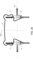
figure 23 diagrammatically shows a spring associated with two opposite plate coupling portions, in which the actions of the spring are broken down in radial and axial directions to show how the radial actions substantially compensate each other and the resulting are axial actions which constantly and elastically bias the pads as they move away from the disc. - With reference to the figures, a disc brake, in particular for use on motor vehicles, is globally indicated by
reference numeral 1. In the specific case, it is a disc brake of the floating caliper type. However, the invention is also applicable to brakes with fixed calipers. - The
disc brake 1 comprises acaliper 2 and abrake disc 3, in which thebrake disc 3 defines arotation axis 10. Thecaliper 2 is arranged straddling thebrake disc 3 and can be fixed to abracket 4 by means of a sliding support (e.g.fig. 1-2 ). - The
bracket 4 is fixed to a vehicle suspension, while thebrake disc 3, provided with anannular braking band 5, can be connected to the wheel hub of the vehicle (not shown). - The
brake disc 1 comprises anassembly 100, wherein theassembly 100 comprises at least twopads 6 having asupport plate 7 and afriction material coating 8, each of said at least twopads 6 is adapted to be accommodated in anappropriate pocket 9 of acaliper 2 so that each of said at least twopads 6 can be positioned on a side of abrake disc 3 of a disc brake 5 (e.g.fig. 3-5 ). - The
pads 6 can be displaced mainly in axial direction (parallel to therotation axis 10 of the brake disc 3) towards thebrake disc 3 by means of thrust means, e.g. such as one or more hydraulic cylinder-piston units 11 arranged in thecaliper 2, so as to clamp, via thefriction material 8, a sector of thebraking band 5, the surface and shape of which corresponds to those of the friction lining 8. - The
support plate 7 of thepads 6 has a substantially rectangular shape and forms twoears 12 protruding outwards from thesupport plate 7. - Each one of the two
ears 12 forms anabutment wall 14 adapted to be inserted in thepockets 9 of thecaliper 2. Advantageously, theabutment wall 14" has an angular shape, forming a first abutment wall 14' and a second abutment wall 14' adapted to abut against a plate mounted on two different surfaces of apocket 9 of the caliper 2 (e.g.fig. 5-7 ). - Furthermore, each of the
ears 12 forms acoupling seat 13. - Furthermore, the
assembly 100 further comprises at least onespring 15 shaped to be positioned straddling thebrake disc 3, and which applies an elastic preload on thepads 6 so as to bias thepads 6 elastically away from thebrake disc 3. - The at least one
spring 15 may perform the further function of stopping thepads 6 elastically in thepockets 9 so as to reduce the onset of vibrations and noise due to movements of the pads with respect to thecaliper 2. - According to an aspect of the invention, the
spring 15 is configured so as to be directly connected only to the pads 6 (fig. 3-5 ). Therefore, thespring 15 is not constrained by any otherdisc brake component 1 except for thepads 6. - Such a configuration increases the assembly flexibility of the at least one
spring 15 to thedisc brake 1 because the at least onespring 15 is connected exclusively to thepads 6, and thus may be implemented indifferently tovarious disc brakes 1 andvarious calipers 2, with no need to adaptsuch disc brakes 1 orsuch calipers 2 to thespring 15 or vice versa. By virtue of such a configuration, during wear of thefriction material 8 of thepads 6, thespring 15 rotates like a hinge about the spring-coupling plate portion 37, sliding thespring 15 against said innerlower edge 25 and said upper spring-coupling plate portion edge 29 to apply an elastic bias for distancing thepads 6 from the brake, when the braking action ceases, substantially globally directed in the axial direction A-A. - With further advantage, such a configuration of the
spring 15 is space-saving, because it makes up for the formation on thecaliper 2 of a specific connection portion for thespring 15. - According to a further aspect of the invention, two
springs 15 are arranged straddling thebrake disc 3, so as to apply an elastic preload on thepads 6. - Specifically, each of the two
springs 15 is connected to theear 12 of afirst pad 6 and to the correspondingopposite ear 12 of theother pad 6, respectively. - According to an embodiment of the invention, at least one
spring 15 is substantially shaped as an inverted "U" (fig. 8-9 ). - The at least one
spring 15 defines a symmetry plane 16 (geometric, not material) which is transverse to therotation axis 10 of thebrake disc 3 when at least onespring 15 is mounted in the operating position. - The at least one
spring 15 consists of two coupling portions orspring arms 17 and of abridge portion 18 interposed between the two coupling portions orspring arms 17. - The two coupling portions or
spring arms 17 are configured to couple to arespective ear 12 of the twopads 6 and said two coupling portions orspring arms 17 are symmetrical with respect to thesymmetry plane 16. - According to this embodiment, the
spring 15 is deformed elastically (in particular, by accumulating elastic energy) by a relative movement of the coupling portions orspring arms 17, moved by therespective pads 6, with respect to thebridge portion 18. - According to an embodiment, each of the two coupling portions or
spring arms 17 is connected to thebridge portion 18 by means of afirst connector 19, wherein thefirst connector 19 is shaped as a loop or arc of circumference. - Advantageously, such a shape of the
first connector 19 ensures that the elastic return force of the spring 15 (caused by the elastic deformation of thespring 15 by the action of the pads 6) is incremental as the wear of thepads 6 varies, i.e. as the distance between the two coupling pads 6 (and therefore the distance between the two coupling portions orspring arms 17 attached to the pads 6). - According to an embodiment, each of the coupling portions or
spring arms 17 of thespring 15 is substantially "Z"-shaped. - In particular, each of the coupling portions or
spring arms 17 consists of a firstdiagonal portion 21" and a seconddiagonal portion 21", which are substantially parallel to each other, between which areturn portion 22, which is substantially transversal to the twodiagonal portions 21", 21", is interposed. - The
return portion 22 is configured so as to lie on arespective coupling seat 13 of theears 12. - Advantageously, such configuration of the
return portion 22 guarantees that thespring 15 is constantly connected to thepads 6 when the wear of thepads 6 varies, i.e. with the distance between the two pads 6 (and therefore the distance between the two coupling portions orspring arms 17 coupled to the pads 6), and in particular when thepads 6 are new and the spring is very open (fig. 3-4 ). - According to a further embodiment, the first diagonal portion 21' of each of the coupling portions or
spring arms 17 is connected at a first end thereof to thereturn portion 22 by means of asecond connector 24, wherein thesecond connector 24 is shaped as a loop or arc of circumference. - Advantageously, such a shape of the
second connector 24 further ensures that the elastic return force of the spring 15 (caused by the elastic deformation of thespring 15 by the action of the pads 6) is incremental as the wear of thepads 6 varies, i.e. with the distance between the two coupling pads 6 (and therefore the distance between the two coupling portions orspring arms 17 attached to the pads 6) when thedisc brake 1 is not actuated. - According to an embodiment, a second end of the diagonal portion 21' forms a hook-shaped
end portion 23. - Advantageously, such a
hooked end portion 23 further guarantees a correct and stable connection of thespring 15 to theears 12 of thepads 6. - According to an embodiment, the
spring 15 is configured so that, in the working position, the coupling portions orspring arms 17 are interposed between thepads 6 and thebrake disc 3. - According to an embodiment, the
spring 15 is of the leaf type. - According to a further embodiment, the
spring 15 is formed in a single strip-shaped steel piece shaped so as to display only curvatures about axes which are substantially parallel to one another and substantially parallel to thesymmetry plane 16 of thespring 15. - Advantageously, this simplifies the production process of
spring 15, e.g. starting from sheet material, e.g. spring steel, which is sheared into strips and then bent and heat-treated to achieve its elastic return performance from said bent shape. - According to a further aspect of the invention, a
caliper 2 comprises theassembly 100 described above. - According to an advantageous embodiment, the
caliper 2 is of the "floating" type. - According to a further aspect of the invention, a
disc brake 1 comprises theassembly 100 described above and thecaliper 2 described above. - It is apparent that only some particular embodiments of the present invention have been described, to which those skilled in the art will be able to make all the changes required to adapt it to particular applications, without departing from the scope of protection of the present invention.
- According to a general embodiment, an
assembly 100 comprises at least twopads 6 having asupport plate 7 and afriction material lining 8. Each of said at least twopads 6 is adapted to be accommodated in apocket 9 of acaliper 2 so that each of said at least twopads 6 can be positioned on a side of abrake disc 3 of adisc brake 1 facing opposite braking surfaces 36. - Said
brake disc 3 is a rotor adapted to rotate about arotation axis 10 which defines an axial direction A-A, parallel to saidrotation axis 10, a radial direction R-R, orthogonal to saidrotation axis 10, and a circumferential direction C-C orthogonal to said axial A-A and radial R-R directions and a tangential direction T-T orthogonal to a radial R-R and circumferential C-C direction at their point of intersection. - Said
assembly 100 further comprises at least onespring 15, shaped to be arranged straddling thedisc brake 3. - Said
spring 15 applies an elastic bias on thepads 6 so as to bias thepads 6 elastically away from thebrake disc 3. - Said at least one
spring 15 is configured to be directly connected only to thepads 6. - Said
support plate 7 comprises at least oneplate coupling portion 37. - In a section of said
plate coupling portion 37 on a plane containing the axial direction A-A and the radial direction R-R, saidplate coupling portion 37 comprises: - an inner
lower edge 25, adapted to face thebrake disc 3 in the radially inward direction or towards thedisc rotation axis 10; - an inner
upper edge 26, adapted to face thebrake disc 3 in the radially outward direction or opposite to thedisc rotation axis 10. - Said inner
upper edge 26 continues on a directupper surface 27 according to an axial direction A-A parallel to saiddisc rotation axis 10, thus forming an upper spring-coupling plate portion edge 29. - Advantageously, said
spring 15 is always in contact exclusively with: - said inner
lower edge 25 and said upper spring-coupling plate portion edge 29. - According to an embodiment, said
spring 15 is a wire spring made in one piece. - According to an embodiment, said
spring 15 is a wire spring having a circular cross-section. - According to an embodiment, said
spring 15 is a wire spring made in one piece and saidspring 15 is always in contact exclusively with a point or a line of said innerlower edge 25 and said upper spring-coupling plate portion edge 29. - According to an embodiment, said inner
upper edge 26 is radially arranged on the side opposite to said innerlower edge 25. - Said inner
upper edge 26 continues on a directupper surface 27 according to an axial direction A-A parallel to saiddisc rotation axis 10. - Said
upper surface 27 continues on an outerupper edge 28 adapted to be rotated in the opposite direction to thebrake disc 3. - Said
spring 15 is always in contact with said upperinner edge 26 or saidupper surface 27 or said upperouter edge 28. - According to an embodiment, said
spring 15 avoids resting on anything else but said at least twopads 6, thus avoiding the connection to saidcaliper 2 for relieving all or part of the elastic reaction thereon. - According to an embodiment, said
assembly 100 comprises twosprings 15 adapted to be arranged straddling thebrake disc 3, so as to bias thepads 6 elastically and wherein both said twosprings 15 are configured to be directly connected only to thepads 6. - According to an embodiment, said two
springs 15 are disconnected at opposite sides of said twopads 6. - According to an embodiment, the
support plate 7 of thepads 6 is substantially rectangular in shape, saidsupport plate 7 forms twoears 12 which extend towards the outside of thesupport plate 7 in circumferential direction C-C. - According to an embodiment, said at least one
spring 15 cooperates with at least one of saidears 12. - According to an embodiment, each of the two
ears 12 forms anabutment wall 14, adapted to be abuttingly inserted into thepockets 9 of thecaliper 2, wherein theabutment wall 14 is angular in shape, thus forming a first abutment wall 14' and asecond abutment wall 14" adapted to abut against metal sheets mounted to two different surfaces of apocket 9 of thecaliper 2; and acoupling seat 13. - According to an embodiment, each of the two
springs 15 is connected to theear 12 of afirst pad 6 and to theear 12 of theother pad 6, respectively, either directly or indirectly facing saidfirst pad ear 12. - According to an embodiment, said at least one
plate coupling portion 37 comprises said upper spring-coupling plate portion edge 29, one inner pad coupling portion side 30, adapted to face either directly or indirectly saidbrake disc 3, and a lower spring-coupling plate portion edge 30 comprising said innerlower edge 25 which continues on a lower surface 31 directed according to an axial direction A-A parallel to saiddisc rotation axis 10. - According to an embodiment, said upper spring-coupling plate portion edge 29 comprises an upper
spring seat edge 32 shaped to fit intimately with a coupling portion orspring arms 17. - According to an embodiment, said lower spring-coupling plate portion edge 31 comprises a lower
spring seat edge 34 shaped to fit intimately with a coupling portion orspring arms 17. - According to an embodiment, said inner pad coupling portion side 30 comprises an inner
spring seat side 33 shaped to fit intimately with a coupling portion orspring arms 17. - According to an embodiment, the at least one
spring 15 is substantially inverted "U"-shaped, and said at least onespring 15 defines asymmetry plane 16. - According to an embodiment, the at least one
spring 15 comprises two coupling portions orspring arms 17 and of abridge portion 18, saidbridge portion 18 being interposed between the two coupling portions orspring arms 17. - According to an embodiment, said coupling portions or
spring arms 17 are configured to be coupled to arespective ear 12 of the twopads 6. - According to an embodiment, said two coupling portions or
spring arms 17 are symmetrical with respect to thesymmetry plane 16. - According to an embodiment, the
spring 15 is elastically deformable by means of a relative movement of the coupling portions orspring arms 17, said coupling portions orspring arms 17 being movable by therespective pads 6, with respect to thebridge portion 18. - According to an embodiment, each of the two coupling portions or
spring arms 17 is connected to thebridge portion 18 by means of afirst connector 19, wherein saidfirst connector 19 is shaped as a loop or arc of circumference. - According to an embodiment, said
first connector 19 is spiral-shaped. - According to an embodiment, said
first connection 19 is spiral-shaped with at least onefirst connection loop 35 forming an angle of at least 360 DEG. - According to an embodiment, each of the coupling portions or
spring arms 17 of thespring 15 is substantially "Z"-shaped, and each of the coupling portions orspring arms 17 comprises: - a first diagonal portion or first inclined portion 21';
- a second diagonal portion or second
inclined portion 21"; - a
return portion 22. - According to an embodiment, the first diagonal portion 21' and the second
diagonal portion 21" are substantially parallel to each other, and thereturn portion 22 is interposed between the first diagonal portion 21' and the seconddiagonal portion 21", said return portion being substantially transverse to the first diagonal portion 21' and to the seconddiagonal portion 21". - According to an embodiment, the
return portion 22 is configured so as to lie on arespective coupling seat 13 of theears 12. - According to an embodiment, the first diagonal portion 21' of each of the coupling portions or
spring arms 17 is connected at a first end thereof to thereturn portion 22 by means of asecond connector 24, wherein thesecond connector 24 is shaped as a loop or arc of circumference. - According to an embodiment, a second end of the diagonal portion 21' forms a hook-shaped
end portion 23. - According to an embodiment, the
spring 15 is configured so that, in the working position, the coupling portions orspring arms 17 are interposed between thepads 6 and thebrake disc 3. - According to an embodiment, the
spring 15 is of the wire type. - According to an embodiment, the
spring 15 is a spring leaf. - According to an embodiment, the
spring 15 is formed in a single strip-shaped steel piece shaped so as to display only curvatures about axes which are substantially parallel to one another and substantially parallel to thesymmetry plane 16 of thespring 15. - The present invention further relates to a
caliper 2 comprising anassembly 100, saidassembly 100 comprising at least twopads 6 and at least onespring 15 according to any one of the embodiments described above. - According to an embodiment, the at least one
spring 15 is configured to perform the further function of stopping thepads 6 elastically in thepockets 9 so as to reduce the onset of vibrations and noise due to movements of the pads with respect to thecaliper 2. - According to an embodiment, said
caliper body 2 is of the "floating" type. - The present invention further relates to a
disc brake 1 comprising anassembly 100 comprising at least twopads 6 and at least onespring 15 according to any one of the embodiments described above; acaliper 2; and abrake disc 3. - The present invention further relates to a method for biasing two facing
brake pads 6 constantly and elastically by means of aspring 15, wherein there are provided the steps of: - providing an assembly according to any one of the embodiments described above; and
- during wear of the
friction material 8 of thepads 6, rotating thespring 15 like a hinge about the spring-coupling plate portion 37, sliding thespring 15 against said innerlower edge 25 and said upper spring-coupling plate portion edge 29 to apply an elastic bias for distancing thepads 6 from the brake, when the braking action ceases, substantially globally directed in the axial direction A-A. -
- 1.
- Disc brake
- 2.
- Caliper
- 3.
- Brake disc
- 4.
- Bracket
- 5.
- Braking band
- 6.
- Pads
- 7.
- Support plate
- 8.
- Friction material
- 9.
- Pockets
- 10.
- Rotation axis (of the brake disc)
- 11.
- Hydraulic cylinder-piston
- 12.
- Ears (of the pads)
- 13.
- Coupling seats
- 14.
- Abutment wall
- 14'.
- First abutment wall
- 14".
- Second abutment wall
- 15.
- Spring
- 16.
- Symmetry plane (of the spring)
- 17.
- Coupling portion or spring arm
- 18.
- Bridge portion
- 19.
- First connector
- 21'.
- First diagonal portion or first inclined portion
- 21".
- Second diagonal portion or second inclined portion
- 22.
- Return portion
- 23.
- Hook-shaped end portion
- 24.
- Second connector
- 25.
- Inner lower edge
- 26.
- Inner upper edge
- 27.
- Upper surface
- 28.
- Outer upper edge
- 29.
- Upper edge of plate coupling portion to the spring
- 30.
- Inner pad coupling portion side
- 31.
- Lower spring-coupling plate portion edge
- 32.
- Upper edge spring seat
- 33.
- Inner side spring seat
- 34.
- Lower edge spring seat
- 35.
- First connection loop
- 36.
- Disc brake braking surfaces
- 37.
- Plate coupling portion to the spring
- 100.
- Pad-spring assembly
- A-A
- axial direction
- R-R
- radial direction
- C-C
- circumferential direction
- T-T
- tangential direction
Claims (14)
- An assembly (100) comprising:- at least two pads (6) having a support plate (7) and a friction material coating (8), each of said at least two pads (6) being adapted to be accommodated in a pocket (9) of a caliper (2) so that each of said at least two pads (6) can be positioned on a side of a brake disc (3) of a disc brake (1) facing opposite braking surfaces (36);
said brake disc (3) being a rotor adapted to rotate about a rotation axis (10) which defines an axial direction (A-A), parallel to said rotation axis (10), a radial direction (R-R), orthogonal to said rotation axis (10), and a circumferential direction (C-C) orthogonal to said axial (A-A) and radial (R-R) directions and a tangential direction (T-T) duly orthogonal to a radial (R-R) and circumferential (C-C) direction at their point of intersection;- at least one spring (15), shaped to be arranged straddling the disc brake (3), wherein said spring (15) applies an elastic bias on the pads (6) so as to bias the pads (6) elastically away from the brake disc (3);wherein said at least one spring (15) is configured to be directly connected only to the pads (6);said support plate (7) comprising at least one plate coupling portion (37),wherein, in a section of said plate coupling portion (37) on a plane containing the axial direction (A-A) and the radial direction (R-R), said plate coupling portion (37) comprises:- an inner lower edge (25), adapted to face the brake disc (3) in the radially inward direction or towards the disc rotation axis (10);- an inner upper edge (26), adapted to face the brake disc (3) in the radially outward direction or opposite to the disc rotation axis (10);- said inner upper edge (26) continues on a direct upper surface (27) according to an axial direction (A-A) parallel to said disc rotation axis (10), thus forming an upper spring-coupling plate portion edge (29);and wherein said spring (15) is always in contact exclusively with:- said inner lower edge (25)
and- said upper spring-coupling plate portion edge (29);so that, during wear of the friction material (8) of the pads (6), the spring (15) rotates like a hinge about the spring-coupling plate portion (37), sliding the spring (15) against said inner lower edge (25) and said upper spring-coupling plate portion edge (29) to apply an elastic bias for distancing the pads (6) from the brake, when the braking action ceases, substantially globally directed in the axial direction (A-A). - An assembly (100) according to claim 1, wherein said spring (15) is a wire spring made in one piece;
orwherein said spring (15) is a wire spring having a circular cross-section;or whereinsaid spring (15) is a spring in one piece;wherein said spring (15) is always in contact exclusively with a point or a line of said inner lower edge (25) and said upper spring-coupling plate portion edge (29). - An assembly (100) according to claim 1 or 2, wherein said inner upper edge (26) is radially arranged on the side opposite to said inner lower edge (25) and whereinsaid inner upper edge (26) continues on a direct upper surface (27) according to an axial direction (A-A) parallel to said disc rotation axis (10); and whereinsaid upper surface (27) continues on an outer upper edge (28) adapted to be rotated in the opposite direction to the brake disc (3); and whereinsaid spring (15) is always in contact with said upper inner edge (26) or said upper surface (27) or said upper outer edge (28).
- An assembly (100) according to any one of the preceding claims, wherein:said spring (15) avoids resting on anything else but said at least two pads (6), thus avoiding the connection to said caliper (2) for relieving all or part of the elastic reaction thereon;or whereinsaid assembly (100) comprises two springs (15) adapted to be arranged straddling the brake disc (3), in order to bias the pads (6) elastically and wherein both said two springs (15) are configured to be directly connected only to the pads (6);and whereinsaid two springs (15) are disconnected at opposite sides of said two pads (6).
- An assembly (100) according to any one of the preceding claims, wherein the support plate (7) of the pads (6) is substantially rectangular in shape, said support plate (7) forms two ears (12) which extend towards the outside of the support plate (7) in circumferential direction (C-C);
and wherein
said at least one spring (15) cooperates with at least one of said ears (12). - An assembly (100) according to claim 5, wherein each of the two ears (12) forms:- an abutment wall (14), adapted to be abuttingly inserted into the pockets (9) of the caliper (2), wherein the abutment wall (14) has is angular in shape, thus forming a first abutment wall (14') and a second abutment wall (14") adapted to abut against metal sheets mounted to two different surfaces of a pocket (9) of the caliper (2); and- a coupling seat (13);or wherein
each of the two springs (15) is connected to the ear (12) of a first pad (6) and to the ear (12) of the other pad (6), respectively, either directly or indirectly facing said first pad ear (12). - An assembly (100) according to any one of the preceding claims, wherein said at least one plate coupling portion (37) comprises said upper spring-coupling plate portion edge (29), one inner pad coupling portion side (30), adapted to face either directly or indirectly said brake disc (3), and a lower spring-coupling plate portion edge (30) comprising said inner lower edge (25) which continues on a lower surface (31) directed according to an axial direction (A-A) parallel to said disc rotation axis (10);
and whereinsaid upper spring-coupling plate portion edge (29) comprises an upper spring seat edge (32) shaped to fit intimately with a coupling portion or spring arm (17);and whereinsaid lower spring-coupling plate portion edge (31) comprises a lower spring seat edge (34) shaped to fit intimately with a coupling portion or spring arm (17);and whereinsaid inner pad coupling portion side (30) comprises an inner spring seat side (33) shaped to fit intimately with a coupling portion or spring arm (17). - An assembly (100) according to any one of the preceding claims, wherein the at least one spring (15) is substantially inverted "U"-shaped, and said at least one spring (15) defines a symmetry plane (16);
and whereinthe at least one spring (15) comprises two coupling portions or spring arms (17) and of a bridge portion (18), said bridge portion (18) being interposed between the two coupling portions or spring arms (17),and wherein said coupling portions or spring arms (17) are configured to be coupled to a respective ear (12) of the two pads (6),and wherein said two coupling portions or spring arms (17) are symmetrical with respect to the symmetry plane (16);and whereinthe spring (15) is elastically deformable by means of a relative movement of the coupling portions or spring arms (17), said coupling portions or spring arms (17) being movable by the respective pads (6), with respect to the bridge portion (18);and whereineach of the two coupling portions or spring arms (17) is connected to the bridge portion (18) by means of a first connector (19), wherein said first connector (19) is shaped as a loop or arc of circumference;and wherein said first connection (19) is spiral-shaped;and wherein said first connection (19) is spiral-shaped with at least one first connection loop (35) forming an angle of at least 360 DEG;and whereineach of the coupling portions or spring arms (17) of the spring (15) is substantially "Z"-shaped, and each of the coupling portions or spring arms (17) comprises:- a first diagonal portion or first inclined portion (21');- a second diagonal portion or second inclined portion (21");- a return portion (22);and wherein the first diagonal portion (21') and the second diagonal portion (21") are substantially parallel to each other, andthe return portion (22) is interposed between the first diagonal portion (21') and the second diagonal portion (21"), said return portion being substantially transverse to the first diagonal portion (21') and to the second diagonal portion (21"). - An assembly (100) according to claim 8, wherein the return portion (22) is configured so as to lie on a respective coupling seat (13) of the ears (12);
or whereinthe first diagonal portion (21') of each of the coupling portions or spring arms (17) is connected at a first end thereof to the return portion (22) by means of a second connector (24), wherein the second connector (24) is shaped as a loop or arc of circumference;or whereina second end of the diagonal portion (21') forms a hook-shaped end portion (23);or whereinthe spring (15) is configured so that, in the working position, the coupling portions or spring arms (17) are interposed between the pads (6) and the brake disc (3);or whereinthe spring (15) is of the wire type;or whereinthe spring (15) is of the leaf type;or whereinthe spring (15) is formed in a single strip-shaped steel piece shaped so as to display only curvatures about axes which are substantially parallel to one another and substantially parallel to the symmetry plane (16) of the spring (15). - A caliper (2) comprising an assembly (100), said assembly (100) comprising at least two pads (6) and at least one spring (15) according to any one of the preceding claims.
- A caliper (2) according to claim 10, wherein the at least one spring (15) is configured to perform the further function of stopping the pads (6) elastically in the pockets (9) so as to reduce the onset of vibrations and noise due to movements of the pads with respect to the caliper (2).
- A caliper (2) according to claim 10 or 11, wherein the caliper (2) is of the "floating" type.
- A disc brake (1) comprising:- a caliper (2) according to one of the claims from 10 to 12; and- a brake disc (3).
- A method for constantly and elastically biasing two facing brake pads (6) by means of a spring (15), wherein there are provided the steps of:- providing an assembly according to at least one of the claims from 1 to 9;- connecting said at least one spring (15) directly and exclusively to the pads (6);- during the wear of the friction material (8) of the pads (6), rotating the spring (15) like a hinge about the spring-coupling plate portion (37), sliding the spring (15) against said inner lower edge (25) and said upper spring-coupling plate portion edge (29) to apply an elastic bias distancing the pads (6) away from the brake, when the braking action ceases, substantially globally directed in the axial direction (A-A).
Applications Claiming Priority (3)
| Application Number | Priority Date | Filing Date | Title |
|---|---|---|---|
| IT102018000020527A IT201800020527A1 (en) | 2018-12-20 | 2018-12-20 | ASSEMBLY OF PADS-SPRING FOR DISC BRAKE |
| IT102019000023940A IT201900023940A1 (en) | 2019-12-13 | 2019-12-13 | Assembly of at least two brake pads and at least one spring |
| PCT/IB2019/061201 WO2020129012A1 (en) | 2018-12-20 | 2019-12-20 | Assembly of at least two brake pads and at least one spring |
Publications (2)
| Publication Number | Publication Date |
|---|---|
| EP3899306A1 EP3899306A1 (en) | 2021-10-27 |
| EP3899306B1 true EP3899306B1 (en) | 2024-06-26 |
Family
ID=69165448
Family Applications (1)
| Application Number | Title | Priority Date | Filing Date |
|---|---|---|---|
| EP19836587.6A Active EP3899306B1 (en) | 2018-12-20 | 2019-12-20 | Assembly of at least two brake pads and at least one spring |
Country Status (5)
| Country | Link |
|---|---|
| US (1) | US11852207B2 (en) |
| EP (1) | EP3899306B1 (en) |
| JP (1) | JP7589151B2 (en) |
| CN (1) | CN113195920B (en) |
| WO (1) | WO2020129012A1 (en) |
Families Citing this family (4)
| Publication number | Priority date | Publication date | Assignee | Title |
|---|---|---|---|---|
| IT202100000749A1 (en) | 2021-01-18 | 2022-07-18 | Brembo Spa | RIBBON SPRING AND SPRING RIBBON AND BRAKE PAD ASSEMBLY |
| IT202100000743A1 (en) | 2021-01-18 | 2022-07-18 | Brembo Spa | RIBBON SPRING AND SPRING RIBBON AND BRAKE PAD ASSEMBLY |
| CN217440641U (en) * | 2022-04-29 | 2022-09-16 | 蔚来汽车科技(安徽)有限公司 | Brake caliper assembly, brake and vehicle |
| IT202300004659A1 (en) * | 2023-03-13 | 2024-09-13 | Brembo Spa | REPOSITIONING SPRING, BRAKE CALIPER AND REPOSITIONING SPRING ASSEMBLY |
Citations (4)
| Publication number | Priority date | Publication date | Assignee | Title |
|---|---|---|---|---|
| US4408681A (en) | 1980-06-23 | 1983-10-11 | Tokico Ltd. | Disc brake |
| US20120205205A1 (en) | 2011-02-10 | 2012-08-16 | Akebono Corporation | Pad retraction device |
| WO2012174031A2 (en) | 2011-06-13 | 2012-12-20 | Anstro Manufacturing, Inc. | Friction pad spreader, assembly including same and method of mounting thereof |
| WO2018017966A1 (en) | 2016-07-21 | 2018-01-25 | Preferred Tool & Die, Inc. | Caliper hardware providing separation between pad and rotor |
Family Cites Families (16)
| Publication number | Priority date | Publication date | Assignee | Title |
|---|---|---|---|---|
| JP2002039236A (en) * | 2000-07-25 | 2002-02-06 | Aisin Seiki Co Ltd | Floating caliper type disc brake |
| WO2002033282A1 (en) | 2000-10-18 | 2002-04-25 | Akebono Corporation North America | Spring for retracting and retaining a pad in a caliper type disc brake assembly |
| US6719105B1 (en) | 2002-06-26 | 2004-04-13 | Kelsey-Hayes Company | Pad retraction spring for disc brake assembly |
| JP2004176868A (en) * | 2002-11-28 | 2004-06-24 | Advics:Kk | Disc brake |
| JP4546398B2 (en) * | 2003-07-31 | 2010-09-15 | フレニ・ブレンボ エス・ピー・エー | Spring member for disc brake caliper and caliper for disc brake |
| US7784591B2 (en) * | 2006-03-15 | 2010-08-31 | Kelsey-Hayes Company | Defined brake pad abutment |
| JP2012072830A (en) | 2010-09-28 | 2012-04-12 | Akebono Brake Ind Co Ltd | Pad return mechanism of disc brake |
| JP2012189188A (en) * | 2011-03-14 | 2012-10-04 | Akebono Brake Ind Co Ltd | Apparatus for returning disk brake pad |
| US9062729B2 (en) | 2012-11-06 | 2015-06-23 | Akebono Brake Corporation | Brake pad coupler |
| US10718393B2 (en) * | 2014-05-27 | 2020-07-21 | Freni Brembo S.P.A. | Spring of a caliper of a disc brake |
| DE112015003544T5 (en) * | 2014-08-01 | 2017-06-01 | Freni Brembo S.P.A. | Pad arrangement of a disc brake and printing device |
| US9670977B2 (en) * | 2014-09-11 | 2017-06-06 | Akebono Brake Industry Co., Ltd. | High-low pad retraction spring |
| EP3250839B1 (en) * | 2015-01-30 | 2022-04-13 | BREMBO S.p.A. | Pad and spring assembly for a disc brake caliper |
| IT201600130800A1 (en) * | 2016-12-23 | 2018-06-23 | Freni Brembo Spa | Spring device for disc brake, pad and spring assembly and brake caliper |
| DE102017222639A1 (en) * | 2017-01-31 | 2018-08-02 | Continental Teves Ag & Co. Ohg | Fixed caliper motor vehicle tamper disc brake with a steel sheet bowing clearance spring |
| DE102017204696A1 (en) | 2017-03-21 | 2018-09-27 | Continental Teves Ag & Co. Ohg | One-piece return spring for vehicle disc brake pads |
-
2019
- 2019-12-20 CN CN201980084775.2A patent/CN113195920B/en active Active
- 2019-12-20 WO PCT/IB2019/061201 patent/WO2020129012A1/en not_active Ceased
- 2019-12-20 US US17/416,062 patent/US11852207B2/en active Active
- 2019-12-20 EP EP19836587.6A patent/EP3899306B1/en active Active
- 2019-12-20 JP JP2021536008A patent/JP7589151B2/en active Active
Patent Citations (4)
| Publication number | Priority date | Publication date | Assignee | Title |
|---|---|---|---|---|
| US4408681A (en) | 1980-06-23 | 1983-10-11 | Tokico Ltd. | Disc brake |
| US20120205205A1 (en) | 2011-02-10 | 2012-08-16 | Akebono Corporation | Pad retraction device |
| WO2012174031A2 (en) | 2011-06-13 | 2012-12-20 | Anstro Manufacturing, Inc. | Friction pad spreader, assembly including same and method of mounting thereof |
| WO2018017966A1 (en) | 2016-07-21 | 2018-01-25 | Preferred Tool & Die, Inc. | Caliper hardware providing separation between pad and rotor |
Also Published As
| Publication number | Publication date |
|---|---|
| CN113195920A (en) | 2021-07-30 |
| EP3899306A1 (en) | 2021-10-27 |
| JP2022515189A (en) | 2022-02-17 |
| CN113195920B (en) | 2023-08-11 |
| WO2020129012A1 (en) | 2020-06-25 |
| JP7589151B2 (en) | 2024-11-25 |
| US20220056970A1 (en) | 2022-02-24 |
| US11852207B2 (en) | 2023-12-26 |
Similar Documents
| Publication | Publication Date | Title |
|---|---|---|
| EP3899306B1 (en) | Assembly of at least two brake pads and at least one spring | |
| CN108138877B (en) | Wear optimized blade design | |
| US20180106308A1 (en) | Disc Brake for a Commercial Vehicle and Brake Pad Set | |
| US10119581B2 (en) | Disc brake | |
| EP3954919B1 (en) | Brake assembly | |
| US20180347648A1 (en) | Brake pad | |
| EP4107405B1 (en) | Brake pad retainer system, brake pad and vehicle | |
| US9976610B2 (en) | Wear optimized pad design | |
| WO2022153235A1 (en) | Band spring and band spring and brake pad assembly | |
| EP3580470B1 (en) | Wear optimized pad design | |
| HK1250770B (en) | Wear optimized pad design | |
| CA2997351C (en) | Wear optimized pad design | |
| CN110234900A (en) | Disk brake pad and disc brake apparatus | |
| IT201800020527A1 (en) | ASSEMBLY OF PADS-SPRING FOR DISC BRAKE | |
| JPH11344057A (en) | Disc brakes and friction pads for disc brakes |
Legal Events
| Date | Code | Title | Description |
|---|---|---|---|
| STAA | Information on the status of an ep patent application or granted ep patent |
Free format text: STATUS: UNKNOWN |
|
| STAA | Information on the status of an ep patent application or granted ep patent |
Free format text: STATUS: THE INTERNATIONAL PUBLICATION HAS BEEN MADE |
|
| PUAI | Public reference made under article 153(3) epc to a published international application that has entered the european phase |
Free format text: ORIGINAL CODE: 0009012 |
|
| STAA | Information on the status of an ep patent application or granted ep patent |
Free format text: STATUS: REQUEST FOR EXAMINATION WAS MADE |
|
| 17P | Request for examination filed |
Effective date: 20210616 |
|
| AK | Designated contracting states |
Kind code of ref document: A1 Designated state(s): AL AT BE BG CH CY CZ DE DK EE ES FI FR GB GR HR HU IE IS IT LI LT LU LV MC MK MT NL NO PL PT RO RS SE SI SK SM TR |
|
| DAV | Request for validation of the european patent (deleted) | ||
| DAX | Request for extension of the european patent (deleted) | ||
| STAA | Information on the status of an ep patent application or granted ep patent |
Free format text: STATUS: EXAMINATION IS IN PROGRESS |
|
| 17Q | First examination report despatched |
Effective date: 20230405 |
|
| P01 | Opt-out of the competence of the unified patent court (upc) registered |
Effective date: 20230526 |
|
| GRAP | Despatch of communication of intention to grant a patent |
Free format text: ORIGINAL CODE: EPIDOSNIGR1 |
|
| STAA | Information on the status of an ep patent application or granted ep patent |
Free format text: STATUS: GRANT OF PATENT IS INTENDED |
|
| INTG | Intention to grant announced |
Effective date: 20240219 |
|
| GRAS | Grant fee paid |
Free format text: ORIGINAL CODE: EPIDOSNIGR3 |
|
| GRAA | (expected) grant |
Free format text: ORIGINAL CODE: 0009210 |
|
| STAA | Information on the status of an ep patent application or granted ep patent |
Free format text: STATUS: THE PATENT HAS BEEN GRANTED |
|
| AK | Designated contracting states |
Kind code of ref document: B1 Designated state(s): AL AT BE BG CH CY CZ DE DK EE ES FI FR GB GR HR HU IE IS IT LI LT LU LV MC MK MT NL NO PL PT RO RS SE SI SK SM TR |
|
| REG | Reference to a national code |
Ref country code: GB Ref legal event code: FG4D |
|
| REG | Reference to a national code |
Ref country code: CH Ref legal event code: EP |
|
| REG | Reference to a national code |
Ref country code: DE Ref legal event code: R096 Ref document number: 602019054338 Country of ref document: DE |
|
| PG25 | Lapsed in a contracting state [announced via postgrant information from national office to epo] |
Ref country code: BG Free format text: LAPSE BECAUSE OF FAILURE TO SUBMIT A TRANSLATION OF THE DESCRIPTION OR TO PAY THE FEE WITHIN THE PRESCRIBED TIME-LIMIT Effective date: 20240626 |
|
| PG25 | Lapsed in a contracting state [announced via postgrant information from national office to epo] |
Ref country code: FI Free format text: LAPSE BECAUSE OF FAILURE TO SUBMIT A TRANSLATION OF THE DESCRIPTION OR TO PAY THE FEE WITHIN THE PRESCRIBED TIME-LIMIT Effective date: 20240626 Ref country code: HR Free format text: LAPSE BECAUSE OF FAILURE TO SUBMIT A TRANSLATION OF THE DESCRIPTION OR TO PAY THE FEE WITHIN THE PRESCRIBED TIME-LIMIT Effective date: 20240626 |
|
| REG | Reference to a national code |
Ref country code: LT Ref legal event code: MG9D |
|
| PG25 | Lapsed in a contracting state [announced via postgrant information from national office to epo] |
Ref country code: GR Free format text: LAPSE BECAUSE OF FAILURE TO SUBMIT A TRANSLATION OF THE DESCRIPTION OR TO PAY THE FEE WITHIN THE PRESCRIBED TIME-LIMIT Effective date: 20240927 |
|
| PG25 | Lapsed in a contracting state [announced via postgrant information from national office to epo] |
Ref country code: LV Free format text: LAPSE BECAUSE OF FAILURE TO SUBMIT A TRANSLATION OF THE DESCRIPTION OR TO PAY THE FEE WITHIN THE PRESCRIBED TIME-LIMIT Effective date: 20240626 |
|
| REG | Reference to a national code |
Ref country code: NL Ref legal event code: MP Effective date: 20240626 |
|
| PG25 | Lapsed in a contracting state [announced via postgrant information from national office to epo] |
Ref country code: NO Free format text: LAPSE BECAUSE OF FAILURE TO SUBMIT A TRANSLATION OF THE DESCRIPTION OR TO PAY THE FEE WITHIN THE PRESCRIBED TIME-LIMIT Effective date: 20240926 Ref country code: LV Free format text: LAPSE BECAUSE OF FAILURE TO SUBMIT A TRANSLATION OF THE DESCRIPTION OR TO PAY THE FEE WITHIN THE PRESCRIBED TIME-LIMIT Effective date: 20240626 Ref country code: HR Free format text: LAPSE BECAUSE OF FAILURE TO SUBMIT A TRANSLATION OF THE DESCRIPTION OR TO PAY THE FEE WITHIN THE PRESCRIBED TIME-LIMIT Effective date: 20240626 Ref country code: GR Free format text: LAPSE BECAUSE OF FAILURE TO SUBMIT A TRANSLATION OF THE DESCRIPTION OR TO PAY THE FEE WITHIN THE PRESCRIBED TIME-LIMIT Effective date: 20240927 Ref country code: FI Free format text: LAPSE BECAUSE OF FAILURE TO SUBMIT A TRANSLATION OF THE DESCRIPTION OR TO PAY THE FEE WITHIN THE PRESCRIBED TIME-LIMIT Effective date: 20240626 Ref country code: BG Free format text: LAPSE BECAUSE OF FAILURE TO SUBMIT A TRANSLATION OF THE DESCRIPTION OR TO PAY THE FEE WITHIN THE PRESCRIBED TIME-LIMIT Effective date: 20240626 Ref country code: RS Free format text: LAPSE BECAUSE OF FAILURE TO SUBMIT A TRANSLATION OF THE DESCRIPTION OR TO PAY THE FEE WITHIN THE PRESCRIBED TIME-LIMIT Effective date: 20240926 |
|
| PG25 | Lapsed in a contracting state [announced via postgrant information from national office to epo] |
Ref country code: NL Free format text: LAPSE BECAUSE OF FAILURE TO SUBMIT A TRANSLATION OF THE DESCRIPTION OR TO PAY THE FEE WITHIN THE PRESCRIBED TIME-LIMIT Effective date: 20240626 |
|
| REG | Reference to a national code |
Ref country code: AT Ref legal event code: MK05 Ref document number: 1697948 Country of ref document: AT Kind code of ref document: T Effective date: 20240626 |
|
| PG25 | Lapsed in a contracting state [announced via postgrant information from national office to epo] |
Ref country code: NL Free format text: LAPSE BECAUSE OF FAILURE TO SUBMIT A TRANSLATION OF THE DESCRIPTION OR TO PAY THE FEE WITHIN THE PRESCRIBED TIME-LIMIT Effective date: 20240626 |
|
| PG25 | Lapsed in a contracting state [announced via postgrant information from national office to epo] |
Ref country code: PT Free format text: LAPSE BECAUSE OF FAILURE TO SUBMIT A TRANSLATION OF THE DESCRIPTION OR TO PAY THE FEE WITHIN THE PRESCRIBED TIME-LIMIT Effective date: 20241028 |
|
| PG25 | Lapsed in a contracting state [announced via postgrant information from national office to epo] |
Ref country code: PT Free format text: LAPSE BECAUSE OF FAILURE TO SUBMIT A TRANSLATION OF THE DESCRIPTION OR TO PAY THE FEE WITHIN THE PRESCRIBED TIME-LIMIT Effective date: 20241028 |
|
| PG25 | Lapsed in a contracting state [announced via postgrant information from national office to epo] |
Ref country code: PL Free format text: LAPSE BECAUSE OF FAILURE TO SUBMIT A TRANSLATION OF THE DESCRIPTION OR TO PAY THE FEE WITHIN THE PRESCRIBED TIME-LIMIT Effective date: 20240626 |
|
| PG25 | Lapsed in a contracting state [announced via postgrant information from national office to epo] |
Ref country code: EE Free format text: LAPSE BECAUSE OF FAILURE TO SUBMIT A TRANSLATION OF THE DESCRIPTION OR TO PAY THE FEE WITHIN THE PRESCRIBED TIME-LIMIT Effective date: 20240626 |
|
| PG25 | Lapsed in a contracting state [announced via postgrant information from national office to epo] |
Ref country code: AT Free format text: LAPSE BECAUSE OF FAILURE TO SUBMIT A TRANSLATION OF THE DESCRIPTION OR TO PAY THE FEE WITHIN THE PRESCRIBED TIME-LIMIT Effective date: 20240626 Ref country code: IS Free format text: LAPSE BECAUSE OF FAILURE TO SUBMIT A TRANSLATION OF THE DESCRIPTION OR TO PAY THE FEE WITHIN THE PRESCRIBED TIME-LIMIT Effective date: 20241026 |
|
| PG25 | Lapsed in a contracting state [announced via postgrant information from national office to epo] |
Ref country code: CZ Free format text: LAPSE BECAUSE OF FAILURE TO SUBMIT A TRANSLATION OF THE DESCRIPTION OR TO PAY THE FEE WITHIN THE PRESCRIBED TIME-LIMIT Effective date: 20240626 |
|
| PG25 | Lapsed in a contracting state [announced via postgrant information from national office to epo] |
Ref country code: RO Free format text: LAPSE BECAUSE OF FAILURE TO SUBMIT A TRANSLATION OF THE DESCRIPTION OR TO PAY THE FEE WITHIN THE PRESCRIBED TIME-LIMIT Effective date: 20240626 Ref country code: SK Free format text: LAPSE BECAUSE OF FAILURE TO SUBMIT A TRANSLATION OF THE DESCRIPTION OR TO PAY THE FEE WITHIN THE PRESCRIBED TIME-LIMIT Effective date: 20240626 |
|
| PG25 | Lapsed in a contracting state [announced via postgrant information from national office to epo] |
Ref country code: SM Free format text: LAPSE BECAUSE OF FAILURE TO SUBMIT A TRANSLATION OF THE DESCRIPTION OR TO PAY THE FEE WITHIN THE PRESCRIBED TIME-LIMIT Effective date: 20240626 Ref country code: ES Free format text: LAPSE BECAUSE OF FAILURE TO SUBMIT A TRANSLATION OF THE DESCRIPTION OR TO PAY THE FEE WITHIN THE PRESCRIBED TIME-LIMIT Effective date: 20240626 |
|
| PG25 | Lapsed in a contracting state [announced via postgrant information from national office to epo] |
Ref country code: SM Free format text: LAPSE BECAUSE OF FAILURE TO SUBMIT A TRANSLATION OF THE DESCRIPTION OR TO PAY THE FEE WITHIN THE PRESCRIBED TIME-LIMIT Effective date: 20240626 Ref country code: SK Free format text: LAPSE BECAUSE OF FAILURE TO SUBMIT A TRANSLATION OF THE DESCRIPTION OR TO PAY THE FEE WITHIN THE PRESCRIBED TIME-LIMIT Effective date: 20240626 Ref country code: RO Free format text: LAPSE BECAUSE OF FAILURE TO SUBMIT A TRANSLATION OF THE DESCRIPTION OR TO PAY THE FEE WITHIN THE PRESCRIBED TIME-LIMIT Effective date: 20240626 Ref country code: PL Free format text: LAPSE BECAUSE OF FAILURE TO SUBMIT A TRANSLATION OF THE DESCRIPTION OR TO PAY THE FEE WITHIN THE PRESCRIBED TIME-LIMIT Effective date: 20240626 Ref country code: IS Free format text: LAPSE BECAUSE OF FAILURE TO SUBMIT A TRANSLATION OF THE DESCRIPTION OR TO PAY THE FEE WITHIN THE PRESCRIBED TIME-LIMIT Effective date: 20241026 Ref country code: ES Free format text: LAPSE BECAUSE OF FAILURE TO SUBMIT A TRANSLATION OF THE DESCRIPTION OR TO PAY THE FEE WITHIN THE PRESCRIBED TIME-LIMIT Effective date: 20240626 Ref country code: EE Free format text: LAPSE BECAUSE OF FAILURE TO SUBMIT A TRANSLATION OF THE DESCRIPTION OR TO PAY THE FEE WITHIN THE PRESCRIBED TIME-LIMIT Effective date: 20240626 Ref country code: CZ Free format text: LAPSE BECAUSE OF FAILURE TO SUBMIT A TRANSLATION OF THE DESCRIPTION OR TO PAY THE FEE WITHIN THE PRESCRIBED TIME-LIMIT Effective date: 20240626 Ref country code: AT Free format text: LAPSE BECAUSE OF FAILURE TO SUBMIT A TRANSLATION OF THE DESCRIPTION OR TO PAY THE FEE WITHIN THE PRESCRIBED TIME-LIMIT Effective date: 20240626 |
|
| PG25 | Lapsed in a contracting state [announced via postgrant information from national office to epo] |
Ref country code: IT Free format text: LAPSE BECAUSE OF FAILURE TO SUBMIT A TRANSLATION OF THE DESCRIPTION OR TO PAY THE FEE WITHIN THE PRESCRIBED TIME-LIMIT Effective date: 20240626 |
|
| REG | Reference to a national code |
Ref country code: DE Ref legal event code: R026 Ref document number: 602019054338 Country of ref document: DE |
|
| PLBI | Opposition filed |
Free format text: ORIGINAL CODE: 0009260 |
|
| PLAX | Notice of opposition and request to file observation + time limit sent |
Free format text: ORIGINAL CODE: EPIDOSNOBS2 |
|
| PG25 | Lapsed in a contracting state [announced via postgrant information from national office to epo] |
Ref country code: DK Free format text: LAPSE BECAUSE OF FAILURE TO SUBMIT A TRANSLATION OF THE DESCRIPTION OR TO PAY THE FEE WITHIN THE PRESCRIBED TIME-LIMIT Effective date: 20240626 |
|
| 26 | Opposition filed |
Opponent name: VRI-PATENT MONITORING ASSOCIATION Effective date: 20250326 |
|
| PG25 | Lapsed in a contracting state [announced via postgrant information from national office to epo] |
Ref country code: MC Free format text: LAPSE BECAUSE OF FAILURE TO SUBMIT A TRANSLATION OF THE DESCRIPTION OR TO PAY THE FEE WITHIN THE PRESCRIBED TIME-LIMIT Effective date: 20240626 |
|
| REG | Reference to a national code |
Ref country code: CH Ref legal event code: PL |
|
| PLBB | Reply of patent proprietor to notice(s) of opposition received |
Free format text: ORIGINAL CODE: EPIDOSNOBS3 |
|
| PG25 | Lapsed in a contracting state [announced via postgrant information from national office to epo] |
Ref country code: LU Free format text: LAPSE BECAUSE OF NON-PAYMENT OF DUE FEES Effective date: 20241220 |
|
| PG25 | Lapsed in a contracting state [announced via postgrant information from national office to epo] |
Ref country code: SE Free format text: LAPSE BECAUSE OF FAILURE TO SUBMIT A TRANSLATION OF THE DESCRIPTION OR TO PAY THE FEE WITHIN THE PRESCRIBED TIME-LIMIT Effective date: 20240626 |
|
| REG | Reference to a national code |
Ref country code: BE Ref legal event code: MM Effective date: 20241231 |
|
| PG25 | Lapsed in a contracting state [announced via postgrant information from national office to epo] |
Ref country code: BE Free format text: LAPSE BECAUSE OF NON-PAYMENT OF DUE FEES Effective date: 20241231 |
|
| PG25 | Lapsed in a contracting state [announced via postgrant information from national office to epo] |
Ref country code: FR Free format text: LAPSE BECAUSE OF NON-PAYMENT OF DUE FEES Effective date: 20241231 |
|
| PG25 | Lapsed in a contracting state [announced via postgrant information from national office to epo] |
Ref country code: CH Free format text: LAPSE BECAUSE OF NON-PAYMENT OF DUE FEES Effective date: 20241231 |
|
| PG25 | Lapsed in a contracting state [announced via postgrant information from national office to epo] |
Ref country code: IE Free format text: LAPSE BECAUSE OF NON-PAYMENT OF DUE FEES Effective date: 20241220 |
|
| PGFP | Annual fee paid to national office [announced via postgrant information from national office to epo] |
Ref country code: GB Payment date: 20251219 Year of fee payment: 7 |
|
| PLAB | Opposition data, opponent's data or that of the opponent's representative modified |
Free format text: ORIGINAL CODE: 0009299OPPO |
|
| REG | Reference to a national code |
Ref country code: CH Ref legal event code: L10 Free format text: ST27 STATUS EVENT CODE: U-0-0-L10-L00 (AS PROVIDED BY THE NATIONAL OFFICE) Effective date: 20260402 |
|
| PGFP | Annual fee paid to national office [announced via postgrant information from national office to epo] |
Ref country code: DE Payment date: 20251222 Year of fee payment: 7 |
|
| R26 | Opposition filed (corrected) |
Opponent name: VRI-PATENT MONITORING ASSOCIATION Effective date: 20250326 |