EP3899077B1 - Cemented carbide for high demand applications, and method of manufacturing thereof - Google Patents
Cemented carbide for high demand applications, and method of manufacturing thereof Download PDFInfo
- Publication number
- EP3899077B1 EP3899077B1 EP19816463.4A EP19816463A EP3899077B1 EP 3899077 B1 EP3899077 B1 EP 3899077B1 EP 19816463 A EP19816463 A EP 19816463A EP 3899077 B1 EP3899077 B1 EP 3899077B1
- Authority
- EP
- European Patent Office
- Prior art keywords
- cemented carbide
- range
- binder phase
- nitrogen
- iso
- Prior art date
- Legal status (The legal status is an assumption and is not a legal conclusion. Google has not performed a legal analysis and makes no representation as to the accuracy of the status listed.)
- Active
Links
Images

Classifications
-
- B—PERFORMING OPERATIONS; TRANSPORTING
- B22—CASTING; POWDER METALLURGY
- B22F—WORKING METALLIC POWDER; MANUFACTURE OF ARTICLES FROM METALLIC POWDER; MAKING METALLIC POWDER; APPARATUS OR DEVICES SPECIALLY ADAPTED FOR METALLIC POWDER
- B22F3/00—Manufacture of workpieces or articles from metallic powder characterised by the manner of compacting or sintering; Apparatus specially adapted therefor ; Presses and furnaces
- B22F3/12—Both compacting and sintering
- B22F3/14—Both compacting and sintering simultaneously
- B22F3/15—Hot isostatic pressing
-
- C—CHEMISTRY; METALLURGY
- C22—METALLURGY; FERROUS OR NON-FERROUS ALLOYS; TREATMENT OF ALLOYS OR NON-FERROUS METALS
- C22C—ALLOYS
- C22C1/00—Making non-ferrous alloys
- C22C1/04—Making non-ferrous alloys by powder metallurgy
- C22C1/05—Mixtures of metal powder with non-metallic powder
-
- C—CHEMISTRY; METALLURGY
- C22—METALLURGY; FERROUS OR NON-FERROUS ALLOYS; TREATMENT OF ALLOYS OR NON-FERROUS METALS
- C22C—ALLOYS
- C22C1/00—Making non-ferrous alloys
- C22C1/04—Making non-ferrous alloys by powder metallurgy
- C22C1/05—Mixtures of metal powder with non-metallic powder
- C22C1/051—Making hard metals based on borides, carbides, nitrides, oxides or silicides; Preparation of the powder mixture used as the starting material therefor
-
- C—CHEMISTRY; METALLURGY
- C22—METALLURGY; FERROUS OR NON-FERROUS ALLOYS; TREATMENT OF ALLOYS OR NON-FERROUS METALS
- C22C—ALLOYS
- C22C29/00—Alloys based on carbides, oxides, nitrides, borides, or silicides, e.g. cermets, or other metal compounds, e.g. oxynitrides, sulfides
- C22C29/005—Alloys based on carbides, oxides, nitrides, borides, or silicides, e.g. cermets, or other metal compounds, e.g. oxynitrides, sulfides comprising a particular metallic binder
-
- C—CHEMISTRY; METALLURGY
- C22—METALLURGY; FERROUS OR NON-FERROUS ALLOYS; TREATMENT OF ALLOYS OR NON-FERROUS METALS
- C22C—ALLOYS
- C22C29/00—Alloys based on carbides, oxides, nitrides, borides, or silicides, e.g. cermets, or other metal compounds, e.g. oxynitrides, sulfides
- C22C29/02—Alloys based on carbides, oxides, nitrides, borides, or silicides, e.g. cermets, or other metal compounds, e.g. oxynitrides, sulfides based on carbides or carbonitrides
- C22C29/06—Alloys based on carbides, oxides, nitrides, borides, or silicides, e.g. cermets, or other metal compounds, e.g. oxynitrides, sulfides based on carbides or carbonitrides based on carbides, but not containing other metal compounds
- C22C29/067—Alloys based on carbides, oxides, nitrides, borides, or silicides, e.g. cermets, or other metal compounds, e.g. oxynitrides, sulfides based on carbides or carbonitrides based on carbides, but not containing other metal compounds comprising a particular metallic binder
-
- C—CHEMISTRY; METALLURGY
- C22—METALLURGY; FERROUS OR NON-FERROUS ALLOYS; TREATMENT OF ALLOYS OR NON-FERROUS METALS
- C22C—ALLOYS
- C22C29/00—Alloys based on carbides, oxides, nitrides, borides, or silicides, e.g. cermets, or other metal compounds, e.g. oxynitrides, sulfides
- C22C29/02—Alloys based on carbides, oxides, nitrides, borides, or silicides, e.g. cermets, or other metal compounds, e.g. oxynitrides, sulfides based on carbides or carbonitrides
- C22C29/06—Alloys based on carbides, oxides, nitrides, borides, or silicides, e.g. cermets, or other metal compounds, e.g. oxynitrides, sulfides based on carbides or carbonitrides based on carbides, but not containing other metal compounds
- C22C29/08—Alloys based on carbides, oxides, nitrides, borides, or silicides, e.g. cermets, or other metal compounds, e.g. oxynitrides, sulfides based on carbides or carbonitrides based on carbides, but not containing other metal compounds based on tungsten carbide
-
- B—PERFORMING OPERATIONS; TRANSPORTING
- B22—CASTING; POWDER METALLURGY
- B22F—WORKING METALLIC POWDER; MANUFACTURE OF ARTICLES FROM METALLIC POWDER; MAKING METALLIC POWDER; APPARATUS OR DEVICES SPECIALLY ADAPTED FOR METALLIC POWDER
- B22F5/00—Manufacture of workpieces or articles from metallic powder characterised by the special shape of the product
- B22F2005/002—Tools other than cutting tools
-
- B—PERFORMING OPERATIONS; TRANSPORTING
- B22—CASTING; POWDER METALLURGY
- B22F—WORKING METALLIC POWDER; MANUFACTURE OF ARTICLES FROM METALLIC POWDER; MAKING METALLIC POWDER; APPARATUS OR DEVICES SPECIALLY ADAPTED FOR METALLIC POWDER
- B22F2301/00—Metallic composition of the powder or its coating
- B22F2301/15—Nickel or cobalt
-
- B—PERFORMING OPERATIONS; TRANSPORTING
- B22—CASTING; POWDER METALLURGY
- B22F—WORKING METALLIC POWDER; MANUFACTURE OF ARTICLES FROM METALLIC POWDER; MAKING METALLIC POWDER; APPARATUS OR DEVICES SPECIALLY ADAPTED FOR METALLIC POWDER
- B22F2302/00—Metal Compound, non-Metallic compound or non-metal composition of the powder or its coating
- B22F2302/10—Carbide
Definitions
- the present subject matter relates to a wear resistant cemented carbide and method of manufacture for high demand applications and in particular although not exclusively to a corrosion and erosion resistance cemented carbide having a relatively high toughness for a given hardness.
- Cemented carbides have been used extensively for high demand applications such as tools for cutting, machining, drilling or degrading rock. These high wear resistant carbides have found particular application as components within the oil and gas industry where they are used typically for a variety of fluid flow control components including for example choke and control valves, cages, valve seats and seal rings. Their suitability is due largely to their physical and mechanical characteristics including in particular hardness, toughness, strength and wear resistance. Within physical high demand oil and gas applications, conventional cemented carbide components have relatively short lifetimes. Additionally, prediction of in-service performance and the liability is critical due to limited accessibility (e.g. subsea environments) and the extensive production down-time for servicing.
- Flow control components within oil and gas production systems are typically subjected to high fluid velocity flows (> 200 m/s) where the fluid is typically mixed sand/oil/gas/water at variable humidity, flow rate and pH.
- Operating conditions can also include 'sour' conditions that include in particular exposure to H 2 S with an associated increased likelihood of corrosion, pitting and stepwise cracking.
- WO 2017/220533 discloses a process line tool of a cemented carbide comprising in wt%: 2.9-11 Ni; 0.1-2.5 Cr 3 C 2 ; 0.1-1 Mo and WC balance in which the WC comprises a grain size less than or equal to 0.5 ⁇ m.
- CN 102400027 describes a corrosion resistant cemented carbide having wt% 7.3-7.7 Ni, 0.6-1 Cr 3 C 2 , 0.3-0.7 Mo and balance WC.
- WO 2012/045815 describes a cemented carbide for oil and gas applications exhibiting galvanic corrosion resistance comprising WC and wt%: 3-11 Ni; 0.5-7 Cr; 0.3-1.5 Mo; 0-1 Nb and 0-0.2 Co.
- WO 2016/107842 discloses a cemented carbide for fluid handling components such as a seal ring having a composition in wt% 7-11 Ni; 0.5-2.5 Cr 3 C 2 ; 0.5-1 Mo and balance WC having a WC grain size greater than or equal to 4 ⁇ m.
- existing cemented carbides are not optimised for corrosion and mechanical resistance and in particular wet erosion resistance. That is, existing cemented carbides exhibit an unsatisfactory rate of failure when the flow conditions are corrosive and erosive, in particular in the case of erosion induced by a slurry and/or a cavitation phenomenon.
- cemented carbide materials suitable for high demand applications and in particular for use as a constituent or primary material for a component part of such high demand applications. Also provided are cemented carbides having desired toughness, hardness, strength and wear resistant properties to withstand challenging environmental and operative conditions.
- cemented carbides suitable for use as a tool for metal forming or a wear part for fluid handling.
- cemented carbides suitable for use as a component part within oil and gas production including in particular use as a fluid flow component.
- the objectives are achieved by a cemented carbide material having a relatively high hardness, toughness and transverse rupture strength (TRS).
- the cemented carbide materials according to the present invention comprise a hardness in a range 1550 to 1700 HV30 (ISO 3878:1983). Additionally, the present cemented carbide comprise a toughness in a range 9 to 11 MN/m 3/2 (Palmqvist, ISO 28079:2009). Additionally, the present cemented carbides may comprise a TRS of greater than 3000 N/mm 2 (ISO 3327:2009).
- a cemented carbide comprising a hard phase including WC and a binder phase characterised in that: the binder phase content of the cemented carbide is between 7 to 11 wt%; the cemented carbide comprises in wt% 5.9-9 Ni; 0.45-0.75 Cr; 0.55-0.85 Mo and 85-95 or 87-94 WC; and wherein a grain size of the WC is in the range 0.1 to 2 ⁇ m determined by linear intercept.
- the cemented carbide comprises WC as balance wt%.
- the present cemented carbide is particularly suited for use as a component and in particular a fluid flow control component having high erosion, abrasion and corrosion resistance and in particular wet erosion resistance.
- the present cemented carbide is therefore particularly suited for use as a component within oil and gas production.
- the inventors have identified that the recited carbide grade provides high cavitation, corrosion and erosion resistance due, in part, to the recited composition and in particular the binder content (relative to hard phase content) and WC grain size.
- the present cemented carbide provides a component having significantly enhanced slurry erosion resistance and improved cavitation resistance (associated with toughness).
- the cemented carbide comprises Cr, Mo and W in any one or in combination of free/elemental form, or as a compound in combination with any or a combination of the other constituents of the cemented carbide.
- a cemented carbide comprising a hard phase including WC and a binder phase; the binder phase content of the cemented carbide is between 7 to 11 wt%; and the cemented carbide consists of in wt% 5.9-9 Ni; 0.45-0.75 Cr; 0.55-0.85 Mo and if present any one or a combination of Fe, Co, Ti, Nb, Ta, V, Re, Ru, Zr, Al and/or Y at impurity levels; and wherein a grain size of the WC is in the range 0.1 to 2 ⁇ m determined by linear intercept.
- the cemented carbide comprises exclusively carbides.
- the cemented carbide comprises WC as a predominant wt% carbide component.
- the cemented carbide may comprise minority wt% carbides of any one or a combination of Mo and Cr.
- the cemented carbide is devoid of nitrides and/or carbonitrides.
- the cemented carbide may comprise nitrides and/or carbonitrides present at impurity level.
- the impurity level of such nitrides and/or carbonitrides is less than 0.05, 0.01 or 0.001 wt%.
- the cemented carbide is devoid of Ti and carbides, nitrides and/or carbonitrides of Ti.
- the cemented carbide comprises 0 wt% Ti so as to be compositionally free of Ti.
- substantially all, a majority or a predominant component in wt% of Ni, Cr and Mo are present within the binder phase. That is, in certain embodiments, a minor or relatively low amount (i.e. wt% less than 10, 5, 2 or 1%) of the total wt% amount of each of Ni, Cr and/or Mo may be present outside/beyond of the binder phase. Such minor amounts may be present at the grain boundaries between the hard phase and the binder phase or within the hard phase.
- the hard phase of the cemented carbide is at least 85, 86, 87, 88, 89, 90, 91, 92, 93 wt%.
- the amount of WC in the cemented carbide is at least 85 wt% or 87 wt% or in a range 85 to 95, 87 to 94, 88 to 93 or 89 to 92 wt%.
- a carbon content within the sintered cemented carbide is maintained within a predetermined range to further contribute to the high wet erosion resistance, wear resistance and toughness.
- the carbon content of the sintered material may be held in a range between free carbon in the micro structure (upper limit) and a point of eta-phase initiation (lower limit). Such limits will be appreciated by those skilled in the art.
- a quotient wt% Cr/(Ni+Cr+Mo) in the cemented carbide is in a range 0.03 to 0.1; 0.04 to 0.1; 0.05 to 0.1; 0.06 to 0.1 or 0.07 to 0.09.
- This relative amount of Cr enhances the corrosion and wet erosion resistance while maintaining the desired mechanical properties including hardness and toughness required for the high demand applications such as oil and gas.
- a quotient wt% Mo/(Ni+Cr+Mo) in the cemented carbide is in a range 0.04 to 0.12; optionally 0.04 to 0.1; 0.05 to 0.1; 0.06 to 0.1 or 0.07 to 0.09.
- concentration of Mo within the cemented carbide enhances the corrosion and wet erosion resistance whilst maintaining the desired mechanical properties including hardness and toughness required for the mechanically demanding applications.
- the cemented carbide may comprise a binder phase at wt% 7.0 to 11.0; 7.5 to 10.5; 8.0 to 10.5; 8.5 to 10 or 8 to 10.
- a grain size of the WC within the final, sintered cemented carbide may be in the range 0.1 to 2 ⁇ m; 0.2 to 1.8 ⁇ m; 0.2 to 1.6; 0.2 to 1.4; 0.2 to 1.2; 0.2 to 1.0; 0.3 to 0.9; 0.4 to 0.8; or 0.5 to 0.7 ⁇ m as determined by linear intercept.
- a FSSS grain size of the starting WC material may be in the range 0.4 to 2 ⁇ m or 0.5 to 1.5 ⁇ m.
- Such grain sizes provide enhanced toughness whilst maintaining hardness and configure the cemented carbide with enhanced capability to withstand sheer forces and stress.
- the grain size of the WC within the sintered material measured by linear intercept is in the range 0.3 to 0.9 ⁇ m.
- the cemented carbide comprises Ni in a range wt% 7.4 to 7.6.
- the cemented carbide comprises Cr in a range wt% 0.63 to 0.67,
- the cemented carbide comprises Mo in a range wt% 0.73 to 0.77.
- the recited composition ranges including specifically the amount of Ni, Cr and Mo in addition to the binder content and WC grain size provides a composition exhibiting particularly high wet erosion resistance commonly encountered for components within oil and gas applications.
- the present cemented carbide is particularly suited for use as a component comprising any one of a choke valve, a control valve, a valve seat, a plug seat, a frac seat, a cage, a cage assembly, a seal ring, a component part of a valve to allow the through-flow of a fluid and/or a slurry.
- the present cemented carbide may be used as a tool for metal forming including in particular use as a die, an ironing die, a die for wire drawing or other component within metal forming.
- a cemented carbide comprising a hard phase including WC and a binder phase characterised in that: the binder phase content of the cemented carbide is between 7 to 11 wt%; the cemented carbide comprises in wt% 5.9-9 Ni; 0.45-0.75 Cr; 0.55-0.85 Mo and WC as balance; and wherein a grain size of the WC is in the range 0.1 to 2 ⁇ m determined by linear intercept.
- a method of making a cemented carbide article comprising a hard phase including WC and a binder phase, the method comprising and characterised by: preparing a powdered batch comprising raw materials in wt% 6-9 Ni; 0.45-0.75 Cr; 0.55-0.85 Mo and WC included as balance; pressing the powdered batch to form a pre-form; and sintering the pre-form to form the article; wherein the binder phase content of the cemented carbide is between 7 to 11 wt% and a particle size of the WC included as a starting material within the powdered batch is in the range 0.4 to 2 ⁇ m determined by FSSS.
- a method of making a cemented carbide article comprising a hard phase including WC and a binder phase, the method comprising and characterised by: preparing a powdered batch comprising raw materials in wt% 6-9 Ni; 0.45-0.75 Cr; 0.55-0.85 Mo and 85-95 WC; pressing the powdered batch to form a pre-form; and sintering the pre-form to form the article; wherein the binder phase content of the cemented carbide is between 7 to 11 wt% and a particle size of the WC included as a starting material within the powdered batch is in the range 0.4 to 2 ⁇ m determined by FSSS.
- the step of sintering the pre-form to form the article comprises vacuum or HIP processing.
- the sintering processing comprises processing at a temperature 1360-1500°C and a pressure 0-20 MPa.
- cemented carbide article obtainable by the method as described herein.
- the Cr may be added to part of the powdered batch in the form Cr 3 C 2 .
- the method may comprise adding elemental Cr.
- the method may further comprise adding additional carbon so as to achieve the desired wt% carbon within the sintered cemented carbide in a range between free carbon in the microstructure (upper limit) and eta-phase initiation (lower limit) as will be appreciated by those skilled in the art.
- the FSSS WC particle size within the powdered batch may be in the range 0.4 to 2 ⁇ m; 0.6 to 1.8; 0.8 to 1.6; 0.8 to 1.4; or 0.8 to 1.2.
- the present cemented carbide is a tungsten cemented carbide.
- the present cemented carbide may further comprise carbides, nitrides and/or carbonitrides selected from the group of tungsten, titanium, chromium, vanadium, tantalum, neodymium, niobium and molybdenum.
- Such components may be added to the powder batch as minor wt% additives relative to WC that preferably is included within the cemented carbide as a majority or predominant wt% component relative to other components of the material.
- the cemented carbide may comprise metallic phase components including iron, chromium, nickel, cobalt, molybdenum or combinations thereof. Such components may be present within the binder phase.
- the present cemented carbide is devoid of cobalt (i.e., comprises zero or near zero wt% cobalt) so as to be compositionally free of Co.
- the cemented carbide may comprise cobalt at impurity levels being of the order of less than 0.01, 0.05, 0.01 or 0.001 wt%.
- the cemented carbide is devoid of nitrogen or nitrogen compounds.
- the cemented carbide may comprise nitrogen or nitrogen compounds such as nitrides at impurity level such as less than 0.1wt%, 0.05wt% or 0.01wt%.
- the present cemented carbide may further include any of Fe, Ti, Nb, Ta, V, Re, Ru, Zr, Al and/or Y at impurity levels. These elements may be present either in elemental, carbide, nitride or carbonitride form.
- the impurity level is a level such as less than 0.1wt% or 0.5wt% for the total amount of impurities present within the cemented carbide
- a wear resistant cemented carbide grade is provided with relative high toughness and exhibiting enhanced corrosion and erosion resistance.
- the inventors have identified that such physical and mechanical characteristics may be achieved via a binder phase content relative to a WC hard phase of in the range 7 to 11 wt% and in which the cemented carbide has a wt% composition 5.9-9 Ni; 0.45-0.75 Cr; 0.55-0.85 Mo and WC included as balance.
- the desired physical and mechanical characteristics are also achieved by controlling the grain size of WC as determined by Fisher Model 95 Sub-Sieve Sizer TM (FSSS) in the range 0.1 to 2 ⁇ m and preferably 0.2 to 1 ⁇ m.
- FSSS Fisher Model 95 Sub-Sieve Sizer TM
- the inventors identify that the grain size of these sintered cemented carbide provides enhanced wet erosion resistance as would typically be encountered by a fluid flow control component exposed to a slurry as typically encountered within oil and gas applications.
- the present cemented carbide is specifically adapted for potential high wear and high demand applications including use as a component within oil and gas production with such components being susceptible to corrosion and mechanical erosion (including in particular wet erosion).
- the present carbide is also suitable for the use as a tool for metal forming or as a wear part for fluid handling.
- Cemented carbide materials according to the present invention were prepared in addition to comparative test coupons.
- Each of the sample mixtures Grades A to G were prepared from powders forming the hard constituents and powders forming the binder.
- the following preparation method corresponds to Grade E of Table 1 below having starting powdered materials: WC 95.05g, Cr3C2 0.61 g, Ni 6.89 g, C 0.07 g, Mo 0.61 g, PEG 2 g, Ethanol 50 ml.
- Table 1 details composition (wt%) together with additional characterisations of grades A to G.
- Grades C and D are inventive grades, while Grades A, B and E-G are reference grades.
- Table 3 details example grade D together with comparative examples 1 to 6 according to various different compositions and WC starting material particle sizes. It will be appreciated the particle size of the starting material is reduced according to standard milling and sintering procedures such that the grain size of the final fully sintered material (determined by linear intercept) may be less than (up to or approximately half) the particle size of the starting material (determined by FSSS).
- Grade WC TiC, TaC, NbC) Co Cr 3 C 2 Ni Mo WC Raw Material, ⁇ m D 91 0 0 0.75 7.50 0.75 1
- Comparative 1 90.9 0 0 0.80 8.02 0.28 5
- Comparative 2 89.81 0 0 0.80 8.49 0.80
- Comparative 3 88.6 0 0 0.90 9.60 0.9 0.8 Comparative 4 87.8 0 3.5 1.5 7 0.2 0.8 Comparative 5 94.9 0 3.3 0.6 1.1 0.8 Comparative 6 88 5 1.2 1.2 3.6 0 2
- Hardness (ISO 3878), toughness (Palmqvist, ISO 28079) and TRS (ISO 3327:2009) tests were undertaken on grade D, as well as comparative examples 1 to 6.
- the test pieces for transverse rupture strength's determination were cylinders of Type C (cylindrical cross-section with 40x3 mm2 dimension). The samples were placed between two supports and loaded in their center until fracture occurred (3-points bending). The maximum load was recorded and averaged over minimum five samples per test. The results are shown in table 4. Table 4 - Physical and mechanical performance test results of grade D and comparative examples 1 to 6.
- the corrosion rate of grade D and comparative examples 1, 3, 4, 5 and 6 was assessed and the results are shown in table 5.
- the surface roughness (Ra) of the samples was 0.036 ⁇ m.
- the corrosion rate in mm/year was estimated by means of mass loss against time of immersion under the following simulated test conditions:
- the corrosion resistance of grade D together with comparative example 1, 3, 4, 5 and 6 was tested by means of polarization (potentiodymamic) curves in synthetic sea water at pH 1 (3.56%wt. NaCl) at 25°C in aerated conditions.
- the surface roughness (Ra) of the samples was 0.017 ⁇ m.
- the open circuit potential (OCP) was recorded for 1h
- the polarization resistance was estimated by applying a potential to the sample from -5 mV to +5 mV around the OCP at a scanning rate of 0.166 mV/s
- a cyclic polarization was applied to the sample at 0.5mV/s, from the OCP in the anodic direction to a maximum current of 5 mA/cm 2 , then reversed.
- Table 6 - Corrosion resistance OCP, breakdown or pitting potential, repassivation potential and polarization resistance of grade D and comparative examples 1, 3, 4, 5 and 6.
- figure 1 is a graph of volume of material loss during slurry erosion testing according to the above conditions. As will be noted, grade C exhibited the lowest volume loss relative to all the comparative examples tested.
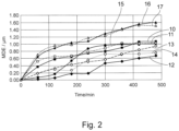
- each sample (D and examples 3 to 5) comprises two sets of results, corresponding to two separate tests of the cavitation erosion resistance as described.
- Grade C is represented by lines 12 and 13.
- Comparative 3 is represented by lines 10 and 11.
- Comparative 4 is represented by lines 14 and 15.
- Comparative 5 is represented by lines 16 and 17.
- the MDE of grade D was the lowest of all MDE tested samples. According, the present cemented carbide material (grade D) exhibited high wear (wet erosion resistance) in combination with enhanced toughness and corrosion resistance.
- any reference to “wt%” refers to the mass fraction of the component relative to the total mass of the cemented carbide.
Landscapes
- Chemical & Material Sciences (AREA)
- Engineering & Computer Science (AREA)
- Mechanical Engineering (AREA)
- Materials Engineering (AREA)
- Metallurgy (AREA)
- Organic Chemistry (AREA)
- Manufacturing & Machinery (AREA)
- Powder Metallurgy (AREA)
- Cutting Tools, Boring Holders, And Turrets (AREA)
Description
- The present subject matter relates to a wear resistant cemented carbide and method of manufacture for high demand applications and in particular although not exclusively to a corrosion and erosion resistance cemented carbide having a relatively high toughness for a given hardness.
- Cemented carbides have been used extensively for high demand applications such as tools for cutting, machining, drilling or degrading rock. These high wear resistant carbides have found particular application as components within the oil and gas industry where they are used typically for a variety of fluid flow control components including for example choke and control valves, cages, valve seats and seal rings. Their suitability is due largely to their physical and mechanical characteristics including in particular hardness, toughness, strength and wear resistance. Within physical high demand oil and gas applications, conventional cemented carbide components have relatively short lifetimes. Additionally, prediction of in-service performance and the liability is critical due to limited accessibility (e.g. subsea environments) and the extensive production down-time for servicing.
- Flow control components within oil and gas production systems are typically subjected to high fluid velocity flows (> 200 m/s) where the fluid is typically mixed sand/oil/gas/water at variable humidity, flow rate and pH. Operating conditions can also include 'sour' conditions that include in particular exposure to H2S with an associated increased likelihood of corrosion, pitting and stepwise cracking.
- The increasing challenging conditions of operation (including specifically high variability of the flow media and the extreme high pressure and high temperature) together with the deep-water environment mean that conventional components have a short service lifetime and are susceptible to high rates of failure.
-
WO 2017/220533 discloses a process line tool of a cemented carbide comprising in wt%: 2.9-11 Ni; 0.1-2.5 Cr3C2; 0.1-1 Mo and WC balance in which the WC comprises a grain size less than or equal to 0.5 µm. -
CN 102400027 describes a corrosion resistant cemented carbide having wt% 7.3-7.7 Ni, 0.6-1 Cr3C2, 0.3-0.7 Mo and balance WC. -
WO 2012/045815 describes a cemented carbide for oil and gas applications exhibiting galvanic corrosion resistance comprising WC and wt%: 3-11 Ni; 0.5-7 Cr; 0.3-1.5 Mo; 0-1 Nb and 0-0.2 Co. -
WO 2016/107842 discloses a cemented carbide for fluid handling components such as a seal ring having a composition in wt% 7-11 Ni; 0.5-2.5 Cr3C2; 0.5-1 Mo and balance WC having a WC grain size greater than or equal to 4 µm. - However, under certain circumstances within oil and gas fluid flow control, existing cemented carbides are not optimised for corrosion and mechanical resistance and in particular wet erosion resistance. That is, existing cemented carbides exhibit an unsatisfactory rate of failure when the flow conditions are corrosive and erosive, in particular in the case of erosion induced by a slurry and/or a cavitation phenomenon.
- The scope of the present invention is defined by
independent claims - The present disclosure is directed to cemented carbide materials suitable for high demand applications and in particular for use as a constituent or primary material for a component part of such high demand applications. Also provided are cemented carbides having desired toughness, hardness, strength and wear resistant properties to withstand challenging environmental and operative conditions.
- Also provided are cemented carbides suitable for use as a tool for metal forming or a wear part for fluid handling.
- Also provided are cemented carbides suitable for use as a component part within oil and gas production including in particular use as a fluid flow component.
- The objectives are achieved by a cemented carbide material having a relatively high hardness, toughness and transverse rupture strength (TRS). The cemented carbide materials according to the present invention comprise a hardness in a range 1550 to 1700 HV30 (ISO 3878:1983). Additionally, the present cemented carbide comprise a toughness in a range 9 to 11 MN/m3/2 (Palmqvist, ISO 28079:2009). Additionally, the present cemented carbides may comprise a TRS of greater than 3000 N/mm2 (ISO 3327:2009).
- There is provided a cemented carbide comprising a hard phase including WC and a binder phase characterised in that: the binder phase content of the cemented carbide is between 7 to 11 wt%; the cemented carbide comprises in wt% 5.9-9 Ni; 0.45-0.75 Cr; 0.55-0.85 Mo and 85-95 or 87-94 WC; and wherein a grain size of the WC is in the range 0.1 to 2 µm determined by linear intercept.
- In the present invention, the cemented carbide comprises WC as balance wt%.
- The present cemented carbide is particularly suited for use as a component and in particular a fluid flow control component having high erosion, abrasion and corrosion resistance and in particular wet erosion resistance. The present cemented carbide is therefore particularly suited for use as a component within oil and gas production. In particular, the inventors have identified that the recited carbide grade provides high cavitation, corrosion and erosion resistance due, in part, to the recited composition and in particular the binder content (relative to hard phase content) and WC grain size. The present cemented carbide provides a component having significantly enhanced slurry erosion resistance and improved cavitation resistance (associated with toughness).
- The cemented carbide comprises Cr, Mo and W in any one or in combination of free/elemental form, or as a compound in combination with any or a combination of the other constituents of the cemented carbide.
- Optionally, there is provided a cemented carbide comprising a hard phase including WC and a binder phase; the binder phase content of the cemented carbide is between 7 to 11 wt%; and the cemented carbide consists of in wt% 5.9-9 Ni; 0.45-0.75 Cr; 0.55-0.85 Mo and if present any one or a combination of Fe, Co, Ti, Nb, Ta, V, Re, Ru, Zr, Al and/or Y at impurity levels; and wherein a grain size of the WC is in the range 0.1 to 2 µm determined by linear intercept.
- Preferably the cemented carbide comprises exclusively carbides. Preferably the cemented carbide comprises WC as a predominant wt% carbide component. Optionally, the cemented carbide may comprise minority wt% carbides of any one or a combination of Mo and Cr.
- Optionally, the cemented carbide is devoid of nitrides and/or carbonitrides. Optionally, the cemented carbide may comprise nitrides and/or carbonitrides present at impurity level. Optionally, the impurity level of such nitrides and/or carbonitrides is less than 0.05, 0.01 or 0.001 wt%. Optionally, the cemented carbide is devoid of Ti and carbides, nitrides and/or carbonitrides of Ti. Preferably, the cemented carbide comprises 0 wt% Ti so as to be compositionally free of Ti.
- Optionally, in some aspects substantially all, a majority or a predominant component in wt% of Ni, Cr and Mo are present within the binder phase. That is, in certain embodiments, a minor or relatively low amount (i.e. wt% less than 10, 5, 2 or 1%) of the total wt% amount of each of Ni, Cr and/or Mo may be present outside/beyond of the binder phase. Such minor amounts may be present at the grain boundaries between the hard phase and the binder phase or within the hard phase.
- Optionally, the hard phase of the cemented carbide is at least 85, 86, 87, 88, 89, 90, 91, 92, 93 wt%. Optionally, the amount of WC in the cemented carbide is at least 85 wt% or 87 wt% or in a range 85 to 95, 87 to 94, 88 to 93 or 89 to 92 wt%.
- Optionally, a carbon content within the sintered cemented carbide is maintained within a predetermined range to further contribute to the high wet erosion resistance, wear resistance and toughness. Optionally, the carbon content of the sintered material may be held in a range between free carbon in the micro structure (upper limit) and a point of eta-phase initiation (lower limit). Such limits will be appreciated by those skilled in the art.
- Optionally, a quotient wt% Cr/(Ni+Cr+Mo) in the cemented carbide is in a range 0.03 to 0.1; 0.04 to 0.1; 0.05 to 0.1; 0.06 to 0.1 or 0.07 to 0.09. This relative amount of Cr enhances the corrosion and wet erosion resistance while maintaining the desired mechanical properties including hardness and toughness required for the high demand applications such as oil and gas.
- In the present invention, a quotient wt% Mo/(Ni+Cr+Mo) in the cemented carbide is in a range 0.04 to 0.12; optionally 0.04 to 0.1; 0.05 to 0.1; 0.06 to 0.1 or 0.07 to 0.09. The concentration of Mo within the cemented carbide enhances the corrosion and wet erosion resistance whilst maintaining the desired mechanical properties including hardness and toughness required for the mechanically demanding applications.
- The amount (wt%) of binder phase relative to the WC hard phase has been found to enhance toughness whilst maintaining hardness to an appropriate level for high demand applications. The relative binder content also provides a contribution to the enhanced corrosion resistance and in particular wet erosion resistance. Optionally, the cemented carbide may comprise a binder phase at wt% 7.0 to 11.0; 7.5 to 10.5; 8.0 to 10.5; 8.5 to 10 or 8 to 10.
- Optionally, a grain size of the WC within the final, sintered cemented carbide may be in the range 0.1 to 2 µm; 0.2 to 1.8 µm; 0.2 to 1.6; 0.2 to 1.4; 0.2 to 1.2; 0.2 to 1.0; 0.3 to 0.9; 0.4 to 0.8; or 0.5 to 0.7 µm as determined by linear intercept. Optionally, a FSSS grain size of the starting WC material may be in the range 0.4 to 2 µm or 0.5 to 1.5 µm. Such grain sizes provide enhanced toughness whilst maintaining hardness and configure the cemented carbide with enhanced capability to withstand sheer forces and stress. Preferably, the grain size of the WC within the sintered material measured by linear intercept is in the range 0.3 to 0.9 µm.
- In the present invention, the cemented carbide comprises Ni in a range wt% 7.4 to 7.6. In the present invention, the cemented carbide comprises Cr in a range wt% 0.63 to 0.67,
- In the present invention, the cemented carbide comprises Mo in a range wt% 0.73 to 0.77. The recited composition ranges including specifically the amount of Ni, Cr and Mo in addition to the binder content and WC grain size provides a composition exhibiting particularly high wet erosion resistance commonly encountered for components within oil and gas applications. Accordingly, the present cemented carbide is particularly suited for use as a component comprising any one of a choke valve, a control valve, a valve seat, a plug seat, a frac seat, a cage, a cage assembly, a seal ring, a component part of a valve to allow the through-flow of a fluid and/or a slurry. According to one aspect, the present cemented carbide may be used as a tool for metal forming including in particular use as a die, an ironing die, a die for wire drawing or other component within metal forming.
- There is provided a cemented carbide comprising a hard phase including WC and a binder phase characterised in that: the binder phase content of the cemented carbide is between 7 to 11 wt%; the cemented carbide comprises in wt% 5.9-9 Ni; 0.45-0.75 Cr; 0.55-0.85 Mo and WC as balance; and wherein a grain size of the WC is in the range 0.1 to 2 µm determined by linear intercept.
- There is also provided a method of making a cemented carbide article comprising a hard phase including WC and a binder phase, the method comprising and characterised by: preparing a powdered batch comprising raw materials in wt% 6-9 Ni; 0.45-0.75 Cr; 0.55-0.85 Mo and WC included as balance; pressing the powdered batch to form a pre-form; and sintering the pre-form to form the article; wherein the binder phase content of the cemented carbide is between 7 to 11 wt% and a particle size of the WC included as a starting material within the powdered batch is in the range 0.4 to 2 µm determined by FSSS.
- There is also provided a method of making a cemented carbide article comprising a hard phase including WC and a binder phase, the method comprising and characterised by: preparing a powdered batch comprising raw materials in wt% 6-9 Ni; 0.45-0.75 Cr; 0.55-0.85 Mo and 85-95 WC; pressing the powdered batch to form a pre-form; and sintering the pre-form to form the article; wherein the binder phase content of the cemented carbide is between 7 to 11 wt% and a particle size of the WC included as a starting material within the powdered batch is in the range 0.4 to 2 µm determined by FSSS.
- Optionally, the step of sintering the pre-form to form the article comprises vacuum or HIP processing. Optionally, the sintering processing comprises processing at a temperature 1360-1500°C and a pressure 0-20 MPa.
- There is also provided an article for high demand applications manufactured by the method as described herein.
- There is also provided a cemented carbide article obtainable by the method as described herein.
- Optionally, the Cr may be added to part of the powdered batch in the form Cr3C2.
- Optionally, the method may comprise adding elemental Cr. According to such implementations, the method may further comprise adding additional carbon so as to achieve the desired wt% carbon within the sintered cemented carbide in a range between free carbon in the microstructure (upper limit) and eta-phase initiation (lower limit) as will be appreciated by those skilled in the art. Optionally, the FSSS WC particle size within the powdered batch may be in the range 0.4 to 2 µm; 0.6 to 1.8; 0.8 to 1.6; 0.8 to 1.4; or 0.8 to 1.2.
- Optionally, the present cemented carbide is a tungsten cemented carbide.
- The present cemented carbide may further comprise carbides, nitrides and/or carbonitrides selected from the group of tungsten, titanium, chromium, vanadium, tantalum, neodymium, niobium and molybdenum. Such components may be added to the powder batch as minor wt% additives relative to WC that preferably is included within the cemented carbide as a majority or predominant wt% component relative to other components of the material.
- Optionally the cemented carbide may comprise metallic phase components including iron, chromium, nickel, cobalt, molybdenum or combinations thereof. Such components may be present within the binder phase. Preferably the present cemented carbide is devoid of cobalt (i.e., comprises zero or near zero wt% cobalt) so as to be compositionally free of Co. Optionally the cemented carbide may comprise cobalt at impurity levels being of the order of less than 0.01, 0.05, 0.01 or 0.001 wt%.
- Optionally, the cemented carbide is devoid of nitrogen or nitrogen compounds. However, the cemented carbide may comprise nitrogen or nitrogen compounds such as nitrides at impurity level such as less than 0.1wt%, 0.05wt% or 0.01wt%.
- Optionally, the present cemented carbide may further include any of Fe, Ti, Nb, Ta, V, Re, Ru, Zr, Al and/or Y at impurity levels. These elements may be present either in elemental, carbide, nitride or carbonitride form. The impurity level is a level such as less than 0.1wt% or 0.5wt% for the total amount of impurities present within the cemented carbide
- A specific implementation of the present invention will now be described, by way of example only, and with reference to the accompanying drawings in which:
-
Figure 1 is a graph of volume of material loss due to slurry erosion (mm3) for different example materials according to aspects of the present invention in addition to comparative examples; -
Figure 2 is a graph of wear induced by cavitation over time for different example materials according to aspects of the present invention in addition to comparative examples. - A wear resistant cemented carbide grade is provided with relative high toughness and exhibiting enhanced corrosion and erosion resistance. The inventors have identified that such physical and mechanical characteristics may be achieved via a binder phase content relative to a WC hard phase of in the range 7 to 11 wt% and in which the cemented carbide has a wt% composition 5.9-9 Ni; 0.45-0.75 Cr; 0.55-0.85 Mo and WC included as balance. The desired physical and mechanical characteristics are also achieved by controlling the grain size of WC as determined by Fisher Model 95 Sub-Sieve Sizer™ (FSSS) in the range 0.1 to 2 µm and preferably 0.2 to 1 µm. In particular, the inventors identify that the grain size of these sintered cemented carbide provides enhanced wet erosion resistance as would typically be encountered by a fluid flow control component exposed to a slurry as typically encountered within oil and gas applications.
- The present cemented carbide is specifically adapted for potential high wear and high demand applications including use as a component within oil and gas production with such components being susceptible to corrosion and mechanical erosion (including in particular wet erosion). The present carbide is also suitable for the use as a tool for metal forming or as a wear part for fluid handling.
- Conventional powder metallurgical methods including milling, pressing, shaping and sinter hipping were used to manufacture a cemented carbide according to the present invention. Cemented carbide materials according to the present invention were prepared in addition to comparative test coupons.
- Each of the sample mixtures Grades A to G were prepared from powders forming the hard constituents and powders forming the binder. The following preparation method corresponds to Grade E of Table 1 below having starting powdered materials: WC 95.05g, Cr3C2 0.61 g, Ni 6.89 g, C 0.07 g, Mo 0.61 g, PEG 2 g, Ethanol 50 ml. It will be appreciated by those skilled in the art that it is the relative amounts of the powdered materials that allow the skilled person and suitable adjustment is needed to make the powdered batch and achieve the final fully sintered composition of the cemented carbides of Table 1.The powders were wet milled together with lubricant and anti-flocculating agent until a homogeneous mixture was obtained and granulated by drying and sieving. The dried powder was pressed to form a green part according to the abovementioned standard shapes and sintered using SinterHIP at 1350-1500°C and 5 MPa.
- Table 1 details composition (wt%) together with additional characterisations of grades A to G. Grades C and D are inventive grades, while Grades A, B and E-G are reference grades.
Table 1 - Example grade material compositions A to G according to the present invention. Composition, wt% Grade WC Cr3C2 Ni Mo Total binder WC Raw Material µm Cr3C2/ Binder Tot Mo/ Binder Tot A 89.30 0.85 9.00 0.85 10.70 0.8 0.08 0.08 B 89.30 0.85 9.00 0.85 10.70 0.4 0.08 0.08 C 91.00 0.75 7.50 0.75 9.00 0.8 0.08 0.08 D 91.00 0.75 7.50 0.75 9.00 1 0.08 0.08 E 92.00 0.60 6.80 0.60 8.00 1 0.08 0.08 F 93.00 0.55 5.90 0.55 7.00 1 0.08 0.08 G 93.00 0.55 5.90 0.55 7.00 2 0.08 0.08 - Hardness tests were carried out on grades A to G in accordance with ISO 3878 and toughness testing according to Palmqvist, ISO 28079. Vickers indentation test was performed using 30kgf (HV30) to assess hardness. Palmqvist fracture toughness was calculated according to:

- Where A is a constant of 0.0028, HV is the Vickers hardness in N/mm2, P is the applied load (N) and Σ L is the sum of crack lengths (mm) of the imprint. The results are shown in table 2.
Table 2 - Hardness and toughness tests for sample grades A to G. Grade HV30 KIC A 1581 9.4 B 1622 9.3 C 1683 9.3 D 1587 9.7 E 1591 9.6 F 1664 9.5 G 1593 9.2 - Table 3 details example grade D together with comparative examples 1 to 6 according to various different compositions and WC starting material particle sizes. It will be appreciated the particle size of the starting material is reduced according to standard milling and sintering procedures such that the grain size of the final fully sintered material (determined by linear intercept) may be less than (up to or approximately half) the particle size of the starting material (determined by FSSS).
- The linear intercept method (ISO 4499-2:2008) is a method of measurement of WC grain size. Grain-size measurements are obtained from SEM images of the microstructure. For a nominally two-phase material such as a cemented carbide (hard phase and binder phase), the linear-intercept technique gives information of the grain-size distribution. A line is drawn across a calibrated image of the microstructure of the cemented carbide. Where this line intercepts a grain of WC, the length of the line (li ) is measured using a calibrated rule (where i=1,2,3,...n for the first 1st, 2nd, 3rd,...,nth grain). At least 100 grains where counted for the measurements. The average WC grain size will be defined as:

Table 3 - Compositions of example grade D with various comparative examples 1 to 6. Grade WC (TiC, TaC, NbC) Co Cr3C2 Ni Mo WC Raw Material, µm D 91 0 0 0.75 7.50 0.75 1 Comparative 190.9 0 0 0.80 8.02 0.28 5 Comparative 2 89.81 0 0 0.80 8.49 0.80 8 Comparative 388.6 0 0 0.90 9.60 0.9 0.8 Comparative 4 87.8 0 3.5 1.5 7 0.2 0.8 Comparative 5 94.9 0 3.3 0.6 1.1 0.1 0.8 Comparative 6 88 5 1.2 1.2 3.6 0 2 - Hardness (ISO 3878), toughness (Palmqvist, ISO 28079) and TRS (ISO 3327:2009) tests were undertaken on grade D, as well as comparative examples 1 to 6. The test pieces for transverse rupture strength's determination were cylinders of Type C (cylindrical cross-section with 40x3 mm2 dimension). The samples were placed between two supports and loaded in their center until fracture occurred (3-points bending). The maximum load was recorded and averaged over minimum five samples per test. The results are shown in table 4.
Table 4 - Physical and mechanical performance test results of grade D and comparative examples 1 to 6. Grade HV30 KIC TRS D 1587 9.7 4050 Comparative 11344 13.8 3900 Comparative 2 1210 12.2 3025 Comparative 31550 9.5 4550 Comparative 41540 10.3 3300 Comparative 51904 8.8 3800 Comparative 61934 8.7 2275 - The corrosion rate of grade D and comparative examples 1, 3, 4, 5 and 6 was assessed and the results are shown in table 5. The surface roughness (Ra) of the samples was 0.036 µm. The corrosion rate in mm/year was estimated by means of mass loss against time of immersion under the following simulated test conditions:
- 1) Immersion for 212h in synthetic sea water at pH 6 (3.56%wt. NaCl) at 25°C, in aerated conditions.
- 2) Immersion for 212h in synthetic sea water at pH 1 (3.56%wt. NaCl + 0.1M H2SO4) at 60°C, in aerated conditions.
- The mass loss corrosion rate in mm/year was estimated according to the above simulated conditions using the formula (ASTM G31 - 72 'Standard Practice for Laboratory Immersion Corrosion Testing of Metals'):

Table 5 - Corrosion immersion testing results for grades D and comparative examples 1, 3, 4, 5 and 6. Grade Material loss (mm/year) in synthetic seawater at pH6, and 25°C Material loss (mm/year) in synthetic seawater at pH1, and 60°C D 0.51 × 10⁻³ ± 0.14 × 10⁻³ 69.28 × 10⁻³ ± 0.46 × 10⁻³ Comparative 14.11 × 10⁻³ ± 0.68 × 10⁻³ 72.31 × 10⁻³ ± 1.08 × 10⁻³ Comparative 33.46 × 10⁻³ ± 0.34 × 10⁻³ 55.34 × 10⁻³ ± 0.96 × 10⁻³ Comparative 44.14 × 10⁻³ ± 0.69 × 10⁻³ 105.52 × 10⁻³ ± 12.03 × 10⁻³ Comparative 51.94 × 10⁻³ ± 0.96 × 10⁻³ 94.05 × 10⁻³ ± 3.65 × 10⁻³ Comparative 63.28 × 10⁻³ ± 1.36 × 10⁻³ 68.31 × 10⁻³ ± 5.99 × 10⁻³ - The corrosion resistance of grade D together with comparative example 1, 3, 4, 5 and 6 was tested by means of polarization (potentiodymamic) curves in synthetic sea water at pH 1 (3.56%wt. NaCl) at 25°C in aerated conditions. The surface roughness (Ra) of the samples was 0.017µm. Firstly, the open circuit potential (OCP) was recorded for 1h, secondly the polarization resistance was estimated by applying a potential to the sample from -5 mV to +5 mV around the OCP at a scanning rate of 0.166 mV/s, finally a cyclic polarization was applied to the sample at 0.5mV/s, from the OCP in the anodic direction to a maximum current of 5 mA/cm2, then reversed. The results are shown in Table 6.
Table 6 - Corrosion resistance: OCP, breakdown or pitting potential, repassivation potential and polarization resistance of grade D and comparative examples 1, 3, 4, 5 and 6. Grade OCP after 1 h (mV/Ag/AgCl) Breakdown or pitting potential (mV/Ag/AgCl) Repassivation potential(mV/Ag /AgCl) Polarization resistance (Ω.cm2) D -180 860 N/A 2051 ± 307 Comparative 1 -160 860 N/A 1743 ± 363 Comparative 3 -130 565 110 1044 ± 129 Comparative 4 -170 790 N/A 1223 ± 272 Comparative 5 -145 -90 none 809 ± 157 Comparative 6 -130 860 N/A 2687± 239 - Wet (slurry) erosion resistance of the grades of table 3 was tested using a wet slurry erosion rig under the following conditions:
- 3.5% NaCl simulated sea-water slurry solution
- Erodent size: ~181-250 µm
- slurry flow rate of ~ 41 L/min;
- jet flow velocity of ~ 24 m/s;
- slurry concentration of ~ 2.1 %wt/wt
- 120 minutes running time
- 30° angle
- The results are shown in
figure 1 which is a graph of volume of material loss during slurry erosion testing according to the above conditions. As will be noted, grade C exhibited the lowest volume loss relative to all the comparative examples tested. - The cavitation erosion resistance of grade D and comparative examples 3 to 5 were tested in 3.5% NaCl solution at 25 °C following ASTM G 32 - 7 ('Standard test method for cavitation erosion using vibratory apparatus'). The results are shown in
figure 2 which is a graph of normalized cumulative mean depth of erosion (MDE) vs time/min of exposure to the cavitation horn. As will be noted, each sample (D and examples 3 to 5) comprises two sets of results, corresponding to two separate tests of the cavitation erosion resistance as described. Grade C is represented bylines lines lines lines - Unless defined otherwise all technical and scientific terms used herein have the same meaning as commonly understood to one of ordinary skill in the art to which the presently described subject matter pertains.
- Unless otherwise indicated, any reference to "wt%" refers to the mass fraction of the component relative to the total mass of the cemented carbide.
- Where a range of values is provided, for example, concentration ranges, percentage range or ratio ranges, it is understood that each intervening value, to the tenth of the unit of the lower limit, unless the context clearly dictates otherwise, between the upper and lower limit of that range and any other stated or intervening value in that stated range, is encompassed within the described subject matter. The upper and lower limits of these smaller ranges may independently be included in the smaller ranges, and such embodiments are also encompassed within the described subject matter, subject to any specifically excluded limit in the stated range. Where the stated range includes one or both of the limits, ranges excluding either or both of those included limits are also included in the described subject matter.
- It should be understood that the terms "a" and "an" as used above and elsewhere herein refer to "one or more" of the enumerated components. It will be clear to one of ordinary skill in the art that the use of the singular includes the plural unless specifically stated otherwise. Therefore, the terms "a", "an" and "at least one" are used interchangeably in this application.
- Unless otherwise indicated, all numbers expressing quantities of ingredients, properties such as size, weight, reaction conditions and so forth used in the specification and claims are to be understood as being modified in all instances by the term "about". Accordingly, unless indicated to the contrary, the numerical parameters set forth in the following specification and attached claims are approximations that may vary depending upon the desired properties sought to be obtained by the present subject matter. At the very least, and not as an attempt to limit the application of the doctrine of equivalents to the scope of the claims, each numerical parameter should at least be construed in light of the number of reported significant digits and by applying ordinary rounding techniques.
- Throughout the application, descriptions of various embodiments use "comprising" language; however, it will be understood by one of skill in the art that, in some instances, an embodiment can alternatively be described using the language "consisting essentially of" or "consisting of".
- It should be noted that the embodiments of the present disclosure is for the explanation of the present disclosure, and not for the limitation of the present invention. The scope of the present invention is defined in the appended claims.
Claims (8)
- A cemented carbide comprising a hard phase including WC and a binder phase, wherein,the binder phase content of the cemented carbide is between 7 to 11 wt%; the cemented carbide comprises in wt% 7.4-7.6 Ni; 0.45-0.75 Cr; 0.73-0.77 Mo; optionally the cemented carbide being:devoid of cobalt so as to be compositionally free of Co or comprising cobalt at impurity levels being less than 0.05, 0.01 or 0.001 wt%, anddevoid of nitrogen or nitrogen compounds or comprising nitrogen or nitrogen compounds such as nitrides at impurity level being less than 0.1wt%, 0.05wt% or 0.01wt%;a quotient wt% Mo/(Ni+Cr+Mo) in the cemented carbide is in a range 0.04 to 0.12;wherein cemented carbide comprises a balance of WC in wt% of 85-95 WC,a grain size of the WC is in the range 0.1 to 2 µm determined by linear intercept; andthe cemented carbide comprises a hardness in a range 1550 to 1700 HV30 according to ISO 3878:1983 and a toughness in a range 9 to 11 MN/m3/2 according to Palmqvist, ISO 28079:2009.
- The cemented carbide as claimed in claim 1 including the binder phase at wt% 8.0 to 10.0.
- The cemented carbide as claimed in claims 1 or 2 wherein the grain size of WC is in the range 0.2 to 1.0 µm determined by linear intercept.
- The cemented carbide as claimed in claim 3 wherein a grain size of the WC is a range 0.3 to 0.9 µm or 0.4 to 0.8 µm determined by linear intercept.
- A component comprising the cemented carbide as claimed in any preceding claim, being any one of: a choke valve, a control valve, a valve seat, a plug seat, a frac seat, a cage, a cage assembly, a seal ring, a component part of a valve to allow the through-flow of a fluid and/or a slurry.
- A method of making a cemented carbide article comprising a hard phase including WC and a binder phase, the method comprising:preparing a powdered batch comprising raw materials in wt% 7.4-7.6 Ni; 0.45-0.75 Cr; 0.73-0.77 Mo and a balance of 85-95 WC;pressing the powdered batch to form a pre-form; andsintering the pre-form to form the article;wherein the binder phase content of the cemented carbide is between 7 to 11 wt% and a particle size of the WC included as a starting material within the powdered batch is in the range 0.1 to 2 µm determined by FSSS;wherein optionally the cemented carbide is:devoid of cobalt so as to be compositionally free of Co or comprising cobalt at impurity levels being less than 0.05, 0.01 or 0.001 wt%, anddevoid of nitrogen or nitrogen compounds or comprising nitrogen or nitrogen compounds such as nitrides at impurity level being less than 0.1wt%, 0.05wt% or 0.01wt%;a quotient wt% Mo/(Ni+Cr+Mo) in the cemented carbide is in a range 0.04 to 0.12;wherein the cemented carbide comprises a hardness in a range 1550 to 1700 HV30 according to ISO 3878:1983 and a toughness in a range 9 to 11 MN/m3/2 according to Palmqvist, ISO 28079:2009.
- The method as claimed in claim 6 wherein the step of sintering the pre-form to form the article comprises vacuum or HIP processing.
- The method as claimed in claims 6 or 7 wherein the sintering processing comprises processing at a temperature 1360-1500°C and a pressure 0-20 MPa.
Applications Claiming Priority (2)
| Application Number | Priority Date | Filing Date | Title |
|---|---|---|---|
| GBGB1820632.6A GB201820632D0 (en) | 2018-12-18 | 2018-12-18 | Cemented carbide for high demand applications |
| PCT/IB2019/060285 WO2020128688A1 (en) | 2018-12-18 | 2019-11-28 | Cemented carbide for high demand applications |
Publications (2)
| Publication Number | Publication Date |
|---|---|
| EP3899077A1 EP3899077A1 (en) | 2021-10-27 |
| EP3899077B1 true EP3899077B1 (en) | 2025-06-04 |
Family
ID=65147050
Family Applications (1)
| Application Number | Title | Priority Date | Filing Date |
|---|---|---|---|
| EP19816463.4A Active EP3899077B1 (en) | 2018-12-18 | 2019-11-28 | Cemented carbide for high demand applications, and method of manufacturing thereof |
Country Status (9)
| Country | Link |
|---|---|
| US (1) | US11655525B2 (en) |
| EP (1) | EP3899077B1 (en) |
| JP (1) | JP7483712B2 (en) |
| KR (1) | KR102849727B1 (en) |
| CN (1) | CN113166861A (en) |
| ES (1) | ES3033934T3 (en) |
| GB (1) | GB201820632D0 (en) |
| PT (1) | PT3899077T (en) |
| WO (1) | WO2020128688A1 (en) |
Family Cites Families (10)
| Publication number | Priority date | Publication date | Assignee | Title |
|---|---|---|---|---|
| FR2097258A5 (en) | 1970-06-18 | 1972-03-03 | Ugine Carbone | |
| SE420844B (en) | 1979-05-17 | 1981-11-02 | Sandvik Ab | SINTRAD HARD METAL OF NICKEL-BASED BINDING METAL AND VOLFORCARBID |
| AT385775B (en) * | 1985-08-08 | 1988-05-10 | Plansee Metallwerk | CORROSION-RESISTANT CARBIDE ALLOY |
| US5736658A (en) * | 1994-09-30 | 1998-04-07 | Valenite Inc. | Low density, nonmagnetic and corrosion resistant cemented carbides |
| JP5195274B2 (en) | 2008-10-22 | 2013-05-08 | 新日鐵住金株式会社 | Abrasion resistant screen and method of manufacturing the same |
| CN101892411B (en) * | 2010-08-09 | 2013-01-16 | 中国地质大学(北京) | Novel WC-based hard alloy material and preparation method thereof |
| EP2439300A1 (en) * | 2010-10-08 | 2012-04-11 | Sandvik Intellectual Property AB | Cemented carbide |
| CN102400027A (en) | 2011-10-21 | 2012-04-04 | 四川科力特硬质合金股份有限公司 | Seawater corrosion resistant hard alloy and preparation method thereof |
| MX2017008636A (en) | 2014-12-30 | 2017-10-11 | Sandvik Intellectual Property | Corrosion resistant cemented carbide for fluid handling. |
| PL3475458T3 (en) * | 2016-06-23 | 2020-07-27 | Hyperion Materials & Technologies (Sweden) Ab | Corrosion and fatigue resistant cemented carbide process line tool |
-
2018
- 2018-12-18 GB GBGB1820632.6A patent/GB201820632D0/en not_active Ceased
-
2019
- 2019-11-28 KR KR1020217017430A patent/KR102849727B1/en active Active
- 2019-11-28 CN CN201980079210.5A patent/CN113166861A/en active Pending
- 2019-11-28 JP JP2021534296A patent/JP7483712B2/en active Active
- 2019-11-28 US US17/291,057 patent/US11655525B2/en active Active
- 2019-11-28 WO PCT/IB2019/060285 patent/WO2020128688A1/en not_active Ceased
- 2019-11-28 PT PT198164634T patent/PT3899077T/en unknown
- 2019-11-28 ES ES19816463T patent/ES3033934T3/en active Active
- 2019-11-28 EP EP19816463.4A patent/EP3899077B1/en active Active
Also Published As
| Publication number | Publication date |
|---|---|
| PT3899077T (en) | 2025-09-11 |
| GB201820632D0 (en) | 2019-01-30 |
| CN113166861A (en) | 2021-07-23 |
| KR20210102894A (en) | 2021-08-20 |
| JP7483712B2 (en) | 2024-05-15 |
| WO2020128688A1 (en) | 2020-06-25 |
| ES3033934T3 (en) | 2025-08-11 |
| KR102849727B1 (en) | 2025-08-22 |
| US11655525B2 (en) | 2023-05-23 |
| JP2022513901A (en) | 2022-02-09 |
| EP3899077A1 (en) | 2021-10-27 |
| US20210388472A1 (en) | 2021-12-16 |
Similar Documents
| Publication | Publication Date | Title |
|---|---|---|
| US7678327B2 (en) | Cemented carbide tools for mining and construction applications and method of making same | |
| EP2778242B1 (en) | Cemented carbide | |
| CN117120183A (en) | cutting tools | |
| EP3899078B1 (en) | Cemented carbide for high demand applications | |
| EP1099001B1 (en) | Use of a cemented carbide for oil and gas applications | |
| EP1413637B1 (en) | Cemented carbide with improved toughness for oil and gas applications | |
| US11655525B2 (en) | Cemented carbide for high demand applications | |
| WO2015092528A1 (en) | Composition for a novel grade for cutting tools | |
| EP3240916B1 (en) | Light weight cemented carbide for flow erosion components | |
| MXPA00012832A (en) | Cemented carbide for oil and gas applications |
Legal Events
| Date | Code | Title | Description |
|---|---|---|---|
| STAA | Information on the status of an ep patent application or granted ep patent |
Free format text: STATUS: UNKNOWN |
|
| STAA | Information on the status of an ep patent application or granted ep patent |
Free format text: STATUS: THE INTERNATIONAL PUBLICATION HAS BEEN MADE |
|
| PUAI | Public reference made under article 153(3) epc to a published international application that has entered the european phase |
Free format text: ORIGINAL CODE: 0009012 |
|
| STAA | Information on the status of an ep patent application or granted ep patent |
Free format text: STATUS: REQUEST FOR EXAMINATION WAS MADE |
|
| 17P | Request for examination filed |
Effective date: 20210504 |
|
| AK | Designated contracting states |
Kind code of ref document: A1 Designated state(s): AL AT BE BG CH CY CZ DE DK EE ES FI FR GB GR HR HU IE IS IT LI LT LU LV MC MK MT NL NO PL PT RO RS SE SI SK SM TR |
|
| DAV | Request for validation of the european patent (deleted) | ||
| DAX | Request for extension of the european patent (deleted) | ||
| STAA | Information on the status of an ep patent application or granted ep patent |
Free format text: STATUS: EXAMINATION IS IN PROGRESS |
|
| 17Q | First examination report despatched |
Effective date: 20230102 |
|
| P01 | Opt-out of the competence of the unified patent court (upc) registered |
Effective date: 20230703 |
|
| RAP3 | Party data changed (applicant data changed or rights of an application transferred) |
Owner name: HYPERION MATERIALS & TECHNOLOGIES (SWEDEN) AB |
|
| GRAP | Despatch of communication of intention to grant a patent |
Free format text: ORIGINAL CODE: EPIDOSNIGR1 |
|
| STAA | Information on the status of an ep patent application or granted ep patent |
Free format text: STATUS: GRANT OF PATENT IS INTENDED |
|
| RIC1 | Information provided on ipc code assigned before grant |
Ipc: C22C 1/05 20060101ALN20241209BHEP Ipc: B22F 3/15 20060101ALN20241209BHEP Ipc: B22F 5/00 20060101ALN20241209BHEP Ipc: C22C 29/08 20060101ALI20241209BHEP Ipc: C22C 29/06 20060101ALI20241209BHEP Ipc: C22C 29/00 20060101AFI20241209BHEP |
|
| INTG | Intention to grant announced |
Effective date: 20250107 |
|
| GRAS | Grant fee paid |
Free format text: ORIGINAL CODE: EPIDOSNIGR3 |
|
| GRAA | (expected) grant |
Free format text: ORIGINAL CODE: 0009210 |
|
| STAA | Information on the status of an ep patent application or granted ep patent |
Free format text: STATUS: THE PATENT HAS BEEN GRANTED |
|
| AK | Designated contracting states |
Kind code of ref document: B1 Designated state(s): AL AT BE BG CH CY CZ DE DK EE ES FI FR GB GR HR HU IE IS IT LI LT LU LV MC MK MT NL NO PL PT RO RS SE SI SK SM TR |
|
| REG | Reference to a national code |
Ref country code: GB Ref legal event code: FG4D |
|
| REG | Reference to a national code |
Ref country code: CH Ref legal event code: EP |
|
| REG | Reference to a national code |
Ref country code: DE Ref legal event code: R096 Ref document number: 602019070828 Country of ref document: DE |
|
| REG | Reference to a national code |
Ref country code: IE Ref legal event code: FG4D |
|
| REG | Reference to a national code |
Ref country code: ES Ref legal event code: FG2A Ref document number: 3033934 Country of ref document: ES Kind code of ref document: T3 Effective date: 20250811 |
|
| REG | Reference to a national code |
Ref country code: NL Ref legal event code: FP |
|
| REG | Reference to a national code |
Ref country code: PT Ref legal event code: SC4A Ref document number: 3899077 Country of ref document: PT Date of ref document: 20250911 Kind code of ref document: T Free format text: AVAILABILITY OF NATIONAL TRANSLATION Effective date: 20250903 |
|
| PG25 | Lapsed in a contracting state [announced via postgrant information from national office to epo] |
Ref country code: FI Free format text: LAPSE BECAUSE OF FAILURE TO SUBMIT A TRANSLATION OF THE DESCRIPTION OR TO PAY THE FEE WITHIN THE PRESCRIBED TIME-LIMIT Effective date: 20250604 |
|
| REG | Reference to a national code |
Ref country code: LT Ref legal event code: MG9D |
|
| PG25 | Lapsed in a contracting state [announced via postgrant information from national office to epo] |
Ref country code: GR Free format text: LAPSE BECAUSE OF FAILURE TO SUBMIT A TRANSLATION OF THE DESCRIPTION OR TO PAY THE FEE WITHIN THE PRESCRIBED TIME-LIMIT Effective date: 20250905 |
|
| PG25 | Lapsed in a contracting state [announced via postgrant information from national office to epo] |
Ref country code: PL Free format text: LAPSE BECAUSE OF FAILURE TO SUBMIT A TRANSLATION OF THE DESCRIPTION OR TO PAY THE FEE WITHIN THE PRESCRIBED TIME-LIMIT Effective date: 20250604 |
|
| PG25 | Lapsed in a contracting state [announced via postgrant information from national office to epo] |
Ref country code: BG Free format text: LAPSE BECAUSE OF FAILURE TO SUBMIT A TRANSLATION OF THE DESCRIPTION OR TO PAY THE FEE WITHIN THE PRESCRIBED TIME-LIMIT Effective date: 20250604 |
|
| PG25 | Lapsed in a contracting state [announced via postgrant information from national office to epo] |
Ref country code: HR Free format text: LAPSE BECAUSE OF FAILURE TO SUBMIT A TRANSLATION OF THE DESCRIPTION OR TO PAY THE FEE WITHIN THE PRESCRIBED TIME-LIMIT Effective date: 20250604 |
|
| PG25 | Lapsed in a contracting state [announced via postgrant information from national office to epo] |
Ref country code: RS Free format text: LAPSE BECAUSE OF FAILURE TO SUBMIT A TRANSLATION OF THE DESCRIPTION OR TO PAY THE FEE WITHIN THE PRESCRIBED TIME-LIMIT Effective date: 20250904 |
|
| PG25 | Lapsed in a contracting state [announced via postgrant information from national office to epo] |
Ref country code: LV Free format text: LAPSE BECAUSE OF FAILURE TO SUBMIT A TRANSLATION OF THE DESCRIPTION OR TO PAY THE FEE WITHIN THE PRESCRIBED TIME-LIMIT Effective date: 20250604 |
|
| PGFP | Annual fee paid to national office [announced via postgrant information from national office to epo] |
Ref country code: PT Payment date: 20251110 Year of fee payment: 7 |
|
| PGFP | Annual fee paid to national office [announced via postgrant information from national office to epo] |
Ref country code: NL Payment date: 20251126 Year of fee payment: 7 |
|
| REG | Reference to a national code |
Ref country code: AT Ref legal event code: MK05 Ref document number: 1800391 Country of ref document: AT Kind code of ref document: T Effective date: 20250604 |
|
| PG25 | Lapsed in a contracting state [announced via postgrant information from national office to epo] |
Ref country code: IS Free format text: LAPSE BECAUSE OF FAILURE TO SUBMIT A TRANSLATION OF THE DESCRIPTION OR TO PAY THE FEE WITHIN THE PRESCRIBED TIME-LIMIT Effective date: 20251004 |
|
| PGFP | Annual fee paid to national office [announced via postgrant information from national office to epo] |
Ref country code: DE Payment date: 20251128 Year of fee payment: 7 |
|
| PGFP | Annual fee paid to national office [announced via postgrant information from national office to epo] |
Ref country code: GB Payment date: 20251127 Year of fee payment: 7 |
|
| PGFP | Annual fee paid to national office [announced via postgrant information from national office to epo] |
Ref country code: NO Payment date: 20251128 Year of fee payment: 7 |
|
| PG25 | Lapsed in a contracting state [announced via postgrant information from national office to epo] |
Ref country code: AT Free format text: LAPSE BECAUSE OF FAILURE TO SUBMIT A TRANSLATION OF THE DESCRIPTION OR TO PAY THE FEE WITHIN THE PRESCRIBED TIME-LIMIT Effective date: 20250604 Ref country code: SM Free format text: LAPSE BECAUSE OF FAILURE TO SUBMIT A TRANSLATION OF THE DESCRIPTION OR TO PAY THE FEE WITHIN THE PRESCRIBED TIME-LIMIT Effective date: 20250604 |
|
| PGFP | Annual fee paid to national office [announced via postgrant information from national office to epo] |
Ref country code: FR Payment date: 20251125 Year of fee payment: 7 |
|
| PG25 | Lapsed in a contracting state [announced via postgrant information from national office to epo] |
Ref country code: CZ Free format text: LAPSE BECAUSE OF FAILURE TO SUBMIT A TRANSLATION OF THE DESCRIPTION OR TO PAY THE FEE WITHIN THE PRESCRIBED TIME-LIMIT Effective date: 20250604 |
|
| PGFP | Annual fee paid to national office [announced via postgrant information from national office to epo] |
Ref country code: IE Payment date: 20251127 Year of fee payment: 7 |
|
| PG25 | Lapsed in a contracting state [announced via postgrant information from national office to epo] |
Ref country code: EE Free format text: LAPSE BECAUSE OF FAILURE TO SUBMIT A TRANSLATION OF THE DESCRIPTION OR TO PAY THE FEE WITHIN THE PRESCRIBED TIME-LIMIT Effective date: 20250604 |
|
| PG25 | Lapsed in a contracting state [announced via postgrant information from national office to epo] |
Ref country code: SK Free format text: LAPSE BECAUSE OF FAILURE TO SUBMIT A TRANSLATION OF THE DESCRIPTION OR TO PAY THE FEE WITHIN THE PRESCRIBED TIME-LIMIT Effective date: 20250604 Ref country code: RO Free format text: LAPSE BECAUSE OF FAILURE TO SUBMIT A TRANSLATION OF THE DESCRIPTION OR TO PAY THE FEE WITHIN THE PRESCRIBED TIME-LIMIT Effective date: 20250604 |
|
| PG25 | Lapsed in a contracting state [announced via postgrant information from national office to epo] |
Ref country code: IT Free format text: LAPSE BECAUSE OF FAILURE TO SUBMIT A TRANSLATION OF THE DESCRIPTION OR TO PAY THE FEE WITHIN THE PRESCRIBED TIME-LIMIT Effective date: 20250604 |
|
| PGFP | Annual fee paid to national office [announced via postgrant information from national office to epo] |
Ref country code: ES Payment date: 20251201 Year of fee payment: 7 |
|
| REG | Reference to a national code |
Ref country code: DE Ref legal event code: R097 Ref document number: 602019070828 Country of ref document: DE |
|
| PLBE | No opposition filed within time limit |
Free format text: ORIGINAL CODE: 0009261 |
|
| STAA | Information on the status of an ep patent application or granted ep patent |
Free format text: STATUS: NO OPPOSITION FILED WITHIN TIME LIMIT |
|
| PG25 | Lapsed in a contracting state [announced via postgrant information from national office to epo] |
Ref country code: DK Free format text: LAPSE BECAUSE OF FAILURE TO SUBMIT A TRANSLATION OF THE DESCRIPTION OR TO PAY THE FEE WITHIN THE PRESCRIBED TIME-LIMIT Effective date: 20250604 |
|
| REG | Reference to a national code |
Ref country code: CH Ref legal event code: L10 Free format text: ST27 STATUS EVENT CODE: U-0-0-L10-L00 (AS PROVIDED BY THE NATIONAL OFFICE) Effective date: 20260416 |
|
| 26N | No opposition filed |
Effective date: 20260305 |