EP3898026B1 - Method of producing a core for casting a gas turbine component - Google Patents
Method of producing a core for casting a gas turbine component Download PDFInfo
- Publication number
- EP3898026B1 EP3898026B1 EP19898370.2A EP19898370A EP3898026B1 EP 3898026 B1 EP3898026 B1 EP 3898026B1 EP 19898370 A EP19898370 A EP 19898370A EP 3898026 B1 EP3898026 B1 EP 3898026B1
- Authority
- EP
- European Patent Office
- Prior art keywords
- core
- core die
- die insert
- insert
- adapter
- Prior art date
- Legal status (The legal status is an assumption and is not a legal conclusion. Google has not performed a legal analysis and makes no representation as to the accuracy of the status listed.)
- Active
Links
Images




Classifications
-
- B—PERFORMING OPERATIONS; TRANSPORTING
- B28—WORKING CEMENT, CLAY, OR STONE
- B28B—SHAPING CLAY OR OTHER CERAMIC COMPOSITIONS; SHAPING SLAG; SHAPING MIXTURES CONTAINING CEMENTITIOUS MATERIAL, e.g. PLASTER
- B28B7/00—Moulds; Cores; Mandrels
- B28B7/34—Moulds, cores, or mandrels of special material, e.g. destructible materials
-
- B—PERFORMING OPERATIONS; TRANSPORTING
- B22—CASTING; POWDER METALLURGY
- B22C—FOUNDRY MOULDING
- B22C7/00—Patterns; Manufacture thereof so far as not provided for in other classes
- B22C7/06—Core boxes
-
- B—PERFORMING OPERATIONS; TRANSPORTING
- B22—CASTING; POWDER METALLURGY
- B22C—FOUNDRY MOULDING
- B22C7/00—Patterns; Manufacture thereof so far as not provided for in other classes
- B22C7/06—Core boxes
- B22C7/062—Sealing means
-
- B—PERFORMING OPERATIONS; TRANSPORTING
- B22—CASTING; POWDER METALLURGY
- B22C—FOUNDRY MOULDING
- B22C9/00—Moulds or cores; Moulding processes
- B22C9/10—Cores; Manufacture or installation of cores
-
- B—PERFORMING OPERATIONS; TRANSPORTING
- B28—WORKING CEMENT, CLAY, OR STONE
- B28B—SHAPING CLAY OR OTHER CERAMIC COMPOSITIONS; SHAPING SLAG; SHAPING MIXTURES CONTAINING CEMENTITIOUS MATERIAL, e.g. PLASTER
- B28B1/00—Producing shaped prefabricated articles from the material
- B28B1/24—Producing shaped prefabricated articles from the material by injection moulding
-
- B—PERFORMING OPERATIONS; TRANSPORTING
- B28—WORKING CEMENT, CLAY, OR STONE
- B28B—SHAPING CLAY OR OTHER CERAMIC COMPOSITIONS; SHAPING SLAG; SHAPING MIXTURES CONTAINING CEMENTITIOUS MATERIAL, e.g. PLASTER
- B28B7/00—Moulds; Cores; Mandrels
- B28B7/34—Moulds, cores, or mandrels of special material, e.g. destructible materials
- B28B7/342—Moulds, cores, or mandrels of special material, e.g. destructible materials which are at least partially destroyed, e.g. broken, molten, before demoulding; Moulding surfaces or spaces shaped by, or in, the ground, or sand or soil, whether bound or not; Cores consisting at least mainly of sand or soil, whether bound or not
-
- B—PERFORMING OPERATIONS; TRANSPORTING
- B28—WORKING CEMENT, CLAY, OR STONE
- B28B—SHAPING CLAY OR OTHER CERAMIC COMPOSITIONS; SHAPING SLAG; SHAPING MIXTURES CONTAINING CEMENTITIOUS MATERIAL, e.g. PLASTER
- B28B7/00—Moulds; Cores; Mandrels
- B28B7/34—Moulds, cores, or mandrels of special material, e.g. destructible materials
- B28B7/346—Manufacture of moulds
-
- B—PERFORMING OPERATIONS; TRANSPORTING
- B28—WORKING CEMENT, CLAY, OR STONE
- B28B—SHAPING CLAY OR OTHER CERAMIC COMPOSITIONS; SHAPING SLAG; SHAPING MIXTURES CONTAINING CEMENTITIOUS MATERIAL, e.g. PLASTER
- B28B7/00—Moulds; Cores; Mandrels
- B28B7/34—Moulds, cores, or mandrels of special material, e.g. destructible materials
- B28B7/348—Moulds, cores, or mandrels of special material, e.g. destructible materials of plastic material or rubber
-
- B—PERFORMING OPERATIONS; TRANSPORTING
- B33—ADDITIVE MANUFACTURING TECHNOLOGY
- B33Y—ADDITIVE MANUFACTURING, i.e. MANUFACTURING OF THREE-DIMENSIONAL [3D] OBJECTS BY ADDITIVE DEPOSITION, ADDITIVE AGGLOMERATION OR ADDITIVE LAYERING, e.g. BY 3D PRINTING, STEREOLITHOGRAPHY OR SELECTIVE LASER SINTERING
- B33Y80/00—Products made by additive manufacturing
-
- F—MECHANICAL ENGINEERING; LIGHTING; HEATING; WEAPONS; BLASTING
- F01—MACHINES OR ENGINES IN GENERAL; ENGINE PLANTS IN GENERAL; STEAM ENGINES
- F01D—NON-POSITIVE DISPLACEMENT MACHINES OR ENGINES, e.g. STEAM TURBINES
- F01D5/00—Blades; Blade-carrying members; Heating, heat-insulating, cooling or antivibration means on the blades or the members
- F01D5/12—Blades
- F01D5/14—Form or construction
- F01D5/18—Hollow blades, i.e. blades with cooling or heating channels or cavities; Heating, heat-insulating or cooling means on blades
- F01D5/187—Convection cooling
-
- F—MECHANICAL ENGINEERING; LIGHTING; HEATING; WEAPONS; BLASTING
- F05—INDEXING SCHEMES RELATING TO ENGINES OR PUMPS IN VARIOUS SUBCLASSES OF CLASSES F01-F04
- F05D—INDEXING SCHEME FOR ASPECTS RELATING TO NON-POSITIVE-DISPLACEMENT MACHINES OR ENGINES, GAS-TURBINES OR JET-PROPULSION PLANTS
- F05D2230/00—Manufacture
- F05D2230/20—Manufacture essentially without removing material
- F05D2230/21—Manufacture essentially without removing material by casting
Definitions
- This present disclosure relates generally to a tool and process for producing a ceramic-based core used in the production of a cooled turbine component.
- the embodiments of the present disclosure relate to a method of producing a core involving the use of a sacrificial material in the core injection tool.
- a gas turbine engine typically comprises a multi-stage compressor coupled to a multi-stage turbine via an axial shaft. Air enters the gas turbine engine through the compressor where its temperature and pressure are increased as it passes through subsequent stages of the compressor. The compressed air is then directed to one or more combustors where it is mixed with a fuel source to create a combustible mixture. This mixture is ignited in the combustors to create a flow of hot combustion gases. These gases are directed into the turbine causing the turbine to rotate, thereby driving the compressor.
- the output of the gas turbine engine can be mechanical thrust via exhaust from the turbine or shaft power from the rotation of an axial shaft, where the axial shaft can drive a generator to produce electricity.
- the compressor and turbine each comprise a plurality of rotating blades and stationary vanes having an airfoil extending into the flow of compressed air or flow of hot combustion gases.
- Each blade or vane has a particular set of design criteria which must be met in order to provide the necessary work to the passing flow through the compressor and the turbine.
- design criteria which must be met in order to provide the necessary work to the passing flow through the compressor and the turbine.
- Gas turbine components often utilize complex internal cooling passageways in order to maximize the efficiency of cooling fluid passing therethrough.
- complex cooling passageways are often created in a casting by utilizing a ceramic core, around which the metal forming the walls of the casting are poured. The ceramic core is subsequently dissolved out of the casting, leaving behind the passageways through which cooling fluid flows.
- manufacturing cores needed to create these complex cooling passageways in a cast component requires expensive and detailed tooling due to core geometry and other cooling enhancements located in the surface of the core.
- US 2013/0220571 A1 discloses a multi-wall ceramic core for casting an airfoil with one or more internal cooling passages made by preforming at least one fugitive core insert to have a joint-forming surface with a male and/or female joint feature and then forming at least one fugitive core insert in-situ adjacent and integrally connected and fused to the at least one preformed core insert at the joint-forming surface to form an interlocked, fused joint to form a composite core insert that includes features to form internal passage surfaces in the core when the composite core insert is removed.
- US 4 321 010 A discloses a blade or vane structure for a gas turbine engine comprises a hollow aerofoil member and a cooling air entry tube within the hollow aerofoil member, the aerofoil member and the tube comprising a unitary cast structure.
- a lost wax casting process should be utilized, with the internal cavities formed using ceramic cores formed with the aid of temporary, disposable pieces which define the space eventually occupied by the tube.
- the present disclosure includes a method and an apparatus for improving the production of cores used in casting complex, advanced gas turbine components.
- the present disclosure provides multiple improvements in airfoil casting techniques by way of providing improved core production techniques.
- the present disclosure also provides a way of testing core shapes and cooling features prior to committing to permanent and expensive tooling.
- a system for producing a core for use in casting a gas turbine component comprises a cavity block having an upper portion and a lower portion and a recessed cavity in each of the upper portion and the lower portion where the upper portion is removably secured to the lower portion.
- a cavity block Positioned within the cavity block is an adapter insert, the adapter insert having a first portion and a second portion.
- a core die insert is located within the adapter insert, where the core die insert is fabricated from a sacrificial material and has a hollow internal profile corresponding to the shape of a core for the gas turbine component.
- the method comprises providing a core injection tooling having a cavity block with an upper portion and a lower portion and a recessed cavity in each of the upper portion and the lower portion, an adapter insert having a first portion and a second portion, the adapter insert sized to fit within the recessed cavities in the cavity block, and a core die insert positioned within the adapter insert.
- the core die insert which can be fabricated from an additive manufacturing process, is comprised of a sacrificial material.
- a ceramic-based material is directed into the core die insert and pressure is applied to the core die insert so that the ceramic-based core material will fill the core die insert and solidify, forming the core.
- the core die insert is removed from around the solidified core by placing the core die insert and solidified core into a water-based bath.
- a core die insert having an internal cavity, with an internal surface corresponding to an external profile of a core used for casting a gas turbine component, is provided.
- the core die insert is fabricated from a sacrificial material and has an inlet at one end thereof and is in communication with the internal cavity.
- the present disclosure is intended for use in a gas turbine engine, such as a gas turbine used for aircraft engines and/or power generation. As such, the present disclosure is capable of being used in a variety of turbine operating environments, regardless of the manufacturer.
- a gas turbine engine is circumferentially disposed about an engine centerline, or axial centerline axis.
- the engine includes a compressor, a combustion section and a turbine with the turbine coupled to the compressor via an engine shaft.
- air compressed in the compressor is mixed with fuel which is burned in the combustion section and expanded in turbine.
- the air compressed in the compressor and the fuel mixture expanded in the turbine can both be referred to as a "hot gas stream flow.”
- the turbine includes rotors that, in response to the fluid expansion, rotate, thereby driving the compressor.
- the turbine comprises alternating rows of rotary turbine blades, and static airfoils, often referred to as vanes.
- One way to cool the turbine component is to produce a hollow cavity within the airfoil portion of the blade or vane, where the hollow cavity includes internal passageways for directing the cooling fluid through the component as well as surface features to enhance its cooling effectiveness. Due to the geometric constraints of the components, it is often necessary to cast these features into the gas turbine component, as it is not always possible to machine many of the complex cooling features into the turbine component.
- a core die tool 100 for injecting a ceramic core in accordance with the prior art is shown in perspective view.
- the core die tool 100 includes a top half 102 and bottom half 104, each having a portion of the core profile 106 and 108 machined therein, respectively.
- the shape and cooling configuration of the resulting core is machined directly into the top half and bottom half of the core die tool 100, thus imparting these features into any shape molded within the tool 100.
- FIGS. 2-8 various embodiments of the present disclosure are shown in more detail.
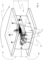
- a system 200 for producing a core for use in casting a gas turbine component is shown in FIGS. 2-4 .
- the system 200 comprises a cavity block 202 having an upper portion 204 and a lower portion 206.
- the upper portion 204 is connected to the lower portion 206 and secured together by a locking mechanism (not shown).
- the system 200 also includes a feed plate 208 through which a core die material is injected into the system.
- the feed plate 208 is attached to the system 200 by a plurality of fasteners 210 and can thus be changed if desired while maintaining the other parts of system 200.
- the feed plate 208 is in communication and aligned with a channel 211, which is in turn in communication with an inlet 224 of a core die insert 220.
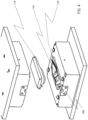
- the upper portion 204 is removed from the lower portion 206, revealing a recessed cavity 212 in the lower portion 206 and upper portion 204 (not shown).
- an adapter insert 214 Positioned within the recessed cavity 212 is an adapter insert 214.
- the adapter insert 214 is sized to fit precisely in the recessed cavity 212 for purposes of supplying the core material and when locked in the cavity block 202, applying the necessary pressure to the core material for it to properly fill the die cavity and solidify.
- the adapter insert 214 can be machined from standard tool steel or a plastic material. Alternatively, the adapter insert 214 can be produced by an additive manufacturing process.
- the adapter insert 214 has a first portion 216 and a second portion 218.
- the adapter insert 214 has profiles in the first portion 216 and second portion 218 corresponding to the shape of a core die insert 220.
- the core die insert 220 Contained within the adapter insert 214 is a core die insert 220, as shown in detail in FIGS. 4 and 5 .
- the core die insert 220 has a hollow internal profile corresponding to an external profile of a core for casting a gas turbine component.
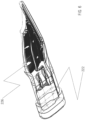
- the core die insert 220 has an external profile 222 as shown in FIG 6 , where the external profile 222 of the core die insert 220 corresponds to the first portion 216 and the second portion 218 of the adapter insert 214.
- the core die insert 220 is fabricated from a sacrificial material, such that it can be easily removed from around a finished solidified core, which is formed in the hollow internal portion of the core die insert 220.
- the core die insert 220 is preferably manufactured from an additive manufacturing process.
- One such material acceptable for use in producing the core die insert is a 3-D printable polymer material (Halcyon), which is a water-soluble material.
- the present disclosure is not limited to this material, but instead, includes any 3-D printable material that is water-soluble and does not interact with the ceramic-based core material.
- the core die insert 220 is manufactured through an additive manufacturing process, it can be formed in multiple pieces, or as a single piece, with a hollow interior in the shape and profile of the core.
- the traditional core die tool is designed to open and with a number of pull planes, or ways in which the core die tool comes apart, so that the core can be removed. Multiple pulls may be necessary depending on the complexity of the core geometry.
- the core does not have to be removed from the core die insert 220 and it is possible to produce a hollow profile which cannot be produced through traditional core tooling.
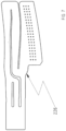
- the core 226 produced as a result of the present disclosure, and depicted in FIGS. 6 and 7 is equally usable in a casting process, as cores produced via traditional tooling.
- the method 300 comprises a step 302 of providing a core injection tooling comprising a cavity block, an adapter insert, and a core die insert.
- a ceramic-based core material is supplied into the core die insert.
- the process of supplying the core material can take on a variety of techniques such as injection, vacuum, pouring, or other material fluid flow technique.
- pressure is applied to the core die insert through the adapter insert and cavity block, and in a step 308, the ceramic-based core material fills and solidifies within the core die insert.
- the core die insert is removed from around the ceramic-based core material by way of placing the resulting core and core die insert in a water-based bath/solution.
- the present disclosure provides a faster way to produce ceramic cores over traditional tooling practices as traditional core tool manufacturing often requires upwards of 20 weeks to produce.
- the core die tooling can be fabricated by an additive manufacturing process and not traditional machining of a block of tool steel, more complex geometries can be formed in the core tool die.
- a sacrificial material such as a water-soluble material, it is easier to remove the tool from around the solidified core.
Landscapes
- Engineering & Computer Science (AREA)
- Mechanical Engineering (AREA)
- Ceramic Engineering (AREA)
- Manufacturing & Machinery (AREA)
- Chemical & Material Sciences (AREA)
- Materials Engineering (AREA)
- Molds, Cores, And Manufacturing Methods Thereof (AREA)
- Turbine Rotor Nozzle Sealing (AREA)
Description
- This present disclosure relates generally to a tool and process for producing a ceramic-based core used in the production of a cooled turbine component. The embodiments of the present disclosure relate to a method of producing a core involving the use of a sacrificial material in the core injection tool.
- A gas turbine engine typically comprises a multi-stage compressor coupled to a multi-stage turbine via an axial shaft. Air enters the gas turbine engine through the compressor where its temperature and pressure are increased as it passes through subsequent stages of the compressor. The compressed air is then directed to one or more combustors where it is mixed with a fuel source to create a combustible mixture. This mixture is ignited in the combustors to create a flow of hot combustion gases. These gases are directed into the turbine causing the turbine to rotate, thereby driving the compressor. The output of the gas turbine engine can be mechanical thrust via exhaust from the turbine or shaft power from the rotation of an axial shaft, where the axial shaft can drive a generator to produce electricity.
- The compressor and turbine each comprise a plurality of rotating blades and stationary vanes having an airfoil extending into the flow of compressed air or flow of hot combustion gases. Each blade or vane has a particular set of design criteria which must be met in order to provide the necessary work to the passing flow through the compressor and the turbine. However, due to the severe nature of the operating environment, especially in the turbine, it is often necessary to cool these blades and vanes.
- Gas turbine components often utilize complex internal cooling passageways in order to maximize the efficiency of cooling fluid passing therethrough. These complex cooling passageways are often created in a casting by utilizing a ceramic core, around which the metal forming the walls of the casting are poured. The ceramic core is subsequently dissolved out of the casting, leaving behind the passageways through which cooling fluid flows. However, manufacturing cores needed to create these complex cooling passageways in a cast component requires expensive and detailed tooling due to core geometry and other cooling enhancements located in the surface of the core.
-
US 2013/0220571 A1 discloses a multi-wall ceramic core for casting an airfoil with one or more internal cooling passages made by preforming at least one fugitive core insert to have a joint-forming surface with a male and/or female joint feature and then forming at least one fugitive core insert in-situ adjacent and integrally connected and fused to the at least one preformed core insert at the joint-forming surface to form an interlocked, fused joint to form a composite core insert that includes features to form internal passage surfaces in the core when the composite core insert is removed. -
US 4 321 010 A discloses a blade or vane structure for a gas turbine engine comprises a hollow aerofoil member and a cooling air entry tube within the hollow aerofoil member, the aerofoil member and the tube comprising a unitary cast structure. To make this structure it is proposed that a lost wax casting process should be utilized, with the internal cavities formed using ceramic cores formed with the aid of temporary, disposable pieces which define the space eventually occupied by the tube. - The present disclosure includes a method and an apparatus for improving the production of cores used in casting complex, advanced gas turbine components. The present disclosure provides multiple improvements in airfoil casting techniques by way of providing improved core production techniques. The present disclosure also provides a way of testing core shapes and cooling features prior to committing to permanent and expensive tooling.
- In an embodiment of the present disclosure, a system for producing a core for use in casting a gas turbine component is disclosed. The system comprises a cavity block having an upper portion and a lower portion and a recessed cavity in each of the upper portion and the lower portion where the upper portion is removably secured to the lower portion. Positioned within the cavity block is an adapter insert, the adapter insert having a first portion and a second portion. A core die insert is located within the adapter insert, where the core die insert is fabricated from a sacrificial material and has a hollow internal profile corresponding to the shape of a core for the gas turbine component.
- The scope of the present invention is defined by independent claim 1, and further embodiments of the invention are specified in dependent claims 2-10.
- The method comprises providing a core injection tooling having a cavity block with an upper portion and a lower portion and a recessed cavity in each of the upper portion and the lower portion, an adapter insert having a first portion and a second portion, the adapter insert sized to fit within the recessed cavities in the cavity block, and a core die insert positioned within the adapter insert. The core die insert, which can be fabricated from an additive manufacturing process, is comprised of a sacrificial material. A ceramic-based material is directed into the core die insert and pressure is applied to the core die insert so that the ceramic-based core material will fill the core die insert and solidify, forming the core. The core die insert is removed from around the solidified core by placing the core die insert and solidified core into a water-based bath.
- In the present invention, a core die insert having an internal cavity, with an internal surface corresponding to an external profile of a core used for casting a gas turbine component, is provided. The core die insert is fabricated from a sacrificial material and has an inlet at one end thereof and is in communication with the internal cavity.
- These and other features of the present disclosure can be best understood from the following description and claims.
- The present disclosure is described in detail below with reference to the attached drawing figures, wherein:
-
FIG. 1 is a perspective view of a core die tool in accordance with the prior art. -
FIG. 2 is a perspective view of a system for producing cores in accordance with an embodiment of the present disclosure. -
FIG. 3 is an alternate perspective view of the system ofFIG. 2 and depicts an upper portion of the cavity block removed, in accordance with an embodiment of the present disclosure. -
FIG. 4 is an alternate perspective view ofFIG. 2 and depicts a portion of an adapter insert removed, in accordance with an embodiment of the present disclosure. -
FIG. 5 is an alternate perspective view ofFIG. 2 and depicts a core die insert in accordance with an embodiment of the present disclosure. -
FIG. 6 is an alternate perspective view ofFIG. 2 and depicts a core produced as a result of the core die insert, in accordance with the present disclosure. -
FIG. 7 is an alternate perspective view of the core ofFIG. 6 produced by the core die insert, in accordance with an embodiment of the present disclosure. -
FIG. 8 is a chart outlining the steps for producing a core in accordance with an embodiment of the present disclosure. - The present disclosure is intended for use in a gas turbine engine, such as a gas turbine used for aircraft engines and/or power generation. As such, the present disclosure is capable of being used in a variety of turbine operating environments, regardless of the manufacturer.
- As those skilled in the art will readily appreciate, a gas turbine engine is circumferentially disposed about an engine centerline, or axial centerline axis. The engine includes a compressor, a combustion section and a turbine with the turbine coupled to the compressor via an engine shaft. As is well known in the art, air compressed in the compressor is mixed with fuel which is burned in the combustion section and expanded in turbine. The air compressed in the compressor and the fuel mixture expanded in the turbine can both be referred to as a "hot gas stream flow." The turbine includes rotors that, in response to the fluid expansion, rotate, thereby driving the compressor. The turbine comprises alternating rows of rotary turbine blades, and static airfoils, often referred to as vanes.
- Due to the temperatures of the hot gas stream flow, which can be well over 2000 deg. F., it is necessary to cool the turbine blades and/or vanes, as operating temperatures are often equal to or greater than the material capability of the turbine components. However, in order to effectively cool critical surfaces of the turbine components, often times a complex internal cooling cavity is required. Producing such a complex internal cooling structure, especially with smaller aerospace components, is extremely difficult to manufacture given the often small size of the components and cooling features. At the same time, it is also desirable to use any cooling air efficiently as cooling air for turbine components is removed from the working process of the engine, thereby lowering overall engine efficiency.
- One way to cool the turbine component is to produce a hollow cavity within the airfoil portion of the blade or vane, where the hollow cavity includes internal passageways for directing the cooling fluid through the component as well as surface features to enhance its cooling effectiveness. Due to the geometric constraints of the components, it is often necessary to cast these features into the gas turbine component, as it is not always possible to machine many of the complex cooling features into the turbine component.
- Referring initially to
FIG. 1 , a core die tool 100 for injecting a ceramic core in accordance with the prior art is shown in perspective view. As can be seen fromFIG. 1 , the core die tool 100 includes atop half 102 andbottom half 104, each having a portion of thecore profile - Referring now to
FIGS. 2-8 , various embodiments of the present disclosure are shown in more detail. Asystem 200 for producing a core for use in casting a gas turbine component is shown inFIGS. 2-4 . Thesystem 200 comprises acavity block 202 having anupper portion 204 and alower portion 206. Theupper portion 204 is connected to thelower portion 206 and secured together by a locking mechanism (not shown). Thesystem 200 also includes afeed plate 208 through which a core die material is injected into the system. Thefeed plate 208 is attached to thesystem 200 by a plurality offasteners 210 and can thus be changed if desired while maintaining the other parts ofsystem 200. Referring now toFIG. 5 , thefeed plate 208 is in communication and aligned with achannel 211, which is in turn in communication with aninlet 224 of acore die insert 220. - Referring now to
FIG. 3 , theupper portion 204 is removed from thelower portion 206, revealing a recessedcavity 212 in thelower portion 206 and upper portion 204 (not shown). Positioned within the recessedcavity 212 is an adapter insert 214. The adapter insert 214 is sized to fit precisely in the recessedcavity 212 for purposes of supplying the core material and when locked in thecavity block 202, applying the necessary pressure to the core material for it to properly fill the die cavity and solidify. The adapter insert 214 can be machined from standard tool steel or a plastic material. Alternatively, the adapter insert 214 can be produced by an additive manufacturing process. - As depicted in
FIGS. 3 and4 , the adapter insert 214 has afirst portion 216 and asecond portion 218. The adapter insert 214 has profiles in thefirst portion 216 andsecond portion 218 corresponding to the shape of acore die insert 220. - Contained within the adapter insert 214 is a
core die insert 220, as shown in detail inFIGS. 4 and5 . The core dieinsert 220 has a hollow internal profile corresponding to an external profile of a core for casting a gas turbine component. The core dieinsert 220 has anexternal profile 222 as shown inFIG 6 , where theexternal profile 222 of the core dieinsert 220 corresponds to thefirst portion 216 and thesecond portion 218 of the adapter insert 214. - The core die
insert 220 is fabricated from a sacrificial material, such that it can be easily removed from around a finished solidified core, which is formed in the hollow internal portion of the core dieinsert 220. The core dieinsert 220 is preferably manufactured from an additive manufacturing process. One such material acceptable for use in producing the core die insert is a 3-D printable polymer material (Halcyon), which is a water-soluble material. The present disclosure is not limited to this material, but instead, includes any 3-D printable material that is water-soluble and does not interact with the ceramic-based core material. - Since the core die
insert 220 is manufactured through an additive manufacturing process, it can be formed in multiple pieces, or as a single piece, with a hollow interior in the shape and profile of the core. As one skilled in the art of investment casting will understand, the traditional core die tool is designed to open and with a number of pull planes, or ways in which the core die tool comes apart, so that the core can be removed. Multiple pulls may be necessary depending on the complexity of the core geometry. By producing acore die insert 220 through an additive manufacturing process, the core does not have to be removed from the core dieinsert 220 and it is possible to produce a hollow profile which cannot be produced through traditional core tooling. Thecore 226 produced as a result of the present disclosure, and depicted inFIGS. 6 and7 , is equally usable in a casting process, as cores produced via traditional tooling. - Referring now to
FIG. 8 , amethod 300 of producing a core for casting a gas turbine component is provided. Themethod 300 comprises astep 302 of providing a core injection tooling comprising a cavity block, an adapter insert, and a core die insert. In astep 304, a ceramic-based core material is supplied into the core die insert. The process of supplying the core material can take on a variety of techniques such as injection, vacuum, pouring, or other material fluid flow technique. Then, in astep 306, pressure is applied to the core die insert through the adapter insert and cavity block, and in astep 308, the ceramic-based core material fills and solidifies within the core die insert. In astep 310, the core die insert is removed from around the ceramic-based core material by way of placing the resulting core and core die insert in a water-based bath/solution. - Numerous advantages are provided by the present disclosure when compared to traditional core die tools and manufacturing processes. For example, the present disclosure provides a faster way to produce ceramic cores over traditional tooling practices as traditional core tool manufacturing often requires upwards of 20 weeks to produce. In addition, since the core die tooling can be fabricated by an additive manufacturing process and not traditional machining of a block of tool steel, more complex geometries can be formed in the core tool die. Furthermore, by fabricating the core die tool from a sacrificial material, such as a water-soluble material, it is easier to remove the tool from around the solidified core.
- Although a preferred embodiment of this disclosure has been disclosed, one of ordinary skill in this art would recognize that certain modifications would come within the scope of this disclosure. For example, while the present disclosure has particular application in the aerospace industry for smaller complex blades and vanes, the core production process outlined herein is also applicable to larger turbine blades and vanes, such as those used in industrial gas turbine components. For that reason, the following claims should be studied to determine the true scope and content of this disclosure. Since many possible embodiments may be made of the disclosure without departing from the scope thereof, it is to be understood that all matter herein set forth or shown in the accompanying drawings is to be interpreted as illustrative and not in a limiting sense.
- From the foregoing, it will be seen that this disclosure is one well adapted to attain all the ends and objects hereinabove set forth together with other advantages which are obvious and which are inherent to the structure.
- It should be noted that the embodiments of the present disclosure is for the explanation of the present disclosure, and not for the limitation of the present invention. The scope of the present invention is defined in the appended claims.
Claims (10)
- A method of producing a core for a gas turbine component casting comprising:providing a core injection tooling comprising a cavity block (202) having an upper portion (204), a lower portion (206), and a recessed cavity (212) in each of the upper portion (204) and the lower portion (206), an adapter insert (214) having a first portion (216) and a second portion (218), the adapter insert (214) sized to fit within the recessed cavities (212) in the cavity block (202), and a core die insert (220) positioned within the adapter insert (214), the core die insert (220) comprised of a sacrificial material;directing a ceramic-based core material into the core die insert (220);applying pressure to the core die insert (220) through the adapter insert (214) and the cavity block (202);solidifying the ceramic-based core material within the core die insert (220); and,removing the core from the core die insert (220);wherein the adapter insert (214) has profiles in the first portion (216) and second portion (218) corresponding to the shape of the core die insert 220, andthe core die insert (220) has a hollow internal profile corresponding to an external profile of the core for casting a gas turbine component, the core die insert (220) has an external profile (222), where the external profile (222) of the core die insert (220) corresponds to the first portion (216) and the second portion (218) of the adapter insert (214).
- The method of claim 1, wherein the core die insert is fabricated from an additive manufacturing process.
- The method of claim 2, wherein the core die insert is fabricated in a single piece.
- The method of claim 2 wherein the core die insert is fabricated in multiple pieces.
- The method of claim 1, wherein the adapter insert (214) is machined from a plastic material.
- The method of claim 1, wherein the step of directing a ceramic-based core material into the core die insert take on a variety of techniques such as injection, vacuum, pouring, or other material fluid flow technique.
- The method of claim 1, wherein the step of removing the core from the core die insert is by way of placing the resulting core and core die insert in a water-based bath/solution.
- The method of claim 2, wherein the material used in the additive manufacturing process is any 3-D printable material that is water-soluble and does not interact with the ceramic-based core material.
- The method of claim 2, wherein the material used in the additive manufacturing process is a 3-D printable polymer material, which is a water-soluble material.
- The method according to claim 1, wherein core die material is injected into the core die insert through a feed plate (208), wherein the feed plate (208) is attached by a plurality of fasteners (210) and can thus be changed if desired while maintaining the other parts, wherein the feed plate (208) is in communication and aligned with a channel (211), which is in turn in communication with an inlet (224) of the core die insert (220).
Applications Claiming Priority (2)
| Application Number | Priority Date | Filing Date | Title |
|---|---|---|---|
| US16/229,425 US11806894B2 (en) | 2018-12-21 | 2018-12-21 | Method and apparatus for improving core manufacturing for gas turbine components |
| PCT/US2019/064154 WO2020131350A1 (en) | 2018-12-21 | 2019-12-03 | Method and apparatus for improving core manufacturing for gas turbine components |
Publications (3)
| Publication Number | Publication Date |
|---|---|
| EP3898026A1 EP3898026A1 (en) | 2021-10-27 |
| EP3898026A4 EP3898026A4 (en) | 2022-08-31 |
| EP3898026B1 true EP3898026B1 (en) | 2024-07-17 |
Family
ID=71099442
Family Applications (1)
| Application Number | Title | Priority Date | Filing Date |
|---|---|---|---|
| EP19898370.2A Active EP3898026B1 (en) | 2018-12-21 | 2019-12-03 | Method of producing a core for casting a gas turbine component |
Country Status (4)
| Country | Link |
|---|---|
| US (2) | US11806894B2 (en) |
| EP (1) | EP3898026B1 (en) |
| PL (1) | PL3898026T3 (en) |
| WO (1) | WO2020131350A1 (en) |
Families Citing this family (4)
| Publication number | Priority date | Publication date | Assignee | Title |
|---|---|---|---|---|
| US11806894B2 (en) * | 2018-12-21 | 2023-11-07 | Chromalloy Gas Turbine Llc | Method and apparatus for improving core manufacturing for gas turbine components |
| CN115135430A (en) * | 2019-11-01 | 2022-09-30 | 西门子能源全球两合公司 | Method for producing flexible tooling for casting ceramic cores |
| US12392259B2 (en) | 2023-10-20 | 2025-08-19 | Chromalloy Gas Turbine Llc | Additively manufactured protective cover for gas turbine components |
| FR3166090A1 (en) * | 2024-09-09 | 2026-03-13 | Safran | METHOD FOR MANUFACTURED AN INJECTION MOLD FOR A MOLDING CORE AND PRECED BY THE MANUFACTURED CERAMIC MOLDING CORE |
Family Cites Families (23)
| Publication number | Priority date | Publication date | Assignee | Title |
|---|---|---|---|---|
| US3871611A (en) * | 1973-05-07 | 1975-03-18 | Taketa Phyllis | Mold with removable and replaceable core and cavity inserts |
| GB2028928B (en) * | 1978-08-17 | 1982-08-25 | Ross Royce Ltd | Aerofoil blade for a gas turbine engine |
| US4737093A (en) * | 1985-06-07 | 1988-04-12 | Kabushiki Kaisha Sanjoseiki Seisakusho | Die locking mechanism for a molding apparatus |
| US6544460B2 (en) * | 1998-11-20 | 2003-04-08 | United Technologies Corporation | Method and fixture for disposing filler material in an article |
| US6782940B2 (en) * | 2000-06-07 | 2004-08-31 | Romain L. Billiet | Method for rapid reproduction of molds and mold components |
| US20020187065A1 (en) * | 2001-06-06 | 2002-12-12 | Amaya Herman Ernesto | Method for the rapid fabrication of mold inserts |
| US20050006047A1 (en) * | 2003-07-10 | 2005-01-13 | General Electric Company | Investment casting method and cores and dies used therein |
| US8245378B2 (en) * | 2007-09-13 | 2012-08-21 | Nike, Inc. | Method and apparatus for manufacturing components used for the manufacture of articles |
| US8196640B1 (en) * | 2010-07-02 | 2012-06-12 | Mikro Systems, Inc. | Self supporting core-in-a-core for casting |
| US8251123B2 (en) * | 2010-12-30 | 2012-08-28 | United Technologies Corporation | Casting core assembly methods |
| US8424585B2 (en) * | 2011-01-21 | 2013-04-23 | James Avery Craftsman, Inc. | Method and apparatus for creating a pattern |
| US8915289B2 (en) | 2011-05-10 | 2014-12-23 | Howmet Corporation | Ceramic core with composite insert for casting airfoils |
| US8393381B2 (en) * | 2011-05-18 | 2013-03-12 | Pcc Airfoils, Inc. | Method of forming a cast metal article |
| US11048829B2 (en) * | 2013-03-15 | 2021-06-29 | Kemeera Llc | 3D printing systems and methods for fabricating injection molds |
| US9987679B2 (en) * | 2013-10-07 | 2018-06-05 | United Technologies Corporation | Rapid tooling insert manufacture |
| US10697305B2 (en) * | 2016-01-08 | 2020-06-30 | General Electric Company | Method for making hybrid ceramic/metal, ceramic/ceramic body by using 3D printing process |
| US20180009128A1 (en) * | 2016-07-08 | 2018-01-11 | Renaissance Services, Inc. | Generation of casting molds by additive manufacturing |
| WO2018055522A1 (en) * | 2016-09-22 | 2018-03-29 | Stratasys Ltd. | Formulation, method and system for solid freeform fabrication |
| US10695826B2 (en) * | 2017-07-17 | 2020-06-30 | Raytheon Technologies Corporation | Apparatus and method for investment casting core manufacture |
| WO2019132912A1 (en) * | 2017-12-28 | 2019-07-04 | Compagnie Generale Des Etablissements Michelin | Mold for manufacturing a spoke for a non-pneumatic tire |
| MX2021000604A (en) * | 2018-07-18 | 2021-07-15 | Poly6 Tech Inc | Articles and methods of manufacture. |
| CN108819049A (en) * | 2018-08-29 | 2018-11-16 | 健大电业制品(昆山)有限公司 | A kind of mold that can quickly change the mold benevolence |
| US11806894B2 (en) * | 2018-12-21 | 2023-11-07 | Chromalloy Gas Turbine Llc | Method and apparatus for improving core manufacturing for gas turbine components |
-
2018
- 2018-12-21 US US16/229,425 patent/US11806894B2/en active Active
-
2019
- 2019-12-03 WO PCT/US2019/064154 patent/WO2020131350A1/en not_active Ceased
- 2019-12-03 EP EP19898370.2A patent/EP3898026B1/en active Active
- 2019-12-03 PL PL19898370.2T patent/PL3898026T3/en unknown
-
2023
- 2023-08-30 US US18/458,820 patent/US12103197B2/en active Active
Also Published As
| Publication number | Publication date |
|---|---|
| PL3898026T3 (en) | 2025-01-20 |
| EP3898026A1 (en) | 2021-10-27 |
| US20200198180A1 (en) | 2020-06-25 |
| US12103197B2 (en) | 2024-10-01 |
| US20230415375A1 (en) | 2023-12-28 |
| EP3898026A4 (en) | 2022-08-31 |
| US11806894B2 (en) | 2023-11-07 |
| WO2020131350A1 (en) | 2020-06-25 |
Similar Documents
| Publication | Publication Date | Title |
|---|---|---|
| US12103197B2 (en) | Method and apparatus for improving core manufacturing for gas turbine components | |
| EP3429778B1 (en) | Method of manufacturing advanced features in a core for casting | |
| EP2841701B1 (en) | Gas turbine engine airfoil impingement cooling | |
| EP2340902B1 (en) | Casting of internal features within a product | |
| JP7086515B2 (en) | 3D manufacturing method and system of turbine parts | |
| EP1495820A1 (en) | Investment casting method | |
| US20150202683A1 (en) | Method of making surface cooling channels on a component using lithographic molding techniques | |
| EP3105422B1 (en) | Blade outer air seal fin cooling assembly and method | |
| EP3296037A1 (en) | Gas turbine component with cooling aperture having shaped inlet and method of forming the same | |
| US11541452B2 (en) | Manufacturing method and tooling for ceramic cores | |
| US11806939B2 (en) | Kinetic disassembly of support structure system for additively manufactured rotating components | |
| CN107309403B (en) | Methods and assemblies for forming parts with jacketed cores | |
| EP3059045A1 (en) | Method of processing unfinished surfaces | |
| US11241735B2 (en) | Methods and apparatuses using cast in core reference features | |
| EP3269929A1 (en) | Gas turbine engine component with cooling passages in wall and method of making the same | |
| EP3433036B1 (en) | Method of manufacturing a hybridized core with protruding cast in cooling features for investment casting | |
| WO2019046036A1 (en) | Method for making a turbine airfoil | |
| US20200208530A1 (en) | Method for making a turbine airfoil | |
| US20190022757A1 (en) | Linkage of composite core features |
Legal Events
| Date | Code | Title | Description |
|---|---|---|---|
| STAA | Information on the status of an ep patent application or granted ep patent |
Free format text: STATUS: THE INTERNATIONAL PUBLICATION HAS BEEN MADE |
|
| PUAI | Public reference made under article 153(3) epc to a published international application that has entered the european phase |
Free format text: ORIGINAL CODE: 0009012 |
|
| STAA | Information on the status of an ep patent application or granted ep patent |
Free format text: STATUS: REQUEST FOR EXAMINATION WAS MADE |
|
| 17P | Request for examination filed |
Effective date: 20210701 |
|
| AK | Designated contracting states |
Kind code of ref document: A1 Designated state(s): AL AT BE BG CH CY CZ DE DK EE ES FI FR GB GR HR HU IE IS IT LI LT LU LV MC MK MT NL NO PL PT RO RS SE SI SK SM TR |
|
| DAV | Request for validation of the european patent (deleted) | ||
| DAX | Request for extension of the european patent (deleted) | ||
| A4 | Supplementary search report drawn up and despatched |
Effective date: 20220802 |
|
| RIC1 | Information provided on ipc code assigned before grant |
Ipc: F01D 5/18 20060101ALI20220727BHEP Ipc: B33Y 80/00 20150101ALI20220727BHEP Ipc: B28B 7/34 20060101ALI20220727BHEP Ipc: B28B 1/24 20060101ALI20220727BHEP Ipc: B22C 7/06 20060101ALI20220727BHEP Ipc: B22C 9/10 20060101AFI20220727BHEP |
|
| RIN1 | Information on inventor provided before grant (corrected) |
Inventor name: MOLKENTIN, THOMAS Inventor name: ORAS, ZACHARY Inventor name: DODDS, GERALD CLEMENT |
|
| STAA | Information on the status of an ep patent application or granted ep patent |
Free format text: STATUS: EXAMINATION IS IN PROGRESS |
|
| 17Q | First examination report despatched |
Effective date: 20230911 |
|
| REG | Reference to a national code |
Ref legal event code: R079 Ref country code: DE Ref legal event code: R079 Ref document number: 602019055534 Country of ref document: DE Free format text: PREVIOUS MAIN CLASS: B22C0009100000 Ipc: B28B0001240000 |
|
| RIC1 | Information provided on ipc code assigned before grant |
Ipc: B33Y 80/00 20150101ALI20240103BHEP Ipc: B28B 7/34 20060101ALI20240103BHEP Ipc: B28B 1/24 20060101AFI20240103BHEP Ipc: F01D 5/18 20060101ALN20240103BHEP Ipc: B22C 9/10 20060101ALI20240103BHEP Ipc: B22C 7/06 20060101ALI20240103BHEP |
|
| GRAP | Despatch of communication of intention to grant a patent |
Free format text: ORIGINAL CODE: EPIDOSNIGR1 |
|
| STAA | Information on the status of an ep patent application or granted ep patent |
Free format text: STATUS: GRANT OF PATENT IS INTENDED |
|
| INTG | Intention to grant announced |
Effective date: 20240214 |
|
| GRAS | Grant fee paid |
Free format text: ORIGINAL CODE: EPIDOSNIGR3 |
|
| GRAA | (expected) grant |
Free format text: ORIGINAL CODE: 0009210 |
|
| STAA | Information on the status of an ep patent application or granted ep patent |
Free format text: STATUS: THE PATENT HAS BEEN GRANTED |
|
| AK | Designated contracting states |
Kind code of ref document: B1 Designated state(s): AL AT BE BG CH CY CZ DE DK EE ES FI FR GB GR HR HU IE IS IT LI LT LU LV MC MK MT NL NO PL PT RO RS SE SI SK SM TR |
|
| REG | Reference to a national code |
Ref country code: CH Ref legal event code: EP |
|
| REG | Reference to a national code |
Ref country code: DE Ref legal event code: R096 Ref document number: 602019055534 Country of ref document: DE |
|
| REG | Reference to a national code |
Ref country code: IE Ref legal event code: FG4D |
|
| REG | Reference to a national code |
Ref country code: LT Ref legal event code: MG9D |
|
| REG | Reference to a national code |
Ref country code: NL Ref legal event code: MP Effective date: 20240717 |
|
| PG25 | Lapsed in a contracting state [announced via postgrant information from national office to epo] |
Ref country code: PT Free format text: LAPSE BECAUSE OF FAILURE TO SUBMIT A TRANSLATION OF THE DESCRIPTION OR TO PAY THE FEE WITHIN THE PRESCRIBED TIME-LIMIT Effective date: 20241118 |
|
| REG | Reference to a national code |
Ref country code: AT Ref legal event code: MK05 Ref document number: 1703729 Country of ref document: AT Kind code of ref document: T Effective date: 20240717 |
|
| PG25 | Lapsed in a contracting state [announced via postgrant information from national office to epo] |
Ref country code: NL Free format text: LAPSE BECAUSE OF FAILURE TO SUBMIT A TRANSLATION OF THE DESCRIPTION OR TO PAY THE FEE WITHIN THE PRESCRIBED TIME-LIMIT Effective date: 20240717 |
|
| PG25 | Lapsed in a contracting state [announced via postgrant information from national office to epo] |
Ref country code: PT Free format text: LAPSE BECAUSE OF FAILURE TO SUBMIT A TRANSLATION OF THE DESCRIPTION OR TO PAY THE FEE WITHIN THE PRESCRIBED TIME-LIMIT Effective date: 20241118 Ref country code: NL Free format text: LAPSE BECAUSE OF FAILURE TO SUBMIT A TRANSLATION OF THE DESCRIPTION OR TO PAY THE FEE WITHIN THE PRESCRIBED TIME-LIMIT Effective date: 20240717 |
|
| PG25 | Lapsed in a contracting state [announced via postgrant information from national office to epo] |
Ref country code: NO Free format text: LAPSE BECAUSE OF FAILURE TO SUBMIT A TRANSLATION OF THE DESCRIPTION OR TO PAY THE FEE WITHIN THE PRESCRIBED TIME-LIMIT Effective date: 20241017 |
|
| PG25 | Lapsed in a contracting state [announced via postgrant information from national office to epo] |
Ref country code: GR Free format text: LAPSE BECAUSE OF FAILURE TO SUBMIT A TRANSLATION OF THE DESCRIPTION OR TO PAY THE FEE WITHIN THE PRESCRIBED TIME-LIMIT Effective date: 20241018 Ref country code: FI Free format text: LAPSE BECAUSE OF FAILURE TO SUBMIT A TRANSLATION OF THE DESCRIPTION OR TO PAY THE FEE WITHIN THE PRESCRIBED TIME-LIMIT Effective date: 20240717 |
|
| PG25 | Lapsed in a contracting state [announced via postgrant information from national office to epo] |
Ref country code: BG Free format text: LAPSE BECAUSE OF FAILURE TO SUBMIT A TRANSLATION OF THE DESCRIPTION OR TO PAY THE FEE WITHIN THE PRESCRIBED TIME-LIMIT Effective date: 20240717 |
|
| PG25 | Lapsed in a contracting state [announced via postgrant information from national office to epo] |
Ref country code: LV Free format text: LAPSE BECAUSE OF FAILURE TO SUBMIT A TRANSLATION OF THE DESCRIPTION OR TO PAY THE FEE WITHIN THE PRESCRIBED TIME-LIMIT Effective date: 20240717 |
|
| PG25 | Lapsed in a contracting state [announced via postgrant information from national office to epo] |
Ref country code: IS Free format text: LAPSE BECAUSE OF FAILURE TO SUBMIT A TRANSLATION OF THE DESCRIPTION OR TO PAY THE FEE WITHIN THE PRESCRIBED TIME-LIMIT Effective date: 20241117 Ref country code: AT Free format text: LAPSE BECAUSE OF FAILURE TO SUBMIT A TRANSLATION OF THE DESCRIPTION OR TO PAY THE FEE WITHIN THE PRESCRIBED TIME-LIMIT Effective date: 20240717 |
|
| PG25 | Lapsed in a contracting state [announced via postgrant information from national office to epo] |
Ref country code: HR Free format text: LAPSE BECAUSE OF FAILURE TO SUBMIT A TRANSLATION OF THE DESCRIPTION OR TO PAY THE FEE WITHIN THE PRESCRIBED TIME-LIMIT Effective date: 20240717 |
|
| PG25 | Lapsed in a contracting state [announced via postgrant information from national office to epo] |
Ref country code: RS Free format text: LAPSE BECAUSE OF FAILURE TO SUBMIT A TRANSLATION OF THE DESCRIPTION OR TO PAY THE FEE WITHIN THE PRESCRIBED TIME-LIMIT Effective date: 20241017 Ref country code: ES Free format text: LAPSE BECAUSE OF FAILURE TO SUBMIT A TRANSLATION OF THE DESCRIPTION OR TO PAY THE FEE WITHIN THE PRESCRIBED TIME-LIMIT Effective date: 20240717 |
|
| PG25 | Lapsed in a contracting state [announced via postgrant information from national office to epo] |
Ref country code: RS Free format text: LAPSE BECAUSE OF FAILURE TO SUBMIT A TRANSLATION OF THE DESCRIPTION OR TO PAY THE FEE WITHIN THE PRESCRIBED TIME-LIMIT Effective date: 20241017 Ref country code: NO Free format text: LAPSE BECAUSE OF FAILURE TO SUBMIT A TRANSLATION OF THE DESCRIPTION OR TO PAY THE FEE WITHIN THE PRESCRIBED TIME-LIMIT Effective date: 20241017 Ref country code: LV Free format text: LAPSE BECAUSE OF FAILURE TO SUBMIT A TRANSLATION OF THE DESCRIPTION OR TO PAY THE FEE WITHIN THE PRESCRIBED TIME-LIMIT Effective date: 20240717 Ref country code: IS Free format text: LAPSE BECAUSE OF FAILURE TO SUBMIT A TRANSLATION OF THE DESCRIPTION OR TO PAY THE FEE WITHIN THE PRESCRIBED TIME-LIMIT Effective date: 20241117 Ref country code: HR Free format text: LAPSE BECAUSE OF FAILURE TO SUBMIT A TRANSLATION OF THE DESCRIPTION OR TO PAY THE FEE WITHIN THE PRESCRIBED TIME-LIMIT Effective date: 20240717 Ref country code: GR Free format text: LAPSE BECAUSE OF FAILURE TO SUBMIT A TRANSLATION OF THE DESCRIPTION OR TO PAY THE FEE WITHIN THE PRESCRIBED TIME-LIMIT Effective date: 20241018 Ref country code: FI Free format text: LAPSE BECAUSE OF FAILURE TO SUBMIT A TRANSLATION OF THE DESCRIPTION OR TO PAY THE FEE WITHIN THE PRESCRIBED TIME-LIMIT Effective date: 20240717 Ref country code: ES Free format text: LAPSE BECAUSE OF FAILURE TO SUBMIT A TRANSLATION OF THE DESCRIPTION OR TO PAY THE FEE WITHIN THE PRESCRIBED TIME-LIMIT Effective date: 20240717 Ref country code: BG Free format text: LAPSE BECAUSE OF FAILURE TO SUBMIT A TRANSLATION OF THE DESCRIPTION OR TO PAY THE FEE WITHIN THE PRESCRIBED TIME-LIMIT Effective date: 20240717 Ref country code: AT Free format text: LAPSE BECAUSE OF FAILURE TO SUBMIT A TRANSLATION OF THE DESCRIPTION OR TO PAY THE FEE WITHIN THE PRESCRIBED TIME-LIMIT Effective date: 20240717 |
|
| PG25 | Lapsed in a contracting state [announced via postgrant information from national office to epo] |
Ref country code: DK Free format text: LAPSE BECAUSE OF FAILURE TO SUBMIT A TRANSLATION OF THE DESCRIPTION OR TO PAY THE FEE WITHIN THE PRESCRIBED TIME-LIMIT Effective date: 20240717 Ref country code: RO Free format text: LAPSE BECAUSE OF FAILURE TO SUBMIT A TRANSLATION OF THE DESCRIPTION OR TO PAY THE FEE WITHIN THE PRESCRIBED TIME-LIMIT Effective date: 20240717 Ref country code: SM Free format text: LAPSE BECAUSE OF FAILURE TO SUBMIT A TRANSLATION OF THE DESCRIPTION OR TO PAY THE FEE WITHIN THE PRESCRIBED TIME-LIMIT Effective date: 20240717 |
|
| REG | Reference to a national code |
Ref country code: DE Ref legal event code: R097 Ref document number: 602019055534 Country of ref document: DE |
|
| PG25 | Lapsed in a contracting state [announced via postgrant information from national office to epo] |
Ref country code: EE Free format text: LAPSE BECAUSE OF FAILURE TO SUBMIT A TRANSLATION OF THE DESCRIPTION OR TO PAY THE FEE WITHIN THE PRESCRIBED TIME-LIMIT Effective date: 20240717 |
|
| PG25 | Lapsed in a contracting state [announced via postgrant information from national office to epo] |
Ref country code: CZ Free format text: LAPSE BECAUSE OF FAILURE TO SUBMIT A TRANSLATION OF THE DESCRIPTION OR TO PAY THE FEE WITHIN THE PRESCRIBED TIME-LIMIT Effective date: 20240717 |
|
| PG25 | Lapsed in a contracting state [announced via postgrant information from national office to epo] |
Ref country code: SK Free format text: LAPSE BECAUSE OF FAILURE TO SUBMIT A TRANSLATION OF THE DESCRIPTION OR TO PAY THE FEE WITHIN THE PRESCRIBED TIME-LIMIT Effective date: 20240717 |
|
| PLBE | No opposition filed within time limit |
Free format text: ORIGINAL CODE: 0009261 |
|
| STAA | Information on the status of an ep patent application or granted ep patent |
Free format text: STATUS: NO OPPOSITION FILED WITHIN TIME LIMIT |
|
| 26N | No opposition filed |
Effective date: 20250422 |
|
| PG25 | Lapsed in a contracting state [announced via postgrant information from national office to epo] |
Ref country code: MC Free format text: LAPSE BECAUSE OF FAILURE TO SUBMIT A TRANSLATION OF THE DESCRIPTION OR TO PAY THE FEE WITHIN THE PRESCRIBED TIME-LIMIT Effective date: 20240717 |
|
| REG | Reference to a national code |
Ref country code: CH Ref legal event code: PL |
|
| PG25 | Lapsed in a contracting state [announced via postgrant information from national office to epo] |
Ref country code: LU Free format text: LAPSE BECAUSE OF NON-PAYMENT OF DUE FEES Effective date: 20241203 |
|
| PG25 | Lapsed in a contracting state [announced via postgrant information from national office to epo] |
Ref country code: SE Free format text: LAPSE BECAUSE OF FAILURE TO SUBMIT A TRANSLATION OF THE DESCRIPTION OR TO PAY THE FEE WITHIN THE PRESCRIBED TIME-LIMIT Effective date: 20240717 |
|
| REG | Reference to a national code |
Ref country code: BE Ref legal event code: MM Effective date: 20241231 |
|
| PGFP | Annual fee paid to national office [announced via postgrant information from national office to epo] |
Ref country code: PL Payment date: 20250912 Year of fee payment: 7 |
|
| PG25 | Lapsed in a contracting state [announced via postgrant information from national office to epo] |
Ref country code: BE Free format text: LAPSE BECAUSE OF NON-PAYMENT OF DUE FEES Effective date: 20241231 |
|
| PG25 | Lapsed in a contracting state [announced via postgrant information from national office to epo] |
Ref country code: FR Free format text: LAPSE BECAUSE OF NON-PAYMENT OF DUE FEES Effective date: 20241231 |
|
| PG25 | Lapsed in a contracting state [announced via postgrant information from national office to epo] |
Ref country code: CH Free format text: LAPSE BECAUSE OF NON-PAYMENT OF DUE FEES Effective date: 20241231 |
|
| PG25 | Lapsed in a contracting state [announced via postgrant information from national office to epo] |
Ref country code: IE Free format text: LAPSE BECAUSE OF NON-PAYMENT OF DUE FEES Effective date: 20241203 |
|
| PGFP | Annual fee paid to national office [announced via postgrant information from national office to epo] |
Ref country code: DE Payment date: 20250930 Year of fee payment: 7 |
|
| PGFP | Annual fee paid to national office [announced via postgrant information from national office to epo] |
Ref country code: GB Payment date: 20251001 Year of fee payment: 7 |
|
| PG25 | Lapsed in a contracting state [announced via postgrant information from national office to epo] |
Ref country code: IT Free format text: LAPSE BECAUSE OF FAILURE TO SUBMIT A TRANSLATION OF THE DESCRIPTION OR TO PAY THE FEE WITHIN THE PRESCRIBED TIME-LIMIT Effective date: 20240717 |
|
| PG25 | Lapsed in a contracting state [announced via postgrant information from national office to epo] |
Ref country code: CY Free format text: LAPSE BECAUSE OF FAILURE TO SUBMIT A TRANSLATION OF THE DESCRIPTION OR TO PAY THE FEE WITHIN THE PRESCRIBED TIME-LIMIT; INVALID AB INITIO Effective date: 20191203 |