EP3897509B1 - Enteral nutrition container cap and methods of making and using the cap - Google Patents
Enteral nutrition container cap and methods of making and using the cap Download PDFInfo
- Publication number
- EP3897509B1 EP3897509B1 EP19835300.5A EP19835300A EP3897509B1 EP 3897509 B1 EP3897509 B1 EP 3897509B1 EP 19835300 A EP19835300 A EP 19835300A EP 3897509 B1 EP3897509 B1 EP 3897509B1
- Authority
- EP
- European Patent Office
- Prior art keywords
- cap
- spout
- overcap
- enteral
- upper portion
- Prior art date
- Legal status (The legal status is an assumption and is not a legal conclusion. Google has not performed a legal analysis and makes no representation as to the accuracy of the status listed.)
- Active
Links
Images


Classifications
-
- A—HUMAN NECESSITIES
- A61—MEDICAL OR VETERINARY SCIENCE; HYGIENE
- A61J—CONTAINERS SPECIALLY ADAPTED FOR MEDICAL OR PHARMACEUTICAL PURPOSES; DEVICES OR METHODS SPECIALLY ADAPTED FOR BRINGING PHARMACEUTICAL PRODUCTS INTO PARTICULAR PHYSICAL OR ADMINISTERING FORMS; DEVICES FOR ADMINISTERING FOOD OR MEDICINES ORALLY; BABY COMFORTERS; DEVICES FOR RECEIVING SPITTLE
- A61J1/00—Containers specially adapted for medical or pharmaceutical purposes
- A61J1/14—Details; Accessories therefor
- A61J1/1475—Inlet or outlet ports
- A61J1/1481—Inlet or outlet ports with connection retaining means, e.g. thread or snap-fit
-
- A—HUMAN NECESSITIES
- A61—MEDICAL OR VETERINARY SCIENCE; HYGIENE
- A61J—CONTAINERS SPECIALLY ADAPTED FOR MEDICAL OR PHARMACEUTICAL PURPOSES; DEVICES OR METHODS SPECIALLY ADAPTED FOR BRINGING PHARMACEUTICAL PRODUCTS INTO PARTICULAR PHYSICAL OR ADMINISTERING FORMS; DEVICES FOR ADMINISTERING FOOD OR MEDICINES ORALLY; BABY COMFORTERS; DEVICES FOR RECEIVING SPITTLE
- A61J1/00—Containers specially adapted for medical or pharmaceutical purposes
- A61J1/14—Details; Accessories therefor
- A61J1/1412—Containers with closing means, e.g. caps
- A61J1/1418—Threaded type
-
- A—HUMAN NECESSITIES
- A61—MEDICAL OR VETERINARY SCIENCE; HYGIENE
- A61J—CONTAINERS SPECIALLY ADAPTED FOR MEDICAL OR PHARMACEUTICAL PURPOSES; DEVICES OR METHODS SPECIALLY ADAPTED FOR BRINGING PHARMACEUTICAL PRODUCTS INTO PARTICULAR PHYSICAL OR ADMINISTERING FORMS; DEVICES FOR ADMINISTERING FOOD OR MEDICINES ORALLY; BABY COMFORTERS; DEVICES FOR RECEIVING SPITTLE
- A61J1/00—Containers specially adapted for medical or pharmaceutical purposes
- A61J1/14—Details; Accessories therefor
- A61J1/18—Arrangements for indicating condition of container contents, e.g. sterile condition
-
- A—HUMAN NECESSITIES
- A61—MEDICAL OR VETERINARY SCIENCE; HYGIENE
- A61J—CONTAINERS SPECIALLY ADAPTED FOR MEDICAL OR PHARMACEUTICAL PURPOSES; DEVICES OR METHODS SPECIALLY ADAPTED FOR BRINGING PHARMACEUTICAL PRODUCTS INTO PARTICULAR PHYSICAL OR ADMINISTERING FORMS; DEVICES FOR ADMINISTERING FOOD OR MEDICINES ORALLY; BABY COMFORTERS; DEVICES FOR RECEIVING SPITTLE
- A61J1/00—Containers specially adapted for medical or pharmaceutical purposes
- A61J1/14—Details; Accessories therefor
- A61J1/20—Arrangements for transferring or mixing fluids, e.g. from vial to syringe
- A61J1/2003—Accessories used in combination with means for transfer or mixing of fluids, e.g. for activating fluid flow, separating fluids, filtering fluid or venting
- A61J1/2006—Piercing means
- A61J1/201—Piercing means having one piercing end
-
- A—HUMAN NECESSITIES
- A61—MEDICAL OR VETERINARY SCIENCE; HYGIENE
- A61J—CONTAINERS SPECIALLY ADAPTED FOR MEDICAL OR PHARMACEUTICAL PURPOSES; DEVICES OR METHODS SPECIALLY ADAPTED FOR BRINGING PHARMACEUTICAL PRODUCTS INTO PARTICULAR PHYSICAL OR ADMINISTERING FORMS; DEVICES FOR ADMINISTERING FOOD OR MEDICINES ORALLY; BABY COMFORTERS; DEVICES FOR RECEIVING SPITTLE
- A61J15/00—Feeding-tubes for therapeutic purposes
- A61J15/0026—Parts, details or accessories for feeding-tubes
-
- A—HUMAN NECESSITIES
- A61—MEDICAL OR VETERINARY SCIENCE; HYGIENE
- A61J—CONTAINERS SPECIALLY ADAPTED FOR MEDICAL OR PHARMACEUTICAL PURPOSES; DEVICES OR METHODS SPECIALLY ADAPTED FOR BRINGING PHARMACEUTICAL PRODUCTS INTO PARTICULAR PHYSICAL OR ADMINISTERING FORMS; DEVICES FOR ADMINISTERING FOOD OR MEDICINES ORALLY; BABY COMFORTERS; DEVICES FOR RECEIVING SPITTLE
- A61J9/00—Feeding-bottles in general
-
- A—HUMAN NECESSITIES
- A61—MEDICAL OR VETERINARY SCIENCE; HYGIENE
- A61M—DEVICES FOR INTRODUCING MEDIA INTO, OR ONTO, THE BODY; DEVICES FOR TRANSDUCING BODY MEDIA OR FOR TAKING MEDIA FROM THE BODY; DEVICES FOR PRODUCING OR ENDING SLEEP OR STUPOR
- A61M5/00—Devices for bringing media into the body in a subcutaneous, intra-vascular or intramuscular way; Accessories therefor, e.g. filling or cleaning devices, arm-rests
- A61M5/14—Infusion devices, e.g. infusing by gravity; Blood infusion; Accessories therefor
- A61M5/162—Needle sets, i.e. connections by puncture between reservoir and tube ; Connections between reservoir and tube
-
- B—PERFORMING OPERATIONS; TRANSPORTING
- B65—CONVEYING; PACKING; STORING; HANDLING THIN OR FILAMENTARY MATERIAL
- B65D—CONTAINERS FOR STORAGE OR TRANSPORT OF ARTICLES OR MATERIALS, e.g. BAGS, BARRELS, BOTTLES, BOXES, CANS, CARTONS, CRATES, DRUMS, JARS, TANKS, HOPPERS, FORWARDING CONTAINERS; ACCESSORIES, CLOSURES, OR FITTINGS THEREFOR; PACKAGING ELEMENTS; PACKAGES
- B65D75/00—Packages comprising articles or materials partially or wholly enclosed in strips, sheets, blanks, tubes or webs of flexible sheet material, e.g. in folded wrappers
- B65D75/52—Details
- B65D75/58—Opening or contents-removing devices added or incorporated during package manufacture
- B65D75/5861—Spouts
- B65D75/5872—Non-integral spouts
- B65D75/5883—Non-integral spouts connected to the package at the sealed junction of two package walls
Definitions
- connection quality and spillage when connecting a container to a feeding device are connection quality and spillage when connecting a container to a feeding device.
- Some nutritional compositions may be dual use, so another common concern is to provide a container that may be used for consumption both orally and as enteral nutrition.
- a common method to deliver nutritional compositions to a patient is to pour the nutritional composition from a container into an open syringe attached to a feeding tube. Such methods may be difficult for children or patients with fine motor skills challenges. As a result, the nutritional composition may spill out of the open syringe attached to a feeding tube.
- WO 2004/045705 discloses a connector device suitable for connecting an enteral administration set to a laminated paper packaging system comprising enterally administrable medical or nutritional food.
- WO 2018/067629 discloses a syringe having a barrel and a non-luer tip that is not connectable to an intravenous device.
- the syringe has an enteral collar having a distal end and proximal end, the proximal end having a syringe engagement feature.
- the enteral collar is sized to permit an ENFit connection to an enteral device and prevent connection to a device having a luer connector.
- a package closure system is provided according to claim 1.
- a method for providing a nutritional composition is provided according to claim 15.
- the preferred embodiments relate to a cap or connector methods and devices for connecting a container containing nutritional compositions to an enteral feeding device, where the cap or connector may also be used for oral ingestion of the nutritional compositions.
- FIG. 1 generally illustrates an embodiment of a cap 10.
- the cap 10 can comprise: an upper portion 12 for connecting to an external receiving member and/or an overcap 70 as shown in FIGS. 10 and 11 ; and a lower portion 11 for connecting to a container 131.
- the external receiving member may be a male ENFit ® connector.
- a female ENFit ® connector positioned on the upper portion 12 of the cap 10 may be connected to the male ENFit ® connector of the external receiving member.
- the external connector may be a female ENFit ® connector
- the upper portion 12 of the cap 10 may be configured as a male ENFit ® connector, for connecting to the female ENFit ® connector of the external receiving member.
- the cap 10 may be provided with outer ridges 14 along an outer circumference of the lower portion 11. The outer ridges 14 may be configured to assist a user when removing, manipulating and/or attaching the cap to other systems or devices.
- the cap 10 may screw onto other devices containing nutritional product (e.g., a flexible pouch, a SmartFlex Bottle ® , a water bottle, a Resource Junior ® bottle, an Infrasource ® bottle, Tetra ® Bottle, other NHSc bottles, and/or other bottles known in the art).
- a flexible pouch e.g., a SmartFlex Bottle ® , a water bottle, a Resource Junior ® bottle, an Infrasource ® bottle, Tetra ® Bottle, other NHSc bottles, and/or other bottles known in the art.
- other features of the cap 10 may be provided, for example, larger dimensions, extensions (i.e., wings for grabbing by a user) and/or textured surfaces may be provided as part of the cap 10.
- the cap 10 thereby provides direct connection of a container 131 for a nutitional composition with an enteral line feeding tube, without the use of a giving set, administration set or other adaptor.
- the outer ridges 14 may be configured perpendicularly to a plane defined by a smallest cross sectional plane of the cap 10, as shown in FIG. 1 . Additionally or alternatively, the outer ridges 14 may be crosshatched, textured, and/or comprised of the same or different material as the rest of the cap 10. For example, the outer ridges 14 may be rubber.
- the cap 10 may be provided with upper connecting threads 13 extending from the upper portion 12.
- the upper connecting threads 13 may be configured to attach to an ENFit ® connector.
- the cap 10 may not be provided with connecting threads 13, and may instead be provided with a clip, snap, plug, fitting and/or other connector for connecting the cap 10 to an external receiving member. More or fewer and/or different connecting threads may be manufactured than the connecting threads 13 shown in FIG. 1 .
- the cap 10 may only partially comply with ENFit ® connector standards.
- the cap 10 may be provided with a larger bore size than that provided in the ENFit ® connector standards to reduce any flow restriction through the cap 10.
- the cap 10, as well as connecting components such as the overcap 70, shown in FIGS. 10 and 11 may be manufactured from materials including, but not limited to plastics, sustainable plastics, glass, metal, paper, fiber, carton, edible materials (e.g., fiber, sugar, chews, etc.) and combinations thereof.
- the cap 10 may be configured to indicate a temperature, a pH, and/or other parameter of a nutritional composition 132, shown in FIG. 10 ; for example, by manufacturing the cap 10 from a material responsive to the temperature and/or the pH.
- the color of the cap 10 may correlate to a use for the nutritional composition 132; for example, a cap color may correlate to an embodiment of the nutritional composition 132 where the nutritional composition 132 is optimized to fulfill a specific nutritional requirement.
- the cap 10 may be manufactured from a flexible material, enabling the cap 10 to be used as a straw.
- the cap 10 may be manufactured from a transparent material or comprise a transparent section to enable the observation of the nutritional composition 132 flowing through the cap 10.
- FIG. 2 generally illustrates a view of the lower portion 11 of the cap 10.
- the upper connecting threads 13 are shown, as well as the outer ridges 14.
- FIG. 2 shows lower receiving threads 21, which may be positioned within a lower cavity 22 of the cap 10.
- the lower receiving threads 21 may be configured to attach to the container 131, thereby engaging the container 131 and allowing the nutritional composition 132 to flow from the container 131, into the lower cavity 22, and through other portions of the cap 10.
- FIG. 3 generally illustrates an isometric view of the cap 10, which may include: the upper portion 12 with the upper connecting threads 13; and the lower portion 11 with the outer ridges 14.
- FIG. 4 generally illustrates a side view of the cap 10, which may include: the upper portion 12 with the upper connecting threads 13; and the lower portion 11 with the outer ridges 14.
- a centerline 41 is shown for reference, which passes through a midline of the generally cylindrical structure of the cap 10.
- An upper portion base 42 may provide an interface between the upper portion 12 and the lower portion 11.
- a lower portion base 43 is shown, which can be positioned on the distal end of the lower portion 11 from the upper portion 12.
- a portion of the cap 10 between the upper portion base 42 and the ridges 14 may be elongated to be used as a straw and/or to be more easily manipulated by a user. Such an embodiment may provide better ergonomics and/or better visibility to material flowing through the cap 10 if the cap 10 is manufactured from a transparent material.
- the upper portion 12 of the cap 10 may be retractable, i.e. the upper portion 12 with second connection element 13 may reversible retract, partially or fully, into the cavity 22 of lower portion 11.
- FIG. 5 generally illustrates a cutaway view of the upper portion 12 and the lower portion 11 of the cap 10.
- the cap 10 includes an upper cavity 51 that connects to the lower cavity 22, also shown in FIG. 2 .
- the lower receiving threads 21 may extend around an inner circumference of the lower portion 11.
- the lower receiving threads 21 may extend through the lower portion base 43 to aid the lower portion 11 (e.g., the lower receiving threads 21) in connecting to another connection member.
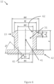
- FIG. 6 generally illustrates a dimensioned cutaway view of the upper portion 12 of the cap 10, wherein the upper portion 12 of the cap 10 is adapted for ENFit ® compatibility.
- the upper cavity 51 is shown, which may extend through the upper portion 12 along the centerline 41.
- the upper cavity 51 may be defined by an upper portion inner wall 62, and have an upper portion inner wall diameter ⁇ D and an upper portion length above base E.
- a transmission opening 61 may be provided at a distal end of the upper portion 12 from the upper connecting threads 13.
- the transmission opening 61 may be defined by a transmission opening diameter ⁇ U.
- the transmission opening diameter ⁇ U may be smaller than an upper portion base inner diameter ⁇ G.
- the transmission opening diameter ⁇ U may create a flow restriction for the nutritional composition 132 flowing through the upper portion 12.
- a transmission opening chamfer angle T3 may be configured to throttle the flow restriction to adjust flow characteristics, for example flow speed and/or turbulence.
- the upper portion base inner diameter ⁇ G and the transmission opening diameter ⁇ U may be equal or about equal, therefore eliminating the flow restriction and resulting in the transmission opening chamfer angle T3 being 90° or about 90°.
- the upper portion 12 may comprise an upper portion diameter ⁇ J, which may correspond to a diameter of the outer walls of the upper portion 12.
- the upper connecting threads 13 extend beyond the upper portion diameter ⁇ J.
- the upper connecting threads 13 may have an upper connecting threads diameter ⁇ H around the centerline 41, where the upper portion diameter ⁇ J is smaller than the upper connecting threads diameter ⁇ H.
- the upper connecting threads 13 may have a thread crest width M and a thread pitch width N, where the thread pitch width N is preferably a widest point of the upper connecting threads 13.
- the upper connecting threads 13 may contact the upper portion 12 at the widest point of the upper connecting threads 13.
- the upper connecting threads 13 may then taper to the most distal portion of the upper connecting threads 13, which may have the thread crest width M.
- the thread crest width M may be zero or about zero.
- the pitch thread width N and the thread crest width M may be equal or about equal, resulting in the upper connecting threads 13 being un-tapered (i.e., straight-cut).
- the relative proportions given in FIG. 6 may be varied to meet different user needs.
- the upper portion length above base E may be elongated to allow the cap 10 to be used as a straw and/or more easily manipulated by a user.
- the upper portion diameter ⁇ J may be much larger to allow a user to apply more torque to the cap 10 when screwing the cap 10 into a device and/or a component.
- the upper portion inner wall diameter ⁇ D may be optimized for a desired flow rate though the cap 10.
- the dimensions including at least the thread crest width M, the thread pitch width N and the upper connecting threads diameter ⁇ H may be adapted for connecting to a specific device and/or a specific component.
- the cap 10 may include a strip of foil and/or a seal across the upper portion inner wall diameter ⁇ D.
- the strip of foil and/or the seal can signal to a user that the cap 10, the container 131, and/or other structure has been tampered with.
- the strip of foil and/or the seal may also provide added protection against leaks when shipping and/or handling the container 131.
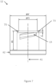
- FIG. 7 generally illustrates a side view of an embodiment of the upper portion 12 of the cap 10.
- the upper portion 12 is shown with upper connecting threads 13.
- the upper portion 12 may generally be defined by a base width ⁇ W, a top width ⁇ F3 and a length above base R3.
- the upper portion 12 may include chamfers 73 at an opposite end from the base portion 42 along the centerline 41, and the chamfers 73 may be defined by a chamfer height C.
- FIG. 8 generally illustrates an isometric view of the upper portion 12 of the cap 10, adapted for ENFit ® compatibility.
- the upper portion 12 may include upper connecting threads 13, which may extend radially outward from the center of the generally cylindrical structure of the upper portion 12.
- the upper connection threads 13 may be positioned in a plane offset from a plane defined by the upper portion base 42. As the upper connecting threads 13 extend upward, the threads may terminate at an upper connecting thread terminus edge width X3.
- the upper connecting thread terminus edge width X3 may be provided to prevent misconnection of the cap 10.
- a configuration of the upper portion 12 may comprise an embodiment of the upper connecting thread terminus edge width X3 where the upper connecting thread terminus edge width X3 is maximized because the contact area provided by a longer embodiment of the upper connecting thread terminus edge width X3 may provide a larger sealing area.
- FIG. 9 generally illustrates a through-cavity view of the upper portion 12 of an embodiment of the cap 10.
- the view shown in FIG. 9 is a view generally down the centerline 41 and shows the upper cavity 51 defined by the upper portion inner wall 62.
- the upper cavity 51 may terminate into the transmission opening 61, which may provide a path into the lower cavity 22, as shown in FIG. 2 .
- the transmission opening 61 is shown as generally circular, but may be other configurations, for example another geometric shape.
- the transmission opening 61 may also vary in cross section along the centerline 41, for example the transmission opening 61 may increase and/or decrease in diameter along the centerline 41.
- the upper connecting threads 13 may protrude from a part of the upper portion 12 that defines the inner cavity 51.
- the upper connecting threads 13 are shown with an upper connecting thread width ⁇ which does not extend around the entire circumference of the upper portion 12.
- the upper connecting thread width ⁇ may extend around more or less of the circumference of the upper portion 12.
- An edge of the upper connecting threads 13 may terminate at an upper connecting thread chamfer angle Z3.
- the upper connecting thread chamfer angle Z3 may be defined as an angle from: a first vector extending from a point defined by the centerline 41 in a plane perpendicular to the centerline 41; and a second vector defined from a locus along the first vector, the second vector extending from the locus.
- the upper connecting thread terminus edge width X3 is also shown.
- the upper connecting thread terminus edge width X3 may be defined as a function of a thread pitch, a thread depth, and a number of threads per unit of distance along the centerline 41.
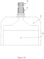
- FIG. 10 generally illustrates an embodiment of a container 131 connected to the cap 10 and with the overcap 70 in place capping the cap 10.
- the container 131 is shown as a pouch in the preferred embodiment depicted in FIG. 10 , but may also comprise a bag, container, bottle, line,, and/or any other container used to hold and/or transport the nutritional composition 132 and/or fluid. Since the container of nutritional composition is deformable, for example when the container 131 is a pouch, a user may squeeze and/or apply pressure to the container 131 to assist in moving the nutritional composition 132 from the container 131 and through the cap 10 or otherwise out of the container 131. In an example not according to claim 16, gravity is used to move the nutritional composition 132 from the container 131 and through the cap 10 or otherwise out of the container 131.
- a configuration where the container 131 is squeezed may move the nutritional composition 132 from the pouch more quickly than using conventional, gravity fed techniques.
- the container 131 may be squeezable and tight connections between the container 131, cap 10, and a patient line are advantageous in reducing spillage of the contents from the container 131.
- the cap 10 connects directly to an enteral line feeding tube (not shown), without the use of a giving set, administration set or other adaptor.
- the cap 10 may only be partially screwed onto the container 131.
- the cap 10 and the container 131 may be configured in a tamper-evident configuration, where a user may irreparably break a seal, plastic retainer, foil, or other mechanism that shows that a package no longer has the original seal and/or is no longer sterile.
- the cap 10 and/or the overcap 70 may be attached to the container 131 to break the tamper evident seal.
- overcap 70 may be provided, for example, larger dimensions, extensions (i.e., wings for grabbing by a user) and/or textured surfaces may be provided as part of the overcap 70.
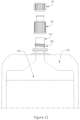
- FIG. 11 generally illustrates an embodiment of the container 131 that is a pouch with a spout 141 comprising pouch spout threads 142, the cap 10, and the overcap 70 in an assembly configuration.
- the pouch spout threads 142 may be configured circumferentially about the spout 141 and configured to receive the lower receiving threads 21 of the lower portion 11 of the cap 10.
- the spout 141 may not be provided with connecting threads 142, and may instead be provided with a clip, snap, plug, fitting and/or other connector for connecting the spout to a corresponding connector element of the lower portion 11 of the cap 10. More or fewer and/or different connecting threads may be manufactured than the connecting threads 142 shown in FIG. 11 .
- the overcap 70 may be configured to screw into the upper portion 12 by engaging the upper connecting threads 13 (as shown in detail in FIGS. 1-7 ) with upper receiving threads of the overcap (not shown) to be rotatably attached to the upper portion 12 of the cap 10.
- a center of the generally cylindrical shape of the overcap 70 may be aligned with the centerline 41, for example the centerline 41 as shown in FIG. 4 , to align the overcap 70 with the upper portion 12 for connecting the upper portion 12 to the overcap 70 using the upper connecting threads 13.
- the upper connecting threads 13 may not be provided, and the overcap 70 may fit onto the upper assembly using, for example, a snap, a hook, and/or a friction coupling.
- the overcap 70 may be a flip-top cap hinged from the upper portion 12 of the cap 10.
- the overcap 70 may be a foil strip positioned across the upper portion 12 of the cap 10.
- the overcap 70 may be configured such that it can be snapped off the upper portion 12 of the cap 10, for example the cap 10 and overcap 70 may be produced as a single element with a weakend portion (such as a zone of thinner material, or a perforated zone) at the interface of the overcap portion 70 and the upper portion 12 of the cap 10, to allow the overcap to be separated (snapped off) from the cap 10.
- a weakend portion such as a zone of thinner material, or a perforated zone
- a central peg may be included in the overcap 70.
- the central peg may extend from a closed end of the overcap 70 along a centerline of the overcap toward an open end of the overcap 70.
- the central peg may aid in closing and/or affixing the overcap 70 to the upper portion 12 of the cap 10.
- the central peg may be used to puncture the strip of foil and/or the seal.
- the overcap 70 may not be provided because the sealing function of the overcap 70 may instead be provided by the strip of foil and/or the seal.
- the spout 141 may be configured with a larger opening than the opening of the cap defined by the upper cavity 51 of the upper portion 12.
- the spout 141 may be configured for oral consumption of the nutritional composition 132, while the cap may be configured to be connected to a patient line, thus optionally requiring different sized openings for different uses.
- the spout 141 and or the cap 10 may be sealed using a plastic, metal, foil, or other seal.
- the seal may indicate whether the container 131 was tampered with if tampering should occur and/or to provided additional sealing protection when shipping the container 131.
- the seal may be provided to ensure the cap 10, the container 131 (e.g., a pouch), and/or the overcap 70 are sterile.
- the overcap 70, the cap 10, and the container 131 are provided in a connected manner which may still allow for a user to screw and/or snap the overcap 70, the cap 10, and the container 131 to each other.
- a retaining line may be provided that connects the cap 10 to the overcap 70 and the container 131.
- the overcap 70 may be hinged from the cap 10.
- the overcap 70, the cap 10, and the container 131 may all be connected to a connecting member that allows each of the overcap 70, the cap 10, and the container 131 to rotate in a connecting portion of the hinged member. Such a configuration may advantageously prevent misplacing or swallowing of the cap 10, overcap 70, and/or other components of a cap-overcap-container system.
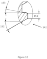
- FIG. 12 generally illustrates a detailed cutaway view of the container spout threads 142 of an embodiment of the spout 141.
- the container spout threads 142 may be defined by a spout thread crest width 151.
- the spout thread crest width 151 may be zero or about zero, which results in a thread that comes to a point.
- the container spout threads 142 may be defined by an upper spout thread half angle 153 and a lower spout thread half angle 152.
- the upper and lower spout thread half angles 153 and 152 may be defined by an angle of an upper or lower portion of a container spout thread 142 thread tooth from a plane substantially perpendicular to a centerline of a substantially cylindrical embodiment of the spout 141. In an embodiment, the upper spout thread half angle 153 and the lower spout thread half angle 152 are equal or about equal. In an embodiment, the upper spout thread half angle 153 and the lower spout thread half angle 152 are not equal or about equal.
- a method for connecting the container 131 to an enteral line may include removing the overcap 70 from the cap 10, where the cap 10 is configured to flow the nutritional composition 132 through the cap 10. "Removing" means that a user can remove the overcap 70 from the cap 10 without using tools and without damaging the overcap 70 and the cap 10.
- the cap 10 may be removably connected to the container 131 and then connected sealingly to the enteral line. "Removably connected” means that that a user can remove the cap 10 from the container 131 without using tools and without damaging the cap 10 and the container 131.
- a pressure may be applied to the container 131 to flow the nutritional composition 132 in the container 131 through the cap 10 and into the enteral line.
- the nutritional composition 132 may be refilled in the container 131 through a refilling opening in the cap 10 and/or through the spout 141.
- a seal may be required to be broken when the overcap 70 is connected to the cap 10 prior to connecting the cap 10 sealingly to the enteral line.
- the method may include disconnecting the cap 10 from the enteral line.
- the method may include resealing the cap 10 by reconnecting the overcap 70 to the cap 10.
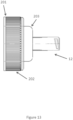
- FIG. 13 illustrates an embodiment of the cap 10 with the upper portion 12.
- the cap 10 may be configured to connect to containers other than the container 131.
- the upper portion 12 of the cap 10 may be provided with a Smartflex cap connection 201.
- the Smartflex cap connection 201 may be configured to connect to a spout of a Smartflex Bottle ® .
- a diameter of the Smartflex cap connection 201 may be larger than a diameter of the upper portion 12.
- a middle portion 203 may be provided.
- the middle portion 203 may be configured to provide a connection between the relatively large diameter of the Smartflex cap connection 201 with the relatively small diameter of the upper portion 12.
- the diameter of the Smartflex cap connection 201 may be closer to the diameter of the upper portion 12, for example within about 10%. In such an embodiment, the middle portion 203 may not be provided, and the Smartflex cap connection 201 may connect directly to the upper portion 12.
- the Smartflex cap connection 201 may be provided with ridges 202.
- the ridges 202 may be configured perpendicularly to a plane defined by a largest cross sectional plane of the Smartflex cap connection 201, as shown in FIG. 13 . Additionally or alternatively, the ridges 202 may be crosshatched, textured, and/or comprised of the same or different material as the rest of the Smartflex cap connection 201. For example, the ridges 202 may be rubber.
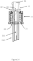
- FIG. 14 illustrates an embodiment of the upper portion 12 comprising the upper cavity 51.
- the upper portion base 42 is configured to be connected to a spike 210.
- the upper portion base 42 may be configured to connect to the lower portion 11 and the spike 210.
- the lower receiving threads 21 may be configured to connect to a spout, for example the spout 141, and allow for the spike 210 to enter the spout 141.
- the spike 210 may be configured to break the seal by piercing the seal when the spike 210 enters the spout 141.
- the spike 210 may be provided with a spike cavity 211.
- the spike cavity 211 may be connected to the transmission opening 61.
- a diameter of the spike cavity 211 corresponds to a diameter of the transmission opening 61 and may reduce any flow restriction between the transmission opening 61 and the spike cavity 210.
- the lower portion 11 is connected to the spout 141 such that the nutritional composition 132 in the container 131 flows from the container 131, into the spike cavity 211, through the transmission opening 61 and into the upper cavity 51.
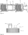
- Figure 15 illustrates an embodiment of the cap 10.
- a second cap 100 is be inserted between the cap 10 and the container 131 (not shown).
- the upper portion 12 of the second cap 100 includes an ENPlus ® (cross) port connector (shown as 210) and the upper portion 12 of the first cap 10 includes an ENFit ® connector (shown as 211).
- the lower portion of the cap 10 comprises a first threaded connection portion positioned in an inner walled section defining a prximal cavity. This frst threaded connection portion being confirgured for connection with a further threaded portion (shown as 13) on the exterior of the upper portion of the cap 100.
- the sequence of the caps 10 and 100 may be inversed.
- Figure 16 illustrates another embodiment of the cap 10 with the upper portion 12 and lower portion 11.
- the upper portion 12 of the cap 10 may include one or more further connection ports / connection elements in addition to the connection element configured for direct connection to the enteral line.
- the upper portion 12 of the cap 10 includes a connection element, shown as 211, configured for direct connection to an enteral line and a second connection element, shown as 210, configured as an ENPlus ® (cross) port connector, for connection with an administration set or giving set.
- connection element or connection port may alternatively be configured as another type of connector or port, and may be used as an alternative means to connect the pouch/bottle to a feeding tube, or, for example, as a port allowing introduction of a syringe or tube for addition of a medicament or additive to the nutritional composition, or for introducing water to flush the system.
- a method of making a cap for a container may comprise forming: the cap to have a cylindrical section comprising a proximal end and a distal end; a proximal cavity comprising an inlet opening positioned within the proximal end of the cylindrical section; a distal cavity comprising an outlet opening positioned within the distal end of the cylindrical section; a transmission portion positioned between the proximal cavity and the distal cavity; a first threaded connection positioned around an inner circumference of a walled section defining the proximal cavity; and a second threaded connection positioned around an outer circumference of the distal end of the cylindrical section.
- the method can comprise injection molding and/or extrusion.
- a method of making a package closure system may comprise molding: a package outlet comprising a first connection element; a cap configured to removably connect to the package outlet using the first connection element and comprising a second connection element; and an ENFit ® connector and/or overcap configured to removably connect to the cap using the second connection element.
Landscapes
- Health & Medical Sciences (AREA)
- Life Sciences & Earth Sciences (AREA)
- Veterinary Medicine (AREA)
- Public Health (AREA)
- General Health & Medical Sciences (AREA)
- Animal Behavior & Ethology (AREA)
- Pharmacology & Pharmacy (AREA)
- Engineering & Computer Science (AREA)
- Hematology (AREA)
- Heart & Thoracic Surgery (AREA)
- Biomedical Technology (AREA)
- Anesthesiology (AREA)
- Vascular Medicine (AREA)
- Physics & Mathematics (AREA)
- Fluid Mechanics (AREA)
- Mechanical Engineering (AREA)
- Closures For Containers (AREA)
- Medical Preparation Storing Or Oral Administration Devices (AREA)
Description
- The present disclosure generally relates to health and nutrition. More specifically, the present disclosure relates to enteral nutrition container cap devices and methods of making and using the enteral nutrition container caps.
- The delivery of nutritional compositions to mammals, such as human patients, that cannot orally ingest food or other forms of nutrition is often of critical importance. For example, enteral bottles and containers having feeding tubes that deposit food directly into the gastrointestinal tract at a point below the mouth are often used to sustain life while a patient is unable, or refuses, to take food orally. Bottles and containers, feeding tubes and other artificial delivery systems and routes can be used temporarily during the treatment of acute medical conditions. For chronic medical conditions, such systems and routes can be used as part of a treatment regimen that lasts for the remainder of a patient's life. No matter the duration of use, these devices often provide the only means for feeding the patient.
- Common concerns with the enteral feeding of nutritional compositions are connection quality and spillage when connecting a container to a feeding device. Some nutritional compositions may be dual use, so another common concern is to provide a container that may be used for consumption both orally and as enteral nutrition. A common method to deliver nutritional compositions to a patient is to pour the nutritional composition from a container into an open syringe attached to a feeding tube. Such methods may be difficult for children or patients with fine motor skills challenges. As a result, the nutritional composition may spill out of the open syringe attached to a feeding tube.
-
WO 2004/045705 discloses a connector device suitable for connecting an enteral administration set to a laminated paper packaging system comprising enterally administrable medical or nutritional food. -
WO 2018/067629 discloses a syringe having a barrel and a non-luer tip that is not connectable to an intravenous device. The syringe has an enteral collar having a distal end and proximal end, the proximal end having a syringe engagement feature. The enteral collar is sized to permit an ENFit connection to an enteral device and prevent connection to a device having a luer connector. - The present disclosure provides advantages and solutions to problems in existing technologies for connecting enteral containers to enteral feeding tubes. A package closure system is provided according to claim 1. A method for providing a nutritional composition is provided according to claim 15.
-
-
FIG. 1 illustrates a perspective view of an embodiment of a cap according to the present disclosure. -
FIG. 2 illustrates a view of a lower portion of an embodiment of the cap according to the present disclosure. -
FIG. 3 illustrates a view of an upper portion and the lower portion of an embodiment of the cap according to the present disclosure. -
FIG. 4 illustrates a side view of the upper portion and the lower portion of an embodiment of the cap according to the present disclosure. -
FIG. 5 illustrates a cutaway view of the upper portion and the lower portion of an embodiment of the cap according to the present disclosure. -
FIG. 6 illustrates a cutaway view of the upper portion of an embodiment of the cap according to the present disclosure. -
FIG. 7 illustrates a side view of an embodiment of the upper portion of an embodiment of the cap according to the present disclosure. -
FIG. 8 illustrates an isometric view of the upper portion of an embodiment of the cap according to the present disclosure. -
FIG. 9 illustrates a through-cavity view of the upper portion of an embodiment of the cap according to the present disclosure. -
FIG. 10 illustrates an embodiment of a pouch, the cap, and the overcap in a connected configuration according to the present disclosure. -
FIG. 11 illustrates an embodiment of the pouch with a spout, the cap, and the overcap in an assembly configuration according to the present disclosure. -
FIG. 12 illustrates a detail view of an embodiment of pouch spout threads according to the present disclosure. -
FIG. 13 illustrates an embodiment of a cap according to the present disclosure. -
FIG. 14 illustrates an embodiment of a cap provided with a spike according to the present disclosure. -
FIG. 15 and 16 illustrate two further examples of caps. - Detailed embodiments of devices and methods are disclosed herein. However, it is to be understood that the disclosed embodiments are merely exemplary of the devices and methods, which may be embodied in various forms. Therefore, specific functional details disclosed herein are not to be interpreted as limiting, but merely as a basis for the claims as a representative example for teaching one skilled in the art to variously employ the present disclosure.
- As used herein, "about," "approximately" and "substantially" are understood to refer to numbers in a range of numerals, for example the range of -10% to +10% of the referenced number, preferably -5% to +5% of the referenced number, more preferably -1% to +1% of the referenced number, most preferably -0.1% to +0.1% of the referenced number. All numerical ranges herein should be understood to include all integers, whole or fractions, within the range. Moreover, these numerical ranges should be construed as providing support for a claim directed to any number or subset of numbers in that range. For example, a disclosure of from 1 to 10 should be construed as supporting a range of from 1 to 8, from 3 to 7, from 1 to 9, from 3.6 to 4.6, from 3.5 to 9.9, and so forth.
- The preferred embodiments relate to a cap or connector methods and devices for connecting a container containing nutritional compositions to an enteral feeding device, where the cap or connector may also be used for oral ingestion of the nutritional compositions.
-
FIG. 1 generally illustrates an embodiment of acap 10. Thecap 10 can comprise: anupper portion 12 for connecting to an external receiving member and/or anovercap 70 as shown inFIGS. 10 and11 ; and alower portion 11 for connecting to acontainer 131. Referring back toFIG. 1 , the external receiving member may be a male ENFit® connector. In an embodiment a female ENFit® connector positioned on theupper portion 12 of thecap 10 may be connected to the male ENFit® connector of the external receiving member. In an alternative embodiment (not shown inFigure 1 ) the external connector may be a female ENFit® connector, and theupper portion 12 of thecap 10 may be configured as a male ENFit® connector, for connecting to the female ENFit ® connector of the external receiving member. Thecap 10 may be provided withouter ridges 14 along an outer circumference of thelower portion 11. Theouter ridges 14 may be configured to assist a user when removing, manipulating and/or attaching the cap to other systems or devices. For example, thecap 10 may screw onto other devices containing nutritional product (e.g., a flexible pouch, a SmartFlex Bottle®, a water bottle, a Resource Junior® bottle, an Infrasource® bottle, Tetra® Bottle, other NHSc bottles, and/or other bottles known in the art). Although not shown inFIG. 1 , other features of thecap 10 may be provided, for example, larger dimensions, extensions (i.e., wings for grabbing by a user) and/or textured surfaces may be provided as part of thecap 10. - The
cap 10 thereby provides direct connection of acontainer 131 for a nutitional composition with an enteral line feeding tube, without the use of a giving set, administration set or other adaptor. - The
outer ridges 14 may be configured perpendicularly to a plane defined by a smallest cross sectional plane of thecap 10, as shown inFIG. 1 . Additionally or alternatively, theouter ridges 14 may be crosshatched, textured, and/or comprised of the same or different material as the rest of thecap 10. For example, theouter ridges 14 may be rubber. - The
cap 10 may be provided with upper connectingthreads 13 extending from theupper portion 12. The upper connectingthreads 13 may be configured to attach to an ENFit® connector. In an embodiment, thecap 10 may not be provided with connectingthreads 13, and may instead be provided with a clip, snap, plug, fitting and/or other connector for connecting thecap 10 to an external receiving member. More or fewer and/or different connecting threads may be manufactured than the connectingthreads 13 shown inFIG. 1 . In an embodiment, thecap 10 may only partially comply with ENFit® connector standards. For example, thecap 10 may be provided with a larger bore size than that provided in the ENFit® connector standards to reduce any flow restriction through thecap 10. - The
cap 10, as well as connecting components such as theovercap 70, shown inFIGS. 10 and11 , may be manufactured from materials including, but not limited to plastics, sustainable plastics, glass, metal, paper, fiber, carton, edible materials (e.g., fiber, sugar, chews, etc.) and combinations thereof. Thecap 10 may be configured to indicate a temperature, a pH, and/or other parameter of anutritional composition 132, shown inFIG. 10 ; for example, by manufacturing thecap 10 from a material responsive to the temperature and/or the pH. The color of thecap 10 may correlate to a use for thenutritional composition 132; for example, a cap color may correlate to an embodiment of thenutritional composition 132 where thenutritional composition 132 is optimized to fulfill a specific nutritional requirement. Thecap 10 may be manufactured from a flexible material, enabling thecap 10 to be used as a straw. Thecap 10 may be manufactured from a transparent material or comprise a transparent section to enable the observation of thenutritional composition 132 flowing through thecap 10. -
FIG. 2 generally illustrates a view of thelower portion 11 of thecap 10. The upper connectingthreads 13 are shown, as well as theouter ridges 14.FIG. 2 showslower receiving threads 21, which may be positioned within alower cavity 22 of thecap 10. Thelower receiving threads 21 may be configured to attach to thecontainer 131, thereby engaging thecontainer 131 and allowing thenutritional composition 132 to flow from thecontainer 131, into thelower cavity 22, and through other portions of thecap 10. -
FIG. 3 generally illustrates an isometric view of thecap 10, which may include: theupper portion 12 with the upper connectingthreads 13; and thelower portion 11 with theouter ridges 14. -
FIG. 4 generally illustrates a side view of thecap 10, which may include: theupper portion 12 with the upper connectingthreads 13; and thelower portion 11 with theouter ridges 14. Acenterline 41 is shown for reference, which passes through a midline of the generally cylindrical structure of thecap 10. Anupper portion base 42 may provide an interface between theupper portion 12 and thelower portion 11. Alower portion base 43 is shown, which can be positioned on the distal end of thelower portion 11 from theupper portion 12. - In an embodiment, a portion of the
cap 10 between theupper portion base 42 and theridges 14 may be elongated to be used as a straw and/or to be more easily manipulated by a user. Such an embodiment may provide better ergonomics and/or better visibility to material flowing through thecap 10 if thecap 10 is manufactured from a transparent material. - In an embodiment, the
upper portion 12 of thecap 10 may be retractable, i.e. theupper portion 12 withsecond connection element 13 may reversible retract, partially or fully, into thecavity 22 oflower portion 11. -
FIG. 5 generally illustrates a cutaway view of theupper portion 12 and thelower portion 11 of thecap 10. As shown, thecap 10 includes anupper cavity 51 that connects to thelower cavity 22, also shown inFIG. 2 . Referring back toFIG. 5 , thelower receiving threads 21 may extend around an inner circumference of thelower portion 11. Thelower receiving threads 21 may extend through thelower portion base 43 to aid the lower portion 11 (e.g., the lower receiving threads 21) in connecting to another connection member. -
FIG. 6 generally illustrates a dimensioned cutaway view of theupper portion 12 of thecap 10, wherein theupper portion 12 of thecap 10 is adapted for ENFit® compatibility. Theupper cavity 51 is shown, which may extend through theupper portion 12 along thecenterline 41. Theupper cavity 51 may be defined by an upper portioninner wall 62, and have an upper portion inner wall diameter ØD and an upper portion length above base E.A transmission opening 61 may be provided at a distal end of theupper portion 12 from the upper connectingthreads 13. Thetransmission opening 61 may be defined by a transmission opening diameter ØU. - As shown in
FIG. 6 , the transmission opening diameter ØU may be smaller than an upper portion base inner diameter ØG. In a configuration where the transmission opening diameter ØU is smaller than the upper portion base inner diameter ØG, the transmission opening diameter ØU may create a flow restriction for thenutritional composition 132 flowing through theupper portion 12. In an interface between the upper portion base inner diameter ØG and the transmission opening diameter ØU, a transmission opening chamfer angle T3 may be configured to throttle the flow restriction to adjust flow characteristics, for example flow speed and/or turbulence. In an embodiment, the upper portion base inner diameter ØG and the transmission opening diameter ØU may be equal or about equal, therefore eliminating the flow restriction and resulting in the transmission opening chamfer angle T3 being 90° or about 90°. - The
upper portion 12 may comprise an upper portion diameter ØJ, which may correspond to a diameter of the outer walls of theupper portion 12. In an embodiment, the upper connectingthreads 13 extend beyond the upper portion diameter ØJ. The upper connectingthreads 13 may have an upper connecting threads diameter ØH around thecenterline 41, where the upper portion diameter ØJ is smaller than the upper connecting threads diameter ØH. - The upper connecting
threads 13 may have a thread crest width M and a thread pitch width N, where the thread pitch width N is preferably a widest point of the upper connectingthreads 13. The upper connectingthreads 13 may contact theupper portion 12 at the widest point of the upper connectingthreads 13. The upper connectingthreads 13 may then taper to the most distal portion of the upper connectingthreads 13, which may have the thread crest width M. In an embodiment where the upper connectingthreads 13 taper to a point, the thread crest width M may be zero or about zero. In an embodiment, the pitch thread width N and the thread crest width M may be equal or about equal, resulting in the upper connectingthreads 13 being un-tapered (i.e., straight-cut). - In an embodiment, the relative proportions given in
FIG. 6 may be varied to meet different user needs. For example, the upper portion length above base E may be elongated to allow thecap 10 to be used as a straw and/or more easily manipulated by a user. In an embodiment, the upper portion diameter ØJ may be much larger to allow a user to apply more torque to thecap 10 when screwing thecap 10 into a device and/or a component. In an embodiment, the upper portion inner wall diameter ØD may be optimized for a desired flow rate though thecap 10. In an embodiment, the dimensions including at least the thread crest width M, the thread pitch width N and the upper connecting threads diameter ØH may be adapted for connecting to a specific device and/or a specific component. - In an embodiment, the
cap 10 may include a strip of foil and/or a seal across the upper portion inner wall diameter ØD. The strip of foil and/or the seal can signal to a user that thecap 10, thecontainer 131, and/or other structure has been tampered with. The strip of foil and/or the seal may also provide added protection against leaks when shipping and/or handling thecontainer 131. -
FIG. 7 generally illustrates a side view of an embodiment of theupper portion 12 of thecap 10. Theupper portion 12 is shown with upper connectingthreads 13. Theupper portion 12 may generally be defined by a base width ØW, a top width ØF3 and a length above base R3. Theupper portion 12 may includechamfers 73 at an opposite end from thebase portion 42 along thecenterline 41, and thechamfers 73 may be defined by a chamfer height C. -
FIG. 8 generally illustrates an isometric view of theupper portion 12 of thecap 10, adapted for ENFit® compatibility. Theupper portion 12 may include upper connectingthreads 13, which may extend radially outward from the center of the generally cylindrical structure of theupper portion 12. Theupper connection threads 13 may be positioned in a plane offset from a plane defined by theupper portion base 42. As the upper connectingthreads 13 extend upward, the threads may terminate at an upper connecting thread terminus edge width X3. The upper connecting thread terminus edge width X3 may be provided to prevent misconnection of thecap 10. A configuration of theupper portion 12 may comprise an embodiment of the upper connecting thread terminus edge width X3 where the upper connecting thread terminus edge width X3 is maximized because the contact area provided by a longer embodiment of the upper connecting thread terminus edge width X3 may provide a larger sealing area. -
FIG. 9 generally illustrates a through-cavity view of theupper portion 12 of an embodiment of thecap 10. The view shown inFIG. 9 is a view generally down thecenterline 41 and shows theupper cavity 51 defined by the upper portioninner wall 62. Theupper cavity 51 may terminate into thetransmission opening 61, which may provide a path into thelower cavity 22, as shown inFIG. 2 . Referring back toFIG. 9 , thetransmission opening 61 is shown as generally circular, but may be other configurations, for example another geometric shape. Thetransmission opening 61 may also vary in cross section along thecenterline 41, for example thetransmission opening 61 may increase and/or decrease in diameter along thecenterline 41. - The upper connecting
threads 13 may protrude from a part of theupper portion 12 that defines theinner cavity 51. The upper connectingthreads 13 are shown with an upper connecting thread width γ which does not extend around the entire circumference of theupper portion 12. In an embodiment, the upper connecting thread width γ may extend around more or less of the circumference of theupper portion 12. An edge of the upper connectingthreads 13 may terminate at an upper connecting thread chamfer angle Z3. The upper connecting thread chamfer angle Z3 may be defined as an angle from: a first vector extending from a point defined by thecenterline 41 in a plane perpendicular to thecenterline 41; and a second vector defined from a locus along the first vector, the second vector extending from the locus. - The upper connecting thread terminus edge width X3 is also shown. The upper connecting thread terminus edge width X3 may be defined as a function of a thread pitch, a thread depth, and a number of threads per unit of distance along the
centerline 41. -
FIG. 10 generally illustrates an embodiment of acontainer 131 connected to thecap 10 and with theovercap 70 in place capping thecap 10. - The
container 131 is shown as a pouch in the preferred embodiment depicted inFIG. 10 , but may also comprise a bag, container, bottle, line,, and/or any other container used to hold and/or transport thenutritional composition 132 and/or fluid. Since the container of nutritional composition is deformable, for example when thecontainer 131 is a pouch, a user may squeeze and/or apply pressure to thecontainer 131 to assist in moving thenutritional composition 132 from thecontainer 131 and through thecap 10 or otherwise out of thecontainer 131. In an example not according to claim 16, gravity is used to move thenutritional composition 132 from thecontainer 131 and through thecap 10 or otherwise out of thecontainer 131. A configuration where thecontainer 131 is squeezed may move thenutritional composition 132 from the pouch more quickly than using conventional, gravity fed techniques. When thenutritional composition 132 is required for use as a bolus, for example when a bolus of liquid is required, thecontainer 131 may be squeezable and tight connections between thecontainer 131,cap 10, and a patient line are advantageous in reducing spillage of the contents from thecontainer 131. - The
cap 10 connects directly to an enteral line feeding tube (not shown), without the use of a giving set, administration set or other adaptor. - In an embodiment, the
cap 10 may only be partially screwed onto thecontainer 131. Thecap 10 and thecontainer 131 may be configured in a tamper-evident configuration, where a user may irreparably break a seal, plastic retainer, foil, or other mechanism that shows that a package no longer has the original seal and/or is no longer sterile. In an embodiment, thecap 10 and/or theovercap 70 may be attached to thecontainer 131 to break the tamper evident seal. - Although not shown in
FIG. 10 , other features of theovercap 70 may be provided, for example, larger dimensions, extensions (i.e., wings for grabbing by a user) and/or textured surfaces may be provided as part of theovercap 70. -
FIG. 11 generally illustrates an embodiment of thecontainer 131 that is a pouch with aspout 141 comprisingpouch spout threads 142, thecap 10, and theovercap 70 in an assembly configuration. Thepouch spout threads 142 may be configured circumferentially about thespout 141 and configured to receive thelower receiving threads 21 of thelower portion 11 of thecap 10. In an embodiment, thespout 141 may not be provided with connectingthreads 142, and may instead be provided with a clip, snap, plug, fitting and/or other connector for connecting the spout to a corresponding connector element of thelower portion 11 of thecap 10. More or fewer and/or different connecting threads may be manufactured than the connectingthreads 142 shown inFIG. 11 . - The
overcap 70 may be configured to screw into theupper portion 12 by engaging the upper connecting threads 13 (as shown in detail inFIGS. 1-7 ) with upper receiving threads of the overcap (not shown) to be rotatably attached to theupper portion 12 of thecap 10. - When the
overcap 70 is placed over theupper portion 12, a center of the generally cylindrical shape of theovercap 70 may be aligned with thecenterline 41, for example thecenterline 41 as shown inFIG. 4 , to align theovercap 70 with theupper portion 12 for connecting theupper portion 12 to theovercap 70 using the upper connectingthreads 13. In an embodiment, the upper connectingthreads 13 may not be provided, and theovercap 70 may fit onto the upper assembly using, for example, a snap, a hook, and/or a friction coupling. In an embodiment, theovercap 70 may be a flip-top cap hinged from theupper portion 12 of thecap 10. In an embodiment, theovercap 70 may be a foil strip positioned across theupper portion 12 of thecap 10. In an embodiment theovercap 70 may be configured such that it can be snapped off theupper portion 12 of thecap 10, for example thecap 10 andovercap 70 may be produced as a single element with a weakend portion (such as a zone of thinner material, or a perforated zone) at the interface of theovercap portion 70 and theupper portion 12 of thecap 10, to allow the overcap to be separated (snapped off) from thecap 10. - In an embodiment, a central peg may be included in the
overcap 70. The central peg may extend from a closed end of theovercap 70 along a centerline of the overcap toward an open end of theovercap 70. The central peg may aid in closing and/or affixing theovercap 70 to theupper portion 12 of thecap 10. In an embodiment where theupper portion 12 has the strip of foil and/or the seal across the upper portion inner wall diameter ØD (the upper portion inner wall diameter ØD is labeled inFIG. 6 ), the central peg may be used to puncture the strip of foil and/or the seal. In an embodiment where theupper portion 12 has the strip of foil and/or the seal across the upper portion inner wall diameter ØD, theovercap 70 may not be provided because the sealing function of theovercap 70 may instead be provided by the strip of foil and/or the seal. - The
spout 141 may be configured with a larger opening than the opening of the cap defined by theupper cavity 51 of theupper portion 12. Thespout 141 may be configured for oral consumption of thenutritional composition 132, while the cap may be configured to be connected to a patient line, thus optionally requiring different sized openings for different uses. - In an embodiment, the
spout 141 and or thecap 10 may be sealed using a plastic, metal, foil, or other seal. The seal may indicate whether thecontainer 131 was tampered with if tampering should occur and/or to provided additional sealing protection when shipping thecontainer 131. The seal may be provided to ensure thecap 10, the container 131 (e.g., a pouch), and/or theovercap 70 are sterile. - In an embodiment, the
overcap 70, thecap 10, and the container 131 (e.g., a pouch) are provided in a connected manner which may still allow for a user to screw and/or snap theovercap 70, thecap 10, and thecontainer 131 to each other. For example, a retaining line may be provided that connects thecap 10 to theovercap 70 and thecontainer 131. In an embodiment, theovercap 70 may be hinged from thecap 10. In an embodiment, theovercap 70, thecap 10, and thecontainer 131 may all be connected to a connecting member that allows each of theovercap 70, thecap 10, and thecontainer 131 to rotate in a connecting portion of the hinged member. Such a configuration may advantageously prevent misplacing or swallowing of thecap 10,overcap 70, and/or other components of a cap-overcap-container system. -
FIG. 12 generally illustrates a detailed cutaway view of thecontainer spout threads 142 of an embodiment of thespout 141. Thecontainer spout threads 142 may be defined by a spoutthread crest width 151. In an embodiment, the spoutthread crest width 151 may be zero or about zero, which results in a thread that comes to a point. Thecontainer spout threads 142 may be defined by an upper spoutthread half angle 153 and a lower spoutthread half angle 152. The upper and lower spout thread half angles 153 and 152 may be defined by an angle of an upper or lower portion of acontainer spout thread 142 thread tooth from a plane substantially perpendicular to a centerline of a substantially cylindrical embodiment of thespout 141. In an embodiment, the upper spoutthread half angle 153 and the lower spoutthread half angle 152 are equal or about equal. In an embodiment, the upper spoutthread half angle 153 and the lower spoutthread half angle 152 are not equal or about equal. - In an embodiment, a method for connecting the
container 131 to an enteral line may include removing theovercap 70 from thecap 10, where thecap 10 is configured to flow thenutritional composition 132 through thecap 10. "Removing" means that a user can remove theovercap 70 from thecap 10 without using tools and without damaging theovercap 70 and thecap 10. - The
cap 10 may be removably connected to thecontainer 131 and then connected sealingly to the enteral line. "Removably connected" means that that a user can remove thecap 10 from thecontainer 131 without using tools and without damaging thecap 10 and thecontainer 131. - A pressure may be applied to the
container 131 to flow thenutritional composition 132 in thecontainer 131 through thecap 10 and into the enteral line. Thenutritional composition 132 may be refilled in thecontainer 131 through a refilling opening in thecap 10 and/or through thespout 141. In an embodiment, a seal may be required to be broken when theovercap 70 is connected to thecap 10 prior to connecting thecap 10 sealingly to the enteral line. The method may include disconnecting thecap 10 from the enteral line. The method may include resealing thecap 10 by reconnecting theovercap 70 to thecap 10. -
FIG. 13 illustrates an embodiment of thecap 10 with theupper portion 12. In an embodiment, thecap 10 may be configured to connect to containers other than thecontainer 131. For example, in the embodiment according toFIG. 13 , theupper portion 12 of thecap 10 may be provided with aSmartflex cap connection 201. TheSmartflex cap connection 201 may be configured to connect to a spout of a Smartflex Bottle®. A diameter of theSmartflex cap connection 201 may be larger than a diameter of theupper portion 12. In such an embodiment, amiddle portion 203 may be provided. Themiddle portion 203 may be configured to provide a connection between the relatively large diameter of theSmartflex cap connection 201 with the relatively small diameter of theupper portion 12. In an embodiment, the diameter of theSmartflex cap connection 201 may be closer to the diameter of theupper portion 12, for example within about 10%. In such an embodiment, themiddle portion 203 may not be provided, and theSmartflex cap connection 201 may connect directly to theupper portion 12. - In an embodiment, the
Smartflex cap connection 201 may be provided withridges 202. Theridges 202 may be configured perpendicularly to a plane defined by a largest cross sectional plane of theSmartflex cap connection 201, as shown inFIG. 13 . Additionally or alternatively, theridges 202 may be crosshatched, textured, and/or comprised of the same or different material as the rest of theSmartflex cap connection 201. For example, theridges 202 may be rubber. -
FIG. 14 illustrates an embodiment of theupper portion 12 comprising theupper cavity 51. In the embodiment according toFIG. 14 , theupper portion base 42 is configured to be connected to aspike 210. Theupper portion base 42 may be configured to connect to thelower portion 11 and thespike 210. In such an embodiment, thelower receiving threads 21 may be configured to connect to a spout, for example thespout 141, and allow for thespike 210 to enter thespout 141. In an embodiment where thespout 141 is sealed, thespike 210 may be configured to break the seal by piercing the seal when thespike 210 enters thespout 141. - The
spike 210 may be provided with aspike cavity 211. Thespike cavity 211 may be connected to thetransmission opening 61. As shown inFIG. 14 , a diameter of thespike cavity 211 corresponds to a diameter of thetransmission opening 61 and may reduce any flow restriction between thetransmission opening 61 and thespike cavity 210. In an embodiment, thelower portion 11 is connected to thespout 141 such that thenutritional composition 132 in thecontainer 131 flows from thecontainer 131, into thespike cavity 211, through thetransmission opening 61 and into theupper cavity 51. -
Figure 15 illustrates an embodiment of thecap 10. In the embodiment illustrated in Fugure 15 asecond cap 100 is be inserted between thecap 10 and the container 131 (not shown). In the embodiment illustrated inFigure 15 theupper portion 12 of thesecond cap 100 includes an ENPlus® (cross) port connector (shown as 210) and theupper portion 12 of thefirst cap 10 includes an ENFit® connector (shown as 211). In the embodiment illustrated inFigure 15 the lower portion of thecap 10 comprises a first threaded connection portion positioned in an inner walled section defining a prximal cavity. This frst threaded connection portion being confirgured for connection with a further threaded portion (shown as 13) on the exterior of the upper portion of thecap 100. In an embodiment, the sequence of thecaps -
Figure 16 illustrates another embodiment of thecap 10 with theupper portion 12 andlower portion 11. In an embodiment theupper portion 12 of thecap 10 may include one or more further connection ports / connection elements in addition to the connection element configured for direct connection to the enteral line. For example, in the embodiment according toFigure 16 , theupper portion 12 of thecap 10 includes a connection element, shown as 211, configured for direct connection to an enteral line and a second connection element, shown as 210, configured as an ENPlus® (cross) port connector, for connection with an administration set or giving set. The second connection element or connection port may alternatively be configured as another type of connector or port, and may be used as an alternative means to connect the pouch/bottle to a feeding tube, or, for example, as a port allowing introduction of a syringe or tube for addition of a medicament or additive to the nutritional composition, or for introducing water to flush the system. - In an embodiment, a method of making a cap for a container may comprise forming: the cap to have a cylindrical section comprising a proximal end and a distal end; a proximal cavity comprising an inlet opening positioned within the proximal end of the cylindrical section; a distal cavity comprising an outlet opening positioned within the distal end of the cylindrical section; a transmission portion positioned between the proximal cavity and the distal cavity; a first threaded connection positioned around an inner circumference of a walled section defining the proximal cavity; and a second threaded connection positioned around an outer circumference of the distal end of the cylindrical section. The method can comprise injection molding and/or extrusion.
- A method of making a package closure system may comprise molding: a package outlet comprising a first connection element; a cap configured to removably connect to the package outlet using the first connection element and comprising a second connection element; and an ENFit® connector and/or overcap configured to removably connect to the cap using the second connection element.
Claims (20)
- A package closure system comprising:a deformable package [131] housing a nutritional composition [132];a spout [141] extending from the package, the spout comprising a first connection element [142]; anda cap [10] comprising a channel [22, 51], configured to removably connect directly to the first connection element, and comprising a second connection element [13], the second connection element configured to connect to an enteral line to position the channel leading from the spout to the enteral line such that the cap indirectly connects the spout to the enteral line by the channel, wherein the second connection element is an ENFit® connector.
- The system according to claim 1, wherein the first connection element comprises a first threaded connection element [142], and
the second connection element comprises a second threaded connection element [13]. - The system according to any one of claims 1 to 2, further comprising an overcap [70], the overcap configured to close the channel of the cap.
- The system according to claim 3, wherein the cap is configured to be disconnectable from the spout,wherein the overcap is configured to be disconnectable from the cap, andwherein the overcap, the cap, and the spout maintain a physical connection when the cap is disconnected from the spout and the overcap is disconnected from the cap.
- The system according to claim 3 or 4, comprising a hinged connection by which the overcap is connected to the cap.
- The system according to any one of claims 1 to 5, further comprising an anti-tamper element, the anti-tamper element is configured to be broken when the cap is disconnected from the spout.
- The system according to any one of claims 1 to 6, wherein the cap comprises a spike [210], the spike configured to extend into the spout when the cap is connected to the spout.
- The system according to any one of claims 1 to 7, wherein the channel comprises an upper cavity [51] and a lower cavity [22], and a flow restriction is positioned in the channel and between the upper cavity and the lower cavity.
- The system according to any one of claims 1 to 8, wherein the cap comprises a transparent material.
- The system according to any one of claims 1 to 9, wherein the cap comprises ridges [14, 202] positioned around a circumference of a substantially cylindrical section of the cap.
- The system according to any one of claims 1 to 10, wherein a foil strip is configured to seal the channel of the cap.
- The system according to any one of claims 1 to 11, wherein a foil strip is configured to seal the spout [141] of the deformable package [131].
- The system according to claim 3, wherein a foil strip is configured to seal the overcap.
- The system according to claim 1, wherein the cap comprises an upper portion [12] and a lower portion [11], and wherein the upper portion comprises one or more further connection elements in addition to the second connection element.
- A method of using the package closure system of any one of claims 1 to 14, for providing a nutritional composition from the deformable package to an enteral line, the method comprising:connecting the cap sealingly to the enteral line, wherein the channel extends through one side of the cap to the opposite side of the cap, the cap removably connected to the deformable package; andapplying a pressure to the deformable package to direct the nutritional composition from the deformable package through the channel and into the enteral line.
- The method according to claim 15, further comprising removing an overcap from the cap prior to connecting the cap sealingly to the enteral line.
- The method according to claim 15, further comprising refilling the deformable package through a refilling opening provided in the cap and distinct from the channel.
- The method according to claim 15, further comprising breaking a seal positioned on the cap to seal the cap prior to connecting the cap sealingly to the enteral line.
- The method according to claim 15, further comprising:disconnecting the cap from the enteral line; andsealing the cap by connecting an overcap to the cap.
- The method according to claim 15, further comprising removing the cap from a spout positioned on the deformable package, the spout is configured for oral administration of the nutritional composition through the spout.
Priority Applications (1)
| Application Number | Priority Date | Filing Date | Title |
|---|---|---|---|
| EP24176763.1A EP4397295A1 (en) | 2018-12-21 | 2019-12-20 | Enteral nutrition container cap and methods of making and using the cap |
Applications Claiming Priority (2)
| Application Number | Priority Date | Filing Date | Title |
|---|---|---|---|
| US201862783696P | 2018-12-21 | 2018-12-21 | |
| PCT/EP2019/086820 WO2020128056A1 (en) | 2018-12-21 | 2019-12-20 | Enteral nutrition container cap and methods of making and using the cap |
Related Child Applications (3)
| Application Number | Title | Priority Date | Filing Date |
|---|---|---|---|
| EP24176763.1A Division-Into EP4397295A1 (en) | 2018-12-21 | 2019-12-20 | Enteral nutrition container cap and methods of making and using the cap |
| EP24176763.1A Division EP4397295A1 (en) | 2018-12-21 | 2019-12-20 | Enteral nutrition container cap and methods of making and using the cap |
| EP23173716.4 Division-Into | 2023-05-16 |
Publications (2)
| Publication Number | Publication Date |
|---|---|
| EP3897509A1 EP3897509A1 (en) | 2021-10-27 |
| EP3897509B1 true EP3897509B1 (en) | 2025-03-12 |
Family
ID=69156395
Family Applications (2)
| Application Number | Title | Priority Date | Filing Date |
|---|---|---|---|
| EP24176763.1A Pending EP4397295A1 (en) | 2018-12-21 | 2019-12-20 | Enteral nutrition container cap and methods of making and using the cap |
| EP19835300.5A Active EP3897509B1 (en) | 2018-12-21 | 2019-12-20 | Enteral nutrition container cap and methods of making and using the cap |
Family Applications Before (1)
| Application Number | Title | Priority Date | Filing Date |
|---|---|---|---|
| EP24176763.1A Pending EP4397295A1 (en) | 2018-12-21 | 2019-12-20 | Enteral nutrition container cap and methods of making and using the cap |
Country Status (8)
| Country | Link |
|---|---|
| US (1) | US20220062104A1 (en) |
| EP (2) | EP4397295A1 (en) |
| JP (3) | JP2022514637A (en) |
| CN (3) | CN119157749A (en) |
| AU (1) | AU2019410752B2 (en) |
| CA (1) | CA3124277A1 (en) |
| ES (1) | ES3030111T3 (en) |
| WO (1) | WO2020128056A1 (en) |
Families Citing this family (9)
| Publication number | Priority date | Publication date | Assignee | Title |
|---|---|---|---|---|
| US20220062104A1 (en) * | 2018-12-21 | 2022-03-03 | Societe Des Produits Nestle S.A. | Enteral nutrition container cap and methods of making and using the cap |
| GB202000444D0 (en) * | 2020-01-13 | 2020-02-26 | Gbuk Group Ltd | Tamper evident cap |
| US12576008B2 (en) * | 2020-04-16 | 2026-03-17 | Scholle Ipn Corporation | Flexible container assembly and fitment assembly for a flexible container assembly |
| US11918540B2 (en) * | 2020-04-23 | 2024-03-05 | Vonco Products, Llc | Cap for spout and modified spout |
| EP4699640A3 (en) * | 2020-08-17 | 2026-05-06 | LactaLogics, Inc. | Enteral feeding system |
| JP7639599B2 (en) * | 2021-07-28 | 2025-03-05 | 株式会社ジェイ・エム・エス | adapter |
| IT202200002975A1 (en) * | 2022-02-17 | 2023-08-17 | Guala Pack Spa | CLOSURE FOR A STRAW OF A THIN-WALLED PACKAGING |
| KR102606788B1 (en) * | 2022-07-15 | 2023-11-29 | 대상웰라이프 주식회사 | A connector that engages the pouch spout |
| JPWO2024157521A1 (en) * | 2023-01-26 | 2024-08-02 |
Citations (12)
| Publication number | Priority date | Publication date | Assignee | Title |
|---|---|---|---|---|
| FR2759593A1 (en) | 1997-02-14 | 1998-08-21 | Gervais Danone Co | Instrument tip for extracting liquid from sealed container |
| EP1112943A1 (en) | 1998-06-11 | 2001-07-04 | Tetra Laval Holdings & Finance SA | Container with cap |
| WO2004045705A1 (en) | 2002-11-18 | 2004-06-03 | Novartis Ag | Connector device |
| US20070112323A1 (en) | 2005-10-20 | 2007-05-17 | Sherwood Services Ag | Enteral Feeding Set |
| US20120310177A1 (en) | 2009-12-10 | 2012-12-06 | Fresenius Kabi Deutschland Gmbh | Connector system for nutrient containers for enteral nutrition |
| WO2014078404A1 (en) | 2012-11-14 | 2014-05-22 | Abbott Laboratories | Cap suitable for use with enteral feeding container |
| WO2016120318A1 (en) | 2015-01-30 | 2016-08-04 | Pronova Biopharma Norge As | Enteral feeding device |
| WO2018067629A1 (en) * | 2016-10-06 | 2018-04-12 | Becton, Dickinson And Company | Syringe with enteral connection feature |
| WO2018108337A1 (en) | 2016-12-16 | 2018-06-21 | Rockfield Medical Devices Limited | A portable enteral feeding apparatus |
| US20180265238A1 (en) | 2013-12-16 | 2018-09-20 | Kiley Steven Wilson | Flowable food feeding device |
| CA2964537A1 (en) | 2017-04-18 | 2018-10-18 | Medela Holding Ag | Enteral feeding adapter and method of use |
| US20180344570A1 (en) | 2016-02-24 | 2018-12-06 | Neomed, Inc. | Fluid transfer connector |
Family Cites Families (27)
| Publication number | Priority date | Publication date | Assignee | Title |
|---|---|---|---|---|
| US4888008A (en) * | 1987-03-03 | 1989-12-19 | Sherwood Medical Company | Vented spike connection component |
| IT1290079B1 (en) * | 1997-03-14 | 1998-10-19 | Tetra Laval Holdings & Finance | RE-SEALABLE OPENING DEVICE FOR PACKAGING FOR VERSABLE FOOD PRODUCTS |
| JP3889496B2 (en) * | 1997-10-27 | 2007-03-07 | 藤森工業株式会社 | Infusion solution packaging bag |
| EP0947433A1 (en) * | 1998-04-03 | 1999-10-06 | Tetra Laval Holdings & Finance SA | Device for opening packages of pourable food products |
| US6929136B2 (en) * | 2002-01-08 | 2005-08-16 | Fabricas Monterrey, S.A. De C.V. | Thermochromic cap |
| US7744581B2 (en) * | 2002-04-08 | 2010-06-29 | Carmel Pharma Ab | Device and method for mixing medical fluids |
| JP2006061554A (en) * | 2004-08-30 | 2006-03-09 | Fujimori Kogyo Co Ltd | Outlet member used for packaging bag for enteral enteral nutrient and packaging bag for enteral enteral nutrient |
| US7611502B2 (en) * | 2005-10-20 | 2009-11-03 | Covidien Ag | Connector for enteral fluid delivery set |
| DE102006050212A1 (en) * | 2006-10-25 | 2008-04-30 | Fresenius Kabi Deutschland Gmbh | Connecting piece for enteral transfer system, has distal attachment piece of connection tube with locking element, that is formed so that form-fit detaching connection is produced with connection piece of probe tube of enteral feed tube |
| JP5133665B2 (en) * | 2007-11-30 | 2013-01-30 | 株式会社細川洋行 | Mouth for container, container provided with the same, sterilized container containing contents, and method for manufacturing the same |
| US8801688B2 (en) * | 2008-10-14 | 2014-08-12 | Mead Johnson Nutrition Company | Nutritive substance delivery container |
| ES2659061T3 (en) * | 2008-10-14 | 2018-03-13 | Mjn U.S. Holdings Llc | Nutrient substance supply container |
| US8523837B2 (en) * | 2008-10-14 | 2013-09-03 | Mead Johnson Nutrition Company | Nutritive substance delivery container |
| US7823723B2 (en) * | 2008-10-14 | 2010-11-02 | Mead Johnson Nutrition Company | Nutritive substance delivery container |
| WO2015146831A1 (en) * | 2014-03-27 | 2015-10-01 | 株式会社ジェイ・エム・エス | Cleaning adapter |
| EP3322473B1 (en) * | 2015-07-15 | 2026-03-25 | Avent, Inc. | Enteral adaptor couplings |
| EP3344558A1 (en) * | 2015-09-04 | 2018-07-11 | H. Hoffnabb-La Roche Ag | Adapter for connecting a dispenser to a container |
| US11045389B2 (en) * | 2015-10-09 | 2021-06-29 | Fresenius Kabi Deutschland Gmbh | Cover for a container for receiving an enteral nutrition solution |
| US10258590B2 (en) * | 2015-10-14 | 2019-04-16 | Alcresta Therapeutics, Inc. | Enteral feeding device and related methods of use |
| AU2016362516A1 (en) * | 2015-12-04 | 2018-07-19 | Kpr U.S., Llc | High-flow enteral feeding syringe assembly |
| WO2017123907A2 (en) * | 2016-01-15 | 2017-07-20 | Neomed, Inc. | Large bore enteral connector |
| JP6807012B2 (en) * | 2016-02-19 | 2021-01-06 | 株式会社ジェイ・エム・エス | adapter |
| JP6819900B2 (en) * | 2016-09-28 | 2021-01-27 | 株式会社ジェイ・エム・エス | Female connector |
| JP2018111503A (en) * | 2017-01-10 | 2018-07-19 | テルモ株式会社 | Food container |
| JP7237013B2 (en) * | 2017-05-05 | 2023-03-10 | エフ・ホフマン-ラ・ロシュ・アクチェンゲゼルシャフト | Drug preparation kit and process of preparing drugs |
| EP3840633A1 (en) * | 2018-08-24 | 2021-06-30 | LAMEGO, Marcelo Malini | Monitoring device and system |
| US20220062104A1 (en) * | 2018-12-21 | 2022-03-03 | Societe Des Produits Nestle S.A. | Enteral nutrition container cap and methods of making and using the cap |
-
2019
- 2019-12-20 US US17/416,582 patent/US20220062104A1/en active Pending
- 2019-12-20 CN CN202411372725.3A patent/CN119157749A/en active Pending
- 2019-12-20 AU AU2019410752A patent/AU2019410752B2/en active Active
- 2019-12-20 WO PCT/EP2019/086820 patent/WO2020128056A1/en not_active Ceased
- 2019-12-20 CN CN201980084231.6A patent/CN113194903B/en active Active
- 2019-12-20 EP EP24176763.1A patent/EP4397295A1/en active Pending
- 2019-12-20 EP EP19835300.5A patent/EP3897509B1/en active Active
- 2019-12-20 CA CA3124277A patent/CA3124277A1/en active Pending
- 2019-12-20 JP JP2021535818A patent/JP2022514637A/en active Pending
- 2019-12-20 CN CN202411372811.4A patent/CN119157750A/en active Pending
- 2019-12-20 ES ES19835300T patent/ES3030111T3/en active Active
-
2024
- 2024-05-20 JP JP2024081830A patent/JP2024105651A/en active Pending
- 2024-05-20 JP JP2024001600U patent/JP3247540U/en active Active
Patent Citations (12)
| Publication number | Priority date | Publication date | Assignee | Title |
|---|---|---|---|---|
| FR2759593A1 (en) | 1997-02-14 | 1998-08-21 | Gervais Danone Co | Instrument tip for extracting liquid from sealed container |
| EP1112943A1 (en) | 1998-06-11 | 2001-07-04 | Tetra Laval Holdings & Finance SA | Container with cap |
| WO2004045705A1 (en) | 2002-11-18 | 2004-06-03 | Novartis Ag | Connector device |
| US20070112323A1 (en) | 2005-10-20 | 2007-05-17 | Sherwood Services Ag | Enteral Feeding Set |
| US20120310177A1 (en) | 2009-12-10 | 2012-12-06 | Fresenius Kabi Deutschland Gmbh | Connector system for nutrient containers for enteral nutrition |
| WO2014078404A1 (en) | 2012-11-14 | 2014-05-22 | Abbott Laboratories | Cap suitable for use with enteral feeding container |
| US20180265238A1 (en) | 2013-12-16 | 2018-09-20 | Kiley Steven Wilson | Flowable food feeding device |
| WO2016120318A1 (en) | 2015-01-30 | 2016-08-04 | Pronova Biopharma Norge As | Enteral feeding device |
| US20180344570A1 (en) | 2016-02-24 | 2018-12-06 | Neomed, Inc. | Fluid transfer connector |
| WO2018067629A1 (en) * | 2016-10-06 | 2018-04-12 | Becton, Dickinson And Company | Syringe with enteral connection feature |
| WO2018108337A1 (en) | 2016-12-16 | 2018-06-21 | Rockfield Medical Devices Limited | A portable enteral feeding apparatus |
| CA2964537A1 (en) | 2017-04-18 | 2018-10-18 | Medela Holding Ag | Enteral feeding adapter and method of use |
Non-Patent Citations (1)
| Title |
|---|
| ANONYMOUS: "Enhancing Patient Safety", GEDSA, 1 January 2014 (2014-01-01), XP093349085 |
Also Published As
| Publication number | Publication date |
|---|---|
| AU2019410752B2 (en) | 2025-06-26 |
| CA3124277A1 (en) | 2020-06-25 |
| JP3247540U (en) | 2024-07-18 |
| CN119157749A (en) | 2024-12-20 |
| CN113194903A (en) | 2021-07-30 |
| EP3897509A1 (en) | 2021-10-27 |
| ES3030111T3 (en) | 2025-06-26 |
| AU2019410752A1 (en) | 2021-06-10 |
| EP4397295A1 (en) | 2024-07-10 |
| CN119157750A (en) | 2024-12-20 |
| JP2022514637A (en) | 2022-02-14 |
| JP2024105651A (en) | 2024-08-06 |
| WO2020128056A1 (en) | 2020-06-25 |
| CN113194903B (en) | 2024-10-18 |
| BR112021010850A2 (en) | 2021-08-31 |
| US20220062104A1 (en) | 2022-03-03 |
Similar Documents
| Publication | Publication Date | Title |
|---|---|---|
| EP3897509B1 (en) | Enteral nutrition container cap and methods of making and using the cap | |
| CN103874478B (en) | Valve assemblies for use with liquid containers and vials | |
| CN101511322B (en) | Multi-purpose connector for enteral application | |
| EP1294341B1 (en) | Universal connector | |
| KR101668500B1 (en) | Spout and liquid containing body with spout | |
| CN105517909A (en) | Ampoule for medical liquid and method for producing an ampoule | |
| CN1984630A (en) | Sterile port | |
| CN106604758A (en) | Adapter for semi-solid nutritional supplement | |
| WO2010029892A1 (en) | Spout and liquid containing body with spout | |
| US20250011053A1 (en) | Opening device for aseptic carton packaging used for enteral nutrition through closed system or open system | |
| JP6819900B2 (en) | Female connector | |
| JP7077016B2 (en) | cap | |
| CN102442471B (en) | The container of band Kaifeng unit | |
| US20240293285A1 (en) | Opening device for aseptic carton packaging used for enteral nutrition through closed system | |
| HK40120353A (en) | Enteral nutrition container cap and methods of making and using the cap | |
| HK40120879A (en) | Enteral nutrition container cap and methods of making and using the cap | |
| WO2007119448A1 (en) | Fluid food outpour adaptor | |
| JP7639599B2 (en) | adapter | |
| JP6345391B2 (en) | Male connector | |
| BR112021010850B1 (en) | PACKAGE CLOSURE SYSTEM, LID AND METHOD FOR DELIVERING A NUTRITIONAL COMPOSITION FROM A CONTAINER TO AN ENTERAL LINE | |
| IT202300005547U1 (en) | PACKAGE CLOSURE SYSTEM INCLUDING A CAP FOR ENTERAL NUTRITION CONTAINER | |
| HK1157715B (en) | Spout and liquid container with spout | |
| AU2004281535A1 (en) | Connector for medical liquid-containing packages and medical liquid-containing packages |
Legal Events
| Date | Code | Title | Description |
|---|---|---|---|
| STAA | Information on the status of an ep patent application or granted ep patent |
Free format text: STATUS: UNKNOWN |
|
| STAA | Information on the status of an ep patent application or granted ep patent |
Free format text: STATUS: THE INTERNATIONAL PUBLICATION HAS BEEN MADE |
|
| PUAI | Public reference made under article 153(3) epc to a published international application that has entered the european phase |
Free format text: ORIGINAL CODE: 0009012 |
|
| STAA | Information on the status of an ep patent application or granted ep patent |
Free format text: STATUS: REQUEST FOR EXAMINATION WAS MADE |
|
| 17P | Request for examination filed |
Effective date: 20210721 |
|
| AK | Designated contracting states |
Kind code of ref document: A1 Designated state(s): AL AT BE BG CH CY CZ DE DK EE ES FI FR GB GR HR HU IE IS IT LI LT LU LV MC MK MT NL NO PL PT RO RS SE SI SK SM TR |
|
| DAV | Request for validation of the european patent (deleted) | ||
| DAX | Request for extension of the european patent (deleted) | ||
| P01 | Opt-out of the competence of the unified patent court (upc) registered |
Effective date: 20230527 |
|
| RAP3 | Party data changed (applicant data changed or rights of an application transferred) |
Owner name: SOCIETE DES PRODUITS NESTLE S.A. |
|
| STAA | Information on the status of an ep patent application or granted ep patent |
Free format text: STATUS: EXAMINATION IS IN PROGRESS |
|
| 17Q | First examination report despatched |
Effective date: 20240506 |
|
| GRAP | Despatch of communication of intention to grant a patent |
Free format text: ORIGINAL CODE: EPIDOSNIGR1 |
|
| STAA | Information on the status of an ep patent application or granted ep patent |
Free format text: STATUS: GRANT OF PATENT IS INTENDED |
|
| INTG | Intention to grant announced |
Effective date: 20241009 |
|
| GRAS | Grant fee paid |
Free format text: ORIGINAL CODE: EPIDOSNIGR3 |
|
| GRAA | (expected) grant |
Free format text: ORIGINAL CODE: 0009210 |
|
| STAA | Information on the status of an ep patent application or granted ep patent |
Free format text: STATUS: THE PATENT HAS BEEN GRANTED |
|
| AK | Designated contracting states |
Kind code of ref document: B1 Designated state(s): AL AT BE BG CH CY CZ DE DK EE ES FI FR GB GR HR HU IE IS IT LI LT LU LV MC MK MT NL NO PL PT RO RS SE SI SK SM TR |
|
| REG | Reference to a national code |
Ref country code: GB Ref legal event code: FG4D |
|
| REG | Reference to a national code |
Ref country code: CH Ref legal event code: EP |
|
| REG | Reference to a national code |
Ref country code: DE Ref legal event code: R096 Ref document number: 602019067262 Country of ref document: DE |
|
| REG | Reference to a national code |
Ref country code: IE Ref legal event code: FG4D |
|
| REG | Reference to a national code |
Ref country code: NL Ref legal event code: FP |
|
| REG | Reference to a national code |
Ref country code: SE Ref legal event code: TRGR |
|
| REG | Reference to a national code |
Ref country code: ES Ref legal event code: FG2A Ref document number: 3030111 Country of ref document: ES Kind code of ref document: T3 Effective date: 20250626 |
|
| PG25 | Lapsed in a contracting state [announced via postgrant information from national office to epo] |
Ref country code: RS Free format text: LAPSE BECAUSE OF FAILURE TO SUBMIT A TRANSLATION OF THE DESCRIPTION OR TO PAY THE FEE WITHIN THE PRESCRIBED TIME-LIMIT Effective date: 20250612 |
|
| PG25 | Lapsed in a contracting state [announced via postgrant information from national office to epo] |
Ref country code: FI Free format text: LAPSE BECAUSE OF FAILURE TO SUBMIT A TRANSLATION OF THE DESCRIPTION OR TO PAY THE FEE WITHIN THE PRESCRIBED TIME-LIMIT Effective date: 20250312 |
|
| REG | Reference to a national code |
Ref country code: LT Ref legal event code: MG9D |
|
| PG25 | Lapsed in a contracting state [announced via postgrant information from national office to epo] |
Ref country code: NO Free format text: LAPSE BECAUSE OF FAILURE TO SUBMIT A TRANSLATION OF THE DESCRIPTION OR TO PAY THE FEE WITHIN THE PRESCRIBED TIME-LIMIT Effective date: 20250612 |
|
| PG25 | Lapsed in a contracting state [announced via postgrant information from national office to epo] |
Ref country code: HR Free format text: LAPSE BECAUSE OF FAILURE TO SUBMIT A TRANSLATION OF THE DESCRIPTION OR TO PAY THE FEE WITHIN THE PRESCRIBED TIME-LIMIT Effective date: 20250312 |
|
| PG25 | Lapsed in a contracting state [announced via postgrant information from national office to epo] |
Ref country code: LV Free format text: LAPSE BECAUSE OF FAILURE TO SUBMIT A TRANSLATION OF THE DESCRIPTION OR TO PAY THE FEE WITHIN THE PRESCRIBED TIME-LIMIT Effective date: 20250312 |
|
| PG25 | Lapsed in a contracting state [announced via postgrant information from national office to epo] |
Ref country code: BG Free format text: LAPSE BECAUSE OF FAILURE TO SUBMIT A TRANSLATION OF THE DESCRIPTION OR TO PAY THE FEE WITHIN THE PRESCRIBED TIME-LIMIT Effective date: 20250312 Ref country code: GR Free format text: LAPSE BECAUSE OF FAILURE TO SUBMIT A TRANSLATION OF THE DESCRIPTION OR TO PAY THE FEE WITHIN THE PRESCRIBED TIME-LIMIT Effective date: 20250613 |
|
| PG25 | Lapsed in a contracting state [announced via postgrant information from national office to epo] |
Ref country code: SM Free format text: LAPSE BECAUSE OF FAILURE TO SUBMIT A TRANSLATION OF THE DESCRIPTION OR TO PAY THE FEE WITHIN THE PRESCRIBED TIME-LIMIT Effective date: 20250312 |
|
| PG25 | Lapsed in a contracting state [announced via postgrant information from national office to epo] |
Ref country code: PT Free format text: LAPSE BECAUSE OF FAILURE TO SUBMIT A TRANSLATION OF THE DESCRIPTION OR TO PAY THE FEE WITHIN THE PRESCRIBED TIME-LIMIT Effective date: 20250714 |
|
| PG25 | Lapsed in a contracting state [announced via postgrant information from national office to epo] |
Ref country code: PL Free format text: LAPSE BECAUSE OF FAILURE TO SUBMIT A TRANSLATION OF THE DESCRIPTION OR TO PAY THE FEE WITHIN THE PRESCRIBED TIME-LIMIT Effective date: 20250312 |
|
| PG25 | Lapsed in a contracting state [announced via postgrant information from national office to epo] |
Ref country code: CZ Free format text: LAPSE BECAUSE OF FAILURE TO SUBMIT A TRANSLATION OF THE DESCRIPTION OR TO PAY THE FEE WITHIN THE PRESCRIBED TIME-LIMIT Effective date: 20250312 Ref country code: EE Free format text: LAPSE BECAUSE OF FAILURE TO SUBMIT A TRANSLATION OF THE DESCRIPTION OR TO PAY THE FEE WITHIN THE PRESCRIBED TIME-LIMIT Effective date: 20250312 |
|
| PG25 | Lapsed in a contracting state [announced via postgrant information from national office to epo] |
Ref country code: RO Free format text: LAPSE BECAUSE OF FAILURE TO SUBMIT A TRANSLATION OF THE DESCRIPTION OR TO PAY THE FEE WITHIN THE PRESCRIBED TIME-LIMIT Effective date: 20250312 |
|
| PG25 | Lapsed in a contracting state [announced via postgrant information from national office to epo] |
Ref country code: SK Free format text: LAPSE BECAUSE OF FAILURE TO SUBMIT A TRANSLATION OF THE DESCRIPTION OR TO PAY THE FEE WITHIN THE PRESCRIBED TIME-LIMIT Effective date: 20250312 |
|
| PG25 | Lapsed in a contracting state [announced via postgrant information from national office to epo] |
Ref country code: IS Free format text: LAPSE BECAUSE OF FAILURE TO SUBMIT A TRANSLATION OF THE DESCRIPTION OR TO PAY THE FEE WITHIN THE PRESCRIBED TIME-LIMIT Effective date: 20250712 |
|
| REG | Reference to a national code |
Ref country code: DE Ref legal event code: R026 Ref document number: 602019067262 Country of ref document: DE |
|
| PGFP | Annual fee paid to national office [announced via postgrant information from national office to epo] |
Ref country code: NL Payment date: 20251112 Year of fee payment: 7 |
|
| PLBI | Opposition filed |
Free format text: ORIGINAL CODE: 0009260 |
|
| REG | Reference to a national code |
Ref country code: CH Ref legal event code: L10 Free format text: ST27 STATUS EVENT CODE: U-0-0-L10-L00 (AS PROVIDED BY THE NATIONAL OFFICE) Effective date: 20251224 |
|
| PLAX | Notice of opposition and request to file observation + time limit sent |
Free format text: ORIGINAL CODE: EPIDOSNOBS2 |
|
| REG | Reference to a national code |
Ref country code: CH Ref legal event code: U11 Free format text: ST27 STATUS EVENT CODE: U-0-0-U10-U11 (AS PROVIDED BY THE NATIONAL OFFICE) Effective date: 20260101 |
|
| PGFP | Annual fee paid to national office [announced via postgrant information from national office to epo] |
Ref country code: DE Payment date: 20251104 Year of fee payment: 7 |
|
| PGFP | Annual fee paid to national office [announced via postgrant information from national office to epo] |
Ref country code: GB Payment date: 20251030 Year of fee payment: 7 |
|
| PG25 | Lapsed in a contracting state [announced via postgrant information from national office to epo] |
Ref country code: DK Free format text: LAPSE BECAUSE OF FAILURE TO SUBMIT A TRANSLATION OF THE DESCRIPTION OR TO PAY THE FEE WITHIN THE PRESCRIBED TIME-LIMIT Effective date: 20250312 |
|
| PGFP | Annual fee paid to national office [announced via postgrant information from national office to epo] |
Ref country code: AT Payment date: 20251126 Year of fee payment: 7 |
|
| PGFP | Annual fee paid to national office [announced via postgrant information from national office to epo] |
Ref country code: IT Payment date: 20251121 Year of fee payment: 7 |
|
| PGFP | Annual fee paid to national office [announced via postgrant information from national office to epo] |
Ref country code: FR Payment date: 20251110 Year of fee payment: 7 |
|
| PGFP | Annual fee paid to national office [announced via postgrant information from national office to epo] |
Ref country code: TR Payment date: 20251218 Year of fee payment: 7 Ref country code: BE Payment date: 20251117 Year of fee payment: 7 |
|
| PGFP | Annual fee paid to national office [announced via postgrant information from national office to epo] |
Ref country code: SE Payment date: 20251112 Year of fee payment: 7 |
|
| PGFP | Annual fee paid to national office [announced via postgrant information from national office to epo] |
Ref country code: IE Payment date: 20251111 Year of fee payment: 7 |
|
| 26 | Opposition filed |
Opponent name: N.V. NUTRICIA Effective date: 20251212 |
|
| PGFP | Annual fee paid to national office [announced via postgrant information from national office to epo] |
Ref country code: ES Payment date: 20260116 Year of fee payment: 7 |
|
| PGFP | Annual fee paid to national office [announced via postgrant information from national office to epo] |
Ref country code: CH Payment date: 20260101 Year of fee payment: 7 |
|
| PLBB | Reply of patent proprietor to notice(s) of opposition received |
Free format text: ORIGINAL CODE: EPIDOSNOBS3 |