EP3897164B1 - System and process for picking up and transporting a casing - Google Patents
System and process for picking up and transporting a casing Download PDFInfo
- Publication number
- EP3897164B1 EP3897164B1 EP19832545.8A EP19832545A EP3897164B1 EP 3897164 B1 EP3897164 B1 EP 3897164B1 EP 19832545 A EP19832545 A EP 19832545A EP 3897164 B1 EP3897164 B1 EP 3897164B1
- Authority
- EP
- European Patent Office
- Prior art keywords
- casing
- finger
- support
- rollers
- receiving structure
- Prior art date
- Legal status (The legal status is an assumption and is not a legal conclusion. Google has not performed a legal analysis and makes no representation as to the accuracy of the status listed.)
- Active
Links
Images






Classifications
-
- A—HUMAN NECESSITIES
- A22—BUTCHERING; MEAT TREATMENT; PROCESSING POULTRY OR FISH
- A22C—PROCESSING MEAT, POULTRY, OR FISH
- A22C13/00—Sausage casings
-
- A—HUMAN NECESSITIES
- A22—BUTCHERING; MEAT TREATMENT; PROCESSING POULTRY OR FISH
- A22C—PROCESSING MEAT, POULTRY, OR FISH
- A22C11/00—Sausage making ; Apparatus for handling or conveying sausage products during manufacture
- A22C11/02—Sausage filling or stuffing machines
- A22C11/0227—Supplying casings to the stuffing device
-
- A—HUMAN NECESSITIES
- A22—BUTCHERING; MEAT TREATMENT; PROCESSING POULTRY OR FISH
- A22C—PROCESSING MEAT, POULTRY, OR FISH
- A22C17/00—Other devices for processing meat or bones
- A22C17/14—Working-up animal intestines ; Treatment thereof for the manufacture of natural sausage casings; Apparatus for cutting intestines; Machines for pulling intestines to pieces
-
- A—HUMAN NECESSITIES
- A22—BUTCHERING; MEAT TREATMENT; PROCESSING POULTRY OR FISH
- A22C—PROCESSING MEAT, POULTRY, OR FISH
- A22C13/00—Sausage casings
- A22C13/02—Shirring of sausage casings
Definitions
- the present invention relates to a system for the automated picking up and transporting of a casing of indefinite length into relationship with a device for further processing, such as for measuring the diameter or tubing of the casing.
- carcasses are examined and processed based on measurement of individual carcasses. To determine the quality and/or to cut the carcass into valuable parts of meat, the examination and processing devices are controlled relative to the location of anatomical parts of the carcass. Intestines from the animals are processed in a similar way, and e.g. natural casings are of major interest.
- the first phase in the processing of a natural casing involves cleaning the casing immediately after the slaughtering of the animal, to avoid any risk of microbial growth and fermentation.
- the second phase involves carrying out the scraping of the inner wall of the casing, that is to say removing a so-called mucous layer from it, and the scraping of the outer part of the casing which has a protective membrane, in order to preserve only the muscular central part composed of two planes of smooth white fibres.
- the third phase involves carrying out the calibration of the casing as a function of its diameter. In fact, a casing varies in diameter and quality over its entire length, these two parameters themselves varying with the age, breed, feeding method and rearing system of the animals.
- the calibration operation is carried out, in a known way, by inflating the casing with water or air in order to measure its diameter.
- the fourth phase in the processing of the casing involves packaging the latter according to its size and quality, this packaging in predetermined lengths being carried out in the form of cured, dry or briny hanks or by folding on a support, such as a rigid tube or an elongate support of flexible synthetic material.
- GB 657183 A discloses an apparatus for feeding a collapsible tubular member on to a cylindrical core comprising a pair of relatively long and thin fingers which are spaced apart transversely of the fingers and which are substantially parallel and lie side by side and project from one end of the core.
- the apparatus comprises a pair of rollers between which the tubular member is adapted to be gripped and fed over the fingers on to the core, wherein the rollers are engaging the tubular member between the fingers to feed it over them and means for driving the rollers.
- the object of the present invention is to overcome intervention of an operator between the second and third phases by providing a method and a system for carrying out this step. Another object of the present invention is to reduce costs associated with this process by providing a method and system for automated handling of the casings. It is an object of the invention to provide an improved apparatus that is capable of picking up the casing from the support in an automatic and controlled manner.
- the system according to the invention is a system for use in picking up and transporting a casing of indefinite length into relationship with a device, such as a device for measuring the diameter or tubing of the casing, said system comprising:
- the system comprises a device for measuring the diameter or tubing of the casing.
- the support for placing the casing to be picked up comprises or is made in a flexible material.
- At least a portion of the support is made of a foam material.
- the camera for detecting the casing when placed on the support may be of any suitable type.
- the camera may be connected to the control unit by either a wired or a wireless connection.
- the actuated arm is a robot arm.
- the actuated arm is equipped with a finger fitting the interior of the casing.
- the finger is rod-shaped.
- the control unit is configured to receive image information from the camera.
- the image information may be one or more images.
- the image information is a video sequence.
- the control unit is configured to direct the finger to the casing when the casing is placed on the support. Accordingly, in a preferred embodiment the diameter or width of the finger is smaller than or equal to the width or diameter of the casing to be picked up (while the casing is placed on the support).
- the control unit is configured to initiate that the finger is move together with the casing to a device, such as a device for measuring the diameter thereof.
- a device such as a device for measuring the diameter thereof.
- to a device is meant to a position, from which the device is capable of handling the casing, e.g. initiate and carry out a process with the purpose of measuring the diameter of the casing.
- control unit is configured to activate one or more mechanisms configured to deshirr the casing in order to allow the casing to be transferred to a device.
- the system preferably comprises a motor (e.g. an AC motor or a DC motor) arranged and configured to activated by the control unit.
- the motor is configured to rotate one or more rollers.
- the system according to the invention comprises one or more actuatable rollers configured to be brought into engagement with the finger in order to shirr the casing onto the finger (when the finger has engaged with the casing).
- the control unit is configured to activate the one or more rollers to shirr the casing onto the finger. This may be done by controlling (including turning on, turning off or regulating the speed of a motor arranged and configured to drive the one or more rollers.
- the system comprises two rollers configured to hold a portion of the casing by pressing the rollers against the outer face of a part of the casing mounted on the finger and held between the rollers.
- the support has a surface configured to prevent the casing from sliding away from the support when the finger interacts with the casing. Furthermore, it may be beneficial that the support is made from a flexible material having a rough surface, preventing the casing from sliding away from the finger, and allowing the finger to move in between the two layers of the casing laying on the support.
- the finger is allowed to displace an upper portion of the casing relative to a lower portion of the casing in order to let the finger enter the interior of the casing while the bottom portion of the casing remains in a fixed portion relative to the portion of the support at which portion the casing is placed (the casing may, however, be moved downwards together with the support if the support is resilient and is compressed due to the pressure provided towards it by the finger).
- the term "rough surface” is meant any surface providing a coefficient of friction large enough (even when the casing is wet) to prevent the casing from sliding away from the finger, and allowing the finger to move in between the two layers of the casing laying on the support.
- the support is coated with a fabric. This may be advantageous because the coated fabric may have a desirable coefficient of friction.
- the one or more rollers are provided in a separate device or mounted on the actuated arm so as to be movable onto the outer surface of the casing, when the finger has engaged with the casing, wherein the one or more rollers when activated are configured to ensure that the entire casing is shirred onto the finger.
- the support is dark so as to provide optimal background contrast relative to the casing.
- the support is made from or covered with a light reflecting material.
- the system comprises an infrared irradiating device configured to illuminate the support.
- the one or more rollers are conical.
- the system comprises a receiving structure configured to inserted into the interior of the casing hereby creating a plurality of spaces between the outside surface of the receiving structure and the inside of the casing, wherein the system comprise a plurality of moveably arranged engagement structures configured to be inserted into said spaces, wherein the engagement structures are configured to be moved in order to expand the casing hereby bringing the (inside surface of the) casing into contact with the engagement structures and removing the contact between the casing and one or more portions of the receiving structure so that the casing can be moved by moving the engagement structures.
- the engagement structures are configured to be moved perpendicular to the length of the receiving structure and hereby expand the casing.
- the engagement structures are configured to be moved along the length of the receiving structure when the casing is attached to the engagement structures.
- the system comprises intermediate structures (like the one illustrated in Fig. 2A and Fig 2B ) arranged in a position, in which they can be used to clamp against the outside surface of a casing received by a receiving structure.
- intermediate structures like the one illustrated in Fig. 2A and Fig 2B .
- the method according to the invention is a method for picking and transporting a casing of indefinite length into relationship with a device, such as a device for measuring the diameter of the casing, wherein the method comprises the steps:
- the method according to the invention comprises the step of activating one or more actuated rollers to shirr the casing onto the finger. Hereby, it is possible to ensure that the entire casing is picked up.
- the one or more rollers are provided in a separate device or mounted on the actuator so as to be movable onto the outer surface of the casing, when the finger has engaged with the casing, wherein the one or more rollers when activated are configured to ensure that the entire casing is shirred onto the finger.
- the present invention provides solutions to ensure that a casing can be transported after it has been cleaned to a site, where its diameter can be measured.
- the support may be coated with a fabric and may be made of a spongy material so as to allow the picking of the finger without the finger damaging the casing with holes.
- the support is in a dark colour so as to give optimal background contrast relative to the casing.
- the support is made from or covered with a light reflecting material, which is suitable for being irradiated with an infrared irradiating device, which will also provide a good contrast between the casing and the support so as to enable the camera to localize the position of the casing.
- the rollers may be provided in a separate device or mounted on the actuated arm so as to be movable onto the outer surface of the casing, when the finger is engaged with the casing, said rollers is when activated ensuring that the entire casing is shirred onto the finger.
- the rollers are conical in shape.
- the method comprises the step of applying a receiving structure configured to inserted into the interior of the casing hereby creating a plurality of spaces between the outside surface of the receiving structure and the inside of the casing, wherein the method comprises the step of applying a plurality of moveably arranged engagement structures configured to be inserted into said spaces, wherein the engagement structures are configured to be moved in order to expand the casing hereby bringing the casing into contact with the engagement structures and removing the contact between the casing and one or more portions of the receiving structure so that the casing can be moved by moving the engagement structures.
- the engagement structures are configured to be moved perpendicular to the length of the receiving structure and hereby expand the casing.
- the engagement structures are configured to be moved along the length of the receiving structure when the casing is attached to the engagement structures.
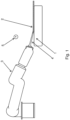
- a system 20 of the present invention is illustrated in Fig. 1 .
- Fig. 1 illustrates a system 20 of the present invention.
- the system 20 comprises a flexible support 1 having a rough surface for placing the casing 2 to be transported.
- the system 20 comprises an actuated arm 3 movable in 3D, and equipped with a finger 4 fitting the interior of the casing 2.
- One or more actuatable rollers can be arranged in such a manner that they can be brought into contact with the finger 4 for shirring the casing 2 onto the finger 4 when the finger has engaged with the casing 2.
- the one or more rollers may be configured to hold a portion of the casing 2 by pressing the rollers against the outer face of a part of the casing 2 mounted on the finger 4 and held between the rollers.
- the system 20 comprises a camera 5.
- the camera 5 is in communication with a control unit (not shown) that receives image information (e.g. a video sequence) from the camera 5.
- the control unit is programmed to direct the finger 4 to the casing 2 when placed on the support 1.
- control unit is further configured to subsequently move the finger 4 with the casing 2 into a position, in which the casing is in contact with the one or more rollers and activate the one or more rollers to shirr the casing 2 onto the finger 4, before moving the finger 4 with the casing 2 e.g. to a device for measuring the diameter thereof, and finally deshirring the casing 2 to transfer it e.g. to a device for measuring the diameter thereof.
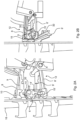
- Fig. 2A illustrates a side view of a clamping device 12 of the system according to the invention.
- the clamping device 12 is configured to be partly inserted into the interior of a casing and partly clamp against the outside of the casing.
- the clamping device 12 is configured to collect a casing that has been received by a receiving structure 6.
- the receiving structure 6 can in one embodiment be detachably attached to a holding device 16.
- the clamping device 12 comprises a pair of engagement structure 14, 14' arranged and configured be inserted into the interior of a casing that has been received by a receiving structure 6.
- the clamping device 12 comprises a pair of intermediate structures 10, 10' arranged and configured to engage with and thus press against the outside of a casing and hereby clamp against the casing 2 when the engagement structure 14, 14' has been inserted into the interior of the casing.
- the first intermediate structure 10 is arranged to press against the outside of a casing from a first direction.
- the second intermediate structure 10' is arranged to press against the outside of a casing from a second direction (preferably the opposite direction).
- the clamping device 12 comprises a pair of arms 8, 8' rotatably arranged with respect to rotational axes X, X'.
- the first engagement structure 14 is provided in the distal end of the first arm 8.
- the second engagement structure 14' is provided in the distal end of the second arm 8'.
- the clamping device 12 comprises another pair of arms 9, 9' rotatably arranged with respect to rotational axes X, X'.
- the first intermediate structure 10 is provided in the distal end of the first arm 9.
- the second intermediate structure 10' is provided in the distal end of the second arm 9'.
- the receiving structures 6, 6' have a cross-shaped cross section.
- a flange portion is provided at the end of the longest leg (plate) of the receiving structures 6, 6'.
- Fig. 2B illustrates another view of the clamping device 12 shown in Fig. 2A .
- the clamping device 12 has been activated and the engagement structures 14, 14' have been brought into engagement with the receiving structure 6.
- a protruding structure protrudes 32 from a central portion of the receiving structure 6.
- the protruding structure protrudes 32 is configured to stop a casing from being moved further along the length of the receiving structure 6.
- the protruding structure protrudes 32 functions a mechanical stop element that prevents the casing from being moved further along the length of the receiving structure 6 once the casing is brought into contact with the protruding structure protrudes 32.
- Fig. 2B the clamping device 12 is being brought into engagement with the receiving structure 6. Since the casing is held in a position, in which there is space between adjacent plates of the receiving structure 6 (see Fig. 16 F for a further explanation), the receiving structure 6 can be inserted into the interior of a casing by sliding the engagement structure 14, 14' along the length of the receiving structure 6. A second receiving structure 6' is placed below the first receiving structure 6. Both the first receiving structure 6 and the second receiving structure 6' are provided with a protruding structure protrudes 32 configured to stop a casing from being moved further along the length of the receiving structure 6, 6'.
- Fig. 3A illustrates a side view of a holding device 16 of the system according to the invention.
- Fig. 3B illustrates a front view of the holding device shown in Fig. 3A .
- the holding device 16 comprises an upright body provided with a plurality of recesses configured to receive a receiving structure 6, 6'.
- a corresponding L-shaped pull structure 18, 18' is arranged.
- Each pull structure 18, 18' comprises a sort distal portion that extends basically perpendicular to the remaining proximal portion of the pull structure 18, 18'.
- the distal portion of each of the pull structure 18, 18' is configured to be partly inserted in to opening of the casing arranged on the receiving structure 6, 6'.
- the pull structures 18, 18' will pull the casing. Accordingly, space is created between a receiving structure 6, 6' and the casing surrounding it. Accordingly, a structure can be inserted in to the space between the casing and the receiving structure.
- the holding device 16 may be used to receive receiving structures 6, 6' being manually attached to the holding device 16. It is possibly to automatically pick up a casing by using a finger and automatically attach the finger or a structure attached thereto to the holding device 16.
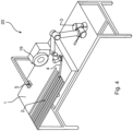
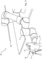
- Fig. 4 illustrates a perspective view of a system 20 according to the invention.
- the system 20 comprises a support 1.
- the support is arranged on a table, however, it may be arranged differently.
- a plurality of casings 2 are placed on the top of the support 1.
- the system 20 comprises a robot arm 3 comprising three segments.
- the distal segment is provided with a finger 4 protruding therefrom.
- the finger is configured to be inserted into the interior of a casing 2.
- the system comprises a roller 19 provided with a centrally arranged recess extending along the entire periphery of the roller 19.
- the robot arm 3 is arranged and configured to transport the finger into a position in which the casing attached to the finger can be brought into contact with the roller 19.
- the system 20 comprises a motor (not shown) configured to drive the roller 19.
- the system 20 moreover comprises a control unit (not shown) configured to activate the motor and hereby rotate the roller 19.
- the system 20 comprises a camera 5 mounted on an arm.
- the camera is arranged and configured to provide visual information that can be used to control the motion of the robot arm 3 and the finger 4.
- the support 1 is flexible and provides a friction sufficient to prevent the lower portion of a casing 2 placed on the support 1 and being in contact with the support 1 from moving when the finger 4 presses against the topside of the casing 4 and is moved along the length of the casing. In order to make this happen, it may be an advantage to ensure that the angle between the finger 4 and the support is smaller than a predefined level. In one embodiment, the angle between the finger 4 and the support is smaller than 30 degrees. In one embodiment, the angle between the finger 4 and the support is smaller than 20 degrees. In one embodiment, the angle between the finger 4 and the support is smaller than 15 degrees. In one embodiment, the angle between the finger 4 and the support is equal to or smaller than 10 degrees.
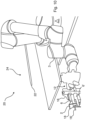
- Fig. 5 illustrates a view of a system according to the invention in a first configuration.
- the system comprises a robot arm 3 and a finger 4 attached to the distal portion of the robot arm 3.
- the finger is configured to pick up a casing 2 placed on a flexible support 1.
- the finger is shaped as an elongated rod having a conical and rounded distal end. Accordingly, the finger 4 will not damage the casing 2 upon picking-up the casing 2. In Fig. 5 the finger is not in contact with the casing 2 yet.
- Fig. 6 illustrates a view of the system shown in Fig. 5 in a second configuration, in which the finger 4 has been moved into a position in which the finger 4 is in contact with the casing 2.
- Fig. 7 illustrates a view of the system shown in Fig. 5 in a third configuration, in which the finger 4 has been moved along the length of the casing 2. It can be seen that the casing 2 surrounds the distal portion of the finger 4.
- Fig. 8 illustrates a view of the system shown in Fig. 5 in a fourth configuration, in which the finger has picked-up the casing 2 and is being lifted in order to transport the casing to a second position.
- Fig. 9 illustrates a view of a system 20 according to the invention in a first configuration.
- the system 20 comprises a robot arm 3 provided with a finger 4 as explained with reference to Fig. 1 , Fig. 4 and Fig. 5 .
- the system 20 also comprises a clamping 12 like the on explained with reference to Fig. 2A and Fig. 2B .
- the system 20 furthermore comprises a holding device 16 as the one explained with reference to Fig. 2A, Fig. 2B , Fig. 3A and Fig. 3B .
- a casing 2 is arranged on a receiving structure 6 that is attached to the holding device 16.
- the casing 2 is pulled by a pull structure 18.
- the gripping device 12 is capable of inserting a structure into the interior of the casing 2 and further expand the casing 2 and hereafter moving it from the receiving structure 6.
- the system 20 comprises a device 24 configured to measure the diameter of casings 2.
- This device 24 comprises a receiving structure 22.
- the receiving structure 22 is shaped as a pipe.
- Fig. 10 illustrates a view of the system 20 shown in Fig. 9 in a second configuration, in which the robot arm 3 has moved the gripping device 12 closer to the casing 2.
- Fig. 11 illustrates a view of the system 20 shown in Fig. 9 in a third configuration, in which the gripping device 12 has inserted a structure into the interior of the casing 2 and has expanded the casing 2.
- Fig. 12 illustrates a view of the system 20 shown in Fig. 9 in a fourth configuration, in which the clamping device 12 has taken the casing 2 from the receiving structure 6. Now the clamping device 12 has already moved the casing 2 in a path towards the receiving structure 22 to attach the casing 2 thereto.
- Fig. 13 illustrates a view of the system 20 shown in Fig. 9 in a fifth configuration, in which the casing 2 has been attached to the distal portion of the receiving structure 22. Another casing 2 is being manually attached to the distal portion of the receiving structure 6.
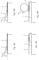
- Fig. 14A illustrates a view of a system according to the invention in a first configuration, in which a finger 4 of the system is placed on the top of a casing 2 arranged on the top of a support 1.
- the finger 4 is being moved along the length of the casing 2.
- the angle ⁇ between the support 1 and the finger 4 is indicated.
- the angle ⁇ may be in the range 5-20 degrees. In one embodiment, the angle ⁇ is in the range 6-15 degrees. Even though not indicated, it may be an advantage to press the finger downwards in order to increase the normal force and thus the friction between the underside of the casing 2 and the support 1.
- Fig. 14B illustrates a view of the system show in Fig. 14A in a second configuration, in which the finger 4 has been moved along the casing 2. It can be seen that the finger 4 now has access to and thus enters the interior of the casing 2.
- Fig. 14C illustrates a view of the system shown in Fig. 14 A in a third configuration, in which the finger 2 is no longer pressing the casing 2 towards the support 1.
- the finger has been raised and angled in such a manner that the finger basically extends parallel to the upper surface of the support 1 and is distanced therefrom. It can be seen that the distal portion of the casing 2 has been picked-up by the finger 4.
- Fig. 14D illustrates a view of the system shown in Fig. 14A in a fourth configuration, in which the finger 4 and the casing 2 attached thereto engages a rotating roller 19. It can be seen that a clockwise rotation of the roller 19 will shirr the casing 2 up on the finger 4.
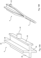
- Fig. 15A illustrates a view of a receiving structure 6 corresponding to the one shown in Fig. 2A, Fig. 2B , Fig. 3A, Fig. 3B and Fig. 9-13 .
- the receiving structure 6 comprises three first plates 26 and a second longer plate 28 fixed to each other to form a body having a cross-shaped cross section.
- a flange 30 is attached to the distal portion of the long plate 28.
- Fig. 15B illustrates a view of another receiving structure 6 according to the invention.
- the receiving structure 6 has a proximal portion shaped as the receiving structure 6 shown in Fig. 16A .
- the distal portion of the receiving structure 6, however, is shaped as a finger 4 as the one explained preciously with reference to Fig. 1 , Fig. 4-8 , Fig. 14A, Fig. 14B, Fig. 14C and Fig 14D .
- Fig. 16A illustrates a casing 2 that has been received by a receiving structure 6 like the one illustrated in Fig. 15A .
- the casing 2 is being pulled by a pull structure 18 and thus sufficient space for entering an engagement structures 14, 14' into the room between the casing 2 and the receiving structure is established.
- the receiving structure 6 comprises a flange 30.
- the casing 2 is in contact with the pull structure 18 and the receiving structure 6.
- Fig. 16B illustrates that the engagement structures 14, 14' expend the casing 2 when being displaced upwards and downwards, respectively (as indicated with the arrows). Therefore, the casing 2 is no longer in contact with the plates 26, 28 of the receiving structure 6. Moreover, the casing 2 is no longer in contact with the pull structure 18.
- the casing 2 can now be moved by sliding the engagement structures 14, 14' being in contact with the inside portion of the casing 2 along the length of the receiving structure 6.
- intermediate structures are arranged in a position, in which they can be used to clamp against the outside surface of the casing 2.
- transportation of the casing 2 can be controlled because the casing 2 is both clamped from the inside (by means of the engagement structures 14, 14') and from the outside by the intermediate structures.
Landscapes
- Life Sciences & Earth Sciences (AREA)
- Engineering & Computer Science (AREA)
- Wood Science & Technology (AREA)
- Zoology (AREA)
- Food Science & Technology (AREA)
- Manipulator (AREA)
- Length Measuring Devices By Optical Means (AREA)
- Electrical Discharge Machining, Electrochemical Machining, And Combined Machining (AREA)
Description
- The present invention relates to a system for the automated picking up and transporting of a casing of indefinite length into relationship with a device for further processing, such as for measuring the diameter or tubing of the casing.
- In slaughterhouses, carcasses are examined and processed based on measurement of individual carcasses. To determine the quality and/or to cut the carcass into valuable parts of meat, the examination and processing devices are controlled relative to the location of anatomical parts of the carcass. Intestines from the animals are processed in a similar way, and e.g. natural casings are of major interest.
- The first phase in the processing of a natural casing involves cleaning the casing immediately after the slaughtering of the animal, to avoid any risk of microbial growth and fermentation. The second phase involves carrying out the scraping of the inner wall of the casing, that is to say removing a so-called mucous layer from it, and the scraping of the outer part of the casing which has a protective membrane, in order to preserve only the muscular central part composed of two planes of smooth white fibres. The third phase involves carrying out the calibration of the casing as a function of its diameter. In fact, a casing varies in diameter and quality over its entire length, these two parameters themselves varying with the age, breed, feeding method and rearing system of the animals. The calibration operation is carried out, in a known way, by inflating the casing with water or air in order to measure its diameter. The fourth phase in the processing of the casing involves packaging the latter according to its size and quality, this packaging in predetermined lengths being carried out in the form of cured, dry or briny hanks or by folding on a support, such as a rigid tube or an elongate support of flexible synthetic material.
- These four successive phases in the processing of the casing are carried out independently of one another and empirically, the quality of the end result being governed essentially by the experience of the particular operator.
-
GB 657183 A - The object of the present invention is to overcome intervention of an operator between the second and third phases by providing a method and a system for carrying out this step. Another object of the present invention is to reduce costs associated with this process by providing a method and system for automated handling of the casings. It is an object of the invention to provide an improved apparatus that is capable of picking up the casing from the support in an automatic and controlled manner.
- The object of the present invention can be achieved by a system as defined in
claim 1 and by a method as defined inclaim 10. Preferred embodiments are defined in the dependent subclaims, explained in the following description and illustrated in the accompanying drawings. - The system according to the invention is a system for use in picking up and transporting a casing of indefinite length into relationship with a device, such as a device for measuring the diameter or tubing of the casing, said system comprising:
- a support for placing the casing to be picked up,
- a camera for detecting the casing when placed on the support, wherein the system comprises:
- an actuated arm, such as a robot arm, equipped with a finger fitting the interior of the casing and
- a control unit receiving image information from the camera, wherein the control unit is configured to direct the finger to the casing when placed on the support, and subsequently move the finger with the casing to a device, such as a device for measuring the diameter thereof, and finally deshirring the casing to transfer it to such device.
- Hereby, it is possible to provide a system for improved automated handling of casings.
- In one embodiment, the system comprises a device for measuring the diameter or tubing of the casing.
- In one embodiment, the support for placing the casing to be picked up comprises or is made in a flexible material.
- In one embodiment, at least a portion of the support is made of a foam material.
- The camera for detecting the casing when placed on the support may be of any suitable type. The camera may be connected to the control unit by either a wired or a wireless connection.
- In one embodiment, the actuated arm is a robot arm.
- The actuated arm is equipped with a finger fitting the interior of the casing. In one embodiment, the finger is rod-shaped.
- The control unit is configured to receive image information from the camera. The image information may be one or more images. In one embodiment, the image information is a video sequence.
- The control unit is configured to direct the finger to the casing when the casing is placed on the support. Accordingly, in a preferred embodiment the diameter or width of the finger is smaller than or equal to the width or diameter of the casing to be picked up (while the casing is placed on the support).
- The control unit is configured to initiate that the finger is move together with the casing to a device, such as a device for measuring the diameter thereof. By the term "to a device" is meant to a position, from which the device is capable of handling the casing, e.g. initiate and carry out a process with the purpose of measuring the diameter of the casing.
- In one embodiment, the control unit is configured to activate one or more mechanisms configured to deshirr the casing in order to allow the casing to be transferred to a device. The system preferably comprises a motor (e.g. an AC motor or a DC motor) arranged and configured to activated by the control unit. In one embodiment, the motor is configured to rotate one or more rollers.
- The system according to the invention comprises one or more actuatable rollers configured to be brought into engagement with the finger in order to shirr the casing onto the finger (when the finger has engaged with the casing).
- The control unit is configured to activate the one or more rollers to shirr the casing onto the finger. This may be done by controlling (including turning on, turning off or regulating the speed of a motor arranged and configured to drive the one or more rollers.
- In one embodiment, the system comprises two rollers configured to hold a portion of the casing by pressing the rollers against the outer face of a part of the casing mounted on the finger and held between the rollers.
- It may be advantageous that the support has a surface configured to prevent the casing from sliding away from the support when the finger interacts with the casing. Furthermore, it may be beneficial that the support is made from a flexible material having a rough surface, preventing the casing from sliding away from the finger, and allowing the finger to move in between the two layers of the casing laying on the support. Hereby, the finger is allowed to displace an upper portion of the casing relative to a lower portion of the casing in order to let the finger enter the interior of the casing while the bottom portion of the casing remains in a fixed portion relative to the portion of the support at which portion the casing is placed (the casing may, however, be moved downwards together with the support if the support is resilient and is compressed due to the pressure provided towards it by the finger). By the term "rough surface" is meant any surface providing a coefficient of friction large enough (even when the casing is wet) to prevent the casing from sliding away from the finger, and allowing the finger to move in between the two layers of the casing laying on the support.
- In one embodiment, the support is coated with a fabric. This may be advantageous because the coated fabric may have a desirable coefficient of friction.
- It may be beneficial that the one or more rollers are provided in a separate device or mounted on the actuated arm so as to be movable onto the outer surface of the casing, when the finger has engaged with the casing, wherein the one or more rollers when activated are configured to ensure that the entire casing is shirred onto the finger.
- Hereby, it is possible to provide a modular system comprising separate modules that can be replaced or serviced independently. Moreover, the system can be more user-friendly because the type of device can be selected by the user.
- It may be an advantage that the support is dark so as to provide optimal background contrast relative to the casing.
- In one embodiment, the support is made from or covered with a light reflecting material. Hereby, it is possible to provide highly useful image data.
- It may be advantageous that the system comprises an infrared irradiating device configured to illuminate the support.
- It may be beneficial that the one or more rollers are conical.
- In one embodiment, the system comprises a receiving structure configured to inserted into the interior of the casing hereby creating a plurality of spaces between the outside surface of the receiving structure and the inside of the casing, wherein the system comprise a plurality of moveably arranged engagement structures configured to be inserted into said spaces, wherein the engagement structures are configured to be moved in order to expand the casing hereby bringing the (inside surface of the) casing into contact with the engagement structures and removing the contact between the casing and one or more portions of the receiving structure so that the casing can be moved by moving the engagement structures.
- In one embodiment, the engagement structures are configured to be moved perpendicular to the length of the receiving structure and hereby expand the casing.
- In one embodiment, the engagement structures are configured to be moved along the length of the receiving structure when the casing is attached to the engagement structures. Hereby, it is possible to move the casing away from the receiving structure e.g. to place the casing on another machine structure (e.g. in order to measure the diameter of the casing).
- In one embodiment, the system comprises intermediate structures (like the one illustrated in
Fig. 2A and Fig 2B ) arranged in a position, in which they can be used to clamp against the outside surface of a casing received by a receiving structure. Hereby, it is possible to better control transportation of the casing (since the casing is clamped both from the inside by means of the engagement structures and from the outside by the intermediate structures). - The method according to the invention is a method for picking and transporting a casing of indefinite length into relationship with a device, such as a device for measuring the diameter of the casing, wherein the method comprises the steps:
- placing the casing on a flexible support with a rough surface, wherein the process comprises the step of:
- directing an actuated arm, such as a robot arm, equipped with a finger fitting the interior of the casing towards the casing, whereby the finger engages with the casing and
- moving the finger with the casing to a device, such as a device for measuring the diameter thereof.
- Hereby, it is possible to provide an improved method for automated handling of casings.
- The method according to the invention comprises the step of activating one or more actuated rollers to shirr the casing onto the finger. Hereby, it is possible to ensure that the entire casing is picked up.
- It may be advantageous that the one or more rollers are provided in a separate device or mounted on the actuator so as to be movable onto the outer surface of the casing, when the finger has engaged with the casing, wherein the one or more rollers when activated are configured to ensure that the entire casing is shirred onto the finger.
- The present invention provides solutions to ensure that a casing can be transported after it has been cleaned to a site, where its diameter can be measured.
- The support may be coated with a fabric and may be made of a spongy material so as to allow the picking of the finger without the finger damaging the casing with holes. In an embodiment, the support is in a dark colour so as to give optimal background contrast relative to the casing. Alternatively, the support is made from or covered with a light reflecting material, which is suitable for being irradiated with an infrared irradiating device, which will also provide a good contrast between the casing and the support so as to enable the camera to localize the position of the casing.
- The rollers may be provided in a separate device or mounted on the actuated arm so as to be movable onto the outer surface of the casing, when the finger is engaged with the casing, said rollers is when activated ensuring that the entire casing is shirred onto the finger.
- Preferably, the rollers are conical in shape.
- In one embodiment, the method comprises the step of applying a receiving structure configured to inserted into the interior of the casing hereby creating a plurality of spaces between the outside surface of the receiving structure and the inside of the casing, wherein the method comprises the step of applying a plurality of moveably arranged engagement structures configured to be inserted into said spaces, wherein the engagement structures are configured to be moved in order to expand the casing hereby bringing the casing into contact with the engagement structures and removing the contact between the casing and one or more portions of the receiving structure so that the casing can be moved by moving the engagement structures.
- In one embodiment, not according to the invention, the engagement structures are configured to be moved perpendicular to the length of the receiving structure and hereby expand the casing.
- In one embodiment, not according to the invention, the engagement structures are configured to be moved along the length of the receiving structure when the casing is attached to the engagement structures. Hereby, it is possible to move the casing away from the receiving structure e.g. to place the casing on another machine structure (e.g. in order to measure the diameter of the casing).
- The invention will become more fully understood from the detailed description given herein below. The accompanying drawings are given by way of illustration only, and thus, they are not limitative of the present invention. In the accompanying drawings:
- Fig. 1
- shows a side view of the system of the present invention;
- Fig. 2A
- shows a view of a clamping device of the system according to the invention;
- Fig. 2B
- shows another view of the clamping device shown in
Fig. 2A ; - Fig. 3A
- shows a side view of a holding device of the system according to the invention;
- Fig. 3B
- shows another view of the holding device shown in
Fig. 3A ; - Fig. 4
- shows a perspective view of a system according to the invention;
- Fig. 5
- shows a view of a system according to the invention in a first configuration;
- Fig. 6
- shows a view of the system shown in
Fig. 5 in a second configuration; - Fig. 7
- shows a view of the system shown in
Fig. 5 in a third configuration; - Fig. 8
- shows a view of the system shown in
Fig. 5 in a fourth configuration; - Fig. 9
- shows a view of a system according to the invention in a first configuration;
- Fig. 10
- shows a view of the system shown in
Fig. 9 in a second configuration; - Fig. 11
- shows a view of the system shown in
Fig. 9 in a third configuration; - Fig. 12
- shows a view of the system shown in
Fig. 9 in a fourth configuration; - Fig. 13
- shows a view of the system shown in
Fig. 9 in a fifth configuration; - Fig. 14A
- shows a view of a system according to the invention in a first configuration;
- Fig. 14B
- shows a view of a system show in
Fig. 14A in a second configuration; - Fig. 14C
- shows a view of a system show in
Fig. 14A in a third configuration; - Fig. 14D
- shows a view of a system show in
Fig. 14A in a fourth configuration; - Fig. 15A
- shows a view of a receiving structure according to the invention;
- Fig. 15B
- shows a view of another receiving structure according to the invention;
- Fig. 16A
- shows a casing received by a receiving structure and
- Fig. 16B
- shows that the engagement structures can expend the casing.
- Referring now in detail to the drawings for the purpose of illustrating preferred embodiments of the present invention, a
system 20 of the present invention is illustrated inFig. 1 . -
Fig. 1 illustrates asystem 20 of the present invention. Thesystem 20 comprises aflexible support 1 having a rough surface for placing thecasing 2 to be transported. Thesystem 20 comprises an actuatedarm 3 movable in 3D, and equipped with afinger 4 fitting the interior of thecasing 2. One or more actuatable rollers (not shown) can be arranged in such a manner that they can be brought into contact with thefinger 4 for shirring thecasing 2 onto thefinger 4 when the finger has engaged with thecasing 2. The one or more rollers may be configured to hold a portion of thecasing 2 by pressing the rollers against the outer face of a part of thecasing 2 mounted on thefinger 4 and held between the rollers. - The
system 20 comprises acamera 5. In order to detect the position of thecasing 2 on thesupport 1 thecamera 5 is used. Thecamera 5 is in communication with a control unit (not shown) that receives image information (e.g. a video sequence) from thecamera 5. The control unit is programmed to direct thefinger 4 to thecasing 2 when placed on thesupport 1. - In one embodiment, the control unit is further configured to subsequently move the
finger 4 with thecasing 2 into a position, in which the casing is in contact with the one or more rollers and activate the one or more rollers to shirr thecasing 2 onto thefinger 4, before moving thefinger 4 with thecasing 2 e.g. to a device for measuring the diameter thereof, and finally deshirring thecasing 2 to transfer it e.g. to a device for measuring the diameter thereof. -
Fig. 2A illustrates a side view of aclamping device 12 of the system according to the invention. The clampingdevice 12 is configured to be partly inserted into the interior of a casing and partly clamp against the outside of the casing. - The clamping
device 12 is configured to collect a casing that has been received by a receivingstructure 6. The receivingstructure 6 can in one embodiment be detachably attached to a holdingdevice 16. The clampingdevice 12 comprises a pair ofengagement structure 14, 14' arranged and configured be inserted into the interior of a casing that has been received by a receivingstructure 6. - The clamping
device 12 comprises a pair ofintermediate structures 10, 10' arranged and configured to engage with and thus press against the outside of a casing and hereby clamp against thecasing 2 when theengagement structure 14, 14' has been inserted into the interior of the casing. - The first
intermediate structure 10 is arranged to press against the outside of a casing from a first direction. Likewise, the second intermediate structure 10' is arranged to press against the outside of a casing from a second direction (preferably the opposite direction). - The clamping
device 12 comprises a pair ofarms 8, 8' rotatably arranged with respect to rotational axes X, X'. Thefirst engagement structure 14 is provided in the distal end of thefirst arm 8. The second engagement structure 14' is provided in the distal end of the second arm 8'. - The clamping
device 12 comprises another pair ofarms 9, 9' rotatably arranged with respect to rotational axes X, X'. The firstintermediate structure 10 is provided in the distal end of thefirst arm 9. The second intermediate structure 10' is provided in the distal end of the second arm 9'. - The receiving
structures 6, 6' have a cross-shaped cross section. A flange portion is provided at the end of the longest leg (plate) of the receivingstructures 6, 6'. -
Fig. 2B illustrates another view of theclamping device 12 shown inFig. 2A . The clampingdevice 12 has been activated and theengagement structures 14, 14' have been brought into engagement with the receivingstructure 6. A protruding structure protrudes 32 from a central portion of the receivingstructure 6. The protruding structure protrudes 32 is configured to stop a casing from being moved further along the length of the receivingstructure 6. The protruding structure protrudes 32 functions a mechanical stop element that prevents the casing from being moved further along the length of the receivingstructure 6 once the casing is brought into contact with the protruding structure protrudes 32. - In
Fig. 2B theclamping device 12 is being brought into engagement with the receivingstructure 6. Since the casing is held in a position, in which there is space between adjacent plates of the receiving structure 6 (see Fig. 16 F for a further explanation), the receivingstructure 6 can be inserted into the interior of a casing by sliding theengagement structure 14, 14' along the length of the receivingstructure 6. A second receiving structure 6' is placed below thefirst receiving structure 6. Both thefirst receiving structure 6 and the second receiving structure 6' are provided with a protruding structure protrudes 32 configured to stop a casing from being moved further along the length of the receivingstructure 6, 6'. -
Fig. 3A illustrates a side view of a holdingdevice 16 of the system according to the invention.Fig. 3B illustrates a front view of the holding device shown inFig. 3A . The holdingdevice 16 comprises an upright body provided with a plurality of recesses configured to receive a receivingstructure 6, 6'. Next to each recess, a corresponding L-shapedpull structure pull structure pull structure pull structure structure 6, 6'. Hereby, thepull structures structure 6, 6' and the casing surrounding it. Accordingly, a structure can be inserted in to the space between the casing and the receiving structure. - The holding
device 16 may be used to receive receivingstructures 6, 6' being manually attached to the holdingdevice 16. It is possibly to automatically pick up a casing by using a finger and automatically attach the finger or a structure attached thereto to the holdingdevice 16. -
Fig. 4 illustrates a perspective view of asystem 20 according to the invention. Thesystem 20 comprises asupport 1. The support is arranged on a table, however, it may be arranged differently. A plurality ofcasings 2 are placed on the top of thesupport 1. Thesystem 20 comprises arobot arm 3 comprising three segments. The distal segment is provided with afinger 4 protruding therefrom. The finger is configured to be inserted into the interior of acasing 2. - The system comprises a
roller 19 provided with a centrally arranged recess extending along the entire periphery of theroller 19. Therobot arm 3 is arranged and configured to transport the finger into a position in which the casing attached to the finger can be brought into contact with theroller 19. Thesystem 20 comprises a motor (not shown) configured to drive theroller 19. Thesystem 20 moreover comprises a control unit (not shown) configured to activate the motor and hereby rotate theroller 19. - The
system 20 comprises acamera 5 mounted on an arm. The camera is arranged and configured to provide visual information that can be used to control the motion of therobot arm 3 and thefinger 4. - The
support 1 is flexible and provides a friction sufficient to prevent the lower portion of acasing 2 placed on thesupport 1 and being in contact with thesupport 1 from moving when thefinger 4 presses against the topside of thecasing 4 and is moved along the length of the casing. In order to make this happen, it may be an advantage to ensure that the angle between thefinger 4 and the support is smaller than a predefined level. In one embodiment, the angle between thefinger 4 and the support is smaller than 30 degrees. In one embodiment, the angle between thefinger 4 and the support is smaller than 20 degrees. In one embodiment, the angle between thefinger 4 and the support is smaller than 15 degrees. In one embodiment, the angle between thefinger 4 and the support is equal to or smaller than 10 degrees. -
Fig. 5 illustrates a view of a system according to the invention in a first configuration. The system comprises arobot arm 3 and afinger 4 attached to the distal portion of therobot arm 3. - The finger is configured to pick up a
casing 2 placed on aflexible support 1. The finger is shaped as an elongated rod having a conical and rounded distal end. Accordingly, thefinger 4 will not damage thecasing 2 upon picking-up thecasing 2. InFig. 5 the finger is not in contact with thecasing 2 yet. -
Fig. 6 illustrates a view of the system shown inFig. 5 in a second configuration, in which thefinger 4 has been moved into a position in which thefinger 4 is in contact with thecasing 2. -
Fig. 7 illustrates a view of the system shown inFig. 5 in a third configuration, in which thefinger 4 has been moved along the length of thecasing 2. It can be seen that thecasing 2 surrounds the distal portion of thefinger 4. -
Fig. 8 illustrates a view of the system shown inFig. 5 in a fourth configuration, in which the finger has picked-up thecasing 2 and is being lifted in order to transport the casing to a second position. -
Fig. 9 illustrates a view of asystem 20 according to the invention in a first configuration. Thesystem 20 comprises arobot arm 3 provided with afinger 4 as explained with reference toFig. 1 ,Fig. 4 andFig. 5 . - The
system 20 also comprises a clamping 12 like the on explained with reference toFig. 2A and Fig. 2B . Thesystem 20 furthermore comprises a holdingdevice 16 as the one explained with reference toFig. 2A, Fig. 2B ,Fig. 3A and Fig. 3B . Acasing 2 is arranged on a receivingstructure 6 that is attached to the holdingdevice 16. Thecasing 2 is pulled by apull structure 18. Accordingly, the grippingdevice 12 is capable of inserting a structure into the interior of thecasing 2 and further expand thecasing 2 and hereafter moving it from the receivingstructure 6. - The
system 20 comprises adevice 24 configured to measure the diameter ofcasings 2. Thisdevice 24 comprises a receivingstructure 22. In one embodiment, the receivingstructure 22 is shaped as a pipe. -
Fig. 10 illustrates a view of thesystem 20 shown inFig. 9 in a second configuration, in which therobot arm 3 has moved thegripping device 12 closer to thecasing 2. -
Fig. 11 illustrates a view of thesystem 20 shown inFig. 9 in a third configuration, in which thegripping device 12 has inserted a structure into the interior of thecasing 2 and has expanded thecasing 2. -
Fig. 12 illustrates a view of thesystem 20 shown inFig. 9 in a fourth configuration, in which theclamping device 12 has taken thecasing 2 from the receivingstructure 6. Now theclamping device 12 has already moved thecasing 2 in a path towards the receivingstructure 22 to attach thecasing 2 thereto. -
Fig. 13 illustrates a view of thesystem 20 shown inFig. 9 in a fifth configuration, in which thecasing 2 has been attached to the distal portion of the receivingstructure 22. Anothercasing 2 is being manually attached to the distal portion of the receivingstructure 6. -
Fig. 14A illustrates a view of a system according to the invention in a first configuration, in which afinger 4 of the system is placed on the top of acasing 2 arranged on the top of asupport 1. Thefinger 4 is being moved along the length of thecasing 2. The angle α between thesupport 1 and thefinger 4 is indicated. The angle α may be in the range 5-20 degrees. In one embodiment, the angle α is in the range 6-15 degrees. Even though not indicated, it may be an advantage to press the finger downwards in order to increase the normal force and thus the friction between the underside of thecasing 2 and thesupport 1. -
Fig. 14B illustrates a view of the system show inFig. 14A in a second configuration, in which thefinger 4 has been moved along thecasing 2. It can be seen that thefinger 4 now has access to and thus enters the interior of thecasing 2. -
Fig. 14C illustrates a view of the system shown inFig. 14 A in a third configuration, in which thefinger 2 is no longer pressing thecasing 2 towards thesupport 1. The finger has been raised and angled in such a manner that the finger basically extends parallel to the upper surface of thesupport 1 and is distanced therefrom. It can be seen that the distal portion of thecasing 2 has been picked-up by thefinger 4. -
Fig. 14D illustrates a view of the system shown inFig. 14A in a fourth configuration, in which thefinger 4 and thecasing 2 attached thereto engages arotating roller 19. It can be seen that a clockwise rotation of theroller 19 will shirr thecasing 2 up on thefinger 4. -
Fig. 15A illustrates a view of a receivingstructure 6 corresponding to the one shown inFig. 2A, Fig. 2B ,Fig. 3A, Fig. 3B andFig. 9-13 . The receivingstructure 6 comprises threefirst plates 26 and a secondlonger plate 28 fixed to each other to form a body having a cross-shaped cross section. Aflange 30 is attached to the distal portion of thelong plate 28. -
Fig. 15B illustrates a view of another receivingstructure 6 according to the invention. The receivingstructure 6 has a proximal portion shaped as the receivingstructure 6 shown inFig. 16A . The distal portion of the receivingstructure 6, however, is shaped as afinger 4 as the one explained preciously with reference toFig. 1 ,Fig. 4-8 ,Fig. 14A, Fig. 14B, Fig. 14C and Fig 14D . -
Fig. 16A illustrates acasing 2 that has been received by a receivingstructure 6 like the one illustrated inFig. 15A . Thecasing 2 is being pulled by apull structure 18 and thus sufficient space for entering anengagement structures 14, 14' into the room between thecasing 2 and the receiving structure is established. It can be seen the receivingstructure 6 comprises aflange 30. Thecasing 2 is in contact with thepull structure 18 and the receivingstructure 6. -
Fig. 16B illustrates that theengagement structures 14, 14' expend thecasing 2 when being displaced upwards and downwards, respectively (as indicated with the arrows). Therefore, thecasing 2 is no longer in contact with theplates structure 6. Moreover, thecasing 2 is no longer in contact with thepull structure 18. - Accordingly, the
casing 2 can now be moved by sliding theengagement structures 14, 14' being in contact with the inside portion of thecasing 2 along the length of the receivingstructure 6. - It may be an advantage, that intermediate structures (like the one illustrated in
Fig. 2A and Fig 2B ) are arranged in a position, in which they can be used to clamp against the outside surface of thecasing 2. Hereby, transportation of thecasing 2 can be controlled because thecasing 2 is both clamped from the inside (by means of theengagement structures 14, 14') and from the outside by the intermediate structures. -
- 1
- Support
- 2
- Casing
- 3
- Actuated arm
- 4
- Finger
- 5
- Camera
- 6, 6', 6"
- Receiving structure
- 8, 8'
- Arm
- 9, 9'
- Arm
- 10, 10'
- Intermediate structure
- 12
- Clamping device
- 14, 14'
- Engagement structure
- 16
- Holding device
- 18, 18'
- Pull structure
- 19
- Roller
- 20
- System
- 22
- Receiving structure
- 24
- Device
- 26
- Plate
- 28
- Plate
- 30
- Flange
- 32
- Protruding structure
- X, X'
- Axis of rotation
Claims (12)
- A system (20) for use in picking up and transporting a casing (2) of indefinite length into relationship with a device (24), such as a device for measuring the diameter or tubing of the casing (2), said system (20) comprising:- a support (1) for placing the casing (2) to be picked up,- a camera (5) for detecting the casing (2) when placed on the support (1),the system (20) comprises:- an actuated arm (3), such as a robot arm, equipped with a finger (4) fitting the interior of the casing (2) and- a control unit receiving image information from the camera (5), wherein the control unit is configured to direct the finger (4) to the casing (2) when placed on the support (1), and subsequently move the finger (4) with the casing (2) to a device, such as a device for measuring the diameter thereof, and finally deshirring the casing (2) to transfer it to such devicewherein the system (20) further comprises:- one or more actuatable rollers (18) configured to be brought into engagement with the finger (4) for shirring the casing (2) onto the finger (4) when the finger (4) has engaged with the casing (2), wherein the control unit is configured to activate the one or more rollers (18) to shirr the casing (2) onto the finger (4).
- A system (20) according to claim 1, wherein the support (1) has a surface configured to prevent the casing (2) from sliding away from the support (1) when the finger (4) interacts with the casing (2), wherein the support (1) is made from a flexible material having a rough surface, preventing the casing (2) from sliding away from the finger (4), and allowing the finger (4) to move in between the two layers of the casing (2) laying on the support (1).
- A system (20) according to one of the preceding claims, wherein the support (1) is coated with a fabric.
- A system (20) according to one of the preceding claims, wherein the one or more rollers (18) are provided in a separate device or mounted on the actuated arm (3) so as to be movable onto the outer surface of the casing (2), when the finger (4) has engaged with the casing (2), wherein the one or more rollers (18) when activated are configured to ensure that the entire casing (2) is shirred onto the finger (4).
- A system (20) according to one of the preceding claims, wherein the support (1) is dark so as to provide optimal background contrast relative to the casing (2).
- A system (20) according to one of the preceding claims, wherein the support (1) is made from or covered with a light reflecting material.
- A system (20) according to one of the preceding claims , wherein the system (20) comprises an infrared irradiating device configured to illuminate the support (1).
- A system (20) according to one of the preceding claims , wherein the one or more rollers (18) are conical.
- A system (20) according to one of the preceding claims, wherein the system (20) comprises several intermediate structures (10, 10') arranged in a position, in which the intermediate structures (10, 10') can be used to clamp against the outside surface of a casing (2) received by a receiving structure (6).
- A method for picking and transporting a casing (2) of indefinite length into relationship with a device, such as a device for measuring the diameter of the casing (2), wherein the method comprises the steps:- placing the casing (2) on a flexible support (1) with a rough surface, characterised in that the process comprises the step of:- directing an actuated arm (3), such as a robot arm, equipped with a finger (4) fitting the interior of the casing (2) towards the casing (2), whereby the finger (4) engages with the casing (2) and- moving the finger (4) with the casing (2) to a device, such as a device for measuring the diameter thereof.wherein the method further comprises the step of activating one or more actuated rollers (18) to shirr the casing (2) onto the finger (4).
- A method according to claim 10 , wherein the one or more rollers (18) are provided in a separate device or mounted on the actuator so as to be movable onto the outer surface of the casing (2), when the finger (4) has engaged with the casing (2), wherein the one or more rollers (18) when activated are configured to ensure that the entire casing (2) is shirred onto the finger (1).
- A method according to one of the preceding claims 10-11, wherein the method comprises the step of applying a receiving structure (6, 6') configured to be inserted into the interior of the casing (2) hereby creating a plurality of spaces between the outside surface of the receiving structure (6, 6') and the inside of the casing (2), wherein the method comprises the step of applying a plurality of moveably arranged engagement structures (14, 14') configured to be inserted into said spaces, wherein the engagement structures (14, 14') are configured to be moved in order to expand the casing (2) hereby bringing the casing (2) into contact with the engagement structures (14, 14') and removing the contact between the casing (2) and one or more portions of the receiving structure (6, 6') so that the casing (2) can be moved by moving the engagement structures (14, 14').
Applications Claiming Priority (2)
| Application Number | Priority Date | Filing Date | Title |
|---|---|---|---|
| DKPA201870828A DK180200B1 (en) | 2018-12-19 | 2018-12-19 | System and Process for Picking and Transporting a Casing |
| PCT/DK2019/050395 WO2020125892A1 (en) | 2018-12-19 | 2019-12-16 | System and process for picking up and transporting a casing |
Publications (3)
| Publication Number | Publication Date |
|---|---|
| EP3897164A1 EP3897164A1 (en) | 2021-10-27 |
| EP3897164C0 EP3897164C0 (en) | 2023-06-07 |
| EP3897164B1 true EP3897164B1 (en) | 2023-06-07 |
Family
ID=69143366
Family Applications (1)
| Application Number | Title | Priority Date | Filing Date |
|---|---|---|---|
| EP19832545.8A Active EP3897164B1 (en) | 2018-12-19 | 2019-12-16 | System and process for picking up and transporting a casing |
Country Status (6)
| Country | Link |
|---|---|
| US (1) | US11716999B2 (en) |
| EP (1) | EP3897164B1 (en) |
| DK (1) | DK180200B1 (en) |
| ES (1) | ES2954374T3 (en) |
| PL (1) | PL3897164T3 (en) |
| WO (1) | WO2020125892A1 (en) |
Families Citing this family (3)
| Publication number | Priority date | Publication date | Assignee | Title |
|---|---|---|---|---|
| DK180658B1 (en) | 2020-09-24 | 2021-11-11 | Proxima Centauri Aps | Flow control system and method for controlling the liquid flow |
| DK181131B1 (en) | 2020-09-24 | 2023-02-13 | Proxima Centauri Aps | End Detection Unit |
| EP4275501A1 (en) * | 2022-05-12 | 2023-11-15 | Poly-clip System GmbH & Co. KG | System and method for producing sausage shaped products |
Family Cites Families (11)
| Publication number | Priority date | Publication date | Assignee | Title |
|---|---|---|---|---|
| US2187790A (en) | 1937-09-23 | 1940-01-23 | Packers Machinery Company | Apparatus for measuring intestines |
| GB657183A (en) | 1949-02-07 | 1951-09-12 | Walter David Kennedy | Improvements in or relating to means for feeding collapsible tubular members on to acore |
| LU33675A1 (en) | 1954-07-07 | |||
| DE1432502A1 (en) * | 1964-04-18 | 1969-02-13 | Freudenberg Carl Fa | Device for gathering sausage casings |
| FR2638612B1 (en) | 1988-11-08 | 1992-07-17 | Alpes Boyauderie | METHOD FOR CALIBRATION, MEASUREMENT OF LENGTH AND CONDITIONING OF LINES OF PIPES USED IN MEAT PRODUCTS AND DEVICE FOR IMPLEMENTING SAME |
| DE19619713C2 (en) * | 1996-05-15 | 1999-10-21 | Handtmann Albert Maschf | Method and device for applying a sausage casing directly to a filling pipe |
| DE102007012777B4 (en) * | 2007-03-16 | 2010-06-24 | Poly-Clip System Gmbh & Co Kg | Method and device for the controlled closing of at least one clip around a filling material-free plait section between two filling material sections enclosed by a cover |
| EP2305043B2 (en) * | 2009-10-02 | 2020-12-02 | Poly-clip System GmbH & Co. KG | Method and system for weighing products |
| EP2384638B2 (en) * | 2010-05-04 | 2025-04-16 | Poly-clip System GmbH & Co. KG | Method for transporting, removing or inserting longitudinal rod-like elements and handling system |
| DE102012013031A1 (en) * | 2012-06-29 | 2014-04-24 | Liebherr-Verzahntechnik Gmbh | Device for the automated detection and removal of workpieces |
| DK3558008T3 (en) | 2016-12-21 | 2024-07-22 | Teknologisk Inst | A SYSTEM FOR TREATMENT OF ANIMAL INTESTINES PARTICULARLY IN THE AFTER-TREATMENT PROCESS |
-
2018
- 2018-12-19 DK DKPA201870828A patent/DK180200B1/en active IP Right Grant
-
2019
- 2019-12-16 EP EP19832545.8A patent/EP3897164B1/en active Active
- 2019-12-16 ES ES19832545T patent/ES2954374T3/en active Active
- 2019-12-16 PL PL19832545.8T patent/PL3897164T3/en unknown
- 2019-12-16 WO PCT/DK2019/050395 patent/WO2020125892A1/en not_active Ceased
-
2021
- 2021-06-16 US US17/349,036 patent/US11716999B2/en active Active
Also Published As
| Publication number | Publication date |
|---|---|
| DK201870828A1 (en) | 2020-08-03 |
| US11716999B2 (en) | 2023-08-08 |
| EP3897164A1 (en) | 2021-10-27 |
| DK180200B1 (en) | 2020-08-13 |
| US20210307341A1 (en) | 2021-10-07 |
| ES2954374T3 (en) | 2023-11-21 |
| PL3897164T3 (en) | 2023-12-18 |
| EP3897164C0 (en) | 2023-06-07 |
| WO2020125892A1 (en) | 2020-06-25 |
Similar Documents
| Publication | Publication Date | Title |
|---|---|---|
| US11716999B2 (en) | System and process for picking up and transporting a casing | |
| US9155315B2 (en) | Method and an apparatus for suspending birds from an overhead conveyor | |
| US10362760B2 (en) | Robot and method for milking a cow by this robot | |
| CN108553196B (en) | An automatic device and automatic control method for beak trimming and vaccine injection | |
| EP1222858B1 (en) | Method and device for processing a cluster of organs of a slaughtered animal | |
| CN107668161B (en) | The net thorax robot system of poultry based on machine vision | |
| EP3648582B1 (en) | Transfer machine for laying eggs on a floor of a poultry house, said eggs being located in setter trays in which they were set | |
| KR970000231B1 (en) | Method and device for calibrating, measuring the length and conditioning portion of sausage casings | |
| CN212279692U (en) | Automatic chamber system of drawing of poultry robot | |
| CN109952509A (en) | Egg inspection and repositioning equipment for in ovo injection machines | |
| JP7822377B2 (en) | Apparatus and method for removing leaf lard from slaughtered animals | |
| CN107374647B (en) | Blood drawing test system | |
| US20080233852A1 (en) | Device and Method for Cleaning the Abdominal Cavity in Fish | |
| AU2021250830B2 (en) | A bung driller with a bung holder | |
| WO2000013492A1 (en) | A device for cleaning teat cups used for milking dairy animals | |
| WO2009048412A1 (en) | A milking member and method of preparing it for attachment |
Legal Events
| Date | Code | Title | Description |
|---|---|---|---|
| STAA | Information on the status of an ep patent application or granted ep patent |
Free format text: STATUS: UNKNOWN |
|
| STAA | Information on the status of an ep patent application or granted ep patent |
Free format text: STATUS: THE INTERNATIONAL PUBLICATION HAS BEEN MADE |
|
| PUAI | Public reference made under article 153(3) epc to a published international application that has entered the european phase |
Free format text: ORIGINAL CODE: 0009012 |
|
| STAA | Information on the status of an ep patent application or granted ep patent |
Free format text: STATUS: REQUEST FOR EXAMINATION WAS MADE |
|
| 17P | Request for examination filed |
Effective date: 20210617 |
|
| AK | Designated contracting states |
Kind code of ref document: A1 Designated state(s): AL AT BE BG CH CY CZ DE DK EE ES FI FR GB GR HR HU IE IS IT LI LT LU LV MC MK MT NL NO PL PT RO RS SE SI SK SM TR |
|
| DAV | Request for validation of the european patent (deleted) | ||
| DAX | Request for extension of the european patent (deleted) | ||
| GRAP | Despatch of communication of intention to grant a patent |
Free format text: ORIGINAL CODE: EPIDOSNIGR1 |
|
| STAA | Information on the status of an ep patent application or granted ep patent |
Free format text: STATUS: GRANT OF PATENT IS INTENDED |
|
| INTG | Intention to grant announced |
Effective date: 20220923 |
|
| GRAS | Grant fee paid |
Free format text: ORIGINAL CODE: EPIDOSNIGR3 |
|
| GRAA | (expected) grant |
Free format text: ORIGINAL CODE: 0009210 |
|
| STAA | Information on the status of an ep patent application or granted ep patent |
Free format text: STATUS: THE PATENT HAS BEEN GRANTED |
|
| AK | Designated contracting states |
Kind code of ref document: B1 Designated state(s): AL AT BE BG CH CY CZ DE DK EE ES FI FR GB GR HR HU IE IS IT LI LT LU LV MC MK MT NL NO PL PT RO RS SE SI SK SM TR |
|
| REG | Reference to a national code |
Ref country code: GB Ref legal event code: FG4D |
|
| REG | Reference to a national code |
Ref country code: CH Ref legal event code: EP Ref country code: AT Ref legal event code: REF Ref document number: 1571954 Country of ref document: AT Kind code of ref document: T Effective date: 20230615 Ref country code: DE Ref legal event code: R096 Ref document number: 602019030679 Country of ref document: DE |
|
| U01 | Request for unitary effect filed |
Effective date: 20230630 |
|
| U07 | Unitary effect registered |
Designated state(s): AT BE BG DE DK EE FI FR IT LT LU LV MT NL PT SE SI Effective date: 20230711 |
|
| REG | Reference to a national code |
Ref country code: LT Ref legal event code: MG9D |
|
| PG25 | Lapsed in a contracting state [announced via postgrant information from national office to epo] |
Ref country code: NO Free format text: LAPSE BECAUSE OF FAILURE TO SUBMIT A TRANSLATION OF THE DESCRIPTION OR TO PAY THE FEE WITHIN THE PRESCRIBED TIME-LIMIT Effective date: 20230907 |
|
| REG | Reference to a national code |
Ref country code: ES Ref legal event code: FG2A Ref document number: 2954374 Country of ref document: ES Kind code of ref document: T3 Effective date: 20231121 |
|
| PG25 | Lapsed in a contracting state [announced via postgrant information from national office to epo] |
Ref country code: RS Free format text: LAPSE BECAUSE OF FAILURE TO SUBMIT A TRANSLATION OF THE DESCRIPTION OR TO PAY THE FEE WITHIN THE PRESCRIBED TIME-LIMIT Effective date: 20230607 Ref country code: HR Free format text: LAPSE BECAUSE OF FAILURE TO SUBMIT A TRANSLATION OF THE DESCRIPTION OR TO PAY THE FEE WITHIN THE PRESCRIBED TIME-LIMIT Effective date: 20230607 Ref country code: GR Free format text: LAPSE BECAUSE OF FAILURE TO SUBMIT A TRANSLATION OF THE DESCRIPTION OR TO PAY THE FEE WITHIN THE PRESCRIBED TIME-LIMIT Effective date: 20230908 |
|
| PG25 | Lapsed in a contracting state [announced via postgrant information from national office to epo] |
Ref country code: SK Free format text: LAPSE BECAUSE OF FAILURE TO SUBMIT A TRANSLATION OF THE DESCRIPTION OR TO PAY THE FEE WITHIN THE PRESCRIBED TIME-LIMIT Effective date: 20230607 |
|
| PG25 | Lapsed in a contracting state [announced via postgrant information from national office to epo] |
Ref country code: IS Free format text: LAPSE BECAUSE OF FAILURE TO SUBMIT A TRANSLATION OF THE DESCRIPTION OR TO PAY THE FEE WITHIN THE PRESCRIBED TIME-LIMIT Effective date: 20231007 |
|
| PG25 | Lapsed in a contracting state [announced via postgrant information from national office to epo] |
Ref country code: SM Free format text: LAPSE BECAUSE OF FAILURE TO SUBMIT A TRANSLATION OF THE DESCRIPTION OR TO PAY THE FEE WITHIN THE PRESCRIBED TIME-LIMIT Effective date: 20230607 Ref country code: SK Free format text: LAPSE BECAUSE OF FAILURE TO SUBMIT A TRANSLATION OF THE DESCRIPTION OR TO PAY THE FEE WITHIN THE PRESCRIBED TIME-LIMIT Effective date: 20230607 Ref country code: RO Free format text: LAPSE BECAUSE OF FAILURE TO SUBMIT A TRANSLATION OF THE DESCRIPTION OR TO PAY THE FEE WITHIN THE PRESCRIBED TIME-LIMIT Effective date: 20230607 Ref country code: IS Free format text: LAPSE BECAUSE OF FAILURE TO SUBMIT A TRANSLATION OF THE DESCRIPTION OR TO PAY THE FEE WITHIN THE PRESCRIBED TIME-LIMIT Effective date: 20231007 Ref country code: CZ Free format text: LAPSE BECAUSE OF FAILURE TO SUBMIT A TRANSLATION OF THE DESCRIPTION OR TO PAY THE FEE WITHIN THE PRESCRIBED TIME-LIMIT Effective date: 20230607 |
|
| U20 | Renewal fee for the european patent with unitary effect paid |
Year of fee payment: 5 Effective date: 20231227 |
|
| REG | Reference to a national code |
Ref country code: DE Ref legal event code: R097 Ref document number: 602019030679 Country of ref document: DE |
|
| PLBE | No opposition filed within time limit |
Free format text: ORIGINAL CODE: 0009261 |
|
| STAA | Information on the status of an ep patent application or granted ep patent |
Free format text: STATUS: NO OPPOSITION FILED WITHIN TIME LIMIT |
|
| 26N | No opposition filed |
Effective date: 20240308 |
|
| REG | Reference to a national code |
Ref country code: CH Ref legal event code: PL |
|
| PG25 | Lapsed in a contracting state [announced via postgrant information from national office to epo] |
Ref country code: MC Free format text: LAPSE BECAUSE OF FAILURE TO SUBMIT A TRANSLATION OF THE DESCRIPTION OR TO PAY THE FEE WITHIN THE PRESCRIBED TIME-LIMIT Effective date: 20230607 |
|
| GBPC | Gb: european patent ceased through non-payment of renewal fee |
Effective date: 20231216 |
|
| PG25 | Lapsed in a contracting state [announced via postgrant information from national office to epo] |
Ref country code: MC Free format text: LAPSE BECAUSE OF FAILURE TO SUBMIT A TRANSLATION OF THE DESCRIPTION OR TO PAY THE FEE WITHIN THE PRESCRIBED TIME-LIMIT Effective date: 20230607 |
|
| U1N | Appointed representative for the unitary patent procedure changed after the registration of the unitary effect |
Representative=s name: ANDREASEN, SOEREN LAURSEN VASEGAARD; DK |
|
| REG | Reference to a national code |
Ref country code: IE Ref legal event code: MM4A |
|
| PG25 | Lapsed in a contracting state [announced via postgrant information from national office to epo] |
Ref country code: IE Free format text: LAPSE BECAUSE OF NON-PAYMENT OF DUE FEES Effective date: 20231216 |
|
| PG25 | Lapsed in a contracting state [announced via postgrant information from national office to epo] |
Ref country code: GB Free format text: LAPSE BECAUSE OF NON-PAYMENT OF DUE FEES Effective date: 20231216 |
|
| PG25 | Lapsed in a contracting state [announced via postgrant information from national office to epo] |
Ref country code: CH Free format text: LAPSE BECAUSE OF NON-PAYMENT OF DUE FEES Effective date: 20231231 |
|
| PG25 | Lapsed in a contracting state [announced via postgrant information from national office to epo] |
Ref country code: IE Free format text: LAPSE BECAUSE OF NON-PAYMENT OF DUE FEES Effective date: 20231216 Ref country code: GB Free format text: LAPSE BECAUSE OF NON-PAYMENT OF DUE FEES Effective date: 20231216 Ref country code: CH Free format text: LAPSE BECAUSE OF NON-PAYMENT OF DUE FEES Effective date: 20231231 |
|
| U20 | Renewal fee for the european patent with unitary effect paid |
Year of fee payment: 6 Effective date: 20241227 |
|
| PG25 | Lapsed in a contracting state [announced via postgrant information from national office to epo] |
Ref country code: CY Free format text: LAPSE BECAUSE OF FAILURE TO SUBMIT A TRANSLATION OF THE DESCRIPTION OR TO PAY THE FEE WITHIN THE PRESCRIBED TIME-LIMIT; INVALID AB INITIO Effective date: 20191216 |
|
| PG25 | Lapsed in a contracting state [announced via postgrant information from national office to epo] |
Ref country code: HU Free format text: LAPSE BECAUSE OF FAILURE TO SUBMIT A TRANSLATION OF THE DESCRIPTION OR TO PAY THE FEE WITHIN THE PRESCRIBED TIME-LIMIT; INVALID AB INITIO Effective date: 20191216 |
|
| PG25 | Lapsed in a contracting state [announced via postgrant information from national office to epo] |
Ref country code: TR Free format text: LAPSE BECAUSE OF FAILURE TO SUBMIT A TRANSLATION OF THE DESCRIPTION OR TO PAY THE FEE WITHIN THE PRESCRIBED TIME-LIMIT Effective date: 20230607 |
|
| U1K | Transfer of rights of the unitary patent after the registration of the unitary effect |
Owner name: VAN HESSEN HOLDING BV; NL |
|
| PGFP | Annual fee paid to national office [announced via postgrant information from national office to epo] |
Ref country code: PL Payment date: 20251203 Year of fee payment: 7 |
|
| U20 | Renewal fee for the european patent with unitary effect paid |
Year of fee payment: 7 Effective date: 20251229 |
|
| PGFP | Annual fee paid to national office [announced via postgrant information from national office to epo] |
Ref country code: ES Payment date: 20260102 Year of fee payment: 7 |
|
| REG | Reference to a national code |
Ref country code: ES Ref legal event code: PC2A Owner name: VAN HESSEN HOLDING BV Effective date: 20260415 |