EP3896872A1 - Techniques for applying equalization to signals received over multimode fibre links - Google Patents
Techniques for applying equalization to signals received over multimode fibre links Download PDFInfo
- Publication number
- EP3896872A1 EP3896872A1 EP21168843.7A EP21168843A EP3896872A1 EP 3896872 A1 EP3896872 A1 EP 3896872A1 EP 21168843 A EP21168843 A EP 21168843A EP 3896872 A1 EP3896872 A1 EP 3896872A1
- Authority
- EP
- European Patent Office
- Prior art keywords
- optical
- equalization process
- optical fiber
- equalization
- lrm
- Prior art date
- Legal status (The legal status is an assumption and is not a legal conclusion. Google has not performed a legal analysis and makes no representation as to the accuracy of the status listed.)
- Pending
Links
Images



Classifications
-
- H—ELECTRICITY
- H04—ELECTRIC COMMUNICATION TECHNIQUE
- H04B—TRANSMISSION
- H04B10/00—Transmission systems employing electromagnetic waves other than radio-waves, e.g. infrared, visible or ultraviolet light, or employing corpuscular radiation, e.g. quantum communication
- H04B10/25—Arrangements specific to fibre transmission
- H04B10/2507—Arrangements specific to fibre transmission for the reduction or elimination of distortion or dispersion
- H04B10/25073—Arrangements specific to fibre transmission for the reduction or elimination of distortion or dispersion using spectral equalisation, e.g. spectral filtering
-
- H—ELECTRICITY
- H04—ELECTRIC COMMUNICATION TECHNIQUE
- H04B—TRANSMISSION
- H04B10/00—Transmission systems employing electromagnetic waves other than radio-waves, e.g. infrared, visible or ultraviolet light, or employing corpuscular radiation, e.g. quantum communication
- H04B10/60—Receivers
- H04B10/66—Non-coherent receivers, e.g. using direct detection
- H04B10/69—Electrical arrangements in the receiver
- H04B10/697—Arrangements for reducing noise and distortion
- H04B10/6971—Arrangements for reducing noise and distortion using equalisation
-
- H—ELECTRICITY
- H04—ELECTRIC COMMUNICATION TECHNIQUE
- H04B—TRANSMISSION
- H04B10/00—Transmission systems employing electromagnetic waves other than radio-waves, e.g. infrared, visible or ultraviolet light, or employing corpuscular radiation, e.g. quantum communication
- H04B10/25—Arrangements specific to fibre transmission
- H04B10/2581—Multimode transmission
-
- H—ELECTRICITY
- H04—ELECTRIC COMMUNICATION TECHNIQUE
- H04B—TRANSMISSION
- H04B10/00—Transmission systems employing electromagnetic waves other than radio-waves, e.g. infrared, visible or ultraviolet light, or employing corpuscular radiation, e.g. quantum communication
- H04B10/50—Transmitters
-
- H—ELECTRICITY
- H04—ELECTRIC COMMUNICATION TECHNIQUE
- H04B—TRANSMISSION
- H04B10/00—Transmission systems employing electromagnetic waves other than radio-waves, e.g. infrared, visible or ultraviolet light, or employing corpuscular radiation, e.g. quantum communication
- H04B10/27—Arrangements for networking
Definitions
- the present disclosure relates to data networking using optical fiber, and more particularly to selectively applying an equalization process to signals received via the optical fiber.
- Optical multi-mode (OM) fibers are described using a system of classification determined by the ISO 11801 standard, and are presently classified as OM1, OM2, OM3, and OM4.
- OM1 has a core/cladding relationship of 62.5/125 ⁇ m
- OM2 has a core/cladding relationship of 50/125 ⁇ m.
- These fibers support applications ranging from Ethernet (10 Mbit/s) to Gigabit Ethernet (1 Gbit/s) and, because of their relatively large core size, are suitable for use with LED transmitters.
- Newer deployments often use laser-optimized 50/125 ⁇ m multi-mode fiber, called OM3. Fibers that meet this latter standard provide sufficient bandwidth to support 10 Gigabit Ethernet (GbE) up to 300 meters.
- GbE Gigabit Ethernet
- Optical fiber manufacturers have greatly refined their manufacturing processes since the ISO 11801 standard was issued, and cables are presently being made that support 10 GbE up to 550 meters, and such cables are designated as OM4.
- OM3 and OM4 fiber is now also used for 25GbE, thus providing 10/25GbE data rates.
- OM1 and OM2 fibers are still widely present within the networking infrastructure of campuses/enterprises/buildings and it is not uncommon for customers to be reluctant to purchase and install new (i.e., OM3, OM4) fiber to deploy 10GbE (or 25GbE).
- OM3, OM4 fiber to deploy 10GbE (or 25GbE).
- LRM lOG-long reach multi-mode
- signals transported over OM1/OM2 via 10G-LRM are then processed with, among other things, electronic dispersion compensation (EDC) that is optimized for such optically transported signals.
- EDC electronic dispersion compensation
- the methodology includes obtaining an electrical signal derived from optical-to-electrical conversion of an optical signal that was transmitted over, and received from, an optical fiber; and applying an equalization process to the electrical signal, wherein the equalization process is of a type that is designed to equalize received signals that were transmitted via a copper cable.
- the device may include a network interface unit configured to enable communications via a network; a memory configured to store logic instructions; and a processor, when executing the logic instructions, configured to: obtain an electrical signal derived from optical-to-electrical conversion of an optical signal that was transmitted over, and received from, an optical fiber; and apply an equalization process to the electrical signal, wherein the equalization process is of a type that is designed to equalize received signals that were transmitted via a copper cable.
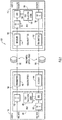
- FIG. 1 is a block diagram of a network topology 100 using optical fiber and an equalization process designed to equalize received signals that were transmitted via a copper cable in accordance with an example embodiment.
- Host A 110 is communicatively coupled with host B 112 via multimode optical fiber 120, which may be of the OM1/OM2 variety.
- Host A 110 includes a physical (PHY) 130 component (e.g., a chip or chip set configured for switching or routing).
- PHY 130 On a transmit side, PHY 130 includes a clock and data recovery (CDR) module 132, and on the receive side, PHY 130 includes an electronic dispersion compensation (EDC) module 134 and another CDR module 132.
- the transmit side of PHY 130 receives data at, e.g., a 10G rate.
- Host A 110 further includes an optics module 140 which may be, e.g., a 10G-LRM small form factor pluggable device that plugs into PHY 130, or a small form factor pluggable device that has a linear transfer function in its optical-to-electrical conversion portion.
- Optics module 140 includes an optical transmitter 142 that converts electronic signals into optical signals suitable to be transmitted over optical fiber 120.
- Optics module 140 also includes a receiver 144 that converts optical signals received via optical fiber 120 into electrical signals that are then supplied to EDC module 134 and CDR module 132 on the receive side of PHY 130.
- Host B 112 comprises similar elements as host A 110, and for purposes of brevity will not be described separately.
- PHY 130 still further includes EDC selection logic 180, the function of which is described in detail below in connection with FIG. 6 .
- EDC selection logic 180 is configured to determine whether an optics module 140 is plugged into the PHY 130, and when an optics module is plugged into the PHY, and supports 10G-LRM optics, to cause the EDC module 140 to apply an equalization process, to the 10G data, designed to equalize received signals that were transmitted via a copper cable (i.e., not optical cable).
- OM1/OM2 fibers are still widely present within campuses/enterprises/buildings and some customers are reluctant to pull new fiber to deploy 10GbE.
- Distances up to 220m over legacy OM1/OM2 fibers, for 10GbE, can be covered by using 10G-LRM optics.
- LRM equalizer a specific electronic dispersion compensation equalizer
- DAC Direct Attach Copper
- EDC selection logic 180 is configured to enable the equalizer for data sent via DAC cable to process data received via the optics module 140. This scheme thus provides 10G 220m support over OM1/OM2 fibers.
- Supporting OM1/OM2 multimode fiber links on 10/25G platforms provides users with an operational 10G network with existing OM1/OM2 fiber.
- FIGs. 2A is an eye diagram showing signals sent via LRM optics without the aid of an LRM equalizer. As can be seen (compared to FIG. 2B , for example), there is relatively little discernment among the individual waveforms, making subsequent decoding more error prone.
- FIG. 2B is an eye diagram showing signals sent via LRM optics (and recovered after been propagated through OM1 optical fiber) aided by equalization designed to equalize received signals that were transmitted via a copper cable in accordance with an example embodiment. As can be seen, there is significantly less noise or distortion among the individual waveforms, thus leading to improved subsequent decoding. Note, again, that the equalization that was applied to obtain the eye diagram of FIG. 2B is equalization optimized for signals transmitted via copper cable, e.g., DAC cables.
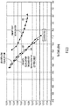
- FIG. 3 is a graph depicting bit error rate (BER) scenarios for signals sent via LRM optics with no equalization, signals sent via LRM optics aided by an LRM equalizer, and signals send via LRM optics and aided by equalization designed to equalize received signals that were transmitted via a copper cable in accordance with an example embodiment. More specifically, curve 310 represents LRM optics alone (without any equalization). This approach does not meet a target BER of, e.g., 1e-12 over OM1 optical fiber.
- BER bit error rate
- curve 320 represents signals sent via LRM optics and aided by an LRM equalizer
- curve 330 represents signals sent via LRM optics and aided by an equalizer optimized for signals transmitted via, e.g., DAC cables. Both of these latter approaches show similar performances, showing the effectiveness of an equalizer not designed to handle signals transmitted over optical fiber, such as an equalizer designed to equalize signals received via DAC cables.
- 10G-LRM optics (IEEE 802.3aq) are specified to support stressed sensitivity tests that are meant to emulate the OM1 worst-case channel responses.
- Such channel responses can be divided into the following groups: precursor, split-symmetrical, and postcursor.
- 10G-LRM optics aided by an equalizer not designed to handle signals transmitted over optical fiber e.g., an equalizer optimized for DAC
- an equalizer optimized for DAC active on the 10/25G platform side
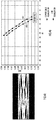
- FIG. 4A is an eye diagram showing a postcursor stressor signal measured at a receiver input of 10G-LRM optics in accordance with an example embodiment.
- the postcursor stressor signal is configured and calibrated to be in line with the IEEE 802.3aq standard specifications (Table 68-5).
- FIG. 4B is a graph that compares LRM equalization and equalization designed to equalize received signals that were transmitted via, e.g., a DAC cable after processing the postcursor stressor signal in accordance with an example embodiment.
- FIG. 5A is an eye diagram showing a precursor stressor signal measured at a receiver input of 10G-LRM optics in accordance with an example embodiment.
- the precursor stressor signal is configured and calibrated to be in line with the IEEE 802.3aq standard specifications (Table 68-5).
- FIG. 5B is a graph that compares LRM equalization and equalization designed to equalize received signals that were transmitted via a copper cable after processing the precursor stressor signal in accordance with an example embodiment.
- Curve 510 represents LRM equalization and curve 520 represents LRM optics aided by equalization designed to equalize signals transmitted via copper cable.
- FIG. 6 is a flowchart depicting a series of operations to allow signals received over optical fiber to be processed by an equalization process designed to equalize received signals that were transmitted via a copper cable in accordance with an example embodiment.
- a field removable unit such as a small form factor pluggable (SFP) device (e.g., optics module 140)
- SFP small form factor pluggable
- the host e.g., EDC selection logic 180
- the host e.g., EDC selection logic 180
- performs a FRU discovery routine e.g., the host PHY reads the FRU's EEPROM
- the host determines if the FRU is, e.g., a 10G-DAC. If yes, then at 616, the host configures its PHY for an equalizer optimized or designed for signals sent via DAC. And, at 618, the host turns on traffic to begin receiving data via the FRU.
- the FRU e.g., a 10G-DAC.
- the host determines, at 614, that the FRU is not a DAC FRU, then at 620 the host determines if the FRU is a limiting pluggable device (e.g., a short reach (SR) or long reach (LR)) FRU. If yes, then at 622, the host configures its PHY for a limiting equalizer. At 624, the host begins digital optical monitoring. And, at 626, the host turns on traffic to begin receiving data via the FRU.
- SR short reach
- LR long reach
- the host determines, at 620, that the FRU is not a limiting pluggable device, then at 630 the host determines if the FRU is a 10G-LRM FRU pluggable device. If not, the host concludes, at 632, that the FRU is not supported. If the FRU is a 10G-LRM FRU (pluggable device), then at 634, the host configures its PHY for an equalizer optimized or designed for signals sent via copper cable (e.g., DAC). At 636, the host begins digital optical monitoring. And, at 638, the host turns on traffic to begin receiving data via the FRU.
- 10G-LRM FRU pluggable device
- FIG. 7 is another flowchart depicting a series of operations for processing signal that was transmitted over an optical fiber in accordance with an example embodiment.
- a host or PHY of a host, obtains an electrical signal derived from optical-to-electrical conversion of an optical signal that was transmitted over, and received from, an optical fiber.
- the host applies an equalization process to the electrical signal, wherein the equalization process is of a type that is designed to equalize received signals that were transmitted via a copper cable.
- FIG. 8 depicts a device (e.g., host 110 A or host B 112) that executes EDC selection logic 180 in accordance with an example embodiment. It should be appreciated that FIG. 8 provides only an illustration of one embodiment and does not imply any limitations with regard to the environments in which different embodiments may be implemented. Many modifications to the depicted environment may be made. Indeed, in many implementations of a device configured to host EDC selection logic 180, much of the hardware described below may not be needed.
- the device 800 includes a bus 812, which provides communications between computer processor(s) 814, memory 816, persistent storage 818, communications unit 820, and input/output (I/O) interface(s) 822.
- Bus 812 can be implemented with any architecture designed for passing data and/or control information between processors (such as microprocessors, communications and network processors, etc.), system memory, peripheral devices, and any other hardware components within a system.
- processors such as microprocessors, communications and network processors, etc.
- system memory such as microprocessors, communications and network processors, etc.
- peripheral devices such as Ethernet drives, etc.
- bus 812 can be implemented with one or more buses.
- Memory 816 and persistent storage 818 are computer readable storage media.
- memory 816 includes random access memory (RAM) 824 and cache memory 826.
- RAM random access memory
- cache memory 826 In general, memory 816 can include any suitable volatile or non-volatile computer readable storage media. Instructions for the EDC selection logic 180 may be stored in memory 816 or persistent storage 818 for execution by processor(s) 814.
- One or more programs may be stored in persistent storage 818 for execution by one or more of the respective computer processors 814 via one or more memories of memory 816.
- the persistent storage 818 may be a magnetic hard disk drive, a solid state hard drive, a semiconductor storage device, read-only memory (ROM), erasable programmable read-only memory (EPROM), flash memory, or any other computer readable storage media that is capable of storing program instructions or digital information.
- the media used by persistent storage 818 may also be removable.
- a removable hard drive may be used for persistent storage 818.
- Other examples include optical and magnetic disks, thumb drives, and smart cards that are inserted into a drive for transfer onto another computer readable storage medium that is also part of persistent storage 818.
- Communications unit 820 in these examples, provides for communications with other data processing systems or devices.
- communications unit 820 includes one or more network interface cards.
- Communications unit 820 may provide communications through the use of either or both physical and wireless communications links.
- I/O interface(s) 822 allows for input and output of data with other devices that may be connected to computer device 800.
- I/O interface 822 may provide a connection to external devices 828 such as a keyboard, keypad, a touch screen, and/or some other suitable input device.
- external devices 828 can also include portable computer readable storage media such as database systems, thumb drives, portable optical or magnetic disks, and memory cards.
- I/O interface(s) 822 may also connect to a display 830.
- Display 830 provides a mechanism to display data to a user and may be, for example, a computer monitor.
- Data relating to operations described herein may be stored within any conventional or other data structures (e.g., files, arrays, lists, stacks, queues, records, etc.) and may be stored in any desired storage unit (e.g., database, data or other repositories, queue, etc.).
- the data transmitted between entities may include any desired format and arrangement, and may include any quantity of any types of fields of any size to store the data.
- the definition and data model for any datasets may indicate the overall structure in any desired fashion (e.g., computer-related languages, graphical representation, listing, etc.).
- the present embodiments may employ any number of any type of user interface (e.g., Graphical User Interface (GUI), command-line, prompt, etc.) for obtaining or providing information (e.g., data relating to scraping network sites), where the interface may include any information arranged in any fashion.
- GUI Graphical User Interface
- the interface may include any number of any types of input or actuation mechanisms (e.g., buttons, icons, fields, boxes, links, etc.) disposed at any locations to enter/display information and initiate desired actions via any suitable input devices (e.g., mouse, keyboard, etc.).
- the interface screens may include any suitable actuators (e.g., links, tabs, etc.) to navigate between the screens in any fashion.
- the environment of the present embodiments may include any number of computer or other processing systems (e.g., client or end-user systems, server systems, etc.) and databases or other repositories arranged in any desired fashion, where the present embodiments may be applied to any desired type of computing environment (e.g., cloud computing, client-server, network computing, mainframe, stand-alone systems, etc.).
- the computer or other processing systems employed by the present embodiments may be implemented by any number of any personal or other type of computer or processing system (e.g., desktop, laptop, PDA, mobile devices, etc.), and may include any commercially available operating system and any combination of commercially available and custom software (e.g., machine learning software, etc.).
- These systems may include any types of monitors and input devices (e.g., keyboard, mouse, voice recognition, etc.) to enter and/or view information.
- Each of the elements described herein may couple to and/or interact with one another through interfaces and/or through any other suitable connection (wired or wireless) that provides a viable pathway for communications.
- Interconnections, interfaces, and variations thereof discussed herein may be utilized to provide connections among elements in a system and/or may be utilized to provide communications, interactions, operations, etc. among elements that may be directly or indirectly connected in the system. Any combination of interfaces can be provided for elements described herein in order to facilitate operations as discussed for various embodiments described herein.
- the various functions of the computer or other processing systems may be distributed in any manner among any number of software and/or hardware modules or units, processing or computer systems and/or circuitry, where the computer or processing systems may be disposed locally or remotely of each other and communicate via any suitable communications medium (e.g., LAN, WAN, Intranet, Internet, hardwire, modem connection, wireless, etc.).
- any suitable communications medium e.g., LAN, WAN, Intranet, Internet, hardwire, modem connection, wireless, etc.
- the functions of the present embodiments may be distributed in any manner among the various end-user/client and server systems, and/or any other intermediary processing devices.
- the software and/or algorithms described above and illustrated in the flow charts may be modified in any manner that accomplishes the functions described herein.
- the functions in the flow charts or description may be performed in any order that accomplishes a desired operation.
- the software of the present embodiments may be available on a non-transitory computer useable medium (e.g., magnetic or optical mediums, magneto-optic mediums, floppy diskettes, CD-ROM, DVD, memory devices, etc.) of a stationary or portable program product apparatus or device for use with stand-alone systems or systems connected by a network or other communications medium.
- a non-transitory computer useable medium e.g., magnetic or optical mediums, magneto-optic mediums, floppy diskettes, CD-ROM, DVD, memory devices, etc.
- the communication network may be implemented by any number of any type of communications network (e.g., LAN, WAN, Internet, Intranet, VPN, etc.).
- the computer or other processing systems of the present embodiments may include any conventional or other communications devices to communicate over the network via any conventional or other protocols.
- the computer or other processing systems may utilize any type of connection (e.g., wired, wireless, etc.) for access to the network.
- Local communication media may be implemented by any suitable communication media (e.g., local area network (LAN), hardwire, wireless link, Intranet, etc.).
- the system may employ any number of any conventional or other databases, data stores or storage structures (e.g., files, databases, data structures, data or other repositories, etc.) to store information.
- the database system may be implemented by any number of any conventional or other databases, data stores or storage structures (e.g., files, databases, data structures, data or other repositories, etc.) to store information.
- the database system may be included within or coupled to the server and/or client systems.
- the database systems and/or storage structures may be remote from or local to the computer or other processing systems, and may store any desired data.
- the embodiments presented may be in various forms, such as a system, a method, and/or a computer program product at any possible technical detail level of integration
- the computer program product may include a computer readable storage medium (or media) having computer readable program instructions thereon for causing a processor to carry out aspects of presented herein.
- the computer readable storage medium can be a tangible device that can retain and store instructions for use by an instruction execution device.
- the computer readable storage medium may be, for example, but is not limited to, an electronic storage device, a magnetic storage device, an optical storage device, an electromagnetic storage device, a semiconductor storage device, or any suitable combination of the foregoing.
- a non-exhaustive list of more specific examples of the computer readable storage medium includes the following: a portable computer diskette, a hard disk, a random access memory (RAM), a read-only memory (ROM), an erasable programmable read-only memory (EPROM or Flash memory), a static random access memory (SRAM), a portable compact disc read-only memory (CD-ROM), a digital versatile disk (DVD), a memory stick, a floppy disk, a mechanically encoded device such as punch-cards or raised structures in a groove having instructions recorded thereon, and any suitable combination of the foregoing.
- RAM random access memory
- ROM read-only memory
- EPROM or Flash memory erasable programmable read-only memory
- SRAM static random access memory
- CD-ROM compact disc read-only memory
- DVD digital versatile disk
- memory stick a floppy disk
- a mechanically encoded device such as punch-cards or raised structures in a groove having instructions recorded thereon
- a computer readable storage medium is not to be construed as being transitory signals per se, such as radio waves or other freely propagating electromagnetic waves, electromagnetic waves propagating through a waveguide or other transmission media (e.g., light pulses passing through a fiber-optic cable), or electrical signals transmitted through a wire.
- Computer readable program instructions described herein can be downloaded to respective computing/processing devices from a computer readable storage medium or to an external computer or external storage device via a network, for example, the Internet, a local area network, a wide area network and/or a wireless network.
- the network may comprise copper transmission cables, optical transmission fibers, wireless transmission, routers, firewalls, switches, gateway computers and/or edge servers.
- a network adapter card or network interface in each computing/processing device receives computer readable program instructions from the network and forwards the computer readable program instructions for storage in a computer readable storage medium within the respective computing/processing device.
- Computer readable program instructions for carrying out operations of the present embodiments may be assembler instructions, instruction-set-architecture (ISA) instructions, machine instructions, machine dependent instructions, microcode, firmware instructions, state-setting data, configuration data for integrated circuitry, or either source code or object code written in any combination of one or more programming languages, including an object oriented programming language such as Python, C++, or the like, and procedural programming languages, such as the "C" programming language or similar programming languages.
- the computer readable program instructions may execute entirely on the user's computer, partly on the user's computer, as a stand-alone software package, partly on the user's computer and partly on a remote computer or entirely on the remote computer or server.
- the remote computer may be connected to the user's computer through any type of network, including a local area network (LAN) or a wide area network (WAN), or the connection may be made to an external computer (for example, through the Internet using an Internet Service Provider).
- electronic circuitry including, for example, programmable logic circuitry, field-programmable gate arrays (FPGA), or programmable logic arrays (PLA) may execute the computer readable program instructions by utilizing state information of the computer readable program instructions to personalize the electronic circuitry, in order to perform aspects presented herein.
- These computer readable program instructions may be provided to a processor of a general purpose computer, special purpose computer, or other programmable data processing apparatus to produce a machine, such that the instructions, which execute via the processor of the computer or other programmable data processing apparatus, create means for implementing the functions/acts specified in the flowchart and/or block diagram block or blocks.
- These computer readable program instructions may also be stored in a computer readable storage medium that can direct a computer, a programmable data processing apparatus, and/or other devices to function in a particular manner, such that the computer readable storage medium having instructions stored therein comprises an article of manufacture including instructions which implement aspects of the function/act specified in the flowchart and/or block diagram block or blocks.
- the computer readable program instructions may also be loaded onto a computer, other programmable data processing apparatus, or other device to cause a series of operational steps to be performed on the computer, other programmable apparatus or other device to produce a computer implemented process, such that the instructions which execute on the computer, other programmable apparatus, or other device implement the functions/acts specified in the flowchart and/or block diagram block or blocks.
- each block in the flowchart or block diagrams may represent a module, segment, or portion of instructions, which comprises one or more executable instructions for implementing the specified logical function(s).
- the functions noted in the blocks may occur out of the order noted in the figures. For example, two blocks shown in succession may, in fact, be executed substantially concurrently, or the blocks may sometimes be executed in the reverse order, depending upon the functionality involved.
- a method in one form, includes obtaining an electrical signal derived from optical-to-electrical conversion of an optical signal that was transmitted over, and received from, an optical fiber; and applying an equalization process to the electrical signal, wherein the equalization process is of a type that is designed to equalize received signals that were transmitted via a copper cable.
- the equalization process is configured to not be fully optimized to compensate for an optical channel response resulting in a split-symmetrical output pulse.
- the equalization process is configured to compensate for an optical channel response resulting in an optical pulse with pre-cursor components
- the equalization process is configured to compensate for an optical channel response resulting in an optical pulse with post-cursor components.
- the equalization process may be optimized for equalizing signals obtained via a direct attach copper (DAC) cable.
- DAC direct attach copper
- the optical signal may be received via an OM1 or an OM2 optical fiber.
- optical signal carries Ethernet frames at at least 10 gigabits/second.
- the optical-to-electrical conversion has a linear transfer function.
- the optical-to-electrical conversion is obtained through a device that is compliant with IEEE 802.3aq.
- the device may be a small form factor pluggable device.
- the method may further include selecting the equalization process in response to detecting that the device has been plugged into a host.
- an apparatus may also be provided in accordance with an embodiment.
- the apparatus may include a network interface unit configured to enable communications via a network; a memory configured to store logic instructions; and a processor, when executing the logic instructions, configured to: obtain an electrical signal derived from optical-to-electrical conversion of an optical signal that was transmitted over, and received from, an optical fiber; and apply an equalization process to the electrical signal, wherein the equalization process is of a type that is designed to equalize received signals that were transmitted via a copper cable.
- the equalization process may be optimized for equalizing signals obtained via a direct attach copper (DAC) cable.
- DAC direct attach copper
- the optical signal may be received via an OM1 or an OM2 optical fiber.
- the optical signal carries Ethernet frames at at least 10 gigabits/second.
- the optical-to-electrical conversion may be obtained through a device that is compliant with IEEE 802.3aq.
- the apparatus includes a PHY portion
- the processor is further configured to select the equalization process in response to detecting that a device has been plugged into the PHY portion
- a non-transitory computer readable storage media is provided that is encoded with instructions that, when executed by a processor, cause the processor to obtain an electrical signal derived from optical-to-electrical conversion of an optical signal that was transmitted over, and received from, an optical fiber; and apply an equalization process to the electrical signal, wherein the equalization process is of a type that is designed to equalize received signals that were transmitted via a copper cable.
- the equalization process may be optimized for equalizing signals obtained via a direct attach copper (DAC) cable.
- DAC direct attach copper
Landscapes
- Physics & Mathematics (AREA)
- Electromagnetism (AREA)
- Engineering & Computer Science (AREA)
- Computer Networks & Wireless Communication (AREA)
- Signal Processing (AREA)
- Spectroscopy & Molecular Physics (AREA)
- Optical Communication System (AREA)
Abstract
Description
- The present disclosure relates to data networking using optical fiber, and more particularly to selectively applying an equalization process to signals received via the optical fiber.
- Optical multi-mode (OM) fibers are described using a system of classification determined by the ISO 11801 standard, and are presently classified as OM1, OM2, OM3, and OM4. OM1 has a core/cladding relationship of 62.5/125 µm, and OM2 has a core/cladding relationship of 50/125 µm. These fibers support applications ranging from Ethernet (10 Mbit/s) to Gigabit Ethernet (1 Gbit/s) and, because of their relatively large core size, are suitable for use with LED transmitters. Newer deployments often use laser-optimized 50/125 µm multi-mode fiber, called OM3. Fibers that meet this latter standard provide sufficient bandwidth to support 10 Gigabit Ethernet (GbE) up to 300 meters. Optical fiber manufacturers have greatly refined their manufacturing processes since the ISO 11801 standard was issued, and cables are presently being made that support 10 GbE up to 550 meters, and such cables are designated as OM4. OM3 and OM4 fiber is now also used for 25GbE, thus providing 10/25GbE data rates.
- Notably, OM1 and OM2 fibers are still widely present within the networking infrastructure of campuses/enterprises/buildings and it is not uncommon for customers to be reluctant to purchase and install new (i.e., OM3, OM4) fiber to deploy 10GbE (or 25GbE). Presently, distances up to 220m over OM1/OM2 fibers can be covered by using lOG-long reach multi-mode (LRM) optics. In many implementations, signals transported over OM1/OM2 via 10G-LRM are then processed with, among other things, electronic dispersion compensation (EDC) that is optimized for such optically transported signals.
-
-
FIG. 1 is a block diagram of a network topology using optical fiber and an equalization process designed to equalize received signals that were transmitted via a copper cable in accordance with an example embodiment. -
FIGs. 2A is an eye diagram showing signals sent via LRM optics without equalization. -
FIG. 2B is an eye diagram showing signals sent via LRM optics with equalization designed to equalize received signals that were transmitted via a copper cable in accordance with an example embodiment. -
FIG. 3 is a graph comparing bit error rate scenarios for signals sent via LRM optics with no equalization, signals sent via LRM optics and aided by LRM equalization, and signals sent via LRM optics and aided by equalization designed to equalize received signals that were transmitted via a copper cable in accordance with an example embodiment. -
FIG. 4A is an eye diagram showing a postcursor stressor signal measured at a receiver input of 10G-LRM optics in accordance with an example embodiment. -
FIG. 4B is a graph that compares LRM equalization and equalization designed to equalize received signals that were transmitted via a copper cable after processing the postcursor stressor signal in accordance with an example embodiment. -
FIG. 5A is an eye diagram showing a precursor stressor signal measured at a receiver input of 10G-LRM in accordance with an example embodiment. -
FIG. 5B is a graph that compares LRM equalization and equalization designed to equalize received signals that were transmitted via a copper cable after processing the precursor stressor signal in accordance with an example embodiment. -
FIG. 6 is a flowchart depicting a series of operations to allow signals received over optical fiber to be processed by equalization designed to equalize received signals that were transmitted via a copper cable in accordance with an example embodiment. -
FIG. 7 is another flowchart depicting a series of operations for processing a signal that was transmitted over an optical fiber in accordance with an example embodiment. -
FIG. 8 illustrates a device in accordance with an example embodiment. - Presented herein are methodologies for using legacy optical fiber for 10 Gigabit Ethernet or higher data rates. The methodology includes obtaining an electrical signal derived from optical-to-electrical conversion of an optical signal that was transmitted over, and received from, an optical fiber; and applying an equalization process to the electrical signal, wherein the equalization process is of a type that is designed to equalize received signals that were transmitted via a copper cable.
- A device or apparatus is also described. The device may include a network interface unit configured to enable communications via a network; a memory configured to store logic instructions; and a processor, when executing the logic instructions, configured to: obtain an electrical signal derived from optical-to-electrical conversion of an optical signal that was transmitted over, and received from, an optical fiber; and apply an equalization process to the electrical signal, wherein the equalization process is of a type that is designed to equalize received signals that were transmitted via a copper cable.
-
FIG. 1 is a block diagram of anetwork topology 100 using optical fiber and an equalization process designed to equalize received signals that were transmitted via a copper cable in accordance with an example embodiment.Host A 110 is communicatively coupled withhost B 112 via multimodeoptical fiber 120, which may be of the OM1/OM2 variety.Host A 110 includes a physical (PHY) 130 component (e.g., a chip or chip set configured for switching or routing). On a transmit side,PHY 130 includes a clock and data recovery (CDR)module 132, and on the receive side,PHY 130 includes an electronic dispersion compensation (EDC)module 134 and anotherCDR module 132. As shown, the transmit side ofPHY 130 receives data at, e.g., a 10G rate. -
Host A 110 further includes anoptics module 140 which may be, e.g., a 10G-LRM small form factor pluggable device that plugs intoPHY 130, or a small form factor pluggable device that has a linear transfer function in its optical-to-electrical conversion portion.Optics module 140 includes anoptical transmitter 142 that converts electronic signals into optical signals suitable to be transmitted overoptical fiber 120.Optics module 140 also includes areceiver 144 that converts optical signals received viaoptical fiber 120 into electrical signals that are then supplied toEDC module 134 andCDR module 132 on the receive side ofPHY 130. -
Host B 112 comprises similar elements ashost A 110, and for purposes of brevity will not be described separately. - PHY 130 still further includes
EDC selection logic 180, the function of which is described in detail below in connection withFIG. 6 . At a high level,EDC selection logic 180 is configured to determine whether anoptics module 140 is plugged into thePHY 130, and when an optics module is plugged into the PHY, and supports 10G-LRM optics, to cause theEDC module 140 to apply an equalization process, to the 10G data, designed to equalize received signals that were transmitted via a copper cable (i.e., not optical cable). - As noted, OM1/OM2 fibers are still widely present within campuses/enterprises/buildings and some customers are reluctant to pull new fiber to deploy 10GbE. Distances up to 220m over legacy OM1/OM2 fibers, for 10GbE, can be covered by using 10G-LRM optics.
- Notably, 10G-LRM optics require platforms equipped with a specific electronic dispersion compensation equalizer (called hereafter "LRM equalizer").
- As newer OM3/OM4 optical fiber supplants the older OM1/OM2 optical fiber, chip manufacturers are phasing out platforms with the specific "LRM equalizer". As such, in a transition from 10G to newer 10/25G platforms, 10G legacy OM1/OM2 multimode links will fall short.
- At the same time, those same chip manufacturers may still provide an equalizer designed to equalize received signals that were transmitted via a copper cable (i.e., not optical cable). More specifically, a PHY in a given host may be configured to also support what is known as Direct Attach Copper (DAC) cables, and 10G data transmitted via DAC.
- In accordance with an embodiment, in the event PHY 130 on, e.g.,
host B 112, does not support LRM equalization, and yetoptics module 140 is plugged into thePHY 130,EDC selection logic 180 is configured to enable the equalizer for data sent via DAC cable to process data received via theoptics module 140. This scheme thus provides 10G 220m support over OM1/OM2 fibers. - Supporting OM1/OM2 multimode fiber links on 10/25G platforms (not equipped with a LRM equalizer) provides users with an operational 10G network with existing OM1/OM2 fiber.
-
FIGs. 2A is an eye diagram showing signals sent via LRM optics without the aid of an LRM equalizer. As can be seen (compared toFIG. 2B , for example), there is relatively little discernment among the individual waveforms, making subsequent decoding more error prone. -
FIG. 2B is an eye diagram showing signals sent via LRM optics (and recovered after been propagated through OM1 optical fiber) aided by equalization designed to equalize received signals that were transmitted via a copper cable in accordance with an example embodiment. As can be seen, there is significantly less noise or distortion among the individual waveforms, thus leading to improved subsequent decoding. Note, again, that the equalization that was applied to obtain the eye diagram ofFIG. 2B is equalization optimized for signals transmitted via copper cable, e.g., DAC cables. - In this same vein,
FIG. 3 is a graph depicting bit error rate (BER) scenarios for signals sent via LRM optics with no equalization, signals sent via LRM optics aided by an LRM equalizer, and signals send via LRM optics and aided by equalization designed to equalize received signals that were transmitted via a copper cable in accordance with an example embodiment. More specifically,curve 310 represents LRM optics alone (without any equalization). This approach does not meet a target BER of, e.g., 1e-12 over OM1 optical fiber. On the other hand,curve 320 represents signals sent via LRM optics and aided by an LRM equalizer, andcurve 330 represents signals sent via LRM optics and aided by an equalizer optimized for signals transmitted via, e.g., DAC cables. Both of these latter approaches show similar performances, showing the effectiveness of an equalizer not designed to handle signals transmitted over optical fiber, such as an equalizer designed to equalize signals received via DAC cables. - 10G-LRM optics (IEEE 802.3aq) are specified to support stressed sensitivity tests that are meant to emulate the OM1 worst-case channel responses. Such channel responses can be divided into the following groups: precursor, split-symmetrical, and postcursor.
- In a case wherein a mode conditioning patchcord is used at launch, it has been found that 5% of the links (considering the fiber distribution used within the 802.3aq standard) are potentially representative of a split-symmetrical channel response.
- It has also been found that 10G-LRM optics aided by an equalizer not designed to handle signals transmitted over optical fiber (e.g., an equalizer optimized for DAC), active on the 10/25G platform side, is able to support a pre-cursor and a post-cursor channel response.
- Thus, the solution described herein enables the following coverage:
- 100% of 220m OM2 links
- 95% of 220m OM1 links (due to the split-symmetrical channel response)
-
FIG. 4A is an eye diagram showing a postcursor stressor signal measured at a receiver input of 10G-LRM optics in accordance with an example embodiment. The postcursor stressor signal is configured and calibrated to be in line with the IEEE 802.3aq standard specifications (Table 68-5). -
FIG. 4B is a graph that compares LRM equalization and equalization designed to equalize received signals that were transmitted via, e.g., a DAC cable after processing the postcursor stressor signal in accordance with an example embodiment.Curve 410 represents LRM equalization andcurve 420 represents LRM optics aided by equalization designed to equalize signals transmitted via copper cable. As can be seen,curve 420 andcurve 410 show similar performance with a 1dB penalty at BER=1e-12 forcurve 420. -
FIG. 5A is an eye diagram showing a precursor stressor signal measured at a receiver input of 10G-LRM optics in accordance with an example embodiment. The precursor stressor signal is configured and calibrated to be in line with the IEEE 802.3aq standard specifications (Table 68-5). -
FIG. 5B is a graph that compares LRM equalization and equalization designed to equalize received signals that were transmitted via a copper cable after processing the precursor stressor signal in accordance with an example embodiment.Curve 510 represents LRM equalization andcurve 520 represents LRM optics aided by equalization designed to equalize signals transmitted via copper cable. As can be seen,curve 420 andcurve 410 show similar performance with a 1.5dB penalty at BER=1e-12 forcurve 520. -
FIG. 6 is a flowchart depicting a series of operations to allow signals received over optical fiber to be processed by an equalization process designed to equalize received signals that were transmitted via a copper cable in accordance with an example embodiment. At 610, a field removable unit (FRU), such as a small form factor pluggable (SFP) device (e.g., optics module 140), is plugged into a host PHY. At 612, the host (e.g., EDC selection logic 180) performs a FRU discovery routine (e.g., the host PHY reads the FRU's EEPROM) to determine what kind of device has just been plugged in. - At 614, the host determines if the FRU is, e.g., a 10G-DAC. If yes, then at 616, the host configures its PHY for an equalizer optimized or designed for signals sent via DAC. And, at 618, the host turns on traffic to begin receiving data via the FRU.
- If, on the other hand, the host determines, at 614, that the FRU is not a DAC FRU, then at 620 the host determines if the FRU is a limiting pluggable device (e.g., a short reach (SR) or long reach (LR)) FRU. If yes, then at 622, the host configures its PHY for a limiting equalizer. At 624, the host begins digital optical monitoring. And, at 626, the host turns on traffic to begin receiving data via the FRU.
- If, at 620, the host determines, at 620, that the FRU is not a limiting pluggable device, then at 630 the host determines if the FRU is a 10G-LRM FRU pluggable device. If not, the host concludes, at 632, that the FRU is not supported. If the FRU is a 10G-LRM FRU (pluggable device), then at 634, the host configures its PHY for an equalizer optimized or designed for signals sent via copper cable (e.g., DAC). At 636, the host begins digital optical monitoring. And, at 638, the host turns on traffic to begin receiving data via the FRU.
-
FIG. 7 is another flowchart depicting a series of operations for processing signal that was transmitted over an optical fiber in accordance with an example embodiment. At 710, a host, or PHY of a host, obtains an electrical signal derived from optical-to-electrical conversion of an optical signal that was transmitted over, and received from, an optical fiber. At 712, the host applies an equalization process to the electrical signal, wherein the equalization process is of a type that is designed to equalize received signals that were transmitted via a copper cable. -
FIG. 8 depicts a device (e.g., host 110 A or host B 112) that executesEDC selection logic 180 in accordance with an example embodiment. It should be appreciated thatFIG. 8 provides only an illustration of one embodiment and does not imply any limitations with regard to the environments in which different embodiments may be implemented. Many modifications to the depicted environment may be made. Indeed, in many implementations of a device configured to hostEDC selection logic 180, much of the hardware described below may not be needed. - As depicted, the
device 800 includes abus 812, which provides communications between computer processor(s) 814,memory 816,persistent storage 818,communications unit 820, and input/output (I/O) interface(s) 822.Bus 812 can be implemented with any architecture designed for passing data and/or control information between processors (such as microprocessors, communications and network processors, etc.), system memory, peripheral devices, and any other hardware components within a system. For example,bus 812 can be implemented with one or more buses. -
Memory 816 andpersistent storage 818 are computer readable storage media. In the depicted embodiment,memory 816 includes random access memory (RAM) 824 andcache memory 826. In general,memory 816 can include any suitable volatile or non-volatile computer readable storage media. Instructions for theEDC selection logic 180 may be stored inmemory 816 orpersistent storage 818 for execution by processor(s) 814. - One or more programs may be stored in
persistent storage 818 for execution by one or more of therespective computer processors 814 via one or more memories ofmemory 816. Thepersistent storage 818 may be a magnetic hard disk drive, a solid state hard drive, a semiconductor storage device, read-only memory (ROM), erasable programmable read-only memory (EPROM), flash memory, or any other computer readable storage media that is capable of storing program instructions or digital information. - The media used by
persistent storage 818 may also be removable. For example, a removable hard drive may be used forpersistent storage 818. Other examples include optical and magnetic disks, thumb drives, and smart cards that are inserted into a drive for transfer onto another computer readable storage medium that is also part ofpersistent storage 818. -
Communications unit 820, in these examples, provides for communications with other data processing systems or devices. In these examples,communications unit 820 includes one or more network interface cards.Communications unit 820 may provide communications through the use of either or both physical and wireless communications links. - I/O interface(s) 822 allows for input and output of data with other devices that may be connected to
computer device 800. For example, I/O interface 822 may provide a connection toexternal devices 828 such as a keyboard, keypad, a touch screen, and/or some other suitable input device.External devices 828 can also include portable computer readable storage media such as database systems, thumb drives, portable optical or magnetic disks, and memory cards. - Software and data used to practice embodiments can be stored on such portable computer readable storage media and can be loaded onto
persistent storage 818 via I/O interface(s) 822. I/O interface(s) 822 may also connect to adisplay 830.Display 830 provides a mechanism to display data to a user and may be, for example, a computer monitor. - The programs described herein are identified based upon the application for which they are implemented in a specific embodiment. However, it should be appreciated that any particular program nomenclature herein is used merely for convenience, and thus the embodiments should not be limited to use solely in any specific application identified and/or implied by such nomenclature.
- Data relating to operations described herein may be stored within any conventional or other data structures (e.g., files, arrays, lists, stacks, queues, records, etc.) and may be stored in any desired storage unit (e.g., database, data or other repositories, queue, etc.). The data transmitted between entities may include any desired format and arrangement, and may include any quantity of any types of fields of any size to store the data. The definition and data model for any datasets may indicate the overall structure in any desired fashion (e.g., computer-related languages, graphical representation, listing, etc.).
- The present embodiments may employ any number of any type of user interface (e.g., Graphical User Interface (GUI), command-line, prompt, etc.) for obtaining or providing information (e.g., data relating to scraping network sites), where the interface may include any information arranged in any fashion. The interface may include any number of any types of input or actuation mechanisms (e.g., buttons, icons, fields, boxes, links, etc.) disposed at any locations to enter/display information and initiate desired actions via any suitable input devices (e.g., mouse, keyboard, etc.). The interface screens may include any suitable actuators (e.g., links, tabs, etc.) to navigate between the screens in any fashion.
- The environment of the present embodiments may include any number of computer or other processing systems (e.g., client or end-user systems, server systems, etc.) and databases or other repositories arranged in any desired fashion, where the present embodiments may be applied to any desired type of computing environment (e.g., cloud computing, client-server, network computing, mainframe, stand-alone systems, etc.). The computer or other processing systems employed by the present embodiments may be implemented by any number of any personal or other type of computer or processing system (e.g., desktop, laptop, PDA, mobile devices, etc.), and may include any commercially available operating system and any combination of commercially available and custom software (e.g., machine learning software, etc.). These systems may include any types of monitors and input devices (e.g., keyboard, mouse, voice recognition, etc.) to enter and/or view information.
- It is to be understood that the software of the present embodiments may be implemented in any desired computer language and could be developed by one of ordinary skill in the computer arts based on the functional descriptions contained in the specification and flow charts illustrated in the drawings. Further, any references herein of software performing various functions generally refer to computer systems or processors performing those functions under software control. The computer systems of the present embodiments may alternatively be implemented by any type of hardware and/or other processing circuitry.
- Each of the elements described herein may couple to and/or interact with one another through interfaces and/or through any other suitable connection (wired or wireless) that provides a viable pathway for communications. Interconnections, interfaces, and variations thereof discussed herein may be utilized to provide connections among elements in a system and/or may be utilized to provide communications, interactions, operations, etc. among elements that may be directly or indirectly connected in the system. Any combination of interfaces can be provided for elements described herein in order to facilitate operations as discussed for various embodiments described herein.
- The various functions of the computer or other processing systems may be distributed in any manner among any number of software and/or hardware modules or units, processing or computer systems and/or circuitry, where the computer or processing systems may be disposed locally or remotely of each other and communicate via any suitable communications medium (e.g., LAN, WAN, Intranet, Internet, hardwire, modem connection, wireless, etc.). For example, the functions of the present embodiments may be distributed in any manner among the various end-user/client and server systems, and/or any other intermediary processing devices. The software and/or algorithms described above and illustrated in the flow charts may be modified in any manner that accomplishes the functions described herein. In addition, the functions in the flow charts or description may be performed in any order that accomplishes a desired operation.
- The software of the present embodiments may be available on a non-transitory computer useable medium (e.g., magnetic or optical mediums, magneto-optic mediums, floppy diskettes, CD-ROM, DVD, memory devices, etc.) of a stationary or portable program product apparatus or device for use with stand-alone systems or systems connected by a network or other communications medium.
- The communication network may be implemented by any number of any type of communications network (e.g., LAN, WAN, Internet, Intranet, VPN, etc.). The computer or other processing systems of the present embodiments may include any conventional or other communications devices to communicate over the network via any conventional or other protocols. The computer or other processing systems may utilize any type of connection (e.g., wired, wireless, etc.) for access to the network. Local communication media may be implemented by any suitable communication media (e.g., local area network (LAN), hardwire, wireless link, Intranet, etc.).
- The system may employ any number of any conventional or other databases, data stores or storage structures (e.g., files, databases, data structures, data or other repositories, etc.) to store information. The database system may be implemented by any number of any conventional or other databases, data stores or storage structures (e.g., files, databases, data structures, data or other repositories, etc.) to store information. The database system may be included within or coupled to the server and/or client systems. The database systems and/or storage structures may be remote from or local to the computer or other processing systems, and may store any desired data.
- The embodiments presented may be in various forms, such as a system, a method, and/or a computer program product at any possible technical detail level of integration. The computer program product may include a computer readable storage medium (or media) having computer readable program instructions thereon for causing a processor to carry out aspects of presented herein.
- The computer readable storage medium can be a tangible device that can retain and store instructions for use by an instruction execution device. The computer readable storage medium may be, for example, but is not limited to, an electronic storage device, a magnetic storage device, an optical storage device, an electromagnetic storage device, a semiconductor storage device, or any suitable combination of the foregoing. A non-exhaustive list of more specific examples of the computer readable storage medium includes the following: a portable computer diskette, a hard disk, a random access memory (RAM), a read-only memory (ROM), an erasable programmable read-only memory (EPROM or Flash memory), a static random access memory (SRAM), a portable compact disc read-only memory (CD-ROM), a digital versatile disk (DVD), a memory stick, a floppy disk, a mechanically encoded device such as punch-cards or raised structures in a groove having instructions recorded thereon, and any suitable combination of the foregoing. A computer readable storage medium, as used herein, is not to be construed as being transitory signals per se, such as radio waves or other freely propagating electromagnetic waves, electromagnetic waves propagating through a waveguide or other transmission media (e.g., light pulses passing through a fiber-optic cable), or electrical signals transmitted through a wire.
- Computer readable program instructions described herein can be downloaded to respective computing/processing devices from a computer readable storage medium or to an external computer or external storage device via a network, for example, the Internet, a local area network, a wide area network and/or a wireless network. The network may comprise copper transmission cables, optical transmission fibers, wireless transmission, routers, firewalls, switches, gateway computers and/or edge servers. A network adapter card or network interface in each computing/processing device receives computer readable program instructions from the network and forwards the computer readable program instructions for storage in a computer readable storage medium within the respective computing/processing device.
- Computer readable program instructions for carrying out operations of the present embodiments may be assembler instructions, instruction-set-architecture (ISA) instructions, machine instructions, machine dependent instructions, microcode, firmware instructions, state-setting data, configuration data for integrated circuitry, or either source code or object code written in any combination of one or more programming languages, including an object oriented programming language such as Python, C++, or the like, and procedural programming languages, such as the "C" programming language or similar programming languages. The computer readable program instructions may execute entirely on the user's computer, partly on the user's computer, as a stand-alone software package, partly on the user's computer and partly on a remote computer or entirely on the remote computer or server. In the latter scenario, the remote computer may be connected to the user's computer through any type of network, including a local area network (LAN) or a wide area network (WAN), or the connection may be made to an external computer (for example, through the Internet using an Internet Service Provider). In some embodiments, electronic circuitry including, for example, programmable logic circuitry, field-programmable gate arrays (FPGA), or programmable logic arrays (PLA) may execute the computer readable program instructions by utilizing state information of the computer readable program instructions to personalize the electronic circuitry, in order to perform aspects presented herein.
- Aspects of the present embodiments are described herein with reference to flowchart illustrations and/or block diagrams of methods, apparatus (systems), and computer program products according to the embodiments. It will be understood that each block of the flowchart illustrations and/or block diagrams, and combinations of blocks in the flowchart illustrations and/or block diagrams, can be implemented by computer readable program instructions.
- These computer readable program instructions may be provided to a processor of a general purpose computer, special purpose computer, or other programmable data processing apparatus to produce a machine, such that the instructions, which execute via the processor of the computer or other programmable data processing apparatus, create means for implementing the functions/acts specified in the flowchart and/or block diagram block or blocks. These computer readable program instructions may also be stored in a computer readable storage medium that can direct a computer, a programmable data processing apparatus, and/or other devices to function in a particular manner, such that the computer readable storage medium having instructions stored therein comprises an article of manufacture including instructions which implement aspects of the function/act specified in the flowchart and/or block diagram block or blocks.
- The computer readable program instructions may also be loaded onto a computer, other programmable data processing apparatus, or other device to cause a series of operational steps to be performed on the computer, other programmable apparatus or other device to produce a computer implemented process, such that the instructions which execute on the computer, other programmable apparatus, or other device implement the functions/acts specified in the flowchart and/or block diagram block or blocks.
- The flowchart and block diagrams in the figures illustrate the architecture, functionality, and operation of possible implementations of systems, methods, and computer program products according to various embodiments. In this regard, each block in the flowchart or block diagrams may represent a module, segment, or portion of instructions, which comprises one or more executable instructions for implementing the specified logical function(s). In some alternative implementations, the functions noted in the blocks may occur out of the order noted in the figures. For example, two blocks shown in succession may, in fact, be executed substantially concurrently, or the blocks may sometimes be executed in the reverse order, depending upon the functionality involved. It will also be noted that each block of the block diagrams and/or flowchart illustration, and combinations of blocks in the block diagrams and/or flowchart illustration, can be implemented by special purpose hardware-based systems that perform the specified functions or acts or carry out combinations of special purpose hardware and computer instructions.
- In summary, in one form, a method is provided. The method includes obtaining an electrical signal derived from optical-to-electrical conversion of an optical signal that was transmitted over, and received from, an optical fiber; and applying an equalization process to the electrical signal, wherein the equalization process is of a type that is designed to equalize received signals that were transmitted via a copper cable.
- In an embodiment, the equalization process is configured to not be fully optimized to compensate for an optical channel response resulting in a split-symmetrical output pulse.
- In an embodiment, the equalization process is configured to compensate for an optical channel response resulting in an optical pulse with pre-cursor components
- In an embodiment, the equalization process is configured to compensate for an optical channel response resulting in an optical pulse with post-cursor components.
- The equalization process may be optimized for equalizing signals obtained via a direct attach copper (DAC) cable.
- In one implementation, the optical signal may be received via an OM1 or an OM2 optical fiber.
- In an implementation, wherein the optical signal carries Ethernet frames at at least 10 gigabits/second.
- In an embodiment, the optical-to-electrical conversion has a linear transfer function.
- In one implementation, the optical-to-electrical conversion is obtained through a device that is compliant with IEEE 802.3aq.
- In an embodiment, the device may be a small form factor pluggable device.
- In an embodiment, the method may further include selecting the equalization process in response to detecting that the device has been plugged into a host.
- In another form, an apparatus may also be provided in accordance with an embodiment. The apparatus may include a network interface unit configured to enable communications via a network; a memory configured to store logic instructions; and a processor, when executing the logic instructions, configured to: obtain an electrical signal derived from optical-to-electrical conversion of an optical signal that was transmitted over, and received from, an optical fiber; and apply an equalization process to the electrical signal, wherein the equalization process is of a type that is designed to equalize received signals that were transmitted via a copper cable.
- In an embodiment, the equalization process may be optimized for equalizing signals obtained via a direct attach copper (DAC) cable.
- In an embodiment, the optical signal may be received via an OM1 or an OM2 optical fiber.
- In an embodiment, the optical signal carries Ethernet frames at at least 10 gigabits/second.
- In an embodiment, the optical-to-electrical conversion may be obtained through a device that is compliant with IEEE 802.3aq.
- In an embodiment, the apparatus includes a PHY portion, and the processor is further configured to select the equalization process in response to detecting that a device has been plugged into the PHY portion
- In still another form, a non-transitory computer readable storage media is provided that is encoded with instructions that, when executed by a processor, cause the processor to obtain an electrical signal derived from optical-to-electrical conversion of an optical signal that was transmitted over, and received from, an optical fiber; and apply an equalization process to the electrical signal, wherein the equalization process is of a type that is designed to equalize received signals that were transmitted via a copper cable.
- In an embodiment, the equalization process may be optimized for equalizing signals obtained via a direct attach copper (DAC) cable.
- The descriptions of the various embodiments have been presented for purposes of illustration, but are not intended to be exhaustive or limited to the embodiments disclosed. Many modifications and variations will be apparent to those of ordinary skill in the art without departing from the scope of the claimed subject matter. The terminology used herein was chosen to best explain the principles of the embodiments, the practical application or technical improvement over technologies found in the marketplace, or to enable others of ordinary skill in the art to understand the embodiments disclosed herein.
Claims (15)
- A method comprising:obtaining an electrical signal derived from optical-to-electrical conversion of an optical signal that was transmitted over, and received from, an optical fiber; andapplying an equalization process to the electrical signal, wherein the equalization process is of a type that is designed to equalize received signals that were transmitted via a copper cable.
- The method of claim 1,
wherein the equalization process is configured to not be fully optimized to compensate for an optical channel response resulting in a split-symmetrical output pulse; or
wherein the equalization process is configured to compensate for an optical channel response resulting in an optical pulse with pre-cursor components; or
wherein the equalization process is configured to compensate for an optical channel response resulting in an optical pulse with post-cursor components - The method of claim 1, wherein the equalization process is optimized for equalizing signals obtained via a direct attach copper (DAC) cable.
- The method of claim 1 or 2, wherein the optical signal is received via an OM1 or an OM2 optical fiber, optionally wherein the optical fiber is at least 220 meters long.
- The method of any preceding claim, wherein the optical signal carries Ethernet frames at at least 10 gigabits/second.
- The method of any preceding claim, wherein the optical-to-electrical conversion has a linear transfer function.
- The method of any preceding claim, wherein the optical-to-electrical conversion is obtained through a device that is compliant with IEEE 802.3aq, optionally wherein the device is a small form factor pluggable device.
- The method of claim 7, further comprising selecting the equalization process in response to detecting that the device has been plugged into a host.
- An apparatus, comprising:a network interface unit configured to enable communications via a network;a memory configured to store logic instructions; anda processor, when executing the logic instructions, configured to:obtain an electrical signal derived from optical-to-electrical conversion of an optical signal that was transmitted over, and received from, an optical fiber; andapply an equalization process to the electrical signal, wherein the equalization process is of a type that is designed to equalize received signals that were transmitted via a copper cable.
- The apparatus of claim 9, wherein the equalization process is optimized for equalizing signals obtained via a direct attach copper (DAC) cable.
- The apparatus of claim 9, wherein the optical signal is received via an OM1 or an OM2 optical fiber.
- The apparatus of any of claims 9 to 11, wherein the optical signal carries Ethernet frames at at least 10 gigabits/second.
- The apparatus of any of claims 9 to 12, wherein the optical-to-electrical conversion is obtained through a device that is compliant with IEEE 802.3aq.
- The apparatus of any of claims 9 to 13, wherein the apparatus includes a PHY portion, and the processor is further configured to select the equalization process in response to detecting that a device has been plugged into the PHY portion.
- A non-transitory computer readable storage media encoded with instructions that, when executed by a processor, cause the processor to carry out the method according to any of claims 1 to 8.
Applications Claiming Priority (1)
| Application Number | Priority Date | Filing Date | Title |
|---|---|---|---|
| US16/851,553 US11336378B2 (en) | 2020-04-17 | 2020-04-17 | Techniques for applying equalization to signals received over multimode fiber links |
Publications (1)
| Publication Number | Publication Date |
|---|---|
| EP3896872A1 true EP3896872A1 (en) | 2021-10-20 |
Family
ID=75562615
Family Applications (1)
| Application Number | Title | Priority Date | Filing Date |
|---|---|---|---|
| EP21168843.7A Pending EP3896872A1 (en) | 2020-04-17 | 2021-04-16 | Techniques for applying equalization to signals received over multimode fibre links |
Country Status (2)
| Country | Link |
|---|---|
| US (1) | US11336378B2 (en) |
| EP (1) | EP3896872A1 (en) |
Families Citing this family (12)
| Publication number | Priority date | Publication date | Assignee | Title |
|---|---|---|---|---|
| JP7739341B2 (en) | 2020-06-11 | 2025-09-16 | テクトロニクス・インコーポレイテッド | Image data generation system and waveform classification method |
| JP2024506293A (en) * | 2021-02-03 | 2024-02-13 | テクトロニクス・インコーポレイテッド | Eye class separator with overlays, composites, and dynamic eye triggers for human and machine learning |
| US11923895B2 (en) | 2021-03-24 | 2024-03-05 | Tektronix, Inc. | Optical transmitter tuning using machine learning and reference parameters |
| US11907090B2 (en) | 2021-08-12 | 2024-02-20 | Tektronix, Inc. | Machine learning for taps to accelerate TDECQ and other measurements |
| US12442852B2 (en) | 2022-03-30 | 2025-10-14 | Tektronix, Inc. | Tuning a device under test using parallel pipeline machine learning assistance |
| US11940889B2 (en) | 2021-08-12 | 2024-03-26 | Tektronix, Inc. | Combined TDECQ measurement and transmitter tuning using machine learning |
| US11923896B2 (en) | 2021-03-24 | 2024-03-05 | Tektronix, Inc. | Optical transceiver tuning using machine learning |
| US12146914B2 (en) | 2021-05-18 | 2024-11-19 | Tektronix, Inc. | Bit error ratio estimation using machine learning |
| US12571841B2 (en) | 2021-06-04 | 2026-03-10 | Tektronix, Inc. | General digital signal processing waveform machine learning control application |
| US12416662B2 (en) | 2022-01-14 | 2025-09-16 | Tektronix, Inc. | Machine learning model training using de-noised data and model prediction with noise correction |
| US12596145B2 (en) | 2022-03-30 | 2026-04-07 | Tektronix, Inc. | Optical tuning test system using parallel oven pipelines with parallel instrument channels and machine learning assistance |
| CN115884204B (en) * | 2022-12-05 | 2025-01-03 | 中国铁塔股份有限公司 | Signal transmission method, device, equipment and readable storage medium |
Citations (3)
| Publication number | Priority date | Publication date | Assignee | Title |
|---|---|---|---|---|
| US20040028158A1 (en) * | 2002-08-07 | 2004-02-12 | Ichiro Fujimori | System and method for programmably adjusting gain and frequency response in a 10-GigaBit ethernet/fibre channel system |
| US20100221017A1 (en) * | 2002-07-22 | 2010-09-02 | Ali Ghiasi | Method and System for Optimum Channel Equalization From a SERDES to an Optical Module |
| US20170288779A1 (en) * | 2016-03-30 | 2017-10-05 | Finisar Corporation | Host-equalized optical links |
Family Cites Families (5)
| Publication number | Priority date | Publication date | Assignee | Title |
|---|---|---|---|---|
| US8228795B2 (en) | 2006-04-19 | 2012-07-24 | Broadcom Corporation | Method and system for extended reach copper transceiver |
| EP2449698A4 (en) * | 2009-06-30 | 2015-01-28 | Ericsson Telefon Ab L M | METHOD AND DEVICE FOR PERMITTING THE PROPAGATION OF STATUS LINKS |
| US8262407B2 (en) | 2009-12-01 | 2012-09-11 | Cisco Technology, Inc. | Active copper cable extender |
| US8963573B2 (en) | 2011-12-22 | 2015-02-24 | Cisco Technology, Inc. | Universal test system for testing electrical and optical hosts |
| US8873615B2 (en) * | 2012-09-19 | 2014-10-28 | Avago Technologies General Ip (Singapore) Pte. Ltd. | Method and controller for equalizing a received serial data stream |
-
2020
- 2020-04-17 US US16/851,553 patent/US11336378B2/en active Active
-
2021
- 2021-04-16 EP EP21168843.7A patent/EP3896872A1/en active Pending
Patent Citations (3)
| Publication number | Priority date | Publication date | Assignee | Title |
|---|---|---|---|---|
| US20100221017A1 (en) * | 2002-07-22 | 2010-09-02 | Ali Ghiasi | Method and System for Optimum Channel Equalization From a SERDES to an Optical Module |
| US20040028158A1 (en) * | 2002-08-07 | 2004-02-12 | Ichiro Fujimori | System and method for programmably adjusting gain and frequency response in a 10-GigaBit ethernet/fibre channel system |
| US20170288779A1 (en) * | 2016-03-30 | 2017-10-05 | Finisar Corporation | Host-equalized optical links |
Non-Patent Citations (2)
| Title |
|---|
| BALASUBRAMONIAN VENU ET AL: "SFP+ Direct Attach Copper Interoperability Demonstration White Paper", ETHERNET ALLICANCE, 28 July 2010 (2010-07-28), pages 1 - 19, XP093206491 * |
| CRIVELLI D ET AL: "Architecture and Experimental Evaluation of a 10Gb/s MLSD-Based Transceiver for Multimode Optical Fibers", IEEE INTERNATIONAL CONFERENCE ON COMMUNICATIONS, 2008 : ICC '08 ; 19 - 23 MAY 2008, BEIJING, CHINA, IEEE, PISCATAWAY, NJ, USA, 19 May 2008 (2008-05-19), pages 452 - 457, XP031265411, ISBN: 978-1-4244-2075-9 * |
Also Published As
| Publication number | Publication date |
|---|---|
| US11336378B2 (en) | 2022-05-17 |
| US20210328684A1 (en) | 2021-10-21 |
Similar Documents
| Publication | Publication Date | Title |
|---|---|---|
| US11336378B2 (en) | Techniques for applying equalization to signals received over multimode fiber links | |
| US9983813B2 (en) | Maintenance of a fabric priority during synchronous copy operations | |
| US10721096B2 (en) | Intelligent multi-channel VPN orchestration | |
| US11152003B2 (en) | Routing voice commands to virtual assistants | |
| US9705780B2 (en) | Non-disruptive integrated network infrastructure testing | |
| US11425262B2 (en) | Split control and data plane architecture to enable rating group-level thresholds and triggers from charging function for offline charging | |
| US10423480B2 (en) | Guided troubleshooting with autofilters | |
| US11362883B1 (en) | Link state tracking for virtual interfaces | |
| US10567215B2 (en) | Using an out-of-band network to reconfigure a bus interface port | |
| US9614910B2 (en) | Maintenance of a fabric priority among operations in related fibre channel exchanges | |
| JP2010517458A (en) | Communication of configuration information via standard interconnection links | |
| US20200389331A1 (en) | Automatic recharging of data quota for successful completion of transaction | |
| US10659348B2 (en) | Holding of a link in an optical interface by a lower level processor until authorization is received from an upper level processor | |
| US20150381529A1 (en) | Maintenance of a fabric priority among operations within a fibre channel exchange | |
| WO2023093771A1 (en) | Detect network fault point for virtual machines | |
| US9996373B1 (en) | Avoiding overloading of network adapters in virtual environments | |
| EP3068063A2 (en) | Realizing coarse wavelength-division multiplexing using standard multimode optical fibers | |
| US9985729B2 (en) | Management of frame priorities in fibre channel | |
| US20210152476A1 (en) | Transmission frequency management for edge devices of an interconnected distributed network | |
| US20260025325A1 (en) | Dynamic performance monitoring support for vdm | |
| EP4546137A1 (en) | Systems and methods for optimizing cloud architectures using artificial intelligence models | |
| US20210067465A1 (en) | Identifying target port based on resource availability | |
| US11182181B2 (en) | Virtual environments generator | |
| CN118869471A (en) | Communication parameter processing method and device | |
| Design | Technologies |
Legal Events
| Date | Code | Title | Description |
|---|---|---|---|
| PUAI | Public reference made under article 153(3) epc to a published international application that has entered the european phase |
Free format text: ORIGINAL CODE: 0009012 |
|
| STAA | Information on the status of an ep patent application or granted ep patent |
Free format text: STATUS: THE APPLICATION HAS BEEN PUBLISHED |
|
| AK | Designated contracting states |
Kind code of ref document: A1 Designated state(s): AL AT BE BG CH CY CZ DE DK EE ES FI FR GB GR HR HU IE IS IT LI LT LU LV MC MK MT NL NO PL PT RO RS SE SI SK SM TR |
|
| B565 | Issuance of search results under rule 164(2) epc |
Effective date: 20210920 |
|
| STAA | Information on the status of an ep patent application or granted ep patent |
Free format text: STATUS: REQUEST FOR EXAMINATION WAS MADE |
|
| 17P | Request for examination filed |
Effective date: 20220414 |
|
| RBV | Designated contracting states (corrected) |
Designated state(s): AL AT BE BG CH CY CZ DE DK EE ES FI FR GB GR HR HU IE IS IT LI LT LU LV MC MK MT NL NO PL PT RO RS SE SI SK SM TR |
|
| P01 | Opt-out of the competence of the unified patent court (upc) registered |
Effective date: 20230525 |
|
| STAA | Information on the status of an ep patent application or granted ep patent |
Free format text: STATUS: EXAMINATION IS IN PROGRESS |
|
| 17Q | First examination report despatched |
Effective date: 20240925 |