EP3896820A1 - Outboard motor and control method for outboard motor - Google Patents
Outboard motor and control method for outboard motor Download PDFInfo
- Publication number
- EP3896820A1 EP3896820A1 EP21168316.4A EP21168316A EP3896820A1 EP 3896820 A1 EP3896820 A1 EP 3896820A1 EP 21168316 A EP21168316 A EP 21168316A EP 3896820 A1 EP3896820 A1 EP 3896820A1
- Authority
- EP
- European Patent Office
- Prior art keywords
- voltage value
- phase angle
- retarding
- power
- advancing
- Prior art date
- Legal status (The legal status is an assumption and is not a legal conclusion. Google has not performed a legal analysis and makes no representation as to the accuracy of the status listed.)
- Pending
Links
Images



Classifications
-
- H—ELECTRICITY
- H02—GENERATION; CONVERSION OR DISTRIBUTION OF ELECTRIC POWER
- H02J—ELECTRIC POWER NETWORKS; CIRCUIT ARRANGEMENTS OR SYSTEMS FOR SUPPLYING OR DISTRIBUTING ELECTRIC POWER; SYSTEMS FOR STORING ELECTRIC ENERGY
- H02J7/00—Circuit arrangements for charging or discharging batteries or for supplying loads from batteries
- H02J7/14—Circuit arrangements for charging or discharging batteries or for supplying loads from batteries for charging batteries from dynamo-electric generators driven at varying speed, e.g. on vehicle
- H02J7/1469—Regulation of the charging current or voltage otherwise than by variation of field
- H02J7/1492—Regulation of the charging current or voltage otherwise than by variation of field by means of controlling devices between the generator output and the battery
-
- B—PERFORMING OPERATIONS; TRANSPORTING
- B63—SHIPS OR OTHER WATERBORNE VESSELS; RELATED EQUIPMENT
- B63H—MARINE PROPULSION OR STEERING
- B63H21/00—Use of propulsion power plant or units on vessels
- B63H21/20—Use of propulsion power plant or units on vessels the vessels being powered by combinations of different types of propulsion units
-
- B—PERFORMING OPERATIONS; TRANSPORTING
- B60—VEHICLES IN GENERAL
- B60L—PROPULSION OF ELECTRICALLY-PROPELLED VEHICLES; SUPPLYING ELECTRIC POWER FOR AUXILIARY EQUIPMENT OF ELECTRICALLY-PROPELLED VEHICLES; ELECTRODYNAMIC BRAKE SYSTEMS FOR VEHICLES IN GENERAL; MAGNETIC SUSPENSION OR LEVITATION FOR VEHICLES; MONITORING OPERATING VARIABLES OF ELECTRICALLY-PROPELLED VEHICLES; ELECTRIC SAFETY DEVICES FOR ELECTRICALLY-PROPELLED VEHICLES
- B60L50/00—Electric propulsion with power supplied within the vehicle
- B60L50/10—Electric propulsion with power supplied within the vehicle using propulsion power supplied by engine-driven generators, e.g. generators driven by combustion engines
- B60L50/12—Electric propulsion with power supplied within the vehicle using propulsion power supplied by engine-driven generators, e.g. generators driven by combustion engines using AC generators and DC motors
-
- B—PERFORMING OPERATIONS; TRANSPORTING
- B60—VEHICLES IN GENERAL
- B60L—PROPULSION OF ELECTRICALLY-PROPELLED VEHICLES; SUPPLYING ELECTRIC POWER FOR AUXILIARY EQUIPMENT OF ELECTRICALLY-PROPELLED VEHICLES; ELECTRODYNAMIC BRAKE SYSTEMS FOR VEHICLES IN GENERAL; MAGNETIC SUSPENSION OR LEVITATION FOR VEHICLES; MONITORING OPERATING VARIABLES OF ELECTRICALLY-PROPELLED VEHICLES; ELECTRIC SAFETY DEVICES FOR ELECTRICALLY-PROPELLED VEHICLES
- B60L50/00—Electric propulsion with power supplied within the vehicle
- B60L50/90—Electric propulsion with power supplied within the vehicle using propulsion power supplied by specific means not covered by groups B60L50/10 - B60L50/50, e.g. by direct conversion of thermal nuclear energy into electricity
-
- B—PERFORMING OPERATIONS; TRANSPORTING
- B63—SHIPS OR OTHER WATERBORNE VESSELS; RELATED EQUIPMENT
- B63H—MARINE PROPULSION OR STEERING
- B63H20/00—Outboard propulsion units, e.g. outboard motors or Z-drives; Arrangements thereof on vessels
-
- H—ELECTRICITY
- H02—GENERATION; CONVERSION OR DISTRIBUTION OF ELECTRIC POWER
- H02M—APPARATUS FOR CONVERSION BETWEEN AC AND AC, BETWEEN AC AND DC, OR BETWEEN DC AND DC, AND FOR USE WITH MAINS OR SIMILAR POWER SUPPLY SYSTEMS; CONVERSION OF DC OR AC INPUT POWER INTO SURGE OUTPUT POWER; CONTROL OR REGULATION THEREOF
- H02M1/00—Details of apparatus for conversion
- H02M1/08—Circuits specially adapted for the generation of control voltages for semiconductor devices incorporated in static converters
- H02M1/081—Circuits specially adapted for the generation of control voltages for semiconductor devices incorporated in static converters wherein the phase of the control voltage is adjustable with reference to the AC source
-
- B—PERFORMING OPERATIONS; TRANSPORTING
- B63—SHIPS OR OTHER WATERBORNE VESSELS; RELATED EQUIPMENT
- B63H—MARINE PROPULSION OR STEERING
- B63H21/00—Use of propulsion power plant or units on vessels
- B63H21/20—Use of propulsion power plant or units on vessels the vessels being powered by combinations of different types of propulsion units
- B63H2021/202—Use of propulsion power plant or units on vessels the vessels being powered by combinations of different types of propulsion units of hybrid electric type
- B63H2021/205—Use of propulsion power plant or units on vessels the vessels being powered by combinations of different types of propulsion units of hybrid electric type the second power unit being of the internal combustion engine type, or the like, e.g. a Diesel engine
-
- H—ELECTRICITY
- H02—GENERATION; CONVERSION OR DISTRIBUTION OF ELECTRIC POWER
- H02M—APPARATUS FOR CONVERSION BETWEEN AC AND AC, BETWEEN AC AND DC, OR BETWEEN DC AND DC, AND FOR USE WITH MAINS OR SIMILAR POWER SUPPLY SYSTEMS; CONVERSION OF DC OR AC INPUT POWER INTO SURGE OUTPUT POWER; CONTROL OR REGULATION THEREOF
- H02M7/00—Conversion of AC power input into DC power output; Conversion of DC power input into AC power output
- H02M7/02—Conversion of AC power input into DC power output without possibility of reversal
- H02M7/04—Conversion of AC power input into DC power output without possibility of reversal by static converters
- H02M7/12—Conversion of AC power input into DC power output without possibility of reversal by static converters using discharge tubes with control electrode or semiconductor devices with control electrode
- H02M7/145—Conversion of AC power input into DC power output without possibility of reversal by static converters using discharge tubes with control electrode or semiconductor devices with control electrode using devices of a thyratron or thyristor type requiring extinguishing means
- H02M7/155—Conversion of AC power input into DC power output without possibility of reversal by static converters using discharge tubes with control electrode or semiconductor devices with control electrode using devices of a thyratron or thyristor type requiring extinguishing means using semiconductor devices only
- H02M7/162—Conversion of AC power input into DC power output without possibility of reversal by static converters using discharge tubes with control electrode or semiconductor devices with control electrode using devices of a thyratron or thyristor type requiring extinguishing means using semiconductor devices only in a bridge configuration
- H02M7/1623—Conversion of AC power input into DC power output without possibility of reversal by static converters using discharge tubes with control electrode or semiconductor devices with control electrode using devices of a thyratron or thyristor type requiring extinguishing means using semiconductor devices only in a bridge configuration with control circuit
- H02M7/1626—Conversion of AC power input into DC power output without possibility of reversal by static converters using discharge tubes with control electrode or semiconductor devices with control electrode using devices of a thyratron or thyristor type requiring extinguishing means using semiconductor devices only in a bridge configuration with control circuit with automatic control of the output voltage or current
Definitions
- the present invention relates to an outboard motor including a generator and a control method for an outboard motor.
- An outboard motor including a generator and a control method for an outboard motor are known in general.
- Such an outboard motor is disclosed in JP 5367382 B2 , for example.
- JP 5367382 B2 discloses a marine propulsion device (outboard motor) including a generator.
- the marine propulsion device includes a rectifier circuit, a first storage battery, and a second storage battery.
- the rectifier circuit converts an alternating current output from the generator into a direct current.
- the first storage battery is charged by the direct current output from the rectifier circuit and supplies power to a control system that controls the marine propulsion device.
- the second storage battery is charged by the direct current output from the rectifier circuit and supplies power to equipment of the marine vessel.
- a method for retarding control in a battery charger connected between an AC generator and a battery is known in general. Such a method for retarding control is disclosed in JP 4990883 B2 .
- JP 4990883 B2 discloses a method for retarding control in a battery charger including a rectifier circuit and an advancing/retarding control circuit.
- the rectifier circuit performs a retarding control by retarding the energization timing of a switching element with respect to the phase of an AC output voltage in the AC generator based on a command from the advancing/retarding control circuit.
- the battery charger includes a current sensor. The battery charger acquires a power generation amount using the current sensor.
- the advancing/retarding control circuit sets a retarding amount corresponding to a previous power generation amount as a retarding limit value when a current power generation amount, which is a power generation amount after the retarding control, is smaller than the previous power generation amount, which is a power generation amount before the retarding control.
- the battery charger charges a battery according to the energization timing based on the retarding limit value. That is, in the retarding control method, each time the power generation amount is detected (each time the energization timing is retarded), the current power generation amount is compared with the previous power generation amount, and when the current power generation amount is smaller than the previous power generation amount, the retarding control is terminated.
- the retarding control method described in JP 4990883 B2 is conceivably applied to the marine propulsion device including the generator described in JP 5367382 B2 .
- a plurality of storage batteries (the first storage battery and the second storage battery) are provided, and thus the combined capacitance of the plurality of storage batteries becomes relatively large. Therefore, even when the energization timing (energization phase angle) of the rectifier circuit connected to the plurality of storage batteries is retarded, a difference of the current power generation amount from the previous power generation amount becomes small. Thus, the difference of the current power generation amount from the previous power generation amount may be smaller than resolution with respect to detection of the power generation amount.
- the battery charger may erroneously determine that the current power generation amount has been decreased or has not changed from the previous power generation amount due to an error, for example.
- the plurality of storage batteries are charged by power rectified at an energization phase angle corresponding to the previous power generation amount, which is relatively small. Consequently, in the marine propulsion device (outboard motor) including the plurality of storage batteries described in Patent No. 5367382 to which the retarding control method described in Patent No. 4990883 is applied, the plurality of storage batteries may not be efficiently charged.
- a marine propulsion device outboard motor
- a control method for an outboard motor that efficiently charge a plurality of storage batteries (batteries) even when power is supplied from a generator to the plurality of storage batteries are desired.
- the current sensor is used in the retarding control method described in Japanese Patent No. 4990883 , it is preferable not to provide a current sensor in an outboard motor charger required to be lightweight and compact. Therefore, in an outboard motor, sensorlessness is required, and voltage detection is conceivably substituted for power detection (current detection).
- the relationship of a voltage to a phase is represented by a quadratic function of a negative proportionality constant and has a local maximum voltage.
- An outboard motor includes a drive engine, a generator configured to generate power by operation of the drive engine, a power converter configured to convert AC power generated by the generator into DC power, the power converter being configured to supply converted DC power to a plurality of batteries, a voltage detector configured to detect a voltage value of the DC power converted by the power converter, and a phase angle controller configured or programmed to perform a retarding/advancing control to retard or advance an energization phase angle, which is an energization timing with respect to a phase of an output voltage of the AC power generated by the generator.
- the phase angle controller is configured or programmed to continuously perform the retarding/advancing control until the voltage value of the DC power becomes equal to or higher than a first set voltage value, which is higher than a voltage value at a start of the retarding/advancing control and is preset.
- the phase angle controller is configured or programmed to continuously perform the retarding/advancing control until the voltage value of the DC power becomes equal to or higher than the first set voltage value, which is higher than the voltage value at the start of the retarding/advancing control and is preset. Accordingly, the retarding/advancing control is continuously performed until the voltage value of the DC power becomes equal to or higher than the first set voltage value, and thus stopping the retarding/advancing control before the voltage value of the DC power becomes equal to or higher than the first set voltage value is significantly reduced or prevented.
- the retarding/advancing control is continuously performed even when the amount of increase in the voltage value of the DC power before and after the retarding/advancing control is smaller than the detection resolution of the voltage value of the DC power. That is, even when it is not detected that the voltage value (power generation amount) of the DC power has increased (the voltage value of the DC power detected this time is higher than the voltage value of the DC power detected last time), the retarding/advancing control is continuously performed. Consequently, as compared with a case in which the retarding/advancing control is terminated before the voltage value of the DC power becomes equal to or higher than the first set voltage value, the plurality of batteries are efficiently charged even when power is supplied from the generator to the plurality of batteries.
- the phase angle controller is preferably configured or programmed to perform a control to retard or advance the energization phase angle a plurality of times by a predetermined angle until the voltage value of the DC power becomes equal to or higher than the first set voltage value. Accordingly, when the energization phase angle is retarded or advanced by the predetermined angle, the energization phase angle is retarded or advanced the plurality of times without terminating the retarding/advancing control before the voltage value of the DC power becomes equal to or higher than the first set voltage value even when the amount of change in the voltage value of the DC power is relatively small.
- the change in the voltage value of the DC power is relatively small such that the plurality of batteries are efficiently charged as compared with a case in which the retarding/advancing control is terminated. Furthermore, even when the amount of change in the voltage value of the DC power is relatively small, the retarding/advancing control is not terminated, and thus the predetermined angle is set to a relatively small value. Consequently, the energization phase angle is finely adjusted, and thus the energization phase angle is more accurately adjusted to an optimum value.
- the phase angle controller is preferably configured or programmed to perform a control to perform one of retarding and advancing the energization phase angle when the voltage value of the DC power is lower than the first set voltage value, and stop at least one of retarding or advancing the energization phase angle based on the voltage value of the DC power becoming equal to or higher than the first set voltage value and becoming equal to or higher than a preset second set voltage value.
- the charging efficiency may decrease due to a decrease in the voltage value of the DC power, or the voltage value of the DC power may increase more than necessary.
- the at least one of retarding or advancing the energization phase angle is stopped based on the voltage value of the DC power becoming equal to or higher than the second set voltage value, and thus a decrease in the charging efficiency due to a decrease in the voltage value of the DC power is significantly reduced or prevented. Furthermore, an unnecessary increase in the voltage value of the DC power is significantly reduced or prevented.
- the phase angle controller is preferably configured or programmed to perform one of retarding and advancing the energization phase angle when the voltage value of the DC power is lower than the first set voltage value, and to perform the other of retarding and advancing the energization phase angle based on the voltage value of the DC power becoming equal to or higher than the first set voltage value and becoming equal to or higher than a preset second set voltage value. Accordingly, when the voltage value of the DC power becomes equal to or higher than the second set voltage value, a direction in which the energization phase angle is changed is inverted. Consequently, even when the voltage value of the DC power increases more than necessary, the direction in which the energization phase angle is changed is inverted such that the voltage value of the DC power is closer to an appropriate value (second set voltage value).
- the phase angle controller is preferably configured or programmed to perform a control to perform again the one of retarding and advancing the energization phase angle based on the voltage value of the DC power becoming lower than the second set voltage value when performing the other of retarding and advancing the energization phase angle. Accordingly, when the other of retarding and advancing the energization phase angle is performed, the voltage value of the DC power is again increased to the second set voltage value or higher even when the voltage value of the DC power becomes lower than the second set voltage value. Consequently, the voltage value of the DC power is maintained at a value near the second set voltage value.
- the second set voltage value is preferably charge rated voltage values of the plurality of batteries. Accordingly, the charge rated voltage values of the plurality of batteries are set as the second set voltage value such that a control is continuously performed to retard or advance the energization phase angle until the voltage value of the DC power becomes equal to or higher than the charge rated voltage values of the plurality of batteries. Consequently, the voltage value of the DC power is more reliably set to the charge rated voltage values or higher of the plurality of batteries. Thus, the plurality of batteries are charged with a more appropriate voltage value.
- the phase angle controller is preferably configured or programmed to perform a control to stop at least one of retarding or advancing the energization phase angle when the voltage value of the DC power is lower than the first set voltage value, when one of retarding and advancing the energization phase angle is performed, and when the energization phase angle becomes a first limit phase angle. Accordingly, when the one of retarding and advancing the energization phase angle is performed, retarding or advancing of the energization phase angle beyond the first limit phase angle is significantly reduced or prevented even when the voltage value of the DC power does not become equal to or higher than the first set voltage value.
- the retarding/advancing control is performed such that excessive retarding or advancing is significantly reduced or prevented even when the voltage value of the DC power does not become equal to or higher than the first set voltage value.
- a decrease in the charging efficiency due to a decrease in the voltage value of the DC power caused by excessive retarding or advancing is significantly reduced or prevented.
- the phase angle controller is preferably configured or programmed to perform a control to stop one of retarding and advancing the energization phase angle and perform the other of retarding and advancing the energization phase angle when the voltage value of the DC power is lower than the first set voltage value, when the one of retarding and advancing the energization phase angle is performed, and when the energization phase angle becomes a first limit phase angle.
- the other of retarding and advancing the energization phase angle is performed with the first limit phase angle as a turnaround point even when the voltage value of the DC power does not become equal to or higher than the first set voltage value. Consequently, the energization phase angle is continuously changed while retarding or advancing of the energization phase angle beyond the first limit phase angle is significantly reduced or prevented such that an energization phase angle for better charging efficiency is found.
- the phase angle controller is preferably configured or programmed to perform a control to perform again the one of retarding and advancing the energization phase angle when the voltage value of the DC power is lower than the first set voltage value, when the other of retarding and advancing the energization phase angle is performed, and when the energization phase angle becomes a second limit phase angle.
- An outboard motor preferably further includes a relay provided between the generator and at least one of the plurality of batteries and configured to switch between a state in which the at least one of the plurality of batteries is connected to the generator and a state in which the at least one of the plurality of batteries is disconnected from the generator, and the phase angle controller is preferably configured or programmed to continuously perform a control to retard or advance the energization phase angle before and after a number of the batteries connected to the generator is changed by the relay when the voltage value of the DC power is lower than the first set voltage value. Accordingly, even when the number of the batteries connected to the generator is changed by the operation of the relay, the energization phase angle is continuously retarded or advanced, and thus the plurality of batteries are efficiently charged regardless of a change in the number of the batteries.
- a control method for an outboard motor including a generator configured to generate power by operation of a drive engine includes converting AC power generated by the generator into DC power and supplying converted DC power to a plurality of batteries, detecting a voltage value of the DC power, and performing a retarding/advancing control to retard or advance an energization phase angle, which is an energization timing with respect to a phase of an output voltage of the AC power generated by the generator.
- the performing of the retarding/advancing control includes continuously performing the retarding/advancing control until the voltage value of the DC power becomes equal to or higher than a first set voltage value, which is higher than a voltage value at a start of the retarding/advancing control and is preset.
- the performing of the retarding/advancing control preferably includes retarding or advancing the energization phase angle a plurality of times by a predetermined angle until the voltage value of the DC power becomes equal to or higher than the first set voltage value. Accordingly, when the energization phase angle is retarded or advanced by the predetermined angle, the energization phase angle is retarded or advanced the plurality of times without terminating the retarding/advancing control before the voltage value of the DC power becomes equal to or higher than the first set voltage value even when the amount of change in the voltage value of the DC power is relatively small.
- the change in the voltage value of the DC power is relatively small such that the plurality of batteries are efficiently charged as compared with a case in which the retarding/advancing control is terminated. Furthermore, even when the amount of change in the voltage value of the DC power is relatively small, the retarding/advancing control is not terminated, and thus the predetermined angle is set to a relatively small value. Consequently, the energization phase angle is finely adjusted, and thus the energization phase angle is more accurately adjusted to an optimum value.
- the performing of the retarding/advancing control preferably includes performing one of retarding and advancing the energization phase angle when the voltage value of the DC power is lower than the first set voltage value, and stopping at least one of retarding or advancing the energization phase angle based on the voltage value of the DC power becoming equal to or higher than the first set voltage value and becoming equal to or higher than a preset second set voltage value. Accordingly, the at least one of retarding or advancing the energization phase angle is stopped based on the voltage value of the DC power becoming equal to or higher than the second set voltage value, and thus a decrease in the charging efficiency due to a decrease in the voltage value of the DC power is significantly reduced or prevented. Furthermore, an unnecessary increase in the voltage value of the DC power is significantly reduced or prevented.
- the performing of the retarding/advancing control preferably includes performing one of retarding and advancing the energization phase angle when the voltage value of the DC power is lower than the first set voltage value, and performing the other of retarding and advancing the energization phase angle based on the voltage value of the DC power becoming equal to or higher than the first set voltage value and becoming equal to or higher than a preset second set voltage value. Accordingly, when the voltage value of the DC power becomes equal to or higher than the second set voltage value, a direction in which the energization phase angle is changed is inverted. Consequently, even when the voltage value of the DC power increases more than necessary, the direction in which the energization phase angle is changed is inverted such that the voltage value of the DC power is closer to an appropriate value (second set voltage value).
- the performing of the retarding/advancing control preferably includes performing a control to perform again the one of retarding and advancing the energization phase angle based on the voltage value of the DC power becoming lower than the second set voltage value when the other of retarding and advancing the energization phase angle is performed. Accordingly, when the other of retarding and advancing the energization phase angle is performed, the voltage value of the DC power is again increased to the second set voltage value or higher even when the voltage value of the DC power becomes lower than the second set voltage value. Consequently, the voltage value of the DC power is maintained at a value near the second set voltage value.
- arrow FWD represents the forward movement direction of the outboard motor boat 100
- arrow BWD represents the reverse movement direction of the outboard motor boat 100.
- the outboard motor boat 100 is an example of a "marine vessel”.
- the outboard motor boat 100 includes an outboard motor 1, a hull 2, a main battery 3a, and a house battery 3b.
- One outboard motor 1 is provided on the rear of the hull 2, for example.
- the main battery 3a and the house battery 3b are examples of a "battery".
- the outboard motor 1 includes an engine 11, a generator 12, a rectifier regulator 13 (hereinafter referred to as a "RECT/REG 13"), and a crank angle sensor 14.
- the engine 11 is an example of a "drive engine”.
- the engine 11 is an internal combustion engine, and generates a driving force by burning fuel.
- the engine 11 rotates a crankshaft 11a with the generated driving force to rotate a propeller of the outboard motor 1.
- a propulsive force is generated by the rotation of the propeller, and the hull 2 moves.
- the engine 11 includes a starter motor (not shown). The starter motor of the engine 11 is driven with power supplied from the main battery 3a such that the crankshaft 11a is rotated, and the engine 11 is started.
- the engine 11 operates such that the generator 12 generates power.
- the generator 12 includes a stator 12a and a rotor 12b.
- the stator 12a includes a coil connected to the RECT/REG 13, for example.
- the rotor 12b includes a permanent magnet.
- the crankshaft 11a of the engine 11 is rotated such that the rotor 12b rotates with respect to the stator 12a, and an electromotive force is generated.
- the generator 12 supplies generated AC power to the RECT/REG 13.
- the generator 12 generates three-phase (U-phase, V-phase, and W-phase) AC power by rotation of the rotor 12b.
- the rotor 12b also defines and functions as a flywheel for the crankshaft 11a.
- the RECT/REG 13 converts the AC power generated by the generator 12 into DC power and adjusts the output voltage value Va of the converted DC power.
- the RECT/REG 13 includes a rectifier circuit 13a, a control circuit 13b, and a voltage detection circuit 13c.
- the rectifier circuit 13a is an example of a "power converter”.
- the control circuit 13b is an example of a "phase angle controller”.
- the rectifier circuit 13a converts (rectifies) the AC power generated by the generator 12 into DC power and supplies the converted (rectified) DC power to each of the main battery 3a and the house battery 3b.
- the rectifier circuit 13a includes a plurality of switching elements.
- the three-phase AC power output from the generator 12 is converted into DC power by switching (repetition of energization and de-energization) of the plurality of switching elements.
- the control circuit 13b includes a central processing unit (CPU), for example.
- the CPU executes a program such that the control circuit 13b performs each control process.
- the control circuit 13b performs a control (retarding/advancing control) to retard or advance an energization phase angle ⁇ , which is the energization timing with respect to the phase of the output voltage of the AC power generated by the generator 12, as described below.
- the voltage detection circuit 13c detects the output voltage value Va of the DC power converted by the rectifier circuit 13a.
- the voltage detection circuit 13c transmits the detected output voltage value Va to the control circuit 13b.
- the crank angle sensor 14 detects the rotation angle (crank angle) of the crankshaft 11a of the engine 11.
- the crank angle sensor 14 transmits information (signal) on the detected crank angle to the control circuit 13b of the RECT/REG 13.
- the main battery 3a supplies power to an engine auxiliary load group (not shown) and the starter motor via cables, for example.
- the house battery 3b supplies power to an onboard electrical equipment load group (not shown) via a cable, for example.
- the outboard motor 1 is placed between the generator 12 and the house battery 3b, and includes a relay 3c to switch between a state in which the house battery 3b is connected to the generator 12 and a state in which the house battery 3b is disconnected from the generator 12.
- the outboard motor 1 includes a battery controller 3d configured or programmed to control the relay 3c to change the number of batteries connected to the generator 12.
- the battery controller 3d is configured or programmed to perform a control to switch between a state in which the house battery 3b is connected to the generator 12 and a state in which the house battery 3b is disconnected from the generator 12 by operating the relay 3c.
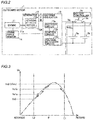
- the control circuit 13b continuously performs a retarding/advancing control until the output voltage value Va, which is a voltage value of DC power output from the rectifier circuit 13a, becomes equal to or higher than a first set voltage value Vs1 (Vs1a, Vs1b, or Vs1c), which is higher than a voltage value Vs0 at the start of the retarding/advancing control and is preset.
- Vs1a, Vs1b, or Vs1c a first set voltage value
- FIG. 3 shows an example of characteristics related to charging of the outboard motor 1 in which the horizontal axis represents the energization phase angle ⁇ and the vertical axis represents the output voltage value Va.
- the control circuit 13b sets a new first set voltage value Vs1b, which is higher than the first set voltage value Vs1, when the output voltage value Va becomes the first set voltage value Vs1a.
- the control circuit 13b continuously performs a retarding/advancing control until the output voltage value Va becomes equal to or higher than the first set voltage value Vs1b.
- the control circuit 13b sets a new first set voltage value Vs1c, which is higher than the first set voltage value Vs1b, when the output voltage value Va becomes the first set voltage value Vs1b.
- the control circuit 13b continuously performs a retarding/advancing control until the output voltage value Va becomes equal to or higher than the first set voltage value Vs1c.
- the first set voltage values Vs1a to Vs1c are simply described as a "first set voltage value Vs1" when they are not distinguished from each other.
- the control circuit 13b continuously performs a retarding/advancing control until the output voltage value Va becomes equal to or higher than a second set voltage value Vs2.
- the charge rated voltage values of the main battery 3a and the house battery 3b are set as the second set voltage value Vs2. That is, the control circuit 13b continuously performs a control to retard or advance the energization phase angle ⁇ until the output voltage value Va becomes equal to or higher than the charge rated voltage values of the main battery 3a and the house battery 3b.
- FIG. 3 shows an example in which the first set voltage value Vs1c is equal to the second set voltage value Vs2, but the first set voltage value Vs1c and the second set voltage value Vs2 may be different from each other.
- the control circuit 13b acquires information on the crank angle from the crank angle sensor 14.
- the crankshaft 11a and the rotor 12b are rotating in synchronization with each other, and thus the control circuit 13b performs a control to retard or advance the energization phase angle ⁇ , using the phase of the crank angle as the phase of the output voltage of the AC power generated by the generator 12.
- the rectifier circuit 13a acquires the phase of the output voltage of the AC power generated by the generator 12 based on the information (signal) on the crank angle. That is, the control circuit 13b performs a control to retard or advance the energization phase angle ⁇ with reference to the phase of the crank angle.
- the control circuit 13b performs a control to retard or advance the energization phase angle ⁇ a plurality of times by a unit angle ⁇ u until the output voltage value Va becomes equal to or higher than the first set voltage value Vs1.
- the amount of increase in the output voltage value Va is defined as Vu when the angle is retarded once by the unit angle ⁇ u.
- the detection resolution of the voltage value of the voltage detection circuit 13c is Vd larger than Vu, the voltage detection circuit 13c is not able to detect that the output voltage value Va is increased by Vu.
- the detection resolution refers to a minimum voltage width that is able to be detected by the voltage detection circuit 13c.
- the control circuit 13b continuously performs a control to retard the energization phase angle ⁇ the plurality of times by the unit angle ⁇ u until the output voltage value Va becomes equal to or higher than the set voltage value Vs.
- the output voltage value Va increases by as much as the plurality of times Vu (Vu x number of times) such that a voltage value obtained by multiplying Vu by the number of times the angle is retarded becomes larger than the detection resolution Vd.
- FIG. 4 shows an example in which the output voltage value Va is retarded four times by the unit angle ⁇ u to become the first set voltage value Vs1, but the present teaching is not limited to this example.
- the unit angle ⁇ u is an example of a "predetermined angle".
- the control circuit 13b performs one of retarding and advancing the energization phase angle ⁇ when the output voltage value Va is lower than the first set voltage value Vs1 (second set voltage value Vs2), and stops at least one of retarding or advancing the energization phase angle ⁇ based on the output voltage value Va becoming equal to or higher than the first set voltage value Vs1c and becoming equal to or higher than the second set voltage value Vs2.
- the control circuit 13b stops one of retarding and advancing the energization phase angle ⁇ and performs the other of retarding and advancing the energization phase angle ⁇ based on the output voltage value Va becoming equal to or higher than the first set voltage value Vs1c and becoming equal to or higher than the second set voltage value Vs2.
- the control circuit 13b when performing the other of retarding and advancing the energization phase angle ⁇ , performs a control to perform again one of retarding and advancing the energization phase angle ⁇ based on the output voltage value Va becoming less than the second set voltage value Vs2.
- the control circuit 13b first retards the energization phase angle ⁇ when the output voltage value Va is lower than the second set voltage value Vs2. For example, the energization phase angle ⁇ is retarded from a limit phase angle L2 described below. Then, the energization phase angle ⁇ is retarded such that the output voltage value Va increases to become equal to or higher than the second set voltage value Vs2. In such a case, as shown in FIG. 6 , the control circuit 13b stops retarding the energization phase angle ⁇ and advances the energization phase angle ⁇ . That is, the control circuit 13b inverts a direction in which the energization phase angle ⁇ is changed.
- the control circuit 13b stops advancing the energization phase angle ⁇ and retards the energization phase angle ⁇ again based on the output voltage value Va becoming lower than the second set voltage value Vs2. That is, the control circuit 13b repeatedly retards and advances the energization phase angle ⁇ based on the detected output voltage value Va such that the output voltage value Va approaches the second set voltage value Vs2.
- the output voltage value Va becomes a value near the second set voltage value Vs2.
- the control circuit 13b stops at least one of retarding or advancing the energization phase angle ⁇ when the output voltage value Va is lower than the first set voltage value Vs1, when one of retarding and advancing the energization phase angle ⁇ is performed, and when the energization phase angle ⁇ becomes a limit phase angle L1.
- the control circuit 13b stops one of retarding and advancing the energization phase angle ⁇ . Then, the control circuit 13b performs a control to perform the other of retarding and advancing the energization phase angle ⁇ .
- control circuit 13b performs a control to perform again one of retarding and advancing the energization phase angle ⁇ when the output voltage value Va is lower than the first set voltage value Vs1, when the other of retarding and advancing the energization phase angle ⁇ is performed, and when the energization phase angle ⁇ becomes the limit phase angle L2.
- the limit phase angle L2 is a value (more advanced value) different from the limit phase angle L1.
- the control circuit 13b when the output voltage value Va is lower than the first set voltage value Vs1, the control circuit 13b first retards the energization phase angle ⁇ . Then, the energization phase angle ⁇ is retarded such that the output voltage value Va changes, but the output voltage value Va may not become equal to or higher than the first set voltage value Vs1, as shown in FIG. 7 . In such a case, the control circuit 13b continues to retard the energization phase angle ⁇ . Then, when the energization phase angle ⁇ becomes the limit phase angle L1, the control circuit 13b stops retarding the energization phase angle ⁇ and advances the energization phase angle ⁇ .
- the control circuit 13b inverts a direction in which the energization phase angle ⁇ is changed when the energization phase angle ⁇ becomes the limit phase angle L1. Then, the energization phase angle ⁇ is advanced such that the output voltage value Va changes, but the control circuit 13b continues to advance the energization phase angle ⁇ when the output voltage value Va does not become equal to or higher than the first set voltage value Vs1. Then, when the energization phase angle ⁇ becomes the limit phase angle L2, the control circuit 13b stops advancing the energization phase angle ⁇ and retards the energization phase angle ⁇ again. Thus, when the output voltage value Va does not become equal to or higher than the first set voltage value Vs1, the energization phase angle ⁇ is repeatedly retarded and advanced within a range between the limit phase angle L1 and the limit phase angle L2.
- the control circuit 13b continuously performs a control to retard or advance the energization phase angle ⁇ before and after the number of batteries connected to the generator 12 is changed by the relay 3c (see FIG. 2 ) when the output voltage value Va is lower than the first set voltage value Vs1. For example, when the relay 3c is open, only the main battery 3a is connected to the generator 12, and when the relay 3c is closed, the main battery 3a and the house battery 3b are connected to the generator 12.
- FIG. 8 shows a flowchart of a control process of the outboard motor 1.
- step S1 the AC power generated by the generator is converted into DC power, and the converted DC power is supplied to a plurality of batteries. That is, charging of the plurality of batteries is started. Then, the process advances to step S2.
- step S2 the output voltage value Va, which is the voltage value of the DC power, is detected. Then, the process advances to step S3.
- step S3 it is determined whether or not the output voltage value Va is equal to or higher than the preset first set voltage value Vs1.
- the process advances to step S10, and when the output voltage value Va is lower than the first set voltage value Vs1, the process advances to step S4.
- step S4 one of retarding and advancing is performed.
- the energization phase angle ⁇ is retarded by the unit angle ⁇ u.
- the process advances to step S5. That is, according to preferred embodiments, the energization phase angle ⁇ is retarded until the output voltage value Va becomes equal to or higher than the first set voltage value Vs1.
- the energization phase angle ⁇ is retarded the plurality of times by the unit angle ⁇ u until the output voltage value Va becomes equal to or higher than the first set voltage value Vs1.
- step S5 it is determined whether or not the retarded energization phase angle ⁇ is the limit phase angle L1.
- the process returns to step S2, and when the retarded energization phase angle ⁇ is the limit phase angle L1, the process advances to step S6.
- step S6 the other of retarding and advancing is performed.
- the energization phase angle ⁇ is advanced by the unit angle ⁇ u. That is, when the output voltage value Va is lower than the first set voltage value Vs1, when the energization phase angle ⁇ is retarded, and when the energization phase angle ⁇ becomes the limit phase angle L1, retarding of the energization phase angle ⁇ is stopped, and the energization phase angle ⁇ is advanced. Then, the process advances to step S7.
- step S7 it is determined whether or not the advanced energization phase angle ⁇ is the limit phase angle L2.
- the process advances to step S8, and when the advanced energization phase angle ⁇ is the limit phase angle L2, the process returns to step S4.
- step S8 the output voltage value Va, which is the voltage value of the DC power, is detected. Then, the process advances to step S9.
- step S9 it is determined whether or not the output voltage value Va is equal to or higher than the first set voltage value Vs1.
- the process advances to step S15, and when the output voltage value Va is lower than the first set voltage value Vs1, the process returns to step S6.
- step S10 to which the process advances when the output voltage value Va becomes equal to or higher than the first set voltage value Vs1 in step S3, it is determined whether or not the output voltage value Va is equal to or higher than the second set voltage value Vs2.
- the process advances to step S12, and when the output voltage value Va is lower than the second set voltage value Vs2, the process advances to step S11.
- step S11 a new first set voltage value Vs1 is set. Then, the process advances to step S4.
- step S12 the other of retarding and advancing is performed.
- the energization phase angle ⁇ is advanced by the unit angle ⁇ u. Then, the process advances to step S13.
- step S13 the output voltage value Va, which is the voltage value of the DC power, is detected. Then, the process advances to step S14.
- step S14 it is determined whether or not the output voltage value Va is lower than the second set voltage value Vs2.
- the process advances to step S4. That is, when the energization phase angle ⁇ is advanced, the energization phase angle ⁇ is retarded based on the output voltage value Va becoming lower than the second set voltage value Vs2.
- the process returns to step S12.
- step S15 to which the process advances when the output voltage value Va becomes equal to or higher than the first set voltage value Vs1 in step S9, it is determined whether or not the output voltage value Va is equal to or higher than the second set voltage value Vs2.
- the process advances to step S17, and when the output voltage value Va is lower than the second set voltage value Vs2, the process advances to step S16.
- step S16 a new first set voltage value Vs1 is set. Then, the process advances to step S6.
- step S17 one of retarding and advancing is performed.
- the energization phase angle ⁇ is retarded by the unit angle ⁇ u. Then, the process advances to step S18.
- step S18 the output voltage value Va, which is the voltage value of the DC power, is detected. Then, the process advances to step S19.
- step S19 it is determined whether or not the output voltage value Va is lower than the second set voltage value Vs2.
- the process returns to step S6.
- the output voltage value Va is equal to or higher than the second set voltage value Vs2, the process returns to step S17.
- step S1 to step S19 when the output voltage value Va is lower than the first set voltage value Vs1, the energization phase angle ⁇ is continuously retarded or advanced before and after the number of batteries connected to the generator 12 is changed by the relay 3c. That is, when a state in which the house battery 3b is disconnected from the generator 12 is switched to a state in which the house battery 3b is energized by the relay 3c while the control process described above is being performed, and when a state in which the house battery 3b is energized is switched to a state in which the house battery 3b is disconnected from the generator 12 by the relay 3c while the control process described above is being performed, the operations in step S1 to step S19 described above are continuously performed.
- FIGS. 5 and 6 show an example in which the peak value Vp1 of the output voltage value Va exceeds the first set voltage value Vs1 when the retarding/advancing control is performed.
- FIG. 7 shows an example in which the peak value Vp2 of the output voltage value Va is lower than the first set voltage value Vs1 when the retarding/advancing control is performed.
- FIG. 9 shows an example in which two peak values (peaks) (Vp3 and Vp4) exist in the output voltage value Va when the retarding/advancing control is performed. It is assumed that Vp3 of the two peak values is lower than the first set voltage value Vs1, and Vp4 of the two peak values is equal to or higher than the first set voltage value Vs1.
- the energization phase angle ⁇ is continuously retarded until the output voltage value Va becomes equal to or higher than the first set voltage value Vs1c (second set voltage value Vs2). Then, as shown in FIG. 6 , the energization phase angle ⁇ is advanced when the output voltage value Va becomes equal to or higher than the second set voltage value Vs2. Then, the energization phase angle ⁇ is continuously retarded when the output voltage value Va becomes lower than the second set voltage value Vs2. Thus, the output voltage value Va is adjusted to a value near the second set voltage value Vs2.
- the energization phase angle ⁇ is retarded. Then, the energization phase angle ⁇ is advanced according to the energization phase angle ⁇ becoming the limit phase angle L1. Then, the energization phase angle ⁇ is retarded according to the energization phase angle ⁇ becoming the limit phase angle L2. Thus, the energization phase angle ⁇ is scanned so as to reciprocate between the limit phase angle L1 and the limit phase angle L2. Then, when the state of FIG. 7 changes to the state of FIG. 5, 6 , or 9 due to a change in the magnitude of the load in the outboard motor 1, the output voltage value Va is adjusted to a value near the second set voltage value Vs2.
- the energization phase angle ⁇ is continuously retarded until the energization phase angle ⁇ becomes equal to or higher than the first set voltage value Vs1. That is, the energization phase angle ⁇ is continuously retarded even above the peak value Vp3. Then, when the output voltage value Va becomes equal to or higher than the first set voltage value Vs1 (near the peak value Vp4), the energization phase angle ⁇ is advanced. Then, when the output voltage value Va becomes lower than the set voltage value Vs, the energization phase angle ⁇ is continuously retarded. Thus, the output voltage value Va is adjusted to a value near the set voltage value Vs (near the peak value Vp4).
- the control circuit 13b continuously performs the retarding/advancing control until the output voltage value Va becomes equal to or higher than the first set voltage value Vs1. Accordingly, the retarding/advancing control is continuously performed until the output voltage value Va becomes equal to or higher than the first set voltage value Vs1, and thus stopping the retarding/advancing control before the output voltage value Va becomes equal to or higher than the first set voltage value Vs1 is significantly reduced or prevented. Therefore, when power is supplied to the main battery 3a and the house battery 3b, the retarding/advancing control is continuously performed even when the amount of increase in the output voltage value Va before and after the retarding/advancing control is smaller than the detection resolution Vd of the output voltage value Va.
- the retarding/advancing control is continuously performed. Consequently, as compared with a case in which the retarding/advancing control is terminated before the output voltage value Va becomes equal to or higher than the first set voltage value Vs1Vs, the main battery 3a and the house battery 3b are efficiently charged even when power is supplied from the generator 12 to the main battery 3a and the house battery 3b.
- the control circuit 13b performs a control to retard or advance the energization phase angle ⁇ a plurality of times by the unit angle ⁇ u until the output voltage value Va becomes equal to or higher than the first set voltage value Vs1. Accordingly, when the energization phase angle ⁇ is retarded or advanced by the unit angle ⁇ u, the energization phase angle ⁇ is retarded or advanced the plurality of times without terminating the retarding/advancing control before the output voltage value Va becomes equal to or higher than the first set voltage value Vs1 even when the amount of change in the output voltage value Va is relatively small.
- the change in the output voltage value Va is relatively small such that the main battery 3a and the house battery 3b are efficiently charged as compared with a case in which the retarding/advancing control is terminated. Furthermore, even when the amount of change in the output voltage value Va is relatively small, the retarding/advancing control is not terminated, and thus the unit angle ⁇ u is set to a relatively small value. Consequently, the energization phase angle ⁇ is finely adjusted, and thus the energization phase angle ⁇ is more accurately adjusted to an optimum value.
- the control circuit 13b performs a control to perform one of retarding and advancing the energization phase angle ⁇ when the output voltage value Va is lower than the first set voltage value Vs1, and to stop at least one of retarding or advancing the energization phase angle ⁇ based on the output voltage value Va becoming equal to or higher than the first set voltage value Vs1 and becoming equal to or higher than the preset second set voltage value Vs2. Accordingly, at least one of retarding or advancing the energization phase angle ⁇ is stopped based on the output voltage value Va becoming equal to or higher than the second set voltage value Vs2, and thus a decrease in the charging efficiency due to a decrease in the output voltage value Va is significantly reduced or prevented. Furthermore, an unnecessary increase in the output voltage value Va is significantly reduced or prevented.
- the control circuit 13b performs one of retarding and advancing the energization phase angle ⁇ when the output voltage value Va is lower than the first set voltage value Vs1, and performs the other of retarding and advancing the energization phase angle ⁇ based on the output voltage value Va becoming equal to or higher than the first set voltage value Vs1 and becoming equal to or higher than the preset second set voltage value Vs2. Accordingly, when the output voltage value Va becomes equal to or higher than the second set voltage value Vs2, the direction in which the energization phase angle ⁇ is changed is inverted. Consequently, even when the output voltage value Va increases more than necessary, the direction in which the energization phase angle ⁇ is changed is inverted such that the output voltage value Va is closer to an appropriate value (second set voltage value Vs2).
- the control circuit 13b performs a control to perform again one of retarding and advancing the energization phase angle ⁇ based on the output voltage value Va becoming lower than the second set voltage value Vs2 when performing the other of retarding and advancing the energization phase angle ⁇ . Accordingly, when the other of retarding and advancing the energization phase angle ⁇ is performed, the output voltage value Va is again increased to the second set voltage value Vs2 or higher even when the output voltage value Va becomes lower than the second set voltage value Vs2. Consequently, the output voltage value Va is maintained at a value near the second set voltage value Vs2.
- the second set voltage value Vs2 is the charge rated voltage values of the main battery 3a and the house battery 3b. Accordingly, the charge rated voltage values of the main battery 3a and the house battery 3b are set as the second set voltage value Vs2 such that a control is continuously performed to retard or advance the energization phase angle ⁇ until the output voltage value Va becomes equal to or higher than the charge rated voltage values of the main battery 3a and the house battery 3b. Consequently, the output voltage value Va is more reliably set to the charge rated voltage values or higher of the main battery 3a and the house battery 3b. Thus, the main battery 3a and the house battery 3b are charged with a more appropriate voltage value.
- the control circuit 13b performs a control to stop retarding the energization phase angle ⁇ when the output voltage value Va is lower than the first set voltage value Vs1, when the energization phase angle ⁇ is retarded, and when the energization phase angle ⁇ becomes the limit phase angle L1. Accordingly, when the energization phase angle ⁇ is retarded, retarding of the energization phase angle ⁇ beyond the limit phase angle L1 is significantly reduced or prevented even when the output voltage value Va does not become equal to or higher than the first set voltage value Vs1.
- the retarding/advancing control is performed such that excessive retarding is significantly reduced or prevented even when the output voltage value Va does not become equal to or higher than the first set voltage value Vs1.
- a decrease in the charging efficiency due to a decrease in the output voltage value Va caused by excessive retarding is significantly reduced or prevented.
- the control circuit 13b performs a control to stop retarding the energization phase angle ⁇ and advance the energization phase angle ⁇ when the output voltage value Va is lower than the first set voltage value Vs1, when the energization phase angle ⁇ is retarded, and when the energization phase angle ⁇ becomes the limit phase angle L1. Accordingly, when the energization phase angle ⁇ is retarded, the energization phase angle ⁇ is advanced with the limit phase angle L1 as a turnaround point even when the output voltage value Va does not become equal to or higher than the first set voltage value Vs1. Consequently, the energization phase angle ⁇ is continuously changed while retarding of the energization phase angle ⁇ beyond the limit phase angle L1 is significantly reduced or prevented such that an energization phase angle ⁇ for better charging efficiency is found.
- the control circuit 13b performs a control to retard the energization phase angle ⁇ again when the output voltage value Va is lower than the first set voltage value Vs1, when the energization phase angle ⁇ is advanced, and when the energization phase angle ⁇ becomes the limit phase angle L2. Accordingly, even when the energization phase angle ⁇ is advanced, a change in the energization phase angle ⁇ beyond the limit phase angle L2 is significantly reduced or prevented.
- the energization phase angle ⁇ is advanced, the energization phase angle ⁇ is retarded again when the output voltage value Va does not become equal to or higher than the first set voltage value Vs1, and thus an energization phase angle ⁇ for better charging efficiency is continuously found.
- the outboard motor 1 includes the relay 3c provided between the generator 12 and at least one of the main battery 3a or the house battery 3b to switch between a state in which at least one of the main battery 3a or the house battery 3b is connected to the generator 12 and a state in which at least one of the main battery 3a or the house battery 3b is disconnected from the generator 12. Furthermore, the control circuit 13b continuously performs a control to retard or advance the energization phase angle ⁇ before and after the number of batteries connected to the generator 12 is changed by the relay 3c when the output voltage value Va is lower than the first set voltage value Vs1.
- the energization phase angle ⁇ is continuously retarded or advanced, and thus the main battery 3a and the house battery 3b are efficiently charged regardless of a change in the number of batteries.
- the main battery 3a and the house battery 3b are efficiently charged, similarly to the structure of the outboard motor 1.
- the engine is preferably used as a drive engine in the preferred embodiments described above, the present teaching is not restricted to this.
- the drive engine an electric motor that generates a driving force with power may alternatively be used, or a hybrid system obtained by combining an engine and an electric motor may alternatively be used.
- phase of the output voltage of the generated AC power is preferably acquired based on the information (signal) on the crank angle detected by the crank angle sensor in the preferred embodiments described above, the present teaching is not restricted to this.
- the phase of the output voltage of the generated AC power may alternatively be acquired based on a signal detected by a rotation angle sensor that detects the rotation angle of the rotor of the generator.
- batteries the main battery and the house battery
- the present teaching is not restricted to this.
- three or more batteries may alternatively be provided.
- main battery and house battery are preferably provided in the hull in the preferred embodiments described above, the present teaching is not restricted to this.
- at least one of the main battery or the house battery may alternatively be provided in the outboard.
- the energization phase angle is preferably first retarded and then advanced in the preferred embodiments described above, the present teaching is not restricted to this. That is, the energization phase angle may alternatively be first advanced and then retarded.
- the energization phase angle is preferably retarded (advanced) a plurality of times by the unit angle until the output voltage value becomes equal to or higher than the first set voltage value in the preferred embodiments described above, the present teaching is not restricted to this. That is, the energization phase angle may alternatively be retarded or advanced only once such that the output voltage value becomes equal to or higher than the first set voltage value.
- the energization phase angle is preferably advanced based on the output voltage value becoming equal to or higher than the second set voltage value when the energization phase angle is retarded in the preferred embodiments described above, the present teaching is not restricted to this.
- the energization phase angle may alternatively be fixed to an angle at which the output voltage value becomes equal to or higher than the second set voltage value based on the output voltage value becoming equal to or higher than the second set voltage value. That is, both advancing and retarding may be stopped based on the output voltage value becoming equal to or higher than the second set voltage value.
- the present teaching is not restricted to this.
- the energization phase angle may alternatively be continuously retarded or advanced without providing at least one of the two limit phase angles.
- the energization phase angle is preferably advanced (retarded) based on the energization phase angle becoming the limit phase angle when the energization phase angle is retarded (advanced) in the preferred embodiments described above, the present teaching is not restricted to this.
- the energization phase angle may alternatively be fixed to the limit phase angle when the energization phase angle is retarded (advanced). That is, both advancing and retarding may be stopped based on the energization phase angle becoming the limit phase angle.
- the relay is preferably provided in the outboard motor in the preferred embodiments described above, the present teaching is not restricted to this.
- the main battery and the house battery may alternatively be constantly connected to the generator without providing the relay in the outboard motor.
- the second set voltage value is preferably set to the charge rated voltage values of the main battery and the house battery in the preferred embodiments described above, the present teaching is not restricted to this. That is, the second set voltage value may alternatively be set to a value other than the charge rated voltage values of the main battery and the house battery.
- the battery controller and the relay are preferably provided in the outboard motor in the preferred embodiments described above, the present teaching is not restricted to this.
- the battery controller and the relay may alternatively be provided in the hull.
Landscapes
- Engineering & Computer Science (AREA)
- Mechanical Engineering (AREA)
- Power Engineering (AREA)
- Chemical & Material Sciences (AREA)
- Combustion & Propulsion (AREA)
- Ocean & Marine Engineering (AREA)
- Transportation (AREA)
- Control Of Eletrric Generators (AREA)
- Control Of Charge By Means Of Generators (AREA)
Abstract
Description
- The present invention relates to an outboard motor including a generator and a control method for an outboard motor.
- An outboard motor including a generator and a control method for an outboard motor are known in general. Such an outboard motor is disclosed in
JP 5367382 B2 -
JP 5367382 B2 - A method for retarding control in a battery charger connected between an AC generator and a battery is known in general. Such a method for retarding control is disclosed in
JP 4990883 B2 -
JP 4990883 B2 - The retarding control method described in
JP 4990883 B2 JP 5367382 B2 JP 5367382 B2 5367382 4990883 4990883 - It is an object of the present invention to provide an outboard motor and a control method for an outboard motor that each efficiently charge a plurality of batteries even when power is supplied from a generator to the plurality of batteries. According to the present invention, said object is solved by an outboard motor and a control method for an outboard motor having the features of
independent claims - An outboard motor according to a preferred embodiment includes a drive engine, a generator configured to generate power by operation of the drive engine, a power converter configured to convert AC power generated by the generator into DC power, the power converter being configured to supply converted DC power to a plurality of batteries, a voltage detector configured to detect a voltage value of the DC power converted by the power converter, and a phase angle controller configured or programmed to perform a retarding/advancing control to retard or advance an energization phase angle, which is an energization timing with respect to a phase of an output voltage of the AC power generated by the generator. The phase angle controller is configured or programmed to continuously perform the retarding/advancing control until the voltage value of the DC power becomes equal to or higher than a first set voltage value, which is higher than a voltage value at a start of the retarding/advancing control and is preset.
- In an outboard motor according to a preferred embodiment, the phase angle controller is configured or programmed to continuously perform the retarding/advancing control until the voltage value of the DC power becomes equal to or higher than the first set voltage value, which is higher than the voltage value at the start of the retarding/advancing control and is preset. Accordingly, the retarding/advancing control is continuously performed until the voltage value of the DC power becomes equal to or higher than the first set voltage value, and thus stopping the retarding/advancing control before the voltage value of the DC power becomes equal to or higher than the first set voltage value is significantly reduced or prevented. Therefore, when power is supplied to the plurality of batteries, the retarding/advancing control is continuously performed even when the amount of increase in the voltage value of the DC power before and after the retarding/advancing control is smaller than the detection resolution of the voltage value of the DC power. That is, even when it is not detected that the voltage value (power generation amount) of the DC power has increased (the voltage value of the DC power detected this time is higher than the voltage value of the DC power detected last time), the retarding/advancing control is continuously performed. Consequently, as compared with a case in which the retarding/advancing control is terminated before the voltage value of the DC power becomes equal to or higher than the first set voltage value, the plurality of batteries are efficiently charged even when power is supplied from the generator to the plurality of batteries.
- In an outboard motor according to a preferred embodiment, the phase angle controller is preferably configured or programmed to perform a control to retard or advance the energization phase angle a plurality of times by a predetermined angle until the voltage value of the DC power becomes equal to or higher than the first set voltage value. Accordingly, when the energization phase angle is retarded or advanced by the predetermined angle, the energization phase angle is retarded or advanced the plurality of times without terminating the retarding/advancing control before the voltage value of the DC power becomes equal to or higher than the first set voltage value even when the amount of change in the voltage value of the DC power is relatively small. Consequently, the change in the voltage value of the DC power is relatively small such that the plurality of batteries are efficiently charged as compared with a case in which the retarding/advancing control is terminated. Furthermore, even when the amount of change in the voltage value of the DC power is relatively small, the retarding/advancing control is not terminated, and thus the predetermined angle is set to a relatively small value. Consequently, the energization phase angle is finely adjusted, and thus the energization phase angle is more accurately adjusted to an optimum value.
- In an outboard motor according to a preferred embodiment, the phase angle controller is preferably configured or programmed to perform a control to perform one of retarding and advancing the energization phase angle when the voltage value of the DC power is lower than the first set voltage value, and stop at least one of retarding or advancing the energization phase angle based on the voltage value of the DC power becoming equal to or higher than the first set voltage value and becoming equal to or higher than a preset second set voltage value. When one of continuously retarding and advancing an energization phase angle is performed even after the voltage value of DC power becomes equal to or higher than a second set voltage value, the charging efficiency may decrease due to a decrease in the voltage value of the DC power, or the voltage value of the DC power may increase more than necessary. In this regard, according to a preferred embodiment, the at least one of retarding or advancing the energization phase angle is stopped based on the voltage value of the DC power becoming equal to or higher than the second set voltage value, and thus a decrease in the charging efficiency due to a decrease in the voltage value of the DC power is significantly reduced or prevented. Furthermore, an unnecessary increase in the voltage value of the DC power is significantly reduced or prevented.
- In an outboard motor according to a preferred embodiment, the phase angle controller is preferably configured or programmed to perform one of retarding and advancing the energization phase angle when the voltage value of the DC power is lower than the first set voltage value, and to perform the other of retarding and advancing the energization phase angle based on the voltage value of the DC power becoming equal to or higher than the first set voltage value and becoming equal to or higher than a preset second set voltage value. Accordingly, when the voltage value of the DC power becomes equal to or higher than the second set voltage value, a direction in which the energization phase angle is changed is inverted. Consequently, even when the voltage value of the DC power increases more than necessary, the direction in which the energization phase angle is changed is inverted such that the voltage value of the DC power is closer to an appropriate value (second set voltage value).
- In an outboard motor that performs the other of retarding and advancing the energization phase angle based on the voltage value of the DC power becoming equal to or higher than the second set voltage value, the phase angle controller is preferably configured or programmed to perform a control to perform again the one of retarding and advancing the energization phase angle based on the voltage value of the DC power becoming lower than the second set voltage value when performing the other of retarding and advancing the energization phase angle. Accordingly, when the other of retarding and advancing the energization phase angle is performed, the voltage value of the DC power is again increased to the second set voltage value or higher even when the voltage value of the DC power becomes lower than the second set voltage value. Consequently, the voltage value of the DC power is maintained at a value near the second set voltage value.
- In an outboard motor that stops the at least one of retarding or advancing the energization phase angle based on the voltage value of the DC power becoming equal to or higher than the second set voltage value, the second set voltage value is preferably charge rated voltage values of the plurality of batteries. Accordingly, the charge rated voltage values of the plurality of batteries are set as the second set voltage value such that a control is continuously performed to retard or advance the energization phase angle until the voltage value of the DC power becomes equal to or higher than the charge rated voltage values of the plurality of batteries. Consequently, the voltage value of the DC power is more reliably set to the charge rated voltage values or higher of the plurality of batteries. Thus, the plurality of batteries are charged with a more appropriate voltage value.
- In an outboard motor according to a preferred embodiment, the phase angle controller is preferably configured or programmed to perform a control to stop at least one of retarding or advancing the energization phase angle when the voltage value of the DC power is lower than the first set voltage value, when one of retarding and advancing the energization phase angle is performed, and when the energization phase angle becomes a first limit phase angle. Accordingly, when the one of retarding and advancing the energization phase angle is performed, retarding or advancing of the energization phase angle beyond the first limit phase angle is significantly reduced or prevented even when the voltage value of the DC power does not become equal to or higher than the first set voltage value. Consequently, the retarding/advancing control is performed such that excessive retarding or advancing is significantly reduced or prevented even when the voltage value of the DC power does not become equal to or higher than the first set voltage value. Thus, a decrease in the charging efficiency due to a decrease in the voltage value of the DC power caused by excessive retarding or advancing is significantly reduced or prevented.
- In an outboard motor according to a preferred embodiment, the phase angle controller is preferably configured or programmed to perform a control to stop one of retarding and advancing the energization phase angle and perform the other of retarding and advancing the energization phase angle when the voltage value of the DC power is lower than the first set voltage value, when the one of retarding and advancing the energization phase angle is performed, and when the energization phase angle becomes a first limit phase angle. Accordingly, when the one of retarding and advancing the energization phase angle is performed, the other of retarding and advancing the energization phase angle is performed with the first limit phase angle as a turnaround point even when the voltage value of the DC power does not become equal to or higher than the first set voltage value. Consequently, the energization phase angle is continuously changed while retarding or advancing of the energization phase angle beyond the first limit phase angle is significantly reduced or prevented such that an energization phase angle for better charging efficiency is found.
- In an outboard motor that stops the one of retarding and advancing the energization phase angle and performs the other of retarding and advancing the energization phase angle when the energization phase angle becomes the first limit phase angle, the phase angle controller is preferably configured or programmed to perform a control to perform again the one of retarding and advancing the energization phase angle when the voltage value of the DC power is lower than the first set voltage value, when the other of retarding and advancing the energization phase angle is performed, and when the energization phase angle becomes a second limit phase angle. Accordingly, even when the other of retarding and advancing the energization phase angle is performed, a change in the energization phase angle beyond the second limit phase angle is significantly reduced or prevented. Furthermore, even when the other of retarding and advancing the energization phase angle is performed, the one of retarding and advancing the energization phase angle is performed again when the voltage value of the DC power does not become equal to or higher than the first set voltage value, and thus an energization phase angle for better charging efficiency is continuously found.
- An outboard motor according to a preferred embodiment preferably further includes a relay provided between the generator and at least one of the plurality of batteries and configured to switch between a state in which the at least one of the plurality of batteries is connected to the generator and a state in which the at least one of the plurality of batteries is disconnected from the generator, and the phase angle controller is preferably configured or programmed to continuously perform a control to retard or advance the energization phase angle before and after a number of the batteries connected to the generator is changed by the relay when the voltage value of the DC power is lower than the first set voltage value. Accordingly, even when the number of the batteries connected to the generator is changed by the operation of the relay, the energization phase angle is continuously retarded or advanced, and thus the plurality of batteries are efficiently charged regardless of a change in the number of the batteries.
- A control method for an outboard motor including a generator configured to generate power by operation of a drive engine according to a preferred embodiment includes converting AC power generated by the generator into DC power and supplying converted DC power to a plurality of batteries, detecting a voltage value of the DC power, and performing a retarding/advancing control to retard or advance an energization phase angle, which is an energization timing with respect to a phase of an output voltage of the AC power generated by the generator. The performing of the retarding/advancing control includes continuously performing the retarding/advancing control until the voltage value of the DC power becomes equal to or higher than a first set voltage value, which is higher than a voltage value at a start of the retarding/advancing control and is preset.
- In a control method for an outboard motor according to a preferred embodiment, similarly to the outboard motor according to preferred embodiments described above, even when power is supplied from the generator to the plurality of batteries, the plurality of batteries are efficiently charged.
- In a control method for an outboard motor according to a preferred embodiment, the performing of the retarding/advancing control preferably includes retarding or advancing the energization phase angle a plurality of times by a predetermined angle until the voltage value of the DC power becomes equal to or higher than the first set voltage value. Accordingly, when the energization phase angle is retarded or advanced by the predetermined angle, the energization phase angle is retarded or advanced the plurality of times without terminating the retarding/advancing control before the voltage value of the DC power becomes equal to or higher than the first set voltage value even when the amount of change in the voltage value of the DC power is relatively small. Consequently, the change in the voltage value of the DC power is relatively small such that the plurality of batteries are efficiently charged as compared with a case in which the retarding/advancing control is terminated. Furthermore, even when the amount of change in the voltage value of the DC power is relatively small, the retarding/advancing control is not terminated, and thus the predetermined angle is set to a relatively small value. Consequently, the energization phase angle is finely adjusted, and thus the energization phase angle is more accurately adjusted to an optimum value.
- In a control method for an outboard motor according to a preferred embodiment, the performing of the retarding/advancing control preferably includes performing one of retarding and advancing the energization phase angle when the voltage value of the DC power is lower than the first set voltage value, and stopping at least one of retarding or advancing the energization phase angle based on the voltage value of the DC power becoming equal to or higher than the first set voltage value and becoming equal to or higher than a preset second set voltage value. Accordingly, the at least one of retarding or advancing the energization phase angle is stopped based on the voltage value of the DC power becoming equal to or higher than the second set voltage value, and thus a decrease in the charging efficiency due to a decrease in the voltage value of the DC power is significantly reduced or prevented. Furthermore, an unnecessary increase in the voltage value of the DC power is significantly reduced or prevented.
- In a control method for an outboard motor according to a preferred embodiment, the performing of the retarding/advancing control preferably includes performing one of retarding and advancing the energization phase angle when the voltage value of the DC power is lower than the first set voltage value, and performing the other of retarding and advancing the energization phase angle based on the voltage value of the DC power becoming equal to or higher than the first set voltage value and becoming equal to or higher than a preset second set voltage value. Accordingly, when the voltage value of the DC power becomes equal to or higher than the second set voltage value, a direction in which the energization phase angle is changed is inverted. Consequently, even when the voltage value of the DC power increases more than necessary, the direction in which the energization phase angle is changed is inverted such that the voltage value of the DC power is closer to an appropriate value (second set voltage value).
- In such a case, the performing of the retarding/advancing control preferably includes performing a control to perform again the one of retarding and advancing the energization phase angle based on the voltage value of the DC power becoming lower than the second set voltage value when the other of retarding and advancing the energization phase angle is performed. Accordingly, when the other of retarding and advancing the energization phase angle is performed, the voltage value of the DC power is again increased to the second set voltage value or higher even when the voltage value of the DC power becomes lower than the second set voltage value. Consequently, the voltage value of the DC power is maintained at a value near the second set voltage value.
- The above and other elements, features, steps, characteristics and advantages of preferred embodiments will become more apparent from the following detailed description of the preferred embodiments with reference to the attached drawings.
-
-
FIG. 1 is a perspective view schematically showing an outboard motor boat including an outboard motor according to a preferred embodiment. -
FIG. 2 is a block diagram illustrating the structure of an outboard motor, a main battery, and a house battery according to a preferred embodiment. -
FIG. 3 is a diagram illustrating a retarding/advancing control according to a preferred embodiment. -
FIG. 4 is a diagram illustrating the relationship between a unit angle and detection resolution according to a preferred embodiment. -
FIG. 5 is a diagram illustrating retarding an energization phase angle according to a preferred embodiment. -
FIG. 6 is a diagram illustrating a retarding/advancing control when an output voltage value is less than a set voltage value and a retarding/advancing control when the output voltage value is equal to or higher than the set voltage value according to a preferred embodiment. -
FIG. 7 is a diagram illustrating a limit phase angle according to a preferred embodiment. -
FIG. 8 is a flowchart showing a control process of an outboard motor according to a preferred embodiment. -
FIG. 9 is a diagram illustrating an example of a retarding/advancing control when there are two peak values in an output voltage value according to a preferred embodiment. - Preferred embodiments are hereinafter described with reference to the drawings.
- The structure of an
outboard motor boat 100 according to preferred embodiments is now described with reference toFIGS. 1 to 7 . In the figures, arrow FWD represents the forward movement direction of theoutboard motor boat 100, and arrow BWD represents the reverse movement direction of theoutboard motor boat 100. Theoutboard motor boat 100 is an example of a "marine vessel". - As shown in
FIG. 1 , theoutboard motor boat 100 includes anoutboard motor 1, ahull 2, amain battery 3a, and ahouse battery 3b. Oneoutboard motor 1 is provided on the rear of thehull 2, for example. Themain battery 3a and thehouse battery 3b are examples of a "battery". - As shown in
FIG. 2 , theoutboard motor 1 includes anengine 11, agenerator 12, a rectifier regulator 13 (hereinafter referred to as a "RECT/REG 13"), and acrank angle sensor 14. Theengine 11 is an example of a "drive engine". - The
engine 11 is an internal combustion engine, and generates a driving force by burning fuel. Theengine 11 rotates acrankshaft 11a with the generated driving force to rotate a propeller of theoutboard motor 1. A propulsive force is generated by the rotation of the propeller, and thehull 2 moves. Theengine 11 includes a starter motor (not shown). The starter motor of theengine 11 is driven with power supplied from themain battery 3a such that thecrankshaft 11a is rotated, and theengine 11 is started. - The
engine 11 operates such that thegenerator 12 generates power. Specifically, thegenerator 12 includes astator 12a and arotor 12b. Thestator 12a includes a coil connected to the RECT/REG 13, for example. Therotor 12b includes a permanent magnet. Thecrankshaft 11a of theengine 11 is rotated such that therotor 12b rotates with respect to thestator 12a, and an electromotive force is generated. Thegenerator 12 supplies generated AC power to the RECT/REG 13. For example, thegenerator 12 generates three-phase (U-phase, V-phase, and W-phase) AC power by rotation of therotor 12b. Therotor 12b also defines and functions as a flywheel for thecrankshaft 11a. - The RECT/
REG 13 converts the AC power generated by thegenerator 12 into DC power and adjusts the output voltage value Va of the converted DC power. Specifically, the RECT/REG 13 includes arectifier circuit 13a, acontrol circuit 13b, and avoltage detection circuit 13c. Therectifier circuit 13a is an example of a "power converter". Thecontrol circuit 13b is an example of a "phase angle controller". - The
rectifier circuit 13a converts (rectifies) the AC power generated by thegenerator 12 into DC power and supplies the converted (rectified) DC power to each of themain battery 3a and thehouse battery 3b. Specifically, therectifier circuit 13a includes a plurality of switching elements. The three-phase AC power output from thegenerator 12 is converted into DC power by switching (repetition of energization and de-energization) of the plurality of switching elements. - The
control circuit 13b includes a central processing unit (CPU), for example. The CPU executes a program such that thecontrol circuit 13b performs each control process. Thecontrol circuit 13b performs a control (retarding/advancing control) to retard or advance an energization phase angle θ, which is the energization timing with respect to the phase of the output voltage of the AC power generated by thegenerator 12, as described below. - The
voltage detection circuit 13c detects the output voltage value Va of the DC power converted by therectifier circuit 13a. Thevoltage detection circuit 13c transmits the detected output voltage value Va to thecontrol circuit 13b. - The
crank angle sensor 14 detects the rotation angle (crank angle) of thecrankshaft 11a of theengine 11. Thecrank angle sensor 14 transmits information (signal) on the detected crank angle to thecontrol circuit 13b of the RECT/REG 13. - The
main battery 3a supplies power to an engine auxiliary load group (not shown) and the starter motor via cables, for example. Thehouse battery 3b supplies power to an onboard electrical equipment load group (not shown) via a cable, for example. - The
outboard motor 1 is placed between thegenerator 12 and thehouse battery 3b, and includes arelay 3c to switch between a state in which thehouse battery 3b is connected to thegenerator 12 and a state in which thehouse battery 3b is disconnected from thegenerator 12. Theoutboard motor 1 includes abattery controller 3d configured or programmed to control therelay 3c to change the number of batteries connected to thegenerator 12. Thebattery controller 3d is configured or programmed to perform a control to switch between a state in which thehouse battery 3b is connected to thegenerator 12 and a state in which thehouse battery 3b is disconnected from thegenerator 12 by operating therelay 3c. - According to preferred embodiments, as shown in
FIG. 3 , thecontrol circuit 13b continuously performs a retarding/advancing control until the output voltage value Va, which is a voltage value of DC power output from therectifier circuit 13a, becomes equal to or higher than a first set voltage value Vs1 (Vs1a, Vs1b, or Vs1c), which is higher than a voltage value Vs0 at the start of the retarding/advancing control and is preset. Note thatFIG. 3 shows an example of characteristics related to charging of theoutboard motor 1 in which the horizontal axis represents the energization phase angle θ and the vertical axis represents the output voltage value Va. For example, thecontrol circuit 13b sets a new first set voltage value Vs1b, which is higher than the first set voltage value Vs1, when the output voltage value Va becomes the first set voltage value Vs1a. Thecontrol circuit 13b continuously performs a retarding/advancing control until the output voltage value Va becomes equal to or higher than the first set voltage value Vs1b. Furthermore, thecontrol circuit 13b sets a new first set voltage value Vs1c, which is higher than the first set voltage value Vs1b, when the output voltage value Va becomes the first set voltage value Vs1b. Thecontrol circuit 13b continuously performs a retarding/advancing control until the output voltage value Va becomes equal to or higher than the first set voltage value Vs1c. According to preferred embodiments, the first set voltage values Vs1a to Vs1c are simply described as a "first set voltage value Vs1" when they are not distinguished from each other. - The
control circuit 13b continuously performs a retarding/advancing control until the output voltage value Va becomes equal to or higher than a second set voltage value Vs2. According to preferred embodiments, the charge rated voltage values of themain battery 3a and thehouse battery 3b are set as the second set voltage value Vs2. That is, thecontrol circuit 13b continuously performs a control to retard or advance the energization phase angle θ until the output voltage value Va becomes equal to or higher than the charge rated voltage values of themain battery 3a and thehouse battery 3b.FIG. 3 shows an example in which the first set voltage value Vs1c is equal to the second set voltage value Vs2, but the first set voltage value Vs1c and the second set voltage value Vs2 may be different from each other. - Specifically, the
control circuit 13b acquires information on the crank angle from thecrank angle sensor 14. Thecrankshaft 11a and therotor 12b are rotating in synchronization with each other, and thus thecontrol circuit 13b performs a control to retard or advance the energization phase angle θ, using the phase of the crank angle as the phase of the output voltage of the AC power generated by thegenerator 12. Therectifier circuit 13a acquires the phase of the output voltage of the AC power generated by thegenerator 12 based on the information (signal) on the crank angle. That is, thecontrol circuit 13b performs a control to retard or advance the energization phase angle θ with reference to the phase of the crank angle. - As shown in
FIG. 4 , thecontrol circuit 13b performs a control to retard or advance the energization phase angle θ a plurality of times by a unit angle θu until the output voltage value Va becomes equal to or higher than the first set voltage value Vs1. The amount of increase in the output voltage value Va is defined as Vu when the angle is retarded once by the unit angle θu. In such a case, when the detection resolution of the voltage value of thevoltage detection circuit 13c is Vd larger than Vu, thevoltage detection circuit 13c is not able to detect that the output voltage value Va is increased by Vu. The detection resolution refers to a minimum voltage width that is able to be detected by thevoltage detection circuit 13c. Therefore, according to preferred embodiments, thecontrol circuit 13b continuously performs a control to retard the energization phase angle θ the plurality of times by the unit angle θu until the output voltage value Va becomes equal to or higher than the set voltage value Vs. Thus, the output voltage value Va increases by as much as the plurality of times Vu (Vu x number of times) such that a voltage value obtained by multiplying Vu by the number of times the angle is retarded becomes larger than the detection resolution Vd. Note thatFIG. 4 shows an example in which the output voltage value Va is retarded four times by the unit angle θu to become the first set voltage value Vs1, but the present teaching is not limited to this example. The unit angle θu is an example of a "predetermined angle". - As shown in
FIG. 5 , according to preferred embodiments, thecontrol circuit 13b performs one of retarding and advancing the energization phase angle θ when the output voltage value Va is lower than the first set voltage value Vs1 (second set voltage value Vs2), and stops at least one of retarding or advancing the energization phase angle θ based on the output voltage value Va becoming equal to or higher than the first set voltage value Vs1c and becoming equal to or higher than the second set voltage value Vs2. According to preferred embodiments, thecontrol circuit 13b stops one of retarding and advancing the energization phase angle θ and performs the other of retarding and advancing the energization phase angle θ based on the output voltage value Va becoming equal to or higher than the first set voltage value Vs1c and becoming equal to or higher than the second set voltage value Vs2. As shown inFIG. 6 , when performing the other of retarding and advancing the energization phase angle θ, thecontrol circuit 13b performs a control to perform again one of retarding and advancing the energization phase angle θ based on the output voltage value Va becoming less than the second set voltage value Vs2. - Specifically, as shown in
FIG. 5 , thecontrol circuit 13b first retards the energization phase angle θ when the output voltage value Va is lower than the second set voltage value Vs2. For example, the energization phase angle θ is retarded from a limit phase angle L2 described below. Then, the energization phase angle θ is retarded such that the output voltage value Va increases to become equal to or higher than the second set voltage value Vs2. In such a case, as shown inFIG. 6 , thecontrol circuit 13b stops retarding the energization phase angle θ and advances the energization phase angle θ. That is, thecontrol circuit 13b inverts a direction in which the energization phase angle θ is changed. Thus, the output voltage value Va decreases. Then, thecontrol circuit 13b stops advancing the energization phase angle θ and retards the energization phase angle θ again based on the output voltage value Va becoming lower than the second set voltage value Vs2. That is, thecontrol circuit 13b repeatedly retards and advances the energization phase angle θ based on the detected output voltage value Va such that the output voltage value Va approaches the second set voltage value Vs2. Thus, the output voltage value Va becomes a value near the second set voltage value Vs2. - As shown in
FIG. 7 , thecontrol circuit 13b stops at least one of retarding or advancing the energization phase angle θ when the output voltage value Va is lower than the first set voltage value Vs1, when one of retarding and advancing the energization phase angle θ is performed, and when the energization phase angle θ becomes a limit phase angle L1. According to preferred embodiments, thecontrol circuit 13b stops one of retarding and advancing the energization phase angle θ. Then, thecontrol circuit 13b performs a control to perform the other of retarding and advancing the energization phase angle θ. Furthermore, thecontrol circuit 13b performs a control to perform again one of retarding and advancing the energization phase angle θ when the output voltage value Va is lower than the first set voltage value Vs1, when the other of retarding and advancing the energization phase angle θ is performed, and when the energization phase angle θ becomes the limit phase angle L2. The limit phase angle L2 is a value (more advanced value) different from the limit phase angle L1. - For example, when the output voltage value Va is lower than the first set voltage value Vs1, the
control circuit 13b first retards the energization phase angle θ. Then, the energization phase angle θ is retarded such that the output voltage value Va changes, but the output voltage value Va may not become equal to or higher than the first set voltage value Vs1, as shown inFIG. 7 . In such a case, thecontrol circuit 13b continues to retard the energization phase angle θ. Then, when the energization phase angle θ becomes the limit phase angle L1, thecontrol circuit 13b stops retarding the energization phase angle θ and advances the energization phase angle θ. That is, thecontrol circuit 13b inverts a direction in which the energization phase angle θ is changed when the energization phase angle θ becomes the limit phase angle L1. Then, the energization phase angle θ is advanced such that the output voltage value Va changes, but thecontrol circuit 13b continues to advance the energization phase angle θ when the output voltage value Va does not become equal to or higher than the first set voltage value Vs1. Then, when the energization phase angle θ becomes the limit phase angle L2, thecontrol circuit 13b stops advancing the energization phase angle θ and retards the energization phase angle θ again. Thus, when the output voltage value Va does not become equal to or higher than the first set voltage value Vs1, the energization phase angle θ is repeatedly retarded and advanced within a range between the limit phase angle L1 and the limit phase angle L2. - The
control circuit 13b continuously performs a control to retard or advance the energization phase angle θ before and after the number of batteries connected to thegenerator 12 is changed by therelay 3c (seeFIG. 2 ) when the output voltage value Va is lower than the first set voltage value Vs1. For example, when therelay 3c is open, only themain battery 3a is connected to thegenerator 12, and when therelay 3c is closed, themain battery 3a and thehouse battery 3b are connected to thegenerator 12. - A control method for the
outboard motor 1 according to preferred embodiments is now described with reference toFIG. 8. FIG. 8 shows a flowchart of a control process of theoutboard motor 1. - In step S1, the AC power generated by the generator is converted into DC power, and the converted DC power is supplied to a plurality of batteries. That is, charging of the plurality of batteries is started. Then, the process advances to step S2.
- In step S2, the output voltage value Va, which is the voltage value of the DC power, is detected. Then, the process advances to step S3.
- In step S3, it is determined whether or not the output voltage value Va is equal to or higher than the preset first set voltage value Vs1. When the output voltage value Va is equal to or higher than the first set voltage value Vs1, the process advances to step S10, and when the output voltage value Va is lower than the first set voltage value Vs1, the process advances to step S4.
- In step S4, one of retarding and advancing is performed. For example, the energization phase angle θ is retarded by the unit angle θu. Then, the process advances to step S5. That is, according to preferred embodiments, the energization phase angle θ is retarded until the output voltage value Va becomes equal to or higher than the first set voltage value Vs1. When the operation in step S4 is performed a plurality of times, the energization phase angle θ is retarded the plurality of times by the unit angle θu until the output voltage value Va becomes equal to or higher than the first set voltage value Vs1.
- In step S5, it is determined whether or not the retarded energization phase angle θ is the limit phase angle L1. When the retarded energization phase angle θ is not the limit phase angle L1, the process returns to step S2, and when the retarded energization phase angle θ is the limit phase angle L1, the process advances to step S6.
- In step S6, the other of retarding and advancing is performed. For example, the energization phase angle θ is advanced by the unit angle θu. That is, when the output voltage value Va is lower than the first set voltage value Vs1, when the energization phase angle θ is retarded, and when the energization phase angle θ becomes the limit phase angle L1, retarding of the energization phase angle θ is stopped, and the energization phase angle θ is advanced. Then, the process advances to step S7.
- In step S7, it is determined whether or not the advanced energization phase angle θ is the limit phase angle L2. When the advanced energization phase angle θ is not the limit phase angle L2, the process advances to step S8, and when the advanced energization phase angle θ is the limit phase angle L2, the process returns to step S4.
- In step S8, the output voltage value Va, which is the voltage value of the DC power, is detected. Then, the process advances to step S9.
- In step S9, it is determined whether or not the output voltage value Va is equal to or higher than the first set voltage value Vs1. When the output voltage value Va is equal to or higher than the first set voltage value Vs1, the process advances to step S15, and when the output voltage value Va is lower than the first set voltage value Vs1, the process returns to step S6.
- In step S10 to which the process advances when the output voltage value Va becomes equal to or higher than the first set voltage value Vs1 in step S3, it is determined whether or not the output voltage value Va is equal to or higher than the second set voltage value Vs2. When the output voltage value Va is equal to or higher than the second set voltage value Vs2, the process advances to step S12, and when the output voltage value Va is lower than the second set voltage value Vs2, the process advances to step S11.
- In step S11, a new first set voltage value Vs1 is set. Then, the process advances to step S4.
- In step S12, the other of retarding and advancing is performed. For example, the energization phase angle θ is advanced by the unit angle θu. Then, the process advances to step S13.
- In step S13, the output voltage value Va, which is the voltage value of the DC power, is detected. Then, the process advances to step S14.
- In step S14, it is determined whether or not the output voltage value Va is lower than the second set voltage value Vs2. When the output voltage value Va is lower than the second set voltage value Vs2, the process advances to step S4. That is, when the energization phase angle θ is advanced, the energization phase angle θ is retarded based on the output voltage value Va becoming lower than the second set voltage value Vs2. When the output voltage value Va is equal to or higher than the second set voltage value Vs2, the process returns to step S12.
- In step S15 to which the process advances when the output voltage value Va becomes equal to or higher than the first set voltage value Vs1 in step S9, it is determined whether or not the output voltage value Va is equal to or higher than the second set voltage value Vs2. When the output voltage value Va is equal to or higher than the second set voltage value Vs2, the process advances to step S17, and when the output voltage value Va is lower than the second set voltage value Vs2, the process advances to step S16.
- In step S16, a new first set voltage value Vs1 is set. Then, the process advances to step S6.
- In step S17, one of retarding and advancing is performed. For example, the energization phase angle θ is retarded by the unit angle θu. Then, the process advances to step S18.
- In step S18, the output voltage value Va, which is the voltage value of the DC power, is detected. Then, the process advances to step S19.
- In step S19, it is determined whether or not the output voltage value Va is lower than the second set voltage value Vs2. When the output voltage value Va is lower than the second set voltage value Vs2, the process returns to step S6. When the output voltage value Va is equal to or higher than the second set voltage value Vs2, the process returns to step S17.
- In step S1 to step S19, when the output voltage value Va is lower than the first set voltage value Vs1, the energization phase angle θ is continuously retarded or advanced before and after the number of batteries connected to the
generator 12 is changed by therelay 3c. That is, when a state in which thehouse battery 3b is disconnected from thegenerator 12 is switched to a state in which thehouse battery 3b is energized by therelay 3c while the control process described above is being performed, and when a state in which thehouse battery 3b is energized is switched to a state in which thehouse battery 3b is disconnected from thegenerator 12 by therelay 3c while the control process described above is being performed, the operations in step S1 to step S19 described above are continuously performed. - A specific example of the control method for the
outboard motor 1 according to preferred embodiments is now described with reference toFIGS. 5 to 7 and9 .FIGS. 5 and 6 show an example in which the peak value Vp1 of the output voltage value Va exceeds the first set voltage value Vs1 when the retarding/advancing control is performed.FIG. 7 shows an example in which the peak value Vp2 of the output voltage value Va is lower than the first set voltage value Vs1 when the retarding/advancing control is performed.FIG. 9 shows an example in which two peak values (peaks) (Vp3 and Vp4) exist in the output voltage value Va when the retarding/advancing control is performed. It is assumed that Vp3 of the two peak values is lower than the first set voltage value Vs1, and Vp4 of the two peak values is equal to or higher than the first set voltage value Vs1. - In the example of
FIG. 5 , first, the energization phase angle θ is continuously retarded until the output voltage value Va becomes equal to or higher than the first set voltage value Vs1c (second set voltage value Vs2). Then, as shown inFIG. 6 , the energization phase angle θ is advanced when the output voltage value Va becomes equal to or higher than the second set voltage value Vs2. Then, the energization phase angle θ is continuously retarded when the output voltage value Va becomes lower than the second set voltage value Vs2. Thus, the output voltage value Va is adjusted to a value near the second set voltage value Vs2. - In the example of
FIG. 7 , first, the energization phase angle θ is retarded. Then, the energization phase angle θ is advanced according to the energization phase angle θ becoming the limit phase angle L1. Then, the energization phase angle θ is retarded according to the energization phase angle θ becoming the limit phase angle L2. Thus, the energization phase angle θ is scanned so as to reciprocate between the limit phase angle L1 and the limit phase angle L2. Then, when the state ofFIG. 7 changes to the state ofFIG. 5, 6 , or9 due to a change in the magnitude of the load in theoutboard motor 1, the output voltage value Va is adjusted to a value near the second set voltage value Vs2. - In the example of
FIG. 9 , the energization phase angle θ is continuously retarded until the energization phase angle θ becomes equal to or higher than the first set voltage value Vs1. That is, the energization phase angle θ is continuously retarded even above the peak value Vp3. Then, when the output voltage value Va becomes equal to or higher than the first set voltage value Vs1 (near the peak value Vp4), the energization phase angle θ is advanced. Then, when the output voltage value Va becomes lower than the set voltage value Vs, the energization phase angle θ is continuously retarded. Thus, the output voltage value Va is adjusted to a value near the set voltage value Vs (near the peak value Vp4). - In the structure according to the various preferred embodiments described above, the following advantageous effects are achieved.
- According to a preferred embodiment, the
control circuit 13b continuously performs the retarding/advancing control until the output voltage value Va becomes equal to or higher than the first set voltage value Vs1. Accordingly, the retarding/advancing control is continuously performed until the output voltage value Va becomes equal to or higher than the first set voltage value Vs1, and thus stopping the retarding/advancing control before the output voltage value Va becomes equal to or higher than the first set voltage value Vs1 is significantly reduced or prevented. Therefore, when power is supplied to themain battery 3a and thehouse battery 3b, the retarding/advancing control is continuously performed even when the amount of increase in the output voltage value Va before and after the retarding/advancing control is smaller than the detection resolution Vd of the output voltage value Va. That is, even when it is not detected that the output voltage value Va (power generation amount) has increased (the output voltage value Va detected this time is higher than the output voltage value Va detected last time), the retarding/advancing control is continuously performed. Consequently, as compared with a case in which the retarding/advancing control is terminated before the output voltage value Va becomes equal to or higher than the first set voltage value Vs1Vs, themain battery 3a and thehouse battery 3b are efficiently charged even when power is supplied from thegenerator 12 to themain battery 3a and thehouse battery 3b. - According to a preferred embodiment, the
control circuit 13b performs a control to retard or advance the energization phase angle θ a plurality of times by the unit angle θu until the output voltage value Va becomes equal to or higher than the first set voltage value Vs1. Accordingly, when the energization phase angle θ is retarded or advanced by the unit angle θu, the energization phase angle θ is retarded or advanced the plurality of times without terminating the retarding/advancing control before the output voltage value Va becomes equal to or higher than the first set voltage value Vs1 even when the amount of change in the output voltage value Va is relatively small. Consequently, the change in the output voltage value Va is relatively small such that themain battery 3a and thehouse battery 3b are efficiently charged as compared with a case in which the retarding/advancing control is terminated. Furthermore, even when the amount of change in the output voltage value Va is relatively small, the retarding/advancing control is not terminated, and thus the unit angle θu is set to a relatively small value. Consequently, the energization phase angle θ is finely adjusted, and thus the energization phase angle θ is more accurately adjusted to an optimum value. - According to a preferred embodiment, the
control circuit 13b performs a control to perform one of retarding and advancing the energization phase angle θ when the output voltage value Va is lower than the first set voltage value Vs1, and to stop at least one of retarding or advancing the energization phase angle θ based on the output voltage value Va becoming equal to or higher than the first set voltage value Vs1 and becoming equal to or higher than the preset second set voltage value Vs2. Accordingly, at least one of retarding or advancing the energization phase angle θ is stopped based on the output voltage value Va becoming equal to or higher than the second set voltage value Vs2, and thus a decrease in the charging efficiency due to a decrease in the output voltage value Va is significantly reduced or prevented. Furthermore, an unnecessary increase in the output voltage value Va is significantly reduced or prevented. - According to a preferred embodiment, the
control circuit 13b performs one of retarding and advancing the energization phase angle θ when the output voltage value Va is lower than the first set voltage value Vs1, and performs the other of retarding and advancing the energization phase angle θ based on the output voltage value Va becoming equal to or higher than the first set voltage value Vs1 and becoming equal to or higher than the preset second set voltage value Vs2. Accordingly, when the output voltage value Va becomes equal to or higher than the second set voltage value Vs2, the direction in which the energization phase angle θ is changed is inverted. Consequently, even when the output voltage value Va increases more than necessary, the direction in which the energization phase angle θ is changed is inverted such that the output voltage value Va is closer to an appropriate value (second set voltage value Vs2). - According to a preferred embodiment, the
control circuit 13b performs a control to perform again one of retarding and advancing the energization phase angle θ based on the output voltage value Va becoming lower than the second set voltage value Vs2 when performing the other of retarding and advancing the energization phase angle θ. Accordingly, when the other of retarding and advancing the energization phase angle θ is performed, the output voltage value Va is again increased to the second set voltage value Vs2 or higher even when the output voltage value Va becomes lower than the second set voltage value Vs2. Consequently, the output voltage value Va is maintained at a value near the second set voltage value Vs2. - According to a preferred embodiment, the second set voltage value Vs2 is the charge rated voltage values of the
main battery 3a and thehouse battery 3b. Accordingly, the charge rated voltage values of themain battery 3a and thehouse battery 3b are set as the second set voltage value Vs2 such that a control is continuously performed to retard or advance the energization phase angle θ until the output voltage value Va becomes equal to or higher than the charge rated voltage values of themain battery 3a and thehouse battery 3b. Consequently, the output voltage value Va is more reliably set to the charge rated voltage values or higher of themain battery 3a and thehouse battery 3b. Thus, themain battery 3a and thehouse battery 3b are charged with a more appropriate voltage value. - According to a preferred embodiment, the
control circuit 13b performs a control to stop retarding the energization phase angle θ when the output voltage value Va is lower than the first set voltage value Vs1, when the energization phase angle θ is retarded, and when the energization phase angle θ becomes the limit phase angle L1. Accordingly, when the energization phase angle θ is retarded, retarding of the energization phase angle θ beyond the limit phase angle L1 is significantly reduced or prevented even when the output voltage value Va does not become equal to or higher than the first set voltage value Vs1. Consequently, the retarding/advancing control is performed such that excessive retarding is significantly reduced or prevented even when the output voltage value Va does not become equal to or higher than the first set voltage value Vs1. Thus, a decrease in the charging efficiency due to a decrease in the output voltage value Va caused by excessive retarding is significantly reduced or prevented. - According to a preferred embodiment, the
control circuit 13b performs a control to stop retarding the energization phase angle θ and advance the energization phase angle θ when the output voltage value Va is lower than the first set voltage value Vs1, when the energization phase angle θ is retarded, and when the energization phase angle θ becomes the limit phase angle L1. Accordingly, when the energization phase angle θ is retarded, the energization phase angle θ is advanced with the limit phase angle L1 as a turnaround point even when the output voltage value Va does not become equal to or higher than the first set voltage value Vs1. Consequently, the energization phase angle θ is continuously changed while retarding of the energization phase angle θ beyond the limit phase angle L1 is significantly reduced or prevented such that an energization phase angle θ for better charging efficiency is found. - According to a preferred embodiment, the
control circuit 13b performs a control to retard the energization phase angle θ again when the output voltage value Va is lower than the first set voltage value Vs1, when the energization phase angle θ is advanced, and when the energization phase angle θ becomes the limit phase angle L2. Accordingly, even when the energization phase angle θ is advanced, a change in the energization phase angle θ beyond the limit phase angle L2 is significantly reduced or prevented. Furthermore, even when the energization phase angle θ is advanced, the energization phase angle θ is retarded again when the output voltage value Va does not become equal to or higher than the first set voltage value Vs1, and thus an energization phase angle θ for better charging efficiency is continuously found. - According to a preferred embodiment, the
outboard motor 1 includes therelay 3c provided between thegenerator 12 and at least one of themain battery 3a or thehouse battery 3b to switch between a state in which at least one of themain battery 3a or thehouse battery 3b is connected to thegenerator 12 and a state in which at least one of themain battery 3a or thehouse battery 3b is disconnected from thegenerator 12. Furthermore, thecontrol circuit 13b continuously performs a control to retard or advance the energization phase angle θ before and after the number of batteries connected to thegenerator 12 is changed by therelay 3c when the output voltage value Va is lower than the first set voltage value Vs1. Accordingly, even when the number of batteries connected to thegenerator 12 is changed by the operation of therelay 3c, the energization phase angle θ is continuously retarded or advanced, and thus themain battery 3a and thehouse battery 3b are efficiently charged regardless of a change in the number of batteries. - In the control method according to the various preferred embodiments described above, the following advantageous effects are achieved.
- According to a preferred embodiment, even when power is supplied from the
generator 12 to themain battery 3a and thehouse battery 3b, themain battery 3a and thehouse battery 3b are efficiently charged, similarly to the structure of theoutboard motor 1. - The preferred embodiments described above are illustrative for present teaching but the present teaching also relates to modifications of the preferred embodiments.
- For example, while the engine is preferably used as a drive engine in the preferred embodiments described above, the present teaching is not restricted to this. For example, as the drive engine, an electric motor that generates a driving force with power may alternatively be used, or a hybrid system obtained by combining an engine and an electric motor may alternatively be used.
- While the phase of the output voltage of the generated AC power is preferably acquired based on the information (signal) on the crank angle detected by the crank angle sensor in the preferred embodiments described above, the present teaching is not restricted to this. For example, the phase of the output voltage of the generated AC power may alternatively be acquired based on a signal detected by a rotation angle sensor that detects the rotation angle of the rotor of the generator.
- While two batteries (the main battery and the house battery) are preferably provided in the preferred embodiments described above, the present teaching is not restricted to this. For example, three or more batteries may alternatively be provided.
- While the main battery and house battery are preferably provided in the hull in the preferred embodiments described above, the present teaching is not restricted to this. For example, at least one of the main battery or the house battery may alternatively be provided in the outboard.
- While the energization phase angle is preferably first retarded and then advanced in the preferred embodiments described above, the present teaching is not restricted to this. That is, the energization phase angle may alternatively be first advanced and then retarded.
- While the energization phase angle is preferably retarded (advanced) a plurality of times by the unit angle until the output voltage value becomes equal to or higher than the first set voltage value in the preferred embodiments described above, the present teaching is not restricted to this. That is, the energization phase angle may alternatively be retarded or advanced only once such that the output voltage value becomes equal to or higher than the first set voltage value.
- While the energization phase angle is preferably advanced based on the output voltage value becoming equal to or higher than the second set voltage value when the energization phase angle is retarded in the preferred embodiments described above, the present teaching is not restricted to this. For example, the energization phase angle may alternatively be fixed to an angle at which the output voltage value becomes equal to or higher than the second set voltage value based on the output voltage value becoming equal to or higher than the second set voltage value. That is, both advancing and retarding may be stopped based on the output voltage value becoming equal to or higher than the second set voltage value.
- While two limit phase angles are preferably provided in the preferred embodiments described above, the present teaching is not restricted to this. For example, the energization phase angle may alternatively be continuously retarded or advanced without providing at least one of the two limit phase angles.
- While the energization phase angle is preferably advanced (retarded) based on the energization phase angle becoming the limit phase angle when the energization phase angle is retarded (advanced) in the preferred embodiments described above, the present teaching is not restricted to this. For example, the energization phase angle may alternatively be fixed to the limit phase angle when the energization phase angle is retarded (advanced). That is, both advancing and retarding may be stopped based on the energization phase angle becoming the limit phase angle.
- While the relay is preferably provided in the outboard motor in the preferred embodiments described above, the present teaching is not restricted to this. For example, the main battery and the house battery may alternatively be constantly connected to the generator without providing the relay in the outboard motor.
- While the second set voltage value is preferably set to the charge rated voltage values of the main battery and the house battery in the preferred embodiments described above, the present teaching is not restricted to this. That is, the second set voltage value may alternatively be set to a value other than the charge rated voltage values of the main battery and the house battery.
- While the battery controller and the relay are preferably provided in the outboard motor in the preferred embodiments described above, the present teaching is not restricted to this. For example, the battery controller and the relay may alternatively be provided in the hull.
Claims (15)
- An outboard motor (1) comprising:a drive engine (11);a generator (12) configured to generate power by operation of the drive engine (11);a power converter (13a) configured to convert AC power generated by the generator (12) into DC power, the power converter (13a) being configured to supply converted DC power to a plurality of batteries (3a, 3b);a voltage detector (13c) configured to detect a voltage value (Va) of the DC power converted by the power converter (13a); anda phase angle controller (13b) configured or programmed to perform a retarding/advancing control to retard or advance an energization phase angle (θ), which is an energization timing with respect to a phase of an output voltage of the AC power generated by the generator (12); whereinthe phase angle controller (13b) is configured or programmed to continuously perform the retarding/advancing control until the voltage value (Va) of the DC power becomes equal to or higher than a first set voltage value (Vs1), which is higher than a voltage value at a start of the retarding/advancing control and is preset.
- The outboard motor according to claim 1, wherein the phase angle controller (13b) is configured or programmed to perform a control to retard or advance the energization phase angle (θ) a plurality of times by a predetermined angle (θu) until the voltage value (Va) of the DC power becomes equal to or higher than the first set voltage value (Vs1).
- The outboard motor according to claim 1 or 2, wherein the phase angle controller (13b) is configured or programmed to perform a control to perform one of retarding and advancing the energization phase angle (θ) when the voltage value (Va) of the DC power is lower than the first set voltage value (Vs1), and stop at least one of retarding or advancing the energization phase angle (θ) based on the voltage value (Va) of the DC power becoming equal to or higher than the first set voltage value (Vs1) and becoming equal to or higher than a preset second set voltage value (Vs2).
- The outboard motor according to claim 1 or 2, wherein the phase angle controller (13b) is configured or programmed to perform one of retarding and advancing the energization phase angle (θ) when the voltage value (Va) of the DC power is lower than the first set voltage value (Vs1), and to perform the other of retarding and advancing the energization phase angle (θ) based on the voltage value (Va) of the DC power becoming equal to or higher than the first set voltage value (Vs1) and becoming equal to or higher than a preset second set voltage value (Vs2).
- The outboard motor according to claim 4, wherein the phase angle controller (13b) is configured or programmed to perform a control to perform again the one of retarding and advancing the energization phase angle (θ) based on the voltage value (Va) of the DC power becoming lower than the second set voltage value (Vs2) when performing the other of retarding and advancing the energization phase angle (θ).
- The outboard motor according to any one of claims 3 to 5, wherein the second set voltage value (Vs2) is charge rated voltage values of the plurality of batteries (3a, 3b).
- The outboard motor according to any one of claims 1 to 6, wherein the phase angle controller (13b) is configured or programmed to perform a control to stop at least one of retarding or advancing the energization phase angle (θ) when the voltage value (Va) of the DC power is lower than the first set voltage value (Vs1), when one of retarding and advancing the energization phase angle (θ) is performed, and when the energization phase angle (θ) becomes a first limit phase angle (L1).
- The outboard motor according to any one of claims 1 to 6, wherein the phase angle controller (13b) is configured or programmed to perform a control to stop one of retarding and advancing the energization phase angle (θ) and perform the other of retarding and advancing the energization phase angle (θ) when the voltage value (Va) of the DC power is lower than the first set voltage value (Vs1), when the one of retarding and advancing the energization phase angle (θ) is performed, and when the energization phase angle (θ) becomes a first limit phase angle (L1).
- The outboard motor according to claim 8, wherein the phase angle controller (13b) is configured or programmed to perform a control to perform again the one of retarding and advancing the energization phase angle (θ) when the voltage value (Va) of the DC power is lower than the first set voltage value (Vs1), when the other of retarding and advancing the energization phase angle (θ) is performed, and when the energization phase angle (θ) becomes a second limit phase angle (L2).
- The outboard motor according to any one of claims 1 to 9, further comprising:a relay (3c) provided between the generator (12) and at least one of the plurality of batteries (3a, 3b) and configured to switch between a state in which the at least one of the plurality of batteries (3a, 3b) is connected to the generator (12) and a state in which the at least one of the plurality of batteries (3a, 3b) is disconnected from the generator (12); whereinthe phase angle controller (13b) is configured or programmed to continuously perform a control to retard or advance the energization phase angle (θ) before and after a number of the batteries (3a, 3b) connected to the generator (12) is changed by the relay (3c) when the voltage value (Va) of the DC power is lower than the first set voltage value (Vs1).
- A control method for an outboard motor (1) including a generator (12) configured to generate power by operation of a drive engine (11), the control method comprising:converting AC power generated by the generator (12) into DC power and supplying converted DC power to a plurality of batteries (3a, 3b);detecting a voltage value (Va) of the DC power; andperforming a retarding/advancing control to retard or advance an energization phase angle (θ), which is an energization timing with respect to a phase of an output voltage of the AC power generated by the generator (12); whereinthe performing of the retarding/advancing control includes continuously performing the retarding/advancing control until the voltage value (Va) of the DC power becomes equal to or higher than a first set voltage value (Vs1), which is higher than a voltage value at a start of the retarding/advancing control and is preset.
- The control method for an outboard motor according to claim 11, wherein the performing of the retarding/advancing control includes retarding or advancing the energization phase angle (θ) a plurality of times by a predetermined angle (θu) until the voltage value (Va) of the DC power becomes equal to or higher than the first set voltage value (Vs1).
- The control method for an outboard motor according to claim 11 or 12, wherein the performing of the retarding/advancing control includes performing one of retarding and advancing the energization phase angle (θ) when the voltage value (Va) of the DC power is lower than the first set voltage value (Vs1), and stopping at least one of retarding or advancing the energization phase angle (θ) based on the voltage value (Va) of the DC power becoming equal to or higher than the first set voltage value (Vs1) and becoming equal to or higher than a preset second set voltage value (Vs2).
- The control method for an outboard motor according to claim 11 or 12, wherein the performing of the retarding/advancing control includes performing one of retarding and advancing the energization phase angle (θ) when the voltage value (Va) of the DC power is lower than the first set voltage value (Vs1), and performing the other of retarding and advancing the energization phase angle (θ) based on the voltage value (Va) of the DC power becoming equal to or higher than the first set voltage value (Vs1) and becoming equal to or higher than a preset second set voltage value (Vs2).
- The control method for an outboard motor according to claim 14, wherein the performing of the retarding/advancing control includes performing a control to perform again the one of retarding and advancing the energization phase angle (θ) based on the voltage value (Va) of the DC power becoming lower than the second set voltage value (Vs2) when the other of retarding and advancing the energization phase angle (θ) is performed.
Applications Claiming Priority (1)
| Application Number | Priority Date | Filing Date | Title |
|---|---|---|---|
| JP2020073522A JP7525289B2 (en) | 2020-04-16 | 2020-04-16 | Outboard motor, outboard motor control method and ship |
Publications (1)
| Publication Number | Publication Date |
|---|---|
| EP3896820A1 true EP3896820A1 (en) | 2021-10-20 |
Family
ID=75529840
Family Applications (1)
| Application Number | Title | Priority Date | Filing Date |
|---|---|---|---|
| EP21168316.4A Pending EP3896820A1 (en) | 2020-04-16 | 2021-04-14 | Outboard motor and control method for outboard motor |
Country Status (3)
| Country | Link |
|---|---|
| US (1) | US12012195B2 (en) |
| EP (1) | EP3896820A1 (en) |
| JP (1) | JP7525289B2 (en) |
Cited By (1)
| Publication number | Priority date | Publication date | Assignee | Title |
|---|---|---|---|---|
| WO2024036642A1 (en) * | 2022-08-19 | 2024-02-22 | 广东逸动科技有限公司 | Outboard, ship, control method and computer-readable storage medium |
Families Citing this family (1)
| Publication number | Priority date | Publication date | Assignee | Title |
|---|---|---|---|---|
| JP2023160652A (en) * | 2022-04-22 | 2023-11-02 | ヤマハ発動機株式会社 | Marine propulsion, ships, and power systems |
Citations (7)
| Publication number | Priority date | Publication date | Assignee | Title |
|---|---|---|---|---|
| JP4990883B2 (en) | 2006-03-30 | 2012-08-01 | 新電元工業株式会社 | Battery charger and retard angle control method in battery charger |
| JP5367382B2 (en) | 2009-01-07 | 2013-12-11 | ヤマハ発動機株式会社 | Ship power system |
| EP2824826A2 (en) * | 2013-07-08 | 2015-01-14 | Yamaha Hatsudoki Kabushiki Kaisha | Power generation device, mobile object and power generation control method |
| US20150229159A1 (en) * | 2014-02-07 | 2015-08-13 | Honda Motor Co., Ltd. | Battery charging apparatus for vehicle |
| EP2946976A2 (en) * | 2014-05-14 | 2015-11-25 | Toyota Jidosha Kabushiki Kaisha | Power supply control device |
| US20170341517A1 (en) * | 2016-05-31 | 2017-11-30 | Denso Corporation | Control Apparatus for Power Supply System |
| DE102019115799A1 (en) * | 2018-06-13 | 2019-12-19 | Denso Corporation | control device |
Family Cites Families (13)
| Publication number | Priority date | Publication date | Assignee | Title |
|---|---|---|---|---|
| JP4944736B2 (en) * | 2006-11-10 | 2012-06-06 | ヤマハ発動機株式会社 | Outboard motor control apparatus, cruise support system using the same, and ship |
| JP5394156B2 (en) * | 2008-08-06 | 2014-01-22 | ヤマハ発動機株式会社 | Battery charge control device and ship equipped with the same |
| JP5371401B2 (en) * | 2008-12-04 | 2013-12-18 | ヤマハ発動機株式会社 | Maneuvering support apparatus and ship equipped with the same |
| WO2011100641A1 (en) * | 2010-02-11 | 2011-08-18 | Davis Engineering, Llc | Large outboard motor for marine vessel application and related methods of making and operating same |
| JP4965685B2 (en) * | 2010-04-15 | 2012-07-04 | 三菱電機株式会社 | Power converter for vehicle |
| JP5844617B2 (en) * | 2011-11-08 | 2016-01-20 | ヤマハ発動機株式会社 | Ship propulsion device |
| US8992274B1 (en) * | 2012-06-15 | 2015-03-31 | Brunswick Corporation | Systems and methods for manually operating hybrid propulsion and regeneration systems for marine vessels |
| US9014909B1 (en) * | 2013-02-06 | 2015-04-21 | Brunswick Corporation | Systems and methods for diagnosing a fault state of a shift linkage in a marine propulsion device |
| JP2017017954A (en) * | 2015-07-06 | 2017-01-19 | ヤマハ発動機株式会社 | Outboard motor power generation system and outboard motor |
| US10640190B1 (en) * | 2016-03-01 | 2020-05-05 | Brunswick Corporation | System and method for controlling course of a marine vessel |
| JP2020113828A (en) * | 2019-01-08 | 2020-07-27 | ヤマハ発動機株式会社 | Ship control system and portable device for ship |
| JP2021154946A (en) * | 2020-03-27 | 2021-10-07 | ヤマハ発動機株式会社 | Marine power supply system, and control method of marine power supply system |
| JP2021160663A (en) * | 2020-04-02 | 2021-10-11 | ヤマハ発動機株式会社 | Control system of ship propulsion machine and its control method, ship |
-
2020
- 2020-04-16 JP JP2020073522A patent/JP7525289B2/en active Active
-
2021
- 2021-04-02 US US17/221,017 patent/US12012195B2/en active Active
- 2021-04-14 EP EP21168316.4A patent/EP3896820A1/en active Pending
Patent Citations (7)
| Publication number | Priority date | Publication date | Assignee | Title |
|---|---|---|---|---|
| JP4990883B2 (en) | 2006-03-30 | 2012-08-01 | 新電元工業株式会社 | Battery charger and retard angle control method in battery charger |
| JP5367382B2 (en) | 2009-01-07 | 2013-12-11 | ヤマハ発動機株式会社 | Ship power system |
| EP2824826A2 (en) * | 2013-07-08 | 2015-01-14 | Yamaha Hatsudoki Kabushiki Kaisha | Power generation device, mobile object and power generation control method |
| US20150229159A1 (en) * | 2014-02-07 | 2015-08-13 | Honda Motor Co., Ltd. | Battery charging apparatus for vehicle |
| EP2946976A2 (en) * | 2014-05-14 | 2015-11-25 | Toyota Jidosha Kabushiki Kaisha | Power supply control device |
| US20170341517A1 (en) * | 2016-05-31 | 2017-11-30 | Denso Corporation | Control Apparatus for Power Supply System |
| DE102019115799A1 (en) * | 2018-06-13 | 2019-12-19 | Denso Corporation | control device |
Cited By (1)
| Publication number | Priority date | Publication date | Assignee | Title |
|---|---|---|---|---|
| WO2024036642A1 (en) * | 2022-08-19 | 2024-02-22 | 广东逸动科技有限公司 | Outboard, ship, control method and computer-readable storage medium |
Also Published As
| Publication number | Publication date |
|---|---|
| US20210323648A1 (en) | 2021-10-21 |
| JP7525289B2 (en) | 2024-07-30 |
| JP2021170887A (en) | 2021-10-28 |
| US12012195B2 (en) | 2024-06-18 |
Similar Documents
| Publication | Publication Date | Title |
|---|---|---|
| EP3266644B1 (en) | Vehicle and control method therefor | |
| US6577097B2 (en) | Method and system for controlling a synchronous machine using a changeable cycle-conduction angle | |
| US8027180B2 (en) | Power generating apparatus | |
| US9150298B2 (en) | Power supply system for a boat | |
| US12522332B2 (en) | Charging control method and system for marine propulsion device, and marine propulsion device | |
| US9065379B2 (en) | Control device for vehicle generator-motor and control method therefor | |
| KR20050003732A (en) | A vector-controlled dual inverter system for an induction motor | |
| US12012195B2 (en) | Outboard motor, control method for outboard motor, and marine vessel | |
| US9577492B2 (en) | Marine propulsion device and boat | |
| US5642021A (en) | Method and system for controlling an alternator to optimize direct current output | |
| CN108695882B (en) | Generator system | |
| US9937988B2 (en) | Outboard motor power generation system and outboard motor | |
| JP2010148341A (en) | Rectification system for three-phase ac generator and battery charging unit using the same | |
| US8397847B2 (en) | Electric power converter for vehicle | |
| JP6656404B2 (en) | Generator motor control device and generator motor control method | |
| US10110014B2 (en) | Power supply system for outboard motor, outboard motor boat, and outboard motor | |
| US6445157B2 (en) | Method for operating an electric generator/motor system | |
| JP2000350379A (en) | Alternator system | |
| CN104767466A (en) | A starter generator system with automatic switching of windings | |
| JP5340357B2 (en) | Power system | |
| JP6948845B2 (en) | Electronic control device | |
| RU164537U1 (en) | ELECTRIC STARTER STARTING THE INTERNAL COMBUSTION ENGINE | |
| JPH1070851A (en) | Battery charger | |
| BR102017014666B1 (en) | VEHICLE |
Legal Events
| Date | Code | Title | Description |
|---|---|---|---|
| PUAI | Public reference made under article 153(3) epc to a published international application that has entered the european phase |
Free format text: ORIGINAL CODE: 0009012 |
|
| STAA | Information on the status of an ep patent application or granted ep patent |
Free format text: STATUS: THE APPLICATION HAS BEEN PUBLISHED |
|
| AK | Designated contracting states |
Kind code of ref document: A1 Designated state(s): AL AT BE BG CH CY CZ DE DK EE ES FI FR GB GR HR HU IE IS IT LI LT LU LV MC MK MT NL NO PL PT RO RS SE SI SK SM TR |
|
| B565 | Issuance of search results under rule 164(2) epc |
Effective date: 20210922 |
|
| STAA | Information on the status of an ep patent application or granted ep patent |
Free format text: STATUS: REQUEST FOR EXAMINATION WAS MADE |
|
| 17P | Request for examination filed |
Effective date: 20220414 |
|
| RBV | Designated contracting states (corrected) |
Designated state(s): AL AT BE BG CH CY CZ DE DK EE ES FI FR GB GR HR HU IE IS IT LI LT LU LV MC MK MT NL NO PL PT RO RS SE SI SK SM TR |
|
| STAA | Information on the status of an ep patent application or granted ep patent |
Free format text: STATUS: EXAMINATION IS IN PROGRESS |
|
| 17Q | First examination report despatched |
Effective date: 20230125 |