EP3896714A1 - Direct-current circuit breaker - Google Patents
Direct-current circuit breaker Download PDFInfo
- Publication number
- EP3896714A1 EP3896714A1 EP18943317.0A EP18943317A EP3896714A1 EP 3896714 A1 EP3896714 A1 EP 3896714A1 EP 18943317 A EP18943317 A EP 18943317A EP 3896714 A1 EP3896714 A1 EP 3896714A1
- Authority
- EP
- European Patent Office
- Prior art keywords
- circuit breaker
- current
- direct
- distance
- capacitor
- Prior art date
- Legal status (The legal status is an assumption and is not a legal conclusion. Google has not performed a legal analysis and makes no representation as to the accuracy of the status listed.)
- Granted
Links
Images

Classifications
-
- H—ELECTRICITY
- H01—ELECTRIC ELEMENTS
- H01H—ELECTRIC SWITCHES; RELAYS; SELECTORS; EMERGENCY PROTECTIVE DEVICES
- H01H33/00—High-tension or heavy-current switches with arc-extinguishing or arc-preventing means
- H01H33/02—Details
- H01H33/59—Circuit arrangements not adapted to a particular application of the switch and not otherwise provided for, e.g. for ensuring operation of the switch at a predetermined point in the AC cycle
- H01H33/596—Circuit arrangements not adapted to a particular application of the switch and not otherwise provided for, e.g. for ensuring operation of the switch at a predetermined point in the AC cycle for interrupting DC
-
- H—ELECTRICITY
- H01—ELECTRIC ELEMENTS
- H01H—ELECTRIC SWITCHES; RELAYS; SELECTORS; EMERGENCY PROTECTIVE DEVICES
- H01H9/00—Details of switching devices, not covered by groups H01H1/00 - H01H7/00
- H01H9/54—Circuit arrangements not adapted to a particular application of the switching device and for which no provision exists elsewhere
- H01H9/541—Contacts shunted by semiconductor devices
- H01H9/542—Contacts shunted by static switch means
-
- H—ELECTRICITY
- H02—GENERATION; CONVERSION OR DISTRIBUTION OF ELECTRIC POWER
- H02H—EMERGENCY PROTECTIVE CIRCUIT ARRANGEMENTS
- H02H3/00—Emergency protective circuit arrangements for automatic disconnection directly responsive to an undesired change from normal electric working condition with or without subsequent reconnection ; integrated protection
- H02H3/08—Emergency protective circuit arrangements for automatic disconnection directly responsive to an undesired change from normal electric working condition with or without subsequent reconnection ; integrated protection responsive to excess current
- H02H3/087—Emergency protective circuit arrangements for automatic disconnection directly responsive to an undesired change from normal electric working condition with or without subsequent reconnection ; integrated protection responsive to excess current for DC applications
-
- H—ELECTRICITY
- H02—GENERATION; CONVERSION OR DISTRIBUTION OF ELECTRIC POWER
- H02H—EMERGENCY PROTECTIVE CIRCUIT ARRANGEMENTS
- H02H3/00—Emergency protective circuit arrangements for automatic disconnection directly responsive to an undesired change from normal electric working condition with or without subsequent reconnection ; integrated protection
- H02H3/20—Emergency protective circuit arrangements for automatic disconnection directly responsive to an undesired change from normal electric working condition with or without subsequent reconnection ; integrated protection responsive to excess voltage
- H02H3/22—Emergency protective circuit arrangements for automatic disconnection directly responsive to an undesired change from normal electric working condition with or without subsequent reconnection ; integrated protection responsive to excess voltage of short duration, e.g. lightning
-
- H—ELECTRICITY
- H01—ELECTRIC ELEMENTS
- H01H—ELECTRIC SWITCHES; RELAYS; SELECTORS; EMERGENCY PROTECTIVE DEVICES
- H01H9/00—Details of switching devices, not covered by groups H01H1/00 - H01H7/00
- H01H9/54—Circuit arrangements not adapted to a particular application of the switching device and for which no provision exists elsewhere
- H01H9/541—Contacts shunted by semiconductor devices
- H01H9/542—Contacts shunted by static switch means
- H01H2009/543—Contacts shunted by static switch means third parallel branch comprising an energy absorber, e.g. MOV, PTC, Zener
-
- H—ELECTRICITY
- H01—ELECTRIC ELEMENTS
- H01H—ELECTRIC SWITCHES; RELAYS; SELECTORS; EMERGENCY PROTECTIVE DEVICES
- H01H33/00—High-tension or heavy-current switches with arc-extinguishing or arc-preventing means
- H01H33/02—Details
- H01H33/04—Means for extinguishing or preventing arc between current-carrying parts
- H01H33/16—Impedances connected with contacts
Definitions
- the present invention relates to a direct-current circuit breaker which interrupts a direct current.
- a method is known in which a current zero point is formed by superimposing an oscillating current on a direct current to interrupt the direct current at the current zero point.
- Patent Literature 1 discloses a direct-current circuit breaker including a circuit breaker unit inserted in a direct-current line and a resonance circuit which generates an oscillating current.
- the circuit breaker unit and components of the resonance circuit are installed on a shared frame, and thereby the circuit breaker unit and the resonance circuit are integrated and located in a switchboard.
- Patent Literature 1 Japanese Patent Application Laid-open No. 2010-192305
- the present invention has been made in view of the above, and an object thereof is to obtain a direct-current circuit breaker capable of ensuring insulation between sites having different potentials and preventing the configuration thereof from increasing in size.
- a direct-current circuit breaker interrupts a direct current at a current zero point formed by superimposing an oscillating current on the direct current flowing through a direct-current line.
- the direct-current circuit breaker according to the present invention includes a circuit breaker unit inserted in the direct-current line, and a circuit unit that is connected in parallel to the circuit breaker unit and generates the oscillating current.
- the circuit unit includes a capacitor and a reactor that are connected in series to each other and generate the oscillating current, a high-speed closer that is connected in series to the capacitor and performs closing for forming the current zero point, and a lightning arrester that reduces an overvoltage of the capacitor, the lightning arrester being connected in parallel to the capacitor and the high-speed closer.
- the circuit breaker unit and the high-speed closer are aligned in a first direction with a distance provided therebetween, the distance being equal to or longer than a certain spatial distance.
- the capacitor and the lightning arrester are aligned in a second direction that is a direction intersecting the first direction with a distance provided therebetween, the distance being equal to or longer than the spatial distance.
- a combination of the circuit breaker unit with the high-speed closer and a combination of the capacitor with the lightning arrester are aligned in a third direction that is a direction intersecting the first direction and the second direction with a distance provided therebetween, the distance being equal to or longer than the spatial distance.
- the present invention achieves an effect that it is possible to ensure insulation between sites having different potentials and to prevent the configuration from increasing in size.
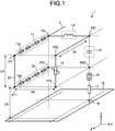
- FIG. 1 is a schematic diagram illustrating a configuration of a direct-current circuit breaker 1 according to a first embodiment of the present invention.
- FIG. 2 is a circuit diagram of the direct-current circuit breaker 1 according to the first embodiment.
- the direct-current circuit breaker 1 is a mechanical circuit breaker of a forced-extinction type.
- the direct-current circuit breaker 1 is provided on a direct-current line 2 of a power system.
- the direct-current circuit breaker 1 interrupts a direct current at a current zero point formed by superimposing an oscillating current on the direct current flowing through the direct-current line 2.
- the direct-current circuit breaker 1 interrupts a short-circuit current or an earth fault current upon occurrence of an accident, thereby protecting a load facility.
- Components of the direct-current circuit breaker 1 are three-dimensionally arranged in a three-dimensional space.
- FIG. 1 the three-dimensional arrangement of the components and the connection between the components are schematically illustrated.
- the direct-current circuit breaker 1 includes a circuit breaker unit 11 inserted in the direct-current line 2, and a circuit unit 10 which is connected in parallel to the circuit breaker unit 11 and generates an oscillating current.
- the circuit unit 10 functions as a resonance circuit.
- When in a steady state i.e., when the power system is in a steady state, the circuit breaker unit 11 is closed and a direct current flows through the direct-current line 2.
- the circuit breaker unit 11 performs an opening operation, and thereby the direct-current circuit breaker 1 interrupts the direct current.
- the opening operation is an operation to an open state from a closed state.
- the circuit unit 10 includes a capacitor 15 and a reactor 14 which are connected in series to each other and generate an oscillating current, and a high-speed closer 12 which is connected in series to the capacitor 15 and performs closing for forming a current zero point.
- the circuit unit 10 further includes a lightning arrester 13 for reducing an overvoltage of the capacitor 15, the lightning arrester 13 being connected in parallel to the capacitor 15 and the high-speed closer 12.
- One end of the high-speed closer 12 is connected to point P1 on an upstream side of the circuit breaker unit 11 in the direct current.
- the other end of the high-speed closer 12 is connected to one electrode of the capacitor 15.
- One end of the reactor 14 is connected to point P4 on a downstream side of the circuit breaker unit 11 in the direct current.
- the other end of the reactor 14 is connected to the other electrode of the capacitor 15.
- One end of the lightning arrester 13 is connected to point P1' between point P1 and the high-speed closer 12.
- the other end of the lightning arrester 13 is connected to point P2 between the capacitor 15 and the reactor 14.
- the circuit unit 10 further includes a charging resistor 17 for charging the capacitor 15 by a direct-current voltage of the direct-current line 2 when in the steady state, and a disconnector 16 provided between the capacitor 15 and the charging resistor 17.
- One end of the disconnector 16 is connected to point P3 between the high-speed closer 12 and the capacitor 15.
- the charging resistor 17 is connected between the other end of the disconnector 16 and a ground electrode 19.
- the circuit breaker unit 11 When in the steady state, the circuit breaker unit 11 is closed and the high-speed closer 12 is open. The capacitor 15 is charged by the direct-current voltage when in the steady state. When an accident occurs, the circuit breaker unit 11 performs the opening operation and the high-speed closer 12 performs a closing operation. The closing operation is an operation to the closed state from the open state.
- the high-speed closer 12 When the high-speed closer 12 is closed, electric charges from a capacitor 5 are discharged to a loop including the high-speed closer 12, the capacitor 15, the reactor 14, and the circuit breaker unit 11. When the electric charges are discharged from the capacitor 5, an oscillating current which passes through the reactor 14, the circuit breaker unit 11, and the high-speed closer 12 flows from the capacitor 15.
- the direct-current circuit breaker 1 superimposes, on an accident current at the circuit breaker unit 11, the oscillating current in a direction opposite to the direction of the direct current, which is the accident current.
- the current zero point is formed by superimposing the oscillating current on the accident current, the extinction of arc is completed in the circuit breaker unit 11 during the opening operation.
- the lightning arrester 13 reduces an overvoltage generated during the opening operation by the circuit breaker unit 11.
- the disconnector 16 When the power system returns to the steady state, the disconnector 16 performs the closing operation. By the disconnector 16 in a closed state, a current flows from the direct-current line 2 to the capacitor 15, and the capacitor 15 is charged. When the charging of the capacitor 15 is completed, the disconnector 16 performs the opening operation. In order to compensate for a decrease in electric charges due to a leakage current from the capacitor 15, the capacitor 15 is charged at any time when in the steady state.
- Point P1, point P2, point P3, and point P4 are points having potentials different from one another in a circuit including the circuit breaker unit 11 and the circuit unit 10.
- Point P1 and point P1' are points having the same potential.
- each of points P1, P1', P2, P3, and P4 is a point where ground insulation is required.
- X, Y, and Z directions are directions perpendicular to one another.
- the components are three-dimensionally arranged in the X, Y, and Z directions.
- the Z direction is a vertical direction.
- the X and Y directions are directions parallel to a horizontal direction.
- An installation surface 18 is a horizontal ground surface on which the direct-current circuit breaker 1 is installed.
- the ground electrode 19 is embedded below the installation surface 18.
- Point P1 in FIG. 1 corresponds to point P1 in a circuit illustrated in FIG. 2 .
- Point P1' illustrated in FIG. 2 is divided into two points P11 and P12 arranged at an interval in the Y direction in FIG. 1 .
- Point P11 of the two points P11 and P12 is on a side of the high-speed closer 12.
- Point P12 is on a side of the lightning arrester 13.
- Point P2 illustrated in FIG. 2 is divided into two points P21 and P22 arranged at an interval in the X direction in FIG. 1 .
- Point P21 of points P21 and P22 is on a side of the capacitor 15.
- Point P22 is on a side of the lightning arrester 13.
- Point P3 illustrated in FIG. 2 is divided into two points P31 and P32 arranged at an interval in the Y direction in FIG. 1 .
- Point P31 of points P31 and P32 is on a side of the high-speed closer 12.
- Point P32 is on a side of the capacitor 15.
- Point P4 in FIG. 1 corresponds to point P4 in the circuit illustrated in FIG. 2 .
- a wiring line 20 connects respective points on the basis of the circuit illustrated in FIG. 2 .
- Points P11 and P12 are connected by the wiring line 20.
- points P1, P11, and P12 are points having the same potential.
- Points P21 and P22 are connected by the wiring line 20.
- Points P21 and P22 are points having the same potential.
- Points P31 and P32 are connected by the wiring line 20. Points P31 and P32 are points having the same potential.
- the circuit breaker unit 11 includes a plurality of circuit breakers 11a connected in series.
- the circuit breakers 11a are aligned in the X direction.
- the high-speed closer 12 includes a plurality of switches 12a connected in series. The switches 12a are aligned in the X direction.
- a maximum value of a voltage applicable to respective points having potentials different from each other is defined as 1.0 PU, and a certain spatial distance required for insulation between sites to which a voltage of 1.0 PU is applied is defined as an insulation distance.
- the circuit breaker unit 11 and the high-speed closer 12 are aligned in a first direction with distance D1 provided therebetween, distance D1 being equal to or longer than the insulation distance.
- the first direction is the Z direction.
- the circuit breaker unit 11 is arranged above the high-speed closer 12.
- the capacitor 15 is divided into a plurality of capacitors stacked in the Z direction.
- the lightning arrester 13 is divided into a plurality of lightning arresters stacked in the Z direction.
- FIG. 1 the illustration of the capacitors constituting the capacitor 15 and the lightning arresters constituting the lightning arrester 13 is omitted.
- the lightning arrester 13 and the capacitor 15 are aligned in a second direction with distance D2 provided therebetween, distance D2 being equal to or longer than the insulation distance.
- the second direction is a direction which intersects the first direction. In the first embodiment, the second direction is the Y direction.
- a combination of the circuit breaker unit 11 with the high-speed closer 12 and a combination of the lightning arrester 13 with the capacitor 15 are aligned in a third direction with distance D3 provided therebetween, distance D3 being equal to or longer than the insulation distance.
- the third direction is a direction which intersects the first direction and the second direction. In the first embodiment, the third direction is the Y direction. D1, distance D2, and distance D3 are any distances equal to or longer than the insulation distance.
- Each of the circuit breaker unit 11, the high-speed closer 12, the lightning arrester 13, the reactor 14, and the capacitor 15 is arranged at a position away from the installation surface 18 so as to be insulated from the installation surface 18.
- Each of the circuit breaker unit 11, the high-speed closer 12, the lightning arrester 13, the reactor 14, and the capacitor 15 is arranged at a position away from the installation surface 18 in the Z direction by a distance equal to or longer than distance D4.
- Distance D4 is a spatial distance required for ground insulation with respect to the installation surface 18.
- each of eight points P1, P4, P11, P12, P21, P22, P31, and P32 is arranged so as to correspond to one of eight corners of one rectangular parallelepiped.
- the length of each side of the rectangular parallelepiped is equal to or longer than the insulation distance.
- Each of the circuit breaker unit 11, the high-speed closer 12, the lightning arrester 13, the reactor 14, and the capacitor 15 is arranged so as to correspond to one of the sides constituting the rectangular parallelepiped.
- the respective components of the circuit breaker unit 11, the high-speed closer 12, the lightning arrester 13, the reactor 14, and the capacitor 15 are arranged to be three-dimensionally aligned in the three-dimensional space.
- points having potentials different from each other out of points P1, P4, P11, P12, P21, P22, P31, and P32 are arranged at a distance equal to or longer than the insulation distance.
- the circuit breaker unit 11, the high-speed closer 12, the lightning arrester 13, the reactor 14, and the capacitor 15 are all arranged at a distance equal to or longer than the insulation distance.
- the respective components can be connected so that none of the wiring lines 20 drawn between the respective components intersect each other by the three-dimensional arrangement of the respective components.
- the respective components can be connected to by the wiring line 20 with simple routing.
- the direct-current circuit breaker 1 can reduce the area of an XY plane, which is an area required for the installation of the respective components, as compared with a case of a planar arrangement in which the respective components are aligned on a plane.
- the direct-current circuit breaker 1 ensures insulation of each site with the use of the spatial distances in the three directions of the X direction, the Y direction, and the Z direction.
- the direct-current circuit breaker 1 in each of the three directions does not need to significantly expand beyond a dimension corresponding to the insulation distance, it is possible to prevent the direct-current circuit breaker 1 from increasing in size in such a way that the dimension of the direct-current circuit breaker 1 in each of the three directions is significantly expanded beyond the dimension corresponding to the insulation distance. As a result, the direct-current circuit breaker 1 can prevent the configuration thereof from increasing in size while providing the insulation distance between the components.
- the circuit breaker unit 11, the high-speed closer 12, the lightning arrester 13, the reactor 14, and the capacitor 15 do not have to be arranged along the sides of the rectangular parallelepiped.
- the arrangement of each of the circuit breaker unit 11, the high-speed closer 12, the lightning arrester 13, the reactor 14, and the capacitor 15 may be appropriately changed on the basis of a positional relationship corresponding to the rectangular parallelepiped.
- the first direction, the second direction, and the third direction are not limited to directions perpendicular to one another, and are only required to be directions which intersect one another.
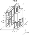
- FIG. 3 is a diagram illustrating an example installation of the direct-current circuit breaker 1 according to the first embodiment.
- the illustration of the circuit breakers 11a and the switches 12a is omitted.
- a plurality of support bases 22 is set up on the installation surface 18.
- Each support base 22 includes a combination of a support post 22a set up in the vertical direction with a flat plate 22b horizontally supported by the support post 22a.
- An insulating material is used as a material for the support post 22a and the flat plate 22b.
- the circuit breaker unit 11 and the high-speed closer 12 are arranged on the support base 22 shared thereby.
- the circuit breaker unit 11 is arranged on the flat plate 22b located at a position higher than the flat plate 22b on which the high-speed closer 12 is arranged.
- the circuit breaker unit 11 and the high-speed closer 12 are aligned in the Z direction with distance D1 provided therebetween.
- distance D1 provided therebetween is that a distance between an end of the circuit breaker unit 11 on a side of the high-speed closer 12 and an end of the high-speed closer 12 on a side of the circuit breaker unit 11 is distance D1.
- the support base 22 on which the lightning arrester 13 is arranged and the support base 22 on which the capacitor 15 is arranged are aligned in the X direction.
- the lightning arrester 13 and the capacitor 15 are aligned in the X direction with distance D2 provided therebetween.
- distance D2 provided therebetween is that a distance between an end of the lightning arrester 13 on a side of the capacitor 15 and an end of the capacitor 15 on a side of the lightning arrester 13 is distance D2.
- the support base 22 on which the lightning arrester 13 is arranged is aligned in the Y direction with the support base 22 on which the circuit breaker unit 11 and the high-speed closer 12 are arranged.
- the support base 22 on which the capacitor 15 is arranged is aligned in the Y direction with the support base 22 on which the circuit breaker unit 11 and the high-speed closer 12 are arranged.
- distance D3 a distance between an end of each of the circuit breaker unit 11 and the high-speed closer 12 on a side of the lightning arrester 13 and the capacitor 15, and an end of each of the lightning arrester 13 and the capacitor 15 on a side of the circuit breaker unit 11 and the high-speed closer 12 is distance D3.
- the circuit breaker unit 11, the high-speed closer 12, the lightning arrester 13, the reactor 14, and the capacitor 15 are each arranged on the flat plate 22b located at a position higher than the installation surface 18.
- the circuit breaker unit 11, the high-speed closer 12, the lightning arrester 13, the reactor 14, and the capacitor 15 are each arranged at a position away from the installation surface 18 in the Z direction by a distance equal to or longer than distance D4.
- the disconnector 16 and the charging resistor 17 are arranged on the flat plate 22b of the support base 22 on which the capacitor 15 is arranged, the flat plate 22b being present on the installation surface 18.
- the arrangement of the support base 22 is not limited to that illustrated in FIG. 3 . Any arrangement may be employed as the arrangement of the support base 22 as long as the three-dimensional arrangement illustrated in FIG. 1 can be realized.
- the arrangement of the respective components of the direct-current circuit breaker 1 may be that obtained by vertically reversing the arrangement in the case illustrated in FIG. 1 .
- the arrangement of the respective components of the direct-current circuit breaker 1 may be that obtained by rotating the arrangement in the case illustrated in FIG. 1 by 90 degrees around an X axis or a Y axis.
- the arrangement of the respective components of the direct-current circuit breaker 1 may be that obtained by laterally reversing the arrangement in the case illustrated in FIG. 1 .
- any orientation of the arrangement thereof may be employed as long as a relative positional relationship between the components satisfies the positional relationship illustrated in FIG. 1 .
- the installation surface 18 may be a roof of a building other than the ground surface.
- the respective components of the direct-current circuit breaker 1 may be installed in a structure suspended from a roof inside a building.
- the circuit breaker unit 11 and the high-speed closer 12 are aligned in the first direction with a distance provided therebetween, the distance being equal to or longer than the insulation distance.
- the capacitor 15 and the lightning arrester 13 are aligned in the second direction with a distance provided therebetween, the distance being equal to or longer than the insulation distance.
- the combination of the circuit breaker unit 11 with the high-speed closer 12 and the combination of the capacitor 15 with the lightning arrester 13 are aligned in the third direction with a distance provided therebetween, the distance being equal to or longer than the insulation distance.
- the direct-current circuit breaker 1 can ensure insulation between sites having different potentials by the three-dimensional arrangement of the respective components of the circuit breaker unit 11, the high-speed closer 12, the lightning arrester 13, the reactor 14, and the capacitor 15. In addition, the direct-current circuit breaker 1 can prevent the configuration thereof from increasing in size by the three-dimensional arrangement of the respective components. As a result of the above, the direct-current circuit breaker 1 achieves an effect that it is possible to ensure insulation between sites having different potentials and to prevent the configuration thereof from increasing in size.
Landscapes
- Engineering & Computer Science (AREA)
- Power Engineering (AREA)
- Gas-Insulated Switchgears (AREA)
- Driving Mechanisms And Operating Circuits Of Arc-Extinguishing High-Tension Switches (AREA)
- Emergency Protection Circuit Devices (AREA)
Abstract
Description
- The present invention relates to a direct-current circuit breaker which interrupts a direct current.
- As one of methods of interruption using a direct-current circuit breaker, a method is known in which a current zero point is formed by superimposing an oscillating current on a direct current to interrupt the direct current at the current zero point.
- Patent Literature 1 discloses a direct-current circuit breaker including a circuit breaker unit inserted in a direct-current line and a resonance circuit which generates an oscillating current. In the direct-current circuit breaker of Patent Literature 1, the circuit breaker unit and components of the resonance circuit are installed on a shared frame, and thereby the circuit breaker unit and the resonance circuit are integrated and located in a switchboard.
- Patent Literature 1:
Japanese Patent Application Laid-open No. 2010-192305 - In direct-current circuit breakers, it is necessary to provide a spatial distance for insulation between sites having different potentials. The higher the rated voltage of such a direct-current circuit breaker, the longer the spatial distance required for insulation in the direct-current circuit breaker, and therefore the more restriction on a physical configuration thereof. In the conventional technique disclosed in Patent Literature 1 described above, it is difficult to provide a spatial distance for insulation between respective components when the rated voltage of the direct-current circuit breaker is higher than that when the direct-current circuit breaker is located in a switchboard, for example, when the rated voltage is 70 kV or higher. In addition, according to the conventional technique disclosed in Patent Literature 1 described above, as the spatial distance between the components increases, the configuration of the direct-current circuit breaker increases in size, which may result in difficulty in installation of the direct-current circuit breaker. The direct-current circuit breakers are required to be able to ensure insulation between sites having different potentials and to prevent the configuration thereof from increasing in size.
- The present invention has been made in view of the above, and an object thereof is to obtain a direct-current circuit breaker capable of ensuring insulation between sites having different potentials and preventing the configuration thereof from increasing in size.
- In order to solve the above-described problems and achieve the object, a direct-current circuit breaker according to the present invention interrupts a direct current at a current zero point formed by superimposing an oscillating current on the direct current flowing through a direct-current line. The direct-current circuit breaker according to the present invention includes a circuit breaker unit inserted in the direct-current line, and a circuit unit that is connected in parallel to the circuit breaker unit and generates the oscillating current. The circuit unit includes a capacitor and a reactor that are connected in series to each other and generate the oscillating current, a high-speed closer that is connected in series to the capacitor and performs closing for forming the current zero point, and a lightning arrester that reduces an overvoltage of the capacitor, the lightning arrester being connected in parallel to the capacitor and the high-speed closer. The circuit breaker unit and the high-speed closer are aligned in a first direction with a distance provided therebetween, the distance being equal to or longer than a certain spatial distance. The capacitor and the lightning arrester are aligned in a second direction that is a direction intersecting the first direction with a distance provided therebetween, the distance being equal to or longer than the spatial distance. A combination of the circuit breaker unit with the high-speed closer and a combination of the capacitor with the lightning arrester are aligned in a third direction that is a direction intersecting the first direction and the second direction with a distance provided therebetween, the distance being equal to or longer than the spatial distance.
- The present invention achieves an effect that it is possible to ensure insulation between sites having different potentials and to prevent the configuration from increasing in size.
-
-
FIG. 1 is a schematic diagram illustrating a configuration of a direct-current circuit breaker according to a first embodiment of the present invention. -
FIG. 2 is a circuit diagram of the direct-current circuit breaker according to the first embodiment. -
FIG. 3 is a diagram illustrating an example installation of the direct-current circuit breaker according to the first embodiment. - Hereinafter, a direct-current circuit breaker according to each embodiment of the present invention will be described in detail with reference to the drawings. The present invention is not limited to the embodiments.
-
FIG. 1 is a schematic diagram illustrating a configuration of a direct-current circuit breaker 1 according to a first embodiment of the present invention.FIG. 2 is a circuit diagram of the direct-current circuit breaker 1 according to the first embodiment. The direct-current circuit breaker 1 is a mechanical circuit breaker of a forced-extinction type. The direct-current circuit breaker 1 is provided on a direct-current line 2 of a power system. The direct-current circuit breaker 1 interrupts a direct current at a current zero point formed by superimposing an oscillating current on the direct current flowing through the direct-current line 2. The direct-current circuit breaker 1 interrupts a short-circuit current or an earth fault current upon occurrence of an accident, thereby protecting a load facility. - Components of the direct-current circuit breaker 1 are three-dimensionally arranged in a three-dimensional space. In
FIG. 1 , the three-dimensional arrangement of the components and the connection between the components are schematically illustrated. - Here, the components of the direct-current circuit breaker 1 will be described with reference to
FIG. 2 . The direct-current circuit breaker 1 includes acircuit breaker unit 11 inserted in the direct-current line 2, and acircuit unit 10 which is connected in parallel to thecircuit breaker unit 11 and generates an oscillating current. The circuit unit 10 functions as a resonance circuit. When in a steady state, i.e., when the power system is in a steady state, thecircuit breaker unit 11 is closed and a direct current flows through the direct-current line 2. When an accident occurs in the power system, thecircuit breaker unit 11 performs an opening operation, and thereby the direct-current circuit breaker 1 interrupts the direct current. The opening operation is an operation to an open state from a closed state. - The
circuit unit 10 includes acapacitor 15 and areactor 14 which are connected in series to each other and generate an oscillating current, and a high-speed closer 12 which is connected in series to thecapacitor 15 and performs closing for forming a current zero point. Thecircuit unit 10 further includes alightning arrester 13 for reducing an overvoltage of thecapacitor 15, thelightning arrester 13 being connected in parallel to thecapacitor 15 and the high-speed closer 12. - One end of the high-speed closer 12 is connected to point P1 on an upstream side of the
circuit breaker unit 11 in the direct current. The other end of the high-speed closer 12 is connected to one electrode of thecapacitor 15. One end of thereactor 14 is connected to point P4 on a downstream side of thecircuit breaker unit 11 in the direct current. The other end of thereactor 14 is connected to the other electrode of thecapacitor 15. One end of thelightning arrester 13 is connected to point P1' between point P1 and the high-speed closer 12. The other end of thelightning arrester 13 is connected to point P2 between thecapacitor 15 and thereactor 14. - The
circuit unit 10 further includes acharging resistor 17 for charging thecapacitor 15 by a direct-current voltage of the direct-current line 2 when in the steady state, and adisconnector 16 provided between thecapacitor 15 and thecharging resistor 17. One end of thedisconnector 16 is connected to point P3 between the high-speed closer 12 and thecapacitor 15. Thecharging resistor 17 is connected between the other end of thedisconnector 16 and aground electrode 19. - When in the steady state, the
circuit breaker unit 11 is closed and the high-speed closer 12 is open. Thecapacitor 15 is charged by the direct-current voltage when in the steady state. When an accident occurs, thecircuit breaker unit 11 performs the opening operation and the high-speed closer 12 performs a closing operation. The closing operation is an operation to the closed state from the open state. When the high-speed closer 12 is closed, electric charges from a capacitor 5 are discharged to a loop including the high-speed closer 12, thecapacitor 15, thereactor 14, and thecircuit breaker unit 11. When the electric charges are discharged from the capacitor 5, an oscillating current which passes through thereactor 14, thecircuit breaker unit 11, and the high-speed closer 12 flows from thecapacitor 15. As a result, the direct-current circuit breaker 1 superimposes, on an accident current at thecircuit breaker unit 11, the oscillating current in a direction opposite to the direction of the direct current, which is the accident current. When the current zero point is formed by superimposing the oscillating current on the accident current, the extinction of arc is completed in thecircuit breaker unit 11 during the opening operation. Thelightning arrester 13 reduces an overvoltage generated during the opening operation by thecircuit breaker unit 11. - When the power system returns to the steady state, the
disconnector 16 performs the closing operation. By thedisconnector 16 in a closed state, a current flows from the direct-current line 2 to thecapacitor 15, and thecapacitor 15 is charged. When the charging of thecapacitor 15 is completed, thedisconnector 16 performs the opening operation. In order to compensate for a decrease in electric charges due to a leakage current from thecapacitor 15, thecapacitor 15 is charged at any time when in the steady state. - Point P1, point P2, point P3, and point P4 are points having potentials different from one another in a circuit including the
circuit breaker unit 11 and thecircuit unit 10. Point P1 and point P1' are points having the same potential. In addition, each of points P1, P1', P2, P3, and P4 is a point where ground insulation is required. - Next, with reference to
FIG. 1 , the three-dimensional arrangement of the components of the direct-current circuit breaker 1 and the connection between the components will be described. InFIG. 1 , X, Y, and Z directions are directions perpendicular to one another. The components are three-dimensionally arranged in the X, Y, and Z directions. The Z direction is a vertical direction. The X and Y directions are directions parallel to a horizontal direction. Aninstallation surface 18 is a horizontal ground surface on which the direct-current circuit breaker 1 is installed. Theground electrode 19 is embedded below theinstallation surface 18. - Point P1 in
FIG. 1 corresponds to point P1 in a circuit illustrated inFIG. 2 . Point P1' illustrated inFIG. 2 is divided into two points P11 and P12 arranged at an interval in the Y direction inFIG. 1 . Point P11 of the two points P11 and P12 is on a side of the high-speed closer 12. Point P12 is on a side of thelightning arrester 13. - Point P2 illustrated in
FIG. 2 is divided into two points P21 and P22 arranged at an interval in the X direction inFIG. 1 . Point P21 of points P21 and P22 is on a side of thecapacitor 15. Point P22 is on a side of thelightning arrester 13. Point P3 illustrated inFIG. 2 is divided into two points P31 and P32 arranged at an interval in the Y direction inFIG. 1 . Point P31 of points P31 and P32 is on a side of the high-speed closer 12. Point P32 is on a side of thecapacitor 15. Point P4 inFIG. 1 corresponds to point P4 in the circuit illustrated inFIG. 2 . - A
wiring line 20 connects respective points on the basis of the circuit illustrated inFIG. 2 . Points P11 and P12 are connected by thewiring line 20. InFIG. 2 , points P1, P11, and P12 are points having the same potential. Points P21 and P22 are connected by thewiring line 20. Points P21 and P22 are points having the same potential. Points P31 and P32 are connected by thewiring line 20. Points P31 and P32 are points having the same potential. - The
circuit breaker unit 11 includes a plurality ofcircuit breakers 11a connected in series. Thecircuit breakers 11a are aligned in the X direction. The high-speed closer 12 includes a plurality ofswitches 12a connected in series. Theswitches 12a are aligned in the X direction. - Here, a maximum value of a voltage applicable to respective points having potentials different from each other is defined as 1.0 PU, and a certain spatial distance required for insulation between sites to which a voltage of 1.0 PU is applied is defined as an insulation distance.
Thecircuit breaker unit 11 and the high-speed closer 12 are aligned in a first direction with distance D1 provided therebetween, distance D1 being equal to or longer than the insulation distance. In the first embodiment, the first direction is the Z direction. Thecircuit breaker unit 11 is arranged above the high-speed closer 12. - The
capacitor 15 is divided into a plurality of capacitors stacked in the Z direction. Thelightning arrester 13 is divided into a plurality of lightning arresters stacked in the Z direction. InFIG. 1 , the illustration of the capacitors constituting thecapacitor 15 and the lightning arresters constituting thelightning arrester 13 is omitted. Thelightning arrester 13 and thecapacitor 15 are aligned in a second direction with distance D2 provided therebetween, distance D2 being equal to or longer than the insulation distance. The second direction is a direction which intersects the first direction. In the first embodiment, the second direction is the Y direction. - A combination of the
circuit breaker unit 11 with the high-speed closer 12 and a combination of thelightning arrester 13 with thecapacitor 15 are aligned in a third direction with distance D3 provided therebetween, distance D3 being equal to or longer than the insulation distance. The third direction is a direction which intersects the first direction and the second direction. In the first embodiment, the third direction is the Y direction. D1, distance D2, and distance D3 are any distances equal to or longer than the insulation distance. - Each of the
circuit breaker unit 11, the high-speed closer 12, thelightning arrester 13, thereactor 14, and thecapacitor 15 is arranged at a position away from theinstallation surface 18 so as to be insulated from theinstallation surface 18. Each of thecircuit breaker unit 11, the high-speed closer 12, thelightning arrester 13, thereactor 14, and thecapacitor 15 is arranged at a position away from theinstallation surface 18 in the Z direction by a distance equal to or longer than distance D4. Distance D4 is a spatial distance required for ground insulation with respect to theinstallation surface 18. As a result, insulation of thecircuit breaker unit 11, the high-speed closer 12, thelightning arrester 13, thereactor 14, and thecapacitor 15 from theinstallation surface 18 is ensured. - In the example illustrated in
FIG. 1 , each of eight points P1, P4, P11, P12, P21, P22, P31, and P32 is arranged so as to correspond to one of eight corners of one rectangular parallelepiped. The length of each side of the rectangular parallelepiped is equal to or longer than the insulation distance. Each of thecircuit breaker unit 11, the high-speed closer 12, thelightning arrester 13, thereactor 14, and thecapacitor 15 is arranged so as to correspond to one of the sides constituting the rectangular parallelepiped. As described above, the respective components of thecircuit breaker unit 11, the high-speed closer 12, thelightning arrester 13, thereactor 14, and thecapacitor 15 are arranged to be three-dimensionally aligned in the three-dimensional space. - By such a positional relationship among the respective components, points having potentials different from each other out of points P1, P4, P11, P12, P21, P22, P31, and P32 are arranged at a distance equal to or longer than the insulation distance. The
circuit breaker unit 11, the high-speed closer 12, thelightning arrester 13, thereactor 14, and thecapacitor 15 are all arranged at a distance equal to or longer than the insulation distance. As a result, the direct-current circuit breaker 1 can ensure insulation between sites having different potentials. - In addition, the respective components can be connected so that none of the
wiring lines 20 drawn between the respective components intersect each other by the three-dimensional arrangement of the respective components. In the direct-current circuit breaker 1, the respective components can be connected to by thewiring line 20 with simple routing. - The direct-current circuit breaker 1 can reduce the area of an XY plane, which is an area required for the installation of the respective components, as compared with a case of a planar arrangement in which the respective components are aligned on a plane. In addition, by employing, as arrangement of the respective components, a three-dimensional arrangement corresponding to the above-described rectangular parallelepiped, the direct-current circuit breaker 1 ensures insulation of each site with the use of the spatial distances in the three directions of the X direction, the Y direction, and the Z direction. Since the dimension of the direct-current circuit breaker 1 in each of the three directions does not need to significantly expand beyond a dimension corresponding to the insulation distance, it is possible to prevent the direct-current circuit breaker 1 from increasing in size in such a way that the dimension of the direct-current circuit breaker 1 in each of the three directions is significantly expanded beyond the dimension corresponding to the insulation distance. As a result, the direct-current circuit breaker 1 can prevent the configuration thereof from increasing in size while providing the insulation distance between the components.
- The
circuit breaker unit 11, the high-speed closer 12, thelightning arrester 13, thereactor 14, and thecapacitor 15 do not have to be arranged along the sides of the rectangular parallelepiped. The arrangement of each of thecircuit breaker unit 11, the high-speed closer 12, thelightning arrester 13, thereactor 14, and thecapacitor 15 may be appropriately changed on the basis of a positional relationship corresponding to the rectangular parallelepiped. The first direction, the second direction, and the third direction are not limited to directions perpendicular to one another, and are only required to be directions which intersect one another. -
FIG. 3 is a diagram illustrating an example installation of the direct-current circuit breaker 1 according to the first embodiment. InFIG. 3 , the illustration of thecircuit breakers 11a and theswitches 12a is omitted. A plurality of support bases 22 is set up on theinstallation surface 18. Eachsupport base 22 includes a combination of asupport post 22a set up in the vertical direction with aflat plate 22b horizontally supported by thesupport post 22a. An insulating material is used as a material for thesupport post 22a and theflat plate 22b. - The
circuit breaker unit 11 and the high-speed closer 12 are arranged on thesupport base 22 shared thereby. Thecircuit breaker unit 11 is arranged on theflat plate 22b located at a position higher than theflat plate 22b on which the high-speed closer 12 is arranged.
As a result, thecircuit breaker unit 11 and the high-speed closer 12 are aligned in the Z direction with distance D1 provided therebetween. What is meant by "with distance D1 provided therebetween" is that a distance between an end of thecircuit breaker unit 11 on a side of the high-speed closer 12 and an end of the high-speed closer 12 on a side of thecircuit breaker unit 11 is distance D1. - The
support base 22 on which thelightning arrester 13 is arranged and thesupport base 22 on which thecapacitor 15 is arranged are aligned in the X direction. As a result, thelightning arrester 13 and thecapacitor 15 are aligned in the X direction with distance D2 provided therebetween. What is meant by "with distance D2 provided therebetween" is that a distance between an end of thelightning arrester 13 on a side of thecapacitor 15 and an end of thecapacitor 15 on a side of thelightning arrester 13 is distance D2. - The
support base 22 on which thelightning arrester 13 is arranged is aligned in the Y direction with thesupport base 22 on which thecircuit breaker unit 11 and the high-speed closer 12 are arranged. Thesupport base 22 on which thecapacitor 15 is arranged is aligned in the Y direction with thesupport base 22 on which thecircuit breaker unit 11 and the high-speed closer 12 are arranged. As a result, the combination of thecircuit breaker unit 11 with the high-speed closer 12 and the combination of thelightning arrester 13 with thecapacitor 15 are aligned in the Y direction with distance D3 provided therebetween. What is meant by "with distance D3 provided therebetween" is that a distance between an end of each of thecircuit breaker unit 11 and the high-speed closer 12 on a side of thelightning arrester 13 and thecapacitor 15, and an end of each of thelightning arrester 13 and thecapacitor 15 on a side of thecircuit breaker unit 11 and the high-speed closer 12 is distance D3. - The
circuit breaker unit 11, the high-speed closer 12, thelightning arrester 13, thereactor 14, and thecapacitor 15 are each arranged on theflat plate 22b located at a position higher than theinstallation surface 18. As a result, thecircuit breaker unit 11, the high-speed closer 12, thelightning arrester 13, thereactor 14, and thecapacitor 15 are each arranged at a position away from theinstallation surface 18 in the Z direction by a distance equal to or longer than distance D4. Thedisconnector 16 and the chargingresistor 17 are arranged on theflat plate 22b of thesupport base 22 on which thecapacitor 15 is arranged, theflat plate 22b being present on theinstallation surface 18. - The arrangement of the
support base 22 is not limited to that illustrated inFIG. 3 . Any arrangement may be employed as the arrangement of thesupport base 22 as long as the three-dimensional arrangement illustrated inFIG. 1 can be realized. In addition, the arrangement of the respective components of the direct-current circuit breaker 1 may be that obtained by vertically reversing the arrangement in the case illustrated inFIG. 1 . The arrangement of the respective components of the direct-current circuit breaker 1 may be that obtained by rotating the arrangement in the case illustrated inFIG. 1 by 90 degrees around an X axis or a Y axis. The arrangement of the respective components of the direct-current circuit breaker 1 may be that obtained by laterally reversing the arrangement in the case illustrated inFIG. 1 . Regarding the respective components, any orientation of the arrangement thereof may be employed as long as a relative positional relationship between the components satisfies the positional relationship illustrated inFIG. 1 . Theinstallation surface 18 may be a roof of a building other than the ground surface. The respective components of the direct-current circuit breaker 1 may be installed in a structure suspended from a roof inside a building. - According to the first embodiment, the
circuit breaker unit 11 and the high-speed closer 12 are aligned in the first direction with a distance provided therebetween, the distance being equal to or longer than the insulation distance. Thecapacitor 15 and thelightning arrester 13 are aligned in the second direction with a distance provided therebetween, the distance being equal to or longer than the insulation distance. The combination of thecircuit breaker unit 11 with the high-speed closer 12 and the combination of thecapacitor 15 with thelightning arrester 13 are aligned in the third direction with a distance provided therebetween, the distance being equal to or longer than the insulation distance. The direct-current circuit breaker 1 can ensure insulation between sites having different potentials by the three-dimensional arrangement of the respective components of thecircuit breaker unit 11, the high-speed closer 12, thelightning arrester 13, thereactor 14, and thecapacitor 15. In addition, the direct-current circuit breaker 1 can prevent the configuration thereof from increasing in size by the three-dimensional arrangement of the respective components. As a result of the above, the direct-current circuit breaker 1 achieves an effect that it is possible to ensure insulation between sites having different potentials and to prevent the configuration thereof from increasing in size. - The configurations described in the embodiments above are merely examples of the content of the present invention and can be combined with other known technology and part thereof can be omitted or modified without departing from the gist of the present invention.
- 1 direct-current circuit breaker; 2 direct-current line; 10 circuit unit; 11 circuit breaker unit; 11a circuit breaker; 12 high-speed closer; 12a switch; 13 lightning arrester; 14 reactor; 15 capacitor; 16 disconnector; 17 charging resistor; 18 installation surface; 19 ground electrode; 20 wiring line; 22 support base; 22a support post; 22b flat plate.
Claims (4)
- A direct-current circuit breaker that interrupts a direct current at a current zero point formed by superimposing an oscillating current on the direct current flowing through a direct-current line, the direct-current circuit breaker comprising:a circuit breaker unit inserted in the direct-current line; anda circuit unit connected in parallel to the circuit breaker unit to generate the oscillating current, whereinthe circuit unit includes:a capacitor and a reactor connected in series to each other to generate the oscillating current;a high-speed closer connected in series to the capacitor to perform closing for forming the current zero point; anda lightning arrester to reduce an overvoltage of the capacitor, the lightning arrester being connected in parallel to the capacitor and the high-speed closer,the circuit breaker unit and the high-speed closer are aligned in a first direction with a distance provided therebetween, the distance being equal to or longer than a certain spatial distance,the capacitor and the lightning arrester are aligned in a second direction that is a direction intersecting the first direction with a distance provided therebetween, the distance being equal to or longer than the spatial distance, anda combination of the circuit breaker unit with the high-speed closer and a combination of the capacitor with the lightning arrester are aligned in a third direction that is a direction intersecting the first direction and the second direction with a distance provided therebetween, the distance being equal to or longer than the spatial distance.
- The direct-current circuit breaker according to claim 1, wherein the first direction, the second direction, and the third direction are perpendicular to one another.
- The direct-current circuit breaker according to claim 1, wherein the spatial distance is a distance capable of insulating between sites to which a voltage with a maximum value is applied, the maximum value being a maximum value of a voltage applicable to respective points having potentials different from each other in a circuit including the circuit breaker unit and the circuit unit.
- The direct-current circuit breaker according to claim 1, wherein each of the circuit breaker unit, the capacitor, the reactor, the high-speed closer, and the lightning arrester is arranged at a position away from an installation surface on which the direct-current circuit breaker is installed so as to be insulated from the installation surface.
Applications Claiming Priority (1)
| Application Number | Priority Date | Filing Date | Title |
|---|---|---|---|
| PCT/JP2018/045273 WO2020121369A1 (en) | 2018-12-10 | 2018-12-10 | Direct-current circuit breaker |
Publications (3)
| Publication Number | Publication Date |
|---|---|
| EP3896714A1 true EP3896714A1 (en) | 2021-10-20 |
| EP3896714A4 EP3896714A4 (en) | 2021-12-29 |
| EP3896714B1 EP3896714B1 (en) | 2024-03-13 |
Family
ID=70000819
Family Applications (1)
| Application Number | Title | Priority Date | Filing Date |
|---|---|---|---|
| EP18943317.0A Active EP3896714B1 (en) | 2018-12-10 | 2018-12-10 | Direct-current circuit breaker |
Country Status (4)
| Country | Link |
|---|---|
| US (1) | US11380500B2 (en) |
| EP (1) | EP3896714B1 (en) |
| JP (1) | JP6671547B1 (en) |
| WO (1) | WO2020121369A1 (en) |
Cited By (1)
| Publication number | Priority date | Publication date | Assignee | Title |
|---|---|---|---|---|
| EP4261865A4 (en) * | 2020-12-09 | 2024-03-06 | Mitsubishi Electric Corporation | DC CIRCUIT BREAKER AND DC CIRCUIT BREAKER SYSTEM |
Families Citing this family (1)
| Publication number | Priority date | Publication date | Assignee | Title |
|---|---|---|---|---|
| JP6704539B1 (en) * | 2019-05-28 | 2020-06-03 | 三菱電機株式会社 | Breaker |
Family Cites Families (9)
| Publication number | Priority date | Publication date | Assignee | Title |
|---|---|---|---|---|
| JPS58197619A (en) * | 1982-05-13 | 1983-11-17 | 株式会社東芝 | Dc breaking device |
| JP2000048686A (en) * | 1998-07-29 | 2000-02-18 | Hitachi Ltd | Commutation type DC circuit breaker |
| JP3965037B2 (en) * | 2001-10-12 | 2007-08-22 | 東芝三菱電機産業システム株式会社 | DC vacuum interrupter |
| JP4923072B2 (en) * | 2009-02-19 | 2012-04-25 | 株式会社日立製作所 | Commutation type DC circuit breaker |
| KR20150078491A (en) * | 2013-12-30 | 2015-07-08 | 주식회사 효성 | High-voltage DC circuit breaker |
| KR101550374B1 (en) * | 2013-12-31 | 2015-09-04 | 주식회사 효성 | High-voltage DC circuit breaker |
| EP3059827A1 (en) * | 2015-02-20 | 2016-08-24 | ABB Technology Ltd | Switching system for breaking a current and method of performing a current breaking operation |
| WO2018229970A1 (en) * | 2017-06-16 | 2018-12-20 | 東芝エネルギーシステムズ株式会社 | Direct-current circuit breaker, mechanical switching device for direct-current circuit breaker and semiconductor switching device for direct current circuit breaker |
| EP4160640B1 (en) * | 2017-07-11 | 2025-10-22 | Mitsubishi Electric Corporation | Direct-current circuit breaker |
-
2018
- 2018-12-10 EP EP18943317.0A patent/EP3896714B1/en active Active
- 2018-12-10 WO PCT/JP2018/045273 patent/WO2020121369A1/en not_active Ceased
- 2018-12-10 US US17/277,523 patent/US11380500B2/en active Active
- 2018-12-10 JP JP2019519789A patent/JP6671547B1/en active Active
Cited By (2)
| Publication number | Priority date | Publication date | Assignee | Title |
|---|---|---|---|---|
| EP4261865A4 (en) * | 2020-12-09 | 2024-03-06 | Mitsubishi Electric Corporation | DC CIRCUIT BREAKER AND DC CIRCUIT BREAKER SYSTEM |
| US12243697B2 (en) | 2020-12-09 | 2025-03-04 | Mitsubishi Electric Corporation | Direct-current circuit breaker and direct-current circuit breaker system |
Also Published As
| Publication number | Publication date |
|---|---|
| WO2020121369A1 (en) | 2020-06-18 |
| US11380500B2 (en) | 2022-07-05 |
| EP3896714B1 (en) | 2024-03-13 |
| EP3896714A4 (en) | 2021-12-29 |
| JPWO2020121369A1 (en) | 2021-02-15 |
| JP6671547B1 (en) | 2020-03-25 |
| US20210358702A1 (en) | 2021-11-18 |
Similar Documents
| Publication | Publication Date | Title |
|---|---|---|
| TW201240253A (en) | Switch gear | |
| US9472926B2 (en) | Gas-insulated switchgear arrangement | |
| CN103368081A (en) | Main electrical connection of double-bus disconnecting link section | |
| EP3640964B1 (en) | Mechanical switching device for direct-current circuit breaker and direct-current circuit breaker comprising the mechanical switching device | |
| TWI505589B (en) | Switchgear and switchgear assembly method | |
| KR101489939B1 (en) | Gas insulated switch-gear | |
| EP3896714B1 (en) | Direct-current circuit breaker | |
| US9081406B2 (en) | Static var compensator including series circuits of three phases that are delta-connected to three-phase AC buses | |
| BRPI1100187A2 (en) | double busbar type switching device | |
| RU2550810C2 (en) | High-voltage switchgear and control gear | |
| CN1674376B (en) | High voltage outdoor substation | |
| US10693289B2 (en) | DC breaker | |
| CN104505758B (en) | Configuration method of 110kV outdoor flexible busbar improved half-high distribution device | |
| Liu et al. | A topology of the multi-port DC circuit breaker for multi-terminal DC system fault protection | |
| KR101338254B1 (en) | Distributing panel for very high voltage | |
| US3117192A (en) | Disconnecting switch with surge protection gaps | |
| CN208922965U (en) | Fusible switch | |
| CN206283311U (en) | A kind of new electrical main connecting wire of transformer station | |
| JP5547694B2 (en) | Gas insulated switchgear | |
| JP3203676U (en) | Gas insulated switchgear | |
| KR101438870B1 (en) | Gas Insulated Switchgear with Shape Memory Alloy | |
| CN207217434U (en) | A circuit breaker box | |
| US9876336B2 (en) | Gas-insulated switching apparatus | |
| KR20190002927U (en) | Connection part between gas insulated switchgear and solid insulated switchgear | |
| JPH07107630A (en) | Gas insulated switchgear |
Legal Events
| Date | Code | Title | Description |
|---|---|---|---|
| STAA | Information on the status of an ep patent application or granted ep patent |
Free format text: STATUS: THE INTERNATIONAL PUBLICATION HAS BEEN MADE |
|
| PUAI | Public reference made under article 153(3) epc to a published international application that has entered the european phase |
Free format text: ORIGINAL CODE: 0009012 |
|
| STAA | Information on the status of an ep patent application or granted ep patent |
Free format text: STATUS: REQUEST FOR EXAMINATION WAS MADE |
|
| 17P | Request for examination filed |
Effective date: 20210521 |
|
| AK | Designated contracting states |
Kind code of ref document: A1 Designated state(s): AL AT BE BG CH CY CZ DE DK EE ES FI FR GB GR HR HU IE IS IT LI LT LU LV MC MK MT NL NO PL PT RO RS SE SI SK SM TR |
|
| A4 | Supplementary search report drawn up and despatched |
Effective date: 20211126 |
|
| RIC1 | Information provided on ipc code assigned before grant |
Ipc: H01H 9/54 20060101ALI20211122BHEP Ipc: H01H 33/59 20060101AFI20211122BHEP |
|
| DAV | Request for validation of the european patent (deleted) | ||
| DAX | Request for extension of the european patent (deleted) | ||
| GRAP | Despatch of communication of intention to grant a patent |
Free format text: ORIGINAL CODE: EPIDOSNIGR1 |
|
| STAA | Information on the status of an ep patent application or granted ep patent |
Free format text: STATUS: GRANT OF PATENT IS INTENDED |
|
| INTG | Intention to grant announced |
Effective date: 20231004 |
|
| P01 | Opt-out of the competence of the unified patent court (upc) registered |
Effective date: 20231128 |
|
| GRAS | Grant fee paid |
Free format text: ORIGINAL CODE: EPIDOSNIGR3 |
|
| GRAA | (expected) grant |
Free format text: ORIGINAL CODE: 0009210 |
|
| STAA | Information on the status of an ep patent application or granted ep patent |
Free format text: STATUS: THE PATENT HAS BEEN GRANTED |
|
| AK | Designated contracting states |
Kind code of ref document: B1 Designated state(s): AL AT BE BG CH CY CZ DE DK EE ES FI FR GB GR HR HU IE IS IT LI LT LU LV MC MK MT NL NO PL PT RO RS SE SI SK SM TR |
|
| REG | Reference to a national code |
Ref country code: GB Ref legal event code: FG4D |
|
| REG | Reference to a national code |
Ref country code: CH Ref legal event code: EP |
|
| REG | Reference to a national code |
Ref country code: DE Ref legal event code: R096 Ref document number: 602018066750 Country of ref document: DE |
|
| REG | Reference to a national code |
Ref country code: SE Ref legal event code: TRGR |
|
| REG | Reference to a national code |
Ref country code: IE Ref legal event code: FG4D |
|
| PG25 | Lapsed in a contracting state [announced via postgrant information from national office to epo] |
Ref country code: LT Free format text: LAPSE BECAUSE OF FAILURE TO SUBMIT A TRANSLATION OF THE DESCRIPTION OR TO PAY THE FEE WITHIN THE PRESCRIBED TIME-LIMIT Effective date: 20240313 |
|
| REG | Reference to a national code |
Ref country code: LT Ref legal event code: MG9D |
|
| PG25 | Lapsed in a contracting state [announced via postgrant information from national office to epo] |
Ref country code: GR Free format text: LAPSE BECAUSE OF FAILURE TO SUBMIT A TRANSLATION OF THE DESCRIPTION OR TO PAY THE FEE WITHIN THE PRESCRIBED TIME-LIMIT Effective date: 20240614 |
|
| REG | Reference to a national code |
Ref country code: NL Ref legal event code: MP Effective date: 20240313 |
|
| PG25 | Lapsed in a contracting state [announced via postgrant information from national office to epo] |
Ref country code: HR Free format text: LAPSE BECAUSE OF FAILURE TO SUBMIT A TRANSLATION OF THE DESCRIPTION OR TO PAY THE FEE WITHIN THE PRESCRIBED TIME-LIMIT Effective date: 20240313 Ref country code: RS Free format text: LAPSE BECAUSE OF FAILURE TO SUBMIT A TRANSLATION OF THE DESCRIPTION OR TO PAY THE FEE WITHIN THE PRESCRIBED TIME-LIMIT Effective date: 20240613 |
|
| PG25 | Lapsed in a contracting state [announced via postgrant information from national office to epo] |
Ref country code: ES Free format text: LAPSE BECAUSE OF FAILURE TO SUBMIT A TRANSLATION OF THE DESCRIPTION OR TO PAY THE FEE WITHIN THE PRESCRIBED TIME-LIMIT Effective date: 20240313 |
|
| PG25 | Lapsed in a contracting state [announced via postgrant information from national office to epo] |
Ref country code: RS Free format text: LAPSE BECAUSE OF FAILURE TO SUBMIT A TRANSLATION OF THE DESCRIPTION OR TO PAY THE FEE WITHIN THE PRESCRIBED TIME-LIMIT Effective date: 20240613 Ref country code: NO Free format text: LAPSE BECAUSE OF FAILURE TO SUBMIT A TRANSLATION OF THE DESCRIPTION OR TO PAY THE FEE WITHIN THE PRESCRIBED TIME-LIMIT Effective date: 20240613 Ref country code: LT Free format text: LAPSE BECAUSE OF FAILURE TO SUBMIT A TRANSLATION OF THE DESCRIPTION OR TO PAY THE FEE WITHIN THE PRESCRIBED TIME-LIMIT Effective date: 20240313 Ref country code: HR Free format text: LAPSE BECAUSE OF FAILURE TO SUBMIT A TRANSLATION OF THE DESCRIPTION OR TO PAY THE FEE WITHIN THE PRESCRIBED TIME-LIMIT Effective date: 20240313 Ref country code: GR Free format text: LAPSE BECAUSE OF FAILURE TO SUBMIT A TRANSLATION OF THE DESCRIPTION OR TO PAY THE FEE WITHIN THE PRESCRIBED TIME-LIMIT Effective date: 20240614 Ref country code: FI Free format text: LAPSE BECAUSE OF FAILURE TO SUBMIT A TRANSLATION OF THE DESCRIPTION OR TO PAY THE FEE WITHIN THE PRESCRIBED TIME-LIMIT Effective date: 20240313 Ref country code: ES Free format text: LAPSE BECAUSE OF FAILURE TO SUBMIT A TRANSLATION OF THE DESCRIPTION OR TO PAY THE FEE WITHIN THE PRESCRIBED TIME-LIMIT Effective date: 20240313 Ref country code: BG Free format text: LAPSE BECAUSE OF FAILURE TO SUBMIT A TRANSLATION OF THE DESCRIPTION OR TO PAY THE FEE WITHIN THE PRESCRIBED TIME-LIMIT Effective date: 20240313 |
|
| REG | Reference to a national code |
Ref country code: AT Ref legal event code: MK05 Ref document number: 1666566 Country of ref document: AT Kind code of ref document: T Effective date: 20240313 |
|
| PG25 | Lapsed in a contracting state [announced via postgrant information from national office to epo] |
Ref country code: LV Free format text: LAPSE BECAUSE OF FAILURE TO SUBMIT A TRANSLATION OF THE DESCRIPTION OR TO PAY THE FEE WITHIN THE PRESCRIBED TIME-LIMIT Effective date: 20240313 |
|
| PG25 | Lapsed in a contracting state [announced via postgrant information from national office to epo] |
Ref country code: NL Free format text: LAPSE BECAUSE OF FAILURE TO SUBMIT A TRANSLATION OF THE DESCRIPTION OR TO PAY THE FEE WITHIN THE PRESCRIBED TIME-LIMIT Effective date: 20240313 |
|
| PG25 | Lapsed in a contracting state [announced via postgrant information from national office to epo] |
Ref country code: NL Free format text: LAPSE BECAUSE OF FAILURE TO SUBMIT A TRANSLATION OF THE DESCRIPTION OR TO PAY THE FEE WITHIN THE PRESCRIBED TIME-LIMIT Effective date: 20240313 |
|
| PG25 | Lapsed in a contracting state [announced via postgrant information from national office to epo] |
Ref country code: IS Free format text: LAPSE BECAUSE OF FAILURE TO SUBMIT A TRANSLATION OF THE DESCRIPTION OR TO PAY THE FEE WITHIN THE PRESCRIBED TIME-LIMIT Effective date: 20240713 |
|
| PG25 | Lapsed in a contracting state [announced via postgrant information from national office to epo] |
Ref country code: PT Free format text: LAPSE BECAUSE OF FAILURE TO SUBMIT A TRANSLATION OF THE DESCRIPTION OR TO PAY THE FEE WITHIN THE PRESCRIBED TIME-LIMIT Effective date: 20240715 Ref country code: SM Free format text: LAPSE BECAUSE OF FAILURE TO SUBMIT A TRANSLATION OF THE DESCRIPTION OR TO PAY THE FEE WITHIN THE PRESCRIBED TIME-LIMIT Effective date: 20240313 |
|
| PG25 | Lapsed in a contracting state [announced via postgrant information from national office to epo] |
Ref country code: EE Free format text: LAPSE BECAUSE OF FAILURE TO SUBMIT A TRANSLATION OF THE DESCRIPTION OR TO PAY THE FEE WITHIN THE PRESCRIBED TIME-LIMIT Effective date: 20240313 Ref country code: CZ Free format text: LAPSE BECAUSE OF FAILURE TO SUBMIT A TRANSLATION OF THE DESCRIPTION OR TO PAY THE FEE WITHIN THE PRESCRIBED TIME-LIMIT Effective date: 20240313 |
|
| PG25 | Lapsed in a contracting state [announced via postgrant information from national office to epo] |
Ref country code: AT Free format text: LAPSE BECAUSE OF FAILURE TO SUBMIT A TRANSLATION OF THE DESCRIPTION OR TO PAY THE FEE WITHIN THE PRESCRIBED TIME-LIMIT Effective date: 20240313 |
|
| PG25 | Lapsed in a contracting state [announced via postgrant information from national office to epo] |
Ref country code: PL Free format text: LAPSE BECAUSE OF FAILURE TO SUBMIT A TRANSLATION OF THE DESCRIPTION OR TO PAY THE FEE WITHIN THE PRESCRIBED TIME-LIMIT Effective date: 20240313 |
|
| PG25 | Lapsed in a contracting state [announced via postgrant information from national office to epo] |
Ref country code: SK Free format text: LAPSE BECAUSE OF FAILURE TO SUBMIT A TRANSLATION OF THE DESCRIPTION OR TO PAY THE FEE WITHIN THE PRESCRIBED TIME-LIMIT Effective date: 20240313 |
|
| PG25 | Lapsed in a contracting state [announced via postgrant information from national office to epo] |
Ref country code: SM Free format text: LAPSE BECAUSE OF FAILURE TO SUBMIT A TRANSLATION OF THE DESCRIPTION OR TO PAY THE FEE WITHIN THE PRESCRIBED TIME-LIMIT Effective date: 20240313 Ref country code: SK Free format text: LAPSE BECAUSE OF FAILURE TO SUBMIT A TRANSLATION OF THE DESCRIPTION OR TO PAY THE FEE WITHIN THE PRESCRIBED TIME-LIMIT Effective date: 20240313 Ref country code: RO Free format text: LAPSE BECAUSE OF FAILURE TO SUBMIT A TRANSLATION OF THE DESCRIPTION OR TO PAY THE FEE WITHIN THE PRESCRIBED TIME-LIMIT Effective date: 20240313 Ref country code: PT Free format text: LAPSE BECAUSE OF FAILURE TO SUBMIT A TRANSLATION OF THE DESCRIPTION OR TO PAY THE FEE WITHIN THE PRESCRIBED TIME-LIMIT Effective date: 20240715 Ref country code: PL Free format text: LAPSE BECAUSE OF FAILURE TO SUBMIT A TRANSLATION OF THE DESCRIPTION OR TO PAY THE FEE WITHIN THE PRESCRIBED TIME-LIMIT Effective date: 20240313 Ref country code: IS Free format text: LAPSE BECAUSE OF FAILURE TO SUBMIT A TRANSLATION OF THE DESCRIPTION OR TO PAY THE FEE WITHIN THE PRESCRIBED TIME-LIMIT Effective date: 20240713 Ref country code: EE Free format text: LAPSE BECAUSE OF FAILURE TO SUBMIT A TRANSLATION OF THE DESCRIPTION OR TO PAY THE FEE WITHIN THE PRESCRIBED TIME-LIMIT Effective date: 20240313 Ref country code: CZ Free format text: LAPSE BECAUSE OF FAILURE TO SUBMIT A TRANSLATION OF THE DESCRIPTION OR TO PAY THE FEE WITHIN THE PRESCRIBED TIME-LIMIT Effective date: 20240313 Ref country code: AT Free format text: LAPSE BECAUSE OF FAILURE TO SUBMIT A TRANSLATION OF THE DESCRIPTION OR TO PAY THE FEE WITHIN THE PRESCRIBED TIME-LIMIT Effective date: 20240313 |
|
| PG25 | Lapsed in a contracting state [announced via postgrant information from national office to epo] |
Ref country code: IT Free format text: LAPSE BECAUSE OF FAILURE TO SUBMIT A TRANSLATION OF THE DESCRIPTION OR TO PAY THE FEE WITHIN THE PRESCRIBED TIME-LIMIT Effective date: 20240313 |
|
| REG | Reference to a national code |
Ref country code: DE Ref legal event code: R097 Ref document number: 602018066750 Country of ref document: DE |
|
| PG25 | Lapsed in a contracting state [announced via postgrant information from national office to epo] |
Ref country code: IT Free format text: LAPSE BECAUSE OF FAILURE TO SUBMIT A TRANSLATION OF THE DESCRIPTION OR TO PAY THE FEE WITHIN THE PRESCRIBED TIME-LIMIT Effective date: 20240313 |
|
| PG25 | Lapsed in a contracting state [announced via postgrant information from national office to epo] |
Ref country code: DK Free format text: LAPSE BECAUSE OF FAILURE TO SUBMIT A TRANSLATION OF THE DESCRIPTION OR TO PAY THE FEE WITHIN THE PRESCRIBED TIME-LIMIT Effective date: 20240313 |
|
| PLBE | No opposition filed within time limit |
Free format text: ORIGINAL CODE: 0009261 |
|
| STAA | Information on the status of an ep patent application or granted ep patent |
Free format text: STATUS: NO OPPOSITION FILED WITHIN TIME LIMIT |
|
| PG25 | Lapsed in a contracting state [announced via postgrant information from national office to epo] |
Ref country code: DK Free format text: LAPSE BECAUSE OF FAILURE TO SUBMIT A TRANSLATION OF THE DESCRIPTION OR TO PAY THE FEE WITHIN THE PRESCRIBED TIME-LIMIT Effective date: 20240313 |
|
| 26N | No opposition filed |
Effective date: 20241216 |
|
| PG25 | Lapsed in a contracting state [announced via postgrant information from national office to epo] |
Ref country code: SI Free format text: LAPSE BECAUSE OF FAILURE TO SUBMIT A TRANSLATION OF THE DESCRIPTION OR TO PAY THE FEE WITHIN THE PRESCRIBED TIME-LIMIT Effective date: 20240313 |
|
| PG25 | Lapsed in a contracting state [announced via postgrant information from national office to epo] |
Ref country code: MC Free format text: LAPSE BECAUSE OF FAILURE TO SUBMIT A TRANSLATION OF THE DESCRIPTION OR TO PAY THE FEE WITHIN THE PRESCRIBED TIME-LIMIT Effective date: 20240313 |
|
| REG | Reference to a national code |
Ref country code: CH Ref legal event code: PL |
|
| PG25 | Lapsed in a contracting state [announced via postgrant information from national office to epo] |
Ref country code: LU Free format text: LAPSE BECAUSE OF NON-PAYMENT OF DUE FEES Effective date: 20241210 |
|
| GBPC | Gb: european patent ceased through non-payment of renewal fee |
Effective date: 20241210 |
|
| REG | Reference to a national code |
Ref country code: BE Ref legal event code: MM Effective date: 20241231 |
|
| PG25 | Lapsed in a contracting state [announced via postgrant information from national office to epo] |
Ref country code: BE Free format text: LAPSE BECAUSE OF NON-PAYMENT OF DUE FEES Effective date: 20241231 Ref country code: GB Free format text: LAPSE BECAUSE OF NON-PAYMENT OF DUE FEES Effective date: 20241210 |
|
| PG25 | Lapsed in a contracting state [announced via postgrant information from national office to epo] |
Ref country code: CH Free format text: LAPSE BECAUSE OF NON-PAYMENT OF DUE FEES Effective date: 20241231 |
|
| PG25 | Lapsed in a contracting state [announced via postgrant information from national office to epo] |
Ref country code: IE Free format text: LAPSE BECAUSE OF NON-PAYMENT OF DUE FEES Effective date: 20241210 |
|
| PGFP | Annual fee paid to national office [announced via postgrant information from national office to epo] |
Ref country code: DE Payment date: 20251028 Year of fee payment: 8 |
|
| PGFP | Annual fee paid to national office [announced via postgrant information from national office to epo] |
Ref country code: FR Payment date: 20251117 Year of fee payment: 8 |
|
| PGFP | Annual fee paid to national office [announced via postgrant information from national office to epo] |
Ref country code: SE Payment date: 20251028 Year of fee payment: 8 |