EP3896703A1 - Computer-based simulation methods for boiling water reactors (bwr) - Google Patents
Computer-based simulation methods for boiling water reactors (bwr) Download PDFInfo
- Publication number
- EP3896703A1 EP3896703A1 EP20169335.5A EP20169335A EP3896703A1 EP 3896703 A1 EP3896703 A1 EP 3896703A1 EP 20169335 A EP20169335 A EP 20169335A EP 3896703 A1 EP3896703 A1 EP 3896703A1
- Authority
- EP
- European Patent Office
- Prior art keywords
- base film
- fuel
- liquid
- local
- mass
- Prior art date
- Legal status (The legal status is an assumption and is not a legal conclusion. Google has not performed a legal analysis and makes no representation as to the accuracy of the status listed.)
- Granted
Links
Images


Classifications
-
- G—PHYSICS
- G21—NUCLEAR PHYSICS; NUCLEAR ENGINEERING
- G21D—NUCLEAR POWER PLANT
- G21D3/00—Control of nuclear power plant
- G21D3/001—Computer implemented control
-
- G—PHYSICS
- G21—NUCLEAR PHYSICS; NUCLEAR ENGINEERING
- G21C—NUCLEAR REACTORS
- G21C17/00—Monitoring; Testing ; Maintaining
- G21C17/02—Devices or arrangements for monitoring coolant or moderator
- G21C17/022—Devices or arrangements for monitoring coolant or moderator for monitoring liquid coolants or moderators
-
- G—PHYSICS
- G21—NUCLEAR PHYSICS; NUCLEAR ENGINEERING
- G21C—NUCLEAR REACTORS
- G21C3/00—Reactor fuel elements and their assemblies; Selection of substances for use as reactor fuel elements
- G21C3/30—Assemblies of a number of fuel elements in the form of a rigid unit
- G21C3/32—Bundles of parallel pin-, rod-, or tube-shaped fuel elements
- G21C3/326—Bundles of parallel pin-, rod-, or tube-shaped fuel elements comprising fuel elements of different composition; comprising, in addition to the fuel elements, other pin-, rod-, or tube-shaped elements, e.g. control rods, grid support rods, fertile rods, poison rods or dummy rods
-
- G—PHYSICS
- G21—NUCLEAR PHYSICS; NUCLEAR ENGINEERING
- G21D—NUCLEAR POWER PLANT
- G21D3/00—Control of nuclear power plant
- G21D3/001—Computer implemented control
- G21D3/005—Thermo-hydraulic simulations
-
- Y—GENERAL TAGGING OF NEW TECHNOLOGICAL DEVELOPMENTS; GENERAL TAGGING OF CROSS-SECTIONAL TECHNOLOGIES SPANNING OVER SEVERAL SECTIONS OF THE IPC; TECHNICAL SUBJECTS COVERED BY FORMER USPC CROSS-REFERENCE ART COLLECTIONS [XRACs] AND DIGESTS
- Y02—TECHNOLOGIES OR APPLICATIONS FOR MITIGATION OR ADAPTATION AGAINST CLIMATE CHANGE
- Y02E—REDUCTION OF GREENHOUSE GAS [GHG] EMISSIONS, RELATED TO ENERGY GENERATION, TRANSMISSION OR DISTRIBUTION
- Y02E30/00—Energy generation of nuclear origin
-
- Y—GENERAL TAGGING OF NEW TECHNOLOGICAL DEVELOPMENTS; GENERAL TAGGING OF CROSS-SECTIONAL TECHNOLOGIES SPANNING OVER SEVERAL SECTIONS OF THE IPC; TECHNICAL SUBJECTS COVERED BY FORMER USPC CROSS-REFERENCE ART COLLECTIONS [XRACs] AND DIGESTS
- Y02—TECHNOLOGIES OR APPLICATIONS FOR MITIGATION OR ADAPTATION AGAINST CLIMATE CHANGE
- Y02E—REDUCTION OF GREENHOUSE GAS [GHG] EMISSIONS, RELATED TO ENERGY GENERATION, TRANSMISSION OR DISTRIBUTION
- Y02E30/00—Energy generation of nuclear origin
- Y02E30/30—Nuclear fission reactors
Definitions
- the present disclosure relates to methods for nuclear reactors, and specifically to Boiling Water Reactors (BWR), intended to characterize disturbance waves and base film in coolant water, and specifically to one method adapted to predict crud depositions of relatively high solubility compounds, such as ZnO and Zn 2 SiO 4 , in fuel assemblies, in the annular two-phase flow regime, in particular when induced by transients such as inlet flow fluctuations in BWR fuel assemblies.
- BWR Boiling Water Reactors
- crud deposits have been recently observed. Crud is a colloquial term for corrosion and wear products (rust particles, etc.) where part of it becomes radioactive (i.e. activated) when exposed to radiation. Mechanisms leading to crud deposition can also potentially lead to fuel performance issues such as spalling, reduced thermal conductivity and even fuel failures and this hence can become a safety concern.
- the dense crud deposits in the upper level of fuel assemblies were observed in specific fuel assembly locations, and there was no previous experience of this dense crud in earlier cycles or in other, similar, plants.
- the object of the present invention is to achieve a method of simulating and predicting impurity concentration in the annular two-phase flow regime and margin to associated crud deposition threshold in BWR fuel assemblies.
- a more general object is to achieve a method of simulating and predicting local mass fluxes and local characteristics of disturbance waves and base film in coolant water of BWR fuel assemblies.
- a further object is to design a BWR fuel assembly comprising fuel rods with fuel pellets having enrichment levels determined in dependence of the result of the simulation method in order to avoid crud.
- the present invention relates to a computer-implemented simulation method of predicting local concentrations of any impurity constituents in coolant water anywhere along fuel rods within any fuel assembly mechanical design of a Boiling Water Reactor (BWR) potentially resulting in crud deposits on said fuel rods.
- the simulation method is based on a sub-channel approach of predicting local mass fluxes of vapour and liquid in coolant water anywhere along fuel rods within any fuel assembly mechanical design of a Boiling Water Reactor (BWR) for given steady-state or transient boundary conditions.
- the sub-channel approach is based on the solution of mass, momentum and energy conservation equations for the vapour phase and the liquid phase.
- the liquid phase is represented by more than one field variable, and is specifically represented by three fields, with the vapour phase as a fourth field, consisting of droplets, a liquid base film, and disturbance waves.
- the method comprises solving individual mass, momentum and energy conservation equations, for said four fields, and solving the necessary closure relations describing the transfer of mass between the said fields, completed by mass conservation equations for constituents dissolved in the liquid phase and transported by each of the said fields individually.
- the method further comprises:
- the calculations are made for each fuel rod of the fuel assembly, wherein, for each fuel rod, the method further comprises comparing the calculated local instantaneous impurity concentration to a crud compound precipitation limit, and during the time said concentration is higher than said precipitation limit, crud deposition is considered to have occurred.
- the present invention relates to a computer-implemented simulation method.
- the method is based on a sub-channel approach of predicting local mass fluxes of vapour and liquid in coolant water anywhere along fuel rods within any fuel assembly mechanical design of a Boiling Water Reactor (BWR) for given steady-state or transient boundary conditions.
- BWR Boiling Water Reactor
- the sub-channel approach is based on the solution of mass, momentum and energy conservation equations for the vapour phase and the liquid phase.
- the liquid phase is represented by more than one field variable, and is specifically represented by three fields, with the vapour phase as a fourth field, consisting of droplets, a liquid base film, and disturbance waves.
- the method comprises solving individual mass, momentum and energy conservation equations, for said four fields, and solving the necessary closure relations describing the transfer of mass between the said fields, completed by models describing local phenomena such as base film dryout, clad temperature increase or drop entrainment from waves.
- the method comprises:
- the step of analysing predefined parameters comprises analysing liquid base film between consecutive passing disturbance waves, to calculate local instantaneous dry patch formation and associated clad temperature increase in between disturbance waves during said simulated steady-state or transient operations. The calculations are made for each fuel rod of the fuel assembly.
- the step of analysing predefined parameters comprises analysing liquid disturbance wave characteristics, to calculate droplet entrainment from the waves during said simulated steady-state or transient operations. The calculations are made for each fuel rod of the fuel assembly.
- the present invention relates to a Boiling Water Reactor (BWR) comprising fuel assemblies including fuel rods provided with fuel pellets having a 235 U enrichment level.
- BWR Boiling Water Reactor
- the enrichment level is determined in dependence of the result of simulations performed by the simulation methods defined above, in particular such that crud deposition does not occur under pre-determined boundary conditions.
- the present invention is based upon an extensive root cause analysis where it has been established that the crud deposition problem is related to significant fluctuations of fuel assembly inlet coolant water flow. It is also established that the fluctuations have caused thermal-hydraulic propagation through the assembly resulting in enhanced impurity concentration above certain precipitation limits in particular fuel assembly locations. These new phenomena have never been directly addressed before.
- the method according to the first aspect of the present invention provides a strategy to solve the problem of crud deposition.
- the purpose of the strategy is to evaluate the risk of crud depositions.
- Other means of controlling the risk of crud depositions are limiting the power produced by each fuel assembly (by adjusting the core loading pattern, e.g.
- a new computational tool is thereby developed, which is based on well-known thermal-hydraulic models for BWR fuel. These well-known models are extended with new physical models which include the four-field approach and potential simplifying assumptions.
- sub-channel is conventionally defined by the space in-between fuel rods in a fuel assembly. Often the space between three or four neighbouring fuel rods define a sub-channel. Boundary conditions (such as inlet coolant water flow) is applied into each so defined sub-channels. Also, the interactions between sub-channels are taken into account.
- thermal-hydraulics of BWR fuel assembly is simulated by the code, where a basic assumption is that coolant water transports heat away from the core.
- the coolant water is subcooled at the inlet and typically has an annular two-phase (steam and liquid) flow at the outlet.
- a ID, two-phase, three-field approach is applied.
- the three-field approach comprises analysing steam, liquid droplets, and liquid film by applying separate conservation equations for all fields, which includes mass, momentum and energy exchanges between the fields. Mass, momentum and energy exchanges between sub-channels are also calculated in order to simulate the radial interactions across the fuel lattice.
- the above may be calculated by applying state-of-the-art models, which are well documented in publicly available disclosures, and e.g. implemented in above-mentioned Westinghouse code MEFISTO-T, or in several other codes from the industry and academia (e.g. COBRA-TF).
- a set of models is defined to address the crud deposition problem, and these models are based upon further development of the above-mentioned state-of-the-art models.
- a disturbance wave model is thereby developed, and implemented, based on an extension of the three-field model into a four-field model in a sub-channel analysis code, to enable the computation of the detailed distribution of impurity concentration within each liquid base film flowing along the rods of the fuel assembly under operating conditions of interest, e.g. pressure, flow, power, fuel rod power distribution, including during transient operation.
- a local instantaneous impurity model is also further developed and added to the first model to calculate the local instantaneous impurity concentration within the base liquid film in between disturbance waves during steady-state and transient operation, such as inlet flow fluctuations.
- crud deposition is considered to occur.
- This new tool is used to avoid undesired crud deposition in BWR fuel assemblies in annular two-phase flow under expected plant operating conditions by locally adjusting the rod power (via 235 U enrichment) for any lattice geometry.
- the MEFISTO-T code can hence provide highly detailed solutions of the multi-film flow in BWR fuel assemblies while enhancing flexibility and reducing the computer time by an order of magnitude as compared to a standard three-field sub-channel analysis approach.
- Models for the numerical computation of the one-dimensional field flowrate distributions in an open channel (i.e. a sub-channel), including the numerical treatment of field cross-flows, part-length rods, spacers grids and post-dryout conditions are included in the code.
- the MEFISTO-T code is then applied to dryout predictions in BWR fuel assemblies using the VIPRE-W code as a fast and robust two-phase sub-channel driver code.
- the dryout power is numerically predicted by iterating on the assembly power so that the minimum film flowrate in the assembly reaches the predetermined dryout criteria.
- Predicted dryout powers including trends with flow, pressure, inlet subcooling conditions and power distribution
- predicted dryout locations both axial and radial are compared to experimental results, using available dryout databases, and are shown to yield excellent results.
- MEFISTO-T code applied to dryout predications is discussed e.g. in " Modeling and validation of a mechanistic tool (MEFISTO) for the prediction of critical power in BWR fuel assemblies” by Adamsson, Carl; Le Corre, Jean-Marie, published 2011 in “Nuclear Engineering and Design”; ISSN 0029-5493; Worldcat; CODEN NEDEAU; v. 241(8); p. 2843-2858 .
- the MEFISTO-T code is based on a simplified approach to sub-channel film-flow analysis whereby the sub-channel transport equations for the liquid films are decoupled from each other.
- the approach allows fast and robust simulation with high axial resolution of BWR steady-state operation and realistic transients.
- the code has been successfully validated against experimental data under both steady state conditions and transient conditions involving realistic variations of flow and power and three different axial power distributions, at conditions typical during BWR operation.
- MEFISTO-T is a sub-channel analysis code developed at Westinghouse with the main purpose to predict film flow distributions on every fuel rod during steady-state and transient operations.
- the code is based on a one-dimensional three-field approach where liquid film, liquid droplets and vapour are considered in every sub-channel.
- MEFISTO-T relies on a simplified two-phase flow model (VIPREW) to calculate the time-dependent distribution of flow and enthalpy in every sub-channel, before applying the three-field approach from onset of annular flow to assembly outlet, in all or selected sub-channels.
- VIPREW simplified two-phase flow model
- the simulation methods according to the present invention comprise extending the three-field approach to a four-field approach, wherein the liquid film on each fuel rod in the four-field approach is divided into fast moving disturbance waves on top of slowly moving liquid base films.
- This is schematically illustrated in figures 1 and 2 .
- the simulation methods are based upon a sub-channel mechanistic model using a transient three-field (steam, liquid drops, liquid film) approach including couplings between sub-channels defined between said fuel rods.
- This mechanistic model is e.g. the above-discussed MEFISTO-T code.
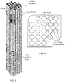
- a cross-sectional view of a fuel assembly is shown in figure 4 where some of the sub-channels are indicated.
- the present invention relates to a first computer-implemented simulation method of predicting local concentrations of constituents in coolant water anywhere along fuel rods within any fuel assembly mechanical design of a Boiling Water Reactor (BWR) potentially resulting in crud deposits on said fuel rods.
- BWR Boiling Water Reactor
- the method is based on a sub-channel approach of predicting local mass fluxes of vapour and liquid in coolant water anywhere along fuel rods within any fuel assembly mechanical design of a Boiling Water Reactor (BWR) for given steady-state or transient boundary conditions.
- the sub-channel approach is based on the solution of mass, momentum and energy conservation equations for the vapour phase and the liquid phase, where the liquid phase is represented by more than one field variable, and is specifically represented by three fields, with the vapour phase as a fourth field, consisting of droplets, a liquid base film, and disturbance waves.
- the method comprises solving individual mass, momentum and energy conservation equations, for the four fields, and solving the necessary closure relations describing the transfer of mass between the said fields, completed by mass conservation equations for constituents dissolved in the liquid phase and transported by each of the said fields individually.
- the method comprises:
- the calculation is made for each fuel rod of the fuel assembly and includes thermal-hydraulics couplings between sub-channels.
- the method further comprises comparing said calculated local instantaneous impurity concentration to a crud compound precipitation limit, and during the time said concentration is higher than said precipitation limit, crud is considered to have occurred.
- Figure 6 shows a graph illustrating how impurity concentration varies between passing disturbance waves.
- Figure 3 illustrates a fuel assembly comprising fuel rods.
- the different grey colours indicate how much impurity concentration is present, where black indicates highest concentration.
- a so-called part length rod is also indicated.
- the method step of analysing predefined parameters of disturbance waves includes resolving the mass and momentum conservation equations in every considered sub-channels using a four-field approach where the waves and base films are considered separately (also referred as disturbance wave model).
- This model is coupled to a sub-channel analysis code for the crossflow calculations and some elements of the momentum balance (such as pressure gradient and inertia terms) may be neglected.
- the method comprises applying impurity mass conservation equations consistent with the four-field conservation equations mentioned above. Based upon the interaction between the waves and liquid base film, the model calculates a detailed distribution of impurity concentrations axially and azimuthally (i.e. along the perimeter of a given fuel rod) within each liquid base film flowing along the fuel rods of the fuel assembly under operating conditions of interest.
- the method further comprises applying a local instantaneous impurity concentration model, which is used as a post-process of the base film impurity concentration model, and, for each fuel rod, being configured to calculate said local instantaneous impurity concentration within the slowly moving liquid base film in between disturbance waves during nominal operation and any transients, such as predetermined inlet flow velocity variations.
- a local instantaneous impurity concentration model which is used as a post-process of the base film impurity concentration model, and, for each fuel rod, being configured to calculate said local instantaneous impurity concentration within the slowly moving liquid base film in between disturbance waves during nominal operation and any transients, such as predetermined inlet flow velocity variations.
- the method further comprises simulating operating conditions of interest by varying the fissile material content (e.g. the 235 U enrichment) of one or several fuel pellets of one or several fuel rods in dependence of the calculated local instantaneous impurity concentration in order to prevent the formation of crud deposits.
- the fissile material content e.g. the 235 U enrichment
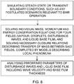
- the present invention also relates to a second computer-implemented simulation method, which is schematically illustrated by the flow diagram shown in figure 8 .
- the second simulation method is based on a sub-channel approach of predicting local mass fluxes of vapour and liquid in coolant water anywhere along fuel rods within any fuel assembly mechanical design of a Boiling Water Reactor (BWR) for given steady-state or transient boundary conditions.
- the sub-channel approach is based on the solution of mass, momentum and energy conservation equations for the vapour phase and the liquid phase, the liquid phase is represented by more than one field variable, and is specifically represented by three fields, with the vapour phase as a fourth field, consisting of droplets, a liquid base film, and disturbance waves.
- the method comprises solving individual mass, momentum and energy conservation equations, for said four fields, and solving the necessary closure relations describing the transfer of mass between the said fields, completed by models describing local phenomena.
- the method further comprises:
- the method step of analysing predefined parameters comprises analysing liquid base film between consecutive passing disturbance waves, to calculate, for each fuel rod of the fuel assembly, local instantaneous dry patch formation and associated clad temperature increase in between disturbance waves during said simulated steady-state or transient operations.
- the method step of analysing predefined parameters comprises analysing liquid disturbance wave characteristics, to calculate, for each fuel rod of the fuel assembly, droplet entrainment from the waves during said simulated steady-state or transient operations.
- the boundary conditions include input parameters having predetermined temporal variations.
- the local phenomena are base film dryout, clad temperature increase, and/or drop entrainment from waves.
- the second simulation method could be applied to any steady-state, transients and postulated scenarios relevant to BWR operation with respect to the potential appearance and rewetting of dry patches (between waves), associated dry time and clad temperature increase.
- the appearance of dry patches is derived from a local, instantaneous, consideration of the liquid base film during the time between two consecutive disturbance waves, including exchange terms with the steam and drop fields.
- the second method could be further extended to calculate the amount of droplet entrained from the liquid film. The droplet entrainment is closely related to the wave characteristics and can be calculated from the consideration of wave geometrical dimensions, mass and momentum derived from the four-field approach.
- the present invention also relates to a Boiling Water Reactor (BWR) comprising fuel assemblies including fuel rods provided with fuel pellets having a 235 U enrichment level.
- BWR Boiling Water Reactor
- the enrichment level is determined in dependence of the result of simulations performed by the above described simulation methods.
- the simulation method may be applied to determine enrichment levels required to make the next-to-corner rods equally susceptible to crud deposition as all other rods in the fuel assembly.
- a 235 U optimization involving the local concentration of crud constituents, may be reached in the nuclear design process, in a similar manner as already existing design criteria.
- the present invention is based upon new advanced features and is implemented by two newly-developed models, a disturbance wave model, and an impurity concentration model.
- the disturbance wave model applies a ID, two-phase, four-field approach.
- the fields of a commonly applied three-field approach comprise steam, liquid droplets, and a liquid film.
- the liquid film is further divided into liquid disturbance waves and a liquid base film.
- the four fields are steam, liquid droplets, liquid disturbance waves and a liquid base film. This is schematically illustrated in figure 1 . Because of the mass, momentum and energy exchanges between disturbance waves and base film, there is a need for new constitutive models and field exchange terms.
- the impurity concentration model is calculated in all considered fields by applying additional impurity conservation equations for all fields. This is similar to the mass conservation equations already utilized in the sub-channel code, but with different exchanges between fields (since impurities are not transported to the steam field).
- the disturbance wave model is based upon the following assumptions and is illustrated by figure 2 .
- the four fields comprise very fast moving steam, liquid droplets, fast moving waves that tend to be coherent and transport most of the film mass, and a slow moving liquid base film that is very thin and contributes much less to the liquid film mass transport.
- the left-hand side of the equation represents the inertia terms and the right-hand side of the equation represents (in order), the momentum transported by drop deposition, entrainment, evaporation and crossflow, the pressure gradient, the gravity and the interfacial forces (from vapour and wall).
- constitutive models e.g. for the interfacial forces between fields in particular: wave drag force, and the wave to base film force.
- These constitutive modes can be based on physical considerations or empirical correlations (when a suitable experimental database is available).
- Additional inputs are also required to sufficiently describe the average wave and base film geometrical characteristics locally. While the choices may differ depending on the method, these inputs would typically include the wave amplitude ( h w ), width ( l w ), and base liquid film thickness ( h b ). These may also be obtained by physical considerations and/or calibrated empirical correlations (when a suitable experimental database is available).
- the equations are then solved for wave mass flow and wave velocities.
- the wave frequency is determined from consistency with the wave mass and momentum conservation equations.
- the Reynolds number (Re) is an important dimensionless quantity in fluid mechanics typically used to help predict flow patterns in different fluid flow situations. At low Reynolds numbers, flows tend to be dominated by laminar (sheet-like) flow, while at high Reynolds numbers turbulence results from differences in the speed and direction of the fluid.
- model relaxations are applied in the model to allow the geometrical characteristics of the waves to smoothly transition from one state to the other.
- the relaxations characterizes the rate at which the wave can exchange mass with the base film and the rate at which the wave characteristics can change, consistent with experimental observations.
- the model is implemented in MEFISTO-T and the wave and base film geometrical characteristic correlations are calibrated against the RISO database. It has been tested for simple flow transients such as Fukano transients.
- the RISO database is a publicly available high-pressure steam/water database made available by the Department of Reactor Technology at the Riso National laboratory, Denmark, in 1978. Wurtz, J. (1978).
- An experimental and theoretical investigation of annular steam-water flow in tubes and annuli at 30 to 90 bar. (Denmark. Forskningscenter Risoe. Risoe-R; No. 372 ). Measurements were presented of film flow rates, pressure gradients, film thicknesses, wave frequencies and velocities, and burnout (dryout) heat fluxes in one annular and two tubular geometries. The more than 250 experiments were performed with steam-water at 30 to 90 bar under both adiabatic and diabatic conditions.
- the impurity concentration model will now be described using the concept of impurity mass conservation in all fields.
- the steam is created through an evaporation process and is not considered to transport any impurity.
- An example of impurity concentration calculation is provided, applicable to the three-field approach
- the local, instantaneous, concentration in the base film between waves is calculated by using input parameters ( ⁇ t , ⁇ 0 , C 0 ) from the four-field approach.
- input parameters ⁇ t , ⁇ 0 , C 0
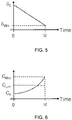
- figures 5 and 6 the base film thickness, and the base film concentration are illustrated, respectively.
- Figure 5 shows how the base film thickness varies over time at a specified location in between disturbance waves.
- the line defining the base film thickness variation is mainly governed by the evaporation process.
- C Lim plant-specific information is required.
- C Inlet 15.6 ppb
- C LIM 10 ⁇ C Inlet .
- Solubility limits are used as thresholds to translate local concentrations in fuel rod coolant film into a crud deposition mass flux.
- the crud depositions may thereby be modelled as a simple threshold phenomenon.
- the new modelling capability can accurately predict the relative levels of local film concentration and crud deposition mass flux axially and azimuthally on the different rods, without significantly relying on modelling assumptions.
- the model has been validated against inspection data from an operating BWR.
- the key parameters affecting the margin to crud deposition are: Local heat flux; local wave frequency; local base film thickness, and constituents' bulk concentration.
- the first three parameters can be controlled by optimizing nuclear design, i.e. by optimizing the axial enrichment variation in the rods predicted to be most susceptible to crud.
Landscapes
- Engineering & Computer Science (AREA)
- Physics & Mathematics (AREA)
- General Engineering & Computer Science (AREA)
- Plasma & Fusion (AREA)
- High Energy & Nuclear Physics (AREA)
- Monitoring And Testing Of Nuclear Reactors (AREA)
- Theoretical Computer Science (AREA)
- General Physics & Mathematics (AREA)
- Computing Systems (AREA)
- Fluid Mechanics (AREA)
- Algebra (AREA)
- Mathematical Analysis (AREA)
- Mathematical Optimization (AREA)
- Mathematical Physics (AREA)
- Pure & Applied Mathematics (AREA)
- Computer Hardware Design (AREA)
- Evolutionary Computation (AREA)
- Geometry (AREA)
- Management, Administration, Business Operations System, And Electronic Commerce (AREA)
Abstract
Description
- The present disclosure relates to methods for nuclear reactors, and specifically to Boiling Water Reactors (BWR), intended to characterize disturbance waves and base film in coolant water, and specifically to one method adapted to predict crud depositions of relatively high solubility compounds, such as ZnO and Zn2SiO4, in fuel assemblies, in the annular two-phase flow regime, in particular when induced by transients such as inlet flow fluctuations in BWR fuel assemblies.
- In the upper level of fuel assemblies in BWR:s, very dense crud deposits have been recently observed. Crud is a colloquial term for corrosion and wear products (rust particles, etc.) where part of it becomes radioactive (i.e. activated) when exposed to radiation. Mechanisms leading to crud deposition can also potentially lead to fuel performance issues such as spalling, reduced thermal conductivity and even fuel failures and this hence can become a safety concern. The dense crud deposits in the upper level of fuel assemblies were observed in specific fuel assembly locations, and there was no previous experience of this dense crud in earlier cycles or in other, similar, plants.
- Thus, the object of the present invention is to achieve a method of simulating and predicting impurity concentration in the annular two-phase flow regime and margin to associated crud deposition threshold in BWR fuel assemblies.
- A more general object is to achieve a method of simulating and predicting local mass fluxes and local characteristics of disturbance waves and base film in coolant water of BWR fuel assemblies.
- A further object is to design a BWR fuel assembly comprising fuel rods with fuel pellets having enrichment levels determined in dependence of the result of the simulation method in order to avoid crud.
- The above-mentioned objects are achieved by the present invention according to the independent claims.
- Preferred embodiments are set forth in the dependent claims.
- According to a first aspect, the present invention relates to a computer-implemented simulation method of predicting local concentrations of any impurity constituents in coolant water anywhere along fuel rods within any fuel assembly mechanical design of a Boiling Water Reactor (BWR) potentially resulting in crud deposits on said fuel rods. The simulation method is based on a sub-channel approach of predicting local mass fluxes of vapour and liquid in coolant water anywhere along fuel rods within any fuel assembly mechanical design of a Boiling Water Reactor (BWR) for given steady-state or transient boundary conditions. The sub-channel approach is based on the solution of mass, momentum and energy conservation equations for the vapour phase and the liquid phase. The liquid phase is represented by more than one field variable, and is specifically represented by three fields, with the vapour phase as a fourth field, consisting of droplets, a liquid base film, and disturbance waves. The method comprises solving individual mass, momentum and energy conservation equations, for said four fields, and solving the necessary closure relations describing the transfer of mass between the said fields, completed by mass conservation equations for constituents dissolved in the liquid phase and transported by each of the said fields individually. The method further comprises:
- Simulating steady-state or transient boundary conditions, such as inlet coolant water flow into said fuel assembly. In case of transient simulations, the boundary conditions include input parameters that have predetermined temporal variations.
- Analysing predefined parameters of said disturbance waves and liquid base film, including wave velocity and frequency, and base film thickness.
- Analysing liquid base film between consecutive passing disturbance waves, to calculate local instantaneous impurity concentrations in between disturbance waves during said simulated steady-state or transient operations.
- The calculations are made for each fuel rod of the fuel assembly, wherein, for each fuel rod, the method further comprises comparing the calculated local instantaneous impurity concentration to a crud compound precipitation limit, and during the time said concentration is higher than said precipitation limit, crud deposition is considered to have occurred.
- According to a second aspect, the present invention relates to a computer-implemented simulation method. The method is based on a sub-channel approach of predicting local mass fluxes of vapour and liquid in coolant water anywhere along fuel rods within any fuel assembly mechanical design of a Boiling Water Reactor (BWR) for given steady-state or transient boundary conditions. The sub-channel approach is based on the solution of mass, momentum and energy conservation equations for the vapour phase and the liquid phase. The liquid phase is represented by more than one field variable, and is specifically represented by three fields, with the vapour phase as a fourth field, consisting of droplets, a liquid base film, and disturbance waves. The method comprises solving individual mass, momentum and energy conservation equations, for said four fields, and solving the necessary closure relations describing the transfer of mass between the said fields, completed by models describing local phenomena such as base film dryout, clad temperature increase or drop entrainment from waves. The method comprises:
- Simulating steady-state or transient boundary conditions, such as any postulated scenarios relevant to BWR operation. In case of transient simulations, the boundary conditions include input parameters that have predetermined temporal variations.
- Analysing predefined parameters of said disturbance waves and liquid base film, including wave velocity and frequency, and base film thickness.
- In one embodiment, the step of analysing predefined parameters comprises analysing liquid base film between consecutive passing disturbance waves, to calculate local instantaneous dry patch formation and associated clad temperature increase in between disturbance waves during said simulated steady-state or transient operations. The calculations are made for each fuel rod of the fuel assembly.
- In another embodiment, the step of analysing predefined parameters comprises analysing liquid disturbance wave characteristics, to calculate droplet entrainment from the waves during said simulated steady-state or transient operations. The calculations are made for each fuel rod of the fuel assembly.
- According to a third aspect, the present invention relates to a Boiling Water Reactor (BWR) comprising fuel assemblies including fuel rods provided with fuel pellets having a 235U enrichment level. The enrichment level is determined in dependence of the result of simulations performed by the simulation methods defined above, in particular such that crud deposition does not occur under pre-determined boundary conditions.
- The present invention is based upon an extensive root cause analysis where it has been established that the crud deposition problem is related to significant fluctuations of fuel assembly inlet coolant water flow. It is also established that the fluctuations have caused thermal-hydraulic propagation through the assembly resulting in enhanced impurity concentration above certain precipitation limits in particular fuel assembly locations. These new phenomena have never been directly addressed before.
- The method according to the first aspect of the present invention provides a strategy to solve the problem of crud deposition.
- Thus, the purpose of the strategy is to evaluate the risk of crud depositions. There is presently no tool available for taking into account the influence of disturbance waves, in particular under conditions of fast fluctuations in fuel assembly inlet flow. It is suggested to apply the above described method, which is consistent with the root cause analysis, and allows to reduce the risk of crud depositions by modifying the nuclear design, e.g. by modifying the amount of fissile material in the fuel (e.g. the 235U enrichment) utilized at specified positions of individual fuel rods. Other means of controlling the risk of crud depositions are limiting the power produced by each fuel assembly (by adjusting the core loading pattern, e.g. loading more fresh fuel assemblies), reducing the total core power or reducing reactor water impurity concentrations at the inlet to the fuel assemblies (e.g. by injecting less zinc). Adjusting 235U enrichment is, however, the preferred approach since it has minimum impact on reactor operation and/or fuel economy.
- A new computational tool is thereby developed, which is based on well-known thermal-hydraulic models for BWR fuel. These well-known models are extended with new physical models which include the four-field approach and potential simplifying assumptions.
- Some of the well-known computational tools for thermal-hydraulics for BWR fuel analysis comprise:
- Reactor physics codes (e.g. POLCA; Westinghouse's state-of-the-art code for BWR core design and safety analysis) using 1-D per assembly, which is not adequate herein due to the global approach, as no thermal-hydraulics differences between individual fuel rods are considered in these core design codes.
- Sub-channel analysis codes (e.g. MEFISTO-T; Westinghouse's transient three-field sub-channel analysis code) using 1-D at the sub-channel level. These thermal-hydraulics sub-channel analysis codes are adequate herein, as they apply a local approach.
- Computational Fluid Dynamics (CFD) codes being increasingly used in nuclear reactor safety analyses as a tool that enables safety relevant phenomena occurring in the reactor coolant system. CFD codes provide full (high-resolution) 3-D, but are not adequate herein because of limited state-of-the-art for BWR fuel applications.
- In thermal-hydraulic analyses, the term sub-channel is conventionally defined by the space in-between fuel rods in a fuel assembly. Often the space between three or four neighbouring fuel rods define a sub-channel. Boundary conditions (such as inlet coolant water flow) is applied into each so defined sub-channels. Also, the interactions between sub-channels are taken into account.
- Furthermore, the thermal-hydraulics of BWR fuel assembly is simulated by the code, where a basic assumption is that coolant water transports heat away from the core. The coolant water is subcooled at the inlet and typically has an annular two-phase (steam and liquid) flow at the outlet.
- In a standard sub-channel analysis approach, a ID, two-phase, three-field approach is applied. The three-field approach comprises analysing steam, liquid droplets, and liquid film by applying separate conservation equations for all fields, which includes mass, momentum and energy exchanges between the fields. Mass, momentum and energy exchanges between sub-channels are also calculated in order to simulate the radial interactions across the fuel lattice.
- The above may be calculated by applying state-of-the-art models, which are well documented in publicly available disclosures, and e.g. implemented in above-mentioned Westinghouse code MEFISTO-T, or in several other codes from the industry and academia (e.g. COBRA-TF).
- According to the first aspect of the present invention, a set of models is defined to address the crud deposition problem, and these models are based upon further development of the above-mentioned state-of-the-art models.
- A disturbance wave model is thereby developed, and implemented, based on an extension of the three-field model into a four-field model in a sub-channel analysis code, to enable the computation of the detailed distribution of impurity concentration within each liquid base film flowing along the rods of the fuel assembly under operating conditions of interest, e.g. pressure, flow, power, fuel rod power distribution, including during transient operation.
- A local instantaneous impurity model is also further developed and added to the first model to calculate the local instantaneous impurity concentration within the base liquid film in between disturbance waves during steady-state and transient operation, such as inlet flow fluctuations. During the time in which the local instantaneous impurity concentration is higher than a predetermined crud compound precipitation limit, crud deposition is considered to occur.
- The above two models are based on physical phenomena consistent with the performed root cause analysis.
- This new tool is used to avoid undesired crud deposition in BWR fuel assemblies in annular two-phase flow under expected plant operating conditions by locally adjusting the rod power (via 235U enrichment) for any lattice geometry.
-
-
Figure 1 is a schematic illustration of a cross-section steam/liquid annular two-phase flow along a fuel rod. -
Figure 2 is a schematic illustration of a cross-section steam/liquid annular two-phase flow along a fuel rod illustrating some aspects of the present invention. -
Figure 3 is a schematic perspective view of a fuel assembly where the method according to the present invention is applied. -
Figure 4 is a schematic cross-sectional view of a fuel assembly, which include the representation of various sub-channels. -
Figures 5 and 6 show graphs illustrating results of the local instantaneous impurity concentration simulation. -
Figure 7 is a flow diagram illustrating a method according to a first aspect of the present invention. -
Figure 8 is a flow diagram illustrating a method according to a second aspect of the present invention. - The computer-based simulation methods will now be described in detail with references to the appended figures. Throughout the figures the same, or similar, items have the same reference signs. Moreover, the items and the figures are not necessarily to scale, emphasis instead being placed upon illustrating the principles of the invention.
- Initially, a background of available calculation tools and models will be given.
- Modelling and validation of two-phase with three-field sub-channel analysis codes (e.g. MEFISTO-T) for the prediction of two-phase flow, up to critical power where so-called dryout occurs, in BWR fuel assemblies is previously known, and publicly available, and has been developed and applied by the applicant.
- Westinghouse has developed the MEFISTO-T code with the main goal to achieve fast, robust, practical and reliable predictions of steady-state and transient dryout power in Boiling Water Reactor (BWR) fuel assemblies based on a mechanistic approach. A computationally efficient simulation scheme is used to achieve this goal, where the code resolves all relevant field (drop, steam and multi-film) mass balance equations, within the annular flow region, at the sub-channel level while relying on a fast and robust two-phase (liquid/steam) sub-channel solution to provide the cross-flow information. The MEFISTO-T code can hence provide highly detailed solutions of the multi-film flow in BWR fuel assemblies while enhancing flexibility and reducing the computer time by an order of magnitude as compared to a standard three-field sub-channel analysis approach. Models for the numerical computation of the one-dimensional field flowrate distributions in an open channel (i.e. a sub-channel), including the numerical treatment of field cross-flows, part-length rods, spacers grids and post-dryout conditions are included in the code. The MEFISTO-T code is then applied to dryout predictions in BWR fuel assemblies using the VIPRE-W code as a fast and robust two-phase sub-channel driver code. The dryout power is numerically predicted by iterating on the assembly power so that the minimum film flowrate in the assembly reaches the predetermined dryout criteria. Predicted dryout powers (including trends with flow, pressure, inlet subcooling conditions and power distribution) and predicted dryout locations (both axial and radial) are compared to experimental results, using available dryout databases, and are shown to yield excellent results.
- The MEFISTO-T code applied to dryout predications is discussed e.g. in "Modeling and validation of a mechanistic tool (MEFISTO) for the prediction of critical power in BWR fuel assemblies" by Adamsson, Carl; Le Corre, Jean-Marie, published 2011 in "Nuclear Engineering and Design"; ISSN 0029-5493; Worldcat; CODEN NEDEAU; v. 241(8); p. 2843-2858.
- The MEFISTO-T code is based on a simplified approach to sub-channel film-flow analysis whereby the sub-channel transport equations for the liquid films are decoupled from each other. The approach allows fast and robust simulation with high axial resolution of BWR steady-state operation and realistic transients. The code has been successfully validated against experimental data under both steady state conditions and transient conditions involving realistic variations of flow and power and three different axial power distributions, at conditions typical during BWR operation.
- Semi-empirical dryout correlations are commonly used to predict the dryout power in BWR fuel rod assemblies under both steady-state and transient conditions. Even though these correlations can be based on mechanistic features, they are still essentially empirical and require the use of an extensive and fuel-specific critical power database to be developed. By contrast, mechanistic methods based on sub-channel annular two-phase flow modelling, such as in MEFISTO-T code, have the potential for accurate dryout prediction capabilities outside the correlation development database.
- To summarize, MEFISTO-T is a sub-channel analysis code developed at Westinghouse with the main purpose to predict film flow distributions on every fuel rod during steady-state and transient operations. The code is based on a one-dimensional three-field approach where liquid film, liquid droplets and vapour are considered in every sub-channel. MEFISTO-T relies on a simplified two-phase flow model (VIPREW) to calculate the time-dependent distribution of flow and enthalpy in every sub-channel, before applying the three-field approach from onset of annular flow to assembly outlet, in all or selected sub-channels.
- Generally, the simulation methods according to the present invention comprise extending the three-field approach to a four-field approach, wherein the liquid film on each fuel rod in the four-field approach is divided into fast moving disturbance waves on top of slowly moving liquid base films. This is schematically illustrated in
figures 1 and 2 . The simulation methods are based upon a sub-channel mechanistic model using a transient three-field (steam, liquid drops, liquid film) approach including couplings between sub-channels defined between said fuel rods. This mechanistic model is e.g. the above-discussed MEFISTO-T code. A cross-sectional view of a fuel assembly is shown infigure 4 where some of the sub-channels are indicated. - The present invention relates to a first computer-implemented simulation method of predicting local concentrations of constituents in coolant water anywhere along fuel rods within any fuel assembly mechanical design of a Boiling Water Reactor (BWR) potentially resulting in crud deposits on said fuel rods. The first method will now be described in detail, and in particular with references to the flow diagram shown in
figure 7 . - The method is based on a sub-channel approach of predicting local mass fluxes of vapour and liquid in coolant water anywhere along fuel rods within any fuel assembly mechanical design of a Boiling Water Reactor (BWR) for given steady-state or transient boundary conditions. The sub-channel approach is based on the solution of mass, momentum and energy conservation equations for the vapour phase and the liquid phase, where the liquid phase is represented by more than one field variable, and is specifically represented by three fields, with the vapour phase as a fourth field, consisting of droplets, a liquid base film, and disturbance waves.
- The method comprises solving individual mass, momentum and energy conservation equations, for the four fields, and solving the necessary closure relations describing the transfer of mass between the said fields, completed by mass conservation equations for constituents dissolved in the liquid phase and transported by each of the said fields individually.
- The method comprises:
- Simulating steady-state or transient boundary conditions for the condition of interest to the fuel assembly, such as inlet coolant water flow into said sub-channels (the coolant water flow may have a predetermined flow velocity variation), temperature, pressure, rod power distribution, and assembly power.
- Analysing predefined parameters of said disturbance waves and base film, including wave velocity and frequency, base film thickness, etc. based upon the interaction between the disturbance waves, the liquid base film, the liquid drops and the vapor.
- Analysing liquid base film thickness between consecutive passing disturbance waves, to calculate local instantaneous impurity concentrations based on said simulated boundary conditions.
- The calculation is made for each fuel rod of the fuel assembly and includes thermal-hydraulics couplings between sub-channels. For each fuel rod, the method further comprises comparing said calculated local instantaneous impurity concentration to a crud compound precipitation limit, and during the time said concentration is higher than said precipitation limit, crud is considered to have occurred.
-
Figure 6 shows a graph illustrating how impurity concentration varies between passing disturbance waves. -
Figure 3 illustrates a fuel assembly comprising fuel rods. In the figure is indicated portions of two fuel rods where high impurity concentration has been identified. The different grey colours indicate how much impurity concentration is present, where black indicates highest concentration. In the figure, a so-called part length rod is also indicated. - According to one embodiment, the method step of analysing predefined parameters of disturbance waves includes resolving the mass and momentum conservation equations in every considered sub-channels using a four-field approach where the waves and base films are considered separately (also referred as disturbance wave model). This model is coupled to a sub-channel analysis code for the crossflow calculations and some elements of the momentum balance (such as pressure gradient and inertia terms) may be neglected.
- According to another embodiment, the method comprises applying impurity mass conservation equations consistent with the four-field conservation equations mentioned above. Based upon the interaction between the waves and liquid base film, the model calculates a detailed distribution of impurity concentrations axially and azimuthally (i.e. along the perimeter of a given fuel rod) within each liquid base film flowing along the fuel rods of the fuel assembly under operating conditions of interest.
- According to still another embodiment, the method further comprises applying a local instantaneous impurity concentration model, which is used as a post-process of the base film impurity concentration model, and, for each fuel rod, being configured to calculate said local instantaneous impurity concentration within the slowly moving liquid base film in between disturbance waves during nominal operation and any transients, such as predetermined inlet flow velocity variations.
- According to another embodiment, the method further comprises simulating operating conditions of interest by varying the fissile material content (e.g. the 235U enrichment) of one or several fuel pellets of one or several fuel rods in dependence of the calculated local instantaneous impurity concentration in order to prevent the formation of crud deposits.
- The present invention also relates to a second computer-implemented simulation method, which is schematically illustrated by the flow diagram shown in
figure 8 . - The second simulation method is based on a sub-channel approach of predicting local mass fluxes of vapour and liquid in coolant water anywhere along fuel rods within any fuel assembly mechanical design of a Boiling Water Reactor (BWR) for given steady-state or transient boundary conditions. The sub-channel approach is based on the solution of mass, momentum and energy conservation equations for the vapour phase and the liquid phase, the liquid phase is represented by more than one field variable, and is specifically represented by three fields, with the vapour phase as a fourth field, consisting of droplets, a liquid base film, and disturbance waves.
- The method comprises solving individual mass, momentum and energy conservation equations, for said four fields, and solving the necessary closure relations describing the transfer of mass between the said fields, completed by models describing local phenomena. The method further comprises:
- Simulating steady-state or transient boundary conditions, such as any postulated scenarios relevant to BWR operation.
- Analysing predefined parameters of said disturbance waves and liquid base film, including wave velocity and frequency, and base film thickness.
- In one embodiment, the method step of analysing predefined parameters comprises analysing liquid base film between consecutive passing disturbance waves, to calculate, for each fuel rod of the fuel assembly, local instantaneous dry patch formation and associated clad temperature increase in between disturbance waves during said simulated steady-state or transient operations.
- In another embodiment, the method step of analysing predefined parameters comprises analysing liquid disturbance wave characteristics, to calculate, for each fuel rod of the fuel assembly, droplet entrainment from the waves during said simulated steady-state or transient operations.
- According to still another embodiment, in case of simulating transient boundary conditions, the boundary conditions include input parameters having predetermined temporal variations.
- Preferably, the local phenomena are base film dryout, clad temperature increase, and/or drop entrainment from waves.
- Thus, the second simulation method could be applied to any steady-state, transients and postulated scenarios relevant to BWR operation with respect to the potential appearance and rewetting of dry patches (between waves), associated dry time and clad temperature increase. The appearance of dry patches is derived from a local, instantaneous, consideration of the liquid base film during the time between two consecutive disturbance waves, including exchange terms with the steam and drop fields. In addition, the second method could be further extended to calculate the amount of droplet entrained from the liquid film. The droplet entrainment is closely related to the wave characteristics and can be calculated from the consideration of wave geometrical dimensions, mass and momentum derived from the four-field approach.
- The present invention also relates to a Boiling Water Reactor (BWR) comprising fuel assemblies including fuel rods provided with fuel pellets having a 235U enrichment level. The enrichment level is determined in dependence of the result of simulations performed by the above described simulation methods.
- For example, the simulation method may be applied to determine enrichment levels required to make the next-to-corner rods equally susceptible to crud deposition as all other rods in the fuel assembly.
By generally applying the present invention, a 235U optimization, involving the local concentration of crud constituents, may be reached in the nuclear design process, in a similar manner as already existing design criteria. - As discussed above, the present invention is based upon new advanced features and is implemented by two newly-developed models, a disturbance wave model, and an impurity concentration model.
- The disturbance wave model applies a ID, two-phase, four-field approach. The fields of a commonly applied three-field approach comprise steam, liquid droplets, and a liquid film. In the four-field approach, the liquid film is further divided into liquid disturbance waves and a liquid base film. Thus, the four fields are steam, liquid droplets, liquid disturbance waves and a liquid base film. This is schematically illustrated in
figure 1 .
Because of the mass, momentum and energy exchanges between disturbance waves and base film, there is a need for new constitutive models and field exchange terms. - The impurity concentration model is calculated in all considered fields by applying additional impurity conservation equations for all fields. This is similar to the mass conservation equations already utilized in the sub-channel code, but with different exchanges between fields (since impurities are not transported to the steam field).
- These newly developed models will now be discussed more in detail.
- The disturbance wave model is based upon the following assumptions and is illustrated by
figure 2 . - The four fields comprise very fast moving steam, liquid droplets, fast moving waves that tend to be coherent and transport most of the film mass, and a slow moving liquid base film that is very thin and contributes much less to the liquid film mass transport.
- Transient field conservation equations are resolved, and below is one example of a liquid film momentum balance equation in a three-field approach:

- The left-hand side of the equation represents the inertia terms and the right-hand side of the equation represents (in order), the momentum transported by drop deposition, entrainment, evaporation and crossflow, the pressure gradient, the gravity and the interfacial forces (from vapour and wall).
- Following the same approach in the new four-field formulation, with reference to
figure 2 , where various parameters are shown, it is possible to establish an equation representing wave momentum conservation and base film momentum conservation. The wave momentum conservation is written below:
- In practice, some simplifications can be made whenever justified. For instance, in the specific case where steam/drop/wave/base film momentum transfer from mass exchanges, pressure gradient and inertia terms can be neglected, we get:

- Below is a list showing what the parameters of the above equations stand for:
- W: Mass flowrate
- w: Mass flowrate in crossflow
- u: Velocity
- D: Drop deposition mass flux (to film)
- E: Drop entrainment mass flux (from film)
- Γ: Evaporation mass flux (from film)
- Ψ: Wave/base film mass flux
- Π: Wall perimeter
- p: Pressure
- ρ: Density
- h: Thickness
- τ: Interfacial force (per unit area)
- t: Time
- z: Axial elevation
- w: wave
f: film
d: drop
l: liquid
v: vapor
b: base film - In
figure 2 , the resulting forces on the waves are schematically indicated by arrows in the simple case depicted by the previous equation. A force balance is achieved by gravity forces, steam drag and wave to base film momentum transfer ("friction").
- In order to complete the system of equations, it is required to have constitutive models, e.g. for the interfacial forces between fields in particular: wave drag force, and the wave to base film force. These constitutive modes can be based on physical considerations or empirical correlations (when a suitable experimental database is available).
- Additional inputs are also required to sufficiently describe the average wave and base film geometrical characteristics locally. While the choices may differ depending on the method, these inputs would typically include the wave amplitude (hw ), width (lw ), and base liquid film thickness (hb ). These may also be obtained by physical considerations and/or calibrated empirical correlations (when a suitable experimental database is available).
- The equations are then solved for wave mass flow and wave velocities. The wave frequency is determined from consistency with the wave mass and momentum conservation equations.
- Below is shown four examples of calibrated empirical correlations. Different correlations may be developed as more relevant data becomes available. These are determined by using data from publicly available experimental databases at relevant BWR core conditions. The correlations were derived using regression analysis, specifically performed for the four-field model. Regression analysis is a powerful statistical method that allows to examine the relationship between two or more variables of interest. While there are many types of regression analysis, at their core they all examine the influence of one or more independent variables on a dependent variable.
- Equilibrium base film thickness:

- Wave amplitude:

- Wave width:

- Wave drag coefficient:

- Below is a list showing what the parameters of the above equations stand for:
- hb: Base film thickness
- hw: Wave amplitude
- lw: Wave (axial) width
- Cw: Wave drag coefficient
- dH: Equivalent hydraulic diameter (4A/P)
- dA: Equivalent circular area diameter (sqrt(4A/π)
- Rev: Vapor Reynolds number (ρv ∗uv ∗dA/µv)
- Revw: Vapor Reynolds number with respect to wave velocity (ρv ∗(uv-uw)∗dA/|µv)
- Ref: Film Reynolds number (4∗Mf/Π/µf)
- Rew: Wave Reynolds number (4∗Mw/Π/µf)
- The Reynolds number (Re) is an important dimensionless quantity in fluid mechanics typically used to help predict flow patterns in different fluid flow situations. At low Reynolds numbers, flows tend to be dominated by laminar (sheet-like) flow, while at high Reynolds numbers turbulence results from differences in the speed and direction of the fluid.
- Because the calibrated correlations were derived from data under equilibrium conditions (thermal and mechanical), model relaxations are applied in the model to allow the geometrical characteristics of the waves to smoothly transition from one state to the other. The relaxations characterizes the rate at which the wave can exchange mass with the base film and the rate at which the wave characteristics can change, consistent with experimental observations.
- The model is implemented in MEFISTO-T and the wave and base film geometrical characteristic correlations are calibrated against the RISO database. It has been tested for simple flow transients such as Fukano transients.
- The RISO database is a publicly available high-pressure steam/water database made available by the Department of Reactor Technology at the Riso National laboratory, Denmark, in 1978. Wurtz, J. (1978). An experimental and theoretical investigation of annular steam-water flow in tubes and annuli at 30 to 90 bar. (Denmark. Forskningscenter Risoe. Risoe-R; No. 372).
Measurements were presented of film flow rates, pressure gradients, film thicknesses, wave frequencies and velocities, and burnout (dryout) heat fluxes in one annular and two tubular geometries. The more than 250 experiments were performed with steam-water at 30 to 90 bar under both adiabatic and diabatic conditions. - The transient experimental experiments performed by Fukano are available in T. Fukano, S. Mori, T. Nakagawa (2003). Fluctuation characteristics of heating surface temperature near an obstacle in transient boiling two-phase flow in a vertical annular channel. Nuclear Engineering and Design 219 (2003) 47-60.
In these low-pressure, steam-water tests in a heated annulus, fast variations in input power, inlet enthalpy and inlet flow were performed, while the dynamic behavior of the disturbance waves were visually observed near the test section outlet. Long suppression (delay) of disturbance waves could be observed under specific transients, associated with large wall temperature variations corresponding to the complete dryout of the base film in between disturbance waves. - The impurity concentration model will now be described using the concept of impurity mass conservation in all fields. The steam is created through an evaporation process and is not considered to transport any impurity.
An example of impurity concentration calculation is provided, applicable to the three-field approach - Film:

- Drop:

- Steam: No impurities considered.
- In the equations above C stands for impurity concentration, superscript CF stands for cross-flow between sub-channels, and subscript f and d stand for film and drop, respectively.
- The same concept applies to the four-field approach where the impurity concentration is written consistently with the mass conservation, including the mass exchange between the considered fields.
- In a second step, the local, instantaneous, concentration in the base film between waves is calculated by using input parameters (Δt, δ0 , C0 ) from the four-field approach. In
figures 5 and 6 the base film thickness, and the base film concentration are illustrated, respectively. -
Figure 5 shows how the base film thickness varies over time at a specified location in between disturbance waves. At t=0 (immediately after a wave), the base film thickness has its maximum value δ0 and at t=Δt (corresponding to the wave period) the thickness is at its minimum, δMin. The line defining the base film thickness variation is mainly governed by the evaporation process. - δ: Instantaneous base film thickness
Δ t: Wave period
Subscripts: 0: Initial; LIM: Limit of impurity precipitation -
Figure 6 shows how the base film concentration varies over time. At t=0, the concentration is at its minimum C0 and at t=Δt at its hypothetical maximum CMax (when precipitation is disregarded), mainly governed by the base film thinning. A concentration limit value CLim is determined to a value where crud deposition starts. - To determine the crud deposition limit value CLim, plant-specific information is required. According to one example CInlet=15.6 ppb, and CLIM=10∗CInlet.
- Solubility limits are used as thresholds to translate local concentrations in fuel rod coolant film into a crud deposition mass flux. The crud depositions may thereby be modelled as a simple threshold phenomenon. Using a sub-channel analysis approach, the new modelling capability can accurately predict the relative levels of local film concentration and crud deposition mass flux axially and azimuthally on the different rods, without significantly relying on modelling assumptions.
- The model has been validated against inspection data from an operating BWR.
The key parameters affecting the margin to crud deposition are:
Local heat flux; local wave frequency; local base film thickness, and constituents' bulk concentration. The first three parameters can be controlled by optimizing nuclear design, i.e. by optimizing the axial enrichment variation in the rods predicted to be most susceptible to crud. - The present invention is not limited to the above-described preferred embodiments. Various alternatives, modifications and equivalents may be used. Therefore, the above embodiments should not be taken as limiting the scope of the invention, which is defined by the appending claims.
Claims (13)
- A computer-implemented simulation method of predicting local concentrations of constituents in coolant water anywhere along fuel rods within any fuel assembly mechanical design of a Boiling Water Reactor (BWR) potentially resulting in crud deposits on said fuel rods, the method is based on a sub-channel approach of predicting local mass fluxes of vapour and liquid in coolant water anywhere along fuel rods within any fuel assembly mechanical design of a Boiling Water Reactor (BWR) for given steady-state or transient boundary conditions, the sub-channel approach is based on the solution of mass, momentum and energy conservation equations for the vapour phase and the liquid phase, the liquid phase is represented by more than one field variable, and is specifically represented by three fields, with the vapour phase as a fourth field, consisting of droplets, a liquid base film, and disturbance waves, wherein the method comprises solving individual mass, momentum and energy conservation equations, for said four fields, and solving the necessary closure relations describing the transfer of mass between the said fields, completed by mass conservation equations for constituents dissolved in the liquid phase and transported by each of the said fields individually, and wherein the method comprises:- simulating steady-state or transient boundary conditions, such as inlet coolant water flow into said sub-channels, the coolant water flow may have a predetermined flow velocity variation,- analysing predefined parameters of said disturbance waves and base film, including wave velocity, wave frequency and base film thickness, and- analysing liquid base film thickness between consecutive passing disturbance waves, to calculate local instantaneous impurity concentrations based on said simulated boundary conditions, the calculation is made for each fuel rod of the fuel assembly, wherein, for each fuel rod, the method further comprises comparing said calculated local instantaneous impurity concentration to a crud compound precipitation limit, and during the time said concentration is higher than said precipitation limit, crud is considered to have occurred.
- The method according to claim 1, wherein said step of analysing predefined parameters of disturbance waves and said liquid base film includes resolving a disturbance wave momentum balance and a liquid base film momentum balance, and simplifying the calculations by neglecting momentum exchanges that have limited influence on the results (e.g. from pressure gradient and inertia terms).
- The method according to claim 1 or 2, further comprising applying a sub-channel disturbance wave model, and configured to, based upon the interaction between the waves and said liquid base film, calculate a detailed distribution of impurity concentrations axially and azimuthally (i.e. along the fuel rod's perimeter) within each liquid base film flowing along the fuel rods of the fuel assembly under operating conditions of interest, said operating conditions comprise pressure, flow velocity, power, fuel rod power distribution.
- The method according to claim 3, further comprising applying an impurity concentration model, which is used as a post-process of said disturbance wave model, and, for each fuel rod, being configured to calculate said local instantaneous impurity concentration within the slowly moving liquid base film in between disturbance waves during imposed operating conditions such as inlet flow velocity variations.
- The simulation method according to any of claims 1-4, further comprising simulating local concentration of crud constituents when varying enrichment of one or many fuel pellets of one or many fuel rods in order to reduce crud.
- A computer-implemented simulation method, based on a sub-channel approach of predicting local mass fluxes of vapour and liquid in coolant water anywhere along fuel rods within any fuel assembly mechanical design of a Boiling Water Reactor (BWR) for given steady-state or transient boundary conditions, the sub-channel approach is based on the solution of mass, momentum and energy conservation equations for the vapour phase and the liquid phase, the liquid phase is represented by more than one field variable, and is specifically represented by three fields, with the vapour phase as a fourth field, consisting of droplets, a liquid base film, and disturbance waves, the method comprises solving individual mass, momentum and energy conservation equations, for said four fields, and solving the necessary closure relations describing the transfer of mass between the said fields, completed by models describing local phenomena, wherein the method further comprises:- simulating steady-state or transient boundary conditions, such as any postulated scenarios relevant to BWR operation, and- analysing predefined parameters of said disturbance waves and liquid base film, including wave velocity and frequency, and base film thickness.
- The method according to claim 6, wherein analysing predefined parameters comprises analysing liquid base film between consecutive passing disturbance waves, to calculate local instantaneous dry patch formation and associated clad temperature increase in between disturbance waves during said simulated steady-state or transient operations, and wherein said calculations are made for each fuel rod of the fuel assembly.
- The method according to claim 6 or 7, wherein analysing predefined parameters comprises analysing liquid disturbance wave characteristics, to calculate droplet entrainment from the waves during said simulated steady-state or transient operations, and wherein said calculations are made for each fuel rod of the fuel assembly.
- The method according to any of claims 6-8, wherein in case of simulating transient boundary conditions, the boundary conditions include input parameters having predetermined temporal variations.
- The method according to any of claims 6-9, wherein said local phenomena is base film dryout.
- The method according to any of claims 6-10, wherein said local phenomena is clad temperature increase.
- The method according to claim 6-11, wherein said local phenomena is drop entrainment from waves.
- A Boiling Water Reactor (BWR) comprising fuel assemblies including fuel rods provided with fuel pellets having a fissile material concentration (i.e. an enrichment level), wherein said enrichment level is determined in dependence of the result of simulations performed by the simulation method according to any of claims 1-12.
Priority Applications (7)
| Application Number | Priority Date | Filing Date | Title |
|---|---|---|---|
| EP20169335.5A EP3896703B1 (en) | 2020-04-14 | 2020-04-14 | Method of providing bwr fuel pellets comprising determining u-235 enrichment levels determined by a computer-implemented simulation such that crud deposition does not occur under pre-determined boundary conditions |
| ES20169335T ES3022839T3 (en) | 2020-04-14 | 2020-04-14 | Method of providing bwr fuel pellets comprising determining u-235 enrichment levels determined by a computer-implemented simulation such that crud deposition does not occur under pre-determined boundary conditions |
| FIEP20169335.5T FI3896703T3 (en) | 2020-04-14 | 2020-04-14 | Method of providing bwr fuel pellets comprising determining u-235 enrichment levels determined by a computer-implemented simulation such that crud deposition does not occur under pre-determined boundary conditions |
| EP23178211.1A EP4235698A3 (en) | 2020-04-14 | 2020-04-14 | Computer-based simulation methods for boiling water reactors (bwr) |
| PCT/EP2021/057715 WO2021209237A1 (en) | 2020-04-14 | 2021-03-25 | Computer-based simulation methods for boiling water reactors (bwr) |
| US17/918,462 US20230142755A1 (en) | 2020-04-14 | 2021-03-25 | Computer-Based Simulation Methods for Boiling Water Reactors (BWR) |
| JP2022558452A JP7603079B2 (en) | 2020-04-14 | 2021-03-25 | Computer simulation method for boiling water reactor (BWR) |
Applications Claiming Priority (1)
| Application Number | Priority Date | Filing Date | Title |
|---|---|---|---|
| EP20169335.5A EP3896703B1 (en) | 2020-04-14 | 2020-04-14 | Method of providing bwr fuel pellets comprising determining u-235 enrichment levels determined by a computer-implemented simulation such that crud deposition does not occur under pre-determined boundary conditions |
Related Child Applications (2)
| Application Number | Title | Priority Date | Filing Date |
|---|---|---|---|
| EP23178211.1A Division EP4235698A3 (en) | 2020-04-14 | 2020-04-14 | Computer-based simulation methods for boiling water reactors (bwr) |
| EP23178211.1A Division-Into EP4235698A3 (en) | 2020-04-14 | 2020-04-14 | Computer-based simulation methods for boiling water reactors (bwr) |
Publications (2)
| Publication Number | Publication Date |
|---|---|
| EP3896703A1 true EP3896703A1 (en) | 2021-10-20 |
| EP3896703B1 EP3896703B1 (en) | 2025-03-12 |
Family
ID=70289351
Family Applications (2)
| Application Number | Title | Priority Date | Filing Date |
|---|---|---|---|
| EP23178211.1A Pending EP4235698A3 (en) | 2020-04-14 | 2020-04-14 | Computer-based simulation methods for boiling water reactors (bwr) |
| EP20169335.5A Active EP3896703B1 (en) | 2020-04-14 | 2020-04-14 | Method of providing bwr fuel pellets comprising determining u-235 enrichment levels determined by a computer-implemented simulation such that crud deposition does not occur under pre-determined boundary conditions |
Family Applications Before (1)
| Application Number | Title | Priority Date | Filing Date |
|---|---|---|---|
| EP23178211.1A Pending EP4235698A3 (en) | 2020-04-14 | 2020-04-14 | Computer-based simulation methods for boiling water reactors (bwr) |
Country Status (6)
| Country | Link |
|---|---|
| US (1) | US20230142755A1 (en) |
| EP (2) | EP4235698A3 (en) |
| JP (1) | JP7603079B2 (en) |
| ES (1) | ES3022839T3 (en) |
| FI (1) | FI3896703T3 (en) |
| WO (1) | WO2021209237A1 (en) |
Cited By (6)
| Publication number | Priority date | Publication date | Assignee | Title |
|---|---|---|---|---|
| CN114444413A (en) * | 2022-01-21 | 2022-05-06 | 西安交通大学 | Sub-channel-level three-dimensional thermal hydraulic analysis method for plate-shaped fuel reactor core |
| CN114491926A (en) * | 2021-12-11 | 2022-05-13 | 东北电力大学 | Analysis method for deposition of local calcium dirt on rough heat exchange surface |
| CN115274154A (en) * | 2022-07-29 | 2022-11-01 | 上海交通大学 | Thermal and hydraulic comprehensive experiment system and method for small helium-xenon cooling reactor |
| CN115374724A (en) * | 2022-08-29 | 2022-11-22 | 中国核动力研究设计院 | Fluid critical heat flux density analysis method in natural circulation system under motion condition |
| CN118395777A (en) * | 2024-04-18 | 2024-07-26 | 上海交通大学 | Background Grid Method for Processing Neutronic Cross Sections of Pressurized Water Reactor Fouling |
| CN121409362A (en) * | 2025-12-26 | 2026-01-27 | 青岛澳邦量器有限责任公司 | A method for measuring liquid level in a storage tank |
Families Citing this family (5)
| Publication number | Priority date | Publication date | Assignee | Title |
|---|---|---|---|---|
| CN115577583B (en) * | 2022-09-06 | 2023-07-04 | 西安交通大学 | Analysis method for positioning flow-induced vibration of fuel rod by lead-based reactor wire winding |
| CN117291123B (en) * | 2023-11-10 | 2024-01-19 | 中国科学院工程热物理研究所 | Uncertainty quantification method for numerical simulation of flying wing layout considering the influence of intake and exhaust |
| US12500006B2 (en) | 2023-12-05 | 2025-12-16 | Natura Resources LLC | Deployment method and systems for molten salt reactors |
| CN118246188A (en) * | 2024-01-10 | 2024-06-25 | 中广核研究院有限公司 | Core state parameter determination method, device, equipment and storage medium |
| CN121615284A (en) * | 2026-02-02 | 2026-03-06 | 中国航发四川燃气涡轮研究院 | Design method of double-row blending type aeroengine steady-state temperature distortion generating device |
Citations (1)
| Publication number | Priority date | Publication date | Assignee | Title |
|---|---|---|---|---|
| EP3364418A1 (en) * | 2017-02-21 | 2018-08-22 | Westinghouse Electric Sweden AB | A sintered nuclear fuel pellet, a fuel rod, a fuel assembly, and a method of manufacturing a sintered nuclear fuel pellet |
Family Cites Families (7)
| Publication number | Priority date | Publication date | Assignee | Title |
|---|---|---|---|---|
| SE521865C2 (en) * | 1999-01-15 | 2003-12-16 | Westinghouse Atom Ab | Fuel cartridge for a nuclear boiler water reactor |
| JP2000352597A (en) | 1999-06-10 | 2000-12-19 | Toshiba Corp | Nuclear power plant and operating method thereof |
| US6473480B1 (en) | 1999-12-30 | 2002-10-29 | General Electric Company | Method and apparatus for maintaining proper noble metal loading for a noble metal application process for water-cooled nuclear reactors |
| JP4863414B2 (en) | 2006-04-28 | 2012-01-25 | 国立大学法人横浜国立大学 | Thermal fluid phenomenon simulation method and simulation test apparatus |
| US8582713B2 (en) | 2006-10-31 | 2013-11-12 | Global Nuclear Fuel-Americas, Llc | Method for improving energy output of a nuclear reactor, method for determining natural uranium blanket layer for a fuel bundle, and a fuel bundle having a variable blanket layer |
| JP4922047B2 (en) | 2007-04-11 | 2012-04-25 | 株式会社東芝 | Thermal limit output correlation formula creation method and fuel assembly design method |
| JP5798744B2 (en) | 2010-12-28 | 2015-10-21 | 株式会社グローバル・ニュークリア・フュエル・ジャパン | Prediction method of axial boiling transition position |
-
2020
- 2020-04-14 EP EP23178211.1A patent/EP4235698A3/en active Pending
- 2020-04-14 FI FIEP20169335.5T patent/FI3896703T3/en active
- 2020-04-14 EP EP20169335.5A patent/EP3896703B1/en active Active
- 2020-04-14 ES ES20169335T patent/ES3022839T3/en active Active
-
2021
- 2021-03-25 WO PCT/EP2021/057715 patent/WO2021209237A1/en not_active Ceased
- 2021-03-25 US US17/918,462 patent/US20230142755A1/en active Pending
- 2021-03-25 JP JP2022558452A patent/JP7603079B2/en active Active
Patent Citations (1)
| Publication number | Priority date | Publication date | Assignee | Title |
|---|---|---|---|---|
| EP3364418A1 (en) * | 2017-02-21 | 2018-08-22 | Westinghouse Electric Sweden AB | A sintered nuclear fuel pellet, a fuel rod, a fuel assembly, and a method of manufacturing a sintered nuclear fuel pellet |
Non-Patent Citations (6)
| Title |
|---|
| ADAMSSON, CARLLE CORRE, JEAN-MARIE: "Modeling and validation of a mechanistic tool (MEFISTO) for the prediction of critical power in BWR fuel assemblies", NUCLEAR ENGINEERING AND DESIGN, vol. 241, no. 8, 2011, pages 2843 - 2858, ISSN: 0029-5493 |
| CARL ADAMSSON ET AL: "Modeling and validation of a mechanistic tool (MEFISTO) for the prediction of critical power in BWR fuel assemblies", NUCLEAR ENGINEERING AND DESIGN, vol. 241, no. 8, 1 August 2011 (2011-08-01), NL, pages 2843 - 2858, XP055719097, ISSN: 0029-5493, DOI: 10.1016/j.nucengdes.2011.01.033 * |
| DEPARTMENT OF REACTOR TECHNOLOGY AT THE RISO NATIONAL LABORATORY, 1978 |
| SAXENA ABHISHEK ET AL: "A study of two-phase annular flow using unsteady numerical computations", INTERNATIONAL JOURNAL OF MULTIPHASE FLOW, ELSEVIER, AMSTERDAM, NL, vol. 126, 8 May 2019 (2019-05-08), XP086128222, ISSN: 0301-9322, [retrieved on 20190508], DOI: 10.1016/J.IJMULTIPHASEFLOW.2019.05.003 * |
| T. FUKANOS. MORIT. NAKAGAWA: "Fluctuation characteristics of heating surface temperature near an obstacle in transient boiling two-phase flow in a vertical annular channel", NUCLEAR ENGINEERING AND DESIGN, vol. 219, 2003, pages 47 - 60 |
| WURTZ, J.: "An experimental and theoretical investigation of annular steam-water flow in tubes and annuli at 30 to 90 bar", DENMARK. FORSKNINGSCENTER RISOE. RISOE-R, 1978 |
Cited By (9)
| Publication number | Priority date | Publication date | Assignee | Title |
|---|---|---|---|---|
| CN114491926A (en) * | 2021-12-11 | 2022-05-13 | 东北电力大学 | Analysis method for deposition of local calcium dirt on rough heat exchange surface |
| CN114444413A (en) * | 2022-01-21 | 2022-05-06 | 西安交通大学 | Sub-channel-level three-dimensional thermal hydraulic analysis method for plate-shaped fuel reactor core |
| CN114444413B (en) * | 2022-01-21 | 2023-10-24 | 西安交通大学 | A sub-channel level three-dimensional thermal hydraulic analysis method for plate fuel reactor core |
| CN115274154A (en) * | 2022-07-29 | 2022-11-01 | 上海交通大学 | Thermal and hydraulic comprehensive experiment system and method for small helium-xenon cooling reactor |
| CN115374724A (en) * | 2022-08-29 | 2022-11-22 | 中国核动力研究设计院 | Fluid critical heat flux density analysis method in natural circulation system under motion condition |
| CN115374724B (en) * | 2022-08-29 | 2023-08-22 | 中国核动力研究设计院 | Fluid critical heat flow density analysis method in natural circulation system under motion condition |
| CN118395777A (en) * | 2024-04-18 | 2024-07-26 | 上海交通大学 | Background Grid Method for Processing Neutronic Cross Sections of Pressurized Water Reactor Fouling |
| CN121409362A (en) * | 2025-12-26 | 2026-01-27 | 青岛澳邦量器有限责任公司 | A method for measuring liquid level in a storage tank |
| CN121409362B (en) * | 2025-12-26 | 2026-05-08 | 青岛澳邦量器有限责任公司 | A method for measuring liquid level in a storage tank |
Also Published As
| Publication number | Publication date |
|---|---|
| ES3022839T3 (en) | 2025-05-29 |
| EP4235698A3 (en) | 2023-10-18 |
| FI3896703T3 (en) | 2025-04-14 |
| JP7603079B2 (en) | 2024-12-19 |
| EP3896703B1 (en) | 2025-03-12 |
| US20230142755A1 (en) | 2023-05-11 |
| WO2021209237A1 (en) | 2021-10-21 |
| EP4235698A2 (en) | 2023-08-30 |
| JP2023521581A (en) | 2023-05-25 |
Similar Documents
| Publication | Publication Date | Title |
|---|---|---|
| EP3896703B1 (en) | Method of providing bwr fuel pellets comprising determining u-235 enrichment levels determined by a computer-implemented simulation such that crud deposition does not occur under pre-determined boundary conditions | |
| Ozaki et al. | Drift-flux model for rod bundle geometry | |
| Höhne et al. | IAEA CRP benchmark of ROCOM PTS test case for the use of CFD in reactor design using the CFD-Codes ANSYS CFX and TrioCFD | |
| Ieda et al. | Experimental and analytical studies of the thermal stratification phenomenon in the outlet plenum of fast breeder reactors | |
| Bersano et al. | Ingress of Coolant Event simulation with TRACE code with accuracy evaluation and coupled DAKOTA Uncertainty Analysis | |
| Jin et al. | Numerical investigation of rod bundle thermal–hydraulic behavior during reflood transients using COBRA-TF | |
| Kelm et al. | A review of the CFD modeling progress triggered by ISP-47 on containment thermal hydraulics | |
| Marfaing et al. | Comparison and uncertainty quantification of two-fluid models for bubbly flows with NEPTUNE_CFD and STAR-CCM+ | |
| Cho et al. | Numerical analysis of the ROCOM boron dilution benchmark experiment using the CUPID code | |
| Adamsson et al. | Modeling and validation of a mechanistic tool (MEFISTO) for the prediction of critical power in BWR fuel assemblies | |
| Adamsson et al. | Transient dryout prediction using a computationally efficient method for sub-channel film-flow analysis | |
| Adamsson et al. | Influence of axial power distribution on dryout: Film-flow models and experiments | |
| Khater et al. | Simulation of unprotected LOFA in MTR reactors using a mix CFD and one-d computation tool | |
| Le Corre | Mechanistic prediction of Westinghouse TRITON11® BWR fuel critical power with MEFISTO-T subchannel analysis code | |
| Grahn et al. | Modelling of complex boron dilution transients in PWRs—Validation of CFD simulation with ANSYS CFX against the ROCOM E2. 3 experiment | |
| Wang et al. | A neutronics–thermal coupling-based rapid assessment method for molten salt reactor fuel draining system | |
| Casamor et al. | Off-line vs. semi-implicit TH-TH coupling schemes: A BEPU comparison | |
| Pérez-Valseca et al. | Stand-alone core sensitivity and uncertainty analysis of ALFRED from Monte Carlo simulations | |
| Blinkov et al. | Investigation on the interphase drag and wall friction in vertically oriented upward and downward two-phase flows under accident conditions in light water reactors | |
| Stefanini et al. | Validation of a coupled STH and low-fidelity CFD approach using experimental data from NACIE-UP test facility | |
| Huda et al. | Thermo-hydrodynamic design and safety parameter studies of the TRIGA MARK II research reactor | |
| Ozaki et al. | Effect of void fraction covariance on two-fluid model based code calculation in pipe flow | |
| JP2696049B2 (en) | Reactor core characteristics simulation device | |
| Clark et al. | Uncertainty in RELAP5/MOD3. 2 calculations for interfacial drag in downward two-phase flow | |
| Alawad | Thermal–hydraulic phenomenology analysis and RELAP5/MOD3. 3 code assessment for ATLAS 1% upper head SBLOCA test |
Legal Events
| Date | Code | Title | Description |
|---|---|---|---|
| PUAI | Public reference made under article 153(3) epc to a published international application that has entered the european phase |
Free format text: ORIGINAL CODE: 0009012 |
|
| STAA | Information on the status of an ep patent application or granted ep patent |
Free format text: STATUS: THE APPLICATION HAS BEEN PUBLISHED |
|
| AK | Designated contracting states |
Kind code of ref document: A1 Designated state(s): AL AT BE BG CH CY CZ DE DK EE ES FI FR GB GR HR HU IE IS IT LI LT LU LV MC MK MT NL NO PL PT RO RS SE SI SK SM TR |
|
| B565 | Issuance of search results under rule 164(2) epc |
Effective date: 20200911 |
|
| STAA | Information on the status of an ep patent application or granted ep patent |
Free format text: STATUS: REQUEST FOR EXAMINATION WAS MADE |
|
| 17P | Request for examination filed |
Effective date: 20220309 |
|
| RBV | Designated contracting states (corrected) |
Designated state(s): AL AT BE BG CH CY CZ DE DK EE ES FI FR GB GR HR HU IE IS IT LI LT LU LV MC MK MT NL NO PL PT RO RS SE SI SK SM TR |
|
| STAA | Information on the status of an ep patent application or granted ep patent |
Free format text: STATUS: EXAMINATION IS IN PROGRESS |
|
| 17Q | First examination report despatched |
Effective date: 20221208 |
|
| GRAP | Despatch of communication of intention to grant a patent |
Free format text: ORIGINAL CODE: EPIDOSNIGR1 |
|
| STAA | Information on the status of an ep patent application or granted ep patent |
Free format text: STATUS: GRANT OF PATENT IS INTENDED |
|
| INTG | Intention to grant announced |
Effective date: 20241204 |
|
| GRAS | Grant fee paid |
Free format text: ORIGINAL CODE: EPIDOSNIGR3 |
|
| GRAA | (expected) grant |
Free format text: ORIGINAL CODE: 0009210 |
|
| STAA | Information on the status of an ep patent application or granted ep patent |
Free format text: STATUS: THE PATENT HAS BEEN GRANTED |
|
| RIN1 | Information on inventor provided before grant (corrected) |
Inventor name: ROBERS, LUKAS Inventor name: PRASSER, HORST-MICHAEL Inventor name: LE CORRE, JEAN-MARIE |
|
| AK | Designated contracting states |
Kind code of ref document: B1 Designated state(s): AL AT BE BG CH CY CZ DE DK EE ES FI FR GB GR HR HU IE IS IT LI LT LU LV MC MK MT NL NO PL PT RO RS SE SI SK SM TR |
|
| REG | Reference to a national code |
Ref country code: GB Ref legal event code: FG4D |
|
| REG | Reference to a national code |
Ref country code: CH Ref legal event code: EP |
|
| REG | Reference to a national code |
Ref country code: DE Ref legal event code: R096 Ref document number: 602020047497 Country of ref document: DE |
|
| REG | Reference to a national code |
Ref country code: IE Ref legal event code: FG4D |
|
| REG | Reference to a national code |
Ref country code: FI Ref legal event code: FGE |
|
| REG | Reference to a national code |
Ref country code: SE Ref legal event code: TRGR |
|
| REG | Reference to a national code |
Ref country code: ES Ref legal event code: FG2A Ref document number: 3022839 Country of ref document: ES Kind code of ref document: T3 Effective date: 20250529 |
|
| PG25 | Lapsed in a contracting state [announced via postgrant information from national office to epo] |
Ref country code: RS Free format text: LAPSE BECAUSE OF FAILURE TO SUBMIT A TRANSLATION OF THE DESCRIPTION OR TO PAY THE FEE WITHIN THE PRESCRIBED TIME-LIMIT Effective date: 20250612 |
|
| PGFP | Annual fee paid to national office [announced via postgrant information from national office to epo] |
Ref country code: FI Payment date: 20250616 Year of fee payment: 6 |
|
| REG | Reference to a national code |
Ref country code: LT Ref legal event code: MG9D |
|
| PG25 | Lapsed in a contracting state [announced via postgrant information from national office to epo] |
Ref country code: NO Free format text: LAPSE BECAUSE OF FAILURE TO SUBMIT A TRANSLATION OF THE DESCRIPTION OR TO PAY THE FEE WITHIN THE PRESCRIBED TIME-LIMIT Effective date: 20250612 |
|
| PG25 | Lapsed in a contracting state [announced via postgrant information from national office to epo] |
Ref country code: HR Free format text: LAPSE BECAUSE OF FAILURE TO SUBMIT A TRANSLATION OF THE DESCRIPTION OR TO PAY THE FEE WITHIN THE PRESCRIBED TIME-LIMIT Effective date: 20250312 |
|
| REG | Reference to a national code |
Ref country code: NL Ref legal event code: MP Effective date: 20250312 |
|
| PG25 | Lapsed in a contracting state [announced via postgrant information from national office to epo] |
Ref country code: LV Free format text: LAPSE BECAUSE OF FAILURE TO SUBMIT A TRANSLATION OF THE DESCRIPTION OR TO PAY THE FEE WITHIN THE PRESCRIBED TIME-LIMIT Effective date: 20250312 |
|
| PG25 | Lapsed in a contracting state [announced via postgrant information from national office to epo] |
Ref country code: BG Free format text: LAPSE BECAUSE OF FAILURE TO SUBMIT A TRANSLATION OF THE DESCRIPTION OR TO PAY THE FEE WITHIN THE PRESCRIBED TIME-LIMIT Effective date: 20250312 Ref country code: GR Free format text: LAPSE BECAUSE OF FAILURE TO SUBMIT A TRANSLATION OF THE DESCRIPTION OR TO PAY THE FEE WITHIN THE PRESCRIBED TIME-LIMIT Effective date: 20250613 |
|
| PGFP | Annual fee paid to national office [announced via postgrant information from national office to epo] |
Ref country code: SE Payment date: 20250520 Year of fee payment: 6 |
|
| REG | Reference to a national code |
Ref country code: AT Ref legal event code: MK05 Ref document number: 1775739 Country of ref document: AT Kind code of ref document: T Effective date: 20250312 |
|
| PG25 | Lapsed in a contracting state [announced via postgrant information from national office to epo] |
Ref country code: NL Free format text: LAPSE BECAUSE OF FAILURE TO SUBMIT A TRANSLATION OF THE DESCRIPTION OR TO PAY THE FEE WITHIN THE PRESCRIBED TIME-LIMIT Effective date: 20250312 |
|
| PG25 | Lapsed in a contracting state [announced via postgrant information from national office to epo] |
Ref country code: SM Free format text: LAPSE BECAUSE OF FAILURE TO SUBMIT A TRANSLATION OF THE DESCRIPTION OR TO PAY THE FEE WITHIN THE PRESCRIBED TIME-LIMIT Effective date: 20250312 |
|
| PG25 | Lapsed in a contracting state [announced via postgrant information from national office to epo] |
Ref country code: PT Free format text: LAPSE BECAUSE OF FAILURE TO SUBMIT A TRANSLATION OF THE DESCRIPTION OR TO PAY THE FEE WITHIN THE PRESCRIBED TIME-LIMIT Effective date: 20250714 |
|
| PGFP | Annual fee paid to national office [announced via postgrant information from national office to epo] |
Ref country code: ES Payment date: 20250630 Year of fee payment: 6 |
|
| PG25 | Lapsed in a contracting state [announced via postgrant information from national office to epo] |
Ref country code: IT Free format text: LAPSE BECAUSE OF FAILURE TO SUBMIT A TRANSLATION OF THE DESCRIPTION OR TO PAY THE FEE WITHIN THE PRESCRIBED TIME-LIMIT Effective date: 20250312 Ref country code: PL Free format text: LAPSE BECAUSE OF FAILURE TO SUBMIT A TRANSLATION OF THE DESCRIPTION OR TO PAY THE FEE WITHIN THE PRESCRIBED TIME-LIMIT Effective date: 20250312 |
|
| PG25 | Lapsed in a contracting state [announced via postgrant information from national office to epo] |
Ref country code: AT Free format text: LAPSE BECAUSE OF FAILURE TO SUBMIT A TRANSLATION OF THE DESCRIPTION OR TO PAY THE FEE WITHIN THE PRESCRIBED TIME-LIMIT Effective date: 20250312 |
|
| PGFP | Annual fee paid to national office [announced via postgrant information from national office to epo] |
Ref country code: CH Payment date: 20250717 Year of fee payment: 6 |
|
| PG25 | Lapsed in a contracting state [announced via postgrant information from national office to epo] |
Ref country code: CZ Free format text: LAPSE BECAUSE OF FAILURE TO SUBMIT A TRANSLATION OF THE DESCRIPTION OR TO PAY THE FEE WITHIN THE PRESCRIBED TIME-LIMIT Effective date: 20250312 Ref country code: EE Free format text: LAPSE BECAUSE OF FAILURE TO SUBMIT A TRANSLATION OF THE DESCRIPTION OR TO PAY THE FEE WITHIN THE PRESCRIBED TIME-LIMIT Effective date: 20250312 |
|
| PG25 | Lapsed in a contracting state [announced via postgrant information from national office to epo] |
Ref country code: RO Free format text: LAPSE BECAUSE OF FAILURE TO SUBMIT A TRANSLATION OF THE DESCRIPTION OR TO PAY THE FEE WITHIN THE PRESCRIBED TIME-LIMIT Effective date: 20250312 |
|
| PG25 | Lapsed in a contracting state [announced via postgrant information from national office to epo] |
Ref country code: SK Free format text: LAPSE BECAUSE OF FAILURE TO SUBMIT A TRANSLATION OF THE DESCRIPTION OR TO PAY THE FEE WITHIN THE PRESCRIBED TIME-LIMIT Effective date: 20250312 |
|
| PG25 | Lapsed in a contracting state [announced via postgrant information from national office to epo] |
Ref country code: IS Free format text: LAPSE BECAUSE OF FAILURE TO SUBMIT A TRANSLATION OF THE DESCRIPTION OR TO PAY THE FEE WITHIN THE PRESCRIBED TIME-LIMIT Effective date: 20250712 |
|
| REG | Reference to a national code |
Ref country code: DE Ref legal event code: R119 Ref document number: 602020047497 Country of ref document: DE |
|
| PG25 | Lapsed in a contracting state [announced via postgrant information from national office to epo] |
Ref country code: LU Free format text: LAPSE BECAUSE OF NON-PAYMENT OF DUE FEES Effective date: 20250414 |
|
| PG25 | Lapsed in a contracting state [announced via postgrant information from national office to epo] |
Ref country code: MC Free format text: LAPSE BECAUSE OF FAILURE TO SUBMIT A TRANSLATION OF THE DESCRIPTION OR TO PAY THE FEE WITHIN THE PRESCRIBED TIME-LIMIT Effective date: 20250312 |
|
| REG | Reference to a national code |
Ref country code: BE Ref legal event code: MM Effective date: 20250430 |
|
| PG25 | Lapsed in a contracting state [announced via postgrant information from national office to epo] |
Ref country code: DE Free format text: LAPSE BECAUSE OF NON-PAYMENT OF DUE FEES Effective date: 20251104 |
|
| PG25 | Lapsed in a contracting state [announced via postgrant information from national office to epo] |
Ref country code: DK Free format text: LAPSE BECAUSE OF FAILURE TO SUBMIT A TRANSLATION OF THE DESCRIPTION OR TO PAY THE FEE WITHIN THE PRESCRIBED TIME-LIMIT Effective date: 20250312 |
|
| PG25 | Lapsed in a contracting state [announced via postgrant information from national office to epo] |
Ref country code: BE Free format text: LAPSE BECAUSE OF NON-PAYMENT OF DUE FEES Effective date: 20250430 |
|
| PLBE | No opposition filed within time limit |
Free format text: ORIGINAL CODE: 0009261 |
|
| STAA | Information on the status of an ep patent application or granted ep patent |
Free format text: STATUS: NO OPPOSITION FILED WITHIN TIME LIMIT |
|
| REG | Reference to a national code |
Ref country code: CH Ref legal event code: L10 Free format text: ST27 STATUS EVENT CODE: U-0-0-L10-L00 (AS PROVIDED BY THE NATIONAL OFFICE) Effective date: 20260121 |
|
| 26N | No opposition filed |
Effective date: 20251215 |
|
| GBPC | Gb: european patent ceased through non-payment of renewal fee |
Effective date: 20250612 |
|
| PG25 | Lapsed in a contracting state [announced via postgrant information from national office to epo] |
Ref country code: GB Free format text: LAPSE BECAUSE OF NON-PAYMENT OF DUE FEES Effective date: 20250612 |
|
| PG25 | Lapsed in a contracting state [announced via postgrant information from national office to epo] |
Ref country code: IE Free format text: LAPSE BECAUSE OF NON-PAYMENT OF DUE FEES Effective date: 20250414 |
|
| PG25 | Lapsed in a contracting state [announced via postgrant information from national office to epo] |
Ref country code: FR Free format text: LAPSE BECAUSE OF NON-PAYMENT OF DUE FEES Effective date: 20250512 |
|
| REG | Reference to a national code |
Ref country code: CH Ref legal event code: U11 Free format text: ST27 STATUS EVENT CODE: U-0-0-U10-U11 (AS PROVIDED BY THE NATIONAL OFFICE) Effective date: 20260501 |