EP3896503A1 - Filter device and laser device - Google Patents
Filter device and laser device Download PDFInfo
- Publication number
- EP3896503A1 EP3896503A1 EP19915904.7A EP19915904A EP3896503A1 EP 3896503 A1 EP3896503 A1 EP 3896503A1 EP 19915904 A EP19915904 A EP 19915904A EP 3896503 A1 EP3896503 A1 EP 3896503A1
- Authority
- EP
- European Patent Office
- Prior art keywords
- light
- optical fiber
- fbg
- order mode
- mode
- Prior art date
- Legal status (The legal status is an assumption and is not a legal conclusion. Google has not performed a legal analysis and makes no representation as to the accuracy of the status listed.)
- Pending
Links
Images
Classifications
-
- H—ELECTRICITY
- H01—ELECTRIC ELEMENTS
- H01S—DEVICES USING THE PROCESS OF LIGHT AMPLIFICATION BY STIMULATED EMISSION OF RADIATION [LASER] TO AMPLIFY OR GENERATE LIGHT; DEVICES USING STIMULATED EMISSION OF ELECTROMAGNETIC RADIATION IN WAVE RANGES OTHER THAN OPTICAL
- H01S3/00—Lasers, i.e. devices using stimulated emission of electromagnetic radiation in the infrared, visible or ultraviolet wave range
- H01S3/05—Construction or shape of optical resonators; Accommodation of active medium therein; Shape of active medium
- H01S3/06—Construction or shape of active medium
- H01S3/063—Waveguide lasers, i.e. whereby the dimensions of the waveguide are of the order of the light wavelength
- H01S3/067—Fibre lasers
- H01S3/0675—Resonators including a grating structure, e.g. distributed Bragg reflectors [DBR] or distributed feedback [DFB] fibre lasers
-
- G—PHYSICS
- G02—OPTICS
- G02B—OPTICAL ELEMENTS, SYSTEMS OR APPARATUS
- G02B6/00—Light guides; Structural details of arrangements comprising light guides and other optical elements, e.g. couplings
- G02B6/24—Coupling light guides
- G02B6/42—Coupling light guides with opto-electronic elements
- G02B6/4201—Packages, e.g. shape, construction, internal or external details
- G02B6/4204—Packages, e.g. shape, construction, internal or external details the coupling comprising intermediate optical elements, e.g. lenses, holograms
- G02B6/4215—Packages, e.g. shape, construction, internal or external details the coupling comprising intermediate optical elements, e.g. lenses, holograms the intermediate optical elements being wavelength selective optical elements, e.g. variable wavelength optical modules or wavelength lockers
-
- H—ELECTRICITY
- H01—ELECTRIC ELEMENTS
- H01S—DEVICES USING THE PROCESS OF LIGHT AMPLIFICATION BY STIMULATED EMISSION OF RADIATION [LASER] TO AMPLIFY OR GENERATE LIGHT; DEVICES USING STIMULATED EMISSION OF ELECTROMAGNETIC RADIATION IN WAVE RANGES OTHER THAN OPTICAL
- H01S3/00—Lasers, i.e. devices using stimulated emission of electromagnetic radiation in the infrared, visible or ultraviolet wave range
- H01S3/005—Optical devices external to the laser cavity, specially adapted for lasers, e.g. for homogenisation of the beam or for manipulating laser pulses, e.g. pulse shaping
- H01S3/0064—Anti-reflection devices, e.g. optical isolaters
-
- H—ELECTRICITY
- H01—ELECTRIC ELEMENTS
- H01S—DEVICES USING THE PROCESS OF LIGHT AMPLIFICATION BY STIMULATED EMISSION OF RADIATION [LASER] TO AMPLIFY OR GENERATE LIGHT; DEVICES USING STIMULATED EMISSION OF ELECTROMAGNETIC RADIATION IN WAVE RANGES OTHER THAN OPTICAL
- H01S3/00—Lasers, i.e. devices using stimulated emission of electromagnetic radiation in the infrared, visible or ultraviolet wave range
- H01S3/05—Construction or shape of optical resonators; Accommodation of active medium therein; Shape of active medium
- H01S3/08—Construction or shape of optical resonators or components thereof
- H01S3/08018—Mode suppression
- H01S3/0804—Transverse or lateral modes
-
- G—PHYSICS
- G02—OPTICS
- G02B—OPTICAL ELEMENTS, SYSTEMS OR APPARATUS
- G02B6/00—Light guides; Structural details of arrangements comprising light guides and other optical elements, e.g. couplings
- G02B6/02—Optical fibres with cladding with or without a coating
- G02B6/02057—Optical fibres with cladding with or without a coating comprising gratings
- G02B6/02076—Refractive index modulation gratings, e.g. Bragg gratings
-
- G—PHYSICS
- G02—OPTICS
- G02B—OPTICAL ELEMENTS, SYSTEMS OR APPARATUS
- G02B6/00—Light guides; Structural details of arrangements comprising light guides and other optical elements, e.g. couplings
- G02B6/10—Light guides; Structural details of arrangements comprising light guides and other optical elements, e.g. couplings of the optical waveguide type
- G02B6/14—Mode converters
-
- H—ELECTRICITY
- H01—ELECTRIC ELEMENTS
- H01S—DEVICES USING THE PROCESS OF LIGHT AMPLIFICATION BY STIMULATED EMISSION OF RADIATION [LASER] TO AMPLIFY OR GENERATE LIGHT; DEVICES USING STIMULATED EMISSION OF ELECTROMAGNETIC RADIATION IN WAVE RANGES OTHER THAN OPTICAL
- H01S2301/00—Functional characteristics
- H01S2301/03—Suppression of nonlinear conversion, e.g. specific design to suppress for example stimulated brillouin scattering [SBS], mainly in optical fibres in combination with multimode pumping
-
- H—ELECTRICITY
- H01—ELECTRIC ELEMENTS
- H01S—DEVICES USING THE PROCESS OF LIGHT AMPLIFICATION BY STIMULATED EMISSION OF RADIATION [LASER] TO AMPLIFY OR GENERATE LIGHT; DEVICES USING STIMULATED EMISSION OF ELECTROMAGNETIC RADIATION IN WAVE RANGES OTHER THAN OPTICAL
- H01S3/00—Lasers, i.e. devices using stimulated emission of electromagnetic radiation in the infrared, visible or ultraviolet wave range
- H01S3/005—Optical devices external to the laser cavity, specially adapted for lasers, e.g. for homogenisation of the beam or for manipulating laser pulses, e.g. pulse shaping
- H01S3/0078—Frequency filtering
-
- H—ELECTRICITY
- H01—ELECTRIC ELEMENTS
- H01S—DEVICES USING THE PROCESS OF LIGHT AMPLIFICATION BY STIMULATED EMISSION OF RADIATION [LASER] TO AMPLIFY OR GENERATE LIGHT; DEVICES USING STIMULATED EMISSION OF ELECTROMAGNETIC RADIATION IN WAVE RANGES OTHER THAN OPTICAL
- H01S3/00—Lasers, i.e. devices using stimulated emission of electromagnetic radiation in the infrared, visible or ultraviolet wave range
- H01S3/09—Processes or apparatus for excitation, e.g. pumping
- H01S3/091—Processes or apparatus for excitation, e.g. pumping using optical pumping
- H01S3/094—Processes or apparatus for excitation, e.g. pumping using optical pumping by coherent light
- H01S3/094003—Processes or apparatus for excitation, e.g. pumping using optical pumping by coherent light the pumped medium being a fibre
-
- H—ELECTRICITY
- H01—ELECTRIC ELEMENTS
- H01S—DEVICES USING THE PROCESS OF LIGHT AMPLIFICATION BY STIMULATED EMISSION OF RADIATION [LASER] TO AMPLIFY OR GENERATE LIGHT; DEVICES USING STIMULATED EMISSION OF ELECTROMAGNETIC RADIATION IN WAVE RANGES OTHER THAN OPTICAL
- H01S3/00—Lasers, i.e. devices using stimulated emission of electromagnetic radiation in the infrared, visible or ultraviolet wave range
- H01S3/09—Processes or apparatus for excitation, e.g. pumping
- H01S3/091—Processes or apparatus for excitation, e.g. pumping using optical pumping
- H01S3/094—Processes or apparatus for excitation, e.g. pumping using optical pumping by coherent light
- H01S3/094003—Processes or apparatus for excitation, e.g. pumping using optical pumping by coherent light the pumped medium being a fibre
- H01S3/094007—Cladding pumping, i.e. pump light propagating in a clad surrounding the active core
-
- H—ELECTRICITY
- H01—ELECTRIC ELEMENTS
- H01S—DEVICES USING THE PROCESS OF LIGHT AMPLIFICATION BY STIMULATED EMISSION OF RADIATION [LASER] TO AMPLIFY OR GENERATE LIGHT; DEVICES USING STIMULATED EMISSION OF ELECTROMAGNETIC RADIATION IN WAVE RANGES OTHER THAN OPTICAL
- H01S3/00—Lasers, i.e. devices using stimulated emission of electromagnetic radiation in the infrared, visible or ultraviolet wave range
- H01S3/09—Processes or apparatus for excitation, e.g. pumping
- H01S3/091—Processes or apparatus for excitation, e.g. pumping using optical pumping
- H01S3/094—Processes or apparatus for excitation, e.g. pumping using optical pumping by coherent light
- H01S3/094049—Guiding of the pump light
- H01S3/094053—Fibre coupled pump, e.g. delivering pump light using a fibre or a fibre bundle
-
- H—ELECTRICITY
- H01—ELECTRIC ELEMENTS
- H01S—DEVICES USING THE PROCESS OF LIGHT AMPLIFICATION BY STIMULATED EMISSION OF RADIATION [LASER] TO AMPLIFY OR GENERATE LIGHT; DEVICES USING STIMULATED EMISSION OF ELECTROMAGNETIC RADIATION IN WAVE RANGES OTHER THAN OPTICAL
- H01S3/00—Lasers, i.e. devices using stimulated emission of electromagnetic radiation in the infrared, visible or ultraviolet wave range
- H01S3/09—Processes or apparatus for excitation, e.g. pumping
- H01S3/091—Processes or apparatus for excitation, e.g. pumping using optical pumping
- H01S3/094—Processes or apparatus for excitation, e.g. pumping using optical pumping by coherent light
- H01S3/09408—Pump redundancy
-
- H—ELECTRICITY
- H01—ELECTRIC ELEMENTS
- H01S—DEVICES USING THE PROCESS OF LIGHT AMPLIFICATION BY STIMULATED EMISSION OF RADIATION [LASER] TO AMPLIFY OR GENERATE LIGHT; DEVICES USING STIMULATED EMISSION OF ELECTROMAGNETIC RADIATION IN WAVE RANGES OTHER THAN OPTICAL
- H01S3/00—Lasers, i.e. devices using stimulated emission of electromagnetic radiation in the infrared, visible or ultraviolet wave range
- H01S3/09—Processes or apparatus for excitation, e.g. pumping
- H01S3/091—Processes or apparatus for excitation, e.g. pumping using optical pumping
- H01S3/094—Processes or apparatus for excitation, e.g. pumping using optical pumping by coherent light
- H01S3/0941—Processes or apparatus for excitation, e.g. pumping using optical pumping by coherent light of a laser diode
- H01S3/09415—Processes or apparatus for excitation, e.g. pumping using optical pumping by coherent light of a laser diode the pumping beam being parallel to the lasing mode of the pumped medium, e.g. end-pumping
-
- H—ELECTRICITY
- H01—ELECTRIC ELEMENTS
- H01S—DEVICES USING THE PROCESS OF LIGHT AMPLIFICATION BY STIMULATED EMISSION OF RADIATION [LASER] TO AMPLIFY OR GENERATE LIGHT; DEVICES USING STIMULATED EMISSION OF ELECTROMAGNETIC RADIATION IN WAVE RANGES OTHER THAN OPTICAL
- H01S3/00—Lasers, i.e. devices using stimulated emission of electromagnetic radiation in the infrared, visible or ultraviolet wave range
- H01S3/14—Lasers, i.e. devices using stimulated emission of electromagnetic radiation in the infrared, visible or ultraviolet wave range characterised by the material used as the active medium
- H01S3/16—Solid materials
- H01S3/1601—Solid materials characterised by an active (lasing) ion
- H01S3/1603—Solid materials characterised by an active (lasing) ion rare earth
- H01S3/1618—Solid materials characterised by an active (lasing) ion rare earth ytterbium
-
- H—ELECTRICITY
- H01—ELECTRIC ELEMENTS
- H01S—DEVICES USING THE PROCESS OF LIGHT AMPLIFICATION BY STIMULATED EMISSION OF RADIATION [LASER] TO AMPLIFY OR GENERATE LIGHT; DEVICES USING STIMULATED EMISSION OF ELECTROMAGNETIC RADIATION IN WAVE RANGES OTHER THAN OPTICAL
- H01S3/00—Lasers, i.e. devices using stimulated emission of electromagnetic radiation in the infrared, visible or ultraviolet wave range
- H01S3/14—Lasers, i.e. devices using stimulated emission of electromagnetic radiation in the infrared, visible or ultraviolet wave range characterised by the material used as the active medium
- H01S3/16—Solid materials
- H01S3/1691—Solid materials characterised by additives / sensitisers / promoters as further dopants
- H01S3/1695—Solid materials characterised by additives / sensitisers / promoters as further dopants germanium
Definitions
- the present invention relates to a filter device and a laser apparatus that enable inhibition of local heat generation.
- a fiber laser apparatus is used in various fields, such as a laser processing field and a medical field since the fiber laser apparatus enables high optical power density in a small beam spot due to its excellent light condensing property.
- the power of light emitted from fiber laser systems has increased, an increase in the power density of light that propagates in an optical fiber is likely to cause Stokes light due to stimulated Raman scattering (SRS).
- SRS stimulated Raman scattering
- Generating of such Stokes light causes easy transition of energy from proper light that the fiber laser apparatus emits to the Stokes light, thus, the power of the Stokes light tends to increase even in an optical fiber having no function of amplifying light. Therefore, in a case where Stokes light is generated, preferably, the Stokes light is removed while the Stokes light is small in power.
- Patent Literature 1 discloses a fiber laser apparatus provided with a plurality of slanted fiber Bragg gratings (FBGs). In the fiber laser apparatus, each FBG reflects Stokes light outward from the core.
- FBGs fiber Bragg gratings
- Patent Literature 1 US Patent Application Publication No. 2016/0111851
- a FBG has a plurality of high-refractive-index portions higher in refractive index than the core out of a portion provided with the FBG and a plurality of low-refractive-index portions equivalent in refractive index to the core, each high-refractive-index portion and each low-refractive-index portion alternating with each other.
- the interface between each high-refractive-index portion and each low-refractive-index portion is provided orthogonally to the longitudinal direction of the core.
- the effective refractive index of the core is defined as n eff
- the period of the FBG along the longitudinal direction of the core is defined as A
- the wavelength of light that propagates in the core is defined as ⁇
- Part of the light having the wavelength ⁇ ⁇ 2n eff ⁇ incident on the FBG is reflected at a specific angle relative to the exact opposite direction to the incident direction to the FBG. A larger difference between ⁇ and 2n eff ⁇ increases the angle.
- a fiber laser apparatus is provided with a FBG that reflects Stokes light due to stimulated Raman scattering occurring from signal light in response to transmission of the signal light, in the exact opposite direction to the incident direction to the FBG, to inhibit the Stokes light from propagating to the downstream side of the FBG in the propagation direction of the signal light.
- the wavelength of the signal light is shorter than the wavelength of the Stokes light, it is found that part of the signal light is reflected at a specific angle relative to the exact opposite direction to the incident direction to the FBG.
- a phenomenon in which part of signal light is reflected at a specific angle relative to the exact opposite direction to the incident direction to a FBG occurs in a slanted FBG that reflects Stokes light at a specific angle relative to the longitudinal direction of an optical fiber.
- NA numerical aperture
- the reflected signal light propagates in the cladding, resulting in being cladding-mode light.
- the cladding of an optical fiber is covered with a sheath made of resin.
- cladding-mode light is absorbed into the sheath of the cladding, resulting in being heat.
- the sheath is likely to be damaged even though the ratio of the signal light as cladding-mode light reflected by a FBG as above is small, because the energy thereof is large.
- an object of the present invention is to provide a filter device and a laser apparatus that enable inhibition of local heat generation.
- a filter device includes: an optical fiber that allows light having a predetermined wavelength to propagate in multimode; a higher-order mode filter that removes at least part of the light in any higher order mode than a predetermined mode in the light in the multimode propagating in the optical fiber; and a fiber Bragg grating (FBG) that transmits the light having the predetermined wavelength and reflects light having a particular wavelength longer than the predetermined wavelength.
- FBG fiber Bragg grating
- the filter device transmits the light having the predetermined wavelength therethrough and inhibits transmission of the light having the particular wavelength longer in wavelength than the light having the predetermined wavelength, thus, the light having the particular wavelength can be inhibited from being propagated through the filter device.
- Even such a FBG that reflects light having a particular wavelength longer than a predetermined wavelength as above now reflects part of light having the predetermined wavelength shorter than the particular wavelength, at a specific angle relative to the exact opposite direction to the incident direction to the FBG.
- the mode of light gets higher in order, the optical confinement ability of a core is low. Therefore, a higher-order mode of light in such light reflected at a specific angle as above tends to be cladding-mode light.
- the light having the predetermined wavelength propagates to the FBG through the higher-order mode filter.
- the higher-order mode filter before the light having the predetermined wavelength enters the FBG, at least part of the light in any higher order mode than the predetermined mode in the light having the predetermined wavelength can be removed in advance by the higher-order mode filter.
- the power of a higher-order mode of light is inhibited in the light incident on the FBG. Therefore, the power of a higher-order mode of light that tends to be cladding-mode light is inhibited in the light having the predetermined wavelength reflected at a specific angle relative to the exact opposite direction to the incident direction to the FBG.
- the filter device enables, even in a case where the light reflected by the FBG becomes cladding-mode light, inhibition of the power thereof, thus, local heat generation can be inhibited.
- the FBG may be of a slanted type.
- the light having the particular wavelength reflected by the FBG can be emitted in a particular direction in accordance with the slant angle of the FBG. Therefore, unnecessary light can be inhibited from returning to the core.
- the higher-order mode filter is a section bent with a predetermined diameter in the optical fiber.
- the higher-order mode filter can be achieved with a simple configuration.
- the higher-order mode filter may remove the light in any higher order mode than LP 11 mode.
- Such a configuration enables inhibition of the power of the light in LP 02 mode, the light in LP 21 mode, and the light in any other higher-order modes, so that an improvement can be made in beam quality.
- the higher-order mode filter may remove the light in any higher order mode than LP 01 mode.
- Such a configuration enables inhibition of the power of the light in LP 11 mode and the light in any other higher-order modes, so that a further improvement can be made in beam quality.
- the light having the particular wavelength is Stokes light of the light having the predetermined wavelength.
- the filter device is useful.
- the filter device is provided with a pair of the higher-order mode filters, and the FBG is interposed between the pair of the higher-order mode filters.
- the power of the light in any higher order mode than the predetermined mode in the light having the predetermined wavelength propagating from one side of the FBG to the FBG and the power of the light in any higher order mode than the predetermined mode in the light having the predetermined wavelength propagating from the other side of the FBG to the FBG can be inhibited. Therefore, even in a case where the light having the predetermined wavelength propagates either from the one side or other side of the FBG to the FBG, the power of cladding-mode light due to reflection of part of the light having the predetermined wavelength by the FBG can be inhibited, thus, local heat generation can be inhibited.
- a laser apparatus includes: the filter device described above; and a light source that emits the light having the predetermined wavelength, in which the optical fiber propagates the light emitted from the light source, and the FBG transmits the light having the predetermined wavelength transmitted through the higher-order mode filter after emitted from the light source, and reflects the light having the particular wavelength.
- the laser apparatus as above, although the light having the predetermined wavelength emitted from the light source propagates in multimode in the optical fiber, the power of the light in any higher order mode than the predetermined mode is inhibited by the higher-order mode filter. Thus, the light with inhibition of the power of the light in any higher order mode than the predetermined mode is transmitted through the FBG. At this time, part of the light having the predetermined wavelength is likely to be reflected at a specific angle relative to the exact opposite direction to the incident direction to the FBG. However, the power of a higher-order mode of light that tends to be cladding-mode light, in the reflected light, is inhibited. Therefore, the laser apparatus according to the present invention enables inhibition of local heat generation.
- the present invention provides the filter device and the laser apparatus that enable inhibition of local heat generation.
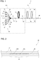
- FIG. 1 illustrates a laser apparatus according to the present embodiment.
- a laser apparatus 1 according to the present embodiment includes a light source LS and a filter device FL.
- the light source LS includes mainly: a pumping light source 20 that emits pumping light; an amplification optical fiber 13 that the pumping light emitted from the pumping light source 20 enters, the amplification optical fiber 13 being doped with an active element that pumps by the pumping light; an optical fiber 12 connected to one end of the amplification optical fiber 13; a high-reflective FBG 31 with which the optical fiber 12 is provided; a combiner 10 that enters the pumping light to the optical fiber 12; an optical fiber 14 connected to the other end of the amplification optical fiber 13; and a low-reflective FBG 32 with which the optical fiber 14 is provided.
- the amplification optical fiber 13, the high-reflective FBG 31, and the low-reflective FBG 32 are constituents of a resonator, and the light source LS according to the present embodiment serves as an apparatus of fiber laser resonator.
- the pumping light source 20 includes a plurality of laser diodes 21 and emits pumping light having a wavelength that pumps the active element doped to the amplification optical fiber 13.
- Each laser diode 21 in the pumping light source 20 is connected to a pumping optical fiber 25.
- Light that the laser diodes 21 each emit propagates in the pumping optical fiber 25 optically connected to the laser diode 21.
- Examples of such a pumping optical fiber 25 include a multimode fiber. In this case, the pumping light propagates, as multimode light, in the pumping optical fiber 25.
- the wavelength of the pumping light is, for example, 915 nm.
- the amplification optical fiber 13 includes a core, an inner cladding surrounding the outer circumferential face of the core without any space, an outer cladding covering the outer circumferential face of the inner cladding, and a sheath covering the outer circumferential face of the outer cladding.
- Examples of the material of the core of the amplification optical fiber 13 include quartz doped with an element, such as germanium, that causes a rise in refractive index, and an active element, such as ytterbium (Yb), that pumps by the light emitted from the pumping light source 20.
- Examples of such an active element include a rare-earth element, the rare-earth element include thulium (Tm), cerium (Ce), neodymium (Nd), europium (Eu), and erbium (Er), in addition to ytterbium described above.
- Examples of the active element further include bismuth (Bi), in addition to the rare-earth element.
- Examples of the material of the inner cladding of the amplification optical fiber 13 include pure quartz doped with no dopant and quartz doped with an element, such as fluorine, that causes a drop in refractive index.
- Examples of the material of the outer cladding of the amplification optical fiber 13 include a resin lower in refractive index than the inner cladding, and quartz doped with an element, such as fluorine, that causes a drop in refractive index.
- Examples of the material of the sheath of the amplification optical fiber 13 include an ultraviolet curable resin different from the resin included in the outer cladding.
- the amplification optical fiber 13 serves as a multimode fiber which supports 2 to 10 linearly polarized (LP) modes.
- the optical fiber 12 is the same in configuration as the amplification optical fiber 13 except for the core doped with no active element. Therefore, the optical fiber 12 serves as a multimode fiber.
- the core of the optical fiber 12 is provided with the high-reflective FBG 31. That is, the high-reflective FBG 31 is provided closer to the one end of the amplification optical fiber 13.
- the high-reflective FBG 31 has a portion high in refractive index repeating in a certain period along the longitudinal direction of the optical fiber 12. Adjustment of the period causes the high-reflective FBG 31 to reflect light having a particular wavelength in light that the active element having been pumped in the amplification optical fiber 13 radiates.
- the high-reflective FBG 31 reflects, for example, light having a wavelength of 1070 nm, for example, with a reflectivity of 99% or more.
- each pumping optical fiber 25 is connected to the inner cladding of the optical fiber 12. That is, the pumping optical fibers 25 connected to the pumping light source 20 are optically coupled to the inner cladding of the amplification optical fiber 13 through the inner cladding of the optical fiber 12.
- an optical fiber 11 is connected to the optical fiber 12.
- the optical fiber 11 has a core the same in diameter as the core of the optical fiber 12.
- One end of the optical fiber 11 is connected to the optical fiber 12, the core of the optical fiber 11 and the core of the optical fiber 12 are optically coupled together.
- a thermal converter E is connected on the opposite side to the combiner 10 side of the optical fiber 11.
- the other end of the amplification optical fiber 13 is connected to the optical fiber 14, the core of the amplification optical fiber 13 and the core of the optical fiber 14 are optically coupled together.
- the optical fiber 14 includes a core similar to the core of the amplification optical fiber 13 except for being doped with no active element, a cladding that surrounds the outer circumferential face of the core without any space and is similar in configuration to the inner cladding of the amplification optical fiber 13, and a sheath covering the outer circumferential face of the cladding. Therefore, the optical fiber 14 serves as a multimode fiber.
- the core of the optical fiber 14 is provided with the low-reflective FBG 32. That is, the low-reflective FBG 32 is provided closer to the other end of the amplification optical fiber 13.
- the low-reflective FBG 32 has a portion high in refractive index repeating in a certain period along the longitudinal direction of the optical fiber 14, and reflects light having a wavelength as at least part of the light that the high-reflective FBG 31 reflects, with a reflectivity lower than that of the high-reflective FBG 31.
- the low-reflective FBG 32 reflects light having a wavelength identical to the wavelength of the light that the high-reflective FBG 31 reflects, with a reflectivity of 50%.
- the high-reflective FBG 31 reflects light having a wavelength of 1070 nm as above, part of the light having the wavelength is transmitted through the low-reflective FBG 32, and then the transmitted light is emitted from the optical fiber 14.
- the light is multimode light, and the wavelength of the light is equivalent to the wavelength of light that resonates due to the resonator including the amplification optical fiber 13, the high-reflective FBG 31, and the low-reflective FBG 32.
- the light is referred to as signal light.
- An optical fiber 40 is connected on the opposite side to the amplification optical fiber 13 side of the optical fiber 14.
- the optical fiber 40 serves as a delivery fiber that propagates the signal light emitted from the light source LS. That is, in the present embodiment, the light source LS includes up to a portion including at least the low-reflective FBG 32 in the optical fiber 14.
- the filter device FL includes mainly the optical fiber 40, a first higher-order mode filter 41, a FBG 45, and a second higher-order mode filter 42.
- the optical fiber 40 connected to the light source LS is similar in configuration to the optical fiber 14. Therefore, the optical fiber 40 serves as a multimode fiber and includes a core similar to the core of the amplification optical fiber 13 except for being doped with no active element, a cladding that surrounds the outer circumferential face of the core without any space and is similar in configuration to the inner cladding of the amplification optical fiber 13, and a sheath covering the outer circumferential face of the cladding. Note that, due to extension of the optical fiber 14, part of the optical fiber 14 may serve as the optical fiber 40.
- the first higher-order mode filter 41 is provided on the light source LS side of the optical fiber 40.
- the first higher-order mode filter 41 removes at least part of the light in any higher order mode than a predetermined mode in the signal light in multimode that propagates in the optical fiber 40.
- the first higher-order mode filter 41 removes the light in any higher order mode than LP 11 mode in the signal light in multimode that propagates in the optical fiber 40.
- the light in LP 01 mode and the light in LP 11 mode propagate in the optical fiber 40, and the light in LP 21 mode, the light in LP 02 mode, and the light in any other higher-order modes are inhibited from propagating.
- the first higher-order mode filter 41 removes the light in any higher order mode than LP 01 mode in the signal light in multimode that propagates in the optical fiber 40.
- the light in LP 01 mode propagates in the optical fiber 40, and the light in LP 11 mode and the light in any other higher-order modes are inhibited from propagating.
- a higher-order mode of light that the first higher-order mode filter removes is not limited to the above examples.
- the first higher-order mode filter 41 is a section bent with a predetermined diameter in the optical fiber 40.
- the wavelength of signal light that the light source LS emits is 1070 nm as above, for example, if the diameter of the core of the optical fiber 40 is 28 ⁇ m, the relative refractive index difference of the core to the cladding is 0.12%, and the light in any higher order mode than LP 11 mode is to be removed from the signal light in multimode that propagates in the core, the first higher-order mode filter 41 is a section bent with a diameter of 100 mm in the optical fiber 40.
- the first higher-order mode filter 41 is a section bent with a diameter of 80 mm in the optical fiber 40.
- the FBG 45 is provided on the opposite side to the light source LS side of the first higher-order mode filter 41 in the optical fiber 40.
- FIG. 2 is a schematic view of the FBG 45.
- the FBG 45 has a high-refractive-index portion 45H higher in refractive index than a core 46 surrounded by a cladding 47 of the optical fiber 40 and a low-refractive-index portion 45L equivalent in refractive index to the core 46 that repeat alternately. Note that, in FIG. 2 , for simplification of the figure, the high-refractive-index portions 45H and the low-refractive-index portions 45L are indicated less in number than those in the actual FBG.
- the FBG 45 in the present example has the interface between each high-refractive-index portion 45H and each low-refractive-index portion 45L, orthogonally to the longitudinal direction of the core 46.
- the FBG 45 transmits the light having a predetermined wavelength propagating in the optical fiber 40 after emitted from the light source LS therethrough and reflects, to the light source LS, the light having a particular wavelength longer than the predetermined wavelength.
- the signal light emitted from the light source LS corresponds to the light having the predetermined wavelength
- Stokes light due to stimulated Raman scattering of the signal light corresponds to the light having the particular wavelength.
- the FBG 45 transmits the signal light therethrough and reflects the Stokes light generating from the signal light, in the exact opposite direction to the propagation direction of the Stokes light incident on the FBG 45. Therefore, the FBG 45 reflects the Stokes light to the light source LS.
- each high-refractive-index portion 45H and each low-refractive-index portion 45L is perpendicular to the longitudinal direction of the core.
- the pitch of the FBG 45 is defined as ⁇
- the wavelength of light that the FBG 45 reflects is defined as ⁇ 1
- a second higher-order mode filter 42 is provided on the opposite side to the first higher-order mode filter 41 side of the FBG 45 in the optical fiber 40. Therefore, the FBG 45 according to the present embodiment is interposed between a pair of higher-order mode filters.
- the second higher-order mode filter 42 is similar in configuration to the first higher-order mode filter 41.
- the leading end of the optical fiber 40 is connected with a glass rod 48 thicker in diameter than the core 46. Therefore, light emitted from the core 46 is widened in diameter by the glass rod 48 for emission.
- pumping light is emitted from each laser diode 21 in the pumping light source 20.
- the pumping light emitted from the pumping light source 20 enters from the pumping optical fibers 25 to the inner cladding of the amplification optical fiber 13 through the inner cladding of the optical fiber 12.
- the pumping light incident on the inner cladding of the amplification optical fiber 13 propagates mainly in the inner cladding and pumps, at the time of passing through the core of the amplification optical fiber 13, the active element with which the core is doped.
- the active element having been pumped radiates spontaneous emission light, at the time of returning to the ground state.
- the spontaneous emission light propagates in the core of the amplification optical fiber 13, then, the light having a part of wavelength is reflected by the high-reflective FBG 31 and the light having the wavelength that the low-reflective FBG 32 reflects in the reflected light is reflected by the low-reflective FBG 32, so that the light oscillates between the high-reflective FBG 31 and the low-reflective FBG 32, namely, in the resonator.
- the light is amplified due to stimulated emission at the time of propagation in the core of the amplification optical fiber 13, resulting in being in laser oscillation. Then, part of the amplified light is transmitted through the low-reflective FBG 32 and then is emitted from the optical fiber 14.
- the optical fiber 14 serves as a multimode fiber and thus signal light in multimode is emitted from the light source LS.
- the signal light emitted from the light source LS enters the optical fiber 40.
- the optical fiber 40 serves as a multimode fiber
- the signal light propagates, in multimode, in the optical fiber 40.
- the signal light propagates in the first higher-order mode filter 41, the light in any higher order mode than the predetermined mode leaks from the core 46, resulting in removal.
- the first higher-order mode filter 41 removes the light in any higher order mode than LP 11 mode in the signal light in multimode that propagates in the optical fiber 40
- the light in LP 01 mode and the light in LP 11 mode propagate from the first higher-order mode filter 41 to the FBG 45 in the optical fiber 40
- the light in LP 21 mode, the light in LP 02 mode, and the light in any other higher-order modes are inhibited from propagating.
- the first higher-order mode filter 41 removes the light in any higher order mode than LP 01 mode in the signal light in multimode that propagates in the optical fiber 40
- the light in LP 01 mode propagates from the first higher-order mode filter 41 to the FBG 45 in the optical fiber 40, and the light in LP 11 mode and the light in any other higher-order modes are inhibited from propagating.
- the signal light When the signal light enters the FBG 45, the signal light is transmitted through the FBG 45.
- the signal light transmitted through the FBG 45 propagates in the second higher-order mode filter 42.
- the light in any higher order mode than the predetermined mode in the signal light has been removed by the first higher-order mode filter 41. Therefore, the second higher-order mode filter 42 removes the light in any higher order mode than the predetermined mode that the first higher-order mode filter 41 was not able to remove or the light in any higher order mode than the predetermined mode excited after transmission through the first higher-order mode filter 41. Therefore, the signal light transmitted through the second higher-order mode filter 42 has a further improvement in beam quality.
- the light transmitted through the second higher-order mode filter 42 enters the glass rod 48, so that the light having the diameter widened is emitted as emitted light.
- a workpiece or the like is irradiated with the emitted light.
- part of the emitted light with which a workpiece or the like is irradiated is reflected from the workpiece and then enters the glass rod 48, so that part of the light having entered enters the core 46 of the optical fiber 40.
- the light propagates as returning light in the optical fiber 40 in the direction to the light source LS, namely, in the backward direction.
- the signal light emitted from the light source LS propagates in the optical fiber 40 in the direction to the glass rod 48, namely, in the forward direction.
- the energy density of the light in the core 46 of the optical fiber 40 Due to such a rise in the energy density of the light in the core 46 of the optical fiber 40 as above, part of the light that propagates from the light source LS or part of the returning light is likely to cause stimulated Raman scattering, resulting in transition to Stokes light.
- the Stokes light can propagate in the forward direction and in the backward direction. Note that, in a case where the signal light is large in power, Stokes light can generate even with no returning light that propagates in the backward direction.
- the FBG 45 reflects the Stokes light in the exact opposite direction to the propagation direction of the Stokes light incident on the FBG 45. Therefore, in a case where the Stokes light generating between the light source LS and the FBG 45 enters the FBG 45, the Stokes light reflected by the FBG 45 propagates in the core 46 to the light source LS. In a case where the Stokes light generating between the FBG 45 and the glass rod 48 enters the FBG 45, the Stokes light reflected by the FBG 45 propagates in the core 46 to the glass rod 48.
- the FBG 45 that reflects the Stokes light as above reflects part of the signal light shorter in wavelength than the Stokes light, obliquely to the longitudinal direction of the core 46.
- the FBG 45 reflects part of the returning light obliquely to the longitudinal direction of the core 46.
- V 2 ⁇ a ⁇ n 1 2 ⁇ n 0 2
- the mode of light capable of propagating in the core includes six modes that are, in order from the lowest mode order, LP 01 mode, LP 11 mode, LP 21 mode, LP 02 mode, LP 31 mode, and LP 12 mode.
- LP 01 mode is 98%
- LP 11 mode is 95%
- LP 21 mode is 90%
- LP 02 mode is 88%
- LP 31 mode is 83%
- LP 12 mode is 67%.
- a higher-order mode of light in the signal light reflected obliquely to the longitudinal direction of the core 46 by the FBG 45 tends to propagate in the cladding, resulting in being easy cladding-mode light.
- the light in any higher order mode than the predetermined mode is removed by the first higher-order mode filter 41.
- the signal light reflected obliquely to the longitudinal direction of the core 46 by the FBG 45 is inhibited from being cladding-mode light.
- the light in any higher order mode than the predetermined mode is removed.
- the returning light with the removal transmitted through the second higher-order mode filter 42 is transmitted through the FBG 45.
- part of the returning light is reflected obliquely to the longitudinal direction of the core 46 by the FBG 45.
- the light in any higher order mode than the predetermined mode is removed from the returning light by the second higher-order mode filter 42.
- the signal light reflected obliquely to the longitudinal direction of the core 46 by the FBG 45 is inhibited from being cladding-mode light.
- the signal light propagates to the FBG 45 through the first higher-order mode filter 41, resulting in inhibition of the power of a higher-order mode of light in the signal light incident on the FBG 45.
- the filter device FL according to the present embodiment enables, even in a case where the light reflected by the FBG 45 becomes cladding-mode light, inhibition of the power thereof, thus, local heat generation can be inhibited.
- the first higher-order mode filter 41 and the second higher-order mode filter 42 according to the present embodiment are each a section bent with the predetermined diameter in the optical fiber 40. Therefore, the first higher-order mode filter 41 and the second higher-order mode filter 42 can be each achieved with a simple configuration.
- the FBG 45 is interposed between a pair of higher-order mode filters that are the first higher-order mode filter 41 and the second higher-order mode filter 42. Therefore, the power of the light in any higher order mode than the predetermined mode in the signal light that propagates to the FBG 45 and the power of the light in any higher order mode than the predetermined mode in the returning light that propagates to the FBG 45 can be inhibited. Therefore, the power of cladding-mode light due to reflection of part of the signal light and part of the returning light incident on the FBG 45 by the FBG 45 can be inhibited, thus, local heat generation can be inhibited.
- the laser apparatus 1 including the filter device FL as above can inhibit local heat generation.
- the FBG 45 has the interface between each high-refractive-index portion 45H and each low-refractive-index portion 45L, orthogonally to the longitudinal direction of the core 46.
- the FBG 45 according to the present embodiment is not limited to this.
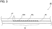
- FIG. 3 is a schematic view of another exemplary FBG 45. Note that, for description with FIG. 3 , unless otherwise noted, constituents the same as or similar to those according to the embodiment are denoted with the same reference signs, and the duplicate description thereof will be omitted.
- the FBG 45 may be a slanted FBG.
- the slanted FBG has the interface between each high-refractive-index portion 45H and each low-refractive-index portion 45L, at a specific angle, different from a right angle, to the longitudinal direction of the core 46.
- the interface is provided at an angle of 2.5 degrees to the longitudinal direction of the core 46.
- the first higher-order mode filter 41 removes the light in any higher order mode than the predetermined mode in the signal light, so that the signal light reflected obliquely to the longitudinal direction of the core 46 by the FBG 45 is inhibited from being cladding-mode light.
- the second higher-order mode filter 42 removes the light in any higher order mode than the predetermined mode in the returning light, so that the signal light reflected obliquely to the longitudinal direction of the core 46 by the FBG 45 is inhibited from being cladding-mode light.
- the light source LS that serves as an apparatus of fiber laser resonator has been exemplarily given.
- the present invention is not limited to this, and thus the light source LS is required at least to enter light having the predetermined wavelength to the optical fiber 40.
- the light source LS may be a master oscillator power amplifier (MO-PA) fiber laser apparatus.
- the light source LS may be a solid-state laser apparatus, such as a semiconductor laser apparatus, or may be a gas laser apparatus.
- the filter device FL includes the second higher-order mode filter 42, but does not necessarily include the second higher-order mode filter 42. Even in a case where the second higher-order mode filter 42 is provided, the second higher-order mode filter 42 is not necessarily similar in configuration to the first higher-order mode filter 41.
- the first higher-order mode filter 41 may remove the light in any higher order mode than LP 11 mode and the second higher-order mode filter 42 may remove the light in any higher order mode than LP 01 mode.
- the first higher-order mode filter 41 and the second higher-order mode filter 42 are each required at least to remove at least part of the light in any higher order mode than the predetermined mode in the light in multimode that propagates in the optical fiber 40. Therefore, the first higher-order mode filter 41 and the second higher-order mode filter 42 are each not necessarily a section bent with the predetermined diameter in the optical fiber 40, and thus may each have a form different from that according to the embodiment.
- the filter device and the laser apparatus that enable inhibition of local heat generation and are utilizable in various industries, such as a laser processing field and a medical field.
Landscapes
- Physics & Mathematics (AREA)
- Electromagnetism (AREA)
- Optics & Photonics (AREA)
- Engineering & Computer Science (AREA)
- Plasma & Fusion (AREA)
- General Physics & Mathematics (AREA)
- Lasers (AREA)
- Light Guides In General And Applications Therefor (AREA)
- Optical Fibers, Optical Fiber Cores, And Optical Fiber Bundles (AREA)
Abstract
Description
- The present invention relates to a filter device and a laser apparatus that enable inhibition of local heat generation.
- A fiber laser apparatus is used in various fields, such as a laser processing field and a medical field since the fiber laser apparatus enables high optical power density in a small beam spot due to its excellent light condensing property.
- In recent years, the power of light emitted from fiber laser systems has increased, an increase in the power density of light that propagates in an optical fiber is likely to cause Stokes light due to stimulated Raman scattering (SRS). Generating of such Stokes light causes easy transition of energy from proper light that the fiber laser apparatus emits to the Stokes light, thus, the power of the Stokes light tends to increase even in an optical fiber having no function of amplifying light. Therefore, in a case where Stokes light is generated, preferably, the Stokes light is removed while the Stokes light is small in power.
-
Patent Literature 1 discloses a fiber laser apparatus provided with a plurality of slanted fiber Bragg gratings (FBGs). In the fiber laser apparatus, each FBG reflects Stokes light outward from the core. - [Patent Literature 1]
US Patent Application Publication No. 2016/0111851 - A FBG has a plurality of high-refractive-index portions higher in refractive index than the core out of a portion provided with the FBG and a plurality of low-refractive-index portions equivalent in refractive index to the core, each high-refractive-index portion and each low-refractive-index portion alternating with each other. In a typical FBG, the interface between each high-refractive-index portion and each low-refractive-index portion is provided orthogonally to the longitudinal direction of the core. In this case, when the effective refractive index of the core is defined as neff, the period of the FBG along the longitudinal direction of the core is defined as A, and the wavelength of light that propagates in the core is defined as λ, at least part of the light having the wavelength λ = 2neffΛ incident on the FBG is reflected in the exact opposite direction to the incident direction to the FBG. In some cases, depending on the refractive index of the high-refractive-index portions or the number of the high-refractive-index portions, almost all the light having the wavelength λ = 2neffΛ can be reflected in the exact opposite direction to the incident direction to the FBG. Part of the light having the wavelength λ < 2neffΛ incident on the FBG is reflected at a specific angle relative to the exact opposite direction to the incident direction to the FBG. A larger difference between λ and 2neffΛ increases the angle.
- For example, a fiber laser apparatus is provided with a FBG that reflects Stokes light due to stimulated Raman scattering occurring from signal light in response to transmission of the signal light, in the exact opposite direction to the incident direction to the FBG, to inhibit the Stokes light from propagating to the downstream side of the FBG in the propagation direction of the signal light. In this case, because the wavelength of the signal light is shorter than the wavelength of the Stokes light, it is found that part of the signal light is reflected at a specific angle relative to the exact opposite direction to the incident direction to the FBG. As above, a phenomenon in which part of signal light is reflected at a specific angle relative to the exact opposite direction to the incident direction to a FBG, occurs in a slanted FBG that reflects Stokes light at a specific angle relative to the longitudinal direction of an optical fiber. In a case where such signal light reflected at a specific angle exceeds the numerical aperture (NA) of the core, the reflected signal light propagates in the cladding, resulting in being cladding-mode light. Typically, the cladding of an optical fiber is covered with a sheath made of resin. Thus, cladding-mode light is absorbed into the sheath of the cladding, resulting in being heat. In a case where the power of signal light is large such as in a high-power fiber laser apparatus, the sheath is likely to be damaged even though the ratio of the signal light as cladding-mode light reflected by a FBG as above is small, because the energy thereof is large.
- Therefore, an object of the present invention is to provide a filter device and a laser apparatus that enable inhibition of local heat generation.
- In order to achieve the object, a filter device according to the present invention includes: an optical fiber that allows light having a predetermined wavelength to propagate in multimode; a higher-order mode filter that removes at least part of the light in any higher order mode than a predetermined mode in the light in the multimode propagating in the optical fiber; and a fiber Bragg grating (FBG) that transmits the light having the predetermined wavelength and reflects light having a particular wavelength longer than the predetermined wavelength.
- As above, the filter device transmits the light having the predetermined wavelength therethrough and inhibits transmission of the light having the particular wavelength longer in wavelength than the light having the predetermined wavelength, thus, the light having the particular wavelength can be inhibited from being propagated through the filter device. Even such a FBG that reflects light having a particular wavelength longer than a predetermined wavelength as above now reflects part of light having the predetermined wavelength shorter than the particular wavelength, at a specific angle relative to the exact opposite direction to the incident direction to the FBG. As the mode of light gets higher in order, the optical confinement ability of a core is low. Therefore, a higher-order mode of light in such light reflected at a specific angle as above tends to be cladding-mode light. Thus, in the filter device, the light having the predetermined wavelength propagates to the FBG through the higher-order mode filter. Thus, before the light having the predetermined wavelength enters the FBG, at least part of the light in any higher order mode than the predetermined mode in the light having the predetermined wavelength can be removed in advance by the higher-order mode filter. Thus, the power of a higher-order mode of light is inhibited in the light incident on the FBG. Therefore, the power of a higher-order mode of light that tends to be cladding-mode light is inhibited in the light having the predetermined wavelength reflected at a specific angle relative to the exact opposite direction to the incident direction to the FBG.
- Therefore, the filter device according to the present invention enables, even in a case where the light reflected by the FBG becomes cladding-mode light, inhibition of the power thereof, thus, local heat generation can be inhibited.
- The FBG may be of a slanted type.
- In this case, the light having the particular wavelength reflected by the FBG can be emitted in a particular direction in accordance with the slant angle of the FBG. Therefore, unnecessary light can be inhibited from returning to the core.
- Preferably, the higher-order mode filter is a section bent with a predetermined diameter in the optical fiber.
- In this case, the higher-order mode filter can be achieved with a simple configuration.
- The higher-order mode filter may remove the light in any higher order mode than LP11 mode.
- Such a configuration enables inhibition of the power of the light in LP02 mode, the light in LP21 mode, and the light in any other higher-order modes, so that an improvement can be made in beam quality.
- In this case, the higher-order mode filter may remove the light in any higher order mode than LP01 mode.
- Such a configuration enables inhibition of the power of the light in LP11 mode and the light in any other higher-order modes, so that a further improvement can be made in beam quality.
- Preferably, the light having the particular wavelength is Stokes light of the light having the predetermined wavelength.
- In this case, at the time of propagation of the light having the predetermined wavelength and having a large power in the optical fiber, the Stokes light generating from the light having the predetermined wavelength can be inhibited from propagating through the filter device. Therefore, for example, in a case where a laser apparatus has signal light large in power and the signal light causes Stokes light, the filter device is useful.
- Preferably, the filter device is provided with a pair of the higher-order mode filters, and the FBG is interposed between the pair of the higher-order mode filters.
- In this case, the power of the light in any higher order mode than the predetermined mode in the light having the predetermined wavelength propagating from one side of the FBG to the FBG and the power of the light in any higher order mode than the predetermined mode in the light having the predetermined wavelength propagating from the other side of the FBG to the FBG can be inhibited. Therefore, even in a case where the light having the predetermined wavelength propagates either from the one side or other side of the FBG to the FBG, the power of cladding-mode light due to reflection of part of the light having the predetermined wavelength by the FBG can be inhibited, thus, local heat generation can be inhibited.
- In order to achieve the object, a laser apparatus according to the present invention includes: the filter device described above; and a light source that emits the light having the predetermined wavelength, in which the optical fiber propagates the light emitted from the light source, and the FBG transmits the light having the predetermined wavelength transmitted through the higher-order mode filter after emitted from the light source, and reflects the light having the particular wavelength.
- In the laser apparatus as above, although the light having the predetermined wavelength emitted from the light source propagates in multimode in the optical fiber, the power of the light in any higher order mode than the predetermined mode is inhibited by the higher-order mode filter. Thus, the light with inhibition of the power of the light in any higher order mode than the predetermined mode is transmitted through the FBG. At this time, part of the light having the predetermined wavelength is likely to be reflected at a specific angle relative to the exact opposite direction to the incident direction to the FBG. However, the power of a higher-order mode of light that tends to be cladding-mode light, in the reflected light, is inhibited. Therefore, the laser apparatus according to the present invention enables inhibition of local heat generation.
- As described above, the present invention provides the filter device and the laser apparatus that enable inhibition of local heat generation.
-
-
FIG. 1 illustrates a laser apparatus according to an embodiment of the present invention. -
FIG. 2 is a schematic view of a fiber Bragg grating (FBG). -
FIG. 3 is a schematic view of another exemplary FBG. - A filter device and a laser apparatus according to a preferred embodiment of the present invention will be described in detail below with reference to the drawings. The embodiment to be exemplified below is intended for easy understanding of the present invention. Thus, the present invention is not limited to the embodiment. Alternations and improvements may be made without departing from the spirit of the present invention. Note that, for easy understanding, the dimensions of each member in the drawings for reference below are changed, in some cases.
-
FIG. 1 illustrates a laser apparatus according to the present embodiment. As illustrated inFIG. 1 , alaser apparatus 1 according to the present embodiment includes a light source LS and a filter device FL. - The light source LS includes mainly: a pumping
light source 20 that emits pumping light; an amplificationoptical fiber 13 that the pumping light emitted from the pumpinglight source 20 enters, the amplificationoptical fiber 13 being doped with an active element that pumps by the pumping light; anoptical fiber 12 connected to one end of the amplificationoptical fiber 13; a high-reflective FBG 31 with which theoptical fiber 12 is provided; acombiner 10 that enters the pumping light to theoptical fiber 12; anoptical fiber 14 connected to the other end of the amplificationoptical fiber 13; and a low-reflective FBG 32 with which theoptical fiber 14 is provided. The amplificationoptical fiber 13, the high-reflective FBG 31, and the low-reflective FBG 32 are constituents of a resonator, and the light source LS according to the present embodiment serves as an apparatus of fiber laser resonator. - The pumping
light source 20 includes a plurality oflaser diodes 21 and emits pumping light having a wavelength that pumps the active element doped to the amplificationoptical fiber 13. Eachlaser diode 21 in the pumpinglight source 20 is connected to a pumpingoptical fiber 25. Light that thelaser diodes 21 each emit propagates in the pumpingoptical fiber 25 optically connected to thelaser diode 21. Examples of such a pumpingoptical fiber 25 include a multimode fiber. In this case, the pumping light propagates, as multimode light, in the pumpingoptical fiber 25. Note that, in a case where the active element doped to the amplificationoptical fiber 13 is ytterbium as described below, the wavelength of the pumping light is, for example, 915 nm. - The amplification
optical fiber 13 includes a core, an inner cladding surrounding the outer circumferential face of the core without any space, an outer cladding covering the outer circumferential face of the inner cladding, and a sheath covering the outer circumferential face of the outer cladding. Examples of the material of the core of the amplificationoptical fiber 13 include quartz doped with an element, such as germanium, that causes a rise in refractive index, and an active element, such as ytterbium (Yb), that pumps by the light emitted from the pumpinglight source 20. Examples of such an active element include a rare-earth element, the rare-earth element include thulium (Tm), cerium (Ce), neodymium (Nd), europium (Eu), and erbium (Er), in addition to ytterbium described above. Examples of the active element further include bismuth (Bi), in addition to the rare-earth element. Examples of the material of the inner cladding of the amplificationoptical fiber 13 include pure quartz doped with no dopant and quartz doped with an element, such as fluorine, that causes a drop in refractive index. Examples of the material of the outer cladding of the amplificationoptical fiber 13 include a resin lower in refractive index than the inner cladding, and quartz doped with an element, such as fluorine, that causes a drop in refractive index. Examples of the material of the sheath of the amplificationoptical fiber 13 include an ultraviolet curable resin different from the resin included in the outer cladding. - In the present embodiment, the amplification
optical fiber 13 serves as a multimode fiber which supports 2 to 10 linearly polarized (LP) modes. - One end of the amplification
optical fiber 13 is connected to theoptical fiber 12, the core of the amplificationoptical fiber 13 and the core of theoptical fiber 12 are optically coupled together, and the inner cladding of the amplificationoptical fiber 13 and the inner cladding of theoptical fiber 12 are optically coupled together. Theoptical fiber 12 is the same in configuration as the amplificationoptical fiber 13 except for the core doped with no active element. Therefore, theoptical fiber 12 serves as a multimode fiber. - The core of the
optical fiber 12 is provided with the high-reflective FBG 31. That is, the high-reflective FBG 31 is provided closer to the one end of the amplificationoptical fiber 13. The high-reflective FBG 31 has a portion high in refractive index repeating in a certain period along the longitudinal direction of theoptical fiber 12. Adjustment of the period causes the high-reflective FBG 31 to reflect light having a particular wavelength in light that the active element having been pumped in the amplificationoptical fiber 13 radiates. In a case where the active element doped to the amplificationoptical fiber 13 is doped is ytterbium as described above, the high-reflective FBG 31 reflects, for example, light having a wavelength of 1070 nm, for example, with a reflectivity of 99% or more. - In the
combiner 10, the core of each pumpingoptical fiber 25 is connected to the inner cladding of theoptical fiber 12. That is, the pumpingoptical fibers 25 connected to the pumpinglight source 20 are optically coupled to the inner cladding of the amplificationoptical fiber 13 through the inner cladding of theoptical fiber 12. - In the
combiner 10, anoptical fiber 11 is connected to theoptical fiber 12. For example, theoptical fiber 11 has a core the same in diameter as the core of theoptical fiber 12. One end of theoptical fiber 11 is connected to theoptical fiber 12, the core of theoptical fiber 11 and the core of theoptical fiber 12 are optically coupled together. A thermal converter E is connected on the opposite side to thecombiner 10 side of theoptical fiber 11. - The other end of the amplification
optical fiber 13 is connected to theoptical fiber 14, the core of the amplificationoptical fiber 13 and the core of theoptical fiber 14 are optically coupled together. Theoptical fiber 14 includes a core similar to the core of the amplificationoptical fiber 13 except for being doped with no active element, a cladding that surrounds the outer circumferential face of the core without any space and is similar in configuration to the inner cladding of the amplificationoptical fiber 13, and a sheath covering the outer circumferential face of the cladding. Therefore, theoptical fiber 14 serves as a multimode fiber. - The core of the
optical fiber 14 is provided with the low-reflective FBG 32. That is, the low-reflective FBG 32 is provided closer to the other end of the amplificationoptical fiber 13. The low-reflective FBG 32 has a portion high in refractive index repeating in a certain period along the longitudinal direction of theoptical fiber 14, and reflects light having a wavelength as at least part of the light that the high-reflective FBG 31 reflects, with a reflectivity lower than that of the high-reflective FBG 31. For example, the low-reflective FBG 32 reflects light having a wavelength identical to the wavelength of the light that the high-reflective FBG 31 reflects, with a reflectivity of 50%. Therefore, in a case where the high-reflective FBG 31 reflects light having a wavelength of 1070 nm as above, part of the light having the wavelength is transmitted through the low-reflective FBG 32, and then the transmitted light is emitted from theoptical fiber 14. The light is multimode light, and the wavelength of the light is equivalent to the wavelength of light that resonates due to the resonator including the amplificationoptical fiber 13, the high-reflective FBG 31, and the low-reflective FBG 32. Hereinafter, in some cases, the light is referred to as signal light. - An
optical fiber 40 is connected on the opposite side to the amplificationoptical fiber 13 side of theoptical fiber 14. Theoptical fiber 40 serves as a delivery fiber that propagates the signal light emitted from the light source LS. That is, in the present embodiment, the light source LS includes up to a portion including at least the low-reflective FBG 32 in theoptical fiber 14. - The filter device FL includes mainly the
optical fiber 40, a first higher-order mode filter 41, aFBG 45, and a second higher-order mode filter 42. Theoptical fiber 40 connected to the light source LS is similar in configuration to theoptical fiber 14. Therefore, theoptical fiber 40 serves as a multimode fiber and includes a core similar to the core of the amplificationoptical fiber 13 except for being doped with no active element, a cladding that surrounds the outer circumferential face of the core without any space and is similar in configuration to the inner cladding of the amplificationoptical fiber 13, and a sheath covering the outer circumferential face of the cladding. Note that, due to extension of theoptical fiber 14, part of theoptical fiber 14 may serve as theoptical fiber 40. - The first higher-
order mode filter 41 is provided on the light source LS side of theoptical fiber 40. The first higher-order mode filter 41 removes at least part of the light in any higher order mode than a predetermined mode in the signal light in multimode that propagates in theoptical fiber 40. For example, the first higher-order mode filter 41 removes the light in any higher order mode than LP11 mode in the signal light in multimode that propagates in theoptical fiber 40. In this case, on the opposite side to the light source LS side of the first higher-order mode filter 41, the light in LP01 mode and the light in LP11 mode propagate in theoptical fiber 40, and the light in LP21 mode, the light in LP02 mode, and the light in any other higher-order modes are inhibited from propagating. Alternatively, for example, the first higher-order mode filter 41 removes the light in any higher order mode than LP01 mode in the signal light in multimode that propagates in theoptical fiber 40. In this case, on the opposite side to the light source LS side of the first higher-order mode filter 41, the light in LP01 mode propagates in theoptical fiber 40, and the light in LP11 mode and the light in any other higher-order modes are inhibited from propagating. Note that a higher-order mode of light that the first higher-order mode filter removes is not limited to the above examples. - In the present embodiment, the first higher-
order mode filter 41 is a section bent with a predetermined diameter in theoptical fiber 40. In a case where the wavelength of signal light that the light source LS emits is 1070 nm as above, for example, if the diameter of the core of theoptical fiber 40 is 28 µm, the relative refractive index difference of the core to the cladding is 0.12%, and the light in any higher order mode than LP11 mode is to be removed from the signal light in multimode that propagates in the core, the first higher-order mode filter 41 is a section bent with a diameter of 100 mm in theoptical fiber 40. In a case where the diameter of the core of theoptical fiber 40 and the relative refractive index difference of the core to the cladding are the same as those in the above example, if the light in any higher order mode than LP01 mode is to be removed from the signal light in multimode that propagates in the core, the first higher-order mode filter 41 is a section bent with a diameter of 80 mm in theoptical fiber 40. - The
FBG 45 is provided on the opposite side to the light source LS side of the first higher-order mode filter 41 in theoptical fiber 40.FIG. 2 is a schematic view of theFBG 45. TheFBG 45 has a high-refractive-index portion 45H higher in refractive index than a core 46 surrounded by acladding 47 of theoptical fiber 40 and a low-refractive-index portion 45L equivalent in refractive index to the core 46 that repeat alternately. Note that, inFIG. 2 , for simplification of the figure, the high-refractive-index portions 45H and the low-refractive-index portions 45L are indicated less in number than those in the actual FBG. TheFBG 45 in the present example has the interface between each high-refractive-index portion 45H and each low-refractive-index portion 45L, orthogonally to the longitudinal direction of thecore 46. TheFBG 45 transmits the light having a predetermined wavelength propagating in theoptical fiber 40 after emitted from the light source LS therethrough and reflects, to the light source LS, the light having a particular wavelength longer than the predetermined wavelength. In the present embodiment, for theFBG 45, the signal light emitted from the light source LS corresponds to the light having the predetermined wavelength, and Stokes light due to stimulated Raman scattering of the signal light corresponds to the light having the particular wavelength. Therefore, theFBG 45 transmits the signal light therethrough and reflects the Stokes light generating from the signal light, in the exact opposite direction to the propagation direction of the Stokes light incident on theFBG 45. Therefore, theFBG 45 reflects the Stokes light to the light source LS. - In the
FBG 45 according to the present embodiment, the interface between each high-refractive-index portion 45H and each low-refractive-index portion 45L is perpendicular to the longitudinal direction of the core. In a case where the effective refractive index of thecore 46 is defined as neff, the pitch of theFBG 45 is defined as Λ, and the wavelength of light that theFBG 45 reflects is defined as λ1, the pitch A has a level such that the following expression is satisfied; λ1 = 2neffΛ. Thus, for example, in a case where the wavelength of signal light that the light source LS emits is defined as λ2 and the wavelength of Stokes light generating from the signal light is defined as λ1, λ2 = 1070 nm as above leads to λ1 = 1125 nm. In this case, for example, neff = 1.450 leads to A = 388 nm. - A second higher-
order mode filter 42 is provided on the opposite side to the first higher-order mode filter 41 side of theFBG 45 in theoptical fiber 40. Therefore, theFBG 45 according to the present embodiment is interposed between a pair of higher-order mode filters. In the present embodiment, the second higher-order mode filter 42 is similar in configuration to the first higher-order mode filter 41. - The leading end of the
optical fiber 40 is connected with aglass rod 48 thicker in diameter than thecore 46. Therefore, light emitted from thecore 46 is widened in diameter by theglass rod 48 for emission. - Next, the operation of the
laser apparatus 1 will be described. - First, pumping light is emitted from each
laser diode 21 in the pumpinglight source 20. The pumping light emitted from the pumpinglight source 20 enters from the pumpingoptical fibers 25 to the inner cladding of the amplificationoptical fiber 13 through the inner cladding of theoptical fiber 12. The pumping light incident on the inner cladding of the amplificationoptical fiber 13 propagates mainly in the inner cladding and pumps, at the time of passing through the core of the amplificationoptical fiber 13, the active element with which the core is doped. The active element having been pumped radiates spontaneous emission light, at the time of returning to the ground state. The spontaneous emission light propagates in the core of the amplificationoptical fiber 13, then, the light having a part of wavelength is reflected by the high-reflective FBG 31 and the light having the wavelength that the low-reflective FBG 32 reflects in the reflected light is reflected by the low-reflective FBG 32, so that the light oscillates between the high-reflective FBG 31 and the low-reflective FBG 32, namely, in the resonator. The light is amplified due to stimulated emission at the time of propagation in the core of the amplificationoptical fiber 13, resulting in being in laser oscillation. Then, part of the amplified light is transmitted through the low-reflective FBG 32 and then is emitted from theoptical fiber 14. As above, theoptical fiber 14 serves as a multimode fiber and thus signal light in multimode is emitted from the light source LS. - The signal light emitted from the light source LS enters the
optical fiber 40. As above, because theoptical fiber 40 serves as a multimode fiber, the signal light propagates, in multimode, in theoptical fiber 40. When the signal light propagates in the first higher-order mode filter 41, the light in any higher order mode than the predetermined mode leaks from thecore 46, resulting in removal. As above, in a case where the first higher-order mode filter 41 removes the light in any higher order mode than LP11 mode in the signal light in multimode that propagates in theoptical fiber 40, the light in LP01 mode and the light in LP11 mode propagate from the first higher-order mode filter 41 to theFBG 45 in theoptical fiber 40, and the light in LP21 mode, the light in LP02 mode, and the light in any other higher-order modes are inhibited from propagating. As above, in a case where the first higher-order mode filter 41 removes the light in any higher order mode than LP01 mode in the signal light in multimode that propagates in theoptical fiber 40, the light in LP01 mode propagates from the first higher-order mode filter 41 to theFBG 45 in theoptical fiber 40, and the light in LP11 mode and the light in any other higher-order modes are inhibited from propagating. - When the signal light enters the
FBG 45, the signal light is transmitted through theFBG 45. The signal light transmitted through theFBG 45 propagates in the second higher-order mode filter 42. The light in any higher order mode than the predetermined mode in the signal light has been removed by the first higher-order mode filter 41. Therefore, the second higher-order mode filter 42 removes the light in any higher order mode than the predetermined mode that the first higher-order mode filter 41 was not able to remove or the light in any higher order mode than the predetermined mode excited after transmission through the first higher-order mode filter 41. Therefore, the signal light transmitted through the second higher-order mode filter 42 has a further improvement in beam quality. - The light transmitted through the second higher-
order mode filter 42 enters theglass rod 48, so that the light having the diameter widened is emitted as emitted light. A workpiece or the like is irradiated with the emitted light. - In some cases, part of the emitted light with which a workpiece or the like is irradiated is reflected from the workpiece and then enters the
glass rod 48, so that part of the light having entered enters thecore 46 of theoptical fiber 40. The light propagates as returning light in theoptical fiber 40 in the direction to the light source LS, namely, in the backward direction. As above, the signal light emitted from the light source LS propagates in theoptical fiber 40 in the direction to theglass rod 48, namely, in the forward direction. Thus, combination of the energy of the light in the forward direction and the energy of the light in the backward direction causes a rise in the energy density of the light in thecore 46 of theoptical fiber 40. Due to such a rise in the energy density of the light in thecore 46 of theoptical fiber 40 as above, part of the light that propagates from the light source LS or part of the returning light is likely to cause stimulated Raman scattering, resulting in transition to Stokes light. The Stokes light can propagate in the forward direction and in the backward direction. Note that, in a case where the signal light is large in power, Stokes light can generate even with no returning light that propagates in the backward direction. - As above, the
FBG 45 reflects the Stokes light in the exact opposite direction to the propagation direction of the Stokes light incident on theFBG 45. Therefore, in a case where the Stokes light generating between the light source LS and theFBG 45 enters theFBG 45, the Stokes light reflected by theFBG 45 propagates in the core 46 to the light source LS. In a case where the Stokes light generating between theFBG 45 and theglass rod 48 enters theFBG 45, the Stokes light reflected by theFBG 45 propagates in the core 46 to theglass rod 48. - Even such a FBG that reflects light having a particular wavelength longer than a predetermined wavelength as above reflects part of light having the predetermined wavelength shorter than the particular wavelength, at a specific angle relative to the exact opposite direction to the incident direction to the FBG. Therefore, the
FBG 45 that reflects the Stokes light as above reflects part of the signal light shorter in wavelength than the Stokes light, obliquely to the longitudinal direction of thecore 46. In a case where part of the emitted light with which a workpiece or the like is irradiated is reflected from the workpiece and then propagates as returning light in theoptical fiber 40 to the light source LS, because the returning light is the same in wavelength as the signal light, theFBG 45 reflects part of the returning light obliquely to the longitudinal direction of thecore 46. - As the mode of light gets higher in order, the optical confinement ability of a core is low. Now, assumed is a step-index optical fiber having a V number of 6.0. The V number is called the normalized frequency and is given by the following expression. Note that, in the following expression, a represents the radius of the core of an optical fiber, λ represents the wavelength of light that propagates in the optical fiber, n1 represents the refractive index of the core of the optical fiber, and n0 represents the refractive index of the cladding of the optical fiber.

- For a step-index optical fiber having a V number of 6.0, the mode of light capable of propagating in the core includes six modes that are, in order from the lowest mode order, LP01 mode, LP11 mode, LP21 mode, LP02 mode, LP31 mode, and LP12 mode. For the confinement rate of light of the respective modes to the core, LP01 mode is 98%, LP11 mode is 95%, LP21 mode is 90%, LP02 mode is 88%, LP31 mode is 83%, and LP12 mode is 67%. Thus, a higher-order mode of light reduces the confinement ability of the core, resulting in easy leakage from the core.
- Therefore, a higher-order mode of light in the signal light reflected obliquely to the longitudinal direction of the core 46 by the
FBG 45 tends to propagate in the cladding, resulting in being easy cladding-mode light. However, from the signal light according to the present embodiment, the light in any higher order mode than the predetermined mode is removed by the first higher-order mode filter 41. Thus, in comparison to a case where no light in any higher order mode than the predetermined mode is removed by the first higher-order mode filter 41, the signal light reflected obliquely to the longitudinal direction of the core 46 by theFBG 45 is inhibited from being cladding-mode light. - As above, at the time of transmission of the returning light the same in wavelength as the signal light through the second higher-
order mode filter 42, the light in any higher order mode than the predetermined mode is removed. The returning light with the removal transmitted through the second higher-order mode filter 42 is transmitted through theFBG 45. As above, part of the returning light is reflected obliquely to the longitudinal direction of the core 46 by theFBG 45. However, in the present embodiment, the light in any higher order mode than the predetermined mode is removed from the returning light by the second higher-order mode filter 42. Thus, in comparison to a case where no light in any higher order mode than the predetermined mode is removed by the second higher-order mode filter 42, the signal light reflected obliquely to the longitudinal direction of the core 46 by theFBG 45 is inhibited from being cladding-mode light. - As described above, according to the present embodiment, the signal light propagates to the
FBG 45 through the first higher-order mode filter 41, resulting in inhibition of the power of a higher-order mode of light in the signal light incident on theFBG 45. Thus, even in the component of the signal light reflected at a specific angle relative to the exact opposite direction to the propagation direction of the signal light incident on theFBG 45, inhibited is the power of a higher-order mode of light that tends to be cladding-mode light. Therefore, the filter device FL according to the present embodiment enables, even in a case where the light reflected by theFBG 45 becomes cladding-mode light, inhibition of the power thereof, thus, local heat generation can be inhibited. - The first higher-
order mode filter 41 and the second higher-order mode filter 42 according to the present embodiment are each a section bent with the predetermined diameter in theoptical fiber 40. Therefore, the first higher-order mode filter 41 and the second higher-order mode filter 42 can be each achieved with a simple configuration. - In the present embodiment, the
FBG 45 is interposed between a pair of higher-order mode filters that are the first higher-order mode filter 41 and the second higher-order mode filter 42. Therefore, the power of the light in any higher order mode than the predetermined mode in the signal light that propagates to theFBG 45 and the power of the light in any higher order mode than the predetermined mode in the returning light that propagates to theFBG 45 can be inhibited. Therefore, the power of cladding-mode light due to reflection of part of the signal light and part of the returning light incident on theFBG 45 by theFBG 45 can be inhibited, thus, local heat generation can be inhibited. - Therefore, the
laser apparatus 1 including the filter device FL as above can inhibit local heat generation. - The embodiment of the present invention has been described above. However, the present invention is not limited to this, and thus appropriate alternations may be made.
- In the description of the embodiment, for example, the
FBG 45 has the interface between each high-refractive-index portion 45H and each low-refractive-index portion 45L, orthogonally to the longitudinal direction of thecore 46. However, theFBG 45 according to the present embodiment is not limited to this.FIG. 3 is a schematic view of anotherexemplary FBG 45. Note that, for description withFIG. 3 , unless otherwise noted, constituents the same as or similar to those according to the embodiment are denoted with the same reference signs, and the duplicate description thereof will be omitted. As illustrated inFIG. 3 , theFBG 45 may be a slanted FBG. The slanted FBG has the interface between each high-refractive-index portion 45H and each low-refractive-index portion 45L, at a specific angle, different from a right angle, to the longitudinal direction of thecore 46. For example, the interface is provided at an angle of 2.5 degrees to the longitudinal direction of thecore 46. Even with such a slanted FBG, part of signal light incident on theFBG 45 is reflected at a specific angle relative to the exact opposite direction to the incident direction to theFBG 45. Therefore, as described above, the first higher-order mode filter 41 removes the light in any higher order mode than the predetermined mode in the signal light, so that the signal light reflected obliquely to the longitudinal direction of the core 46 by theFBG 45 is inhibited from being cladding-mode light. As described above, the second higher-order mode filter 42 removes the light in any higher order mode than the predetermined mode in the returning light, so that the signal light reflected obliquely to the longitudinal direction of the core 46 by theFBG 45 is inhibited from being cladding-mode light. - In the embodiment, the light source LS that serves as an apparatus of fiber laser resonator has been exemplarily given. However, the present invention is not limited to this, and thus the light source LS is required at least to enter light having the predetermined wavelength to the
optical fiber 40. For example, the light source LS may be a master oscillator power amplifier (MO-PA) fiber laser apparatus. The light source LS may be a solid-state laser apparatus, such as a semiconductor laser apparatus, or may be a gas laser apparatus. - The filter device FL according to the embodiment includes the second higher-
order mode filter 42, but does not necessarily include the second higher-order mode filter 42. Even in a case where the second higher-order mode filter 42 is provided, the second higher-order mode filter 42 is not necessarily similar in configuration to the first higher-order mode filter 41. For example, the first higher-order mode filter 41 may remove the light in any higher order mode than LP11 mode and the second higher-order mode filter 42 may remove the light in any higher order mode than LP01 mode. - The first higher-
order mode filter 41 and the second higher-order mode filter 42 are each required at least to remove at least part of the light in any higher order mode than the predetermined mode in the light in multimode that propagates in theoptical fiber 40. Therefore, the first higher-order mode filter 41 and the second higher-order mode filter 42 are each not necessarily a section bent with the predetermined diameter in theoptical fiber 40, and thus may each have a form different from that according to the embodiment. - According to the present invention, provided are the filter device and the laser apparatus that enable inhibition of local heat generation and are utilizable in various industries, such as a laser processing field and a medical field.
Claims (8)
- A filter device comprising:an optical fiber that allows light having a predetermined wavelength to propagate in multimode;a higher-order mode filter that removes at least part of the light in any higher order mode than a predetermined mode in the light in the multimode propagating in the optical fiber; anda fiber Bragg grating that transmits the light having the predetermined wavelength and reflects light having a particular wavelength longer than the predetermined wavelength.
- The filter device according to claim 1, wherein
the fiber Bragg grating is of a slanted type. - The filter device according to claim 1 or 2, wherein
the higher-order mode filter is a section bent with a predetermined diameter in the optical fiber. - The filter device according to any one of claims 1 to 3, wherein
the higher-order mode filter removes the light in any higher order mode than LP11 mode. - The filter device according to claim 4, wherein
the higher-order mode filter removes the light in any higher order mode than LP01 mode. - The filter device according to any one of claims 1 to 5, wherein
the light having the particular wavelength is Stokes light of the light having the predetermined wavelength. - The filter device according to any one of claims 1 to 6, whereina pair of the higher-order mode filters is provided, andthe fiber Bragg grating is interposed between the pair of the higher-order mode filters.
- A laser apparatus comprising:the filter device according to any one of claims 1 to 7; anda light source that emits the light having the predetermined wavelength, whereinthe optical fiber propagates the light emitted from the light source, andthe fiber Bragg grating transmits the light having the predetermined wavelength transmitted through the higher-order mode filter after emitted from the light source, and reflects the light having the particular wavelength
Applications Claiming Priority (2)
| Application Number | Priority Date | Filing Date | Title |
|---|---|---|---|
| JP2019029578A JP6785901B2 (en) | 2019-02-21 | 2019-02-21 | Filter device, laser device |
| PCT/JP2019/048064 WO2020170560A1 (en) | 2019-02-21 | 2019-12-09 | Filter device and laser device |
Publications (2)
| Publication Number | Publication Date |
|---|---|
| EP3896503A1 true EP3896503A1 (en) | 2021-10-20 |
| EP3896503A4 EP3896503A4 (en) | 2022-02-23 |
Family
ID=72145061
Family Applications (1)
| Application Number | Title | Priority Date | Filing Date |
|---|---|---|---|
| EP19915904.7A Pending EP3896503A4 (en) | 2019-02-21 | 2019-12-09 | FILTER DEVICE AND LASER DEVICE |
Country Status (5)
| Country | Link |
|---|---|
| US (1) | US11835776B2 (en) |
| EP (1) | EP3896503A4 (en) |
| JP (1) | JP6785901B2 (en) |
| CN (1) | CN113167966B (en) |
| WO (1) | WO2020170560A1 (en) |
Families Citing this family (2)
| Publication number | Priority date | Publication date | Assignee | Title |
|---|---|---|---|---|
| CN110380326B (en) * | 2019-07-29 | 2020-10-23 | 武汉电信器件有限公司 | Optical signal output device and method, and storage medium |
| JP6986123B1 (en) | 2020-08-07 | 2021-12-22 | 株式会社キャタラー | Exhaust gas purification catalyst |
Family Cites Families (24)
| Publication number | Priority date | Publication date | Assignee | Title |
|---|---|---|---|---|
| US5323404A (en) * | 1993-11-02 | 1994-06-21 | At&T Bell Laboratories | Optical fiber laser or amplifier including high reflectivity gratings |
| US6434172B1 (en) * | 1999-08-06 | 2002-08-13 | Fitel Usa Corp. | Article comprising a fiber raman device |
| US6496301B1 (en) * | 2000-03-10 | 2002-12-17 | The United States Of America As Represented By The Secretary Of The Navy | Helical fiber amplifier |
| JP2001267665A (en) * | 2000-03-16 | 2001-09-28 | Sumitomo Electric Ind Ltd | Optical fiber for optical amplification, optical fiber amplifier and optical fiber laser oscillator |
| JP2002006348A (en) | 2000-06-21 | 2002-01-09 | Mitsubishi Electric Corp | Optical amplifier |
| US7116887B2 (en) * | 2002-03-19 | 2006-10-03 | Nufern | Optical fiber |
| US7991021B2 (en) * | 2003-12-05 | 2011-08-02 | Northrop Grumman Systems Corporation | Multimode raman fiber device with mode discrimination |
| JP2007123477A (en) | 2005-10-27 | 2007-05-17 | Fujikura Ltd | Optical amplification fiber and optical amplifier |
| JP5250564B2 (en) * | 2007-02-05 | 2013-07-31 | フルカワ エレクトリック ノース アメリカ インコーポレーテッド | Continuous increase of effective area in higher order mode (HOM) signal propagation |
| US8711471B2 (en) | 2008-08-21 | 2014-04-29 | Nlight Photonics Corporation | High power fiber amplifier with stable output |
| JP2011114061A (en) * | 2009-11-25 | 2011-06-09 | Fujikura Ltd | Laser oscillator and mode filter |
| US8498044B2 (en) * | 2009-12-22 | 2013-07-30 | Fujikura Ltd. | Amplification optical fiber, and optical fiber amplifier and resonator using the same |
| CN101839759B (en) * | 2010-04-22 | 2011-09-07 | 合肥奥镭光电科技有限责任公司 | Few-mode fiber oblique raster-based vibration sensing system |
| JP2014033098A (en) * | 2012-08-03 | 2014-02-20 | Fujikura Ltd | Fiber laser equipment |
| JP5771586B2 (en) * | 2012-10-16 | 2015-09-02 | 株式会社フジクラ | Optical fiber and fiber laser device using the same |
| JP5982307B2 (en) * | 2013-03-14 | 2016-08-31 | 株式会社フジクラ | Photonic band gap fiber and fiber laser device using the same |
| US9673591B2 (en) * | 2013-05-17 | 2017-06-06 | Nlight, Inc. | Wavelength locking multimode diode lasers with fiber Bragg grating in large mode area core |
| CN104112970A (en) * | 2014-07-22 | 2014-10-22 | 中国科学院上海光学精密机械研究所 | All-fiber stimulated Raman scattering light stripper |
| US9634462B2 (en) * | 2014-10-15 | 2017-04-25 | Nlight, Inc. | Slanted FBG for SRS suppression |
| CN105044030B (en) * | 2015-07-30 | 2017-08-08 | 暨南大学 | Evanscent field coupling coefficient meter and its detection method between optical fiber is fine |
| JP6268232B2 (en) * | 2016-07-04 | 2018-01-24 | 株式会社フジクラ | Optical fiber and laser device |
| JP6663387B2 (en) | 2017-05-08 | 2020-03-11 | 株式会社フジクラ | Multimode fiber, optical amplifier, and fiber laser |
| JP2019029421A (en) * | 2017-07-26 | 2019-02-21 | 株式会社フジクラ | Fiber laser equipment |
| CN108963738A (en) | 2018-10-11 | 2018-12-07 | 中国人民解放军国防科技大学 | Double-end output linear cavity all-fiber laser oscillator |
-
2019
- 2019-02-21 JP JP2019029578A patent/JP6785901B2/en active Active
- 2019-12-09 US US17/427,276 patent/US11835776B2/en active Active
- 2019-12-09 CN CN201980076571.4A patent/CN113167966B/en active Active
- 2019-12-09 EP EP19915904.7A patent/EP3896503A4/en active Pending
- 2019-12-09 WO PCT/JP2019/048064 patent/WO2020170560A1/en not_active Ceased
Also Published As
| Publication number | Publication date |
|---|---|
| WO2020170560A1 (en) | 2020-08-27 |
| CN113167966A (en) | 2021-07-23 |
| CN113167966B (en) | 2024-01-19 |
| US11835776B2 (en) | 2023-12-05 |
| US20220146765A1 (en) | 2022-05-12 |
| JP2020134758A (en) | 2020-08-31 |
| EP3896503A4 (en) | 2022-02-23 |
| JP6785901B2 (en) | 2020-11-18 |
Similar Documents
| Publication | Publication Date | Title |
|---|---|---|
| US8498044B2 (en) | Amplification optical fiber, and optical fiber amplifier and resonator using the same | |
| US7848368B2 (en) | Fiber laser system | |
| JP5680170B1 (en) | Fiber laser equipment | |
| JPWO2009104691A1 (en) | Optical fiber laser | |
| JP2010129886A (en) | Optical fiber for fiber laser, and fiber laser | |
| US8902494B2 (en) | Amplification optical fiber with optical component and fiber laser device including the same | |
| US11835776B2 (en) | Filter device and laser apparatus | |
| US9356417B2 (en) | Fiber laser | |
| JP5643632B2 (en) | Multi-port coupler, and optical fiber amplifier, fiber laser apparatus and resonator using the same | |
| EP3952037A1 (en) | Active element-added optical fiber, resonator, and fiber laser device | |
| US7283293B2 (en) | High efficiency optical amplifying fiber | |
| KR102472018B1 (en) | High-power cladding-pumped single-mode fiber Raman laser | |
| EP3547468B1 (en) | Amplification optical fiber, fiber laser device, and optical resonator | |
| EP4287423B1 (en) | Rare-earth-doped fiber and fiber laser device | |
| JP2016051804A (en) | Polarization holding fiber for amplification and fiber laser device using the same | |
| WO2024241977A1 (en) | Fiber laser device | |
| JP2019029421A (en) | Fiber laser equipment | |
| US20230042363A1 (en) | Optical fiber connector and fiber laser device | |
| WO2025037560A1 (en) | Fiber laser device | |
| WO2018193816A1 (en) | Laser device and laser system | |
| JP2018186239A (en) | Optical combiner and fiber laser device | |
| JP2007281162A (en) | Laser-beam outputting device, and noise-beam removing method |
Legal Events
| Date | Code | Title | Description |
|---|---|---|---|
| STAA | Information on the status of an ep patent application or granted ep patent |
Free format text: STATUS: THE INTERNATIONAL PUBLICATION HAS BEEN MADE |
|
| PUAI | Public reference made under article 153(3) epc to a published international application that has entered the european phase |
Free format text: ORIGINAL CODE: 0009012 |
|
| STAA | Information on the status of an ep patent application or granted ep patent |
Free format text: STATUS: REQUEST FOR EXAMINATION WAS MADE |
|
| 17P | Request for examination filed |
Effective date: 20210713 |
|
| AK | Designated contracting states |
Kind code of ref document: A1 Designated state(s): AL AT BE BG CH CY CZ DE DK EE ES FI FR GB GR HR HU IE IS IT LI LT LU LV MC MK MT NL NO PL PT RO RS SE SI SK SM TR |
|
| REG | Reference to a national code |
Ref country code: DE Ref legal event code: R079 Free format text: PREVIOUS MAIN CLASS: G02B0006020000 Ipc: H01S0003000000 |
|
| A4 | Supplementary search report drawn up and despatched |
Effective date: 20220124 |
|
| RIC1 | Information provided on ipc code assigned before grant |
Ipc: G02B 6/14 20060101ALN20220118BHEP Ipc: G02B 6/02 20060101ALN20220118BHEP Ipc: H01S 3/16 20060101ALN20220118BHEP Ipc: H01S 3/0941 20060101ALN20220118BHEP Ipc: H01S 3/094 20060101ALN20220118BHEP Ipc: H01S 3/08 20060101ALI20220118BHEP Ipc: H01S 3/067 20060101ALI20220118BHEP Ipc: H01S 3/00 20060101AFI20220118BHEP |
|
| DAV | Request for validation of the european patent (deleted) | ||
| DAX | Request for extension of the european patent (deleted) | ||
| STAA | Information on the status of an ep patent application or granted ep patent |
Free format text: STATUS: EXAMINATION IS IN PROGRESS |
|
| 17Q | First examination report despatched |
Effective date: 20240624 |
|
| 17Q | First examination report despatched |
Effective date: 20240626 |
|
| GRAP | Despatch of communication of intention to grant a patent |
Free format text: ORIGINAL CODE: EPIDOSNIGR1 |
|
| STAA | Information on the status of an ep patent application or granted ep patent |
Free format text: STATUS: GRANT OF PATENT IS INTENDED |
|
| RIC1 | Information provided on ipc code assigned before grant |
Ipc: H01S 3/00 20060101AFI20260218BHEP Ipc: H01S 3/067 20060101ALI20260218BHEP Ipc: H01S 3/0804 20230101ALI20260218BHEP Ipc: H01S 3/094 20060101ALN20260218BHEP Ipc: H01S 3/0941 20060101ALN20260218BHEP Ipc: H01S 3/16 20060101ALN20260218BHEP Ipc: G02B 6/02 20060101ALN20260218BHEP Ipc: G02B 6/14 20060101ALN20260218BHEP |
|
| INTG | Intention to grant announced |
Effective date: 20260303 |