EP3896486A1 - Method for monitoring the stability of an excavation front using radar interferometry - Google Patents
Method for monitoring the stability of an excavation front using radar interferometry Download PDFInfo
- Publication number
- EP3896486A1 EP3896486A1 EP21168719.9A EP21168719A EP3896486A1 EP 3896486 A1 EP3896486 A1 EP 3896486A1 EP 21168719 A EP21168719 A EP 21168719A EP 3896486 A1 EP3896486 A1 EP 3896486A1
- Authority
- EP
- European Patent Office
- Prior art keywords
- pixel
- value
- radar
- interferometric
- nan
- Prior art date
- Legal status (The legal status is an assumption and is not a legal conclusion. Google has not performed a legal analysis and makes no representation as to the accuracy of the status listed.)
- Granted
Links
Images



Classifications
-
- G—PHYSICS
- G01—MEASURING; TESTING
- G01S—RADIO DIRECTION-FINDING; RADIO NAVIGATION; DETERMINING DISTANCE OR VELOCITY BY USE OF RADIO WAVES; LOCATING OR PRESENCE-DETECTING BY USE OF THE REFLECTION OR RERADIATION OF RADIO WAVES; ANALOGOUS ARRANGEMENTS USING OTHER WAVES
- G01S7/00—Details of systems according to groups G01S13/00, G01S15/00, G01S17/00
- G01S7/02—Details of systems according to groups G01S13/00, G01S15/00, G01S17/00 of systems according to group G01S13/00
- G01S7/40—Means for monitoring or calibrating
-
- G—PHYSICS
- G01—MEASURING; TESTING
- G01S—RADIO DIRECTION-FINDING; RADIO NAVIGATION; DETERMINING DISTANCE OR VELOCITY BY USE OF RADIO WAVES; LOCATING OR PRESENCE-DETECTING BY USE OF THE REFLECTION OR RERADIATION OF RADIO WAVES; ANALOGOUS ARRANGEMENTS USING OTHER WAVES
- G01S13/00—Systems using the reflection or reradiation of radio waves, e.g. radar systems; Analogous systems using reflection or reradiation of waves whose nature or wavelength is irrelevant or unspecified
- G01S13/88—Radar or analogous systems specially adapted for specific applications
- G01S13/89—Radar or analogous systems specially adapted for specific applications for mapping or imaging
- G01S13/90—Radar or analogous systems specially adapted for specific applications for mapping or imaging using synthetic aperture techniques, e.g. synthetic aperture radar [SAR] techniques
- G01S13/9021—SAR image post-processing techniques
- G01S13/9023—SAR image post-processing techniques combined with interferometric techniques
-
- G—PHYSICS
- G01—MEASURING; TESTING
- G01B—MEASURING LENGTH, THICKNESS OR SIMILAR LINEAR DIMENSIONS; MEASURING ANGLES; MEASURING AREAS; MEASURING IRREGULARITIES OF SURFACES OR CONTOURS
- G01B11/00—Measuring arrangements characterised by the use of optical techniques
- G01B11/02—Measuring arrangements characterised by the use of optical techniques for measuring length, width or thickness
Definitions
- the present invention relates to the field of monitoring the stability of an excavation face by means of SAR (Synthetic Aperture Radar) interferometry.
- SAR Synthetic Aperture Radar
- the invention relates to a method for removing effects induced by moving objects in an interferometric image.
- these laser systems require the installation of optical reflectors that are fixed in correspondence with the areas to be monitored, measuring their position at regular intervals in order to detect any movement with an accuracy of about 1 mm.
- OBM Advanced observation techniques for sophisticated shallow tunnel projects-experience gained using innovative monitoring methods at the Lainzer Tunnel LT31
- a total station is used without applying reflectors on the excavation face.
- a fan is used that constantly blows towards the total station.
- this system has an accuracy of 2-4 mm, which is significantly lower than laser systems that use optical reflectors, with the risk of reducing the effectiveness of monitoring.
- An alternative solution is the use of an interferometric radar, a technology widely used for critical monitoring of landslides in the mining context. Radar interferometry provides displacement measurements with sub-millimeter accuracy and is therefore more effective in detecting the precursors of a possible collapse of the excavation face. At the same time, this technology is less prone to environmental disturbances such as dust and steam.
- the coherence value ⁇ ij is arranged to represent the degree of correlation of the phase information provided by a j -th pixel at the i -th cycle with the phase information provided by the same pixel in the previous cycle.
- each pixel P ij is associated with:
- steps are provided of:
- steps are provided of:
- the radar system is adapted to emit an alarm in case that a cumulative displacement value D ij exceeds a predetermined threshold D max .
- ⁇ spat is a spatial media mathematical operator operating in a neighbourhood of the j -th pixel
- s ij is the complex number representing the focused radar data of the j- th pixel of the i -th image
- s ij * is the complex conjugate of s ij .
- the method for filtering an interferometric radar acquisition comprises a first step of prearranging a radar system arranged to provide acquisitions of images of the scenario by means of SAR interferometry.
- the radar system comprises at least one radar sensor 110 arranged to emit and receive a radar signal and a screen 120 arranged to show the images of the scenario.
- the radar system also comprises a control unit 115 configured to analyse the received signal by the radar sensor 110 by means of interferometric technique and to send images to the screen 120.
- the method then provides a processing, by means of the control unit, of the acquired images by carrying out an iteration of the following steps at each i -th cycle and for each pixel P ij .
- a coherence value ⁇ ij arranged to represent the quality of the phase information supplied by the j -th pixel at the i -th cycle.
- the coherence value ⁇ ij is arranged to represent the degree of correlation of the phase information provided by a j -th pixel at the i -th cycle with the phase information provided by the same pixel in the previous cycle.
- ⁇ spat is the spatial media mathematical operator operating in a neighbourhood of the j -th pixel. For example, it can be considered a neighbourhood of 5x5 pixel.
- the calculated spatial coherence value ⁇ ij is compared with a predetermined minimum spatial coherence value ⁇ min .
- the method claimed in the present invention therefore, by assigning a unitary or null value to the coherence coefficient m ij associated with each pixel P ij , allows to exclude from the calculation of the cumulative displacement D ij the pixels that do not have sufficient coherence, i.e. not reliable due to movements of objects with low coherence within the scenario.
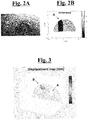
- the machinery 200 shown in Fig. 1 and 2A when turned on, result in objects with low coherence as they vibrate and move very fast with respect to the dimensions of the radar pixels and the scanning time, while the excavation face, for example a tunnel, moves slowly and consistently, and therefore is a highly coherent object.
- Fig. 2B it is possible to verify that the zone A, corresponding to the presence of machinery 200 in Fig. 2A , has pixels with low coherence (darker color) as opposed to the pixels of the surrounding zone.
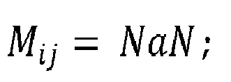
- Such mask coefficient value M ij can therefore determine the non-display of a pixel from the screen, for example, in the event that this pixel has insufficient power (static mask) or has a coherence coefficient value lower than the predetermined threshold for too long (dynamic mask).
- This filter in the display of the pixels on the screen 120 is defined as a "static" mask filter, since the aforesaid steps are not iterated at each cycle, but are carried out only when required on a specific image.
- the static mask filter can be realized both on the first acquired image of the scenario and on the following images, and it has an effect on all subsequent images, as long as a new calculation of the signal power is not made, if necessary.
- This calculation is carried out using an image acquired in the complete absence of machinery, in order to measure the signal strength at the excavation face.
- the static mask filter allows not to show the pixels with too low signal strength, which could give false positives, that is to report displacements that in reality are not taking place but which seem to take place due to a high background noise.
- This filter in the display of the pixels on the screen 120 is defined as a "dynamic" mask filter, since the aforesaid steps are iterated at each cycle, preventing the display of pixels considered as unreliable as they have had insufficient spatial coherence for several consecutive cycles.
- the static and dynamic mask filters therefore allow to view on the screen 120 only the truly reliable pixels, providing the operator with an immediate understanding of the reliability of the image.
- figure 3 it is possible to see a representation on the screen of the pixel displacement value projected on a three-dimensional map obtained by laser scanning of the scenario.
- zone A corresponds to a zone in which the pixels have low coherence and therefore are not displayed on the map
- zone B shows pixels that are having a high displacement.
- the pixels of zone B have high coherence; therefore, it can be excluded that it is a false positive and the measurement of the displacement is reliable.
Landscapes
- Engineering & Computer Science (AREA)
- Remote Sensing (AREA)
- Radar, Positioning & Navigation (AREA)
- Physics & Mathematics (AREA)
- General Physics & Mathematics (AREA)
- Computer Networks & Wireless Communication (AREA)
- Electromagnetism (AREA)
- Radar Systems Or Details Thereof (AREA)
- Length Measuring Devices By Optical Means (AREA)
- Geophysics And Detection Of Objects (AREA)
Abstract

Description
- The present invention relates to the field of monitoring the stability of an excavation face by means of SAR (Synthetic Aperture Radar) interferometry.
- In particular, the invention relates to a method for removing effects induced by moving objects in an interferometric image.
- As well known, in order to monitor the stability of the excavation faces, continuous monitoring devices based on laser technology are currently used. The purpose of these monitoring systems is to provide information on displacements and deformations that are precursors of a possible collapse of the excavation face in order to be able to stop the work by securing personnel and machinery.
- In most cases, these laser systems require the installation of optical reflectors that are fixed in correspondence with the areas to be monitored, measuring their position at regular intervals in order to detect any movement with an accuracy of about 1 mm.
- However, the installation of reflectors on the excavation face is not very easy due to the continuous processing operations and the continuous evolution of the face itself which force the periodic repositioning of the reflectors. In addition, laser-based systems are easily subject to measurement deterioration in the presence of dust or vapor resulting from excavation operations.
- An evolution of this measurement system is represented by the system called OBM, described in " Advanced observation techniques for sophisticated shallow tunnel projects-experience gained using innovative monitoring methods at the Lainzer Tunnel LT31" (Moritz Bernd et al., "Geomechanik a Tunnelbau: Geomechanik a Tunnelbau" 1.5, 2008, pp. 466-476), in which a total station is used without applying reflectors on the excavation face. Also, to keep the instrument lens dust-free, a fan is used that constantly blows towards the total station.
- However, this system has an accuracy of 2-4 mm, which is significantly lower than laser systems that use optical reflectors, with the risk of reducing the effectiveness of monitoring.
- An alternative solution is the use of an interferometric radar, a technology widely used for critical monitoring of landslides in the mining context. Radar interferometry provides displacement measurements with sub-millimeter accuracy and is therefore more effective in detecting the precursors of a possible collapse of the excavation face. At the same time, this technology is less prone to environmental disturbances such as dust and steam.
- However, this technology suffers from an important obstacle in case of application on an excavation face, i.e. the presence of disturbances due to machinery operating near the excavation face which produces deterioration of the quality of the radar data, with consequent ineffectiveness in monitoring movements.
- It is therefore an object of the present invention to provide a method for monitoring the stability of an excavation face by means of SAR interferometry which allows to detect displacements with sub-millimeter accuracy even in the presence of moving machinery.
- It is also an object of the present invention to provide such a method which allows to filter the interferometric data so as to preserve only the portion of information that can be used for the displacement measurement, avoiding the generation of false alarms due to any disturbances generated by machinery.
- It is still an object of the present invention to provide such a method which allows to combine laser measurements and radar interferometric measurements to provide a three-dimensional representation of the displacement data.
- These and other purposes are achieved by a method for filtering an interferometric radar acquisition, the method comprising the steps of:
- prearrangement of a radar system for carrying out acquisitions of images of a scenario by means of SAR interferometry, the radar system comprising:
- at least one radar sensor arranged to emit and receive a radar signal;
- a control unit configured to analyse the signal received by the radar sensor by means of interferometric technique;
- a screen arranged to show to a user the images of said scenario;
- by means of said radar system, periodic acquisition of images Si of the scenario for a number nc of cycles, with i = 1,2, ... ,nc, each image Si comprising a number np of pixels Pij having spatial coordinates defined with respect to a predetermined reference system, where Pij is the j-th pixel of the i-th image acquired at the i-th cycle, with j = 1,2,...,np .
- In particular, at each i-th cycle and for each pixel Pij, it is provided an iteration of the steps of:
- calculation of a coherence value γij arranged to represent the quality of the phase information supplied by a j-th pixel at the i-th cycle;
- comparison of the coherence value γij with a predetermined minimum coherence value γmin ;
- interferometric calculation of a displacement value dij of said pixel Pij, the displacement value dij being zero in case that in case that γij < γmin ;
- calculation of a cumulative displacement value Dij as the sum of the displacement values dij in the N cycles preceding said i-th cycle, the cumulative displacement value Dij being calculated according to the equation

- In particular, the coherence value γij is arranged to represent the degree of correlation of the phase information provided by a j-th pixel at the i-th cycle with the phase information provided by the same pixel in the previous cycle.
- Advantageously, each pixel Pij is associated with:
- a mask coefficient Mij arranged to assume a value Mij = NaN or a value Mij = 1, and wherein when Mij = NaN the pixel Pij is not shown on the screen and when Mij = 1 the pixel Pij is shown on the screen;
- a coherence coefficient mij arranged to assume a value mij = 0 in case that γij < γmin or a value mij = 1 in case that γij ≥ γmin.
- In particular, at each i-th cycle and for each pixel Pij, the steps are provided of:
- evaluation of the value of coherence coefficient mij in the N cycles preceding said i-th cycle;
- calculation of an over threshold fraction value fij as the sum of the values of the coherence coefficient mij in the N cycles preceding said i - th cycle divided the number of cycles N, the over threshold fraction value fij being calculated according to the equation

- comparison of the over threshold fraction value fij with a predetermined minimum over threshold fraction value fmin;
- in case that fij < fmin , assignment to the pixel Pij of a dynamic mask coefficient

- Advantageously, steps are provided of:
- calculation of a power value Wij for each pixel Pij of a predetermined image Si ;
- comparison, for each pixel Pij, of the power value Wij with a predetermined minimum power value Wmin ;
- in case that Wij < Wmin, assignment to the pixel Pij of a static mask coefficient

- in case that Wij ≥ Wmin, assignment to the pixel Pij of a static coefficient of mask

- More in particular, following conditions are valid:
- if


- if


- if


- if


- Advantageously, steps are provided of:
- laser scanning with obtaining a three-dimensional map of the scenario;
- projection of each cumulative displacement value Dij on the three-dimensional map of the scenario obtained by the step of laser scanning.
- In particular, the radar system is adapted to emit an alarm in case that a cumulative displacement value Dij exceeds a predetermined threshold Dmax.
- Advantageously, a step is provided of calculation of the number q of pixels Pij having mask coefficient Mij = NaN, the radar system being adapted to emit an alarm in case that the ratio q/np exceeds a predetermined threshold.
- Advantageously, at each i-th cycle and for each pixel Pij, the steps are provided of:
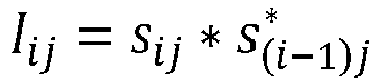
- calculation of an interferogram Iij of the pixel Pij according to the equation


- interferometric calculation of the displacement value dij as a function of arg[Iij ], wherein arg[Iij ] is the argument of the complex number Iij .
- In particular, the displacement value dij is calculated according to the equation

- Advantageously, the coherence value γij is a spatial coherence value and it is calculated by the equation:


- Further characteristic and/or advantages of the present invention are more bright with the following description of an exemplary embodiment thereof, exemplifying but not limitative, with reference to the attached drawings in which:
-
Fig. 1A schematically shows a radar system during the monitoring of an excavation face; -
Fig. 1B shows in detail the screen arranged to show the images of the scenario; -
Fig. 2A shows an optical image of a scenario inside a tunnel in which excavation operations are carried out; -
Fig. 2B shows by variation of color intensity a representation of the coherence value of the pixels corresponding to the interferometric image relating to the scenario ofFigure 2A ; -
Fig. 3 shows shows by variation of color intensity a representation of the pixel displacement value projected on a three-dimensional map obtained by laser scanning; -
Fig. 4 shows a flow diagram of a possible embodiment of the method according to the present invention; -
Fig. 5 shows a flow diagram of a possible variant embodiment of the method according to the present invention. - With reference to
Figs. 1 and4 , in a possible embodiment of the present invention, the method for filtering an interferometric radar acquisition comprises a first step of prearranging a radar system arranged to provide acquisitions of images of the scenario by means of SAR interferometry. In particular, the radar system comprises at least oneradar sensor 110 arranged to emit and receive a radar signal and ascreen 120 arranged to show the images of the scenario. The radar system also comprises acontrol unit 115 configured to analyse the received signal by theradar sensor 110 by means of interferometric technique and to send images to thescreen 120. - The method then provides a step, by means of the radar system, of periodic acquisition of images Si of the scenario for a number nc of cycles, with i = 1,2, ..., nc. Each image Si comprises a number np of pixels Pij having spatial coordinates defined with respect to a predetermined reference system, where Pij is the j-th pixel of the i-th image acquired at the i-th cycle, with j = 1,2,..., np .
- The method then provides a processing, by means of the control unit, of the acquired images by carrying out an iteration of the following steps at each i-th cycle and for each pixel Pij .
- There is a first step of calculation of the interferogram of a relative pixel Pij according to the equation:

- There is then a step of calculation of a coherence value γij arranged to represent the quality of the phase information supplied by the j-th pixel at the i-th cycle. In particular, the coherence value γij is arranged to represent the degree of correlation of the phase information provided by a j-th pixel at the i-th cycle with the phase information provided by the same pixel in the previous cycle.
- In one embodiment of the invention, the coherence value can be a spatial coherence value calculated considering the cycle i-th and the previous cycle by the equation:

- In a subsequent step, the calculated spatial coherence value γij is compared with a predetermined minimum spatial coherence value γmin. Each pixel Pij is also associated with a coherence coefficient mij which can assume a value mij = 0 or a value mij = 1.
- In case that γij < γmin, a coherence coefficient value mij = 0 is assigned to said pixel Pij, whereas, in case that γij ≥ γmin, a coherence coefficient value mij = 1 is assigned to said pixel Pij .
- There is then a step of interferometric calculation of a displacement value dij of each pixel Pij according to the equation:
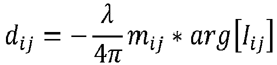
- As verifiable by the previous equation, displacement value dij is zero in case that mij = 0.
- Finally, there is a step of calculation of a cumulative displacement value Dij as the sum of the displacement values dij in the N cycles preceding the i-th cycle, i.e. according to the equation:

- The method claimed in the present invention, therefore, by assigning a unitary or null value to the coherence coefficient mij associated with each pixel Pij, allows to exclude from the calculation of the cumulative displacement Dij the pixels that do not have sufficient coherence, i.e. not reliable due to movements of objects with low coherence within the scenario.
- For example, the
machinery 200 shown inFig. 1 and2A , when turned on, result in objects with low coherence as they vibrate and move very fast with respect to the dimensions of the radar pixels and the scanning time, while the excavation face, for example a tunnel, moves slowly and consistently, and therefore is a highly coherent object. InFig. 2B it is possible to verify that the zone A, corresponding to the presence ofmachinery 200 inFig. 2A , has pixels with low coherence (darker color) as opposed to the pixels of the surrounding zone. - With reference even at
Fig. 5 , in a variant embodiment of the method according to the present invention, there is also provided an association to each pixel Pij of a mask coefficient Mij arranged to assume a value Mij = NaN or a value Mij =1, in such a way that the pixel Pij is not shown on thescreen 120 when Mij = NaN and is instead shown when Mij = 1. - Such mask coefficient value Mij can therefore determine the non-display of a pixel from the screen, for example, in the event that this pixel has insufficient power (static mask) or has a coherence coefficient value lower than the predetermined threshold for too long (dynamic mask).
- In particular, in this variant embodiment, the method provides a static mask filter implemented by means of a first step of calculation of a power value Wij for each pixel Pij of a predetermined image Si , a step of comparison of this power value Wij with a predetermined minimum power value Wmin and, in case that Wij < Wmin, an assignment to the pixel Pij of a static mask coefficient

- This filter in the display of the pixels on the
screen 120 is defined as a "static" mask filter, since the aforesaid steps are not iterated at each cycle, but are carried out only when required on a specific image. For example, the static mask filter can be realized both on the first acquired image of the scenario and on the following images, and it has an effect on all subsequent images, as long as a new calculation of the signal power is not made, if necessary. - This calculation is carried out using an image acquired in the complete absence of machinery, in order to measure the signal strength at the excavation face. The static mask filter allows not to show the pixels with too low signal strength, which could give false positives, that is to report displacements that in reality are not taking place but which seem to take place due to a high background noise.
- Still with reference to
Fig. 5 , in this embodiment variante, the method also comprises a dynamic mask filter implemented by an iteration at each i-th cycle and for each pixel Pij of a first step of evaluation of coherence coefficient value mij in the N cycles preceding the i-th cycle. Then follows a step of calculation of an over threshold fraction value fij as the sum of the values of coherence coefficient mij in the N cycles preceding the i-th cycle divided by the number of cycles N, i.e. by means of the equation:
- There is therefore a step of comparison of the over threshold fraction value fij with a predetermined minimum over threshold fraction value fmin and, in case that fij < fmin , an assignment to the pixel Pij of a dynamic mask coefficient


- This filter in the display of the pixels on the
screen 120 is defined as a "dynamic" mask filter, since the aforesaid steps are iterated at each cycle, preventing the display of pixels considered as unreliable as they have had insufficient spatial coherence for several consecutive cycles. - This allows to exclude from the image pixels that could give false negatives, that is to report that no movements are taking place, when in reality they are happening.
- As schematized in
Fig. 5 , if one of the conditions


screen 120. - The static and dynamic mask filters therefore allow to view on the
screen 120 only the truly reliable pixels, providing the operator with an immediate understanding of the reliability of the image. Infigure 3 it is possible to see a representation on the screen of the pixel displacement value projected on a three-dimensional map obtained by laser scanning of the scenario. In particular, zone A corresponds to a zone in which the pixels have low coherence and therefore are not displayed on the map, while zone B shows pixels that are having a high displacement. The pixels of zone B have high coherence; therefore, it can be excluded that it is a false positive and the measurement of the displacement is reliable. - The foregoing description some exemplary specific embodiments will so fully reveal the invention according to the conceptual point of view, so that others, by applying current knowledge, will be able to modify and/or adapt in various applications the specific exemplary embodiments without further research and without parting from the invention, and, accordingly, it is meant that such adaptations and modifications will have to be considered as equivalent to the specific embodiments. The means and the materials to realise the different functions described herein could have a different nature without, for this reason, departing from the field of the invention. it is to be understood that the phraseology or terminology that is employed herein is for the purpose of description and not of limitation.
Claims (11)
- A method for filtering an interferometric radar acquisition, said method comprising the steps of:- prearrangement of a radar system for carrying out acquisitions of images of a scenario by means of SAR interferometry, said radar system comprising:- at least one radar sensor (110) arranged to emit and receive a radar signal;- a control unit (115) configured to analyse said signal received by said radar sensor (110) by means of interferometric technique;- a screen (120) arranged to show to a user said images of said scenario;- by means of said radar system, periodic acquisition of images Si of said scenario for a number nc of cycles, with i=1,2,...,nc, each image Si comprising a number np of pixels Pij having spatial coordinates defined with respect to a predetermined reference system, where Pij is the j-th pixel of the i-th image acquired at the i-th cycle, with j = 1,2,...,np;said method characterized in that, at each i-th cycle and for each pixel Pij , it is provided an iteration of the steps of:- calculation of a coherence value γij arranged to represent the quality of the phase information supplied by a j-th pixel at the i-th cycle;- comparison of said coherence value γij with a predetermined minimum coherence value γmin ;- interferometric calculation of a displacement value dij of said pixel Pij, said displacement value dij being zero in case that in case that γij < γmin ;- calculation of a cumulative displacement value Dij as the sum of the displacement values dij in the N cycles preceding said i-th cycle, said cumulative displacement value Dij being calculated according to the equation

- A method for filtering an interferometric radar acquisition, according to claim 1, wherein each pixel Pij is associated with:- a mask coefficient Mij arranged to assume a value Mij = NaN or a value Mij =1, and wherein when Mij = NaN said pixel Pij is not shown on said screen (120) and when Mij = 1 said pixel Pij is shown on said screen (120);- a coherence coefficient mij arranged to assume a value mij = 0 in case that γij < γmin or a value mij = 1 in case that γij ≥ γmin.
- A method for filtering an interferometric radar acquisition, according to claim 2, wherein, at each i-th cycle and for each pixel Pij, the steps are provided of:- evaluation of said value of coherence coefficient mij in the N cycles preceding said i-th cycle;- calculation of an over threshold fraction value fij as the sum of the values of the coherence coefficient mij in the N cycles preceding said i-th cycle divided the number of cycles N, said over threshold fraction value fij being calculated according to the equation
 - comparison of said over threshold fraction value fij with a predetermined minimum over threshold fraction value fmin ;- in case that fij < fmin , assignment to said pixel Pij of a dynamic mask coefficient
- A method for filtering an interferometric radar acquisition, according to claim 2, where the steps are provided of:- calculation of a power value Wij for each pixel Pij of a predetermined image Si ;- comparison, for each pixel Pij , of said power value Wij with a predetermined minimum power value Wmin ;- in case that Wij < Wmin, assignment to said pixel Pij of a static mask coefficient
 - in case that Wij ≥ Wmin, assignment to said pixel Pij of a static coefficient of mask
- A method for filtering an interferometric radar acquisition, according to claims 3 and 4, wherein:- if


 - if
- if

 - if
- if

 - if
- if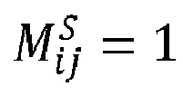


- A method for filtering an interferometric radar acquisition, according to claim 1, wherein steps are provided of:- laser scanning with obtaining a three-dimensional map of said scenario;- projection of each cumulative displacement value Dij on said three-dimensional map of said scenario obtained by said step of laser scanning.
- A method for filtering an interferometric radar acquisition, according to claim 1, wherein said radar system is adapted to emit an alarm in case that a cumulative displacement value Dij exceeds a predetermined threshold Dmax.
- A method for filtering an interferometric radar acquisition, according to claim 2, wherein a step is provided of calculation of the number q of pixels Pij having mask coefficient Mij = NaN and wherein said radar system is adapted to emit an alarm in case that the ratio q/np exceeds a predetermined threshold.
- A method for filtering an interferometric radar acquisition, according to claim 1, wherein, at each i-th cycle and for each pixel Pij, the steps are provided of:- calculation of an interferogram Iij of said pixel Pij according to the equation

 - interferometric calculation of said displacement value dij as a function of arg[Iij ], wherein arg[Iij ] is the argument of the complex number Iij .
 - A method for filtering an interferometric radar acquisition, according to claims 2 and 9, wherein, said displacement value dij is calculated according to the equation

- A method for filtering an interferometric radar acquisition, according to claim 1, wherein said coherence value γij is a spatial coherence value and it is calculated by the equation:
 where 〈〉 spat is a spatial media mathematical operator operating in a neighbourhood of the j-th pixel,and where sij is the complex number representing the focused radar data of the j-th pixel of the i-th image and
Applications Claiming Priority (1)
| Application Number | Priority Date | Filing Date | Title |
|---|---|---|---|
| IT102020000008110A IT202000008110A1 (en) | 2020-04-16 | 2020-04-16 | Method for monitoring the stability of an excavation face by radar interferometry |
Publications (2)
| Publication Number | Publication Date |
|---|---|
| EP3896486A1 true EP3896486A1 (en) | 2021-10-20 |
| EP3896486B1 EP3896486B1 (en) | 2025-06-04 |
Family
ID=71452578
Family Applications (1)
| Application Number | Title | Priority Date | Filing Date |
|---|---|---|---|
| EP21168719.9A Active EP3896486B1 (en) | 2020-04-16 | 2021-04-15 | Method for monitoring the stability of an excavation front using radar interferometry |
Country Status (6)
| Country | Link |
|---|---|
| US (1) | US11555886B2 (en) |
| EP (1) | EP3896486B1 (en) |
| JP (1) | JP7708576B2 (en) |
| CN (1) | CN113534147A (en) |
| AU (1) | AU2021201855B2 (en) |
| IT (1) | IT202000008110A1 (en) |
Families Citing this family (1)
| Publication number | Priority date | Publication date | Assignee | Title |
|---|---|---|---|---|
| CN115824813B (en) * | 2023-02-23 | 2023-05-09 | 叙镇铁路有限责任公司 | Test device and method for testing range of surrounding rock plastic zone caused by tunnel excavation |
Citations (3)
| Publication number | Priority date | Publication date | Assignee | Title |
|---|---|---|---|---|
| WO2010000870A1 (en) * | 2008-07-04 | 2010-01-07 | Telespazio S.P.A. | Identification and analysis of persistent scatterers in series of sar images |
| EP2413158A1 (en) * | 2010-07-26 | 2012-02-01 | Consorci Institut de Geomatica | A method for monitoring terrain and man-made feature displacements using ground-based synthetic aperture radar (GBSAR) data |
| CN108627834A (en) * | 2018-06-07 | 2018-10-09 | 北京城建勘测设计研究院有限责任公司 | A kind of subway road structure monitoring method and device based on ground InSAR |
Family Cites Families (2)
| Publication number | Priority date | Publication date | Assignee | Title |
|---|---|---|---|---|
| US6011505A (en) * | 1996-07-11 | 2000-01-04 | Science Applications International Corporation | Terrain elevation measurement by interferometric synthetic aperture radar (IFSAR) |
| WO2020240720A1 (en) * | 2019-05-29 | 2020-12-03 | 日本電気株式会社 | Synthetic aperture radar signal processing device and signal processing method |
-
2020
- 2020-04-16 IT IT102020000008110A patent/IT202000008110A1/en unknown
-
2021
- 2021-03-24 AU AU2021201855A patent/AU2021201855B2/en active Active
- 2021-04-13 JP JP2021067642A patent/JP7708576B2/en active Active
- 2021-04-14 CN CN202110399721.4A patent/CN113534147A/en active Pending
- 2021-04-15 US US17/231,929 patent/US11555886B2/en active Active
- 2021-04-15 EP EP21168719.9A patent/EP3896486B1/en active Active
Patent Citations (3)
| Publication number | Priority date | Publication date | Assignee | Title |
|---|---|---|---|---|
| WO2010000870A1 (en) * | 2008-07-04 | 2010-01-07 | Telespazio S.P.A. | Identification and analysis of persistent scatterers in series of sar images |
| EP2413158A1 (en) * | 2010-07-26 | 2012-02-01 | Consorci Institut de Geomatica | A method for monitoring terrain and man-made feature displacements using ground-based synthetic aperture radar (GBSAR) data |
| CN108627834A (en) * | 2018-06-07 | 2018-10-09 | 北京城建勘测设计研究院有限责任公司 | A kind of subway road structure monitoring method and device based on ground InSAR |
Non-Patent Citations (2)
| Title |
|---|
| FORNARO G ET AL: "Inversion of Wrapped Differential Interferometric SAR Data for Fault Dislocation Modeling", IEEE TRANSACTIONS ON GEOSCIENCE AND REMOTE SENSING, IEEE SERVICE CENTER, PISCATAWAY, NJ, US, vol. 50, no. 6, 1 June 2012 (2012-06-01), pages 2175 - 2184, XP011444369, ISSN: 0196-2892, DOI: 10.1109/TGRS.2011.2173584 * |
| MORITZ BERND ET AL.: "Advanced observation techniques for sophisticated shallow tunnel projects-experience gained using innovative monitoring methods at the Lainzer Tunnel LT31", GEOMECHANIK A TUNNELBAU: GEOMECHANIK A TUNNELBAU, vol. 1.5, 2008, pages 466 - 476 |
Also Published As
| Publication number | Publication date |
|---|---|
| CN113534147A (en) | 2021-10-22 |
| JP2021170004A (en) | 2021-10-28 |
| US11555886B2 (en) | 2023-01-17 |
| AU2021201855A1 (en) | 2021-11-04 |
| US20210325511A1 (en) | 2021-10-21 |
| AU2021201855B2 (en) | 2026-07-02 |
| EP3896486B1 (en) | 2025-06-04 |
| IT202000008110A1 (en) | 2021-10-16 |
| JP7708576B2 (en) | 2025-07-15 |
Similar Documents
| Publication | Publication Date | Title |
|---|---|---|
| EP3362816B2 (en) | Slope stability lidar | |
| US7092106B2 (en) | System for determining the configuration of obscured structure by employing phase profilometry and method of use therefor | |
| US6850183B2 (en) | Slope monitoring system | |
| US20220333956A1 (en) | Mapping using optical fiber sensing | |
| CN106872994B (en) | A kind of laser radar scanning method and device | |
| AU2002218070A1 (en) | Slope monitoring system | |
| JP2023538474A (en) | Anomaly detection based on statistical image processing to prevent cable breakage | |
| EP3896486B1 (en) | Method for monitoring the stability of an excavation front using radar interferometry | |
| EP0928465B1 (en) | Detection system | |
| SE543108C2 (en) | Method and device for inspection of a geometry, the device comprising image capturing and shape scanning means | |
| JP2023091582A (en) | tunnel face warning system | |
| CN115755069B (en) | A foreign object detection device, detection system and detection method for railway tracks | |
| US10318798B2 (en) | Device and method for detecting non-visible content in a non-contact manner | |
| JP3592962B2 (en) | Abnormal object monitoring device | |
| CN116952203A (en) | Method for coordinated measurement by ground scanning with image-based disturbance detection of moving objects | |
| US8270678B2 (en) | Method, system, and computer program product to detect micron scale displacement of objects from a long range with and optical device and related computer implemented methods | |
| KR20230094678A (en) | Motion amplification devices and methods of using thereof | |
| KR102886753B1 (en) | Spatial analysis system and method for robot | |
| US12190593B2 (en) | Imaging device | |
| Fahle et al. | Evaluation of SLAM-based mobile lidar workflows and data quality for mine-wide underground geotechnical monitoring | |
| JP2024074198A (en) | Underground work scoring device and scoring method | |
| JP2024049991A (en) | Underground work safety management system | |
| JP2026067152A (en) | Face Safety Management System | |
| Coetsee et al. | Establishing a successful pit slope monitoring database using Ground Based Radars (GBR) | |
| Frish | Position/Organization: Manager, Industrial Sensors/Physical Sciences Inc. Session Title: Distribution: 6.(TIC) Advances in gas distribution practices Paper Title: Monitoring fugitive methane emissions utilizing advanced small unmanned aerial sensor technology Co-authors: Nicholas F. Aubut, Matthew C. Laderer, Physical Sciences Inc. |
Legal Events
| Date | Code | Title | Description |
|---|---|---|---|
| PUAI | Public reference made under article 153(3) epc to a published international application that has entered the european phase |
Free format text: ORIGINAL CODE: 0009012 |
|
| STAA | Information on the status of an ep patent application or granted ep patent |
Free format text: STATUS: THE APPLICATION HAS BEEN PUBLISHED |
|
| AK | Designated contracting states |
Kind code of ref document: A1 Designated state(s): AL AT BE BG CH CY CZ DE DK EE ES FI FR GB GR HR HU IE IS IT LI LT LU LV MC MK MT NL NO PL PT RO RS SE SI SK SM TR |
|
| B565 | Issuance of search results under rule 164(2) epc |
Effective date: 20210909 |
|
| STAA | Information on the status of an ep patent application or granted ep patent |
Free format text: STATUS: REQUEST FOR EXAMINATION WAS MADE |
|
| 17P | Request for examination filed |
Effective date: 20220325 |
|
| RBV | Designated contracting states (corrected) |
Designated state(s): AL AT BE BG CH CY CZ DE DK EE ES FI FR GB GR HR HU IE IS IT LI LT LU LV MC MK MT NL NO PL PT RO RS SE SI SK SM TR |
|
| GRAP | Despatch of communication of intention to grant a patent |
Free format text: ORIGINAL CODE: EPIDOSNIGR1 |
|
| STAA | Information on the status of an ep patent application or granted ep patent |
Free format text: STATUS: GRANT OF PATENT IS INTENDED |
|
| INTG | Intention to grant announced |
Effective date: 20241115 |
|
| GRAS | Grant fee paid |
Free format text: ORIGINAL CODE: EPIDOSNIGR3 |
|
| GRAA | (expected) grant |
Free format text: ORIGINAL CODE: 0009210 |
|
| STAA | Information on the status of an ep patent application or granted ep patent |
Free format text: STATUS: THE PATENT HAS BEEN GRANTED |
|
| AK | Designated contracting states |
Kind code of ref document: B1 Designated state(s): AL AT BE BG CH CY CZ DE DK EE ES FI FR GB GR HR HU IE IS IT LI LT LU LV MC MK MT NL NO PL PT RO RS SE SI SK SM TR |
|
| REG | Reference to a national code |
Ref country code: GB Ref legal event code: FG4D |
|
| REG | Reference to a national code |
Ref country code: CH Ref legal event code: EP |
|
| REG | Reference to a national code |
Ref country code: DE Ref legal event code: R096 Ref document number: 602021031608 Country of ref document: DE |
|
| REG | Reference to a national code |
Ref country code: IE Ref legal event code: FG4D |
|
| REG | Reference to a national code |
Ref country code: NL Ref legal event code: MP Effective date: 20250604 |
|
| PG25 | Lapsed in a contracting state [announced via postgrant information from national office to epo] |
Ref country code: ES Free format text: LAPSE BECAUSE OF FAILURE TO SUBMIT A TRANSLATION OF THE DESCRIPTION OR TO PAY THE FEE WITHIN THE PRESCRIBED TIME-LIMIT Effective date: 20250604 Ref country code: FI Free format text: LAPSE BECAUSE OF FAILURE TO SUBMIT A TRANSLATION OF THE DESCRIPTION OR TO PAY THE FEE WITHIN THE PRESCRIBED TIME-LIMIT Effective date: 20250604 |
|
| REG | Reference to a national code |
Ref country code: LT Ref legal event code: MG9D |
|
| PG25 | Lapsed in a contracting state [announced via postgrant information from national office to epo] |
Ref country code: GR Free format text: LAPSE BECAUSE OF FAILURE TO SUBMIT A TRANSLATION OF THE DESCRIPTION OR TO PAY THE FEE WITHIN THE PRESCRIBED TIME-LIMIT Effective date: 20250905 Ref country code: NO Free format text: LAPSE BECAUSE OF FAILURE TO SUBMIT A TRANSLATION OF THE DESCRIPTION OR TO PAY THE FEE WITHIN THE PRESCRIBED TIME-LIMIT Effective date: 20250904 |
|
| PG25 | Lapsed in a contracting state [announced via postgrant information from national office to epo] |
Ref country code: PL Free format text: LAPSE BECAUSE OF FAILURE TO SUBMIT A TRANSLATION OF THE DESCRIPTION OR TO PAY THE FEE WITHIN THE PRESCRIBED TIME-LIMIT Effective date: 20250604 |
|
| PG25 | Lapsed in a contracting state [announced via postgrant information from national office to epo] |
Ref country code: BG Free format text: LAPSE BECAUSE OF FAILURE TO SUBMIT A TRANSLATION OF THE DESCRIPTION OR TO PAY THE FEE WITHIN THE PRESCRIBED TIME-LIMIT Effective date: 20250604 |
|
| PG25 | Lapsed in a contracting state [announced via postgrant information from national office to epo] |
Ref country code: HR Free format text: LAPSE BECAUSE OF FAILURE TO SUBMIT A TRANSLATION OF THE DESCRIPTION OR TO PAY THE FEE WITHIN THE PRESCRIBED TIME-LIMIT Effective date: 20250604 |
|
| PG25 | Lapsed in a contracting state [announced via postgrant information from national office to epo] |
Ref country code: RS Free format text: LAPSE BECAUSE OF FAILURE TO SUBMIT A TRANSLATION OF THE DESCRIPTION OR TO PAY THE FEE WITHIN THE PRESCRIBED TIME-LIMIT Effective date: 20250904 |
|
| PG25 | Lapsed in a contracting state [announced via postgrant information from national office to epo] |
Ref country code: LV Free format text: LAPSE BECAUSE OF FAILURE TO SUBMIT A TRANSLATION OF THE DESCRIPTION OR TO PAY THE FEE WITHIN THE PRESCRIBED TIME-LIMIT Effective date: 20250604 |
|
| PG25 | Lapsed in a contracting state [announced via postgrant information from national office to epo] |
Ref country code: NL Free format text: LAPSE BECAUSE OF FAILURE TO SUBMIT A TRANSLATION OF THE DESCRIPTION OR TO PAY THE FEE WITHIN THE PRESCRIBED TIME-LIMIT Effective date: 20250604 |
|
| PG25 | Lapsed in a contracting state [announced via postgrant information from national office to epo] |
Ref country code: PT Free format text: LAPSE BECAUSE OF FAILURE TO SUBMIT A TRANSLATION OF THE DESCRIPTION OR TO PAY THE FEE WITHIN THE PRESCRIBED TIME-LIMIT Effective date: 20251006 |
|
| REG | Reference to a national code |
Ref country code: AT Ref legal event code: MK05 Ref document number: 1800838 Country of ref document: AT Kind code of ref document: T Effective date: 20250604 |
|
| PG25 | Lapsed in a contracting state [announced via postgrant information from national office to epo] |
Ref country code: IS Free format text: LAPSE BECAUSE OF FAILURE TO SUBMIT A TRANSLATION OF THE DESCRIPTION OR TO PAY THE FEE WITHIN THE PRESCRIBED TIME-LIMIT Effective date: 20251004 |
|
| PG25 | Lapsed in a contracting state [announced via postgrant information from national office to epo] |
Ref country code: AT Free format text: LAPSE BECAUSE OF FAILURE TO SUBMIT A TRANSLATION OF THE DESCRIPTION OR TO PAY THE FEE WITHIN THE PRESCRIBED TIME-LIMIT Effective date: 20250604 Ref country code: SM Free format text: LAPSE BECAUSE OF FAILURE TO SUBMIT A TRANSLATION OF THE DESCRIPTION OR TO PAY THE FEE WITHIN THE PRESCRIBED TIME-LIMIT Effective date: 20250604 |
|
| PG25 | Lapsed in a contracting state [announced via postgrant information from national office to epo] |
Ref country code: CZ Free format text: LAPSE BECAUSE OF FAILURE TO SUBMIT A TRANSLATION OF THE DESCRIPTION OR TO PAY THE FEE WITHIN THE PRESCRIBED TIME-LIMIT Effective date: 20250604 |
|
| PG25 | Lapsed in a contracting state [announced via postgrant information from national office to epo] |
Ref country code: EE Free format text: LAPSE BECAUSE OF FAILURE TO SUBMIT A TRANSLATION OF THE DESCRIPTION OR TO PAY THE FEE WITHIN THE PRESCRIBED TIME-LIMIT Effective date: 20250604 |
|
| PG25 | Lapsed in a contracting state [announced via postgrant information from national office to epo] |
Ref country code: RO Free format text: LAPSE BECAUSE OF FAILURE TO SUBMIT A TRANSLATION OF THE DESCRIPTION OR TO PAY THE FEE WITHIN THE PRESCRIBED TIME-LIMIT Effective date: 20250604 Ref country code: SK Free format text: LAPSE BECAUSE OF FAILURE TO SUBMIT A TRANSLATION OF THE DESCRIPTION OR TO PAY THE FEE WITHIN THE PRESCRIBED TIME-LIMIT Effective date: 20250604 |
|
| PG25 | Lapsed in a contracting state [announced via postgrant information from national office to epo] |
Ref country code: IT Free format text: LAPSE BECAUSE OF FAILURE TO SUBMIT A TRANSLATION OF THE DESCRIPTION OR TO PAY THE FEE WITHIN THE PRESCRIBED TIME-LIMIT Effective date: 20250604 |
|
| REG | Reference to a national code |
Ref country code: DE Ref legal event code: R097 Ref document number: 602021031608 Country of ref document: DE |
|
| PLBE | No opposition filed within time limit |
Free format text: ORIGINAL CODE: 0009261 |
|
| STAA | Information on the status of an ep patent application or granted ep patent |
Free format text: STATUS: NO OPPOSITION FILED WITHIN TIME LIMIT |
|
| PG25 | Lapsed in a contracting state [announced via postgrant information from national office to epo] |
Ref country code: DK Free format text: LAPSE BECAUSE OF FAILURE TO SUBMIT A TRANSLATION OF THE DESCRIPTION OR TO PAY THE FEE WITHIN THE PRESCRIBED TIME-LIMIT Effective date: 20250604 |
|
| REG | Reference to a national code |
Ref country code: CH Ref legal event code: L10 Free format text: ST27 STATUS EVENT CODE: U-0-0-L10-L00 (AS PROVIDED BY THE NATIONAL OFFICE) Effective date: 20260416 |
|
| REG | Reference to a national code |
Ref country code: CH Ref legal event code: U11 Free format text: ST27 STATUS EVENT CODE: U-0-0-U10-U11 (AS PROVIDED BY THE NATIONAL OFFICE) Effective date: 20260501 |
|
| 26N | No opposition filed |
Effective date: 20260305 |
|
| PG25 | Lapsed in a contracting state [announced via postgrant information from national office to epo] |
Ref country code: LT Free format text: LAPSE BECAUSE OF FAILURE TO SUBMIT A TRANSLATION OF THE DESCRIPTION OR TO PAY THE FEE WITHIN THE PRESCRIBED TIME-LIMIT Effective date: 20250604 |
|
| PGFP | Annual fee paid to national office [announced via postgrant information from national office to epo] |
Ref country code: DE Payment date: 20260429 Year of fee payment: 6 |
|
| PGFP | Annual fee paid to national office [announced via postgrant information from national office to epo] |
Ref country code: CH Payment date: 20260501 Year of fee payment: 6 |
|
| PGFP | Annual fee paid to national office [announced via postgrant information from national office to epo] |
Ref country code: FR Payment date: 20260421 Year of fee payment: 6 |
|
| PG25 | Lapsed in a contracting state [announced via postgrant information from national office to epo] |
Ref country code: SE Free format text: LAPSE BECAUSE OF FAILURE TO SUBMIT A TRANSLATION OF THE DESCRIPTION OR TO PAY THE FEE WITHIN THE PRESCRIBED TIME-LIMIT Effective date: 20250604 |