EP3896468B1 - Platform for testing leakage current difference factor of aged xlpe cable, and method - Google Patents
Platform for testing leakage current difference factor of aged xlpe cable, and method Download PDFInfo
- Publication number
- EP3896468B1 EP3896468B1 EP20890914.3A EP20890914A EP3896468B1 EP 3896468 B1 EP3896468 B1 EP 3896468B1 EP 20890914 A EP20890914 A EP 20890914A EP 3896468 B1 EP3896468 B1 EP 3896468B1
- Authority
- EP
- European Patent Office
- Prior art keywords
- current
- leakage
- cable
- frequency
- data
- Prior art date
- Legal status (The legal status is an assumption and is not a legal conclusion. Google has not performed a legal analysis and makes no representation as to the accuracy of the status listed.)
- Active
Links
Images
Classifications
-
- G—PHYSICS
- G01—MEASURING; TESTING
- G01R—MEASURING ELECTRIC VARIABLES; MEASURING MAGNETIC VARIABLES
- G01R31/00—Arrangements for testing electric properties; Arrangements for locating electric faults; Arrangements for electrical testing characterised by what is being tested not provided for elsewhere
- G01R31/12—Testing dielectric strength or breakdown voltage ; Testing or monitoring effectiveness or level of insulation, e.g. of a cable or of an apparatus, for example using partial discharge measurements; Electrostatic testing
- G01R31/1227—Testing dielectric strength or breakdown voltage ; Testing or monitoring effectiveness or level of insulation, e.g. of a cable or of an apparatus, for example using partial discharge measurements; Electrostatic testing of components, parts or materials
- G01R31/1263—Testing dielectric strength or breakdown voltage ; Testing or monitoring effectiveness or level of insulation, e.g. of a cable or of an apparatus, for example using partial discharge measurements; Electrostatic testing of components, parts or materials of solid or fluid materials, e.g. insulation films, bulk material; of semiconductors or LV electronic components or parts; of cable, line or wire insulation
- G01R31/1272—Testing dielectric strength or breakdown voltage ; Testing or monitoring effectiveness or level of insulation, e.g. of a cable or of an apparatus, for example using partial discharge measurements; Electrostatic testing of components, parts or materials of solid or fluid materials, e.g. insulation films, bulk material; of semiconductors or LV electronic components or parts; of cable, line or wire insulation of cable, line or wire insulation, e.g. using partial discharge measurements
-
- G—PHYSICS
- G01—MEASURING; TESTING
- G01R—MEASURING ELECTRIC VARIABLES; MEASURING MAGNETIC VARIABLES
- G01R19/00—Arrangements for measuring currents or voltages or for indicating presence or sign thereof
- G01R19/0092—Measuring current only
-
- G—PHYSICS
- G01—MEASURING; TESTING
- G01R—MEASURING ELECTRIC VARIABLES; MEASURING MAGNETIC VARIABLES
- G01R31/00—Arrangements for testing electric properties; Arrangements for locating electric faults; Arrangements for electrical testing characterised by what is being tested not provided for elsewhere
- G01R31/003—Environmental or reliability tests
-
- G—PHYSICS
- G01—MEASURING; TESTING
- G01R—MEASURING ELECTRIC VARIABLES; MEASURING MAGNETIC VARIABLES
- G01R31/00—Arrangements for testing electric properties; Arrangements for locating electric faults; Arrangements for electrical testing characterised by what is being tested not provided for elsewhere
- G01R31/50—Testing of electric apparatus, lines, cables or components for short-circuits, continuity, leakage current or incorrect line connections
- G01R31/52—Testing for short-circuits, leakage current or ground faults
-
- G—PHYSICS
- G01—MEASURING; TESTING
- G01R—MEASURING ELECTRIC VARIABLES; MEASURING MAGNETIC VARIABLES
- G01R31/00—Arrangements for testing electric properties; Arrangements for locating electric faults; Arrangements for electrical testing characterised by what is being tested not provided for elsewhere
- G01R31/50—Testing of electric apparatus, lines, cables or components for short-circuits, continuity, leakage current or incorrect line connections
- G01R31/58—Testing of lines, cables or conductors
Definitions
- the present invention relates to the field of evaluating an insulating deterioration state of an XLPE cable, and in particular, to a platform and method for measuring a leakage-current difference factor of a deteriorated XLPE cable.
- Cross linked polyethylene is widely used in modern urban distribution networks, and has a lot of advantages, such as high reliability of power supply, good insulation performance, good water resistance and chemical corrosion resistance.
- the XLPE has a disadvantage that cracks are easily generated under mechanical stress.
- the cable may deteriorate as service time goes by. Therefore, to improve reliability of power supply, it is very important to evaluate a deterioration state of the cable.
- This method is a platform and method for measuring a leakage-current difference factor of a deteriorated XLPE cable. This method is simple to operate and can effectively evaluate the deterioration state of the cable by calculating detected leakage current.
- the document "Investigation of high frequency signal propagation characteristics on HV XLPE cables, O H N et. al.” discloses a cable testing platform for detecting partial discharges at the dielectric of XLPE cables, and further discloses a method of testing an XLPE cable, the method comprising obtaining current data and calculating a leakage current difference factor, wherein the leakage current difference factor is the ratio of the currents between the two ends of the cable.
- An objective of the present invention is to provide a platform and method for measuring a leakage-current difference factor of a deteriorated XLPE cable, to judge an insulation deterioration state of an XLPE cable in long-term operation of urban distribution networks. This method is simple to operate and can effectively evaluate the deterioration state of the cable by calculating detected leakage current.
- this application provides a platform and method for measuring a leakage-current difference factor of a deteriorated XLPE cable.
- the cable leakage current testing platform is first established to test leakage current of an XLPE cable in long-term operation; subsequently, the leakage-current characteristic parameter, the disturbance factor, and the deviation factor of the first high-frequency current transformer are calculated; the leakage-current characteristic parameter, the disturbance factor, and the deviation factor of the second high-frequency current transformer are calculated; and finally, the deterioration state of the XLPE cable is evaluated by means of calculating the leakage-current difference factor, thus improving reliability of power supply of the cable.
- the present invention is advantageous in that the present invention has advantages of a simple data collection operation, convenient and easy-to-understand field installation and connection steps, and an accurate and reliable calculation process. In this way, the leakage-current difference factor of the deteriorated XLPE cable may be quickly measured, to accurately and effectively evaluate insulation performance of the XLPE cable.
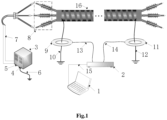
- FIG. 1 is a schematic wiring diagram of a cable leakage current testing platform according to the present invention.
- this application provides a cable leakage current testing platform, including: a host computer 1, a data collector 2, a high-frequency voltage source 3, a first port 4 of the high-frequency voltage source, a second port 5 of the high-frequency voltage source, a third ground wire 6, a high-voltage test line 7, a terminal 8, a first high-frequency current transformer 9, a first ground wire 10, a second high-frequency current transformer 11, a second ground wire 12, a first signal transmission line 13, a second signal transmission line 14, a third signal transmission line 15, and a test cable 16.
- the second port 5 of the high-frequency voltage source is connected to the terminal 8 of the test cable 16 by using the high-voltage test line 7.
- the first high-frequency current transformer 9 is sleeved on the first ground wire 10 of the test cable 16.
- the second high-frequency current transformer 11 is sleeved on the second ground wire 12 of the test cable 16.
- the first high-frequency current transformer 9 is connected to the data collector 2 by using the first signal transmission line 13.
- the second high-frequency current transformer 11 is connected to the data collector 2 by using the second signal transmission line 14.
- the data collector 2 is connected to the host computer 1 by using the third signal transmission line 15.
- the first port 4 of the high-frequency voltage source is grounded by using the third ground wire 6.
- This application further provides a method for measuring a leakage-current difference factor of a deteriorated XLPE cable based on the cable leakage current testing platform.
- the method includes:
- Obtaining the current data based on the cable leakage current testing platform specifically includes the following steps:
- Calculating the leakage-current difference factor ⁇ of the cable based on the current data specifically includes the following steps:
- Determining the insulation deterioration state of the cable based on the leakage-current difference factor ⁇ of the cable specifically includes the following steps:
- this application provides a platform and method for measuring a leakage-current difference factor of a deteriorated XLPE cable.
- the cable leakage current testing platform is first established to test leakage current of an XLPE cable in long-term operation; subsequently, the leakage-current characteristic parameter, the disturbance factor, and the deviation factor of the first high-frequency current transformer are calculated; the leakage-current characteristic parameter, the disturbance factor, and the deviation factor of the second high-frequency current transformer are calculated; and finally, the deterioration state of the XLPE cable is evaluated by means of calculating the leakage-current difference factor, thus improving reliability of power supply of the cable.
- the present invention is advantageous in that the present invention has advantages of a simple data collection operation, convenient and easy-to-understand field installation and connection steps, and an accurate and reliable calculation process. In this way, the leakage-current difference factor of the deteriorated XLPE cable may be quickly measured, to accurately and effectively evaluate insulation performance of the XLPE cable.
Landscapes
- Physics & Mathematics (AREA)
- General Physics & Mathematics (AREA)
- Engineering & Computer Science (AREA)
- Environmental & Geological Engineering (AREA)
- Testing Of Short-Circuits, Discontinuities, Leakage, Or Incorrect Line Connections (AREA)
- Testing Relating To Insulation (AREA)
Description
- The present invention relates to the field of evaluating an insulating deterioration state of an XLPE cable, and in particular, to a platform and method for measuring a leakage-current difference factor of a deteriorated XLPE cable.
- Cross linked polyethylene (XLPE) is widely used in modern urban distribution networks, and has a lot of advantages, such as high reliability of power supply, good insulation performance, good water resistance and chemical corrosion resistance. However, the XLPE has a disadvantage that cracks are easily generated under mechanical stress. At the same time, due to a complicated operating environment of a cable, the cable may deteriorate as service time goes by. Therefore, to improve reliability of power supply, it is very important to evaluate a deterioration state of the cable.
- When in a deterioration state, insulation breakdown may easily occur if the cable is not replaced in time, resulting in a large-scale power outage. As a result, industrial production and life are significantly affected. To reduce a rate of occurrence of XLPE cable failures and improve the reliability of power supply, there is an urgent need for a method that can effectively evaluate insulation performance of the XLPE cable in long-term operation in urban distribution networks. This method is a platform and method for measuring a leakage-current difference factor of a deteriorated XLPE cable. This method is simple to operate and can effectively evaluate the deterioration state of the cable by calculating detected leakage current.
- The document "Investigation of high frequency signal propagation characteristics on HV XLPE cables, O H N et. al." discloses a cable testing platform for detecting partial discharges at the dielectric of XLPE cables, and further discloses a method of testing an XLPE cable, the method comprising obtaining current data and calculating a leakage current difference factor, wherein the leakage current difference factor is the ratio of the currents between the two ends of the cable.
- An objective of the present invention is to provide a platform and method for measuring a leakage-current difference factor of a deteriorated XLPE cable, to judge an insulation deterioration state of an XLPE cable in long-term operation of urban distribution networks. This method is simple to operate and can effectively evaluate the deterioration state of the cable by calculating detected leakage current.
- Technical solutions of the present invention are set out in the appended set of claims.
- It may be learned from the foregoing technical solutions that this application provides a platform and method for measuring a leakage-current difference factor of a deteriorated XLPE cable. According to the present invention, first, the cable leakage current testing platform is first established to test leakage current of an XLPE cable in long-term operation; subsequently, the leakage-current characteristic parameter, the disturbance factor, and the deviation factor of the first high-frequency current transformer are calculated; the leakage-current characteristic parameter, the disturbance factor, and the deviation factor of the second high-frequency current transformer are calculated; and finally, the deterioration state of the XLPE cable is evaluated by means of calculating the leakage-current difference factor, thus improving reliability of power supply of the cable. The present invention is advantageous in that the present invention has advantages of a simple data collection operation, convenient and easy-to-understand field installation and connection steps, and an accurate and reliable calculation process. In this way, the leakage-current difference factor of the deteriorated XLPE cable may be quickly measured, to accurately and effectively evaluate insulation performance of the XLPE cable.
-
FIG. 1 is a schematic wiring diagram of a cable leakage current testing platform according to the present invention. - The present invention is further described below.
- According to a wiring diagram of a cable leakage current testing platform in
FIG. 1 , this application provides a cable leakage current testing platform, including:
a host computer 1, adata collector 2, a high-frequency voltage source 3, a first port 4 of the high-frequency voltage source, asecond port 5 of the high-frequency voltage source, athird ground wire 6, a high-voltage test line 7, aterminal 8, a first high-frequency current transformer 9, afirst ground wire 10, a second high-frequency current transformer 11, asecond ground wire 12, a firstsignal transmission line 13, a secondsignal transmission line 14, a thirdsignal transmission line 15, and atest cable 16. - The
second port 5 of the high-frequency voltage source is connected to theterminal 8 of thetest cable 16 by using the high-voltage test line 7. - The first high-frequency
current transformer 9 is sleeved on thefirst ground wire 10 of thetest cable 16. - The second high-frequency
current transformer 11 is sleeved on thesecond ground wire 12 of thetest cable 16. - The first high-frequency
current transformer 9 is connected to thedata collector 2 by using the firstsignal transmission line 13. - The second high-frequency
current transformer 11 is connected to thedata collector 2 by using the secondsignal transmission line 14. - The
data collector 2 is connected to the host computer 1 by using the thirdsignal transmission line 15. - The first port 4 of the high-frequency voltage source is grounded by using the
third ground wire 6. - This application further provides a method for measuring a leakage-current difference factor of a deteriorated XLPE cable based on the cable leakage current testing platform. The method includes:
- obtaining current data based on the cable leakage current testing platform;
- calculating a leakage-current difference factor λ of the cable based on the current data; and
- determining an insulation deterioration state of the cable based on the leakage-current difference factor λ of the cable.
- Obtaining the current data based on the cable leakage current testing platform specifically includes the following steps:
- collecting, by the
data collector 2, current data of thetest cable 16 by using the first high-frequency current transformer 9 and the second high-frequency current transformer 11, where there are 16 rounds of collection, duration of each round of collection is 5 min, and a time interval of every time of collecting the current data is 2s; - denoting the current data collected by the first high-frequency
current transformer 9 by αij , to represent data of j th time collected by the first high-frequencycurrent transformer 9 during i th round of collection; and - denoting the current data collected by the second high-
frequency current transformer 11 by βij , to represent data of j th time collected by the second high-frequency current transformer 11 during i th round of collection, where both i and j are real numbers, i ∈ [1,16], and j ∈ [1,150]. - Calculating the leakage-current difference factor λ of the cable based on the current data specifically includes the following steps:
- calculating a characteristic parameter δi of leakage current of the first high-frequency
current transformer 9 based on the current data, where i ∈ [1,16];

- calculating a leakage-current characteristic parameter µi of the second high-frequency
current transformer 11 based on the current data, where i ∈ [1,16];

- calculating a leakage-current disturbance factor Ki of the first high-
frequency current transformer 9 based on the current data, where i ∈ [1,16];


- calculating a leakage-current disturbance factor Li of the second high-
frequency current transformer 11 based on the current data, where i ∈ [1,16];

- calculating a leakage-current deviation factor ε of the first high-frequency
current transformer 9 based on the current data;

- calculating a leakage-current deviation factor η of the second high-frequency
current transformer 11 based on the current data;

- where ( ) represents a matrix, and • represents matrix point multiplication; and
- calculating a leakage-current difference factor λ of the cable based on the leakage-current characteristic parameter δi , the leakage-current characteristic parameter µi , the leakage-current disturbance factor Ki , the leakage-current disturbance factor Li , the leakage-current deviation factor ε, and the leakage-current deviation factor η;

- where ||ε||2 represents a 2-norm of a leakage-current deviation factor matrix ε of the first high-frequency
current transformer 9, and ∥η∥2 represents a 2-norm of a leakage-current deviation factor matrix η of the second high-frequencycurrent transformer 11. - Determining the insulation deterioration state of the cable based on the leakage-current difference factor λ of the cable specifically includes the following steps:
- if λ < θ 1, determining that the insulation deterioration state of the
test cable 16 is in a very good state; - if θ 1 ≤ λ < θ 2, determining that the insulation deterioration state of the
test cable 16 is in a good state; - if θ 2 ≤ λ < θ3 , determining that the insulation deterioration state of the
test cable 16 is in a general state; and - if λ ≥ θ 3, determining that the insulation deterioration state of the
test cable 16 is in a damaged state, where - θ 1 = 0.281, θ 2= 5.862, and θ 3 = 19.218.
- It may be aware from the foregoing technical solutions that this application provides a platform and method for measuring a leakage-current difference factor of a deteriorated XLPE cable. According to the present invention, first, the cable leakage current testing platform is first established to test leakage current of an XLPE cable in long-term operation; subsequently, the leakage-current characteristic parameter, the disturbance factor, and the deviation factor of the first high-frequency current transformer are calculated; the leakage-current characteristic parameter, the disturbance factor, and the deviation factor of the second high-frequency current transformer are calculated; and finally, the deterioration state of the XLPE cable is evaluated by means of calculating the leakage-current difference factor, thus improving reliability of power supply of the cable. The present invention is advantageous in that the present invention has advantages of a simple data collection operation, convenient and easy-to-understand field installation and connection steps, and an accurate and reliable calculation process. In this way, the leakage-current difference factor of the deteriorated XLPE cable may be quickly measured, to accurately and effectively evaluate insulation performance of the XLPE cable.
Claims (3)
- A method for measuring a leakage-current difference factor of a deteriorated cross linked polyethylene, XPLE, cable, being applied to a cable leakage current testing platform,wherein the cable leakage current testing platform, comprising:a host computer (1), a data collector (2), a high-frequency voltage source (3), a first port (4) of the high-frequency voltage source, a second port (5) of the high-frequency voltage source, a third ground wire (6), a high-voltage test line (7), a terminal (8), a first high-frequency current transformer (9), a first ground wire (10), a second high-frequency current transformer (11), a second ground wire (12), a first signal transmission line (13), a second signal transmission line (14), a third signal transmission line (15), and a test cable (16), whereinthe second port (5) of the high-frequency voltage source is connected to the terminal (8) of the test cable (16) by using the high-voltage test line (7);the first high-frequency current transformer (9) is sleeved on the first ground wire (10) of the test cable (16);the second high-frequency current transformer (11) is sleeved on the second ground wire (12) of the test cable(16);the first high-frequency current transformer (9) is connected to the data collector (2) by using the first signal transmission line (13);the second high-frequency current transformer (11) is connected to the data collector (2) by using the second signal transmission line (14);the data collector (2) is connected to the host computer (1) by using the third signal transmission line (15); andthe first port (4) of the high-frequency voltage source is grounded by using the third ground wire (6);wherein the method comprises:obtaining current data based on the cable leakage current testing platform;calculating a leakage-current difference factor λ of the cable based on the current data; anddetermining an insulation deterioration state of the cable based on the leakage-current difference factor λ of the cable,characterized in that the obtaining current data based on the cable leakage current testing platform specifically comprises the following steps:collecting, by the data collector (2), current data of the test cable (16) by using the first high-frequency current transformer (9) and the second high-frequency current transformer (11), wherein there are 16 rounds of collection, duration of each round of collection is 5 min, and a time interval of every time of collecting the current data is 2s;denoting the current data collected by the first high-frequency current transformer (9) by αij , to represent data of j th time collected by the first high-frequency current transformer (9) during i th round of collection; anddenoting the current data collected by the second high-frequency current transformer (11) by βij , to represent data of j th time collected by the second high-frequency current transformer (11) during i th round of collection, whereinboth i and j are real numbers, i ∈ [1,16], and j ∈ [1,150].
- The method according to claim 1, wherein the calculating a leakage-current difference factor λ of the cable based on the current data specifically comprises the following steps:calculating a leakage-current characteristic parameter δ i of the first high-frequency current transformer (9) based on the current data, wherein i ∈ [1,16];
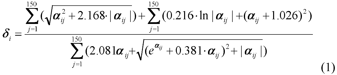 calculating a leakage-current characteristic parameter µi of the second high-frequency current transformer (11) based on the current data, wherein i ∈ [1,16];
 calculating a leakage-current disturbance factor Ki of the first high-frequency current transformer (9) based on the current data, wherein i ∈ [1,16];

 calculating a leakage-current disturbance factor Li of the second high-frequency current transformer (11) based on the current data, wherein i ∈ [1,16];
 calculating a leakage-current deviation factor ε of the first high-frequency current transformer (9) based on the current data;
 calculating a leakage-current deviation factor η of the second high-frequency current transformer (11) based on the current data;
 wherein ( ) represents a matrix, and • represents matrix point multiplication; andcalculating a leakage-current difference factor λ of the cable based on the leakage-current characteristic parameter δ i , the leakage-current characteristic parameter µ i , the leakage-current disturbance factor Ki , the leakage-current disturbance factor Li , the leakage-current deviation factor ε, and the leakage-current deviation factor η;
 wherein ||ε||2 represents a 2-norm of a leakage-current deviation factor matrix ε of the first high-frequency current transformer (9), and ∥η∥2 represents a 2-norm of a leakage-current deviation factor matrix η of the second high-frequency current transformer (11).
 - The method according to claim 1, wherein the determining an insulation deterioration state of the cable based on the leakage-current difference factor λ of the cable specifically comprises the following steps:if λ < θ 1, determining that the insulation deterioration state of the test cable (16) is in a very good state;if θ 1 ≤ λ < θ 2, determining that the insulation deterioration state of the test cable (16) is in a good state;if θ 2 ≤ λ < θ 3, determining that the insulation deterioration state of the test cable (16) is in a general state; andif λ ≥ θ 3, determining that the insulation deterioration state of the test cable (16) is in a damaged state, whereinθ 1 = 0.281, θ 2= 5.862, and θ 3 = 19.218.
Applications Claiming Priority (2)
| Application Number | Priority Date | Filing Date | Title |
|---|---|---|---|
| CN201911137674.5A CN111025097B (en) | 2019-11-19 | 2019-11-19 | Intelligent method for evaluating leakage current difference factor of XLPE cable after aging |
| PCT/CN2020/128816 WO2021098611A1 (en) | 2019-11-19 | 2020-11-13 | Platform for testing leakage current difference factor of aged xlpe cable, and method |
Publications (4)
| Publication Number | Publication Date |
|---|---|
| EP3896468A1 EP3896468A1 (en) | 2021-10-20 |
| EP3896468A4 EP3896468A4 (en) | 2022-03-02 |
| EP3896468C0 EP3896468C0 (en) | 2023-08-16 |
| EP3896468B1 true EP3896468B1 (en) | 2023-08-16 |
Family
ID=70200708
Family Applications (1)
| Application Number | Title | Priority Date | Filing Date |
|---|---|---|---|
| EP20890914.3A Active EP3896468B1 (en) | 2019-11-19 | 2020-11-13 | Platform for testing leakage current difference factor of aged xlpe cable, and method |
Country Status (3)
| Country | Link |
|---|---|
| EP (1) | EP3896468B1 (en) |
| CN (1) | CN111025097B (en) |
| WO (1) | WO2021098611A1 (en) |
Families Citing this family (14)
| Publication number | Priority date | Publication date | Assignee | Title |
|---|---|---|---|---|
| CN111025097B (en) * | 2019-11-19 | 2022-04-15 | 云南电网有限责任公司临沧供电局 | Intelligent method for evaluating leakage current difference factor of XLPE cable after aging |
| CN111650459A (en) * | 2020-06-11 | 2020-09-11 | 常州工业职业技术学院 | A wireless passive online monitor with gap arrester |
| CN114184903B (en) * | 2021-11-05 | 2022-06-28 | 西南交通大学 | 10kV XLPE cable aging state evaluation method based on electric tree state evaluation factor |
| CN114113790A (en) * | 2021-11-29 | 2022-03-01 | 云南电网有限责任公司电力科学研究院 | Multi-parameter cable insulation state diagnosis method and device based on electric charge quantity |
| CN114236332A (en) * | 2021-12-06 | 2022-03-25 | 深圳供电局有限公司 | A method and system for judging the insulation state of a power cable |
| CN114487907A (en) * | 2022-01-25 | 2022-05-13 | 中国长江三峡集团有限公司 | Beidou time service-based synchronous detection and extraction method for leakage current at two ends of alternating current cable |
| CN116106657B (en) * | 2022-11-18 | 2024-03-19 | 西南交通大学 | Method for evaluating ageing state of EPDM (ethylene-propylene-diene monomer) cable based on electron trap effect |
| CN115792535B (en) * | 2022-11-30 | 2025-10-28 | 广东电网有限责任公司 | Air-gap solid-sealed pole performance test platform and test method considering ambient humidity |
| CN116008221A (en) * | 2022-12-19 | 2023-04-25 | 国网山西省电力公司电力科学研究院 | A new aging characterization method for XLPE power cables |
| CN116520068B (en) * | 2023-07-04 | 2023-09-22 | 深圳博润缘科技有限公司 | A power data diagnosis method, device, equipment and storage medium |
| CN117554761B (en) * | 2023-11-20 | 2024-08-20 | 西南交通大学 | Evaluation method for XLPE cable insulation performance in severe cold environment |
| CN117825879B (en) * | 2023-11-20 | 2024-07-12 | 西南交通大学 | Evaluation method for insulation performance of power cable in acid-base environment |
| CN117517902B (en) * | 2023-12-06 | 2024-08-06 | 西南交通大学 | XLPE cable insulation damage state assessment method based on pulse signal transmission factor |
| CN119716297B (en) * | 2024-11-05 | 2025-07-22 | 西南交通大学 | 10KV XLPE cable sheath aging state assessment method based on electromagnetic heat mutual interference factor |
Family Cites Families (13)
| Publication number | Priority date | Publication date | Assignee | Title |
|---|---|---|---|---|
| JPS59202074A (en) * | 1983-04-30 | 1984-11-15 | Hitachi Cable Ltd | Diagnosis method for insulation deterioration of power cables |
| JPH05184028A (en) * | 1992-01-07 | 1993-07-23 | Furukawa Electric Co Ltd:The | How to lay and test power cable lines |
| KR101434079B1 (en) * | 2010-04-14 | 2014-08-25 | 미쓰비시덴키 가부시키가이샤 | Insulation deterioration diagnosis device |
| CN202066937U (en) * | 2011-04-01 | 2011-12-07 | 武汉朗德电气有限公司 | On-line cable data acquisition terminal |
| CN104459486A (en) * | 2014-11-25 | 2015-03-25 | 广东电网有限责任公司电力科学研究院 | Method for evaluating insulation of crosslinked polyethylene medium-voltage cable through polarization current |
| CN104991168A (en) * | 2015-08-11 | 2015-10-21 | 广州供电局有限公司 | Cable running state assessment method and system |
| CN107621595A (en) * | 2017-03-28 | 2018-01-23 | 国网四川省电力公司电力科学研究院 | A kind of Condition assessment of insulation device and method of power cable |
| CN107015119B (en) * | 2017-05-12 | 2019-05-07 | 中广核核电运营有限公司 | A kind of signal cable line fault diagnosis device and method |
| CN108469577A (en) * | 2018-05-24 | 2018-08-31 | 广东电网有限责任公司 | A kind of device by leakage current measurement cable aging |
| CN108983048A (en) * | 2018-06-01 | 2018-12-11 | 广东电网有限责任公司 | Direct current cables terminating insulation performance on-line monitoring system |
| CN110008278B (en) * | 2019-02-25 | 2021-03-02 | 国网浙江省电力有限公司电力科学研究院 | Distribution network cable fault discrimination method and system by using grounding current signal |
| CN111025096B (en) * | 2019-11-19 | 2021-08-10 | 云南电网有限责任公司临沧供电局 | XLPE cable aging state evaluation method based on leakage current characteristic factor |
| CN111025097B (en) * | 2019-11-19 | 2022-04-15 | 云南电网有限责任公司临沧供电局 | Intelligent method for evaluating leakage current difference factor of XLPE cable after aging |
-
2019
- 2019-11-19 CN CN201911137674.5A patent/CN111025097B/en active Active
-
2020
- 2020-11-13 EP EP20890914.3A patent/EP3896468B1/en active Active
- 2020-11-13 WO PCT/CN2020/128816 patent/WO2021098611A1/en not_active Ceased
Also Published As
| Publication number | Publication date |
|---|---|
| CN111025097B (en) | 2022-04-15 |
| EP3896468C0 (en) | 2023-08-16 |
| CN111025097A (en) | 2020-04-17 |
| EP3896468A1 (en) | 2021-10-20 |
| EP3896468A4 (en) | 2022-03-02 |
| WO2021098611A1 (en) | 2021-05-27 |
Similar Documents
| Publication | Publication Date | Title |
|---|---|---|
| EP3896468A1 (en) | Platform for testing leakage current difference factor of aged xlpe cable, and method | |
| KR100541996B1 (en) | A dignosis method of insulation of electric apparatus | |
| CN104678246B (en) | A kind of grounding net of transformer substation etch state appraisal procedure and its system | |
| EP1133701B1 (en) | Method for diagnosing insulation degradation in underground cable | |
| CN105699843A (en) | Electric cable running state diagnosis method and system | |
| KR102148618B1 (en) | Device and system for diagnosing power cable, and method for diagnosing power calbe using the same | |
| CN109342882A (en) | On-line monitoring method of cable fault based on multi-source eigenvalue analysis | |
| CN113884837B (en) | Cable partial discharge online monitoring and analyzing system and analyzing method | |
| CN105203866B (en) | A kind of High Voltage XLPE Power Cable method for diagnosing faults based on method of loci | |
| CN110763957A (en) | A new method for online monitoring of medium voltage cable insulation faults | |
| CN108828398B (en) | Single-core cable partial discharge positioning method based on structural similarity algorithm | |
| CN116840614A (en) | Cable line defect sensing and early warning method based on harmonic fluctuation characteristics | |
| CN109959845A (en) | A method and system for locating local defects in cable lines | |
| CN112180288A (en) | Method for analyzing and processing ground fault of insulation damage of outer sheath of 220kV cable | |
| Anthony et al. | Development of condition assessment criteria for medium voltage underground cable water ingress joint using combined diagnostic testing | |
| CN118244058B (en) | Cable fault detection system | |
| CN113640635A (en) | Power cable insulation state online monitoring method | |
| US20050212524A1 (en) | Electric power line on-line diagnostic method | |
| Zhu et al. | Improvement of cable defect identification for power distribution networks | |
| CN112557851A (en) | Power cable partial discharge on-line positioning system and method based on transfer function | |
| CN116148571A (en) | A cable condition monitoring method based on magnetic field detection | |
| CN118112370A (en) | A method, device and equipment for locating faults in hybrid overhead lines of a distribution network | |
| Hartlein et al. | Diagnostic testing of underground cable systems (Cable Diagnostic Focused Initiative) | |
| CN105676079A (en) | Cable partial discharge source positioning method based on online decision rule | |
| CN114414959B (en) | Cable insulation detection device and method based on Gaussian pulse bidirectional propagation coefficient |
Legal Events
| Date | Code | Title | Description |
|---|---|---|---|
| STAA | Information on the status of an ep patent application or granted ep patent |
Free format text: STATUS: THE INTERNATIONAL PUBLICATION HAS BEEN MADE |
|
| PUAI | Public reference made under article 153(3) epc to a published international application that has entered the european phase |
Free format text: ORIGINAL CODE: 0009012 |
|
| STAA | Information on the status of an ep patent application or granted ep patent |
Free format text: STATUS: REQUEST FOR EXAMINATION WAS MADE |
|
| 17P | Request for examination filed |
Effective date: 20210712 |
|
| AK | Designated contracting states |
Kind code of ref document: A1 Designated state(s): AL AT BE BG CH CY CZ DE DK EE ES FI FR GB GR HR HU IE IS IT LI LT LU LV MC MK MT NL NO PL PT RO RS SE SI SK SM TR |
|
| A4 | Supplementary search report drawn up and despatched |
Effective date: 20220128 |
|
| RIC1 | Information provided on ipc code assigned before grant |
Ipc: G01R 31/58 20200101ALI20220124BHEP Ipc: G01R 31/52 20200101ALI20220124BHEP Ipc: G01R 31/00 20060101ALI20220124BHEP Ipc: G01R 31/12 20200101AFI20220124BHEP |
|
| STAA | Information on the status of an ep patent application or granted ep patent |
Free format text: STATUS: EXAMINATION IS IN PROGRESS |
|
| 17Q | First examination report despatched |
Effective date: 20221011 |
|
| DAV | Request for validation of the european patent (deleted) | ||
| DAX | Request for extension of the european patent (deleted) | ||
| GRAP | Despatch of communication of intention to grant a patent |
Free format text: ORIGINAL CODE: EPIDOSNIGR1 |
|
| STAA | Information on the status of an ep patent application or granted ep patent |
Free format text: STATUS: GRANT OF PATENT IS INTENDED |
|
| INTG | Intention to grant announced |
Effective date: 20230411 |
|
| GRAS | Grant fee paid |
Free format text: ORIGINAL CODE: EPIDOSNIGR3 |
|
| GRAA | (expected) grant |
Free format text: ORIGINAL CODE: 0009210 |
|
| STAA | Information on the status of an ep patent application or granted ep patent |
Free format text: STATUS: THE PATENT HAS BEEN GRANTED |
|
| AK | Designated contracting states |
Kind code of ref document: B1 Designated state(s): AL AT BE BG CH CY CZ DE DK EE ES FI FR GB GR HR HU IE IS IT LI LT LU LV MC MK MT NL NO PL PT RO RS SE SI SK SM TR |
|
| REG | Reference to a national code |
Ref country code: CH Ref legal event code: EP |
|
| REG | Reference to a national code |
Ref country code: DE Ref legal event code: R096 Ref document number: 602020015991 Country of ref document: DE |
|
| REG | Reference to a national code |
Ref country code: IE Ref legal event code: FG4D |
|
| U01 | Request for unitary effect filed |
Effective date: 20230821 |
|
| U07 | Unitary effect registered |
Designated state(s): AT BE BG DE DK EE FI FR IT LT LU LV MT NL PT SE SI Effective date: 20230825 |
|
| U20 | Renewal fee for the european patent with unitary effect paid |
Year of fee payment: 4 Effective date: 20231107 |
|
| PG25 | Lapsed in a contracting state [announced via postgrant information from national office to epo] |
Ref country code: GR Free format text: LAPSE BECAUSE OF FAILURE TO SUBMIT A TRANSLATION OF THE DESCRIPTION OR TO PAY THE FEE WITHIN THE PRESCRIBED TIME-LIMIT Effective date: 20231117 |
|
| PG25 | Lapsed in a contracting state [announced via postgrant information from national office to epo] |
Ref country code: IS Free format text: LAPSE BECAUSE OF FAILURE TO SUBMIT A TRANSLATION OF THE DESCRIPTION OR TO PAY THE FEE WITHIN THE PRESCRIBED TIME-LIMIT Effective date: 20231216 |
|
| PG25 | Lapsed in a contracting state [announced via postgrant information from national office to epo] |
Ref country code: RS Free format text: LAPSE BECAUSE OF FAILURE TO SUBMIT A TRANSLATION OF THE DESCRIPTION OR TO PAY THE FEE WITHIN THE PRESCRIBED TIME-LIMIT Effective date: 20230816 Ref country code: NO Free format text: LAPSE BECAUSE OF FAILURE TO SUBMIT A TRANSLATION OF THE DESCRIPTION OR TO PAY THE FEE WITHIN THE PRESCRIBED TIME-LIMIT Effective date: 20231116 Ref country code: IS Free format text: LAPSE BECAUSE OF FAILURE TO SUBMIT A TRANSLATION OF THE DESCRIPTION OR TO PAY THE FEE WITHIN THE PRESCRIBED TIME-LIMIT Effective date: 20231216 Ref country code: HR Free format text: LAPSE BECAUSE OF FAILURE TO SUBMIT A TRANSLATION OF THE DESCRIPTION OR TO PAY THE FEE WITHIN THE PRESCRIBED TIME-LIMIT Effective date: 20230816 Ref country code: GR Free format text: LAPSE BECAUSE OF FAILURE TO SUBMIT A TRANSLATION OF THE DESCRIPTION OR TO PAY THE FEE WITHIN THE PRESCRIBED TIME-LIMIT Effective date: 20231117 |
|
| PG25 | Lapsed in a contracting state [announced via postgrant information from national office to epo] |
Ref country code: PL Free format text: LAPSE BECAUSE OF FAILURE TO SUBMIT A TRANSLATION OF THE DESCRIPTION OR TO PAY THE FEE WITHIN THE PRESCRIBED TIME-LIMIT Effective date: 20230816 |
|
| PG25 | Lapsed in a contracting state [announced via postgrant information from national office to epo] |
Ref country code: ES Free format text: LAPSE BECAUSE OF FAILURE TO SUBMIT A TRANSLATION OF THE DESCRIPTION OR TO PAY THE FEE WITHIN THE PRESCRIBED TIME-LIMIT Effective date: 20230816 |
|
| PG25 | Lapsed in a contracting state [announced via postgrant information from national office to epo] |
Ref country code: SM Free format text: LAPSE BECAUSE OF FAILURE TO SUBMIT A TRANSLATION OF THE DESCRIPTION OR TO PAY THE FEE WITHIN THE PRESCRIBED TIME-LIMIT Effective date: 20230816 Ref country code: RO Free format text: LAPSE BECAUSE OF FAILURE TO SUBMIT A TRANSLATION OF THE DESCRIPTION OR TO PAY THE FEE WITHIN THE PRESCRIBED TIME-LIMIT Effective date: 20230816 Ref country code: ES Free format text: LAPSE BECAUSE OF FAILURE TO SUBMIT A TRANSLATION OF THE DESCRIPTION OR TO PAY THE FEE WITHIN THE PRESCRIBED TIME-LIMIT Effective date: 20230816 Ref country code: CZ Free format text: LAPSE BECAUSE OF FAILURE TO SUBMIT A TRANSLATION OF THE DESCRIPTION OR TO PAY THE FEE WITHIN THE PRESCRIBED TIME-LIMIT Effective date: 20230816 Ref country code: SK Free format text: LAPSE BECAUSE OF FAILURE TO SUBMIT A TRANSLATION OF THE DESCRIPTION OR TO PAY THE FEE WITHIN THE PRESCRIBED TIME-LIMIT Effective date: 20230816 |
|
| PLBE | No opposition filed within time limit |
Free format text: ORIGINAL CODE: 0009261 |
|
| STAA | Information on the status of an ep patent application or granted ep patent |
Free format text: STATUS: NO OPPOSITION FILED WITHIN TIME LIMIT |
|
| REG | Reference to a national code |
Ref country code: CH Ref legal event code: PL |
|
| PG25 | Lapsed in a contracting state [announced via postgrant information from national office to epo] |
Ref country code: MC Free format text: LAPSE BECAUSE OF FAILURE TO SUBMIT A TRANSLATION OF THE DESCRIPTION OR TO PAY THE FEE WITHIN THE PRESCRIBED TIME-LIMIT Effective date: 20230816 |
|
| PG25 | Lapsed in a contracting state [announced via postgrant information from national office to epo] |
Ref country code: CH Free format text: LAPSE BECAUSE OF NON-PAYMENT OF DUE FEES Effective date: 20231130 |
|
| 26N | No opposition filed |
Effective date: 20240517 |
|
| PG25 | Lapsed in a contracting state [announced via postgrant information from national office to epo] |
Ref country code: MC Free format text: LAPSE BECAUSE OF FAILURE TO SUBMIT A TRANSLATION OF THE DESCRIPTION OR TO PAY THE FEE WITHIN THE PRESCRIBED TIME-LIMIT Effective date: 20230816 Ref country code: CH Free format text: LAPSE BECAUSE OF NON-PAYMENT OF DUE FEES Effective date: 20231130 |
|
| REG | Reference to a national code |
Ref country code: IE Ref legal event code: MM4A |
|
| PG25 | Lapsed in a contracting state [announced via postgrant information from national office to epo] |
Ref country code: IE Free format text: LAPSE BECAUSE OF NON-PAYMENT OF DUE FEES Effective date: 20231113 |
|
| PG25 | Lapsed in a contracting state [announced via postgrant information from national office to epo] |
Ref country code: IE Free format text: LAPSE BECAUSE OF NON-PAYMENT OF DUE FEES Effective date: 20231113 |
|
| U20 | Renewal fee for the european patent with unitary effect paid |
Year of fee payment: 5 Effective date: 20241010 |
|
| GBPC | Gb: european patent ceased through non-payment of renewal fee |
Effective date: 20241113 |
|
| PG25 | Lapsed in a contracting state [announced via postgrant information from national office to epo] |
Ref country code: CY Free format text: LAPSE BECAUSE OF FAILURE TO SUBMIT A TRANSLATION OF THE DESCRIPTION OR TO PAY THE FEE WITHIN THE PRESCRIBED TIME-LIMIT; INVALID AB INITIO Effective date: 20201113 |
|
| PG25 | Lapsed in a contracting state [announced via postgrant information from national office to epo] |
Ref country code: HU Free format text: LAPSE BECAUSE OF FAILURE TO SUBMIT A TRANSLATION OF THE DESCRIPTION OR TO PAY THE FEE WITHIN THE PRESCRIBED TIME-LIMIT; INVALID AB INITIO Effective date: 20201113 |
|
| U20 | Renewal fee for the european patent with unitary effect paid |
Year of fee payment: 6 Effective date: 20250909 |
|
| PG25 | Lapsed in a contracting state [announced via postgrant information from national office to epo] |
Ref country code: GB Free format text: LAPSE BECAUSE OF NON-PAYMENT OF DUE FEES Effective date: 20241113 |
|
| PG25 | Lapsed in a contracting state [announced via postgrant information from national office to epo] |
Ref country code: TR Free format text: LAPSE BECAUSE OF FAILURE TO SUBMIT A TRANSLATION OF THE DESCRIPTION OR TO PAY THE FEE WITHIN THE PRESCRIBED TIME-LIMIT Effective date: 20230816 |