EP3896341B1 - Gas turbine combustor - Google Patents
Gas turbine combustor Download PDFInfo
- Publication number
- EP3896341B1 EP3896341B1 EP21167537.6A EP21167537A EP3896341B1 EP 3896341 B1 EP3896341 B1 EP 3896341B1 EP 21167537 A EP21167537 A EP 21167537A EP 3896341 B1 EP3896341 B1 EP 3896341B1
- Authority
- EP
- European Patent Office
- Prior art keywords
- fuel
- air
- guide member
- supply tube
- fuel supply
- Prior art date
- Legal status (The legal status is an assumption and is not a legal conclusion. Google has not performed a legal analysis and makes no representation as to the accuracy of the status listed.)
- Active
Links
Images




Classifications
-
- F—MECHANICAL ENGINEERING; LIGHTING; HEATING; WEAPONS; BLASTING
- F23—COMBUSTION APPARATUS; COMBUSTION PROCESSES
- F23R—GENERATING COMBUSTION PRODUCTS OF HIGH PRESSURE OR HIGH VELOCITY, e.g. GAS-TURBINE COMBUSTION CHAMBERS
- F23R3/00—Continuous combustion chambers using liquid or gaseous fuel
- F23R3/02—Continuous combustion chambers using liquid or gaseous fuel characterised by the air-flow or gas-flow configuration
- F23R3/04—Air inlet arrangements
- F23R3/10—Air inlet arrangements for primary air
- F23R3/12—Air inlet arrangements for primary air inducing a vortex
- F23R3/14—Air inlet arrangements for primary air inducing a vortex by using swirl vanes
-
- F—MECHANICAL ENGINEERING; LIGHTING; HEATING; WEAPONS; BLASTING
- F23—COMBUSTION APPARATUS; COMBUSTION PROCESSES
- F23R—GENERATING COMBUSTION PRODUCTS OF HIGH PRESSURE OR HIGH VELOCITY, e.g. GAS-TURBINE COMBUSTION CHAMBERS
- F23R3/00—Continuous combustion chambers using liquid or gaseous fuel
- F23R3/02—Continuous combustion chambers using liquid or gaseous fuel characterised by the air-flow or gas-flow configuration
- F23R3/16—Continuous combustion chambers using liquid or gaseous fuel characterised by the air-flow or gas-flow configuration with devices inside the flame tube or the combustion chamber to influence the air or gas flow
-
- F—MECHANICAL ENGINEERING; LIGHTING; HEATING; WEAPONS; BLASTING
- F23—COMBUSTION APPARATUS; COMBUSTION PROCESSES
- F23R—GENERATING COMBUSTION PRODUCTS OF HIGH PRESSURE OR HIGH VELOCITY, e.g. GAS-TURBINE COMBUSTION CHAMBERS
- F23R3/00—Continuous combustion chambers using liquid or gaseous fuel
- F23R3/28—Continuous combustion chambers using liquid or gaseous fuel characterised by the fuel supply
- F23R3/283—Attaching or cooling of fuel injecting means including supports for fuel injectors, stems, or lances
-
- F—MECHANICAL ENGINEERING; LIGHTING; HEATING; WEAPONS; BLASTING
- F23—COMBUSTION APPARATUS; COMBUSTION PROCESSES
- F23R—GENERATING COMBUSTION PRODUCTS OF HIGH PRESSURE OR HIGH VELOCITY, e.g. GAS-TURBINE COMBUSTION CHAMBERS
- F23R3/00—Continuous combustion chambers using liquid or gaseous fuel
- F23R3/28—Continuous combustion chambers using liquid or gaseous fuel characterised by the fuel supply
- F23R3/286—Continuous combustion chambers using liquid or gaseous fuel characterised by the fuel supply having fuel-air premixing devices
-
- F—MECHANICAL ENGINEERING; LIGHTING; HEATING; WEAPONS; BLASTING
- F23—COMBUSTION APPARATUS; COMBUSTION PROCESSES
- F23R—GENERATING COMBUSTION PRODUCTS OF HIGH PRESSURE OR HIGH VELOCITY, e.g. GAS-TURBINE COMBUSTION CHAMBERS
- F23R3/00—Continuous combustion chambers using liquid or gaseous fuel
- F23R3/28—Continuous combustion chambers using liquid or gaseous fuel characterised by the fuel supply
- F23R3/38—Continuous combustion chambers using liquid or gaseous fuel characterised by the fuel supply comprising rotary fuel injection means
-
- F—MECHANICAL ENGINEERING; LIGHTING; HEATING; WEAPONS; BLASTING
- F23—COMBUSTION APPARATUS; COMBUSTION PROCESSES
- F23R—GENERATING COMBUSTION PRODUCTS OF HIGH PRESSURE OR HIGH VELOCITY, e.g. GAS-TURBINE COMBUSTION CHAMBERS
- F23R2900/00—Special features of, or arrangements for continuous combustion chambers; Combustion processes therefor
- F23R2900/00002—Gas turbine combustors adapted for fuels having low heating value [LHV]
-
- Y—GENERAL TAGGING OF NEW TECHNOLOGICAL DEVELOPMENTS; GENERAL TAGGING OF CROSS-SECTIONAL TECHNOLOGIES SPANNING OVER SEVERAL SECTIONS OF THE IPC; TECHNICAL SUBJECTS COVERED BY FORMER USPC CROSS-REFERENCE ART COLLECTIONS [XRACs] AND DIGESTS
- Y02—TECHNOLOGIES OR APPLICATIONS FOR MITIGATION OR ADAPTATION AGAINST CLIMATE CHANGE
- Y02T—CLIMATE CHANGE MITIGATION TECHNOLOGIES RELATED TO TRANSPORTATION
- Y02T50/00—Aeronautics or air transport
- Y02T50/60—Efficient propulsion technologies, e.g. for aircraft
- Y02T50/678—Aviation using fuels of non-fossil origin
Definitions
- the present invention relates to a gas turbine combustor applicable to a gas turbine engine.
- a combustion method adopting a premixed combustion method which effectively reduces a NOx generation amount, e.g., a combined combustion method using a lean premixed combustion method and a diffusion combustion method in combination ( JP Laid-open Patent Publication No. H08-210641 ).
- JP Patent No. 6285081 JP Patent No. 6285081 .
- JP Patent No. 6285081 a plurality of fuel injection annular portions and a plurality of combustion air annular portions are concentrically arranged alternately, and a fuel supply header and the fuel injection annular portions are connected by a plurality of branched fuel supply pipes.
- the structure of the combustor is complicated.
- a space for providing the plurality of branched fuel supply pipes is secured between the fuel supply header and the fuel injection annular portions located on the downstream side thereof, and accordingly, the entire combustor is elongated in the axial direction.
- a gas turbine combustor according to the prior art is described by EP1391657 .
- An object of the present invention is to provide a gas turbine combustor that enables simplification of the structure and reduction in the axial length of the entire device.
- a gas turbine combustor of the present invention is described in claim 1.
- the fuel injector includes a fuel supply tube penetrating through the housing chamber and configured to supply fuel to the combustion chamber, and a guide member provided on an outer side of a downstream portion of the fuel supply tube.
- the guide member is configured to allow air to pass therethrough.
- the fuel supply tube includes, in the downstream portion thereof, a plurality of fuel injection holes configured to inject fuel to the air passing through the guide member, so as to mix the fuel with the air.
- the guide member is configured to supply the air and the fuel therefrom into the combustion chamber.
- the fuel injectors are designed as a module containing multiple flames, fuel injectors of the same design (cylindrical shape or polygonal shape) can be arrayed to form a tessellation, the size and shape of which can be flexibly adjusted according to different power demands and design constraints.
- the fuel supply tube penetrates through the housing chamber and supplies the fuel to the combustion chamber.
- the fuel injection holes are provided for injecting the fuel to the air passing through the guide member so as to mix the fuel with the air, and the air and the fuel are supplied from the guide member to the combustion chamber.
- the number of parts can be decreased and the structure can be simplified.
- the axial length of the entire device can be shortened as compared to the conventional structure.
- an air introduction passage formed between the combustion liner and a housing covering the combustion liner, and configured to introduce the air into the housing chamber may be provided.
- the structure can be made in a reverse-flow type in which the flowing directions of the air and the fuel are opposite to each other.
- the entire device can be further made compact in the axial direction.
- a distribution plate for the air is provided at a part where the housing chamber and the air introduction passage communicate with each other.
- the air introduced from the air introduction passage passes through the distribution plate, whereby the air is straightened into uniform flow on the downstream side of the distribution plate.
- the guide member may have a cylindrical shape or a polygonal shape as viewed in an axial direction of the fuel supply tube, and may be formed with a guide groove that the fuel injection hole faces.
- the air introduced into the guide member increases in the flow speed when passing through the guide groove, and as a result, the fuel is smoothly sucked into the air, so that mixture with the air is promoted.
- the fuel injection hole may open in a direction of 0 to 30° with respect to a radial direction of the fuel supply tube
- the guide groove of the guide member may open in a direction of 0 to 30° with respect to the axial direction of the fuel supply tube
- the fuel injector may be configured such that an air flow-out direction from the guide groove has an angle of 60° to 90° with respect to the fuel injection holes.
- the opening angle of the fuel injection holes is greater than 30° with respect to the radial direction of the fuel supply tube, manufacturing complexity for the fuel injection hole is reduced.
- the outlet opening angle of the guide member is greater than 30° with respect to the axial direction of the fuel supply tube, fuel and air might not be favorably mixed.
- the air passage direction of the guide groove is smaller than 60° or greater than 90° with respect to the fuel injection hole, mixture of fuel and air might be hampered.
- the fuel injection holes open in a direction of 0 to 30° with respect to the radial direction of the fuel supply tube, so that the manufacturing cost can be reduced.
- the guide groove of the guide member opens in a direction of 0 to 30° with respect to the axial direction of the fuel supply tube, whereby the air and the fuel are favorably mixed to be supplied to the combustion chamber.
- the air passage direction from the guide groove has an angle of 60° to 90° with respect to the fuel injection holes, so that turbulence of fuel is promoted and thus the air and the fuel can be uniformly mixed.
- a fixed swirl vane may be provided on an inner side of the guide member, for swirling the air passing between the guide member and the fuel supply tube around the guide member.
- a fixed swirl vane may be provided on an inner side of the guide member, for swirling the air passing between the guide member and the fuel supply tube around the guide member.
- mixture of the air and the fuel is promoted by the swirl vane.
- a combustor according to the first embodiment of the present invention will be described with reference to Figs. 1 to 7 .
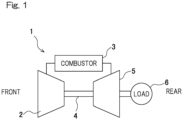
- a gas turbine engine 1 includes a compressor 2, a combustor 3, and a turbine 5 connected to the compressor 2 via a rotary shaft 4.
- the gas turbine engine is simply referred to as gas turbine 1.
- the compressor 2 In the gas turbine 1, introduced air is compressed by the compressor 2 and guided to the combustor 3, fuel is injected into the combustor 3 so as to be combusted together with the air, and then the turbine 5 is driven by the obtained high-temperature high-pressure combustion gas. By the driving of the turbine 5, the compressor 2 is driven. By output of the gas turbine 1, a load 6 such as an electric generator or a rotor of an aircraft is driven. As fuel to be injected into the combustor 3, for example, hydrogen gas is used.
- the compressor 2 side in the axial direction of the gas turbine 1 is referred to as "front side”
- the turbine 5 side in the axial direction of the gas turbine 1 is referred to as "rear side”.
- a plurality of the combustors 3 are arranged around a rotation axis of the gas turbine 1, and as shown in Fig. 2 , are supported by a main housing MH of the gas turbine 1 ( Fig. 1 ).
- Each combustor 3 includes a housing 7, a combustion liner 8, a fuel injector 9, and a housing chamber 10 housing the fuel injector 9.
- These components of the combustor 3 may be made of, for example, metal having a light weight and heat resistance.
- the housing 7 is a substantially cylindrical member forming an outer barrel of the combustor 3, and houses the combustion liner 8.
- a spark plug P is attached near the middle portion in the longitudinal direction of the housing 7, and a tip end of the spark plug P is inserted into a combustion chamber 8a in the combustion liner 8.
- the housing 7 has a front end covered by an end cover 14, which is fixed by a plurality of bolts 15.
- the cylindrical housing chamber 10 is provided concentrically with the housing 7.
- the housing chamber 10 is located upstream of the combustion chamber 8a.
- the combustion liner 8 is provided so as to cylindrically extend from the housing chamber 10, and the combustion liner 8 and the housing chamber 10 are provided concentrically with the housing 7.
- an air introduction passage 16 is formed between the combustion liner 8 forming the combustion chamber 8a therein and the housing 7 covering the combustion liner 8.
- the air introduction passage 16 introduces air A compressed by the compressor 2 ( Fig. 1 ), into the housing chamber 10.
- the combustor 3 is formed in a reverse-flow type in which the flowing directions of the air A and the fuel F are opposite to each other.
- the fuel F and the air A injected into the combustion chamber 8a are ignited by the spark plug P, whereby flame is formed in the combustion chamber 8a.
- the housing chamber 10 is located upstream of the combustion chamber 8a and houses a plurality of the fuel injectors 9. These fuel injectors 9 are provided at a top portion (most upstream portion) of the combustion liner 8, and inject the fuel F into the combustion chamber 8a.
- Each fuel injector 9 includes a bottomed-tubular fuel supply tube 11 which penetrates through the housing chamber 10 and supplies the fuel F to the combustion chamber 8a, and a tubular guide member 12 provided on the outer side of a downstream end of the fuel supply tube 11.
- the guide member 12 has a cylindrical shape as viewed in the direction of an axis C2 of the fuel supply tube 11.
- the fuel supply tube 11 and the guide member 12 are concentric with each other, and connected by a connection wall 13.
- a partition wall 17 is provided for partitioning the housing chamber 10 and the combustion chamber 8a from each other, and a plurality of the guide members 12 are attached to the partition wall 17 so as to penetrate therethrough.
- the fuel supply tube 11 and the guide member 12, and the connection wall 13 are welded to each other, and the guide member 12 and the partition wall 17 are also welded to each other.
- a plurality of fuel injection holes 18 are provided in a circumferential wall of the fuel supply tube 11, on a slightly downstream side of the connection wall 13.
- the plurality of the fuel injection holes 18 are arranged at equal intervals in the circumferential wall of the fuel supply tube 11.
- the air A is supplied from the upstream side to the fuel F which has been injected from the fuel injection holes 18.
- a plurality of guide grooves 20 for allowing air to pass therethrough are formed in the connection wall 13.
- the plurality of guide grooves 20 are arranged at equal intervals in the circumferential direction.
- Each fuel injection hole 18 faces the downstream side of the guide groove 20.
- the guide member 12 is formed by a cylindrical guide tube 12A, and the guide groove 20 that the fuel injection hole 18 faces is formed on the inner side of the guide tube 12A.
- each fuel injection hole 18 opens in a direction of 0° with respect to a radial direction R1 of the fuel supply tube 11, i.e., opens along the radial direction R1.
- the opening angle of the fuel injection hole 18 is not limited to 0°.
- the guide member 12 is provided so that the air flow-out direction thereof has an angle of 90° with respect to the fuel injection holes 18.
- upstream portions of the fuel supply tubes 11 are supported by the end cover 14, and downstream portions thereof are supported by the partition wall 17 via the guide members 12 and the connection walls 13.
- the fuel supply tubes 11 are arranged such that the directions of the axes C2 thereof are parallel to the direction of an axis C1 of the housing chamber 10 and the fuel supply tubes 11 are distant from each other by a predetermined interval.
- the fuel F is supplied from the outside to each set of predetermined three fuel supply tubes 11 adjacent to each other. Upstream portions of the fuel supply tubes 11 in each set communicate with each other via a communication path 21, and the communication path 21 communicates with a fuel supply port 22 protruding from the end cover 14. The fuel F is supplied from each fuel supply port 22.
- a distribution plate 23 for air is provided at a part where the housing chamber 10 and the air introduction passage 16 communicate with each other.
- the distribution plate 23 is formed in a cylindrical shape concentric with the direction of the axis C1 of the combustion liner 8.
- the distribution plate 23 has a circumferential wall formed with a plurality of through holes 23a penetrating the circumferential wall in the radial direction.
- the through holes 23a are arranged at predetermined intervals in the circumferential direction and the axial direction.
- the air A introduced from the air introduction passage 16 passes through the plurality of through holes 23a ( Fig. 7 ) of the distribution plate 23, whereby the air A is formed into uniformly distributed flow on the downstream side of the distribution plate 23.
- the plurality of fuel supply tubes 11 shown in Fig. 2 are arranged spaced from each other by a predetermined interval, and the plurality of fuel injection holes 18 are arranged in the circumferential direction at a downstream portion of each fuel supply tube 11. Therefore, the fuel F is injected from the fuel injectors 9 uniformly over the entire area of the combustion chamber 8a.
- minute flames are held at multiple points. Accordingly, occurrence of local high-temperature combustion is prevented, and generation of NOx can be suppressed.
- the air A is supplied from the upstream side to the fuel F injected from the fuel injection holes 18, the flames do not enter the inner sides of the fuel injectors 9, whereby a backfire phenomenon is suppressed.
- Each fuel supply tube 11 penetrates through the housing chamber 10 and supplies the fuel F to the combustion chamber 8a.
- the fuel injection holes 18 are provided for injecting the fuel F to the inner side of the guide member 12 so as to mix the fuel F with the air A, and the air A and the fuel F are supplied from the guide member 12 to the combustion chamber 8a.
- the air A and the fuel F are supplied from the guide member 12 to the combustion chamber 8a. Therefore, as compared to the conventional structure ( JP Patent No.
- the air introduction passage 16 for introducing the air A into the housing chamber 10 is formed between the combustion liner 8 and the housing 7. Therefore, the structure can be made in a reverse-flow type in which the flowing directions of the air A and the fuel F are opposite to each other. Thus, the entire device can be further made compact in the axial direction.
- the guide groove 20 that the fuel injection holes 18 face is formed on the inner side of the guide member 12. Therefore, the air A introduced to the inner side of the guide member 12 increases in the flow speed when passing through the guide groove 20, and as a result, the fuel F is smoothly sucked into the air A, so that mixture with the air A is promoted.
- the fuel injection holes 18 open in a direction of 0° with respect to the radial direction R1 of the fuel supply tube 11. Therefore, the manufacturing cost can be reduced.
- the guide member 12 opens in a direction of 0° with respect to the axis C2 of the fuel supply tube 11. Therefore, the passage in the guide member 12, i.e., the air flow-out direction has an angle of 90° with respect to the fuel injection holes 18, so that the air A transversely crosses the fuel F, thus promoting mixture of the air A and the fuel F.
- the fuel injection hole 18 may be provided on the upstream side of the guide groove 20.
- the fuel injection holes 18 open so as to be inclined toward the downstream side by a predetermined angle ⁇ with respect to the radial direction R1 of the fuel supply tube 11.
- the angle ⁇ is 0 to 30° (+30°).
- the inclination angle of the fuel injection holes 18 in a case where the fuel injection holes 18 are inclined toward the downstream side in the axial direction as approaching toward the outer side in the radial direction is defined as a "positive" inclination angle.
- the guide groove 20 of the guide member 12 opens in a direction of a predetermined angle ⁇ with respect to the axis C2 of the fuel supply tube 11.
- the angle ⁇ is a to 30° (+30°).
- the inclination angle in a case where the guide groove 20 is inclined outward in the radial direction as approaching the upstream side is defined as a "positive" inclination angle.
- the passage direction of the guide groove 20 of the guide member 12 has a predetermined angle ⁇ with respect to the fuel injection holes 18.
- the angle ⁇ is 60° to 90°.
- angles ⁇ , ⁇ , ⁇ are angles arbitrarily determined in accordance with designing or the like, and for example, determined by finding appropriate angles through one or both of a test and a simulation, or the like.
- the manufacturing cost can be reduced. Since the guide groove 20 of the guide member 12 opens in a direction of 0 to 30° with respect to the axis C2 of the fuel supply tube 11, the air A and the fuel F are favorably mixed to be supplied to the combustion chamber 8a. Since the passage direction of the guide member 12 has an angle of 60° to 90° with respect to the fuel injection holes 18, the fuel F is smoothly injected, whereby the air A and the fuel F can be uniformly mixed.
- the angle ⁇ is 0 to 30°, the angle ⁇ is 0 to 30°, and the angle ⁇ is 60° to 90°.
- Fig. 9 and Fig. 10 on the inner side of the guide member 12, fixed swirl vanes 24 are provided for swirl the air A passing between the connection wall 13 and the fuel supply tube 11 around in the guide tube 12A.
- the swirl vanes 24 are formed by a plurality of inclined vanes 26 ( Fig. 11 ) fixed between the inner and outer rings, and are generally called a swirler.
- Fig. 11 sectional view along line XI-XI in Fig. 9
- the vanes 26 are inclined by an inclination angle ⁇ with respect to the axis C2 of the guide member 12 ( Fig. 10 ).
- the inclination angle ⁇ is 15° to 45°, and preferably, 20° to 40°.
- Fig. 12 to Fig. 15 show the fuel injector 9 of the present embodiment.
- a guide member 12B in this example has a guide wall 27 having a hexagonal shape as seen in the direction of the axis C2 of the fuel supply tube 11, and an outer peripheral protrusion 28 joined to the outer peripheral surface of the guide wall 27.
- the outer peripheral protrusion 28 is formed in a hexagonal frame shape in a front view.
- outer edges of a plurality of outer peripheral protrusions 28 adjacent to each other in the radial direction are joined to each other without gaps, whereby a plurality of fuel injectors 9 are arranged in a honeycomb shape.
- the outer peripheral protrusions 28 located on the radially outermost side in Fig. 14 are joined to the partition wall 17. The above joining for each part is made by welding, for example.
- the fuel supply tube 11 has a cylindrical fuel supply tube body 11a and a bottomed hexagonal cylindrical box 29 connected to a downstream end of the fuel supply tube body 11a.
- the box 29 communicates with the fuel supply tube body 11a and is concentric with the fuel supply tube body 11a.
- the box 29 and the guide wall 27 are concentric with each other and connected by the connection wall 13.
- the fuel injection holes 18 are provided in a peripheral wall of the box 29, on a slightly downstream side of the connection wall 13. As shown in Fig. 15 , a plurality of fuel injection holes 18 are arranged at predetermined intervals in the peripheral wall of the box 29. Each fuel injection hole 18 faces the downstream side of the guide groove 20 formed in the connection wall 13. As shown in Fig. 16 , the fuel injection holes 18 in this example open in directions respectively perpendicular to the outer peripheral wall surfaces of the hexagonal tube of the box 29.
- the guide wall 27 extends in parallel to the axis C2 of the fuel supply tube body 11a.
- the plurality of fuel injectors 9 are arranged densely in a honeycomb shape. Therefore, more fuel injectors 9 than in the other embodiments are arranged, whereby mixture of the air A and the fuel F can be more uniformed.
- the fuel injection holes 18 open in directions respectively perpendicular to the outer peripheral wall surfaces of the hexagonal tube of the box 29, whereby the manufacturing cost can be reduced. Since the guide wall 27 extends in parallel to the axis C2 of the fuel supply tube body 11a, the passage direction of the guide wall 27, i.e., the air flow-out direction has an angle of 90° with respect to the fuel injection hole 18. Therefore, the air A transversely crosses the fuel F, thus promoting mixture of the air A and the fuel F. Besides, the same operations and effects as in the above embodiments are provided. It is noted that the guide wall 27 is not limited to a hexagonal shape, but may be a polygonal shape with three or more sides.
- Fig. 17 shows a simulation result of the combustor according to the first embodiment ( Figs. 2 to 7 ).
- a protruding portion 12Aa (indicated by a two-dot dashed line in Fig. 6 ) which is a downstream end of the guide tube 12A slightly extends toward the downstream side with respect to a downstream end of the fuel supply tube 11.
- a vortex V1 is generated in a low-pressure area 8aa arising on the downstream side of the fuel supply tube 11.
- a swirl RV is formed on the downstream side of the fuel supply tube 11 by the swirl vanes 24 and the mixture gas expands in the radial direction, so that a backflow area is formed.
- stable flames 31 extending toward the downstream side are obtained.
- a backflow vortex V3 is generated on the downstream side of the box 29, and as a result, the combustion gas can be uniformed and the flames are stabilized.
- the number of the fuel supply tubes 11 may be one.
- the fuel F used in the combustor 3 is not limited to hydrogen gas.
- the fuel F may be mixture fuel of hydrogen gas and another fuel gas (natural gas, CO, etc.) or may be another fuel gas (natural gas, CO, etc.) not including hydrogen.
Landscapes
- Engineering & Computer Science (AREA)
- Chemical & Material Sciences (AREA)
- Combustion & Propulsion (AREA)
- Mechanical Engineering (AREA)
- General Engineering & Computer Science (AREA)
Description
- The present invention relates to a gas turbine combustor applicable to a gas turbine engine.
- In a gas turbine engine, proposed is a combustion method adopting a premixed combustion method which effectively reduces a NOx generation amount, e.g., a combined combustion method using a lean premixed combustion method and a diffusion combustion method in combination (
JP Laid-open Patent Publication No. H08-210641 - In a combustor used in a gas turbine engine, proposed is technology of preventing local high-temperature combustion to inhibit generation of NOx and preventing a backfire phenomenon (
JP Patent No. 6285081 - In
JP Patent No. 6285081 - A gas turbine combustor according to the prior art is described by
EP1391657 . - An object of the present invention is to provide a gas turbine combustor that enables simplification of the structure and reduction in the axial length of the entire device.
- A gas turbine combustor of the present invention is described in
claim 1. The fuel injector includes a fuel supply tube penetrating through the housing chamber and configured to supply fuel to the combustion chamber, and a guide member provided on an outer side of a downstream portion of the fuel supply tube. The guide member is configured to allow air to pass therethrough. The fuel supply tube includes, in the downstream portion thereof, a plurality of fuel injection holes configured to inject fuel to the air passing through the guide member, so as to mix the fuel with the air. The guide member is configured to supply the air and the fuel therefrom into the combustion chamber. The fuel injectors are designed as a module containing multiple flames, fuel injectors of the same design (cylindrical shape or polygonal shape) can be arrayed to form a tessellation, the size and shape of which can be flexibly adjusted according to different power demands and design constraints. - In the above structure, the fuel supply tube penetrates through the housing chamber and supplies the fuel to the combustion chamber. At a downstream portion of the fuel supply tube, the fuel injection holes are provided for injecting the fuel to the air passing through the guide member so as to mix the fuel with the air, and the air and the fuel are supplied from the guide member to the combustion chamber. As described above, with a simplified structure of the supply path for the fuel leading from the fuel supply tube to the guide member, the air and the fuel are supplied from the guide member to the combustion chamber. Therefore, as compared to the conventional structure in which a plurality of fuel injection annular portions and a plurality of combustion air annular portions are concentrically arranged alternately and a plurality of branched fuel supply pipes are needed, the number of parts can be decreased and the structure can be simplified. In addition, since it is not necessary to secure a space for providing the plurality of branched fuel supply pipes, or the like, the axial length of the entire device can be shortened as compared to the conventional structure.
- In the present invention, an air introduction passage formed between the combustion liner and a housing covering the combustion liner, and configured to introduce the air into the housing chamber, may be provided. With this structure, the structure can be made in a reverse-flow type in which the flowing directions of the air and the fuel are opposite to each other. Thus, the entire device can be further made compact in the axial direction.
- In the invention having the air introduction passage, preferably, a distribution plate for the air is provided at a part where the housing chamber and the air introduction passage communicate with each other. In this structure, the air introduced from the air introduction passage passes through the distribution plate, whereby the air is straightened into uniform flow on the downstream side of the distribution plate.
- In the present invention, the guide member may have a cylindrical shape or a polygonal shape as viewed in an axial direction of the fuel supply tube, and may be formed with a guide groove that the fuel injection hole faces. In this structure, the air introduced into the guide member increases in the flow speed when passing through the guide groove, and as a result, the fuel is smoothly sucked into the air, so that mixture with the air is promoted.
- In the case where the guide member has the cylindrical shape or the polygonal shape, the fuel injection hole may open in a direction of 0 to 30° with respect to a radial direction of the fuel supply tube, the guide groove of the guide member may open in a direction of 0 to 30° with respect to the axial direction of the fuel supply tube, and the fuel injector may be configured such that an air flow-out direction from the guide groove has an angle of 60° to 90° with respect to the fuel injection holes.
- If the opening angle of the fuel injection holes is greater than 30° with respect to the radial direction of the fuel supply tube, manufacturing complexity for the fuel injection hole is reduced. In addition, if the outlet opening angle of the guide member is greater than 30° with respect to the axial direction of the fuel supply tube, fuel and air might not be favorably mixed. If the air passage direction of the guide groove is smaller than 60° or greater than 90° with respect to the fuel injection hole, mixture of fuel and air might be hampered.
- In the above structure, the fuel injection holes open in a direction of 0 to 30° with respect to the radial direction of the fuel supply tube, so that the manufacturing cost can be reduced. The guide groove of the guide member opens in a direction of 0 to 30° with respect to the axial direction of the fuel supply tube, whereby the air and the fuel are favorably mixed to be supplied to the combustion chamber. The air passage direction from the guide groove has an angle of 60° to 90° with respect to the fuel injection holes, so that turbulence of fuel is promoted and thus the air and the fuel can be uniformly mixed.
- In the case where the guide member has the cylindrical shape or the polygonal shape, a fixed swirl vane may be provided on an inner side of the guide member, for swirling the air passing between the guide member and the fuel supply tube around the guide member. In this structure, mixture of the air and the fuel is promoted by the swirl vane.
- Any combination of at least two constructions, disclosed in the appended claims and/or the specification and/or the accompanying drawings should be construed as included within the scope of the present application. In particular, any combination of two or more of the appended claims should be equally construed as included within the scope of the present invention.
- In any event, the present invention will become more clearly understood from the following description of preferred embodiments thereof, when taken in conjunction with the accompanying drawings. However, the embodiments and the drawings are given only for the purpose of illustration and explanation, and are not to be taken as limiting the scope of the present invention in any way whatsoever, which scope is to be determined by the appended claims. In the accompanying drawings, like reference numerals are used to denote like parts throughout the several views, and:
-
Fig. 1 is a block diagram showing the schematic configuration of a gas turbine engine to which a combustor according to the first embodiment of the present invention is applied; -
Fig. 2 is a sectional view of the combustor; -
Fig. 3 is a sectional view along line III-III inFig. 2 ; -
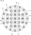
Fig. 4 is a front view as seen in the direction of line IV-IV inFig. 2 ; -
Fig. 5 is an enlarged view showing a part ofFig. 3 ; -
Fig. 6 is an enlarged view showing a specific part ofFig. 2 ; -
Fig. 7 is a sectional view along line VII-VII inFig. 2 ; -
Fig. 8 is an enlarged sectional view showing a part of a combustor according to the second embodiment of the present invention; -
Fig. 9 is an enlarged sectional view showing a part of a combustor according to the third embodiment of the present invention; -
Fig. 10 is a back view as seen in the direction of line X-X inFig. 9 ; -
Fig. 11 is a circumferential-direction sectional view showing a part of swirl vanes of the combustor; -
Fig. 12 is a perspective view of a fuel injector of a combustor according to the fourth embodiment of the present invention, as seen obliquely from the upstream side; -
Fig. 13 is a back view of the fuel injector as seen from the downstream side; -
Fig. 14 is a back view showing arrangement of the fuel injectors; -
Fig. 15 is a perspective view showing the fuel injector as seen obliquely from the downstream side; -
Fig. 16 is a vertical sectional view of the fuel injectors; -
Fig. 17 is a schematic view showing a simulation result of the combustor according to the first embodiment; -
Fig. 18 is a schematic view showing a simulation result of the combustor according to the third embodiment; and -
Fig. 19 is a schematic view showing a simulation result of the combustor according to the fourth embodiment. - Hereinafter, embodiments according to the present invention will be described with reference to the drawings.
- A combustor according to the first embodiment of the present invention will be described with reference to
Figs. 1 to 7 . - As shown in
Fig. 1 , agas turbine engine 1 includes acompressor 2, acombustor 3, and aturbine 5 connected to thecompressor 2 via arotary shaft 4. Hereinafter, the gas turbine engine is simply referred to asgas turbine 1. - In the
gas turbine 1, introduced air is compressed by thecompressor 2 and guided to thecombustor 3, fuel is injected into thecombustor 3 so as to be combusted together with the air, and then theturbine 5 is driven by the obtained high-temperature high-pressure combustion gas. By the driving of theturbine 5, thecompressor 2 is driven. By output of thegas turbine 1, a load 6 such as an electric generator or a rotor of an aircraft is driven. As fuel to be injected into thecombustor 3, for example, hydrogen gas is used. In the following description, thecompressor 2 side in the axial direction of thegas turbine 1 is referred to as "front side", and theturbine 5 side in the axial direction of thegas turbine 1 is referred to as "rear side". - A plurality of the
combustors 3 are arranged around a rotation axis of thegas turbine 1, and as shown inFig. 2 , are supported by a main housing MH of the gas turbine 1 (Fig. 1 ). Eachcombustor 3 includes ahousing 7, acombustion liner 8, afuel injector 9, and ahousing chamber 10 housing thefuel injector 9. These components of thecombustor 3 may be made of, for example, metal having a light weight and heat resistance. - The
housing 7 is a substantially cylindrical member forming an outer barrel of thecombustor 3, and houses thecombustion liner 8. A spark plug P is attached near the middle portion in the longitudinal direction of thehousing 7, and a tip end of the spark plug P is inserted into acombustion chamber 8a in thecombustion liner 8. Thehousing 7 has a front end covered by anend cover 14, which is fixed by a plurality ofbolts 15. At a front end part in thehousing 7, thecylindrical housing chamber 10 is provided concentrically with thehousing 7. Thehousing chamber 10 is located upstream of thecombustion chamber 8a. Thecombustion liner 8 is provided so as to cylindrically extend from thehousing chamber 10, and thecombustion liner 8 and thehousing chamber 10 are provided concentrically with thehousing 7. - As shown in
Fig. 2 , anair introduction passage 16 is formed between thecombustion liner 8 forming thecombustion chamber 8a therein and thehousing 7 covering thecombustion liner 8. Theair introduction passage 16 introduces air A compressed by the compressor 2 (Fig. 1 ), into thehousing chamber 10. Thecombustor 3 is formed in a reverse-flow type in which the flowing directions of the air A and the fuel F are opposite to each other. The fuel F and the air A injected into thecombustion chamber 8a are ignited by the spark plug P, whereby flame is formed in thecombustion chamber 8a. - As shown in
Fig. 2 , thehousing chamber 10 is located upstream of thecombustion chamber 8a and houses a plurality of thefuel injectors 9. Thesefuel injectors 9 are provided at a top portion (most upstream portion) of thecombustion liner 8, and inject the fuel F into thecombustion chamber 8a. Eachfuel injector 9 includes a bottomed-tubularfuel supply tube 11 which penetrates through thehousing chamber 10 and supplies the fuel F to thecombustion chamber 8a, and atubular guide member 12 provided on the outer side of a downstream end of thefuel supply tube 11. Theguide member 12 has a cylindrical shape as viewed in the direction of an axis C2 of thefuel supply tube 11. Thefuel supply tube 11 and theguide member 12 are concentric with each other, and connected by aconnection wall 13. Apartition wall 17 is provided for partitioning thehousing chamber 10 and thecombustion chamber 8a from each other, and a plurality of theguide members 12 are attached to thepartition wall 17 so as to penetrate therethrough. Thefuel supply tube 11 and theguide member 12, and theconnection wall 13 are welded to each other, and theguide member 12 and thepartition wall 17 are also welded to each other. - As shown in
Fig. 6 , a plurality of fuel injection holes 18 are provided in a circumferential wall of thefuel supply tube 11, on a slightly downstream side of theconnection wall 13. The plurality of the fuel injection holes 18 are arranged at equal intervals in the circumferential wall of thefuel supply tube 11. The air A is supplied from the upstream side to the fuel F which has been injected from the fuel injection holes 18. As shown inFig. 5 , a plurality ofguide grooves 20 for allowing air to pass therethrough are formed in theconnection wall 13. The plurality ofguide grooves 20 are arranged at equal intervals in the circumferential direction. Eachfuel injection hole 18 faces the downstream side of theguide groove 20. Theguide member 12 is formed by acylindrical guide tube 12A, and theguide groove 20 that thefuel injection hole 18 faces is formed on the inner side of theguide tube 12A. - As shown in
Fig. 3 , thefuel injectors 9 are arranged at approximately equal intervals in a grid pattern in thehousing chamber 10. As shown inFig. 6 , the fuel F is injected to the inner side of theguide member 12 from the plurality of fuel injection holes 18 of thefuel supply tube 11, and the fuel F injected from the fuel injection holes 18 is mixed into the air A supplied through theguide groove 20 from the upstream side. In this example, eachfuel injection hole 18 opens in a direction of 0° with respect to a radial direction R1 of thefuel supply tube 11, i.e., opens along the radial direction R1. However, the opening angle of thefuel injection hole 18 is not limited to 0°. In this example, theguide member 12 is provided so that the air flow-out direction thereof has an angle of 90° with respect to the fuel injection holes 18. - As shown in
Fig. 2 , upstream portions of thefuel supply tubes 11 are supported by theend cover 14, and downstream portions thereof are supported by thepartition wall 17 via theguide members 12 and theconnection walls 13. Thefuel supply tubes 11 are arranged such that the directions of the axes C2 thereof are parallel to the direction of an axis C1 of thehousing chamber 10 and thefuel supply tubes 11 are distant from each other by a predetermined interval. - In this example, as shown in
Fig. 4 , the fuel F is supplied from the outside to each set of predetermined threefuel supply tubes 11 adjacent to each other. Upstream portions of thefuel supply tubes 11 in each set communicate with each other via acommunication path 21, and thecommunication path 21 communicates with afuel supply port 22 protruding from theend cover 14. The fuel F is supplied from eachfuel supply port 22. - As shown in
Fig. 2 , adistribution plate 23 for air is provided at a part where thehousing chamber 10 and theair introduction passage 16 communicate with each other. Thedistribution plate 23 is formed in a cylindrical shape concentric with the direction of the axis C1 of thecombustion liner 8. As shown inFig. 7 , thedistribution plate 23 has a circumferential wall formed with a plurality of throughholes 23a penetrating the circumferential wall in the radial direction. The throughholes 23a are arranged at predetermined intervals in the circumferential direction and the axial direction. As shown inFig. 2 , the air A introduced from theair introduction passage 16 passes through the plurality of throughholes 23a (Fig. 7 ) of thedistribution plate 23, whereby the air A is formed into uniformly distributed flow on the downstream side of thedistribution plate 23. - In the
combustor 3 of thegas turbine 1, the plurality offuel supply tubes 11 shown inFig. 2 are arranged spaced from each other by a predetermined interval, and the plurality of fuel injection holes 18 are arranged in the circumferential direction at a downstream portion of eachfuel supply tube 11. Therefore, the fuel F is injected from thefuel injectors 9 uniformly over the entire area of thecombustion chamber 8a. Thus, on all the surfaces of thefuel injectors 9, minute flames are held at multiple points. Accordingly, occurrence of local high-temperature combustion is prevented, and generation of NOx can be suppressed. In addition, since the air A is supplied from the upstream side to the fuel F injected from the fuel injection holes 18, the flames do not enter the inner sides of thefuel injectors 9, whereby a backfire phenomenon is suppressed. - Each
fuel supply tube 11 penetrates through thehousing chamber 10 and supplies the fuel F to thecombustion chamber 8a. At a downstream portion of thefuel supply tube 11, the fuel injection holes 18 are provided for injecting the fuel F to the inner side of theguide member 12 so as to mix the fuel F with the air A, and the air A and the fuel F are supplied from theguide member 12 to thecombustion chamber 8a. As described above, with a simplified structure of the supply path for the fuel F leading from thefuel supply tube 11 to theguide member 12, the air A and the fuel F are supplied from theguide member 12 to thecombustion chamber 8a. Therefore, as compared to the conventional structure (JP Patent No. 6285081 - The
air introduction passage 16 for introducing the air A into thehousing chamber 10 is formed between thecombustion liner 8 and thehousing 7. Therefore, the structure can be made in a reverse-flow type in which the flowing directions of the air A and the fuel F are opposite to each other. Thus, the entire device can be further made compact in the axial direction. - The
guide groove 20 that the fuel injection holes 18 face is formed on the inner side of theguide member 12. Therefore, the air A introduced to the inner side of theguide member 12 increases in the flow speed when passing through theguide groove 20, and as a result, the fuel F is smoothly sucked into the air A, so that mixture with the air A is promoted. - The fuel injection holes 18 open in a direction of 0° with respect to the radial direction R1 of the
fuel supply tube 11. Therefore, the manufacturing cost can be reduced. Theguide member 12 opens in a direction of 0° with respect to the axis C2 of thefuel supply tube 11. Therefore, the passage in theguide member 12, i.e., the air flow-out direction has an angle of 90° with respect to the fuel injection holes 18, so that the air A transversely crosses the fuel F, thus promoting mixture of the air A and the fuel F. - In the following description, when only part of the structure is described, the other part of the structure is the same as that previously described.
- As shown in
Fig. 8 , thefuel injection hole 18 may be provided on the upstream side of theguide groove 20. In this example, the fuel injection holes 18 open so as to be inclined toward the downstream side by a predetermined angle α with respect to the radial direction R1 of thefuel supply tube 11. The angle α is 0 to 30° (+30°). Regarding the angle α, the inclination angle of the fuel injection holes 18 in a case where the fuel injection holes 18 are inclined toward the downstream side in the axial direction as approaching toward the outer side in the radial direction, is defined as a "positive" inclination angle. - The
guide groove 20 of theguide member 12 opens in a direction of a predetermined angle β with respect to the axis C2 of thefuel supply tube 11. The angle β is a to 30° (+30°). Regarding the angle β, the inclination angle in a case where theguide groove 20 is inclined outward in the radial direction as approaching the upstream side, is defined as a "positive" inclination angle. - The passage direction of the
guide groove 20 of theguide member 12 has a predetermined angle γ with respect to the fuel injection holes 18. The angle γ is 60° to 90°. - The angles α, β, γ are angles arbitrarily determined in accordance with designing or the like, and for example, determined by finding appropriate angles through one or both of a test and a simulation, or the like.
- Since the fuel injection holes 18 open in a direction of 0 to 30° with respect to the radial direction R1 of the
fuel supply tube 11, the manufacturing cost can be reduced. Since theguide groove 20 of theguide member 12 opens in a direction of 0 to 30° with respect to the axis C2 of thefuel supply tube 11, the air A and the fuel F are favorably mixed to be supplied to thecombustion chamber 8a. Since the passage direction of theguide member 12 has an angle of 60° to 90° with respect to the fuel injection holes 18, the fuel F is smoothly injected, whereby the air A and the fuel F can be uniformly mixed. - Also in the structure (see
Fig. 6 ) in which thefuel injection hole 18 is provided on the downstream side of theguide groove 20, it is preferable that the angle α is 0 to 30°, the angle β is 0 to 30°, and the angle γ is 60° to 90°. - As shown in
Fig. 9 and Fig. 10 , on the inner side of theguide member 12, fixedswirl vanes 24 are provided for swirl the air A passing between theconnection wall 13 and thefuel supply tube 11 around in theguide tube 12A. The swirl vanes 24 are formed by a plurality of inclined vanes 26 (Fig. 11 ) fixed between the inner and outer rings, and are generally called a swirler. As shown inFig. 11 (sectional view along line XI-XI inFig. 9 ), thevanes 26 are inclined by an inclination angle δ with respect to the axis C2 of the guide member 12 (Fig. 10 ). The inclination angle δ is 15° to 45°, and preferably, 20° to 40°. - In this structure, by the
swirl vanes 24, mixture of the air A and the fuel F is promoted and a swirl is formed inside thecombustion chamber 8a, whereby a stable flame is obtained. It is noted that, if the inclination angle δ of thevanes 26 is greater than 45°, the swirl becomes excessively strong, so that the speed of downstream advancement of mixture gas of the air A and the fuel F is reduced and thus a backfire phenomenon might occur. -
Fig. 12 to Fig. 15 show thefuel injector 9 of the present embodiment. InFig. 12 , aguide member 12B in this example has aguide wall 27 having a hexagonal shape as seen in the direction of the axis C2 of thefuel supply tube 11, and an outerperipheral protrusion 28 joined to the outer peripheral surface of theguide wall 27. As shown inFig. 13 , the outerperipheral protrusion 28 is formed in a hexagonal frame shape in a front view. As shown inFig. 14 , outer edges of a plurality of outerperipheral protrusions 28 adjacent to each other in the radial direction are joined to each other without gaps, whereby a plurality offuel injectors 9 are arranged in a honeycomb shape. The outerperipheral protrusions 28 located on the radially outermost side inFig. 14 are joined to thepartition wall 17. The above joining for each part is made by welding, for example. - As shown in
Fig. 12 , thefuel supply tube 11 has a cylindrical fuelsupply tube body 11a and a bottomed hexagonalcylindrical box 29 connected to a downstream end of the fuelsupply tube body 11a. As shown inFig. 16 , thebox 29 communicates with the fuelsupply tube body 11a and is concentric with the fuelsupply tube body 11a. Thebox 29 and theguide wall 27 are concentric with each other and connected by theconnection wall 13. - The fuel injection holes 18 are provided in a peripheral wall of the
box 29, on a slightly downstream side of theconnection wall 13. As shown inFig. 15 , a plurality of fuel injection holes 18 are arranged at predetermined intervals in the peripheral wall of thebox 29. Eachfuel injection hole 18 faces the downstream side of theguide groove 20 formed in theconnection wall 13. As shown inFig. 16 , the fuel injection holes 18 in this example open in directions respectively perpendicular to the outer peripheral wall surfaces of the hexagonal tube of thebox 29. Theguide wall 27 extends in parallel to the axis C2 of the fuelsupply tube body 11a. - As described above, the plurality of
fuel injectors 9 are arranged densely in a honeycomb shape. Therefore,more fuel injectors 9 than in the other embodiments are arranged, whereby mixture of the air A and the fuel F can be more uniformed. The fuel injection holes 18 open in directions respectively perpendicular to the outer peripheral wall surfaces of the hexagonal tube of thebox 29, whereby the manufacturing cost can be reduced. Since theguide wall 27 extends in parallel to the axis C2 of the fuelsupply tube body 11a, the passage direction of theguide wall 27, i.e., the air flow-out direction has an angle of 90° with respect to thefuel injection hole 18. Therefore, the air A transversely crosses the fuel F, thus promoting mixture of the air A and the fuel F. Besides, the same operations and effects as in the above embodiments are provided. It is noted that theguide wall 27 is not limited to a hexagonal shape, but may be a polygonal shape with three or more sides. -
Fig. 17 shows a simulation result of the combustor according to the first embodiment (Figs. 2 to 7 ). In the simulation inFig. 17 , a protruding portion 12Aa (indicated by a two-dot dashed line inFig. 6 ) which is a downstream end of theguide tube 12A slightly extends toward the downstream side with respect to a downstream end of thefuel supply tube 11. According to the simulation result, inside thecombustion chamber 8a, a vortex V1 is generated in a low-pressure area 8aa arising on the downstream side of thefuel supply tube 11. Radial-direction expansion of the vortex V1 is suppressed by the air A passing through theguide groove 20, and mixture of the fuel F and the air A in the low-pressure area 8aa is promoted. In addition, the size of a backflow vortex V2 generated in a low-pressure area 8ab on the downstream side of the protruding portion 12Aa is ensured, and mixture in the low-pressure area 8ab is also promoted. Thus, combustion gas is readily uniformed, so that the flames are stabilized. - According to a simulation result of the combustor in the third embodiment (
Fig. 9 to Fig. 11 ) shown inFig. 18 , a swirl RV is formed on the downstream side of thefuel supply tube 11 by theswirl vanes 24 and the mixture gas expands in the radial direction, so that a backflow area is formed. Thus,stable flames 31 extending toward the downstream side are obtained. - According to a simulation result of the combustor of a honeycomb burner type in the fourth embodiment (
Fig. 12 to 16 ) shown inFig. 19 , inside thecombustion chamber 8a, a backflow vortex V3 is generated on the downstream side of thebox 29, and as a result, the combustion gas can be uniformed and the flames are stabilized. - In the present invention, in a case of a small-
sized combustor 3, the number of thefuel supply tubes 11 may be one. - The fuel F used in the
combustor 3 is not limited to hydrogen gas. For example, the fuel F may be mixture fuel of hydrogen gas and another fuel gas (natural gas, CO, etc.) or may be another fuel gas (natural gas, CO, etc.) not including hydrogen. - Although the present invention has been described above in connection with the preferred embodiments with reference to the accompanying drawings, numerous additions, modifications, or deletions can be made without departing from the gist of the present invention. Accordingly, such additions, modifications, or deletions are to be construed as included in the scope of the present invention.
-
- 1
- gas turbine
- 3
- combustor
- 7
- housing
- 8
- combustion liner
- 8a
- combustion chamber
- 9
- fuel injector
- 10
- housing chamber
- 11
- fuel supply tube
- 12, 12B
- guide member
- 16
- air introduction passage
- 18
- fuel injection hole
- 20
- guide groove
- 23
- distribution plate
- 24
- swirl vane
- A
- air
- F
- fuel
Claims (6)
- A gas turbine (1) combustor (3) comprising:a combustion liner (8) forming a combustion chamber (8a);a fuel injector (9) provided at an upstream portion of the combustion liner (8); anda housing chamber (10) located upstream of the combustion chamber (8a) and housing the fuel injector (9), whereinthe fuel injector (9) includesa fuel supply tube (11) penetrating through the housing chamber (10) and configured to supply fuel to the combustion chamber (8), anda guide member (12) provided on an outer side of a downstream portion of the fuel supply tube (11), the guide member (12) being configured to allow air to pass therethrough,the fuel supply tube (11) and the guide member (12) are connected by a connection wall (13),the fuel supply tube (11) includes, in the downstream portion thereof, a plurality of fuel injection holes (18) arranged at equal intervals in the circumferential direction of the fuel supply tube and configured to inject fuel to the air passing through the guide member (12) therein, so as to mix the fuel with the air, a plurality of guide grooves (20) that the fuel injection hole (18) faces are formed on the connection wall (13), the guide grooves (20) being arranged at equal intervals in the circumferential direction of the guide member (12), andthe guide member (12) is configured to supply the air and the fuel therefrom into the combustion chamber (8a).
- The gas turbine combustor as claimed in claim 1, further comprising an air introduction passage (16) formed between the combustion liner (8) and a housing covering the combustion liner (8), and configured to introduce the air into the housing chamber (10).
- The gas turbine combustor as claimed in claim 2, further comprising a distribution plate (23) for the air, provided at a part where the housing chamber (10) and the air introduction passage (16) communicate with each other.
- The gas turbine combustor as claimed in any one of claims 1 to 3, wherein the guide member (12) has a cylindrical shape or a polygonal shape as viewed in an axial direction of the fuel supply tube (11).
- The gas turbine combustor as claimed in claim 4, whereinthe fuel injection holes (18) open in a direction of 0 to 30° with respect to a radial direction of the fuel supply tube (11),the guide groove (20) of the guide member (12) opens in a direction of 0 to 30° with respect to the axial direction of the fuel supply tube (11), andthe fuel injector (9) is configured such that an air flow-out direction from the guide groove (20) has an angle of 60° to 90° with respect to the fuel injection hole (18).
- The gas turbine combustor as claimed in claim 4 or 5, further comprising a fixed swirl vane (24) provided on an inner side of the guide member (12) and configured to swirl the air passing between the guide member (12) and the fuel supply tube (11) around the guide member (12).
Applications Claiming Priority (1)
| Application Number | Priority Date | Filing Date | Title |
|---|---|---|---|
| CN202010294542.XA CN113531584B (en) | 2020-04-15 | 2020-04-15 | Combustion device of gas turbine |
Publications (3)
| Publication Number | Publication Date |
|---|---|
| EP3896341A1 EP3896341A1 (en) | 2021-10-20 |
| EP3896341C0 EP3896341C0 (en) | 2023-06-07 |
| EP3896341B1 true EP3896341B1 (en) | 2023-06-07 |
Family
ID=75441735
Family Applications (1)
| Application Number | Title | Priority Date | Filing Date |
|---|---|---|---|
| EP21167537.6A Active EP3896341B1 (en) | 2020-04-15 | 2021-04-09 | Gas turbine combustor |
Country Status (4)
| Country | Link |
|---|---|
| US (1) | US11365885B2 (en) |
| EP (1) | EP3896341B1 (en) |
| JP (1) | JP7150260B2 (en) |
| CN (1) | CN113531584B (en) |
Families Citing this family (10)
| Publication number | Priority date | Publication date | Assignee | Title |
|---|---|---|---|---|
| KR102490477B1 (en) * | 2021-02-03 | 2023-01-19 | 두산에너빌리티 주식회사 | Discharge-nozzle, Combustor and Gas turbine comprising the same |
| KR20230091605A (en) * | 2021-12-16 | 2023-06-23 | 한화에어로스페이스 주식회사 | Burner including channel arranged orthogonally |
| US11828465B2 (en) * | 2022-01-21 | 2023-11-28 | General Electric Company | Combustor fuel assembly |
| KR102607177B1 (en) | 2022-01-28 | 2023-11-29 | 두산에너빌리티 주식회사 | Nozzle for combustor, combustor, and gas turbine including the same |
| KR102583223B1 (en) * | 2022-01-28 | 2023-09-25 | 두산에너빌리티 주식회사 | Nozzle for combustor, combustor, and gas turbine including the same |
| KR102583225B1 (en) * | 2022-02-07 | 2023-09-25 | 두산에너빌리티 주식회사 | Micromixer and gas turbine comprising the same |
| KR102583226B1 (en) | 2022-02-07 | 2023-09-25 | 두산에너빌리티 주식회사 | Micromixer with multi-stage fuel supply and gas turbine including same |
| JP7833182B2 (en) * | 2022-06-14 | 2026-03-19 | 国立研究開発法人宇宙航空研究開発機構 | Hydrogen combustors, hydrogen combustor systems, jet engines, and power generation equipment |
| CN116293800B (en) * | 2023-02-24 | 2025-03-14 | 北京航空航天大学 | Combustion chamber mild mixing head, gas turbine combustion chamber and gas turbine |
| JP2024169002A (en) * | 2023-05-25 | 2024-12-05 | 川崎重工業株式会社 | Burner and combustor |
Family Cites Families (27)
| Publication number | Priority date | Publication date | Assignee | Title |
|---|---|---|---|---|
| US3831854A (en) * | 1973-02-23 | 1974-08-27 | Hitachi Ltd | Pressure spray type fuel injection nozzle having air discharge openings |
| JPS59108054U (en) * | 1983-01-07 | 1984-07-20 | 株式会社東芝 | Fuel/air premixing device |
| JPS6076729U (en) * | 1983-11-02 | 1985-05-29 | 株式会社日立製作所 | fuel nozzle |
| JP3012166B2 (en) | 1995-02-01 | 2000-02-21 | 川崎重工業株式会社 | Gas turbine combustion system |
| JPH09166326A (en) * | 1995-12-15 | 1997-06-24 | Hitachi Ltd | Gas turbine combustor |
| JPH11211086A (en) * | 1998-01-21 | 1999-08-06 | Hitachi Ltd | Gas turbine combustor |
| US7143583B2 (en) | 2002-08-22 | 2006-12-05 | Hitachi, Ltd. | Gas turbine combustor, combustion method of the gas turbine combustor, and method of remodeling a gas turbine combustor |
| JP3940705B2 (en) * | 2003-06-19 | 2007-07-04 | 株式会社日立製作所 | Gas turbine combustor and fuel supply method thereof |
| JP4728176B2 (en) | 2005-06-24 | 2011-07-20 | 株式会社日立製作所 | Burner, gas turbine combustor and burner cooling method |
| JP4934696B2 (en) | 2009-03-26 | 2012-05-16 | 株式会社日立製作所 | Burner and combustor |
| JP5472863B2 (en) * | 2009-06-03 | 2014-04-16 | 独立行政法人 宇宙航空研究開発機構 | Staging fuel nozzle |
| US20120085834A1 (en) * | 2010-10-07 | 2012-04-12 | Abdul Rafey Khan | Flame Tolerant Primary Nozzle Design |
| JP5393745B2 (en) | 2011-09-05 | 2014-01-22 | 川崎重工業株式会社 | Gas turbine combustor |
| US9341376B2 (en) * | 2012-02-20 | 2016-05-17 | General Electric Company | Combustor and method for supplying fuel to a combustor |
| US8701419B2 (en) * | 2012-05-10 | 2014-04-22 | General Electric Company | Multi-tube fuel nozzle with mixing features |
| US9546789B2 (en) * | 2013-03-15 | 2017-01-17 | General Electric Company | System having a multi-tube fuel nozzle |
| JP6474951B2 (en) * | 2013-04-10 | 2019-02-27 | 三菱日立パワーシステムズ株式会社 | Combustor |
| WO2015182154A1 (en) | 2014-05-30 | 2015-12-03 | Kawasaki Jukogyo Kabushiki Kaisha | Combustor for gas turbine engine |
| WO2015182727A1 (en) * | 2014-05-30 | 2015-12-03 | 川崎重工業株式会社 | Combustion device for gas turbine engine |
| US10288291B2 (en) * | 2014-08-15 | 2019-05-14 | General Electric Company | Air-shielded fuel injection assembly to facilitate reduced NOx emissions in a combustor system |
| JP6422412B2 (en) * | 2015-09-10 | 2018-11-14 | 三菱日立パワーシステムズ株式会社 | Gas turbine combustor |
| JP6638935B2 (en) * | 2015-12-22 | 2020-02-05 | 川崎重工業株式会社 | Fuel injection device |
| JP6621658B2 (en) * | 2015-12-22 | 2019-12-18 | 川崎重工業株式会社 | Fuel injection device |
| AU2017296362B2 (en) * | 2016-07-15 | 2023-04-13 | Aerostrovilos Energy Pvt Ltd | A swirl mesh lean direct injection concept for distributed flame holding for low pollutant emissions and mitigation of combustion instability |
| JP6822894B2 (en) | 2017-04-28 | 2021-01-27 | 三菱パワー株式会社 | Fuel injector and gas turbine |
| KR102063169B1 (en) * | 2017-07-04 | 2020-01-07 | 두산중공업 주식회사 | Fuel nozzle assembly and combustor and gas turbine having the same |
| US10954859B2 (en) * | 2017-07-25 | 2021-03-23 | Raytheon Technologies Corporation | Low emissions combustor assembly for gas turbine engine |
-
2020
- 2020-04-15 CN CN202010294542.XA patent/CN113531584B/en active Active
- 2020-07-17 JP JP2020122937A patent/JP7150260B2/en active Active
-
2021
- 2021-04-09 US US17/226,805 patent/US11365885B2/en active Active
- 2021-04-09 EP EP21167537.6A patent/EP3896341B1/en active Active
Also Published As
| Publication number | Publication date |
|---|---|
| EP3896341C0 (en) | 2023-06-07 |
| US11365885B2 (en) | 2022-06-21 |
| EP3896341A1 (en) | 2021-10-20 |
| CN113531584B (en) | 2023-05-23 |
| JP2021169913A (en) | 2021-10-28 |
| JP7150260B2 (en) | 2022-10-11 |
| US20210325046A1 (en) | 2021-10-21 |
| CN113531584A (en) | 2021-10-22 |
Similar Documents
| Publication | Publication Date | Title |
|---|---|---|
| US11365885B2 (en) | Gas turbine combustor with fuel injector including a downstream guide member | |
| CN101672483B (en) | Gas turbine | |
| EP2405201B1 (en) | Injection nozzle for a turbomachine | |
| US8113001B2 (en) | Tubular fuel injector for secondary fuel nozzle | |
| EP3149407B1 (en) | Combustor for gas turbine engine | |
| EP3150918B1 (en) | Combustion device for gas turbine engine | |
| EP2309188B1 (en) | Combustion device and control method thereof | |
| US9612013B2 (en) | Gas turbine combustor | |
| EP2725303A2 (en) | Reheat burner arrangement | |
| JP2006300448A (en) | Combustor for gas turbine | |
| JP2018004138A (en) | Gas turbine combustor | |
| US11371707B2 (en) | Combustor and gas turbine including the same | |
| KR102512583B1 (en) | Gas turbine combustor and gas turbine equipped with the same | |
| CN113464979B (en) | Compact turbine burners | |
| US10697639B2 (en) | Dual-fuel fuel nozzle with liquid fuel tip | |
| JP3192055B2 (en) | Gas turbine combustor | |
| KR20250022885A (en) | Burner assembly, gas turbine combustor, and gas turbine | |
| EP3425280B1 (en) | Combustor and gas turbine | |
| US12449130B2 (en) | Combustor and gas turbine | |
| JP7642805B2 (en) | Gas Turbine Combustor | |
| WO2025037503A1 (en) | Fuel supply pipe assembly, gas turbine combustor, and gas turbine | |
| WO2025239137A1 (en) | Fuel manifold, gas turbine combustor, and gas turbine | |
| KR20230147523A (en) | Fuel supply pipe assembly, gas turbine combustor, and gas turbine | |
| JP2025084431A (en) | Combustion equipment and gas turbine systems | |
| JP2008298350A (en) | Combustion device for gas turbine engine |
Legal Events
| Date | Code | Title | Description |
|---|---|---|---|
| PUAI | Public reference made under article 153(3) epc to a published international application that has entered the european phase |
Free format text: ORIGINAL CODE: 0009012 |
|
| STAA | Information on the status of an ep patent application or granted ep patent |
Free format text: STATUS: REQUEST FOR EXAMINATION WAS MADE |
|
| 17P | Request for examination filed |
Effective date: 20210409 |
|
| AK | Designated contracting states |
Kind code of ref document: A1 Designated state(s): AL AT BE BG CH CY CZ DE DK EE ES FI FR GB GR HR HU IE IS IT LI LT LU LV MC MK MT NL NO PL PT RO RS SE SI SK SM TR |
|
| B565 | Issuance of search results under rule 164(2) epc |
Effective date: 20210915 |
|
| GRAP | Despatch of communication of intention to grant a patent |
Free format text: ORIGINAL CODE: EPIDOSNIGR1 |
|
| STAA | Information on the status of an ep patent application or granted ep patent |
Free format text: STATUS: GRANT OF PATENT IS INTENDED |
|
| INTG | Intention to grant announced |
Effective date: 20221215 |
|
| GRAS | Grant fee paid |
Free format text: ORIGINAL CODE: EPIDOSNIGR3 |
|
| GRAA | (expected) grant |
Free format text: ORIGINAL CODE: 0009210 |
|
| STAA | Information on the status of an ep patent application or granted ep patent |
Free format text: STATUS: THE PATENT HAS BEEN GRANTED |
|
| AK | Designated contracting states |
Kind code of ref document: B1 Designated state(s): AL AT BE BG CH CY CZ DE DK EE ES FI FR GB GR HR HU IE IS IT LI LT LU LV MC MK MT NL NO PL PT RO RS SE SI SK SM TR |
|
| REG | Reference to a national code |
Ref country code: GB Ref legal event code: FG4D |
|
| REG | Reference to a national code |
Ref country code: CH Ref legal event code: EP Ref country code: AT Ref legal event code: REF Ref document number: 1576118 Country of ref document: AT Kind code of ref document: T Effective date: 20230615 Ref country code: DE Ref legal event code: R096 Ref document number: 602021002654 Country of ref document: DE |
|
| U01 | Request for unitary effect filed |
Effective date: 20230607 |
|
| U07 | Unitary effect registered |
Designated state(s): AT BE BG DE DK EE FI FR IT LT LU LV MT NL PT SE SI Effective date: 20230612 |
|
| REG | Reference to a national code |
Ref country code: LT Ref legal event code: MG9D |
|
| PG25 | Lapsed in a contracting state [announced via postgrant information from national office to epo] |
Ref country code: NO Free format text: LAPSE BECAUSE OF FAILURE TO SUBMIT A TRANSLATION OF THE DESCRIPTION OR TO PAY THE FEE WITHIN THE PRESCRIBED TIME-LIMIT Effective date: 20230907 Ref country code: ES Free format text: LAPSE BECAUSE OF FAILURE TO SUBMIT A TRANSLATION OF THE DESCRIPTION OR TO PAY THE FEE WITHIN THE PRESCRIBED TIME-LIMIT Effective date: 20230607 |
|
| PG25 | Lapsed in a contracting state [announced via postgrant information from national office to epo] |
Ref country code: RS Free format text: LAPSE BECAUSE OF FAILURE TO SUBMIT A TRANSLATION OF THE DESCRIPTION OR TO PAY THE FEE WITHIN THE PRESCRIBED TIME-LIMIT Effective date: 20230607 Ref country code: HR Free format text: LAPSE BECAUSE OF FAILURE TO SUBMIT A TRANSLATION OF THE DESCRIPTION OR TO PAY THE FEE WITHIN THE PRESCRIBED TIME-LIMIT Effective date: 20230607 |
|
| U1N | Appointed representative for the unitary patent procedure changed after the registration of the unitary effect |
Representative=s name: PACT-IP; FR |
|
| PG25 | Lapsed in a contracting state [announced via postgrant information from national office to epo] |
Ref country code: SK Free format text: LAPSE BECAUSE OF FAILURE TO SUBMIT A TRANSLATION OF THE DESCRIPTION OR TO PAY THE FEE WITHIN THE PRESCRIBED TIME-LIMIT Effective date: 20230607 |
|
| PG25 | Lapsed in a contracting state [announced via postgrant information from national office to epo] |
Ref country code: IS Free format text: LAPSE BECAUSE OF FAILURE TO SUBMIT A TRANSLATION OF THE DESCRIPTION OR TO PAY THE FEE WITHIN THE PRESCRIBED TIME-LIMIT Effective date: 20231007 |
|
| PG25 | Lapsed in a contracting state [announced via postgrant information from national office to epo] |
Ref country code: SM Free format text: LAPSE BECAUSE OF FAILURE TO SUBMIT A TRANSLATION OF THE DESCRIPTION OR TO PAY THE FEE WITHIN THE PRESCRIBED TIME-LIMIT Effective date: 20230607 Ref country code: SK Free format text: LAPSE BECAUSE OF FAILURE TO SUBMIT A TRANSLATION OF THE DESCRIPTION OR TO PAY THE FEE WITHIN THE PRESCRIBED TIME-LIMIT Effective date: 20230607 Ref country code: RO Free format text: LAPSE BECAUSE OF FAILURE TO SUBMIT A TRANSLATION OF THE DESCRIPTION OR TO PAY THE FEE WITHIN THE PRESCRIBED TIME-LIMIT Effective date: 20230607 Ref country code: IS Free format text: LAPSE BECAUSE OF FAILURE TO SUBMIT A TRANSLATION OF THE DESCRIPTION OR TO PAY THE FEE WITHIN THE PRESCRIBED TIME-LIMIT Effective date: 20231007 Ref country code: CZ Free format text: LAPSE BECAUSE OF FAILURE TO SUBMIT A TRANSLATION OF THE DESCRIPTION OR TO PAY THE FEE WITHIN THE PRESCRIBED TIME-LIMIT Effective date: 20230607 |
|
| PG25 | Lapsed in a contracting state [announced via postgrant information from national office to epo] |
Ref country code: PL Free format text: LAPSE BECAUSE OF FAILURE TO SUBMIT A TRANSLATION OF THE DESCRIPTION OR TO PAY THE FEE WITHIN THE PRESCRIBED TIME-LIMIT Effective date: 20230607 |
|
| REG | Reference to a national code |
Ref country code: DE Ref legal event code: R097 Ref document number: 602021002654 Country of ref document: DE |
|
| PLBE | No opposition filed within time limit |
Free format text: ORIGINAL CODE: 0009261 |
|
| STAA | Information on the status of an ep patent application or granted ep patent |
Free format text: STATUS: NO OPPOSITION FILED WITHIN TIME LIMIT |
|
| 26N | No opposition filed |
Effective date: 20240308 |
|
| U20 | Renewal fee for the european patent with unitary effect paid |
Year of fee payment: 4 Effective date: 20240423 |
|
| U1N | Appointed representative for the unitary patent procedure changed after the registration of the unitary effect |
Representative=s name: BANDPAY & GREUTER; FR |
|
| PG25 | Lapsed in a contracting state [announced via postgrant information from national office to epo] |
Ref country code: MC Free format text: LAPSE BECAUSE OF FAILURE TO SUBMIT A TRANSLATION OF THE DESCRIPTION OR TO PAY THE FEE WITHIN THE PRESCRIBED TIME-LIMIT Effective date: 20230607 |
|
| PG25 | Lapsed in a contracting state [announced via postgrant information from national office to epo] |
Ref country code: MC Free format text: LAPSE BECAUSE OF FAILURE TO SUBMIT A TRANSLATION OF THE DESCRIPTION OR TO PAY THE FEE WITHIN THE PRESCRIBED TIME-LIMIT Effective date: 20230607 |
|
| REG | Reference to a national code |
Ref country code: CH Ref legal event code: PL |
|
| PG25 | Lapsed in a contracting state [announced via postgrant information from national office to epo] |
Ref country code: CH Free format text: LAPSE BECAUSE OF NON-PAYMENT OF DUE FEES Effective date: 20240430 |
|
| PG25 | Lapsed in a contracting state [announced via postgrant information from national office to epo] |
Ref country code: IE Free format text: LAPSE BECAUSE OF NON-PAYMENT OF DUE FEES Effective date: 20240409 |
|
| U20 | Renewal fee for the european patent with unitary effect paid |
Year of fee payment: 5 Effective date: 20250422 |
|
| PG25 | Lapsed in a contracting state [announced via postgrant information from national office to epo] |
Ref country code: CY Free format text: LAPSE BECAUSE OF FAILURE TO SUBMIT A TRANSLATION OF THE DESCRIPTION OR TO PAY THE FEE WITHIN THE PRESCRIBED TIME-LIMIT; INVALID AB INITIO Effective date: 20210409 |
|
| PG25 | Lapsed in a contracting state [announced via postgrant information from national office to epo] |
Ref country code: HU Free format text: LAPSE BECAUSE OF FAILURE TO SUBMIT A TRANSLATION OF THE DESCRIPTION OR TO PAY THE FEE WITHIN THE PRESCRIBED TIME-LIMIT; INVALID AB INITIO Effective date: 20210409 |
|
| PG25 | Lapsed in a contracting state [announced via postgrant information from national office to epo] |
Ref country code: GR Free format text: LAPSE BECAUSE OF FAILURE TO SUBMIT A TRANSLATION OF THE DESCRIPTION OR TO PAY THE FEE WITHIN THE PRESCRIBED TIME-LIMIT; INVALID AB INITIO Effective date: 20210409 |
|
| GBPC | Gb: european patent ceased through non-payment of renewal fee |
Effective date: 20250409 |
|
| PG25 | Lapsed in a contracting state [announced via postgrant information from national office to epo] |
Ref country code: GB Free format text: LAPSE BECAUSE OF NON-PAYMENT OF DUE FEES Effective date: 20250409 |