EP3896302A1 - Driving mechanism used in a railway welding machine that operates along a railway track - Google Patents
Driving mechanism used in a railway welding machine that operates along a railway track Download PDFInfo
- Publication number
- EP3896302A1 EP3896302A1 EP20169788.5A EP20169788A EP3896302A1 EP 3896302 A1 EP3896302 A1 EP 3896302A1 EP 20169788 A EP20169788 A EP 20169788A EP 3896302 A1 EP3896302 A1 EP 3896302A1
- Authority
- EP
- European Patent Office
- Prior art keywords
- coupling device
- shaft
- bush
- male
- transmission mechanism
- Prior art date
- Legal status (The legal status is an assumption and is not a legal conclusion. Google has not performed a legal analysis and makes no representation as to the accuracy of the status listed.)
- Granted
Links
Images







Classifications
-
- F—MECHANICAL ENGINEERING; LIGHTING; HEATING; WEAPONS; BLASTING
- F16—ENGINEERING ELEMENTS AND UNITS; GENERAL MEASURES FOR PRODUCING AND MAINTAINING EFFECTIVE FUNCTIONING OF MACHINES OR INSTALLATIONS; THERMAL INSULATION IN GENERAL
- F16D—COUPLINGS FOR TRANSMITTING ROTATION; CLUTCHES; BRAKES
- F16D11/00—Clutches in which the members have interengaging parts
- F16D11/08—Clutches in which the members have interengaging parts actuated by moving a non-rotating part axially
- F16D11/10—Clutches in which the members have interengaging parts actuated by moving a non-rotating part axially with clutching members movable only axially
-
- F—MECHANICAL ENGINEERING; LIGHTING; HEATING; WEAPONS; BLASTING
- F16—ENGINEERING ELEMENTS AND UNITS; GENERAL MEASURES FOR PRODUCING AND MAINTAINING EFFECTIVE FUNCTIONING OF MACHINES OR INSTALLATIONS; THERMAL INSULATION IN GENERAL
- F16D—COUPLINGS FOR TRANSMITTING ROTATION; CLUTCHES; BRAKES
- F16D1/00—Couplings for rigidly connecting two coaxial shafts or other movable machine elements
- F16D1/02—Couplings for rigidly connecting two coaxial shafts or other movable machine elements for connecting two abutting shafts or the like
- F16D1/04—Couplings for rigidly connecting two coaxial shafts or other movable machine elements for connecting two abutting shafts or the like with clamping hub; with hub and longitudinal key
-
- F—MECHANICAL ENGINEERING; LIGHTING; HEATING; WEAPONS; BLASTING
- F16—ENGINEERING ELEMENTS AND UNITS; GENERAL MEASURES FOR PRODUCING AND MAINTAINING EFFECTIVE FUNCTIONING OF MACHINES OR INSTALLATIONS; THERMAL INSULATION IN GENERAL
- F16D—COUPLINGS FOR TRANSMITTING ROTATION; CLUTCHES; BRAKES
- F16D1/00—Couplings for rigidly connecting two coaxial shafts or other movable machine elements
- F16D1/06—Couplings for rigidly connecting two coaxial shafts or other movable machine elements for attachment of a member on a shaft or on a shaft-end
- F16D1/08—Couplings for rigidly connecting two coaxial shafts or other movable machine elements for attachment of a member on a shaft or on a shaft-end with clamping hub; with hub and longitudinal key
- F16D1/0876—Couplings for rigidly connecting two coaxial shafts or other movable machine elements for attachment of a member on a shaft or on a shaft-end with clamping hub; with hub and longitudinal key with axial keys and no other radial clamping
Definitions
- the present invention relates to a driving mechanism used in a railway welding machine that operates along a railway track, more particularly a coupling mechanism.
- the repair of a railway track is important for public transportation construction. To secure the safety of passengers or goods, the railway track needs to be repaired and maintained on a regular basis. If a part of the railway track has a defect, a welding worker needs to cut off the defected part and rectify the railway track by welding, e.g., cladding.
- a railway welding machine with rollers can evenly distribute welding materials on the railway track.
- a conventional railway welding machine has several disadvantages.
- a conventional coupling mechanism for transmitting the force from the motor to the roller is not well structured in a conventional railway welding machine.
- the components of the driving mechanism cannot be easily and smoothly operated and are easily worn out. Therefore, the conventional driving mechanism of a railway welding machine needs to be frequently substituted and costs much time and money. Therefore, it is important to provide a driving mechanism used in a railway welding machine that operates along a railway track, and more particularly a coupling mechanism that can be replaced smoothly, is not worn out easily during operation, and is easily and smoothly coupled.
- the objective of the present invention is to provide a driving mechanism used in a railway welding machine that operates along a railway track, and more particularly a coupling mechanism that can be replaced smoothly, is not worn out easily during operation, and is easily and smoothly coupled.
- a first aspect of the present invention provides a driving mechanism used in a railway welding machine that operates along a railway track, comprising: a motor producing a force, and an upper transmission mechanism connected to the motor, including: an upper shaft driven by the motor and including: a shaft key seat, and a shaft key disposed in the shaft key seat, and a coupling mechanism, wherein the upper shaft passes through the coupling mechanism including: a female coupling device, and a male coupling device detachably coupled to the female coupling device, the male coupling device including a shaft keyway configured to receive and be engaged with the shaft key of the upper shaft so that the upper shaft rotates the male coupling device, wherein when the male coupling device is coupled to the female coupling device, the male coupling device transmits the force to the female coupling device, and when the male coupling device is decoupled from the female coupling device, the male coupling device does not transmit the force to the female coupling device.
- the male coupling device further includes: a male bush configured to be hollow and provided with teeth therein, and a shaft keyway bush connecting to the male bush and disposed between the male bush and the upper shaft, the shaft keyway bush provided with the shaft keyway configured to receive the shaft key of the upper shaft.
- the female coupling device further includes: a female bush configured to be hollow and provided with teeth for engaging the teeth of the male bush, so that when the teeth of the male bush are coupled to the teeth of the female bush, the male coupling device transmits the force to the female coupling device, a sprocket assembly connected to the female bush and provided with a sprocket, and a shaft bush passing through the female bush and the sprocket assembly and disposed around the upper shaft in order to allow independent movement between the upper shaft and the female coupling device.
- the sprocket assembly includes a sprocket sleeve for engaging the female bush and holding the sprocket of the sprocket assembly.
- the upper transmission mechanism further includes an operating mechanism connected to the male coupling device
- the operating mechanism includes: a holder extending from the railway welding machine in parallel to the upper shaft, a handle connected to the male coupling device and pivotably connected to the holder, a reinforcement collar flexibly attached to the handle and the male coupling device for facilitating the coupling between the male coupling device and the female coupling device, and a reinforcement collar bush attached to the male coupling device and disposed between the male coupling device and the reinforcement collar in order to allow independent movement between the male coupling device and the operating mechanism.
- the operating mechanism includes a retaining washer and a screw fixed to the male coupling device to prevent the male coupling device from slipping out of the upper transmission mechanism.
- the driving mechanism further comprises: a first roller rolling along the railway track, a first lower transmission mechanism including a first lower shaft disposed in parallel to the upper shaft, the first lower shaft connected to the first roller and including a first sprocket, and a first chain engaging the sprocket of the sprocket assembly of the female coupling device of the upper transmission mechanism and engaging the first sprocket of the first lower shaft of the first lower transmission mechanism, wherein when the male coupling device is coupled to the female coupling device, the first chain transmits the force from the upper transmission mechanism to the first lower transmission mechanism and rotates the first lower shaft to drive the first roller.
- the driving mechanism further comprises: a second roller rolling along the railway track, a second lower transmission mechanism including a second lower shaft connected to the second roller, the second lower shaft disposed in parallel to the upper shaft and the first lower shaft and in the same plane of the first lower transmission mechanism, the second lower shaft including a sprocket, the first lower shaft including a second sprocket, and a second chain engaging the second sprocket of the first lower shaft of the first lower transmission mechanism and the sprocket of the second lower shaft of the second lower transmission mechanism and transmits in the direction of the railway track, wherein when the male coupling device is coupled to the female coupling device, the second chain transmits the force from the first lower transmission mechanism to the second lower transmission mechanism and rotates the second lower shaft to drive the second roller.
- a second lower transmission mechanism including a second lower shaft connected to the second roller, the second lower shaft disposed in parallel to the upper shaft and the first lower shaft and in the same plane of the first lower transmission mechanism, the second lower shaft including a sprocket,
- the motor, the upper transmission mechanism, the first lower transmission mechanism, and the second lower transmission mechanism are connected to a body case of the railway welding machine, and the body case provides the coupling mechanism with a protective cover.
- the female bush is made of plastic and the male bush is made of metal.
- the coupling mechanism of the driving mechanism can be replaced smoothly, is not worn out easily during operation, and is easily and smoothly coupled.
- Fig. 1 is a perspective view of a railway welding machine that operates along a railway track in accordance with the preferred embodiment of the present invention.
- the railway welding machine 10 operates on the railway track T through rollers to repair and maintain the railway track T.
- the railway welding machine 10 includes a body case 100, a monitoring operator 104, a welding material provider 106, and a driving mechanism 1.
- the monitoring operator 104 activates the railway welding machine 10 and controls the welding material provider 106.
- the driving mechanism 1 is used in the railway welding machine 10 and is disposed on the body case 100 of the railway welding machine 10, allowing the railway welding machine 10 to drive on the railway track T. Therefore, the welding material provider 106 may continuously feed welding materials along the railway track T.
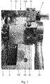
- Fig. 2 is a perspective view of a part of the driving mechanism of the railway welding machine of Fig. 1 .
- Fig. 3 is another perspective view of a part of the driving mechanism of the railway welding machine of Fig. 1 .
- Fig. 4 is an exploded view of the upper transmission mechanism and the upper shaft of the driving mechanism of Fig. 2 .
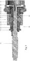
- Fig. 5 is a cross-section view of a part of the upper transmission mechanism and the upper shaft of Fig. 4 .
- Fig. 6 is a perspective view of a part of the driving mechanism used in the railway welding machine of Fig. 2 (without the first chain) and shows the decoupling of the male coupling device and the female coupling device.
- Fig. 1 is a perspective view of a part of the driving mechanism of the railway welding machine of Fig. 1 .
- Fig. 3 is another perspective view of a part of the driving mechanism of the railway welding machine of Fig. 1 .
- Fig. 4 is an exploded view of the upper transmission
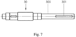
- FIG. 7 is a perspective view of the upper shaft in accordance with the preferred embodiment of the present invention.
- Fig. 8 is a cross-section view of the shaft keyway bush in accordance with the preferred embodiment of the present invention.
- Fig. 9 is a cross-section view taken along the line A-A of the shaft keyway bush of Fig. 8 in accordance with the preferred embodiment of the present invention.
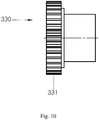
- Fig. 10 is a cross-section view of the male bush in accordance with the preferred embodiment of the present invention.
- the driving mechanism 1 includes a motor 2, an upper transmission mechanism 3, a first lower transmission mechanism 5, a second lower transmission mechanism 8, a first chain 6, a second chain 9, a first roller 4, and a second roller 7.
- the motor 2, the upper transmission mechanism 3, the first lower transmission mechanism 5, and the second lower transmission mechanism 8 are connected to a body case 100 of the railway welding machine 10.
- the driving mechanism 1 includes the motor 2 (connected to the upper shaft 30 and partially shown in the drawings), the upper transmission mechanism 3, and the first chain 6 of the driving mechanism 1.
- the motor 2 is disposed on the body case 100 of the railway welding machine 10 and produces a force to drive the upper transmission mechanism 3.
- the upper transmission mechanism 3 connected to the motor 2 includes an upper shaft 30 and a coupling mechanism 31.
- the motor 2 is connected to one end of the upper shaft 30 and drives the upper shaft 30.
- the upper shaft 30 passes through the coupling mechanism 31, including a shaft key seat 30 and a shaft key 303.
- the shaft key seat 30 is located at the outer section 305 of the upper shaft 30 which is distanced from the motor 2, as shown in Fig. 7 .
- the shaft key 303 may be partially disposed in the shaft key seat 30, while partially protruding out of the shaft key seat 30 for engaging the coupling mechanism 31.
- the coupling mechanism 31 includes a female coupling device 32 and a male coupling device 33.
- the upper shaft 30 passes through the coupling mechanism 31.
- the body case 100 of the railway welding machine 10 provides a protective cover 102 to cover the driving mechanism 1, so the protective cover 102 can prevent the coupling mechanism 31 from dust and pollution and prevent a welding worker from contacting the driving mechanism 1.
- the female coupling device 32 includes a female bush 320, a sprocket assembly 322, and a shaft bush 325.
- the female bush 320 is configured to be hollow and is provided with teeth 321 therein for engaging the male coupling device 33 and for engaging the sprocket assembly 322. Namely, one end of the female bush 320 connects to the sprocket assembly 322, and the other end of the female bush 320 connects to the male coupling device 33.
- the sprocket assembly 322 may include a sprocket 323 for engaging the first chain 6 and a sprocket sleeve 324 for engaging the female bush 320.
- the sprocket sleeve 324 connects to the female bush 320 and holds the sprocket 323. Therefore, when the female bush 320 is driven, the sprocket assembly 322 is driven accordingly.
- the shaft bush 325 is a cylindrical lining designed to allow independent movement between the female coupling device 32 and the upper shaft 30. Specifically, the upper shaft 30 passes through the shaft bush 325, while a shaft bush 325 passing through the female bush 320 and the sprocket assembly 322 and disposed around the upper shaft 30.
- the shaft bush 325 may prevent the upper shaft 30 from rotating the female bush 320 and the sprocket assembly 322 or allow independent movement between the upper shaft 30 and the female coupling device 32 (such as the female bush 320 and the sprocket assembly 322). When the upper shaft 30 rotates, it does not directly rotate the female coupling device 32.
- the male coupling device 33 includes a shaft keyway 333 configured to receive and be engaged with the shaft key 303 of the upper shaft 30.
- the male coupling device 33 includes a male bush 330 and a shaft keyway bush 332.
- the shaft keyway bush 332 connects to the male bush 330 and lies between the male bush 330 and the upper shaft 30.
- the shaft keyway 333 of the shaft keyway bush 332 engages the shaft key 303 of the upper shaft 30.
- Fig. 8 shows the shaft keyway 333 for receiving the shaft key 303. Therefore, the engagement of the upper shaft 30 and the male coupling device 33 allows the upper shaft 30 to rotate the male coupling device 33.
- the upper shaft 30 drives the male coupling device 33 by the shaft key 303.
- a welding worker needs to couple the male coupling device 33 to the female coupling device 32.
- the male bush 330 is configured to be hollow and is provided with protruding teeth 331 for engaging the teeth 321 of the female bush 320.
- the male coupling device 33 transmits the force to the female coupling device 32.
- Fig. 6 shows that the male coupling device 33 is decoupled from the female coupling device 32.
- the male coupling device 33 does not transmit the force to the female coupling device 32 even though the upper shaft 30 may still rotate the male bush 330 of the male coupling device 33.
- a welding worker can move the railway welding machine 10 along the railway track T from one site to another site by his or her hands and rollers can be rotated freely and independently from the force of the motor 2 or from the resistance of the motor 2.
- the female bush 320 is made of plastic and the male bush 330 is made of metal.
- the plastic materials of the female bush 320 have a wear-resistant effect.
- a retaining washer 334 and a screw 335 are fixed to the male coupling device 33 to prevent the male coupling device 33 from slipping out of the upper transmission mechanism 3.
- the upper transmission mechanism 3 is further provided with a threaded bolt 336, a retaining washer 334', a retaining washer 334", and a shaft key collar 337 to reinforce the connection and operation of the upper transmission mechanism 3. Based on the above arrangement of the upper transmission mechanism 3 and the upper shaft 30, the coupling mechanism 31 can be replaced smoothly, is not worn out easily during operation, and is easily and smoothly coupled.
- the upper transmission mechanism 3 may further include an operating mechanism 34, so a welding worker may easily move the teeth 331 of the male coupling device 33 out of or into the teeth 321 of the female coupling device 32.
- the operating mechanism 34 is connected to the outer end of the male coupling device 33.
- the operating mechanism 34 includes a holder 35, a handle 36, a reinforcement collar 37, and a reinforcement collar bush 38.
- the holder 35 extends from the railway welding machine 10 in parallel to the upper shaft 30 to support and controls the male coupling device 33.
- a pivot axis P is provided at the end of the holder 35.
- the handle 36 is pivotably connected to the holder 35 relative to the pivot axis P and connected to the male coupling device 33.
- Fig. 10 is a cross-section view of the male bush which can also be a connecting hub in accordance with the preferred embodiment of the present invention.
- the reinforcement collar bush 38 is attached to the male bush 330 of the male coupling device 33 and is disposed between the male coupling device 33 and the reinforcement collar 37.
- the reinforcement collar bush 38 allows independent movement between the male coupling device 33 and the operating mechanism 34 (such as the holder 35, the handle 36, and the reinforcement collar 37). Therefore, the operating mechanism 34 allows a welding worker to safely control and operate the driving mechanism 1.
- Fig. 11 is a perspective view of a part of the first lower transmission mechanism of the driving mechanism of Fig. 1 .
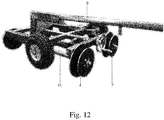
- Fig. 12 is a perspective view of the first roller and the second roller of a part of the driving mechanism of Fig. 1 .
- the driving mechanism 1 includes the first roller 4, the first lower transmission mechanism 5, and the first chain 6.
- the first lower transmission mechanism 5 includes a first lower shaft 51 disposed in parallel to the upper shaft 30, locating below the upper transmission mechanism 3.
- the first lower shaft 51 is a driven shaft while the upper shaft 30 is a driving shaft.
- One end of the first lower shaft 51 connects to the first roller 4 which is used for rolling along the railway track T.
- the other end of the first lower shaft 51 connects to the case body of the railway welding machine 10.
- the other end of the first lower shaft 51 connects to another roller.
- the first chain 6 is provided therebetween.
- the first lower shaft 51 has a first sprocket 511.
- the first chain 6 engages the sprocket 323 of the upper transmission mechanism 3 and engages the first sprocket 511 of the first lower shaft 51 of the first lower transmission mechanism 5, transmitting the force from the upper shaft 30 to the first lower shaft 51.
- the male coupling device 33 is coupled to the female coupling device 32
- the first chain 6 drives and transmits the force from the upper transmission mechanism 3 to the first lower transmission mechanism 5.
- the first chain 6 rotates the first lower shaft 51 to drive the first roller 4, and the railway welding machine 10 can drive on the railway track T to feed welding materials.
- the driving mechanism 1 may contain a second lower transmission mechanism 8, a second roller 7, and a second chain 9.
- the second roller 7 is also used for rolling along the railway track T.
- the second lower transmission mechanism 8 includes a second lower shaft connected to the second roller 7.
- the second lower shaft is disposed in parallel to the upper shaft 30 and the first lower shaft 51 and in the same plane of the first lower transmission mechanism 5.
- the second lower shaft includes a sprocket (not shown in the drawings) and the first lower shaft 51 further includes a second sprocket 513.
- the second lower shaft is a driven shaft. One end of the second lower shaft connects to the second roller 7, while the other end of the second lower shaft connects to the body case 100 of the railway welding machine 10.
- the other end of the second lower shaft connects to another roller.
- the second chain 9 engages the second sprocket 513 of the first lower shaft 51 of the first lower transmission mechanism 5 and the sprocket of the second lower shaft (not shown in the drawings) of the second lower transmission mechanism 8 and transmits in the direction of the railway track T.
- the male coupling device 33 is coupled to the female coupling device 32
- the second chain 9 transmits the force from the first lower transmission mechanism 5 to the second lower transmission mechanism 8 and rotates the second lower shaft to drive the second roller 7.
- the force produced by the motor 2 may be transmitted in the following sequence: (1) the force rotates the upper shaft 30, (2) the upper shaft 30 transmits the force to the male coupling device 33 via the engagement of the shaft key 303 of the upper shaft 30 and the shaft keyway 333 of the male coupling device 33, (3) the male coupling device 33 transmits the force to the female coupling device 32 via the coupling of the teeth 331 of the male coupling device 33 and the teeth 321 of the female coupling device 32, (4) the sprocket assembly 322 of the female coupling device 32 transmits the force to the first chain 6, (5) the first chain 6 transmits the force to the first lower shaft 51, (6) the first lower shaft 51 transmits the force to the first roller 4 and to the second chain 9, (7) the second chain 9 transmits the force to the second lower shaft, and (8) the second lower shaft transmits the force to the second roller 7.
- a welding worker may easily operate the railway welding machine 10 on the railway track T
Landscapes
- Engineering & Computer Science (AREA)
- General Engineering & Computer Science (AREA)
- Mechanical Engineering (AREA)
- Butt Welding And Welding Of Specific Article (AREA)
Abstract
Description
- The present invention relates to a driving mechanism used in a railway welding machine that operates along a railway track, more particularly a coupling mechanism.
- The repair of a railway track is important for public transportation construction. To secure the safety of passengers or goods, the railway track needs to be repaired and maintained on a regular basis. If a part of the railway track has a defect, a welding worker needs to cut off the defected part and rectify the railway track by welding, e.g., cladding. A railway welding machine with rollers can evenly distribute welding materials on the railway track. However, a conventional railway welding machine has several disadvantages. For example, a conventional coupling mechanism for transmitting the force from the motor to the roller is not well structured in a conventional railway welding machine. The components of the driving mechanism cannot be easily and smoothly operated and are easily worn out. Therefore, the conventional driving mechanism of a railway welding machine needs to be frequently substituted and costs much time and money. Therefore, it is important to provide a driving mechanism used in a railway welding machine that operates along a railway track, and more particularly a coupling mechanism that can be replaced smoothly, is not worn out easily during operation, and is easily and smoothly coupled.
- The objective of the present invention is to provide a driving mechanism used in a railway welding machine that operates along a railway track, and more particularly a coupling mechanism that can be replaced smoothly, is not worn out easily during operation, and is easily and smoothly coupled.
- The following summarizes some aspects of the present invention to provide a basic understanding of the technology discussed. This summary is not an extensive overview of all contemplated features of the invention, and is intended neither to identify key or critical elements of all aspects of the invention nor to delineate the scope of any or all aspects of the invention. Its sole purpose is to present some concepts of one or more aspects of the invention in a summary form as a prelude to the more detailed description that is presented later.
- A first aspect of the present invention provides a driving mechanism used in a railway welding machine that operates along a railway track, comprising: a motor producing a force, and an upper transmission mechanism connected to the motor, including: an upper shaft driven by the motor and including: a shaft key seat, and a shaft key disposed in the shaft key seat, and a coupling mechanism, wherein the upper shaft passes through the coupling mechanism including: a female coupling device, and a male coupling device detachably coupled to the female coupling device, the male coupling device including a shaft keyway configured to receive and be engaged with the shaft key of the upper shaft so that the upper shaft rotates the male coupling device, wherein when the male coupling device is coupled to the female coupling device, the male coupling device transmits the force to the female coupling device, and when the male coupling device is decoupled from the female coupling device, the male coupling device does not transmit the force to the female coupling device.
- In a second aspect of the present invention according to the first aspect, the male coupling device further includes: a male bush configured to be hollow and provided with teeth therein, and a shaft keyway bush connecting to the male bush and disposed between the male bush and the upper shaft, the shaft keyway bush provided with the shaft keyway configured to receive the shaft key of the upper shaft.
- In a third aspect of the present invention according to the second aspect, the female coupling device further includes: a female bush configured to be hollow and provided with teeth for engaging the teeth of the male bush, so that when the teeth of the male bush are coupled to the teeth of the female bush, the male coupling device transmits the force to the female coupling device, a sprocket assembly connected to the female bush and provided with a sprocket, and a shaft bush passing through the female bush and the sprocket assembly and disposed around the upper shaft in order to allow independent movement between the upper shaft and the female coupling device.
- In a fourth aspect of the present invention according to the third aspect, the sprocket assembly includes a sprocket sleeve for engaging the female bush and holding the sprocket of the sprocket assembly.
- In a fifth aspect of the present invention according to any one of the first to fourth aspects, the upper transmission mechanism further includes an operating mechanism connected to the male coupling device, and the operating mechanism includes: a holder extending from the railway welding machine in parallel to the upper shaft, a handle connected to the male coupling device and pivotably connected to the holder, a reinforcement collar flexibly attached to the handle and the male coupling device for facilitating the coupling between the male coupling device and the female coupling device, and a reinforcement collar bush attached to the male coupling device and disposed between the male coupling device and the reinforcement collar in order to allow independent movement between the male coupling device and the operating mechanism.
- In a sixth aspect of the present invention according to the fifth aspect, the operating mechanism includes a retaining washer and a screw fixed to the male coupling device to prevent the male coupling device from slipping out of the upper transmission mechanism.
- In a seventh aspect of the present invention according to any one of the first to sixth aspects, the driving mechanism further comprises: a first roller rolling along the railway track, a first lower transmission mechanism including a first lower shaft disposed in parallel to the upper shaft, the first lower shaft connected to the first roller and including a first sprocket, and a first chain engaging the sprocket of the sprocket assembly of the female coupling device of the upper transmission mechanism and engaging the first sprocket of the first lower shaft of the first lower transmission mechanism, wherein when the male coupling device is coupled to the female coupling device, the first chain transmits the force from the upper transmission mechanism to the first lower transmission mechanism and rotates the first lower shaft to drive the first roller.
- In an eighth aspect of the present invention according to the seventh aspect, the driving mechanism further comprises: a second roller rolling along the railway track, a second lower transmission mechanism including a second lower shaft connected to the second roller, the second lower shaft disposed in parallel to the upper shaft and the first lower shaft and in the same plane of the first lower transmission mechanism, the second lower shaft including a sprocket, the first lower shaft including a second sprocket, and a second chain engaging the second sprocket of the first lower shaft of the first lower transmission mechanism and the sprocket of the second lower shaft of the second lower transmission mechanism and transmits in the direction of the railway track, wherein when the male coupling device is coupled to the female coupling device, the second chain transmits the force from the first lower transmission mechanism to the second lower transmission mechanism and rotates the second lower shaft to drive the second roller.
- In a ninth aspect of the present invention according to the eighth aspect, the motor, the upper transmission mechanism, the first lower transmission mechanism, and the second lower transmission mechanism are connected to a body case of the railway welding machine, and the body case provides the coupling mechanism with a protective cover.
- In a tenth aspect of the present invention according to the third or fourth aspect, the female bush is made of plastic and the male bush is made of metal.
- Advantageously, the coupling mechanism of the driving mechanism can be replaced smoothly, is not worn out easily during operation, and is easily and smoothly coupled.
- Further benefits and advantages of the present invention will become apparent after a careful reading of the detailed description with appropriate reference to the accompanying drawings.
-
-
Fig. 1 is a perspective view of a railway welding machine that operates along a railway track in accordance with the preferred embodiment of the present invention. -
Fig. 2 is a perspective view of a part of the driving mechanism of the railway welding machine ofFig. 1 . -
Fig. 3 is another perspective view of a part of the driving mechanism of the railway welding machine ofFig. 1 . -
Fig. 4 is an exploded view of the upper transmission mechanism and the upper shaft of the driving mechanism ofFig. 2 . -
Fig. 5 is a cross-section view of a part of the upper transmission mechanism and the upper shaft of the driving mechanism ofFig. 4 . -
Fig. 6 is a perspective view of a part of the driving mechanism used in the railway welding machine ofFig. 2 (without the first chain) and shows the decoupling of the male coupling device and the female coupling device. -
Fig. 7 is a perspective view of the upper shaft in accordance with the preferred embodiment of the present invention. -
Fig. 8 is a cross-section view of the shaft keyway bush in accordance with the preferred embodiment of the present invention. -
Fig. 9 is a cross-section view taken along the line A-A of the shaft keyway bush ofFig. 8 in accordance with the preferred embodiment of the present invention. -
Fig. 10 is a cross-section view of the male bush in accordance with the preferred embodiment of the present invention. -
Fig. 11 is a perspective view of a part of the first lower transmission mechanism of the driving mechanism ofFig. 1 . -
Fig. 12 is a perspective view of the first roller and the second roller of a part of the driving mechanism ofFig. 1 . -
Fig. 1 is a perspective view of a railway welding machine that operates along a railway track in accordance with the preferred embodiment of the present invention. Therailway welding machine 10 operates on the railway track T through rollers to repair and maintain the railway track T. Therailway welding machine 10 includes abody case 100, amonitoring operator 104, awelding material provider 106, and adriving mechanism 1. Themonitoring operator 104 activates therailway welding machine 10 and controls thewelding material provider 106. Thedriving mechanism 1 is used in therailway welding machine 10 and is disposed on thebody case 100 of therailway welding machine 10, allowing therailway welding machine 10 to drive on the railway track T. Therefore, thewelding material provider 106 may continuously feed welding materials along the railway track T. -
Fig. 2 is a perspective view of a part of the driving mechanism of the railway welding machine ofFig. 1 .Fig. 3 is another perspective view of a part of the driving mechanism of the railway welding machine ofFig. 1 .Fig. 4 is an exploded view of the upper transmission mechanism and the upper shaft of the driving mechanism ofFig. 2 .Fig. 5 is a cross-section view of a part of the upper transmission mechanism and the upper shaft ofFig. 4 .Fig. 6 is a perspective view of a part of the driving mechanism used in the railway welding machine ofFig. 2 (without the first chain) and shows the decoupling of the male coupling device and the female coupling device.Fig. 7 is a perspective view of the upper shaft in accordance with the preferred embodiment of the present invention.Fig. 8 is a cross-section view of the shaft keyway bush in accordance with the preferred embodiment of the present invention.Fig. 9 is a cross-section view taken along the line A-A of the shaft keyway bush ofFig. 8 in accordance with the preferred embodiment of the present invention.Fig. 10 is a cross-section view of the male bush in accordance with the preferred embodiment of the present invention. - Please refer to
Figs. 1-10 together. Thedriving mechanism 1 includes amotor 2, anupper transmission mechanism 3, a firstlower transmission mechanism 5, a secondlower transmission mechanism 8, afirst chain 6, asecond chain 9, afirst roller 4, and a second roller 7. Themotor 2, theupper transmission mechanism 3, the firstlower transmission mechanism 5, and the secondlower transmission mechanism 8 are connected to abody case 100 of therailway welding machine 10. - In
Fig. 2 , thedriving mechanism 1 includes the motor 2 (connected to theupper shaft 30 and partially shown in the drawings), theupper transmission mechanism 3, and thefirst chain 6 of thedriving mechanism 1. Themotor 2 is disposed on thebody case 100 of therailway welding machine 10 and produces a force to drive theupper transmission mechanism 3. Theupper transmission mechanism 3 connected to themotor 2 includes anupper shaft 30 and acoupling mechanism 31. Themotor 2 is connected to one end of theupper shaft 30 and drives theupper shaft 30. Theupper shaft 30 passes through thecoupling mechanism 31, including a shaftkey seat 30 and ashaft key 303. The shaftkey seat 30 is located at theouter section 305 of theupper shaft 30 which is distanced from themotor 2, as shown inFig. 7 . Theshaft key 303 may be partially disposed in the shaftkey seat 30, while partially protruding out of the shaftkey seat 30 for engaging thecoupling mechanism 31. - In
Figs. 4 and5 , thecoupling mechanism 31 includes afemale coupling device 32 and amale coupling device 33. Theupper shaft 30 passes through thecoupling mechanism 31. InFig. 3 , thebody case 100 of therailway welding machine 10 provides aprotective cover 102 to cover thedriving mechanism 1, so theprotective cover 102 can prevent thecoupling mechanism 31 from dust and pollution and prevent a welding worker from contacting thedriving mechanism 1. - The
female coupling device 32 includes afemale bush 320, asprocket assembly 322, and ashaft bush 325. Thefemale bush 320 is configured to be hollow and is provided withteeth 321 therein for engaging themale coupling device 33 and for engaging thesprocket assembly 322. Namely, one end of thefemale bush 320 connects to thesprocket assembly 322, and the other end of thefemale bush 320 connects to themale coupling device 33. Thesprocket assembly 322 may include asprocket 323 for engaging thefirst chain 6 and asprocket sleeve 324 for engaging thefemale bush 320. Thesprocket sleeve 324 connects to thefemale bush 320 and holds thesprocket 323. Therefore, when thefemale bush 320 is driven, thesprocket assembly 322 is driven accordingly. Theshaft bush 325 is a cylindrical lining designed to allow independent movement between thefemale coupling device 32 and theupper shaft 30. Specifically, theupper shaft 30 passes through theshaft bush 325, while ashaft bush 325 passing through thefemale bush 320 and thesprocket assembly 322 and disposed around theupper shaft 30. Therefore, theshaft bush 325 may prevent theupper shaft 30 from rotating thefemale bush 320 and thesprocket assembly 322 or allow independent movement between theupper shaft 30 and the female coupling device 32 (such as thefemale bush 320 and the sprocket assembly 322). When theupper shaft 30 rotates, it does not directly rotate thefemale coupling device 32. - In order to transmit the force from the
upper shaft 30 to themale coupling device 33, themale coupling device 33 includes ashaft keyway 333 configured to receive and be engaged with theshaft key 303 of theupper shaft 30. In a preferred embodiment, themale coupling device 33 includes amale bush 330 and ashaft keyway bush 332. Theshaft keyway bush 332 connects to themale bush 330 and lies between themale bush 330 and theupper shaft 30. Theshaft keyway 333 of theshaft keyway bush 332 engages theshaft key 303 of theupper shaft 30.Fig. 8 shows theshaft keyway 333 for receiving theshaft key 303. Therefore, the engagement of theupper shaft 30 and themale coupling device 33 allows theupper shaft 30 to rotate themale coupling device 33. - The
upper shaft 30 drives themale coupling device 33 by theshaft key 303. However, to drive thefemale coupling device 32, a welding worker needs to couple themale coupling device 33 to thefemale coupling device 32. Specifically, in order to transmit the force from themale coupling device 33 to thefemale coupling device 32, themale bush 330 is configured to be hollow and is provided with protrudingteeth 331 for engaging theteeth 321 of thefemale bush 320. When theteeth 331 of themale bush 330 are coupled to theteeth 321 of thefemale bush 320, themale coupling device 33 transmits the force to thefemale coupling device 32. In contrast,Fig. 6 shows that themale coupling device 33 is decoupled from thefemale coupling device 32. When theteeth 331 of themale bush 330 are decoupled from theteeth 321 of thefemale bush 320, themale coupling device 33 does not transmit the force to thefemale coupling device 32 even though theupper shaft 30 may still rotate themale bush 330 of themale coupling device 33. In another embodiment, when theteeth 331 of themale bush 330 are decoupled from theteeth 321 of thefemale bush 320, a welding worker can move therailway welding machine 10 along the railway track T from one site to another site by his or her hands and rollers can be rotated freely and independently from the force of themotor 2 or from the resistance of themotor 2. In a preferred embodiment, thefemale bush 320 is made of plastic and themale bush 330 is made of metal. The plastic materials of thefemale bush 320 have a wear-resistant effect. A retainingwasher 334 and ascrew 335 are fixed to themale coupling device 33 to prevent themale coupling device 33 from slipping out of theupper transmission mechanism 3. In a preferred embodiment, theupper transmission mechanism 3 is further provided with a threadedbolt 336, a retaining washer 334', a retainingwasher 334", and a shaftkey collar 337 to reinforce the connection and operation of theupper transmission mechanism 3. Based on the above arrangement of theupper transmission mechanism 3 and theupper shaft 30, thecoupling mechanism 31 can be replaced smoothly, is not worn out easily during operation, and is easily and smoothly coupled. - In a preferred embodiment, the
upper transmission mechanism 3 may further include anoperating mechanism 34, so a welding worker may easily move theteeth 331 of themale coupling device 33 out of or into theteeth 321 of thefemale coupling device 32. Theoperating mechanism 34 is connected to the outer end of themale coupling device 33. Specifically, theoperating mechanism 34 includes aholder 35, ahandle 36, areinforcement collar 37, and areinforcement collar bush 38. Theholder 35 extends from therailway welding machine 10 in parallel to theupper shaft 30 to support and controls themale coupling device 33. A pivot axis P is provided at the end of theholder 35. Thehandle 36 is pivotably connected to theholder 35 relative to the pivot axis P and connected to themale coupling device 33. Thereinforcement collar 37 flexibly attached to thehandle 36 and themale coupling device 33 for facilitating the coupling between themale coupling device 33 and thefemale coupling device 32. Thereinforcement collar 37 advantageously reinforces the attachment of thehandle 36 and themale coupling device 33. In addition,Fig. 10 is a cross-section view of the male bush which can also be a connecting hub in accordance with the preferred embodiment of the present invention. Thereinforcement collar bush 38 is attached to themale bush 330 of themale coupling device 33 and is disposed between themale coupling device 33 and thereinforcement collar 37. Thereinforcement collar bush 38 allows independent movement between themale coupling device 33 and the operating mechanism 34 (such as theholder 35, thehandle 36, and the reinforcement collar 37). Therefore, theoperating mechanism 34 allows a welding worker to safely control and operate thedriving mechanism 1. -
Fig. 11 is a perspective view of a part of the first lower transmission mechanism of the driving mechanism ofFig. 1 .Fig. 12 is a perspective view of the first roller and the second roller of a part of the driving mechanism ofFig. 1 . Please refer toFigs. 1-12 together. Thedriving mechanism 1 includes thefirst roller 4, the firstlower transmission mechanism 5, and thefirst chain 6. The firstlower transmission mechanism 5 includes a firstlower shaft 51 disposed in parallel to theupper shaft 30, locating below theupper transmission mechanism 3. The firstlower shaft 51 is a driven shaft while theupper shaft 30 is a driving shaft. One end of the firstlower shaft 51 connects to thefirst roller 4 which is used for rolling along the railway track T. The other end of the firstlower shaft 51 connects to the case body of therailway welding machine 10. In another embodiment, the other end of the firstlower shaft 51 connects to another roller. - To transmit the force from the
upper transmission mechanism 3 to the firstlower transmission mechanism 5, thefirst chain 6 is provided therebetween. Specifically, the firstlower shaft 51 has afirst sprocket 511. Thefirst chain 6 engages thesprocket 323 of theupper transmission mechanism 3 and engages thefirst sprocket 511 of the firstlower shaft 51 of the firstlower transmission mechanism 5, transmitting the force from theupper shaft 30 to the firstlower shaft 51. When themale coupling device 33 is coupled to thefemale coupling device 32, thefirst chain 6 drives and transmits the force from theupper transmission mechanism 3 to the firstlower transmission mechanism 5. Accordingly, thefirst chain 6 rotates the firstlower shaft 51 to drive thefirst roller 4, and therailway welding machine 10 can drive on the railway track T to feed welding materials. - Similarly, the
driving mechanism 1 may contain a secondlower transmission mechanism 8, a second roller 7, and asecond chain 9. The second roller 7 is also used for rolling along the railway track T. Specifically, the secondlower transmission mechanism 8 includes a second lower shaft connected to the second roller 7. The second lower shaft is disposed in parallel to theupper shaft 30 and the firstlower shaft 51 and in the same plane of the firstlower transmission mechanism 5. To transmit thesecond chain 9, the second lower shaft includes a sprocket (not shown in the drawings) and the firstlower shaft 51 further includes asecond sprocket 513. The second lower shaft is a driven shaft. One end of the second lower shaft connects to the second roller 7, while the other end of the second lower shaft connects to thebody case 100 of therailway welding machine 10. In another embodiment, the other end of the second lower shaft connects to another roller. Thesecond chain 9 engages thesecond sprocket 513 of the firstlower shaft 51 of the firstlower transmission mechanism 5 and the sprocket of the second lower shaft (not shown in the drawings) of the secondlower transmission mechanism 8 and transmits in the direction of the railway track T. When themale coupling device 33 is coupled to thefemale coupling device 32, thesecond chain 9 transmits the force from the firstlower transmission mechanism 5 to the secondlower transmission mechanism 8 and rotates the second lower shaft to drive the second roller 7. - In sum, when the
male coupling device 33 is coupled to thefemale coupling device 32, the force produced by themotor 2 may be transmitted in the following sequence: (1) the force rotates theupper shaft 30, (2) theupper shaft 30 transmits the force to themale coupling device 33 via the engagement of theshaft key 303 of theupper shaft 30 and theshaft keyway 333 of themale coupling device 33, (3) themale coupling device 33 transmits the force to thefemale coupling device 32 via the coupling of theteeth 331 of themale coupling device 33 and theteeth 321 of thefemale coupling device 32, (4) thesprocket assembly 322 of thefemale coupling device 32 transmits the force to thefirst chain 6, (5) thefirst chain 6 transmits the force to the firstlower shaft 51, (6) the firstlower shaft 51 transmits the force to thefirst roller 4 and to thesecond chain 9, (7) thesecond chain 9 transmits the force to the second lower shaft, and (8) the second lower shaft transmits the force to the second roller 7. In this way, a welding worker may easily operate therailway welding machine 10 on the railway track T by controlling thedriving mechanism 1 of therailway welding machine 10. - Although the invention has been explained in relation to its preferred embodiment(s) as mentioned above, it is to be understood that many other possible modifications and variations can be made without departing from the scope of the present invention. It is, therefore, contemplated that the appended claim or claims will cover such modifications and variations that fall within the true scope of the invention.
-
T railway track 10 railway welding machine 100 body case 102 protective cover 104 monitoring operator 106 welding material provider 1 driving mechanism 2 motor 3 upper transmission mechanism 30 upper shaft 301 shaft key seat 303 shaft key 305 outer section 31 coupling mechanism 32 female coupling device 320 female bush 321 teeth 322 sprocket assembly 323 sprocket 324 sprocket sleeve 325 shaft bush 33 male coupling device 330 male bush 331 teeth 332 shaft keyway bush 333 shaft keyway 334, 334', 334" retaining washer 335 screw 336 threaded bolt 337 shaft key collar 34 operating mechanism 35 holder 36 handle 37 reinforcement collar 38 reinforcement collar bush 4 first roller 5 first lower transmission mechanism 51 first lower shaft 511 first sprocket 513 second sprocket 6 first chain 7 second roller 8 second lower transmission mechanism 9 second chain P pivot axis
Claims (10)
- A driving mechanism used in a railway welding machine that operates along a railway track, comprising:a motor (2) producing a force, andan upper transmission mechanism (3) connected to the motor (2), including:an upper shaft (30) driven by the motor (2) and including:a shaft key seat (301), anda shaft key (303) disposed in the shaft key seat (301), anda coupling mechanism (31), wherein the upper shaft (30) passes through the coupling mechanism (31) including:a female coupling device (32), anda male coupling device (33) detachably coupled to the female coupling device (32), the male coupling device (33) including a shaft keyway (333) configured to receive and be engaged with the shaft key (303) of the upper shaft (30) so that the upper shaft (30) rotates the male coupling device (33),wherein when the male coupling device (33) is coupled to the female coupling device (32), the male coupling device (33) transmits the force to the female coupling device (32), and when the male coupling device (33) is decoupled from the female coupling device (32), the male coupling device (33) does not transmit the force to the female coupling device (32).
- The driving mechanism of Claim 1, wherein the male coupling device (33) further includes:a male bush (330) configured to be hollow and provided with teeth (331) therein, anda shaft keyway bush (332) connecting to the male bush (330) and disposed between the male bush (330) and the upper shaft (30), the shaft keyway bush (332) provided with the shaft keyway (333) configured to receive the shaft key (303) of the upper shaft (30).
- The driving mechanism of Claim 2, wherein the female coupling device (32) further includes:a female bush (320) configured to be hollow and provided with teeth (321) for engaging the teeth (331) of the male bush (330), so that when the teeth (331) of the male bush (330) are coupled to the teeth (321) of the female bush (320), the male coupling device (33) transmits the force to the female coupling device (32),a sprocket assembly (322) connected to the female bush (320) and provided with a sprocket (323), anda shaft bush (325) passing through the female bush (320) and the sprocket assembly (322) and disposed around the upper shaft (30) in order to allow independent movement between the upper shaft (30) and the female coupling device (32).
- The driving mechanism of Claim 3, wherein the sprocket assembly (322) includes a sprocket sleeve (324) for engaging the female bush (320) and holding the sprocket (323) of the sprocket assembly (322).
- The driving mechanism of any one of Claims 1-4, wherein the upper transmission mechanism (3) further includes an operating mechanism (34) connected to the male coupling device (33), and the operating mechanism (34) includes:a holder (35) extending from the railway welding machine (10) in parallel to the upper shaft (30),a handle (36) connected to the male coupling device (33) and pivotably connected to the holder (35),a reinforcement collar (37) flexibly attached to the handle (36) and the male coupling device (33) for facilitating the coupling between the male coupling device (33) and the female coupling device (32), anda reinforcement collar bush (38) attached to the male coupling device (33) and disposed between the male coupling device (33) and the reinforcement collar (37) in order to allow independent movement between the male coupling device (33) and the operating mechanism (34).
- The driving mechanism of Claim 5, wherein the operating mechanism (34) includes a retaining washer (334) and a screw (335) fixed to the male coupling device (33) to prevent the male coupling device (33) from slipping out of the upper transmission mechanism (3).
- The driving mechanism of any one of Claims 1-6, further comprising:a first roller (4) rolling along the railway track (T),a first lower transmission mechanism (5) including a first lower shaft (51) disposed in parallel to the upper shaft (30), the first lower shaft (51) connected to the first roller (4) and including a first sprocket (511), anda first chain (6) engaging the sprocket (323) of the sprocket assembly (322) of the female coupling device (32) of the upper transmission mechanism (3) and engaging the first sprocket (511) of the first lower shaft (51) of the first lower transmission mechanism (5),wherein when the male coupling device (33) is coupled to the female coupling device (32), the first chain (6) transmits the force from the upper transmission mechanism (3) to the first lower transmission mechanism (5) and rotates the first lower shaft (51) to drive the first roller (4).
- The driving mechanism of Claim 7, further comprising:a second roller (7) rolling along the railway track (T),a second lower transmission mechanism (8) including a second lower shaft connected to the second roller (7), the second lower shaft disposed in parallel to the upper shaft (30) and the first lower shaft (51) and in the same plane of the first lower transmission mechanism (5), the second lower shaft including a sprocket, the first lower shaft (51) including a second sprocket (513), anda second chain (9) engaging the second sprocket (513) of the first lower shaft (51) of the first lower transmission mechanism (5) and the sprocket of the second lower shaft of the second lower transmission mechanism (8) and transmits in the direction of the railway track (T),wherein when the male coupling device (33) is coupled to the female coupling device (32), the second chain (9) transmits the force from the first lower transmission mechanism (5) to the second lower transmission mechanism (8) and rotates the second lower shaft to drive the second roller (7).
- The driving mechanism of Claim 8, wherein the motor (2), the upper transmission mechanism (3), the first lower transmission mechanism (5), and the second lower transmission mechanism (8) are connected to a body case (100) of the railway welding machine (10), and the body case (100) provides the coupling mechanism (31) with a protective cover (102).
- The driving mechanism of Claim 3 or 4, wherein the female bush (320) is made of plastic and the male bush (330) is made of metal.
Priority Applications (1)
| Application Number | Priority Date | Filing Date | Title |
|---|---|---|---|
| EP20169788.5A EP3896302B1 (en) | 2020-04-16 | 2020-04-16 | Driving mechanism used in a railway welding machine that operates along a railway track |
Applications Claiming Priority (1)
| Application Number | Priority Date | Filing Date | Title |
|---|---|---|---|
| EP20169788.5A EP3896302B1 (en) | 2020-04-16 | 2020-04-16 | Driving mechanism used in a railway welding machine that operates along a railway track |
Publications (2)
| Publication Number | Publication Date |
|---|---|
| EP3896302A1 true EP3896302A1 (en) | 2021-10-20 |
| EP3896302B1 EP3896302B1 (en) | 2023-01-11 |
Family
ID=70292828
Family Applications (1)
| Application Number | Title | Priority Date | Filing Date |
|---|---|---|---|
| EP20169788.5A Active EP3896302B1 (en) | 2020-04-16 | 2020-04-16 | Driving mechanism used in a railway welding machine that operates along a railway track |
Country Status (1)
| Country | Link |
|---|---|
| EP (1) | EP3896302B1 (en) |
Citations (3)
| Publication number | Priority date | Publication date | Assignee | Title |
|---|---|---|---|---|
| US4923558A (en) * | 1988-05-02 | 1990-05-08 | Pfaff Industriemaschinen, Gmbh | Device for the welding of plastic foil |
| US20150300413A1 (en) * | 2014-04-18 | 2015-10-22 | Jason Story | Drive shaft splint joint |
| EP3398754A1 (en) * | 2017-05-05 | 2018-11-07 | Leister Technologies AG | Drive assembly for welding machines |
-
2020
- 2020-04-16 EP EP20169788.5A patent/EP3896302B1/en active Active
Patent Citations (3)
| Publication number | Priority date | Publication date | Assignee | Title |
|---|---|---|---|---|
| US4923558A (en) * | 1988-05-02 | 1990-05-08 | Pfaff Industriemaschinen, Gmbh | Device for the welding of plastic foil |
| US20150300413A1 (en) * | 2014-04-18 | 2015-10-22 | Jason Story | Drive shaft splint joint |
| EP3398754A1 (en) * | 2017-05-05 | 2018-11-07 | Leister Technologies AG | Drive assembly for welding machines |
Also Published As
| Publication number | Publication date |
|---|---|
| EP3896302B1 (en) | 2023-01-11 |
Similar Documents
| Publication | Publication Date | Title |
|---|---|---|
| US6178643B1 (en) | Hand-held ratchet action tool | |
| US4947629A (en) | Mower | |
| US20070163412A1 (en) | Methods and apparatus for movable machining tools, including for wall saws | |
| US5934143A (en) | Armature shaft deflection limiter | |
| EP3896302A1 (en) | Driving mechanism used in a railway welding machine that operates along a railway track | |
| US20060048621A1 (en) | Rotary cutter and rotary cutting apparatus provided with the rotary cutter | |
| US20040003503A1 (en) | Modular hand-held power tool system | |
| US7165345B2 (en) | Automated control mechanism for a snow blower discharge chute | |
| US20050155471A1 (en) | Radial feed facing head for boring bar | |
| US4434689A (en) | Cutter head drive shaft for portable tube end preparation tool | |
| KR100607063B1 (en) | Cutting device using heavy equipment | |
| KR102731984B1 (en) | Tool automatic changer | |
| US10835962B2 (en) | Disengagement mechanism for boring bar apparatus | |
| US6578349B2 (en) | Pivoting gearbox for rotary mower | |
| JP2006502877A (en) | Tool heads, adjustment rings and cutting machines, especially scalpers | |
| CN109877248B (en) | Safe and reliable reinforcement bar straightening machine for civil construction | |
| US1346966A (en) | Coal-mining machine | |
| JP3083813U (en) | Point cleaning machine | |
| US20250289072A1 (en) | Band saw | |
| CN211006283U (en) | Milling drum driving system and milling machine | |
| EP1501652A1 (en) | Hand-held saber saw | |
| DE102022105722A1 (en) | WORK EQUIPMENT | |
| JP4181518B2 (en) | Trolley disassembly device for conveyor chain | |
| KR102262848B1 (en) | Wood shredder consisting of internal combustion engine, hydraulic motor and hydraulic pump | |
| US1011221A (en) | Channeling-machine. |
Legal Events
| Date | Code | Title | Description |
|---|---|---|---|
| PUAI | Public reference made under article 153(3) epc to a published international application that has entered the european phase |
Free format text: ORIGINAL CODE: 0009012 |
|
| STAA | Information on the status of an ep patent application or granted ep patent |
Free format text: STATUS: THE APPLICATION HAS BEEN PUBLISHED |
|
| AK | Designated contracting states |
Kind code of ref document: A1 Designated state(s): AL AT BE BG CH CY CZ DE DK EE ES FI FR GB GR HR HU IE IS IT LI LT LU LV MC MK MT NL NO PL PT RO RS SE SI SK SM TR |
|
| B565 | Issuance of search results under rule 164(2) epc |
Effective date: 20200921 |
|
| STAA | Information on the status of an ep patent application or granted ep patent |
Free format text: STATUS: REQUEST FOR EXAMINATION WAS MADE |
|
| 17P | Request for examination filed |
Effective date: 20220310 |
|
| RBV | Designated contracting states (corrected) |
Designated state(s): AL AT BE BG CH CY CZ DE DK EE ES FI FR GB GR HR HU IE IS IT LI LT LU LV MC MK MT NL NO PL PT RO RS SE SI SK SM TR |
|
| RIC1 | Information provided on ipc code assigned before grant |
Ipc: F16D 11/10 20060101ALI20220421BHEP Ipc: F16D 1/04 20060101AFI20220421BHEP |
|
| GRAP | Despatch of communication of intention to grant a patent |
Free format text: ORIGINAL CODE: EPIDOSNIGR1 |
|
| STAA | Information on the status of an ep patent application or granted ep patent |
Free format text: STATUS: GRANT OF PATENT IS INTENDED |
|
| GRAJ | Information related to disapproval of communication of intention to grant by the applicant or resumption of examination proceedings by the epo deleted |
Free format text: ORIGINAL CODE: EPIDOSDIGR1 |
|
| STAA | Information on the status of an ep patent application or granted ep patent |
Free format text: STATUS: REQUEST FOR EXAMINATION WAS MADE |
|
| INTG | Intention to grant announced |
Effective date: 20220617 |
|
| INTC | Intention to grant announced (deleted) | ||
| RIN1 | Information on inventor provided before grant (corrected) |
Inventor name: THE OTHER INVENTOR HAS WAIVED HIS RIGHT TO BE THUS MENTIONED. Inventor name: HOLTKAMP, STEFAN |
|
| GRAS | Grant fee paid |
Free format text: ORIGINAL CODE: EPIDOSNIGR3 |
|
| STAA | Information on the status of an ep patent application or granted ep patent |
Free format text: STATUS: GRANT OF PATENT IS INTENDED |
|
| GRAP | Despatch of communication of intention to grant a patent |
Free format text: ORIGINAL CODE: EPIDOSNIGR1 |
|
| INTG | Intention to grant announced |
Effective date: 20220831 |
|
| RIN1 | Information on inventor provided before grant (corrected) |
Inventor name: THE OTHER INVENTOR HAS WAIVED HIS RIGHT TO BE THUS MENTIONED. Inventor name: HOLTKAMP, STEFAN |
|
| GRAA | (expected) grant |
Free format text: ORIGINAL CODE: 0009210 |
|
| STAA | Information on the status of an ep patent application or granted ep patent |
Free format text: STATUS: THE PATENT HAS BEEN GRANTED |
|
| RIN1 | Information on inventor provided before grant (corrected) |
Inventor name: PRILL, FRANK Inventor name: HOLTKAMP, STEFAN |
|
| AK | Designated contracting states |
Kind code of ref document: B1 Designated state(s): AL AT BE BG CH CY CZ DE DK EE ES FI FR GB GR HR HU IE IS IT LI LT LU LV MC MK MT NL NO PL PT RO RS SE SI SK SM TR |
|
| REG | Reference to a national code |
Ref country code: GB Ref legal event code: FG4D |
|
| REG | Reference to a national code |
Ref country code: CH Ref legal event code: EP |
|
| REG | Reference to a national code |
Ref country code: DE Ref legal event code: R096 Ref document number: 602020007461 Country of ref document: DE |
|
| REG | Reference to a national code |
Ref country code: IE Ref legal event code: FG4D |
|
| REG | Reference to a national code |
Ref country code: AT Ref legal event code: REF Ref document number: 1543598 Country of ref document: AT Kind code of ref document: T Effective date: 20230215 |
|
| REG | Reference to a national code |
Ref country code: LT Ref legal event code: MG9D |
|
| REG | Reference to a national code |
Ref country code: NL Ref legal event code: MP Effective date: 20230111 |
|
| REG | Reference to a national code |
Ref country code: AT Ref legal event code: MK05 Ref document number: 1543598 Country of ref document: AT Kind code of ref document: T Effective date: 20230111 |
|
| PG25 | Lapsed in a contracting state [announced via postgrant information from national office to epo] |
Ref country code: NL Free format text: LAPSE BECAUSE OF FAILURE TO SUBMIT A TRANSLATION OF THE DESCRIPTION OR TO PAY THE FEE WITHIN THE PRESCRIBED TIME-LIMIT Effective date: 20230111 |
|
| PG25 | Lapsed in a contracting state [announced via postgrant information from national office to epo] |
Ref country code: RS Free format text: LAPSE BECAUSE OF FAILURE TO SUBMIT A TRANSLATION OF THE DESCRIPTION OR TO PAY THE FEE WITHIN THE PRESCRIBED TIME-LIMIT Effective date: 20230111 Ref country code: PT Free format text: LAPSE BECAUSE OF FAILURE TO SUBMIT A TRANSLATION OF THE DESCRIPTION OR TO PAY THE FEE WITHIN THE PRESCRIBED TIME-LIMIT Effective date: 20230511 Ref country code: NO Free format text: LAPSE BECAUSE OF FAILURE TO SUBMIT A TRANSLATION OF THE DESCRIPTION OR TO PAY THE FEE WITHIN THE PRESCRIBED TIME-LIMIT Effective date: 20230411 Ref country code: LV Free format text: LAPSE BECAUSE OF FAILURE TO SUBMIT A TRANSLATION OF THE DESCRIPTION OR TO PAY THE FEE WITHIN THE PRESCRIBED TIME-LIMIT Effective date: 20230111 Ref country code: LT Free format text: LAPSE BECAUSE OF FAILURE TO SUBMIT A TRANSLATION OF THE DESCRIPTION OR TO PAY THE FEE WITHIN THE PRESCRIBED TIME-LIMIT Effective date: 20230111 Ref country code: HR Free format text: LAPSE BECAUSE OF FAILURE TO SUBMIT A TRANSLATION OF THE DESCRIPTION OR TO PAY THE FEE WITHIN THE PRESCRIBED TIME-LIMIT Effective date: 20230111 Ref country code: ES Free format text: LAPSE BECAUSE OF FAILURE TO SUBMIT A TRANSLATION OF THE DESCRIPTION OR TO PAY THE FEE WITHIN THE PRESCRIBED TIME-LIMIT Effective date: 20230111 Ref country code: AT Free format text: LAPSE BECAUSE OF FAILURE TO SUBMIT A TRANSLATION OF THE DESCRIPTION OR TO PAY THE FEE WITHIN THE PRESCRIBED TIME-LIMIT Effective date: 20230111 |
|
| PG25 | Lapsed in a contracting state [announced via postgrant information from national office to epo] |
Ref country code: SE Free format text: LAPSE BECAUSE OF FAILURE TO SUBMIT A TRANSLATION OF THE DESCRIPTION OR TO PAY THE FEE WITHIN THE PRESCRIBED TIME-LIMIT Effective date: 20230111 Ref country code: PL Free format text: LAPSE BECAUSE OF FAILURE TO SUBMIT A TRANSLATION OF THE DESCRIPTION OR TO PAY THE FEE WITHIN THE PRESCRIBED TIME-LIMIT Effective date: 20230111 Ref country code: IS Free format text: LAPSE BECAUSE OF FAILURE TO SUBMIT A TRANSLATION OF THE DESCRIPTION OR TO PAY THE FEE WITHIN THE PRESCRIBED TIME-LIMIT Effective date: 20230511 Ref country code: GR Free format text: LAPSE BECAUSE OF FAILURE TO SUBMIT A TRANSLATION OF THE DESCRIPTION OR TO PAY THE FEE WITHIN THE PRESCRIBED TIME-LIMIT Effective date: 20230412 Ref country code: FI Free format text: LAPSE BECAUSE OF FAILURE TO SUBMIT A TRANSLATION OF THE DESCRIPTION OR TO PAY THE FEE WITHIN THE PRESCRIBED TIME-LIMIT Effective date: 20230111 |
|
| REG | Reference to a national code |
Ref country code: DE Ref legal event code: R097 Ref document number: 602020007461 Country of ref document: DE |
|
| PG25 | Lapsed in a contracting state [announced via postgrant information from national office to epo] |
Ref country code: SM Free format text: LAPSE BECAUSE OF FAILURE TO SUBMIT A TRANSLATION OF THE DESCRIPTION OR TO PAY THE FEE WITHIN THE PRESCRIBED TIME-LIMIT Effective date: 20230111 Ref country code: RO Free format text: LAPSE BECAUSE OF FAILURE TO SUBMIT A TRANSLATION OF THE DESCRIPTION OR TO PAY THE FEE WITHIN THE PRESCRIBED TIME-LIMIT Effective date: 20230111 Ref country code: EE Free format text: LAPSE BECAUSE OF FAILURE TO SUBMIT A TRANSLATION OF THE DESCRIPTION OR TO PAY THE FEE WITHIN THE PRESCRIBED TIME-LIMIT Effective date: 20230111 Ref country code: DK Free format text: LAPSE BECAUSE OF FAILURE TO SUBMIT A TRANSLATION OF THE DESCRIPTION OR TO PAY THE FEE WITHIN THE PRESCRIBED TIME-LIMIT Effective date: 20230111 Ref country code: CZ Free format text: LAPSE BECAUSE OF FAILURE TO SUBMIT A TRANSLATION OF THE DESCRIPTION OR TO PAY THE FEE WITHIN THE PRESCRIBED TIME-LIMIT Effective date: 20230111 |
|
| REG | Reference to a national code |
Ref country code: DE Ref legal event code: R119 Ref document number: 602020007461 Country of ref document: DE |
|
| PLBE | No opposition filed within time limit |
Free format text: ORIGINAL CODE: 0009261 |
|
| STAA | Information on the status of an ep patent application or granted ep patent |
Free format text: STATUS: NO OPPOSITION FILED WITHIN TIME LIMIT |
|
| PG25 | Lapsed in a contracting state [announced via postgrant information from national office to epo] |
Ref country code: SK Free format text: LAPSE BECAUSE OF FAILURE TO SUBMIT A TRANSLATION OF THE DESCRIPTION OR TO PAY THE FEE WITHIN THE PRESCRIBED TIME-LIMIT Effective date: 20230111 |
|
| REG | Reference to a national code |
Ref country code: CH Ref legal event code: PL |
|
| 26N | No opposition filed |
Effective date: 20231012 |
|
| PG25 | Lapsed in a contracting state [announced via postgrant information from national office to epo] |
Ref country code: LU Free format text: LAPSE BECAUSE OF NON-PAYMENT OF DUE FEES Effective date: 20230416 |
|
| REG | Reference to a national code |
Ref country code: BE Ref legal event code: MM Effective date: 20230430 |
|
| PG25 | Lapsed in a contracting state [announced via postgrant information from national office to epo] |
Ref country code: MC Free format text: LAPSE BECAUSE OF FAILURE TO SUBMIT A TRANSLATION OF THE DESCRIPTION OR TO PAY THE FEE WITHIN THE PRESCRIBED TIME-LIMIT Effective date: 20230111 |
|
| PG25 | Lapsed in a contracting state [announced via postgrant information from national office to epo] |
Ref country code: SI Free format text: LAPSE BECAUSE OF FAILURE TO SUBMIT A TRANSLATION OF THE DESCRIPTION OR TO PAY THE FEE WITHIN THE PRESCRIBED TIME-LIMIT Effective date: 20230111 Ref country code: MC Free format text: LAPSE BECAUSE OF FAILURE TO SUBMIT A TRANSLATION OF THE DESCRIPTION OR TO PAY THE FEE WITHIN THE PRESCRIBED TIME-LIMIT Effective date: 20230111 Ref country code: LI Free format text: LAPSE BECAUSE OF NON-PAYMENT OF DUE FEES Effective date: 20230430 Ref country code: FR Free format text: LAPSE BECAUSE OF NON-PAYMENT OF DUE FEES Effective date: 20230430 Ref country code: DE Free format text: LAPSE BECAUSE OF NON-PAYMENT OF DUE FEES Effective date: 20231103 Ref country code: CH Free format text: LAPSE BECAUSE OF NON-PAYMENT OF DUE FEES Effective date: 20230430 |
|
| REG | Reference to a national code |
Ref country code: IE Ref legal event code: MM4A |
|
| PG25 | Lapsed in a contracting state [announced via postgrant information from national office to epo] |
Ref country code: BE Free format text: LAPSE BECAUSE OF NON-PAYMENT OF DUE FEES Effective date: 20230430 |
|
| PG25 | Lapsed in a contracting state [announced via postgrant information from national office to epo] |
Ref country code: IE Free format text: LAPSE BECAUSE OF NON-PAYMENT OF DUE FEES Effective date: 20230416 |
|
| PG25 | Lapsed in a contracting state [announced via postgrant information from national office to epo] |
Ref country code: IE Free format text: LAPSE BECAUSE OF NON-PAYMENT OF DUE FEES Effective date: 20230416 |
|
| PG25 | Lapsed in a contracting state [announced via postgrant information from national office to epo] |
Ref country code: IT Free format text: LAPSE BECAUSE OF FAILURE TO SUBMIT A TRANSLATION OF THE DESCRIPTION OR TO PAY THE FEE WITHIN THE PRESCRIBED TIME-LIMIT Effective date: 20230111 |
|
| PG25 | Lapsed in a contracting state [announced via postgrant information from national office to epo] |
Ref country code: BG Free format text: LAPSE BECAUSE OF FAILURE TO SUBMIT A TRANSLATION OF THE DESCRIPTION OR TO PAY THE FEE WITHIN THE PRESCRIBED TIME-LIMIT Effective date: 20230111 |
|
| PG25 | Lapsed in a contracting state [announced via postgrant information from national office to epo] |
Ref country code: BG Free format text: LAPSE BECAUSE OF FAILURE TO SUBMIT A TRANSLATION OF THE DESCRIPTION OR TO PAY THE FEE WITHIN THE PRESCRIBED TIME-LIMIT Effective date: 20230111 |
|
| GBPC | Gb: european patent ceased through non-payment of renewal fee |
Effective date: 20240416 |
|
| PG25 | Lapsed in a contracting state [announced via postgrant information from national office to epo] |
Ref country code: GB Free format text: LAPSE BECAUSE OF NON-PAYMENT OF DUE FEES Effective date: 20240416 |
|
| PG25 | Lapsed in a contracting state [announced via postgrant information from national office to epo] |
Ref country code: GB Free format text: LAPSE BECAUSE OF NON-PAYMENT OF DUE FEES Effective date: 20240416 |
|
| PG25 | Lapsed in a contracting state [announced via postgrant information from national office to epo] |
Ref country code: CY Free format text: LAPSE BECAUSE OF FAILURE TO SUBMIT A TRANSLATION OF THE DESCRIPTION OR TO PAY THE FEE WITHIN THE PRESCRIBED TIME-LIMIT; INVALID AB INITIO Effective date: 20200416 |
|
| PG25 | Lapsed in a contracting state [announced via postgrant information from national office to epo] |
Ref country code: HU Free format text: LAPSE BECAUSE OF FAILURE TO SUBMIT A TRANSLATION OF THE DESCRIPTION OR TO PAY THE FEE WITHIN THE PRESCRIBED TIME-LIMIT; INVALID AB INITIO Effective date: 20200416 |
|
| PG25 | Lapsed in a contracting state [announced via postgrant information from national office to epo] |
Ref country code: TR Free format text: LAPSE BECAUSE OF FAILURE TO SUBMIT A TRANSLATION OF THE DESCRIPTION OR TO PAY THE FEE WITHIN THE PRESCRIBED TIME-LIMIT Effective date: 20230111 |