EP3896257A1 - Airfoil with y-shaped rib - Google Patents
Airfoil with y-shaped rib Download PDFInfo
- Publication number
- EP3896257A1 EP3896257A1 EP21168388.3A EP21168388A EP3896257A1 EP 3896257 A1 EP3896257 A1 EP 3896257A1 EP 21168388 A EP21168388 A EP 21168388A EP 3896257 A1 EP3896257 A1 EP 3896257A1
- Authority
- EP
- European Patent Office
- Prior art keywords
- airfoil
- side wall
- unbranched
- arm
- passage
- Prior art date
- Legal status (The legal status is an assumption and is not a legal conclusion. Google has not performed a legal analysis and makes no representation as to the accuracy of the status listed.)
- Granted
Links
Images


Classifications
-
- F—MECHANICAL ENGINEERING; LIGHTING; HEATING; WEAPONS; BLASTING
- F01—MACHINES OR ENGINES IN GENERAL; ENGINE PLANTS IN GENERAL; STEAM ENGINES
- F01D—NON-POSITIVE DISPLACEMENT MACHINES OR ENGINES, e.g. STEAM TURBINES
- F01D5/00—Blades; Blade-carrying members; Heating, heat-insulating, cooling or antivibration means on the blades or the members
- F01D5/12—Blades
- F01D5/14—Form or construction
- F01D5/18—Hollow blades, i.e. blades with cooling or heating channels or cavities; Heating, heat-insulating or cooling means on blades
- F01D5/187—Convection cooling
-
- F—MECHANICAL ENGINEERING; LIGHTING; HEATING; WEAPONS; BLASTING
- F01—MACHINES OR ENGINES IN GENERAL; ENGINE PLANTS IN GENERAL; STEAM ENGINES
- F01D—NON-POSITIVE DISPLACEMENT MACHINES OR ENGINES, e.g. STEAM TURBINES
- F01D5/00—Blades; Blade-carrying members; Heating, heat-insulating, cooling or antivibration means on the blades or the members
- F01D5/12—Blades
- F01D5/14—Form or construction
- F01D5/147—Construction, i.e. structural features, e.g. of weight-saving hollow blades
-
- F—MECHANICAL ENGINEERING; LIGHTING; HEATING; WEAPONS; BLASTING
- F05—INDEXING SCHEMES RELATING TO ENGINES OR PUMPS IN VARIOUS SUBCLASSES OF CLASSES F01-F04
- F05D—INDEXING SCHEME FOR ASPECTS RELATING TO NON-POSITIVE-DISPLACEMENT MACHINES OR ENGINES, GAS-TURBINES OR JET-PROPULSION PLANTS
- F05D2220/00—Application
- F05D2220/30—Application in turbines
- F05D2220/32—Application in turbines in gas turbines
-
- F—MECHANICAL ENGINEERING; LIGHTING; HEATING; WEAPONS; BLASTING
- F05—INDEXING SCHEMES RELATING TO ENGINES OR PUMPS IN VARIOUS SUBCLASSES OF CLASSES F01-F04
- F05D—INDEXING SCHEME FOR ASPECTS RELATING TO NON-POSITIVE-DISPLACEMENT MACHINES OR ENGINES, GAS-TURBINES OR JET-PROPULSION PLANTS
- F05D2240/00—Components
- F05D2240/20—Rotors
- F05D2240/30—Characteristics of rotor blades, i.e. of any element transforming dynamic fluid energy to or from rotational energy and being attached to a rotor
-
- F—MECHANICAL ENGINEERING; LIGHTING; HEATING; WEAPONS; BLASTING
- F05—INDEXING SCHEMES RELATING TO ENGINES OR PUMPS IN VARIOUS SUBCLASSES OF CLASSES F01-F04
- F05D—INDEXING SCHEME FOR ASPECTS RELATING TO NON-POSITIVE-DISPLACEMENT MACHINES OR ENGINES, GAS-TURBINES OR JET-PROPULSION PLANTS
- F05D2240/00—Components
- F05D2240/20—Rotors
- F05D2240/30—Characteristics of rotor blades, i.e. of any element transforming dynamic fluid energy to or from rotational energy and being attached to a rotor
- F05D2240/301—Cross-sectional characteristics
-
- F—MECHANICAL ENGINEERING; LIGHTING; HEATING; WEAPONS; BLASTING
- F05—INDEXING SCHEMES RELATING TO ENGINES OR PUMPS IN VARIOUS SUBCLASSES OF CLASSES F01-F04
- F05D—INDEXING SCHEME FOR ASPECTS RELATING TO NON-POSITIVE-DISPLACEMENT MACHINES OR ENGINES, GAS-TURBINES OR JET-PROPULSION PLANTS
- F05D2250/00—Geometry
- F05D2250/10—Two-dimensional
- F05D2250/11—Two-dimensional triangular
-
- Y—GENERAL TAGGING OF NEW TECHNOLOGICAL DEVELOPMENTS; GENERAL TAGGING OF CROSS-SECTIONAL TECHNOLOGIES SPANNING OVER SEVERAL SECTIONS OF THE IPC; TECHNICAL SUBJECTS COVERED BY FORMER USPC CROSS-REFERENCE ART COLLECTIONS [XRACs] AND DIGESTS
- Y02—TECHNOLOGIES OR APPLICATIONS FOR MITIGATION OR ADAPTATION AGAINST CLIMATE CHANGE
- Y02T—CLIMATE CHANGE MITIGATION TECHNOLOGIES RELATED TO TRANSPORTATION
- Y02T50/00—Aeronautics or air transport
- Y02T50/60—Efficient propulsion technologies, e.g. for aircraft
Definitions
- a gas turbine engine typically includes a fan section, a compressor section, a combustor section and a turbine section. Air entering the compressor section is compressed and delivered into the combustion section where it is mixed with fuel and ignited to generate a high-speed exhaust gas flow. The high-speed exhaust gas flow expands through the turbine section to drive the compressor and the fan section.
- the compressor section typically includes low and high pressure compressors, and the turbine section includes low and high pressure turbines.
- the high pressure turbine drives the high pressure compressor through an outer shaft to form a high spool
- the low pressure turbine drives the low pressure compressor through an inner shaft to form a low spool.
- the fan section may also be driven by the low inner shaft.
- a direct drive gas turbine engine includes a fan section driven by the low spool such that the low pressure compressor, low pressure turbine and fan section rotate at a common speed in a common direction.
- an airfoil including an airfoil wall that defines a leading end, a trailing end, a first side wall, and a second side wall.
- a rib connects the first and second side walls of the airfoil wall.
- the rib includes first and second unbranched arms initiating at the second side wall and extending there from to meet at a node, and a third unbranched arm initiating at the first side wall.
- the third unbranched arm extends perpendicularly there from and connects at either the node, the first unbranched arm, or the unbranched second arm.
- the third unbranched arm connects at the node.
- the third unbranched arm connects at one of the first or second unbranched arms.
- first and second unbranched arms together with the second side define a triangular passage.
- the triangular passage defines a height (h) and a width (w) that have a ratio of h/w of less than 0.75.
- the ratio is less than 0.5.
- the third arm and the first side wall border a passage that is flow isolated from the triangular passage.
- first and second arms are of substantially equal length.
- an airfoil including an airfoil wall that defines a leading end, a trailing end, a first side wall, and a second side wall.
- a pair of ribs define there between a pentagonal passage.
- Each said rib connects the first and second side walls of the airfoil wall and including first and second unbranched arms initiating at one of the first side wall or the second side wall and extending there from to meet at a node, the first and second unbranched arms together with the one of the first side wall or the second side wall defining a triangular passage there between.
- a third unbranched arm initiates at the other of the first side wall or the second side wall, the third unbranched arm extends perpendicularly there from and connecting at the node.
- the pentagonal passage has a longest side defined by the first side wall.
- the second side wall is a suction side.
- the pentagonal passage is part of a serpentine cooling air circuit.
- the pentagonal passage excludes any cooling apertures through the first and second side walls.
- a gas turbine engine including a compressor section, a combustor in fluid communication with the compressor section, and a turbine section in fluid communication with the combustor.
- the turbine section has an airfoil that includes an airfoil wall that defines a leading end, a trailing end, a first side wall, and a second side wall.
- a rib connects the first and second side walls of the airfoil wall.
- the rib has first and second unbranched arms initiating at the second side and extending there from to meet at a node, and a third unbranched arm initiating at the first side wall.
- the third unbranched arm extends perpendicularly there from and connects at either the node, the first unbranched arm, or the unbranched second arm.
- first and second unbranched arms together with the second side define a triangular passage.
- the triangular passage defines a height (h) and a width (w) that have a ratio of h/w of less than 0.5.
- the third arm and the first side wall border a passage that is flow isolated from the triangular passage.
- first and second arms are of substantially equal length.
- the third unbranched arm connects at the node.
- FIG. 1 schematically illustrates a gas turbine engine 20.
- the gas turbine engine 20 is disclosed herein as a two-spool turbofan that generally incorporates a fan section 22, a compressor section 24, a combustor section 26 and a turbine section 28.
- the fan section 22 drives air along a bypass flow path B in a bypass duct defined within a housing 15 such as a fan case or nacelle, and also drives air along a core flow path C for compression and communication into the combustor section 26 then expansion through the turbine section 28.
- the exemplary engine 20 generally includes a low speed spool 30 and a high speed spool 32 mounted for rotation about an engine central longitudinal axis A relative to an engine static structure 36 via several bearing systems 38. It should be understood that various bearing systems 38 at various locations may alternatively or additionally be provided, and the location of bearing systems 38 may be varied as appropriate to the application.
- the low speed spool 30 generally includes an inner shaft 40 that interconnects, a first (or low) pressure compressor 44 and a first (or low) pressure turbine 46.
- the inner shaft 40 is connected to the fan 42 through a speed change mechanism, which in exemplary gas turbine engine 20 is illustrated as a geared architecture 48 to drive a fan 42 at a lower speed than the low speed spool 30.
- the high speed spool 32 includes an outer shaft 50 that interconnects a second (or high) pressure compressor 52 and a second (or high) pressure turbine 54.
- a combustor 56 is arranged in exemplary gas turbine 20 between the high pressure compressor 52 and the high pressure turbine 54.
- a mid-turbine frame 57 of the engine static structure 36 may be arranged generally between the high pressure turbine 54 and the low pressure turbine 46.
- the mid-turbine frame 57 further supports bearing systems 38 in the turbine section 28.
- the inner shaft 40 and the outer shaft 50 are concentric and rotate via bearing systems 38 about the engine central longitudinal axis A which is colline
- the core airflow is compressed by the low pressure compressor 44 then the high pressure compressor 52, mixed and burned with fuel in the combustor 56, then expanded through the high pressure turbine 54 and low pressure turbine 46.
- the mid-turbine frame 57 includes airfoils 59 which are in the core airflow path C.
- the turbines 46, 54 rotationally drive the respective low speed spool 30 and high speed spool 32 in response to the expansion.
- gear system 48 may be located aft of the low pressure compressor, or aft of the combustor section 26 or even aft of turbine section 28, and fan 42 may be positioned forward or aft of the location of gear system 48.
- the engine 20 in one example is a high-bypass geared aircraft engine.
- the engine 20 bypass ratio is greater than about six (6), with an example embodiment being greater than about ten (10)
- the geared architecture 48 is an epicyclic gear train, such as a planetary gear system or other gear system, with a gear reduction ratio of greater than about 2.3
- the low pressure turbine 46 has a pressure ratio that is greater than about five.
- the engine 20 bypass ratio is greater than about ten (10:1)
- the fan diameter is significantly larger than that of the low pressure compressor 44
- the low pressure turbine 46 has a pressure ratio that is greater than about five 5:1.
- Low pressure turbine 46 pressure ratio is pressure measured prior to inlet of low pressure turbine 46 as related to the pressure at the outlet of the low pressure turbine 46 prior to an exhaust nozzle.
- the geared architecture 48 may be an epicycle gear train, such as a planetary gear system or other gear system, with a gear reduction ratio of greater than about 2.3:1 and less than about 5:1. It should be understood, however, that the above parameters are only exemplary of one embodiment of a geared architecture engine and that the present invention is applicable to other gas turbine engines including direct drive turbofans.
- the fan section 22 of the engine 20 is designed for a particular flight condition -- typically cruise at about 0.8 Mach and about 35,000 feet (10,668 meters).
- the flight condition of 0.8 Mach and 35,000 ft (10,668 meters), with the engine at its best fuel consumption - also known as "bucket cruise Thrust Specific Fuel Consumption ('TSFC')" - is the industry standard parameter of lbm of fuel being burned divided by lbf of thrust the engine produces at that minimum point.
- "Low fan pressure ratio” is the pressure ratio across the fan blade alone, without a Fan Exit Guide Vane (“FEGV”) system.
- the low fan pressure ratio as disclosed herein according to one non-limiting embodiment is less than about 1.45.
- Low corrected fan tip speed is the actual fan tip speed in ft/sec divided by an industry standard temperature correction of [(Tram °R) / (518.7 °R)] 0.5 .
- the "Low corrected fan tip speed” as disclosed herein according to one non-limiting embodiment is less than about 1150 ft / second (350.5 meters/second).
- Figure 2A shows a representation of a sectioned airfoil 60 used in the turbine engine 20 (see also Figure 1 ), and Figure 2B illustrates a view of the region identified in Figure 1 .
- the airfoil 60 is a turbine blade; however, it is to be understood that this disclosure is also applicable to cooled blades or vanes.
- the airfoil 60 includes an (outer) airfoil wall 62 that spans in a radial direction and delimits the aerodynamic profile of the airfoil 60.
- the wall 62 defines a leading end 62a, a trailing end 62b, and first and second side walls 62c/62d that join the leading end 62a and the trailing end 62b.
- the first side wall 62c is a pressure side
- the second side wall 62d is a suction side.
- the airfoil 60 further includes one or more ribs 64.
- the airfoil has two such ribs 64, although in modified examples the airfoil 60 can include a single rib 64 or more than two ribs 64.
- a single rib 64 is described in some instances herein, it is to be understood that each such rib 64 has the described attributes of the single rib 64.
- the ribs 64 and a rib 65 partition the interior cavity of the airfoil 60 into several passages, which in this example include a forward-most passage 66a, an aft-most passage 66d, a forward intermediate passage 66b, and an aft intermediate passage 66c.
- Each rib 64 connects the first and second side walls 62c/62d and is generally longitudinally elongated between an inner diameter and outer diameter of the airfoil 60. Except for connection through the airfoil wall 62, the ribs 64 are disjoined from each other. As used herein, the term “disjoined” refers to the ribs 64 excluding any structural attachments to each other. Such an attachment configuration permits each rib 64 to reinforce the side walls 62c/62d and facilitate reduction in bulging from internal pressure, while still permitting the ribs 64 to move and thermally expand and contract at a different rate than the side walls 62c/62d during thermal cycling and without interference from adjacent ribs 64.
- Each rib 64 includes first and second unbranched arms 68/70 that initiate at the second side wall 62d and extend there from to meet at a node, identified at N.
- a third unbranched arm 72 initiates at the first side wall 62c and extends perpendicularly (locally) there from.
- the third unbranched side arm 72 connects to the first and second unbranched arms 68/70 at the node (N) in this example.
- the perpendicular orientation provides the shortest distance to the node (N), thereby facilitating reductions in airfoil mass.
- the term "unbranched” refers to an arm that has no other arms extending off of it between its initiation point and the node to which it connects. It is to be further understood that the term “perpendicular” or variations thereof encompass deviations from 90° due to manufacturing tolerances or other variances, such as deviations of 90° +/- 10%.
- the first and second unbranched arms 68/70 together with the second side wall 62d define a triangular passage 74 (triangular in cross-sectional shape, taken in a plane perpendicular to the radial direction).
- the two ribs 64 in the airfoil 60 in this example also define the aft-intermediate passage 66c there between.
- the aft-intermediate passage 66c is a pentagonal passage (pentagonal in cross-sectional shape) that is bound by the third unbranched arms 72, the first unbranched arm 68 of one of the aft one of the ribs 64, the second unbranched arm 70 of the forward one of the ribs 64, and the first side wall 62c.
- Cooling air such as bleed air from the compressor section 24, is fed into and through the passages 66a/66b/66c/66d/74.
- the triangular passages 74 are radial flow passages and the passages 66a/66b/66c/66d are a part of a serpentine cooling air circuit, generally denoted at 76.
- the triangular passages 74 are fed from a radially inner location of the airfoil 60 (and/or radially outer location if the airfoil 60 is a vane) and the cooling air flows radially outwards.
- the cooling air is then discharged through the tip of the airfoil and/or through one or more cooling apertures 78.
- the triangular passages 74 serve to cool the second side wall 62d.
- Cooling air for the passages 66a/66b/66c/66d is also fed from a radially inner location to either the passage 66a (for a forward-to-aft flow strategy) or passage 66d (for an aft-to-forward flow strategy).
- the cooling air then flow sequentially through the passages 66a/66b/66c/66d, turning in a platform or tip to flow from one passage to the next.
- the passages 66a/66b/66c/66d serve to cool the first side wall 62c.
- alternate cooling air feed schemes may alternatively be used, such as but not limited to, separately fed serpentine passage groups.
- the passages 74 are flow isolated from the passages 66a/66b/66c/66d.
- the phrase "flow isolated" or variations thereof refers to passages, channels, or both that are not fluidly connected to each other within the airfoil 60 such that air cannot flow within the airfoil 60 from one passage or channel to the other passage or channel.
- the cooling of the first side wall 62c is in essence segregated from the cooling of the second side wall 62d. This enables the cooling to be controlled and optimized for each side wall 62c/62d.
- different cooling air pressures are utilized in the triangular passages 74 versus the passages 66a/66b/66c/66d. Such pressures can be controlled, for example, by metering orifices or the like at or near the inlets of the cooling air into the passages 66a/66b/66c/66d/74.
- Coriolis effects cause relatively high heat transfer on the first side wall 62c and relatively low heat transfer on the second side wall 62d in radially outward cooling air flow schemes, facilitating reduction in thermal stresses between the relatively hot side walls 62c/62d and the relatively cool ribs 64. This is further facilitated by the geometry of the pentagonal passage 66c.
- the passage 66c has a longest side defined by the first side wall 62c and a shortest side defined by one or both of the unbranched arms 68/70.
- the triangular passages 74 have low aspect ratio geometries.
- the second side wall 62d serves as the base of the triangle and defines a width (w).
- the arms 68/70 serve as the sides of the triangle and define a height (h).
- Such a width and height are defined by straight-line distances with respect to mid-line axes of the walls and intersections of such axes.
- the triangular passage 74 has an aspect ratio h/w of less than 0.75.
- a low aspect ratio enables fewer of the triangular passages 74 to cool the second side wall 62d, thereby reducing the number of ribs and in turn reducing airfoil mass.
- the triangular passage 74 has an aspect ratio h/w of less than 0.5, which may facilitate further weight reduction as well as minimize reduction in heat transfer due to Coriolis effects.
- the unbranched arms 68/70 are of substantially equal length.
- the lengths are taken as straight line distances with respect to mid-line axes of the walls and intersections of such axes.
- the term "substantially equal” or variations thereof encompass deviations due to manufacturing tolerances or other variances, such as deviations of 10% between the lengths of the unbranched arms 68/70.
- the configuration in which the unbranched arms 68/70 are of substantially equal length facilitates balancing heat transfer and thermal stresses.
- the triangular passage 74 permits flexibility for the second side wall 62d to thermally expand/contract. For example, differences in thermal growth between the second side wall 62d and the rib 64 are taken up by the height of the triangle such that in a relatively cold state the triangle elongates in height and in a relatively hot state the triangle compresses in height.
- the configuration of the rib or ribs 64 provides additional cooling configurations.
- the third unbranched arm 72 connects to the second unbranched arm 70 at the node (N1) in this example rather than a node that is at the apex of the triangle as in the example in Figure 2A .
- the third unbranched arm 72 may alternatively connect to the first unbranched arm 68.
- the unbranched arm 72 is longer than in the example in Figure 2A and thus adds mass in comparison.
- changing the location of the node facilitates changing the size of the passages 66b/66c/66d/74 to further tailor cooling effects.
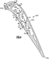
- Figure 4 illustrates a further example airfoil 260 that is the same as the airfoil 60 except that the orientation of the ribs 64 is flipped such that the triangular passages 74 border the first side wall 62c and the passages 66b/66c/66d border the second side wall 62d.
- the passages 66b/66c/66d may be part of a serpentine circuit as discussed above.
- the passages 66c/66d may exclude any film cooling apertures and the passage 66b may have film cooling apertures such that the cooling air is discharged forward of the gauge point of the airfoil 260.
- the gauge point is the axial location on the suction side of an airfoil where the gaspath Mach number is maximum and gaspath flow changes from accelerating to decelerating. Injecting the cooling air into the accelerating flow forward of the gauge point facilitates less loss than injecting into the decelerating flow.
- the airfoils 60/160/260 include cooling apertures 78. Flow arrows of the cooling air are shown and a depiction of a flow arrow that extends through a wall indicates that there is a cooling hole or aperture 78 at that location (not all of which are numbered).
- the cooling apertures 78 provide additional cooling schemes to further enhance cooling. For instance, some of the cooling apertures 78 may serve as impingement holes to concentrate flow onto the inside surface of the adjacent portion of the wall 62. Other of the cooling apertures that are on the wall 62 serve as film cooling holes for the exterior surfaces of the airfoil wall 62. Other of the cooling apertures 78 that are on the long portions of the second and third arms 68/70 serve as feed holes to feed cooling air from the serpentine cooling air circuit 76 into the passage 74. Therefore, various configurations of the cooling apertures 78 can be used to control cooling air flow in the respective airfoils. In these examples, although cooling air may flow radially, the cooling apertures 78 provide for impingement cooling and axial flow of the cooling air.
Landscapes
- Engineering & Computer Science (AREA)
- Mechanical Engineering (AREA)
- General Engineering & Computer Science (AREA)
- Architecture (AREA)
- Structures Of Non-Positive Displacement Pumps (AREA)
- Turbine Rotor Nozzle Sealing (AREA)
Abstract
Description
- A gas turbine engine typically includes a fan section, a compressor section, a combustor section and a turbine section. Air entering the compressor section is compressed and delivered into the combustion section where it is mixed with fuel and ignited to generate a high-speed exhaust gas flow. The high-speed exhaust gas flow expands through the turbine section to drive the compressor and the fan section. The compressor section typically includes low and high pressure compressors, and the turbine section includes low and high pressure turbines.
- The high pressure turbine drives the high pressure compressor through an outer shaft to form a high spool, and the low pressure turbine drives the low pressure compressor through an inner shaft to form a low spool. The fan section may also be driven by the low inner shaft. A direct drive gas turbine engine includes a fan section driven by the low spool such that the low pressure compressor, low pressure turbine and fan section rotate at a common speed in a common direction.
- According to an aspect of the present disclosure, there is provided an airfoil including an airfoil wall that defines a leading end, a trailing end, a first side wall, and a second side wall. A rib connects the first and second side walls of the airfoil wall. The rib includes first and second unbranched arms initiating at the second side wall and extending there from to meet at a node, and a third unbranched arm initiating at the first side wall. The third unbranched arm extends perpendicularly there from and connects at either the node, the first unbranched arm, or the unbranched second arm.
- In a further embodiment of any of the foregoing embodiments, the third unbranched arm connects at the node.
- In a further embodiment of any of the foregoing embodiments, the third unbranched arm connects at one of the first or second unbranched arms.
- In a further embodiment of any of the foregoing embodiments, the first and second unbranched arms together with the second side define a triangular passage.
- In a further embodiment of any of the foregoing embodiments, with the second side wall as a base, the triangular passage defines a height (h) and a width (w) that have a ratio of h/w of less than 0.75.
- In a further embodiment of any of the foregoing embodiments, the ratio is less than 0.5.
- In a further embodiment of any of the foregoing embodiments, the third arm and the first side wall border a passage that is flow isolated from the triangular passage.
- In a further embodiment of any of the foregoing embodiments, the first and second arms are of substantially equal length.
- According to an aspect of the present disclosure, there is provided an airfoil including an airfoil wall that defines a leading end, a trailing end, a first side wall, and a second side wall. A pair of ribs define there between a pentagonal passage. Each said rib connects the first and second side walls of the airfoil wall and including first and second unbranched arms initiating at one of the first side wall or the second side wall and extending there from to meet at a node, the first and second unbranched arms together with the one of the first side wall or the second side wall defining a triangular passage there between. A third unbranched arm initiates at the other of the first side wall or the second side wall, the third unbranched arm extends perpendicularly there from and connecting at the node.
- In a further embodiment of any of the foregoing embodiments, the pentagonal passage has a longest side defined by the first side wall.
- In a further embodiment of any of the foregoing embodiments, the second side wall is a suction side.
- In a further embodiment of any of the foregoing embodiments, the pentagonal passage is part of a serpentine cooling air circuit.
- In a further embodiment of any of the foregoing embodiments, the pentagonal passage excludes any cooling apertures through the first and second side walls.
- According to an aspect of the present disclosure, there is provided a gas turbine engine including a compressor section, a combustor in fluid communication with the compressor section, and a turbine section in fluid communication with the combustor. The turbine section has an airfoil that includes an airfoil wall that defines a leading end, a trailing end, a first side wall, and a second side wall. A rib connects the first and second side walls of the airfoil wall. The rib has first and second unbranched arms initiating at the second side and extending there from to meet at a node, and a third unbranched arm initiating at the first side wall. The third unbranched arm extends perpendicularly there from and connects at either the node, the first unbranched arm, or the unbranched second arm.
- In a further embodiment of any of the foregoing embodiments, the first and second unbranched arms together with the second side define a triangular passage.
- In a further embodiment of any of the foregoing embodiments, with the second side wall as a base, the triangular passage defines a height (h) and a width (w) that have a ratio of h/w of less than 0.5.
- In a further embodiment of any of the foregoing embodiments, the third arm and the first side wall border a passage that is flow isolated from the triangular passage.
- In a further embodiment of any of the foregoing embodiments, the first and second arms are of substantially equal length.
- In a further embodiment of any of the foregoing embodiments, the third unbranched arm connects at the node.
- The various features and advantages of the present disclosure will become apparent to those skilled in the art from the following detailed description. The drawings that accompany the detailed description can be briefly described as follows.
-
Figure 1 illustrates a gas turbine engine. -
Figure 2A illustrates a sectioned view of an airfoil from the gas turbine engine. -
Figure 2B illustrates a view of a portion of the airfoil ofFigure 2A . -
Figure 3 illustrates another example airfoil for the gas turbine engine. -
Figure 4 illustrates another example airfoil for the gas turbine engine. -
Figure 1 schematically illustrates agas turbine engine 20. Thegas turbine engine 20 is disclosed herein as a two-spool turbofan that generally incorporates afan section 22, acompressor section 24, acombustor section 26 and aturbine section 28. Thefan section 22 drives air along a bypass flow path B in a bypass duct defined within ahousing 15 such as a fan case or nacelle, and also drives air along a core flow path C for compression and communication into thecombustor section 26 then expansion through theturbine section 28. Although depicted as a two-spool turbofan gas turbine engine in the disclosed non-limiting embodiment, it should be understood that the concepts described herein are not limited to use with two-spool turbofans as the teachings may be applied to other types of turbine engines including three-spool architectures. - The
exemplary engine 20 generally includes alow speed spool 30 and ahigh speed spool 32 mounted for rotation about an engine central longitudinal axis A relative to an enginestatic structure 36 viaseveral bearing systems 38. It should be understood thatvarious bearing systems 38 at various locations may alternatively or additionally be provided, and the location ofbearing systems 38 may be varied as appropriate to the application. - The
low speed spool 30 generally includes aninner shaft 40 that interconnects, a first (or low)pressure compressor 44 and a first (or low)pressure turbine 46. Theinner shaft 40 is connected to thefan 42 through a speed change mechanism, which in exemplarygas turbine engine 20 is illustrated as a gearedarchitecture 48 to drive afan 42 at a lower speed than thelow speed spool 30. Thehigh speed spool 32 includes anouter shaft 50 that interconnects a second (or high)pressure compressor 52 and a second (or high)pressure turbine 54. Acombustor 56 is arranged inexemplary gas turbine 20 between thehigh pressure compressor 52 and thehigh pressure turbine 54. Amid-turbine frame 57 of the enginestatic structure 36 may be arranged generally between thehigh pressure turbine 54 and thelow pressure turbine 46. Themid-turbine frame 57 further supports bearingsystems 38 in theturbine section 28. Theinner shaft 40 and theouter shaft 50 are concentric and rotate viabearing systems 38 about the engine central longitudinal axis A which is collinear with their longitudinal axes. - The core airflow is compressed by the
low pressure compressor 44 then thehigh pressure compressor 52, mixed and burned with fuel in thecombustor 56, then expanded through thehigh pressure turbine 54 andlow pressure turbine 46. Themid-turbine frame 57 includesairfoils 59 which are in the core airflow path C. Theturbines low speed spool 30 andhigh speed spool 32 in response to the expansion. It will be appreciated that each of the positions of thefan section 22,compressor section 24,combustor section 26,turbine section 28, and fandrive gear system 48 may be varied. For example,gear system 48 may be located aft of the low pressure compressor, or aft of thecombustor section 26 or even aft ofturbine section 28, andfan 42 may be positioned forward or aft of the location ofgear system 48. - The
engine 20 in one example is a high-bypass geared aircraft engine. In a further example, theengine 20 bypass ratio is greater than about six (6), with an example embodiment being greater than about ten (10), the gearedarchitecture 48 is an epicyclic gear train, such as a planetary gear system or other gear system, with a gear reduction ratio of greater than about 2.3 and thelow pressure turbine 46 has a pressure ratio that is greater than about five. In one disclosed embodiment, theengine 20 bypass ratio is greater than about ten (10:1), the fan diameter is significantly larger than that of thelow pressure compressor 44, and thelow pressure turbine 46 has a pressure ratio that is greater than about five 5:1.Low pressure turbine 46 pressure ratio is pressure measured prior to inlet oflow pressure turbine 46 as related to the pressure at the outlet of thelow pressure turbine 46 prior to an exhaust nozzle. The gearedarchitecture 48 may be an epicycle gear train, such as a planetary gear system or other gear system, with a gear reduction ratio of greater than about 2.3:1 and less than about 5:1. It should be understood, however, that the above parameters are only exemplary of one embodiment of a geared architecture engine and that the present invention is applicable to other gas turbine engines including direct drive turbofans. - A significant amount of thrust is provided by the bypass flow B due to the high bypass ratio. The
fan section 22 of theengine 20 is designed for a particular flight condition -- typically cruise at about 0.8 Mach and about 35,000 feet (10,668 meters). The flight condition of 0.8 Mach and 35,000 ft (10,668 meters), with the engine at its best fuel consumption - also known as "bucket cruise Thrust Specific Fuel Consumption ('TSFC')" - is the industry standard parameter of lbm of fuel being burned divided by lbf of thrust the engine produces at that minimum point. "Low fan pressure ratio" is the pressure ratio across the fan blade alone, without a Fan Exit Guide Vane ("FEGV") system. The low fan pressure ratio as disclosed herein according to one non-limiting embodiment is less than about 1.45. "Low corrected fan tip speed" is the actual fan tip speed in ft/sec divided by an industry standard temperature correction of [(Tram °R) / (518.7 °R)]0.5. The "Low corrected fan tip speed" as disclosed herein according to one non-limiting embodiment is less than about 1150 ft / second (350.5 meters/second). -
Figure 2A shows a representation of a sectionedairfoil 60 used in the turbine engine 20 (see alsoFigure 1 ), andFigure 2B illustrates a view of the region identified inFigure 1 . Theairfoil 60 is a turbine blade; however, it is to be understood that this disclosure is also applicable to cooled blades or vanes. - The
airfoil 60 includes an (outer)airfoil wall 62 that spans in a radial direction and delimits the aerodynamic profile of theairfoil 60. In this regard, thewall 62 defines aleading end 62a, a trailingend 62b, and first andsecond side walls 62c/62d that join theleading end 62a and the trailingend 62b. In this example, thefirst side wall 62c is a pressure side and thesecond side wall 62d is a suction side. The terminology "first" and "second" as used herein is to differentiate that there are two architecturally distinct components or features. It is to be understood that the terms "first" and "second" are interchangeable in the embodiments herein such that a first component or feature could alternatively be termed as a second component or feature, and vice versa. - The
airfoil 60 further includes one ormore ribs 64. In the illustrated example, the airfoil has twosuch ribs 64, although in modified examples theairfoil 60 can include asingle rib 64 or more than tworibs 64. And although asingle rib 64 is described in some instances herein, it is to be understood that eachsuch rib 64 has the described attributes of thesingle rib 64. Theribs 64 and arib 65 partition the interior cavity of theairfoil 60 into several passages, which in this example include aforward-most passage 66a, anaft-most passage 66d, a forwardintermediate passage 66b, and an aftintermediate passage 66c. - Each
rib 64 connects the first andsecond side walls 62c/62d and is generally longitudinally elongated between an inner diameter and outer diameter of theairfoil 60. Except for connection through theairfoil wall 62, theribs 64 are disjoined from each other. As used herein, the term "disjoined" refers to theribs 64 excluding any structural attachments to each other. Such an attachment configuration permits eachrib 64 to reinforce theside walls 62c/62d and facilitate reduction in bulging from internal pressure, while still permitting theribs 64 to move and thermally expand and contract at a different rate than theside walls 62c/62d during thermal cycling and without interference fromadjacent ribs 64. - Each
rib 64 includes first and secondunbranched arms 68/70 that initiate at thesecond side wall 62d and extend there from to meet at a node, identified at N. A thirdunbranched arm 72 initiates at thefirst side wall 62c and extends perpendicularly (locally) there from. The thirdunbranched side arm 72 connects to the first and secondunbranched arms 68/70 at the node (N) in this example. The perpendicular orientation provides the shortest distance to the node (N), thereby facilitating reductions in airfoil mass. The term "unbranched" refers to an arm that has no other arms extending off of it between its initiation point and the node to which it connects. It is to be further understood that the term "perpendicular" or variations thereof encompass deviations from 90° due to manufacturing tolerances or other variances, such as deviations of 90° +/- 10%. - The first and second
unbranched arms 68/70 together with thesecond side wall 62d define a triangular passage 74 (triangular in cross-sectional shape, taken in a plane perpendicular to the radial direction). The tworibs 64 in theairfoil 60 in this example also define the aft-intermediate passage 66c there between. In the illustrated example, the aft-intermediate passage 66c is a pentagonal passage (pentagonal in cross-sectional shape) that is bound by the thirdunbranched arms 72, the firstunbranched arm 68 of one of the aft one of theribs 64, the secondunbranched arm 70 of the forward one of theribs 64, and thefirst side wall 62c. - Cooling air, such as bleed air from the
compressor section 24, is fed into and through thepassages 66a/66b/66c/66d/74. For example, thetriangular passages 74 are radial flow passages and thepassages 66a/66b/66c/66d are a part of a serpentine cooling air circuit, generally denoted at 76. In this regard, thetriangular passages 74 are fed from a radially inner location of the airfoil 60 (and/or radially outer location if theairfoil 60 is a vane) and the cooling air flows radially outwards. The cooling air is then discharged through the tip of the airfoil and/or through one ormore cooling apertures 78. Thetriangular passages 74 serve to cool thesecond side wall 62d. - Cooling air for the
passages 66a/66b/66c/66d is also fed from a radially inner location to either thepassage 66a (for a forward-to-aft flow strategy) orpassage 66d (for an aft-to-forward flow strategy). The cooling air then flow sequentially through thepassages 66a/66b/66c/66d, turning in a platform or tip to flow from one passage to the next. Thepassages 66a/66b/66c/66d serve to cool thefirst side wall 62c. As will be appreciated, alternate cooling air feed schemes may alternatively be used, such as but not limited to, separately fed serpentine passage groups. - In the illustrated example, the
passages 74 are flow isolated from thepassages 66a/66b/66c/66d. As used herein, the phrase "flow isolated" or variations thereof refers to passages, channels, or both that are not fluidly connected to each other within theairfoil 60 such that air cannot flow within theairfoil 60 from one passage or channel to the other passage or channel. For instance, the cooling of thefirst side wall 62c is in essence segregated from the cooling of thesecond side wall 62d. This enables the cooling to be controlled and optimized for eachside wall 62c/62d. As an example, different cooling air pressures are utilized in thetriangular passages 74 versus thepassages 66a/66b/66c/66d. Such pressures can be controlled, for example, by metering orifices or the like at or near the inlets of the cooling air into thepassages 66a/66b/66c/66d/74. - Additionally, Coriolis effects cause relatively high heat transfer on the
first side wall 62c and relatively low heat transfer on thesecond side wall 62d in radially outward cooling air flow schemes, facilitating reduction in thermal stresses between the relativelyhot side walls 62c/62d and the relativelycool ribs 64. This is further facilitated by the geometry of thepentagonal passage 66c. For example, thepassage 66c has a longest side defined by thefirst side wall 62c and a shortest side defined by one or both of theunbranched arms 68/70. - In additional examples, to facilitate additional cooling and performance enhancement, the
triangular passages 74 have low aspect ratio geometries. For instance, referring to thetriangular passage 74 inFigure 2B , thesecond side wall 62d serves as the base of the triangle and defines a width (w). Thearms 68/70 serve as the sides of the triangle and define a height (h). Such a width and height are defined by straight-line distances with respect to mid-line axes of the walls and intersections of such axes. In one example, thetriangular passage 74 has an aspect ratio h/w of less than 0.75. A low aspect ratio enables fewer of thetriangular passages 74 to cool thesecond side wall 62d, thereby reducing the number of ribs and in turn reducing airfoil mass. In a further example, thetriangular passage 74 has an aspect ratio h/w of less than 0.5, which may facilitate further weight reduction as well as minimize reduction in heat transfer due to Coriolis effects. - In an additional example, the
unbranched arms 68/70 are of substantially equal length. For example, the lengths are taken as straight line distances with respect to mid-line axes of the walls and intersections of such axes. The term "substantially equal" or variations thereof encompass deviations due to manufacturing tolerances or other variances, such as deviations of 10% between the lengths of theunbranched arms 68/70. The configuration in which theunbranched arms 68/70 are of substantially equal length facilitates balancing heat transfer and thermal stresses. Additionally, as theunbranched arms 68/70 are non-parallel with thesecond side wall 62d, thetriangular passage 74 permits flexibility for thesecond side wall 62d to thermally expand/contract. For example, differences in thermal growth between thesecond side wall 62d and therib 64 are taken up by the height of the triangle such that in a relatively cold state the triangle elongates in height and in a relatively hot state the triangle compresses in height. - The configuration of the rib or
ribs 64 provides additional cooling configurations. For instance, as shown in theairfoil 160 inFigure 3 , the thirdunbranched arm 72 connects to the secondunbranched arm 70 at the node (N1) in this example rather than a node that is at the apex of the triangle as in the example inFigure 2A . As will be appreciated, the thirdunbranched arm 72 may alternatively connect to the firstunbranched arm 68. In either case, theunbranched arm 72 is longer than in the example inFigure 2A and thus adds mass in comparison. However, changing the location of the node facilitates changing the size of thepassages 66b/66c/66d/74 to further tailor cooling effects. -
Figure 4 illustrates afurther example airfoil 260 that is the same as theairfoil 60 except that the orientation of theribs 64 is flipped such that thetriangular passages 74 border thefirst side wall 62c and thepassages 66b/66c/66d border thesecond side wall 62d. For example, such a configuration facilitates reducing the amount of cooling air flow for high heat transfer on the pressure side. Additionally, thepassages 66b/66c/66d may be part of a serpentine circuit as discussed above. Thepassages 66c/66d may exclude any film cooling apertures and thepassage 66b may have film cooling apertures such that the cooling air is discharged forward of the gauge point of theairfoil 260. The gauge point is the axial location on the suction side of an airfoil where the gaspath Mach number is maximum and gaspath flow changes from accelerating to decelerating. Injecting the cooling air into the accelerating flow forward of the gauge point facilitates less loss than injecting into the decelerating flow. - In additional examples, the
airfoils 60/160/260 include coolingapertures 78. Flow arrows of the cooling air are shown and a depiction of a flow arrow that extends through a wall indicates that there is a cooling hole oraperture 78 at that location (not all of which are numbered). - The cooling
apertures 78 provide additional cooling schemes to further enhance cooling. For instance, some of thecooling apertures 78 may serve as impingement holes to concentrate flow onto the inside surface of the adjacent portion of thewall 62. Other of the cooling apertures that are on thewall 62 serve as film cooling holes for the exterior surfaces of theairfoil wall 62. Other of thecooling apertures 78 that are on the long portions of the second andthird arms 68/70 serve as feed holes to feed cooling air from the serpentinecooling air circuit 76 into thepassage 74. Therefore, various configurations of thecooling apertures 78 can be used to control cooling air flow in the respective airfoils. In these examples, although cooling air may flow radially, the coolingapertures 78 provide for impingement cooling and axial flow of the cooling air. - Although a combination of features is shown in the illustrated examples, not all of them need to be combined to realize the benefits of various embodiments of this disclosure. In other words, a system designed according to an embodiment of this disclosure will not necessarily include all of the features shown in any one of the Figures or all of the portions schematically shown in the Figures. Moreover, selected features of one example embodiment may be combined with selected features of other example embodiments.
- The preceding description is exemplary rather than limiting in nature. Variations and modifications to the disclosed examples may become apparent to those skilled in the art that do not necessarily depart from this disclosure. The scope of legal protection given to this disclosure can only be determined by studying the following claims.
Claims (14)
- An airfoil comprising:an airfoil wall defining a leading end, a trailing end, a first side wall, and a second side wall; anda rib connecting the first and second side walls of the airfoil wall, the rib includingfirst and second unbranched arms initiating at the second side wall and extending there from to meet at a node, anda third unbranched arm initiating at the first side wall, the third unbranched arm extending perpendicularly there from and connecting at either the node, the first unbranched arm, or the unbranched second arm.
- The airfoil as recited in claim 1, wherein the third unbranched arm connects at the node.
- The airfoil as recited in claim 1, wherein the third unbranched arm connects at one of the first or second unbranched arms.
- The airfoil as recited in claim 1, 2 or 3, wherein the first and second unbranched arms together with the second side define a triangular passage.
- The airfoil as recited in claim 4, wherein, with the second side wall as a base, the triangular passage defines a height (h) and a width (w) that have a ratio of h/w of less than 0.75.
- The airfoil as recited in claim 5, wherein the ratio is less than 0.5.
- The airfoil as recited in any of claims 4 to 6, wherein the third arm and the first side wall border a passage that is flow isolated from the triangular passage.
- The airfoil as recited in any preceding claim, wherein the first and second arms are of substantially equal length.
- An airfoil comprising:an airfoil wall defining a leading end, a trailing end, a first side wall, and a second side wall; anda pair of ribs defining there between a pentagonal passage, each said rib connecting the first and second side walls of the airfoil wall and includingfirst and second unbranched arms initiating at one of the first side wall or the second side wall and extending there from to meet at a node, the first and second unbranched arms together with the one of the first side wall or the second side wall defining a triangular passage there between, anda third unbranched arm initiating at the other of the first side wall or the second side wall, the third unbranched arm extending perpendicularly there from and connecting at the node.
- The airfoil as recited in claim 9, wherein the pentagonal passage has a longest side defined by the first side wall.
- The airfoil as recited in claim 10, wherein the second side wall is a suction side.
- The airfoil as recited in claim 9, 10 or 11, wherein the pentagonal passage is part of a serpentine cooling air circuit.
- The airfoil as recited in claim 12, wherein the pentagonal passage excludes any cooling apertures through the first and second side walls.
- A gas turbine engine comprising:a compressor section;a combustor in fluid communication with the compressor section; anda turbine section in fluid communication with the combustor,the turbine section having an airfoil as recited in any preceding claim.
Applications Claiming Priority (1)
| Application Number | Priority Date | Filing Date | Title |
|---|---|---|---|
| US16/850,593 US11220912B2 (en) | 2020-04-16 | 2020-04-16 | Airfoil with y-shaped rib |
Publications (2)
| Publication Number | Publication Date |
|---|---|
| EP3896257A1 true EP3896257A1 (en) | 2021-10-20 |
| EP3896257B1 EP3896257B1 (en) | 2024-09-25 |
Family
ID=75529885
Family Applications (1)
| Application Number | Title | Priority Date | Filing Date |
|---|---|---|---|
| EP21168388.3A Active EP3896257B1 (en) | 2020-04-16 | 2021-04-14 | Airfoil with y-shaped rib |
Country Status (2)
| Country | Link |
|---|---|
| US (1) | US11220912B2 (en) |
| EP (1) | EP3896257B1 (en) |
Families Citing this family (6)
| Publication number | Priority date | Publication date | Assignee | Title |
|---|---|---|---|---|
| US11629602B2 (en) * | 2021-06-17 | 2023-04-18 | Raytheon Technologies Corporation | Cooling schemes for airfoils for gas turbine engines |
| EP4343116A3 (en) * | 2022-09-26 | 2024-04-17 | RTX Corporation | Airfoils with lobed cooling cavities |
| US12215601B2 (en) | 2023-02-17 | 2025-02-04 | Rtx Corporation | Air foil with staggered cooling hole configuration |
| US12065944B1 (en) | 2023-03-07 | 2024-08-20 | Rtx Corporation | Airfoils with mixed skin passageway cooling |
| US12540552B2 (en) | 2023-03-07 | 2026-02-03 | Rtx Corporation | Airfoils with axial leading edge impingement slots |
| US12404775B1 (en) * | 2024-09-16 | 2025-09-02 | Rtx Corporation | Turbine blade with cooling channels |
Citations (3)
| Publication number | Priority date | Publication date | Assignee | Title |
|---|---|---|---|---|
| US6126396A (en) * | 1998-12-09 | 2000-10-03 | General Electric Company | AFT flowing serpentine airfoil cooling circuit with side wall impingement cooling chambers |
| US20100254824A1 (en) * | 2008-03-31 | 2010-10-07 | Shailendra Naik | Gas turbine airfoil |
| US20190136699A1 (en) * | 2017-11-07 | 2019-05-09 | United Technologies Corporation | Modified structural truss for airfoils |
Family Cites Families (16)
| Publication number | Priority date | Publication date | Assignee | Title |
|---|---|---|---|---|
| US5156526A (en) * | 1990-12-18 | 1992-10-20 | General Electric Company | Rotation enhanced rotor blade cooling using a single row of coolant passageways |
| US5246340A (en) * | 1991-11-19 | 1993-09-21 | Allied-Signal Inc. | Internally cooled airfoil |
| US6183198B1 (en) * | 1998-11-16 | 2001-02-06 | General Electric Company | Airfoil isolated leading edge cooling |
| US6206638B1 (en) | 1999-02-12 | 2001-03-27 | General Electric Company | Low cost airfoil cooling circuit with sidewall impingement cooling chambers |
| US6832889B1 (en) * | 2003-07-09 | 2004-12-21 | General Electric Company | Integrated bridge turbine blade |
| US6984103B2 (en) * | 2003-11-20 | 2006-01-10 | General Electric Company | Triple circuit turbine blade |
| US7097426B2 (en) * | 2004-04-08 | 2006-08-29 | General Electric Company | Cascade impingement cooled airfoil |
| US7217092B2 (en) | 2004-04-14 | 2007-05-15 | General Electric Company | Method and apparatus for reducing turbine blade temperatures |
| US7131818B2 (en) | 2004-11-02 | 2006-11-07 | United Technologies Corporation | Airfoil with three-pass serpentine cooling channel and microcircuit |
| US7569172B2 (en) * | 2005-06-23 | 2009-08-04 | United Technologies Corporation | Method for forming turbine blade with angled internal ribs |
| US7293961B2 (en) * | 2005-12-05 | 2007-11-13 | General Electric Company | Zigzag cooled turbine airfoil |
| US7296973B2 (en) * | 2005-12-05 | 2007-11-20 | General Electric Company | Parallel serpentine cooled blade |
| US10053990B2 (en) * | 2016-05-12 | 2018-08-21 | General Electric Company | Internal rib with defined concave surface curvature for airfoil |
| US10465525B2 (en) | 2016-07-22 | 2019-11-05 | General Electric Company | Blade with internal rib having corrugated surface(s) |
| US10626734B2 (en) * | 2017-10-03 | 2020-04-21 | United Technologies Corporation | Airfoil having internal hybrid cooling cavities |
| US10871074B2 (en) * | 2019-02-28 | 2020-12-22 | Raytheon Technologies Corporation | Blade/vane cooling passages |
-
2020
- 2020-04-16 US US16/850,593 patent/US11220912B2/en active Active
-
2021
- 2021-04-14 EP EP21168388.3A patent/EP3896257B1/en active Active
Patent Citations (3)
| Publication number | Priority date | Publication date | Assignee | Title |
|---|---|---|---|---|
| US6126396A (en) * | 1998-12-09 | 2000-10-03 | General Electric Company | AFT flowing serpentine airfoil cooling circuit with side wall impingement cooling chambers |
| US20100254824A1 (en) * | 2008-03-31 | 2010-10-07 | Shailendra Naik | Gas turbine airfoil |
| US20190136699A1 (en) * | 2017-11-07 | 2019-05-09 | United Technologies Corporation | Modified structural truss for airfoils |
Also Published As
| Publication number | Publication date |
|---|---|
| US11220912B2 (en) | 2022-01-11 |
| US20210324741A1 (en) | 2021-10-21 |
| EP3896257B1 (en) | 2024-09-25 |
Similar Documents
| Publication | Publication Date | Title |
|---|---|---|
| EP3896257B1 (en) | Airfoil with y-shaped rib | |
| EP3543464B1 (en) | Dual cavity baffle | |
| EP3783197B1 (en) | Airfoil with rib having connector arms | |
| EP3060760B1 (en) | Airfoil with skin core cooling | |
| EP3056672B1 (en) | Inclined crossover passages for airfoils | |
| EP3034793B1 (en) | Gas turbine engine component with increased cooling capacity | |
| EP3783198B1 (en) | Airfoil with ribs having connector arms and apertures defining a cooling circuit | |
| US20240271536A1 (en) | Airfoil with ribs defining shaped cooling channel | |
| EP3150800B1 (en) | Airfoil baffle with wedge region | |
| EP3112596A1 (en) | Gas turbine engine airfoil with bi-axial skin cooling passage and corresponding gas turbine engine | |
| US11959397B2 (en) | Airfoil with cooling passage network having arced leading edge | |
| EP3533971B1 (en) | Airfoil with varying wall thickness | |
| EP4538503A1 (en) | Turbine component and gas turbine engine | |
| US20200332663A1 (en) | Airfoil with cavity lobe adjacent cooling passage network | |
| EP3670841B1 (en) | Airfoil with hybrid skincore passage resupply | |
| US11952911B2 (en) | Airfoil with connecting rib | |
| EP3650641A1 (en) | Airfoil with cooling passage circuit through platforms and airfoil section | |
| EP3819473B1 (en) | Trailing edge insert for airfoil vane | |
| EP3822456A1 (en) | Airfoil having a turn channel with split and flow-through | |
| EP3650651A1 (en) | Airfoil with wall that tapers in thickness |
Legal Events
| Date | Code | Title | Description |
|---|---|---|---|
| PUAI | Public reference made under article 153(3) epc to a published international application that has entered the european phase |
Free format text: ORIGINAL CODE: 0009012 |
|
| STAA | Information on the status of an ep patent application or granted ep patent |
Free format text: STATUS: THE APPLICATION HAS BEEN PUBLISHED |
|
| AK | Designated contracting states |
Kind code of ref document: A1 Designated state(s): AL AT BE BG CH CY CZ DE DK EE ES FI FR GB GR HR HU IE IS IT LI LT LU LV MC MK MT NL NO PL PT RO RS SE SI SK SM TR |
|
| B565 | Issuance of search results under rule 164(2) epc |
Effective date: 20210825 |
|
| STAA | Information on the status of an ep patent application or granted ep patent |
Free format text: STATUS: REQUEST FOR EXAMINATION WAS MADE |
|
| 17P | Request for examination filed |
Effective date: 20220407 |
|
| RBV | Designated contracting states (corrected) |
Designated state(s): AL AT BE BG CH CY CZ DE DK EE ES FI FR GB GR HR HU IE IS IT LI LT LU LV MC MK MT NL NO PL PT RO RS SE SI SK SM TR |
|
| STAA | Information on the status of an ep patent application or granted ep patent |
Free format text: STATUS: EXAMINATION IS IN PROGRESS |
|
| 17Q | First examination report despatched |
Effective date: 20230519 |
|
| RAP3 | Party data changed (applicant data changed or rights of an application transferred) |
Owner name: RTX CORPORATION |
|
| GRAP | Despatch of communication of intention to grant a patent |
Free format text: ORIGINAL CODE: EPIDOSNIGR1 |
|
| STAA | Information on the status of an ep patent application or granted ep patent |
Free format text: STATUS: GRANT OF PATENT IS INTENDED |
|
| INTG | Intention to grant announced |
Effective date: 20240515 |
|
| GRAS | Grant fee paid |
Free format text: ORIGINAL CODE: EPIDOSNIGR3 |
|
| GRAA | (expected) grant |
Free format text: ORIGINAL CODE: 0009210 |
|
| STAA | Information on the status of an ep patent application or granted ep patent |
Free format text: STATUS: THE PATENT HAS BEEN GRANTED |
|
| AK | Designated contracting states |
Kind code of ref document: B1 Designated state(s): AL AT BE BG CH CY CZ DE DK EE ES FI FR GB GR HR HU IE IS IT LI LT LU LV MC MK MT NL NO PL PT RO RS SE SI SK SM TR |
|
| REG | Reference to a national code |
Ref country code: GB Ref legal event code: FG4D |
|
| REG | Reference to a national code |
Ref country code: CH Ref legal event code: EP |
|
| REG | Reference to a national code |
Ref country code: DE Ref legal event code: R096 Ref document number: 602021019163 Country of ref document: DE |
|
| REG | Reference to a national code |
Ref country code: IE Ref legal event code: FG4D |
|
| REG | Reference to a national code |
Ref country code: LT Ref legal event code: MG9D |
|
| PG25 | Lapsed in a contracting state [announced via postgrant information from national office to epo] |
Ref country code: NO Free format text: LAPSE BECAUSE OF FAILURE TO SUBMIT A TRANSLATION OF THE DESCRIPTION OR TO PAY THE FEE WITHIN THE PRESCRIBED TIME-LIMIT Effective date: 20241225 |
|
| PG25 | Lapsed in a contracting state [announced via postgrant information from national office to epo] |
Ref country code: GR Free format text: LAPSE BECAUSE OF FAILURE TO SUBMIT A TRANSLATION OF THE DESCRIPTION OR TO PAY THE FEE WITHIN THE PRESCRIBED TIME-LIMIT Effective date: 20241226 Ref country code: FI Free format text: LAPSE BECAUSE OF FAILURE TO SUBMIT A TRANSLATION OF THE DESCRIPTION OR TO PAY THE FEE WITHIN THE PRESCRIBED TIME-LIMIT Effective date: 20240925 |
|
| PG25 | Lapsed in a contracting state [announced via postgrant information from national office to epo] |
Ref country code: BG Free format text: LAPSE BECAUSE OF FAILURE TO SUBMIT A TRANSLATION OF THE DESCRIPTION OR TO PAY THE FEE WITHIN THE PRESCRIBED TIME-LIMIT Effective date: 20240925 |
|
| PG25 | Lapsed in a contracting state [announced via postgrant information from national office to epo] |
Ref country code: LV Free format text: LAPSE BECAUSE OF FAILURE TO SUBMIT A TRANSLATION OF THE DESCRIPTION OR TO PAY THE FEE WITHIN THE PRESCRIBED TIME-LIMIT Effective date: 20240925 |
|
| PG25 | Lapsed in a contracting state [announced via postgrant information from national office to epo] |
Ref country code: RS Free format text: LAPSE BECAUSE OF FAILURE TO SUBMIT A TRANSLATION OF THE DESCRIPTION OR TO PAY THE FEE WITHIN THE PRESCRIBED TIME-LIMIT Effective date: 20241225 |
|
| REG | Reference to a national code |
Ref country code: NL Ref legal event code: MP Effective date: 20240925 |
|
| PG25 | Lapsed in a contracting state [announced via postgrant information from national office to epo] |
Ref country code: RS Free format text: LAPSE BECAUSE OF FAILURE TO SUBMIT A TRANSLATION OF THE DESCRIPTION OR TO PAY THE FEE WITHIN THE PRESCRIBED TIME-LIMIT Effective date: 20241225 Ref country code: NO Free format text: LAPSE BECAUSE OF FAILURE TO SUBMIT A TRANSLATION OF THE DESCRIPTION OR TO PAY THE FEE WITHIN THE PRESCRIBED TIME-LIMIT Effective date: 20241225 Ref country code: LV Free format text: LAPSE BECAUSE OF FAILURE TO SUBMIT A TRANSLATION OF THE DESCRIPTION OR TO PAY THE FEE WITHIN THE PRESCRIBED TIME-LIMIT Effective date: 20240925 Ref country code: GR Free format text: LAPSE BECAUSE OF FAILURE TO SUBMIT A TRANSLATION OF THE DESCRIPTION OR TO PAY THE FEE WITHIN THE PRESCRIBED TIME-LIMIT Effective date: 20241226 Ref country code: FI Free format text: LAPSE BECAUSE OF FAILURE TO SUBMIT A TRANSLATION OF THE DESCRIPTION OR TO PAY THE FEE WITHIN THE PRESCRIBED TIME-LIMIT Effective date: 20240925 Ref country code: BG Free format text: LAPSE BECAUSE OF FAILURE TO SUBMIT A TRANSLATION OF THE DESCRIPTION OR TO PAY THE FEE WITHIN THE PRESCRIBED TIME-LIMIT Effective date: 20240925 |
|
| REG | Reference to a national code |
Ref country code: AT Ref legal event code: MK05 Ref document number: 1726780 Country of ref document: AT Kind code of ref document: T Effective date: 20240925 |
|
| PG25 | Lapsed in a contracting state [announced via postgrant information from national office to epo] |
Ref country code: NL Free format text: LAPSE BECAUSE OF FAILURE TO SUBMIT A TRANSLATION OF THE DESCRIPTION OR TO PAY THE FEE WITHIN THE PRESCRIBED TIME-LIMIT Effective date: 20240925 |
|
| PG25 | Lapsed in a contracting state [announced via postgrant information from national office to epo] |
Ref country code: IS Free format text: LAPSE BECAUSE OF FAILURE TO SUBMIT A TRANSLATION OF THE DESCRIPTION OR TO PAY THE FEE WITHIN THE PRESCRIBED TIME-LIMIT Effective date: 20250125 Ref country code: PT Free format text: LAPSE BECAUSE OF FAILURE TO SUBMIT A TRANSLATION OF THE DESCRIPTION OR TO PAY THE FEE WITHIN THE PRESCRIBED TIME-LIMIT Effective date: 20250127 |
|
| PG25 | Lapsed in a contracting state [announced via postgrant information from national office to epo] |
Ref country code: RO Free format text: LAPSE BECAUSE OF FAILURE TO SUBMIT A TRANSLATION OF THE DESCRIPTION OR TO PAY THE FEE WITHIN THE PRESCRIBED TIME-LIMIT Effective date: 20240925 Ref country code: SM Free format text: LAPSE BECAUSE OF FAILURE TO SUBMIT A TRANSLATION OF THE DESCRIPTION OR TO PAY THE FEE WITHIN THE PRESCRIBED TIME-LIMIT Effective date: 20240925 |
|
| PG25 | Lapsed in a contracting state [announced via postgrant information from national office to epo] |
Ref country code: ES Free format text: LAPSE BECAUSE OF FAILURE TO SUBMIT A TRANSLATION OF THE DESCRIPTION OR TO PAY THE FEE WITHIN THE PRESCRIBED TIME-LIMIT Effective date: 20240925 |
|
| PG25 | Lapsed in a contracting state [announced via postgrant information from national office to epo] |
Ref country code: EE Free format text: LAPSE BECAUSE OF FAILURE TO SUBMIT A TRANSLATION OF THE DESCRIPTION OR TO PAY THE FEE WITHIN THE PRESCRIBED TIME-LIMIT Effective date: 20240925 Ref country code: AT Free format text: LAPSE BECAUSE OF FAILURE TO SUBMIT A TRANSLATION OF THE DESCRIPTION OR TO PAY THE FEE WITHIN THE PRESCRIBED TIME-LIMIT Effective date: 20240925 |
|
| PG25 | Lapsed in a contracting state [announced via postgrant information from national office to epo] |
Ref country code: PL Free format text: LAPSE BECAUSE OF FAILURE TO SUBMIT A TRANSLATION OF THE DESCRIPTION OR TO PAY THE FEE WITHIN THE PRESCRIBED TIME-LIMIT Effective date: 20240925 Ref country code: CZ Free format text: LAPSE BECAUSE OF FAILURE TO SUBMIT A TRANSLATION OF THE DESCRIPTION OR TO PAY THE FEE WITHIN THE PRESCRIBED TIME-LIMIT Effective date: 20240925 |
|
| PG25 | Lapsed in a contracting state [announced via postgrant information from national office to epo] |
Ref country code: IT Free format text: LAPSE BECAUSE OF FAILURE TO SUBMIT A TRANSLATION OF THE DESCRIPTION OR TO PAY THE FEE WITHIN THE PRESCRIBED TIME-LIMIT Effective date: 20240925 Ref country code: SK Free format text: LAPSE BECAUSE OF FAILURE TO SUBMIT A TRANSLATION OF THE DESCRIPTION OR TO PAY THE FEE WITHIN THE PRESCRIBED TIME-LIMIT Effective date: 20240925 |
|
| REG | Reference to a national code |
Ref country code: DE Ref legal event code: R097 Ref document number: 602021019163 Country of ref document: DE |
|
| PGFP | Annual fee paid to national office [announced via postgrant information from national office to epo] |
Ref country code: DE Payment date: 20250319 Year of fee payment: 5 |
|
| PG25 | Lapsed in a contracting state [announced via postgrant information from national office to epo] |
Ref country code: DK Free format text: LAPSE BECAUSE OF FAILURE TO SUBMIT A TRANSLATION OF THE DESCRIPTION OR TO PAY THE FEE WITHIN THE PRESCRIBED TIME-LIMIT Effective date: 20240925 |
|
| PLBE | No opposition filed within time limit |
Free format text: ORIGINAL CODE: 0009261 |
|
| STAA | Information on the status of an ep patent application or granted ep patent |
Free format text: STATUS: NO OPPOSITION FILED WITHIN TIME LIMIT |
|
| 26N | No opposition filed |
Effective date: 20250626 |
|
| PG25 | Lapsed in a contracting state [announced via postgrant information from national office to epo] |
Ref country code: SE Free format text: LAPSE BECAUSE OF FAILURE TO SUBMIT A TRANSLATION OF THE DESCRIPTION OR TO PAY THE FEE WITHIN THE PRESCRIBED TIME-LIMIT Effective date: 20240925 |
|
| REG | Reference to a national code |
Ref country code: CH Ref legal event code: H13 Free format text: ST27 STATUS EVENT CODE: U-0-0-H10-H13 (AS PROVIDED BY THE NATIONAL OFFICE) Effective date: 20251125 |
|
| PG25 | Lapsed in a contracting state [announced via postgrant information from national office to epo] |
Ref country code: LU Free format text: LAPSE BECAUSE OF NON-PAYMENT OF DUE FEES Effective date: 20250414 |
|
| PG25 | Lapsed in a contracting state [announced via postgrant information from national office to epo] |
Ref country code: MC Free format text: LAPSE BECAUSE OF FAILURE TO SUBMIT A TRANSLATION OF THE DESCRIPTION OR TO PAY THE FEE WITHIN THE PRESCRIBED TIME-LIMIT Effective date: 20240925 |
|
| REG | Reference to a national code |
Ref country code: BE Ref legal event code: MM Effective date: 20250430 |
|
| PG25 | Lapsed in a contracting state [announced via postgrant information from national office to epo] |
Ref country code: HR Free format text: LAPSE BECAUSE OF FAILURE TO SUBMIT A TRANSLATION OF THE DESCRIPTION OR TO PAY THE FEE WITHIN THE PRESCRIBED TIME-LIMIT Effective date: 20240925 |
|
| PG25 | Lapsed in a contracting state [announced via postgrant information from national office to epo] |
Ref country code: BE Free format text: LAPSE BECAUSE OF NON-PAYMENT OF DUE FEES Effective date: 20250430 |
|
| PG25 | Lapsed in a contracting state [announced via postgrant information from national office to epo] |
Ref country code: CH Free format text: LAPSE BECAUSE OF NON-PAYMENT OF DUE FEES Effective date: 20250430 |
|
| PGFP | Annual fee paid to national office [announced via postgrant information from national office to epo] |
Ref country code: GB Payment date: 20260319 Year of fee payment: 6 |
|
| PG25 | Lapsed in a contracting state [announced via postgrant information from national office to epo] |
Ref country code: IE Free format text: LAPSE BECAUSE OF NON-PAYMENT OF DUE FEES Effective date: 20250414 |
|
| PGFP | Annual fee paid to national office [announced via postgrant information from national office to epo] |
Ref country code: FR Payment date: 20260320 Year of fee payment: 6 |