EP3896200A1 - Method for producing densified carbon nanotube fiber - Google Patents
Method for producing densified carbon nanotube fiber Download PDFInfo
- Publication number
- EP3896200A1 EP3896200A1 EP20209539.4A EP20209539A EP3896200A1 EP 3896200 A1 EP3896200 A1 EP 3896200A1 EP 20209539 A EP20209539 A EP 20209539A EP 3896200 A1 EP3896200 A1 EP 3896200A1
- Authority
- EP
- European Patent Office
- Prior art keywords
- carbon nanotube
- nanotube fiber
- fiber
- densified
- acid
- Prior art date
- Legal status (The legal status is an assumption and is not a legal conclusion. Google has not performed a legal analysis and makes no representation as to the accuracy of the status listed.)
- Granted
Links
Images





Classifications
-
- C—CHEMISTRY; METALLURGY
- C01—INORGANIC CHEMISTRY
- C01B—NON-METALLIC ELEMENTS; COMPOUNDS THEREOF; METALLOIDS OR COMPOUNDS THEREOF NOT COVERED BY SUBCLASS C01C
- C01B32/00—Carbon; Compounds thereof
- C01B32/15—Nano-sized carbon materials
- C01B32/158—Carbon nanotubes
- C01B32/168—After-treatment
-
- D—TEXTILES; PAPER
- D01—NATURAL OR MAN-MADE THREADS OR FIBRES; SPINNING
- D01D—MECHANICAL METHODS OR APPARATUS IN THE MANUFACTURE OF ARTIFICIAL FILAMENTS, THREADS, FIBRES, BRISTLES OR RIBBONS
- D01D5/00—Formation of filaments, threads, or the like
- D01D5/0007—Electro-spinning
- D01D5/0015—Electro-spinning characterised by the initial state of the material
- D01D5/003—Electro-spinning characterised by the initial state of the material the material being a polymer solution or dispersion
- D01D5/0046—Electro-spinning characterised by the initial state of the material the material being a polymer solution or dispersion the fibre formed by coagulation, i.e. wet electro-spinning
-
- D—TEXTILES; PAPER
- D01—NATURAL OR MAN-MADE THREADS OR FIBRES; SPINNING
- D01D—MECHANICAL METHODS OR APPARATUS IN THE MANUFACTURE OF ARTIFICIAL FILAMENTS, THREADS, FIBRES, BRISTLES OR RIBBONS
- D01D5/00—Formation of filaments, threads, or the like
- D01D5/06—Wet spinning methods
-
- D—TEXTILES; PAPER
- D01—NATURAL OR MAN-MADE THREADS OR FIBRES; SPINNING
- D01F—CHEMICAL FEATURES IN THE MANUFACTURE OF ARTIFICIAL FILAMENTS, THREADS, FIBRES, BRISTLES OR RIBBONS; APPARATUS SPECIALLY ADAPTED FOR THE MANUFACTURE OF CARBON FILAMENTS
- D01F9/00—Artificial filaments or the like of other substances; Manufacture thereof; Apparatus specially adapted for the manufacture of carbon filaments
- D01F9/08—Artificial filaments or the like of other substances; Manufacture thereof; Apparatus specially adapted for the manufacture of carbon filaments of inorganic material
- D01F9/12—Carbon filaments; Apparatus specially adapted for the manufacture thereof
-
- C—CHEMISTRY; METALLURGY
- C01—INORGANIC CHEMISTRY
- C01P—INDEXING SCHEME RELATING TO STRUCTURAL AND PHYSICAL ASPECTS OF SOLID INORGANIC COMPOUNDS
- C01P2004/00—Particle morphology
- C01P2004/01—Particle morphology depicted by an image
- C01P2004/03—Particle morphology depicted by an image obtained by SEM
-
- C—CHEMISTRY; METALLURGY
- C01—INORGANIC CHEMISTRY
- C01P—INDEXING SCHEME RELATING TO STRUCTURAL AND PHYSICAL ASPECTS OF SOLID INORGANIC COMPOUNDS
- C01P2006/00—Physical properties of inorganic compounds
- C01P2006/10—Solid density
-
- D—TEXTILES; PAPER
- D01—NATURAL OR MAN-MADE THREADS OR FIBRES; SPINNING
- D01F—CHEMICAL FEATURES IN THE MANUFACTURE OF ARTIFICIAL FILAMENTS, THREADS, FIBRES, BRISTLES OR RIBBONS; APPARATUS SPECIALLY ADAPTED FOR THE MANUFACTURE OF CARBON FILAMENTS
- D01F11/00—Chemical after-treatment of artificial filaments or the like during manufacture
- D01F11/10—Chemical after-treatment of artificial filaments or the like during manufacture of carbon
-
- D—TEXTILES; PAPER
- D06—TREATMENT OF TEXTILES OR THE LIKE; LAUNDERING; FLEXIBLE MATERIALS NOT OTHERWISE PROVIDED FOR
- D06M—TREATMENT, NOT PROVIDED FOR ELSEWHERE IN CLASS D06, OF FIBRES, THREADS, YARNS, FABRICS, FEATHERS OR FIBROUS GOODS MADE FROM SUCH MATERIALS
- D06M2101/00—Chemical constitution of the fibres, threads, yarns, fabrics or fibrous goods made from such materials, to be treated
- D06M2101/40—Fibres of carbon
-
- D—TEXTILES; PAPER
- D06—TREATMENT OF TEXTILES OR THE LIKE; LAUNDERING; FLEXIBLE MATERIALS NOT OTHERWISE PROVIDED FOR
- D06M—TREATMENT, NOT PROVIDED FOR ELSEWHERE IN CLASS D06, OF FIBRES, THREADS, YARNS, FABRICS, FEATHERS OR FIBROUS GOODS MADE FROM SUCH MATERIALS
- D06M7/00—Treating fibres, threads, yarns, fabrics, or fibrous goods made of other substances with subsequent freeing of the treated goods from the treating medium, e.g. swelling, e.g. polyolefins
Definitions
- the present disclosure relates to a method for mass-producing densified carbon nanotube fiber.
- CNTs carbon nanotubes
- CNTs are a type of carbon allotrope that has a structure, in which graphene is rolled into a cylindrical shape, and has a diameter of several nm.
- CNTs are being actively researched in the academic world due to the excellent mechanical and physical properties thereof, and have tensile strength of dozens of GPa, electrical conductivity of 10,000,000 S/cm, and thermal conductivity of 6,600 W/mK.
- CNTs are short in actual length and thus have difficulty exhibiting the performance thereof when applied to a composite material, are difficult to handle directly, and have low dispersibility and thus the range of application thereof is limited.
- technology for producing long fibers formed of CNTs has been developed, and thereby, the possibility of various applications for CNTs has been suggested.
- Carbon nanotube (CNT) fiber means yarn into which carbon nanotubes are physically woven, or fiber into which carbon nanotubes are chemically connected.
- the first method is a direct spinning method.
- the direct spinning method was first announced at Cambridge University in 2004, and in this case, when carbon nanotubes are synthesized in vapor, the carbon nanotubes are directly drawn in the form of fiber, as if making cotton candy.
- a series of processes is performed continuously, fiber formation is carried out simultaneously with synthesis of the carbo nanotubes, and thus processing is simple. Further, a separate carbo nanotube dissolution process is not performed, and thus, carbon nanotube fiber formed of long carbon nanotubes can be produced.
- this method has limitations, such as a low density and a low degree of orientation.
- the second method is a wet spinning method.
- carbon nanotube fiber is spun from a dope prepared by dispersing carbon nanotubes in a solvent.
- carbon nanotubes are not easily dispersed in most solvents.
- CSA chlorosulfonic acid
- the fact that chlorosulfonic acid (CSA) can thermodynamically dissolve carbon nanotubes and the solution acquired thereby has a liquid crystal phase was observed.
- liquid crystalline dope research team at Rice university could produce fibers having a high degree of orientation and high density were produced.
- the inventors of the present invention suggested a novel method for manufacturing carbon nanotube fiber in which the advantages of the two methods are combined, in Korean Patent Registration No. 10-1972987 .
- the direct spinning method is used, and a solvent and a coagulation method used in the wet spinning method are used in a post-treatment process. That is, after carbon nanotube fiber is synthesized through the direct spinning method, carbon nanotube fiber having high strength and high electrical conductivity is manufactured by treating the synthesized carbon nanotube fiber with a strong acid solution used in the wet spinning method.
- the present invention has been made in an effort to solve the above-described problems associated with the prior art, and it is an object of the present invention to provide a method for mass-producing densified carbon nanotube fiber.
- the present invention provides a method for producing densified carbon nanotube fiber, the method including preparing carbon nanotube fiber, swelling the carbon nanotube fiber by applying an acid solution thereto, and stretching the carbon nanotube fiber, coagulating the stretched carbon nanotube fiber so as to remove the acid solution present therein, drying the coagulated carbon nanotube fiber.
- as-spun carbon nanotube fiber may be prepared by a direct spinning method.
- carbon nanotube fiber having a linear density equal to or greater than 5 tex may be prepared.
- the carbon nanotube fiber in the swelling and stretching the carbon nanotube fiber, may be immersed in the acid solution.
- the acid solution may be one selected from the group consisting of chlorosulfuric acid (HSO 3 Cl), fluorosulfuric acid (HSO 3 F), trifluoroacetic acid (CF 3 COOH), trifluoromethanesulfonic acid (CF 3 SO 3 H), fluoroantimonic acid (H 2 FSbF 6 ), carborane acid, and combinations thereof.
- the carbon nanotube fiber in the swelling and stretching the carbon nanotube fiber, may be immersed in the acid solution for 1 minute or longer.
- the carbon nanotube fiber in the swelling and stretching the carbon nanotube fiber, is stretched to a stretching ratio greater than 0% but less than or equal to 200%.
- the stretched carbon nanotube fiber in the coagulating the stretched carbon nanotube fiber, may be coagulated by applying a coagulation solution, selected from the group consisting of diethyl ether, fuming sulfuric acid (oleum) and a combination thereof, to the stretched carbon nanotube fiber.
- a coagulation solution selected from the group consisting of diethyl ether, fuming sulfuric acid (oleum) and a combination thereof, to the stretched carbon nanotube fiber.
- the coagulation solution mat include 50% by weight to 85% by weight of diethyl ether and 15% by weight to 50% by weight of oleum.
- the coagulated carbon nanotube fiber in the drying the coagulated carbon nanotube fiber, may be dried while applying tension thereto.
- the present invention provides a densified carbon nanotube fiber configured to have a linear density equal to or greater than 3 tex, a density of 0.60 g/cm 3 to 1.5 g/cm 3 , specific strength equal to or greater than 0.4 N/tex, tensile strength equal to or greater than 0.2 GPa, electrical conductivity equal to or greater than 0.3 ⁇ 10 4 S/cm, and a cross-sectional area equal to or greater than 1,000 ⁇ m 2 .
- a cross-section of the densified carbon nanotube fiber may have a curvature of a circle or a deformed circle.
- a porosity difference between the surface portion and the central portion may be equal to or less than 10%.
- carbon nanotube fiber means a nano-structure in which carbon nanotubes are physically woven in the form of a spun yarn or in which carbon nanotubes are chemically connected in the form of a fiber.
- carbon nanotube fiber conceptually includes single-wall carbon nanotube fiber, double-wall carbon nanotube fiber, and multi-wall carbon nanotube fiber.
- fiber refers to the form of a thin and long fiber, and conceptually includes filaments or yarns.
- FIG. 1 is a flowchart schematically showing a method for producing densified carbon nanotube fiber according to the present invention.
- the method includes preparing carbon nanotube fiber (S10), swelling the carbon nanotube fiber by applying an acid solution thereto and stretching the carbon nanotube fiber (S20), coagulating the stretched carbon nanotube fiber so as to remove the acid solution present therein (S30), and drying the coagulated carbon nanotube fiber (S40).
- FIG. 2 is a conceptual view illustrating densification of carbon nanotube fiber according to one example of implementation of the present invention.
- carbon nanotubes are prepared formed by putting a carbon source, a catalyst and an activator, serving as raw materials 20 of carbon nanotubes, into an inlet provided at the upper end of a fluidized bed reactor 10 and then moving the raw materials 20 downwards in the fluidized bed reactor 10, and are combined to form carbon nanotube fiber 30.
- the carbon nanotube fiber 30 continuously passes through a swelling tub 40 containing an acid solution by rollers.
- the carbon nanotube fiber 30 is stretched by applying tension thereto using the rolling force of the rollers. Thereafter, the stretched carbon nanotube fiber passes through a coagulation tank 50 containing a coagulation solution, and thereby, densified carbon nanotube fiber 60 is acquired.
- the carbon nanotube fiber 30 is prepared (S10).
- the carbon nanotube fiber 30 may be as-spun by the direct spinning method. This may be performed using the above-described fluidized bed reactor 10.
- carbon nanotube aerogel may be formed by injecting a solution formed of a suitable combination of acetone, ferrocene, thiophene, etc. into the fluidized bed reactor 10, heated to a temperature of 1,000 °C or higher, at a designated speed, and be drawn into the form of fiber from the fluidized bed reactor 10 at a designated speed.
- the present invention is characterized in that carbon nanotube fiber 30 having a linear density equal to or greater than 5 tex is used.
- the upper limit value of the linear density is not limited to a specific value.
- the linear density of the carbon nanotube fiber 30 may be equal to or less than 10 tex, equal to or less than 50 tex, or equal to or less than 100 tex.
- mass-producibility and productivity may be greatly improved.
- carbon nanotube fiber having a linear density of about 0.05 tex is generally used in laboratory processes
- carbon nanotube fiber 30 having a linear density about 100 times higher than the linear density of the carbon nanotube fiber generally used in laboratory processes is used in the present invention.
- the IG/ID ratio of the carbon nanotube fiber 30 is not limited to a specific value and, for example, may be equal to or greater than 5, equal to or greater than 7, equal to or greater than 10, or equal to or greater than 15.
- IG indicates the maximum peak intensity in the range of 1,560 cm -1 to 1,600 cm -1 in resonance Raman spectroscopy
- ID indicates the peak intensity in the range of 1,310 cm -1 to 1,350 cm -1 in resonance Raman spectroscopy.
- the upper limit value of the IG/ID ratio may be 500, 1,000 or 10,000, without being limited thereto.
- the carbon nanotubes take the form of fiber, the movement thereof is greatly limited. Therefore, it is difficult to remove voids which are nonuniformly disposed within the carbon nanotube fiber 30. These voids cause degradation of physiochemical properties, such as specific strength, electrical conductivity, etc., of the carbon nanotube fiber 30. Therefore, in the present invention, these voids are removed by densifying the carbon nanotube fiber 30, and the process thereof will be described in detail below.
- the carbon nanotube fiber 30 is swollen by applying the acid solution thereto, and is stretched (S20).
- the carbon nanotube fiber 30 is immersed in the swelling tub 40 containing the acid solution, the carbon nanotube fiber 30 is swollen by the acid solution.
- the carbon nanotube fiber 30 is stretched. Consequently, the carbon nanotubes included in the carbon nanotube fiber 30 are oriented and rearranged in the axial direction of the carbon nanotube fiber 30.
- the acid solution may be one selected from the group consisting of chlorosulfuric acid (HSO 3 Cl), fluorosulfuric acid (HSO 3 F), trifluoroacetic acid (CF 3 COOH), trifluoromethanesulfonic acid (CF 3 SO 3 H), fluoroantimonic acid (H 2 FSbF 6 ), carborane acid, and combinations thereof.
- the carbon nanotube fiber 30 may be immersed in the acid solution for 1 minute or longer. When the immersion time is less than 1 minute, the carbon nanotube fiber 30 may not be sufficiently swollen.
- the upper limit value of the immersion time is not limited to a specific value, and, for example, may be 2 minutes or 5 minutes. When the immersion time is excessively long, productivity may be lowered and there is the possibility of damage to the carbon nanotube fiber 30 due to the acid solution.
- the stretching ratio of the carbon nanotube fiber 30 may be greater than 0% but less than or equal to 200%, be greater than 0% but less than or equal to 100%, or be 40% to 100%. When the stretching ratio is within the above range, productivity and mass-producibility are the most excellent. When the stretching ratio is excessively great, there is the possibility of damage to the carbon nanotube fiber 30.
- the stretched carbon nanotube fiber may pass through the coagulation tank 50 containing the coagulation solution, thereby being coagulated.
- the acid solution present therein is discharged.
- the present invention is characterized in that the carbon nanotube fiber 30 is coagulated using a coagulation solution including a specific combination, so as to remove the acid solution from the central portion and the surface portion of the carbon nanotube fiber 30 with maximum uniformity.
- the coagulation solution may be one selected from the group consisting of diethyl ether, fuming sulfuric acid (oleum) and a combination thereof.
- the coagulation solution may include 50% by weight to 85% by weight of diethyl ether and 15% by weight to 50% by weight of oleum.
- the densified carbon nanotube fiber may be acquired by drying the coagulated carbon nanotube fiber (S40). During the process of drying the coagulated carbon nanotube fiber, the acid solution present at a small amount in the carbon nanotube fiber is evaporated, and micropores are formed in the carbon nanotube fiber.
- the carbon nanotube fiber in order to reduce the size of the micropores, is dried while applying tension thereto. Because the pores in the carbon nanotube fiber degrade the physiochemical properties, such as specific strength, electrical conductivity, etc., of the carbon nanotube fiber, as described above, degradation of the physiochemical properties of the carbon nanotube fiber may be prevented by reducing the size of the micropores.
- the magnitude of tension applied during the process of drying the carbon nanotube fiber is not limited to a specific value and, for example, the magnitude of tension may be applied so as to avoid stretching of the carbon nanotube fiber or so as to allow the carbon nanotube fiber to be stretched to a stretching ratio of 5% or lower.
- the drying conditions of the carbon nanotube fiber are not limited to specific conditions and, for example, the carbon nanotube fiber may be dried at a temperature of 150 °C to 200 °C.
- the densified carbon nanotube fiber produced by the above-described method may have a linear density equal to or greater than 3 tex.
- carbon nanotube fiber 30 having a linear density equal to or greater than 5 tex is used, and thus, the linear density of the densified carbon nanotube fiber acquired as a product is very high.
- the upper limit value of the linear density of the densified carbon nanotube fiber is limited to a specific value and, for example, may be 30 tex, 15 tex, or 10 tex.
- the cross-sectional area of the densified carbon nanotube fiber may be equal to or greater than 1,000 ⁇ m 2 or 2,000 ⁇ m 2 .
- the cross-sectional area may be changed depending on the kind of the carbon nanotube tube fiber, the stretching ratio thereof, etc., and thus is not limited to the above numerical range.
- the density of the densified carbon nanotube fiber may be 0.60 g/cm 3 to 1.5 g/cm 3 or be 0.60 g/cm 3 to 1.2 g/cm 3 .
- the densified carbon nanotube fiber is highly and uniformly densified, and thus has excellent physiochemical properties, i.e., specific strength equal to or greater than 0.4 N/tex, tensile strength equal to or greater than 0.2 GPa and electrical conductivity equal to or greater than 0.3 ⁇ 10 4 S/cm.
- Carbon nanotube fiber having a linear density of about 6 tex was prepared using an aerogel direct spinning method.
- the carbon nanotube fiber was immersed in chlorosulfuric acid as an acid solution to swell the same, and then tension was gradually applied to the carbon nanotube fiber, thereby producing carbon nanotube fibers stretched to have stretching ratios of 0% (i.e., in a specimen to which no tension is applied), 20%, 40%, 60%, 80% and 100%. It took a total of 3 minutes to execute these swelling and stretching processes.
- the respective stretched carbon nanotube fibers were coagulated by applying a coagulation solution including 85% by weight of diethyl ether and 15% by weight of oleum thereto. Densified carbon nanotube fiber specimens were acquired by drying the coagulated carbon nanotube fibers.
- the linear densities, cross-sectional areas, densities, specific strengths, tensile strengths and electrical conductivities of the respective densified carbon nanotube fiber specimens were measured. The results of measurement are shown in FIGs. 3A to 3F .
- a pristine specimen is carbon nanotube fiber that has not been subjected to swelling, stretching or coagulating processes.
- the densified carbon nanotube fiber according to the present invention has a linear density of at least about 3 tex.
- the cross-sectional area of the densified carbon nanotube fiber according to the present invention is decreased as the stretching ratio thereof was increased, and thus, the cross-sectional area of the specimen having the stretching ratio of 100% is about 2,605 ⁇ m 2 .
- the density of the densified carbon nanotube fiber according to the present invention is increased as the stretching ratio thereof is increased, and thus, the density of the specimen having the stretching ratio of 100% is about 1.15 g/cm 3 .
- the specific strength of the densified carbon nanotube fiber according to the present invention is equal to or greater than 0.4 N/tex, and particularly, that the specific strength of the specimen having the stretching ratio of 100% is increased about 8 times or more compared to that of the pristine specimen.
- the tensile strength of the densified carbon nanotube fiber according to the present invention is equal to or greater than 0.2 GPa, and particularly, that the tensile strength of the specimen having the stretching ratio of 100% is improved about 30 times or more compared to that of the pristine specimen.
- the electrical conductivity of the densified carbon nanotube fiber according to the present invention is equal to or greater than 0.3 ⁇ 10 4 S/cm, and particularly, that the electrical conductivity of the specimen having the stretching ratio of 100% is improved about 10 times or more compared to that of the pristine specimen.
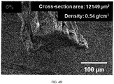
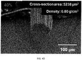
- the cross-section of the pristine specimen is very nonuniform due to the presence of large pores therein, whereas, in contrast, the cross section of the densified carbon nanotube fiber according to the present invention gradually takes on a shape having the curvature of a circle or a deformed circle as the stretching ratio thereof is increased.
- Carbon nanotube fiber having a linear density of about 6 tex was prepared using the aerogel direct spinning method.
- the carbon nanotube fiber was immersed in chlorosulfuric acid as an acid solution to swell the same, and then tension was gradually applied to the carbon nanotube fiber, thereby producing carbon nanotube fiber stretched to have a stretching ratio of 100%. It took a total of 3 minutes to execute these swelling and stretching processes.
- the stretched carbon nanotube fiber was coagulated by respectively applying acetone and a mixture including 85% by weight of diethyl ether and 15% by weight of oleum as a coagulation solution thereto, thereby producing coagulated carbon nanotube fibers. Thereafter, densified carbon nanotube fiber specimens were acquired by drying the coagulated carbon nanotube fibers.
- FIG. 5A is an image showing the result of analysis of the carbon nanotube fiber specimen using acetone as the coagulation solution
- FIG. 5B is an image showing the result of analysis of the carbon nanotube fiber specimen using diethyl ether and oleum as the coagulation solution.
- Carbon nanotube fiber having a linear density of about 6 tex was prepared using the aerogel direct spinning method.
- the carbon nanotube fiber was immersed in chlorosulfuric acid as an acid solution to swell the same, and then tension was gradually applied to the carbon nanotube fiber, thereby producing carbon nanotube fiber stretched to have a stretching ratio of 100%. It took a total of 3 minutes to execute these swelling and stretching processes.
- the stretched carbon nanotube fiber was coagulated by applying a coagulation solution including 85% by weight of diethyl ether and 15% by weight of oleum, thereby producing coagulated carbon nanotube fiber. Thereafter, densified carbon nanotube fiber specimens were acquired by drying the coagulated carbon nanotube fiber without applying tension thereto and while applying tension thereto.
- FIG. 6A is a graph showing the result of measurement of the specific strength of the carbon nanotube fiber specimen acquired through drying without applying tension thereto
- FIG. 6B is a graph showing the result of measurement of the specific strength of the carbon nanotube fiber specimen acquired through drying while applying tension thereto.
- the specific strength of the carbon nanotube fiber specimen acquired through drying without applying tension thereto is 1.39 N/tex
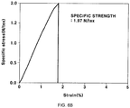
- the specific strength of the carbon nanotube fiber specimen acquired through drying while applying tension thereto is 1.97 N/tex. That is, it may be confirmed that, when tension is applied to the carbon nanotube fiber during the process of drying the carbon nanotube fiber, the specific strength of the densified carbon nanotube fiber is further improved.
- the present invention provides a method for mass-producing densified carbon nanotube fiber, thereby realizing commercialization of the carbon nanotube fiber.
- densified carbon nanotube fiber exhibiting both high strength typical of carbon fiber and high electrical conductivity close to that of metal may be produced.
Landscapes
- Engineering & Computer Science (AREA)
- Chemical & Material Sciences (AREA)
- Textile Engineering (AREA)
- Mechanical Engineering (AREA)
- Chemical Kinetics & Catalysis (AREA)
- Organic Chemistry (AREA)
- Nanotechnology (AREA)
- Materials Engineering (AREA)
- General Chemical & Material Sciences (AREA)
- Dispersion Chemistry (AREA)
- Inorganic Chemistry (AREA)
- Inorganic Fibers (AREA)
- Artificial Filaments (AREA)
- Carbon And Carbon Compounds (AREA)
Abstract
Description
- This application claims under 35 U.S.C. §119(a) the benefit of priority to Korean Patent Application No.
10-2020-0046900 filed on April 17, 2020 - The present disclosure relates to a method for mass-producing densified carbon nanotube fiber.
- In general, carbon nanotubes (CNTs) are a type of carbon allotrope that has a structure, in which graphene is rolled into a cylindrical shape, and has a diameter of several nm. CNTs are being actively researched in the academic world due to the excellent mechanical and physical properties thereof, and have tensile strength of dozens of GPa, electrical conductivity of 10,000,000 S/cm, and thermal conductivity of 6,600 W/mK.
- However, CNTs are short in actual length and thus have difficulty exhibiting the performance thereof when applied to a composite material, are difficult to handle directly, and have low dispersibility and thus the range of application thereof is limited. However, on entering the 2000s, technology for producing long fibers formed of CNTs has been developed, and thereby, the possibility of various applications for CNTs has been suggested.
- Carbon nanotube (CNT) fiber means yarn into which carbon nanotubes are physically woven, or fiber into which carbon nanotubes are chemically connected.
- Among methods for producing carbon nanotube fibers, there are broadly two methods which are suitable for mass-production. The first method is a direct spinning method. The direct spinning method was first announced at Cambridge University in 2004, and in this case, when carbon nanotubes are synthesized in vapor, the carbon nanotubes are directly drawn in the form of fiber, as if making cotton candy. A series of processes is performed continuously, fiber formation is carried out simultaneously with synthesis of the carbo nanotubes, and thus processing is simple. Further, a separate carbo nanotube dissolution process is not performed, and thus, carbon nanotube fiber formed of long carbon nanotubes can be produced. However, this method has limitations, such as a low density and a low degree of orientation.
- The second method is a wet spinning method. In the wet spinning method, carbon nanotube fiber is spun from a dope prepared by dispersing carbon nanotubes in a solvent. In general, carbon nanotubes are not easily dispersed in most solvents. At Rice University, the fact that chlorosulfonic acid (CSA) can thermodynamically dissolve carbon nanotubes and the solution acquired thereby has a liquid crystal phase was observed. Utilizing liquid crystalline dope, research team at Rice university could produce fibers having a high degree of orientation and high density were produced. However, with this technique, it is difficult to dissolve carbon nanotubes having a long length, and thus, it is difficult to produce carbon nanotube fiber formed of long carbon nanotubes.
- The inventors of the present invention suggested a novel method for manufacturing carbon nanotube fiber in which the advantages of the two methods are combined, in Korean Patent Registration No.
10-1972987 - However, the above method yields very desirable results on a laboratory scale carbon nanotube fiber, which is too thin for direct use in most industrial applications. From industrial view, meanwhile, direct spinning synthesizes carbon nanotubes suffers from low throughput because only single strand of fiber can be produced from a reactor. The production throughput (g min-1) of fiber per a direct-spinning reactor is evaluated as DL (g km-1) multiplied by the spinning rate (km min-1). The spinning rate cannot be easily increased beyond a certain level to yield continuous production of fiber, so leading manufacturers (e.g. Nanocomp Technologies, Inc.) increase the production throughput by producing CNTFs that have high linear density (4 tex - 10 tex). However, carbon nanotube fibers from mass production are two orders of magnitude thicker than the common fibers from lab-scale study, and have much different structural characteristics and properties, so the treatment conditions must be optimized to establish a practical densification protocol
- The above information disclosed in this Background section is only for enhancement of understanding of the background of the invention and therefore it may contain information that does not form the prior art that is already known in this country to a person of ordinary skill in the art.
- The present invention has been made in an effort to solve the above-described problems associated with the prior art, and it is an object of the present invention to provide a method for mass-producing densified carbon nanotube fiber.
- It is another object of the present invention to provide a method for producing densified carbon nanotube fiber having excellent physiochemical properties, such as specific strength and electrical conductivity, while having excellent mass-producibility and productivity.
- In one aspect, the present invention provides a method for producing densified carbon nanotube fiber, the method including preparing carbon nanotube fiber, swelling the carbon nanotube fiber by applying an acid solution thereto, and stretching the carbon nanotube fiber, coagulating the stretched carbon nanotube fiber so as to remove the acid solution present therein, drying the coagulated carbon nanotube fiber.
- In a preferred embodiment, in the preparing the carbon nanotube fiber, as-spun carbon nanotube fiber may be prepared by a direct spinning method.
- In another preferred embodiment, in the preparing the carbon nanotube fiber, carbon nanotube fiber having a linear density equal to or greater than 5 tex may be prepared.
- In still another preferred embodiment, in the swelling and stretching the carbon nanotube fiber, the carbon nanotube fiber may be immersed in the acid solution.
- In yet another preferred embodiment, the acid solution may be one selected from the group consisting of chlorosulfuric acid (HSO3Cl), fluorosulfuric acid (HSO3F), trifluoroacetic acid (CF3COOH), trifluoromethanesulfonic acid (CF3SO3H), fluoroantimonic acid (H2FSbF6), carborane acid, and combinations thereof.
- In still yet another preferred embodiment, in the swelling and stretching the carbon nanotube fiber, the carbon nanotube fiber may be immersed in the acid solution for 1 minute or longer.
- In a further preferred embodiment, in the swelling and stretching the carbon nanotube fiber, the carbon nanotube fiber is stretched to a stretching ratio greater than 0% but less than or equal to 200%.
- In another further preferred embodiment, in the coagulating the stretched carbon nanotube fiber, the stretched carbon nanotube fiber may be coagulated by applying a coagulation solution, selected from the group consisting of diethyl ether, fuming sulfuric acid (oleum) and a combination thereof, to the stretched carbon nanotube fiber.
- In still another further preferred embodiment, the coagulation solution mat include 50% by weight to 85% by weight of diethyl ether and 15% by weight to 50% by weight of oleum.
- In yet another further preferred embodiment, in the drying the coagulated carbon nanotube fiber, the coagulated carbon nanotube fiber may be dried while applying tension thereto.
- In another aspect, the present invention provides a densified carbon nanotube fiber configured to have a linear density equal to or greater than 3 tex, a density of 0.60 g/cm3 to 1.5 g/cm3, specific strength equal to or greater than 0.4 N/tex, tensile strength equal to or greater than 0.2 GPa, electrical conductivity equal to or greater than 0.3×10⁴ S/cm, and a cross-sectional area equal to or greater than 1,000 µm2.
- In a preferred embodiment, a cross-section of the densified carbon nanotube fiber may have a curvature of a circle or a deformed circle.
- In another preferred embodiment, on an assumption that a region of the densified carbon nanotube fiber corresponding to 50% of a depth thereof in a direction from a surface thereof to a center thereof based on a cross-section thereof is defined as a surface portion and a remaining region of the densified carbon nanotube fiber is defined as a central portion, a porosity difference between the surface portion and the central portion may be equal to or less than 10%.
- Other aspects and preferred embodiments of the invention are discussed infra. The above and other features of the invention are discussed infra.
- The above and other features of the present invention will now be described in detail with reference to certain exemplary embodiments thereof illustrated in the accompanying drawings which are given hereinbelow by way of illustration only, and thus are not limitative of the present invention, and wherein:
-
FIG. 1 is a flowchart schematically showing a method for producing densified carbon nanotube fiber according to the present invention; -
FIG. 2 is a conceptual view illustrating densification of carbon nanotube fiber according to one embodiment of the present invention; -
FIGs. 3A to 3F are graphs showing results of tests performed on respective specimens in Test Example 1 of the present invention, and more particularly,FIG. 3A is a graph showing results of measurement of linear densities of the specimens,FIG. 3B is a graph showing results of measurement of cross-sectional areas of the specimens,FIG. 3C is a graph showing results of densities of the specimens,FIG. 3D is a graph showing results of measurement of specific strengths of the specimens,FIG. 3E is a graph showing results of measurement of tensile strengths of the specimens, andFIG. 3F is a graph showing results of measurement of electrical conductivities of the specimens; -
FIGs. 4A to 4G are images showing results of scanning electron microscope analysis of the respective specimens in Test Example 1 of the present invention, and more particularly,FIG. 4A is an image showing the result of analysis of a pristine specimen, andFIGs. 4B to 4G are images showing the results of analysis of specimens having stretching ratios of 0%, 20%, 40%, 60%, 80% and 100%; -
FIGs. 5A and5B are images showing results of scanning electron microscope analysis of respective specimens in Test Example 2 of the present invention, and more particularly,FIG. 5A is an image showing the result of analysis of a carbon nanotube fiber specimen using acetone as a coagulation solution, andFIG. 5B is an image showing the result of analysis of a carbon nanotube fiber specimen using diethyl ether and fuming sulfuric acid as a coagulation solution; and -
FIGs. 6A and6B are graphs showing results of measurement of specific strengths of respective specimens in Test Example 3 of the present invention, and more particularly,FIG. 6A is a graph showing the result of measurement of the specific strength of a carbon nanotube fiber specimen dried without applying tension thereto, andFIG. 6B is a graph showing the result of measurement of the specific strength of a carbon nanotube fiber specimen dried while applying tension thereto. - It should be understood that the appended drawings are not necessarily to scale, presenting a somewhat simplified representation of various preferred features illustrative of the basic principles of the invention. The specific design features of the present invention as disclosed herein, including, for example, specific dimensions, orientations, locations, and shapes will be determined in part by the particular intended application and use environment.
- In the figures, reference numbers refer to the same or equivalent parts of the present invention throughout the several figures of the drawing.
- Hereinafter reference will be made in detail to various embodiments of the present invention, examples of which are illustrated in the accompanying drawings and described below. While the invention will be described in conjunction with exemplary embodiments, it will be understood that the present description is not intended to limit the invention to the exemplary embodiments. On the contrary, the invention is intended to cover not only the exemplary embodiments, but also various alternatives, modifications, equivalents and other embodiments that fall within the spirit and scope of the invention as defined by the appended claims.
- In the following description of the embodiments, the same elements are denoted by the same reference numerals even when they are depicted in different drawings. In the drawings, the dimensions of structures are exaggerated compared to the actual dimensions thereof, for clarity of description. In the following description of the embodiments, terms, such as "first" and "second", may be used to describe various elements but do not limit the elements. These terms are used only to distinguish one element from other elements. For example, a first element may be named a second element, and similarly, a second element may be named a first element, without departing from the scope and spirit of the invention. Singular expressions may encompass plural expressions, unless they have clearly different contextual meanings.
- In the following description of the embodiments, terms, such as "including" and "having", are to be interpreted as indicating the presence of characteristics, numbers, steps, operations, elements or parts stated in the description or combinations thereof, and do not exclude the presence of one or more other characteristics, numbers, steps, operations, elements, parts or combinations thereof, or possibility of adding the same. In addition, it will be understood that, when a part, such as a layer, a film, a region or a plate, is said to be "on" another part, the part may be located "directly on" the other part or other parts may be interposed between the two parts. In the same manner, it will be understood that, when a part, such as a layer, a film, a region or a plate, is said to be "under" another part, the part may be located "directly under" the other part or other parts may be interposed between the two parts.
- All numbers, values and/or expressions representing amounts of components, reaction conditions, polymer compositions and blends used in the description are approximations in which various uncertainties in measurement generated when these values are acquired from essentially different things are reflected and thus, it will be understood that they are to be understood to be modified by the term "about", unless stated otherwise. In addition, it will be understood that, if a numerical range is disclosed in the description, such a range includes all continuous values from a minimum value to a maximum value of the range, unless stated otherwise. Further, if such a range refers to integers, the range includes all integers from a minimum integer to a maximum integer, unless stated otherwise.
- In the following description of the embodiments, "carbon nanotube fiber" means a nano-structure in which carbon nanotubes are physically woven in the form of a spun yarn or in which carbon nanotubes are chemically connected in the form of a fiber.
- Further, "carbon nanotube fiber" conceptually includes single-wall carbon nanotube fiber, double-wall carbon nanotube fiber, and multi-wall carbon nanotube fiber.
- In addition, "fiber" refers to the form of a thin and long fiber, and conceptually includes filaments or yarns.
-
FIG. 1 is a flowchart schematically showing a method for producing densified carbon nanotube fiber according to the present invention. Referring to this figure, the method includes preparing carbon nanotube fiber (S10), swelling the carbon nanotube fiber by applying an acid solution thereto and stretching the carbon nanotube fiber (S20), coagulating the stretched carbon nanotube fiber so as to remove the acid solution present therein (S30), and drying the coagulated carbon nanotube fiber (S40). -
FIG. 2 is a conceptual view illustrating densification of carbon nanotube fiber according to one example of implementation of the present invention. Referring to this figure, carbon nanotubes are prepared formed by putting a carbon source, a catalyst and an activator, serving asraw materials 20 of carbon nanotubes, into an inlet provided at the upper end of afluidized bed reactor 10 and then moving theraw materials 20 downwards in thefluidized bed reactor 10, and are combined to formcarbon nanotube fiber 30. Thecarbon nanotube fiber 30 continuously passes through a swellingtub 40 containing an acid solution by rollers. Here, thecarbon nanotube fiber 30 is stretched by applying tension thereto using the rolling force of the rollers. Thereafter, the stretched carbon nanotube fiber passes through acoagulation tank 50 containing a coagulation solution, and thereby, densifiedcarbon nanotube fiber 60 is acquired. - Here, referring to
FIGs. 1 and 2 , the method for producing the densifiedcarbon nanotube fiber 60 according to the present invention will be described in more detail. - First, the
carbon nanotube fiber 30 is prepared (S10). Thecarbon nanotube fiber 30 may be as-spun by the direct spinning method. This may be performed using the above-describedfluidized bed reactor 10. For example, carbon nanotube aerogel may be formed by injecting a solution formed of a suitable combination of acetone, ferrocene, thiophene, etc. into thefluidized bed reactor 10, heated to a temperature of 1,000 °C or higher, at a designated speed, and be drawn into the form of fiber from thefluidized bed reactor 10 at a designated speed. - Particularly, the present invention is characterized in that
carbon nanotube fiber 30 having a linear density equal to or greater than 5 tex is used. The upper limit value of the linear density is not limited to a specific value. For example, the linear density of thecarbon nanotube fiber 30 may be equal to or less than 10 tex, equal to or less than 50 tex, or equal to or less than 100 tex. As such, when thecarbon nanotube fiber 30 having the linear density equal to or greater than 5 tex is used, mass-producibility and productivity may be greatly improved. For reference, carbon nanotube fiber having a linear density of about 0.05 tex is generally used in laboratory processes, whereas, in contrast,carbon nanotube fiber 30 having a linear density about 100 times higher than the linear density of the carbon nanotube fiber generally used in laboratory processes is used in the present invention. - The IG/ID ratio of the
carbon nanotube fiber 30 is not limited to a specific value and, for example, may be equal to or greater than 5, equal to or greater than 7, equal to or greater than 10, or equal to or greater than 15. Here, IG indicates the maximum peak intensity in the range of 1,560 cm-1 to 1,600 cm-1 in resonance Raman spectroscopy, and ID indicates the peak intensity in the range of 1,310 cm-1 to 1,350 cm-1 in resonance Raman spectroscopy. When the IG/ID ratio is equal to or greater than 5, swelling and stretching effects, which will be described below, increase. The upper limit value of the IG/ID ratio may be 500, 1,000 or 10,000, without being limited thereto. - When the carbon nanotubes take the form of fiber, the movement thereof is greatly limited. Therefore, it is difficult to remove voids which are nonuniformly disposed within the
carbon nanotube fiber 30. These voids cause degradation of physiochemical properties, such as specific strength, electrical conductivity, etc., of thecarbon nanotube fiber 30. Therefore, in the present invention, these voids are removed by densifying thecarbon nanotube fiber 30, and the process thereof will be described in detail below. - First, the
carbon nanotube fiber 30 is swollen by applying the acid solution thereto, and is stretched (S20). When thecarbon nanotube fiber 30 is immersed in the swellingtub 40 containing the acid solution, thecarbon nanotube fiber 30 is swollen by the acid solution. At this time, when tensile force is applied to thecarbon nanotube fiber 30 by a winding apparatus or the like, thecarbon nanotube fiber 30 is stretched. Consequently, the carbon nanotubes included in thecarbon nanotube fiber 30 are oriented and rearranged in the axial direction of thecarbon nanotube fiber 30. - The acid solution may be one selected from the group consisting of chlorosulfuric acid (HSO3Cl), fluorosulfuric acid (HSO3F), trifluoroacetic acid (CF3COOH), trifluoromethanesulfonic acid (CF3SO3H), fluoroantimonic acid (H2FSbF6), carborane acid, and combinations thereof.
- The
carbon nanotube fiber 30 may be immersed in the acid solution for 1 minute or longer. When the immersion time is less than 1 minute, thecarbon nanotube fiber 30 may not be sufficiently swollen. The upper limit value of the immersion time is not limited to a specific value, and, for example, may be 2 minutes or 5 minutes. When the immersion time is excessively long, productivity may be lowered and there is the possibility of damage to thecarbon nanotube fiber 30 due to the acid solution. - The stretching ratio of the
carbon nanotube fiber 30 may be greater than 0% but less than or equal to 200%, be greater than 0% but less than or equal to 100%, or be 40% to 100%. When the stretching ratio is within the above range, productivity and mass-producibility are the most excellent. When the stretching ratio is excessively great, there is the possibility of damage to thecarbon nanotube fiber 30. - Thereafter, the acid solution is removed by coagulating the stretched carbon nanotube fiber (S30). The stretched carbon nanotube fiber may pass through the
coagulation tank 50 containing the coagulation solution, thereby being coagulated. During the process of coagulating the stretched carbon nanotube fiber, the acid solution present therein is discharged. - Here, appropriate adjustment of the coagulation speed of the stretched carbon nanotube fiber is very important and, when the coagulation speed is excessively high, the acid solution may not be removed from the central portion of the carbon nanotube fiber. In this state, when the carbon nanotube fiber passes through a drying operation which will be described below, pores may be formed in the central portion of the carbon nanotube fiber, and thereby, the physiochemical properties, such as specific strength, electrical conductivity, etc., of the carbon nanotube fiber may be degraded.
- If the
carbon nanotube fiber 30 having a high linear density according to the present invention is used, the possibility of the above-described degradation of the physiochemical properties increases further. Therefore, the present invention is characterized in that thecarbon nanotube fiber 30 is coagulated using a coagulation solution including a specific combination, so as to remove the acid solution from the central portion and the surface portion of thecarbon nanotube fiber 30 with maximum uniformity. - Concretely, the coagulation solution may be one selected from the group consisting of diethyl ether, fuming sulfuric acid (oleum) and a combination thereof. Preferably, the coagulation solution may include 50% by weight to 85% by weight of diethyl ether and 15% by weight to 50% by weight of oleum.
- The densified carbon nanotube fiber may be acquired by drying the coagulated carbon nanotube fiber (S40). During the process of drying the coagulated carbon nanotube fiber, the acid solution present at a small amount in the carbon nanotube fiber is evaporated, and micropores are formed in the carbon nanotube fiber.
- Here, in the present invention, in order to reduce the size of the micropores, the carbon nanotube fiber is dried while applying tension thereto. Because the pores in the carbon nanotube fiber degrade the physiochemical properties, such as specific strength, electrical conductivity, etc., of the carbon nanotube fiber, as described above, degradation of the physiochemical properties of the carbon nanotube fiber may be prevented by reducing the size of the micropores.
- The magnitude of tension applied during the process of drying the carbon nanotube fiber is not limited to a specific value and, for example, the magnitude of tension may be applied so as to avoid stretching of the carbon nanotube fiber or so as to allow the carbon nanotube fiber to be stretched to a stretching ratio of 5% or lower.
- The drying conditions of the carbon nanotube fiber are not limited to specific conditions and, for example, the carbon nanotube fiber may be dried at a temperature of 150 °C to 200 °C.
- The densified carbon nanotube fiber produced by the above-described method may have a linear density equal to or greater than 3 tex. As described above, in the present invention,
carbon nanotube fiber 30 having a linear density equal to or greater than 5 tex is used, and thus, the linear density of the densified carbon nanotube fiber acquired as a product is very high. For reference, the upper limit value of the linear density of the densified carbon nanotube fiber is limited to a specific value and, for example, may be 30 tex, 15 tex, or 10 tex. - The cross-sectional area of the densified carbon nanotube fiber may be equal to or greater than 1,000 µm2 or 2,000 µm2. However, the cross-sectional area may be changed depending on the kind of the carbon nanotube tube fiber, the stretching ratio thereof, etc., and thus is not limited to the above numerical range.
- The density of the densified carbon nanotube fiber may be 0.60 g/cm3 to 1.5 g/cm3 or be 0.60 g/cm3 to 1.2 g/cm3.
- As such, the densified carbon nanotube fiber is highly and uniformly densified, and thus has excellent physiochemical properties, i.e., specific strength equal to or greater than 0.4 N/tex, tensile strength equal to or greater than 0.2 GPa and electrical conductivity equal to or greater than 0.3×10⁴ S/cm.
- Carbon nanotube fiber having a linear density of about 6 tex was prepared using an aerogel direct spinning method. The carbon nanotube fiber was immersed in chlorosulfuric acid as an acid solution to swell the same, and then tension was gradually applied to the carbon nanotube fiber, thereby producing carbon nanotube fibers stretched to have stretching ratios of 0% (i.e., in a specimen to which no tension is applied), 20%, 40%, 60%, 80% and 100%. It took a total of 3 minutes to execute these swelling and stretching processes. The respective stretched carbon nanotube fibers were coagulated by applying a coagulation solution including 85% by weight of diethyl ether and 15% by weight of oleum thereto. Densified carbon nanotube fiber specimens were acquired by drying the coagulated carbon nanotube fibers.
- The linear densities, cross-sectional areas, densities, specific strengths, tensile strengths and electrical conductivities of the respective densified carbon nanotube fiber specimens were measured. The results of measurement are shown in
FIGs. 3A to 3F . For reference, a pristine specimen is carbon nanotube fiber that has not been subjected to swelling, stretching or coagulating processes. - Referring to
FIG. 3A , it may be confirmed that the densified carbon nanotube fiber according to the present invention has a linear density of at least about 3 tex. - Referring to
FIG. 3B , it may be confirmed that the cross-sectional area of the densified carbon nanotube fiber according to the present invention is decreased as the stretching ratio thereof was increased, and thus, the cross-sectional area of the specimen having the stretching ratio of 100% is about 2,605 µm2. - Referring to
FIG. 3C , it may be confirmed that the density of the densified carbon nanotube fiber according to the present invention is increased as the stretching ratio thereof is increased, and thus, the density of the specimen having the stretching ratio of 100% is about 1.15 g/cm3. - Referring to
FIG. 3D , it may be confirmed that the specific strength of the densified carbon nanotube fiber according to the present invention is equal to or greater than 0.4 N/tex, and particularly, that the specific strength of the specimen having the stretching ratio of 100% is increased about 8 times or more compared to that of the pristine specimen. - Referring to
FIG. 3E , it may be confirmed that the tensile strength of the densified carbon nanotube fiber according to the present invention is equal to or greater than 0.2 GPa, and particularly, that the tensile strength of the specimen having the stretching ratio of 100% is improved about 30 times or more compared to that of the pristine specimen. - Referring to
FIG. 3F , it may be confirmed that the electrical conductivity of the densified carbon nanotube fiber according to the present invention is equal to or greater than 0.3×10⁴ S/cm, and particularly, that the electrical conductivity of the specimen having the stretching ratio of 100% is improved about 10 times or more compared to that of the pristine specimen. - Scanning electron microscope analysis of the cross-sections of the densified carbon nanotube fiber specimens was performed. The results of analysis are shown in
FIGs. 4A to 4G . For reference, the pristine specimen was carbon nanotube fiber that had not been subjected to swelling, stretching or coagulating processes. - Referring to
FIGs. 4A to 4G , it may be confirmed that the cross-section of the pristine specimen is very nonuniform due to the presence of large pores therein, whereas, in contrast, the cross section of the densified carbon nanotube fiber according to the present invention gradually takes on a shape having the curvature of a circle or a deformed circle as the stretching ratio thereof is increased. - Carbon nanotube fiber having a linear density of about 6 tex was prepared using the aerogel direct spinning method. The carbon nanotube fiber was immersed in chlorosulfuric acid as an acid solution to swell the same, and then tension was gradually applied to the carbon nanotube fiber, thereby producing carbon nanotube fiber stretched to have a stretching ratio of 100%. It took a total of 3 minutes to execute these swelling and stretching processes.
- The stretched carbon nanotube fiber was coagulated by respectively applying acetone and a mixture including 85% by weight of diethyl ether and 15% by weight of oleum as a coagulation solution thereto, thereby producing coagulated carbon nanotube fibers. Thereafter, densified carbon nanotube fiber specimens were acquired by drying the coagulated carbon nanotube fibers.
- Scanning electron microscope analysis of the densified carbon nanotube fiber specimens was performed. The results of analysis are shown in
FIGs. 5A and5B . Concretely,FIG. 5A is an image showing the result of analysis of the carbon nanotube fiber specimen using acetone as the coagulation solution, andFIG. 5B is an image showing the result of analysis of the carbon nanotube fiber specimen using diethyl ether and oleum as the coagulation solution. - Referring to
FIG. 5A , it may be confirmed that, when acetone was used as the coagulation solution, the coagulation speed of the carbon nanotube fiber was high and thus a lot of pores were formed. This means that the acid solution was not satisfactorily removed from the carbon nanotube fiber. - Referring to
FIG. 5B , it may be confirmed that, when diethyl ether and oleum were used as the coagulation solution, the number of pores was greatly reduced, the acid solution was uniformly removed from the surface portion and the central portion of the carbon nanotube fiber, and thus, the pores were uniformly distributed. - Carbon nanotube fiber having a linear density of about 6 tex was prepared using the aerogel direct spinning method. The carbon nanotube fiber was immersed in chlorosulfuric acid as an acid solution to swell the same, and then tension was gradually applied to the carbon nanotube fiber, thereby producing carbon nanotube fiber stretched to have a stretching ratio of 100%. It took a total of 3 minutes to execute these swelling and stretching processes. The stretched carbon nanotube fiber was coagulated by applying a coagulation solution including 85% by weight of diethyl ether and 15% by weight of oleum, thereby producing coagulated carbon nanotube fiber. Thereafter, densified carbon nanotube fiber specimens were acquired by drying the coagulated carbon nanotube fiber without applying tension thereto and while applying tension thereto.
- The specific strengths of the densified carbon nanotube fiber specimens acquired by the above-describe method were measured. The results of measurement are shown in
FIGs. 6A and6B . Concretely,FIG. 6A is a graph showing the result of measurement of the specific strength of the carbon nanotube fiber specimen acquired through drying without applying tension thereto, andFIG. 6B is a graph showing the result of measurement of the specific strength of the carbon nanotube fiber specimen acquired through drying while applying tension thereto. - Referring to
FIGs. 6A and6B , the specific strength of the carbon nanotube fiber specimen acquired through drying without applying tension thereto is 1.39 N/tex, and the specific strength of the carbon nanotube fiber specimen acquired through drying while applying tension thereto is 1.97 N/tex. That is, it may be confirmed that, when tension is applied to the carbon nanotube fiber during the process of drying the carbon nanotube fiber, the specific strength of the densified carbon nanotube fiber is further improved. - As is apparent from the above description, the present invention provides a method for mass-producing densified carbon nanotube fiber, thereby realizing commercialization of the carbon nanotube fiber.
- Further, through the method according to the present invention, densified carbon nanotube fiber exhibiting both high strength typical of carbon fiber and high electrical conductivity close to that of metal may be produced.
- The invention has been described in detail with reference to preferred embodiments thereof. However, it will be appreciated by those skilled in the art that changes may be made in these embodiments without departing from the principles and spirit of the invention, the scope of which is defined in the appended claims and their equivalents.
Claims (14)
- A method for producing densified carbon nanotube fiber, the method comprising:preparing carbon nanotube fiber;swelling the carbon nanotube fiber by applying an acid solution thereto, and stretching the carbon nanotube fiber;coagulating the stretched carbon nanotube fiber so as to remove the acid solution present therein; anddrying the coagulated carbon nanotube fiber.
- The method of claim 1, wherein, in the preparing the carbon nanotube fiber, as-spun carbon nanotube fiber is prepared by a direct spinning method.
- The method of claim 1 or 2, wherein, in the preparing the carbon nanotube fiber, carbon nanotube fiber having a linear density equal to or greater than 5 tex is prepared.
- The method of one of claims 1 to 3, wherein, in the swelling and stretching the carbon nanotube fiber, the carbon nanotube fiber is immersed in the acid solution.
- The method of one of claims 1 to 4, wherein the acid solution is one selected from the group consisting of chlorosulfuric acid (HSO3Cl), fluorosulfuric acid (HSO3F), trifluoroacetic acid (CF3COOH), trifluoromethanesulfonic acid (CF3SO3H), fluoroantimonic acid (H2FSbF6), carborane acid, and combinations thereof.
- The method of one of claims 1 to 5, wherein, in the swelling and stretching the carbon nanotube fiber, the carbon nanotube fiber is immersed in the acid solution for 1 minute or longer.
- The method of one of claims 1 to 6, wherein, in the swelling and stretching the carbon nanotube fiber, the carbon nanotube fiber is stretched to a stretching ratio greater than 0% but less than or equal to 200%.
- The method of one of claims 1 to 7, wherein, in the coagulating the stretched carbon nanotube fiber, the stretched carbon nanotube fiber is coagulated by applying a coagulation solution, selected from the group consisting of diethyl ether, fuming sulfuric acid (oleum) and a combination thereof, to the stretched carbon nanotube fiber.
- The method of claim 8, wherein the coagulation solution comprises 50% by weight to 85% by weight of diethyl ether and 15% by weight to 50% by weight of oleum.
- The method of one of claims 1 to 9, wherein, in the drying the coagulated carbon nanotube fiber, the coagulated carbon nanotube fiber is dried while applying tension thereto.
- A densified carbon nanotube fiber configured to have a linear density equal to or greater than 3 tex, a density of 0.60 g/cm3 to 1.5 g/cm3, specific strength equal to or greater than 0.4 N/tex, tensile strength equal to or greater than 0.2 GPa, and electrical conductivity equal to or greater than 0.3×10⁴ S/cm.
- The densified carbon nanotube fiber of claim 11, configured to have a cross-sectional area equal to or greater than 1,000 µm2.
- The densified carbon nanotube fiber of claim 11 or 12, wherein a cross-section of the densified carbon nanotube fiber has a curvature of a circle or a deformed circle.
- The densified carbon nanotube fiber of one of claims 11 to 13, wherein, on an assumption that a region of the densified carbon nanotube fiber corresponding to 50% of a depth thereof in a direction from a surface thereof to a center thereof based on a cross-section thereof is defined as a surface portion and a remaining region of the densified carbon nanotube fiber is defined as a central portion, a porosity difference between the surface portion and the central portion is equal to or less than 10%.
Applications Claiming Priority (1)
| Application Number | Priority Date | Filing Date | Title |
|---|---|---|---|
| KR1020200046900A KR102313612B1 (en) | 2020-04-17 | 2020-04-17 | Producing method for densified carbon nanotube fiber |
Publications (2)
| Publication Number | Publication Date |
|---|---|
| EP3896200A1 true EP3896200A1 (en) | 2021-10-20 |
| EP3896200B1 EP3896200B1 (en) | 2025-01-01 |
Family
ID=73597793
Family Applications (1)
| Application Number | Title | Priority Date | Filing Date |
|---|---|---|---|
| EP20209539.4A Active EP3896200B1 (en) | 2020-04-17 | 2020-11-24 | Method for producing densified carbon nanotube fiber |
Country Status (4)
| Country | Link |
|---|---|
| US (1) | US11897770B2 (en) |
| EP (1) | EP3896200B1 (en) |
| KR (1) | KR102313612B1 (en) |
| ES (1) | ES3018622T3 (en) |
Families Citing this family (7)
| Publication number | Priority date | Publication date | Assignee | Title |
|---|---|---|---|---|
| CN116623422B (en) * | 2022-02-10 | 2025-09-05 | 北京石墨烯研究院 | High-performance graphene/carbon nanotube composite fiber and preparation method thereof |
| CN114477147B (en) * | 2022-03-02 | 2023-05-16 | 中国科学院苏州纳米技术与纳米仿生研究所 | Post-treatment method for improving densification degree of carbon nano tube fibers |
| CN114672994B (en) * | 2022-04-19 | 2024-06-11 | 中国科学院苏州纳米技术与纳米仿生研究所 | A graphene-reinforced carbon nanotube composite fiber, and preparation method and device thereof |
| KR102809020B1 (en) * | 2022-08-12 | 2025-05-23 | 대주전자재료 주식회사 | Method and apparatus for synthesizing carbon nanotube |
| KR102841376B1 (en) | 2022-12-22 | 2025-08-01 | 한국과학기술연구원 | Manufacturing method of integrated carbon nanotube fibers and integrated carbon nanotube fibers |
| CN116281963B (en) * | 2023-03-24 | 2025-09-23 | 中国科学院苏州纳米技术与纳米仿生研究所 | A post-processing method for significantly improving the performance of carbon nanotube films and its application |
| CN116905215B (en) * | 2023-07-14 | 2025-07-29 | 中国科学院苏州纳米技术与纳米仿生研究所 | Carbon nanotube bundling body, preparation method and application thereof |
Citations (4)
| Publication number | Priority date | Publication date | Assignee | Title |
|---|---|---|---|---|
| WO2003004741A1 (en) * | 2001-07-06 | 2003-01-16 | William Marsh Rice University | Fibers of aligned single-wall carbon nanotubes and process for making the same |
| KR101726823B1 (en) * | 2015-11-25 | 2017-04-13 | 한국과학기술연구원 | Production method of high performance carbon nano tube/carbon composite fiber and cabon nanotube/carbon composite fiber thereby |
| US10246333B1 (en) * | 2017-12-11 | 2019-04-02 | Korea Institute Of Science And Technology | Method for continuous manufacture of cntf having high strength and high conductivity |
| EP3514110A1 (en) * | 2017-06-23 | 2019-07-24 | LG Chem, Ltd. | Method for enhancing tensile strength of carbon nanotube fiber aggregate |
Family Cites Families (9)
| Publication number | Priority date | Publication date | Assignee | Title |
|---|---|---|---|---|
| US20110110843A1 (en) * | 2007-10-29 | 2011-05-12 | William March Rice University | Neat carbon nanotube articles processed from super acid solutions and methods for production thereof |
| KR101537987B1 (en) * | 2010-08-11 | 2015-07-20 | 보드 오브 리전츠, 더 유니버시티 오브 텍사스 시스템 | Fabrication method of composite carbon nanotube fibers/yarns |
| CN103827364A (en) * | 2011-09-07 | 2014-05-28 | 帝人芳纶有限公司 | Carbon nanotubes fiber having low resistivity |
| WO2018138109A1 (en) | 2017-01-24 | 2018-08-02 | Conyar Bv | Process for forming shaped articles comprising carbon nanotubes |
| KR20190013343A (en) | 2017-08-01 | 2019-02-11 | 한국과학기술연구원 | Method of dissolving carbon nanotubes in acid using significantly increased solubility thereof by oxidation, and method of preparing carbon nanotube fibers with high-performance properties |
| KR102012429B1 (en) | 2018-02-09 | 2019-11-04 | 한국과학기술연구원 | Carbon nanotube fiber having improved mechanical and electrical properties and method of manufacturing the same |
| KR101956153B1 (en) * | 2018-10-04 | 2019-06-24 | 어썸레이 주식회사 | Method for Fabricating Yarn Comprising Carbon Nano Tube and Yarn Fabricated Thereby |
| WO2022154985A1 (en) * | 2021-01-13 | 2022-07-21 | ExxonMobil Technology and Engineering Company | Carbon nanotube constructs having a density gradient and methods for preparing same |
| US20230304193A1 (en) * | 2021-12-02 | 2023-09-28 | Rahul Franklin | Dry-jet wet-spinning of multifunctional carbon fibers |
-
2020
- 2020-04-17 KR KR1020200046900A patent/KR102313612B1/en active Active
- 2020-11-23 US US17/101,198 patent/US11897770B2/en active Active
- 2020-11-24 EP EP20209539.4A patent/EP3896200B1/en active Active
- 2020-11-24 ES ES20209539T patent/ES3018622T3/en active Active
Patent Citations (5)
| Publication number | Priority date | Publication date | Assignee | Title |
|---|---|---|---|---|
| WO2003004741A1 (en) * | 2001-07-06 | 2003-01-16 | William Marsh Rice University | Fibers of aligned single-wall carbon nanotubes and process for making the same |
| KR101726823B1 (en) * | 2015-11-25 | 2017-04-13 | 한국과학기술연구원 | Production method of high performance carbon nano tube/carbon composite fiber and cabon nanotube/carbon composite fiber thereby |
| EP3514110A1 (en) * | 2017-06-23 | 2019-07-24 | LG Chem, Ltd. | Method for enhancing tensile strength of carbon nanotube fiber aggregate |
| US10246333B1 (en) * | 2017-12-11 | 2019-04-02 | Korea Institute Of Science And Technology | Method for continuous manufacture of cntf having high strength and high conductivity |
| KR101972987B1 (en) | 2017-12-11 | 2019-04-29 | 한국과학기술연구원 | Method of manufacturing CNTF having high strength and high conductivity continuously |
Non-Patent Citations (2)
| Title |
|---|
| CHO HYUNJUNG ET AL: "Hierarchical structure of carbon nanotube fibers, and the change of structure during densification by wet stretching", CARBON, ELSEVIER OXFORD, GB, vol. 136, 25 April 2018 (2018-04-25), pages 409 - 416, XP085431477, ISSN: 0008-6223, DOI: 10.1016/J.CARBON.2018.04.071 * |
| LEE JAEGEUN ET AL: "Direct spinning and densification method for high-performance carbon nanotube fibers", NATURE COMMUNICATIONS, vol. 10, no. 1, 1 December 2019 (2019-12-01), XP055798074, Retrieved from the Internet <URL:https://www.nature.com/articles/s41467-019-10998-0.pdf> [retrieved on 20210422], DOI: 10.1038/s41467-019-10998-0 * |
Also Published As
| Publication number | Publication date |
|---|---|
| KR102313612B1 (en) | 2021-10-19 |
| EP3896200B1 (en) | 2025-01-01 |
| US11897770B2 (en) | 2024-02-13 |
| ES3018622T3 (en) | 2025-05-16 |
| US20210323826A1 (en) | 2021-10-21 |
Similar Documents
| Publication | Publication Date | Title |
|---|---|---|
| EP3896200B1 (en) | Method for producing densified carbon nanotube fiber | |
| JP5658567B2 (en) | Orderly aligned carbon nanotube article processed from superacid solution and method for producing the same | |
| Chou et al. | An assessment of the science and technology of carbon nanotube-based fibers and composites | |
| US10246333B1 (en) | Method for continuous manufacture of cntf having high strength and high conductivity | |
| CN101861416B (en) | Carbon fiber strand and process for producing the same | |
| EP1921183A1 (en) | Flame-resistant fiber, carbon fiber, and processes for the production of both | |
| Gao et al. | Effect of spinning speed on microstructures and mechanical properties of polyacrylonitrile fibers and carbon fibers | |
| KR102601181B1 (en) | Method for manufacturing molded articles containing carbon nanotubes | |
| CN109537110B (en) | A kind of preparation method of carbon nanotube fiber | |
| JP2009197365A (en) | Method for producing precursor fiber of carbon fiber, and method for producing the carbon fiber | |
| KR20120129040A (en) | Carbon nanotube fibers and method of preparing the same | |
| KR102322833B1 (en) | High performance and lightweight carbon nanotube fiber and preparing method thereof | |
| Sui et al. | Highly aligned polyacrylonitrile-based nano-scale carbon fibres with homogeneous structure and desirable properties | |
| CN116876114B (en) | A method for preparing high-strength and high-thermal-conductivity carbon nanotube fibers | |
| Gao et al. | New insight into structure-property correlation of polyacrylonitrile precursor fibers and resultant carbon fibers | |
| KR102377862B1 (en) | High density and high strength carbon nanotube fibers and evaluating method therof | |
| US11959193B2 (en) | Method of manufacturing an aramid and carbon-nanotube composite fiber | |
| KR102576931B1 (en) | Carbon nanotube fiber having improved property and preparing method thereof | |
| CN113089149A (en) | Carbon nanotube composite yarn and preparation method thereof | |
| CN116623422B (en) | High-performance graphene/carbon nanotube composite fiber and preparation method thereof | |
| CN113597484A (en) | Carbon fiber bundle and method for producing same | |
| JP6232814B2 (en) | Acrylic fiber manufacturing method | |
| KR20180081258A (en) | Method for manufacturing cnt fiber aggregates having improved strength between fibers | |
| JP4754855B2 (en) | Method for producing flame-resistant fiber, method for producing carbon fiber | |
| JP2006283225A (en) | Method for producing flame-proofed fiber and carbon fiber |
Legal Events
| Date | Code | Title | Description |
|---|---|---|---|
| PUAI | Public reference made under article 153(3) epc to a published international application that has entered the european phase |
Free format text: ORIGINAL CODE: 0009012 |
|
| STAA | Information on the status of an ep patent application or granted ep patent |
Free format text: STATUS: REQUEST FOR EXAMINATION WAS MADE |
|
| 17P | Request for examination filed |
Effective date: 20201213 |
|
| AK | Designated contracting states |
Kind code of ref document: A1 Designated state(s): AL AT BE BG CH CY CZ DE DK EE ES FI FR GB GR HR HU IE IS IT LI LT LU LV MC MK MT NL NO PL PT RO RS SE SI SK SM TR |
|
| B565 | Issuance of search results under rule 164(2) epc |
Effective date: 20210504 |
|
| RBV | Designated contracting states (corrected) |
Designated state(s): AL AT BE BG CH CY CZ DE DK EE ES FI FR GB GR HR HU IE IS IT LI LT LU LV MC MK MT NL NO PL PT RO RS SE SI SK SM TR |
|
| REG | Reference to a national code |
Ref country code: DE Ref legal event code: R079 Free format text: PREVIOUS MAIN CLASS: D01F0009120000 Ipc: D01F0011100000 Ref document number: 602020043980 Country of ref document: DE |
|
| GRAP | Despatch of communication of intention to grant a patent |
Free format text: ORIGINAL CODE: EPIDOSNIGR1 |
|
| STAA | Information on the status of an ep patent application or granted ep patent |
Free format text: STATUS: GRANT OF PATENT IS INTENDED |
|
| RIC1 | Information provided on ipc code assigned before grant |
Ipc: D06M 101/40 20060101ALI20240619BHEP Ipc: D06M 13/00 20060101ALI20240619BHEP Ipc: D01F 11/10 20060101AFI20240619BHEP |
|
| INTG | Intention to grant announced |
Effective date: 20240708 |
|
| GRAS | Grant fee paid |
Free format text: ORIGINAL CODE: EPIDOSNIGR3 |
|
| GRAA | (expected) grant |
Free format text: ORIGINAL CODE: 0009210 |
|
| STAA | Information on the status of an ep patent application or granted ep patent |
Free format text: STATUS: THE PATENT HAS BEEN GRANTED |
|
| AK | Designated contracting states |
Kind code of ref document: B1 Designated state(s): AL AT BE BG CH CY CZ DE DK EE ES FI FR GB GR HR HU IE IS IT LI LT LU LV MC MK MT NL NO PL PT RO RS SE SI SK SM TR |
|
| REG | Reference to a national code |
Ref country code: GB Ref legal event code: FG4D |
|
| REG | Reference to a national code |
Ref country code: CH Ref legal event code: EP |
|
| REG | Reference to a national code |
Ref country code: DE Ref legal event code: R096 Ref document number: 602020043980 Country of ref document: DE |
|
| REG | Reference to a national code |
Ref country code: IE Ref legal event code: FG4D |
|
| P01 | Opt-out of the competence of the unified patent court (upc) registered |
Free format text: CASE NUMBER: APP_52/2025 Effective date: 20250102 |
|
| REG | Reference to a national code |
Ref country code: LT Ref legal event code: MG9D |
|
| REG | Reference to a national code |
Ref country code: NL Ref legal event code: MP Effective date: 20250101 |
|
| REG | Reference to a national code |
Ref country code: ES Ref legal event code: FG2A Ref document number: 3018622 Country of ref document: ES Kind code of ref document: T3 Effective date: 20250516 |
|
| REG | Reference to a national code |
Ref country code: AT Ref legal event code: MK05 Ref document number: 1756321 Country of ref document: AT Kind code of ref document: T Effective date: 20250101 |
|
| PG25 | Lapsed in a contracting state [announced via postgrant information from national office to epo] |
Ref country code: NL Free format text: LAPSE BECAUSE OF FAILURE TO SUBMIT A TRANSLATION OF THE DESCRIPTION OR TO PAY THE FEE WITHIN THE PRESCRIBED TIME-LIMIT Effective date: 20250101 |
|
| PG25 | Lapsed in a contracting state [announced via postgrant information from national office to epo] |
Ref country code: FI Free format text: LAPSE BECAUSE OF FAILURE TO SUBMIT A TRANSLATION OF THE DESCRIPTION OR TO PAY THE FEE WITHIN THE PRESCRIBED TIME-LIMIT Effective date: 20250101 |
|
| PG25 | Lapsed in a contracting state [announced via postgrant information from national office to epo] |
Ref country code: PL Free format text: LAPSE BECAUSE OF FAILURE TO SUBMIT A TRANSLATION OF THE DESCRIPTION OR TO PAY THE FEE WITHIN THE PRESCRIBED TIME-LIMIT Effective date: 20250101 |
|
| PG25 | Lapsed in a contracting state [announced via postgrant information from national office to epo] |
Ref country code: IS Free format text: LAPSE BECAUSE OF FAILURE TO SUBMIT A TRANSLATION OF THE DESCRIPTION OR TO PAY THE FEE WITHIN THE PRESCRIBED TIME-LIMIT Effective date: 20250501 Ref country code: NO Free format text: LAPSE BECAUSE OF FAILURE TO SUBMIT A TRANSLATION OF THE DESCRIPTION OR TO PAY THE FEE WITHIN THE PRESCRIBED TIME-LIMIT Effective date: 20250401 |
|
| PG25 | Lapsed in a contracting state [announced via postgrant information from national office to epo] |
Ref country code: HR Free format text: LAPSE BECAUSE OF FAILURE TO SUBMIT A TRANSLATION OF THE DESCRIPTION OR TO PAY THE FEE WITHIN THE PRESCRIBED TIME-LIMIT Effective date: 20250101 |
|
| PG25 | Lapsed in a contracting state [announced via postgrant information from national office to epo] |
Ref country code: PT Free format text: LAPSE BECAUSE OF FAILURE TO SUBMIT A TRANSLATION OF THE DESCRIPTION OR TO PAY THE FEE WITHIN THE PRESCRIBED TIME-LIMIT Effective date: 20250502 Ref country code: LV Free format text: LAPSE BECAUSE OF FAILURE TO SUBMIT A TRANSLATION OF THE DESCRIPTION OR TO PAY THE FEE WITHIN THE PRESCRIBED TIME-LIMIT Effective date: 20250101 |
|
| PG25 | Lapsed in a contracting state [announced via postgrant information from national office to epo] |
Ref country code: BG Free format text: LAPSE BECAUSE OF FAILURE TO SUBMIT A TRANSLATION OF THE DESCRIPTION OR TO PAY THE FEE WITHIN THE PRESCRIBED TIME-LIMIT Effective date: 20250101 Ref country code: GR Free format text: LAPSE BECAUSE OF FAILURE TO SUBMIT A TRANSLATION OF THE DESCRIPTION OR TO PAY THE FEE WITHIN THE PRESCRIBED TIME-LIMIT Effective date: 20250402 |
|
| PG25 | Lapsed in a contracting state [announced via postgrant information from national office to epo] |
Ref country code: AT Free format text: LAPSE BECAUSE OF FAILURE TO SUBMIT A TRANSLATION OF THE DESCRIPTION OR TO PAY THE FEE WITHIN THE PRESCRIBED TIME-LIMIT Effective date: 20250101 |
|
| PG25 | Lapsed in a contracting state [announced via postgrant information from national office to epo] |
Ref country code: CZ Free format text: LAPSE BECAUSE OF FAILURE TO SUBMIT A TRANSLATION OF THE DESCRIPTION OR TO PAY THE FEE WITHIN THE PRESCRIBED TIME-LIMIT Effective date: 20250101 |
|
| PG25 | Lapsed in a contracting state [announced via postgrant information from national office to epo] |
Ref country code: SE Free format text: LAPSE BECAUSE OF FAILURE TO SUBMIT A TRANSLATION OF THE DESCRIPTION OR TO PAY THE FEE WITHIN THE PRESCRIBED TIME-LIMIT Effective date: 20250101 |
|
| REG | Reference to a national code |
Ref country code: DE Ref legal event code: R097 Ref document number: 602020043980 Country of ref document: DE |
|
| PG25 | Lapsed in a contracting state [announced via postgrant information from national office to epo] |
Ref country code: SM Free format text: LAPSE BECAUSE OF FAILURE TO SUBMIT A TRANSLATION OF THE DESCRIPTION OR TO PAY THE FEE WITHIN THE PRESCRIBED TIME-LIMIT Effective date: 20250101 |
|
| PG25 | Lapsed in a contracting state [announced via postgrant information from national office to epo] |
Ref country code: DK Free format text: LAPSE BECAUSE OF FAILURE TO SUBMIT A TRANSLATION OF THE DESCRIPTION OR TO PAY THE FEE WITHIN THE PRESCRIBED TIME-LIMIT Effective date: 20250101 |
|
| PG25 | Lapsed in a contracting state [announced via postgrant information from national office to epo] |
Ref country code: IT Free format text: LAPSE BECAUSE OF FAILURE TO SUBMIT A TRANSLATION OF THE DESCRIPTION OR TO PAY THE FEE WITHIN THE PRESCRIBED TIME-LIMIT Effective date: 20250101 |
|
| PG25 | Lapsed in a contracting state [announced via postgrant information from national office to epo] |
Ref country code: EE Free format text: LAPSE BECAUSE OF FAILURE TO SUBMIT A TRANSLATION OF THE DESCRIPTION OR TO PAY THE FEE WITHIN THE PRESCRIBED TIME-LIMIT Effective date: 20250101 |
|
| PG25 | Lapsed in a contracting state [announced via postgrant information from national office to epo] |
Ref country code: RO Free format text: LAPSE BECAUSE OF FAILURE TO SUBMIT A TRANSLATION OF THE DESCRIPTION OR TO PAY THE FEE WITHIN THE PRESCRIBED TIME-LIMIT Effective date: 20250101 |
|
| PG25 | Lapsed in a contracting state [announced via postgrant information from national office to epo] |
Ref country code: SK Free format text: LAPSE BECAUSE OF FAILURE TO SUBMIT A TRANSLATION OF THE DESCRIPTION OR TO PAY THE FEE WITHIN THE PRESCRIBED TIME-LIMIT Effective date: 20250101 |
|
| PLBE | No opposition filed within time limit |
Free format text: ORIGINAL CODE: 0009261 |
|
| STAA | Information on the status of an ep patent application or granted ep patent |
Free format text: STATUS: NO OPPOSITION FILED WITHIN TIME LIMIT |
|
| 26N | No opposition filed |
Effective date: 20251002 |
|
| PGFP | Annual fee paid to national office [announced via postgrant information from national office to epo] |
Ref country code: DE Payment date: 20251020 Year of fee payment: 6 |
|
| PGFP | Annual fee paid to national office [announced via postgrant information from national office to epo] |
Ref country code: GB Payment date: 20251023 Year of fee payment: 6 |
|
| PGFP | Annual fee paid to national office [announced via postgrant information from national office to epo] |
Ref country code: FR Payment date: 20251021 Year of fee payment: 6 |
|
| PGFP | Annual fee paid to national office [announced via postgrant information from national office to epo] |
Ref country code: ES Payment date: 20251215 Year of fee payment: 6 |