EP3895994A1 - Adaptive aircraft electrical power distribution system - Google Patents
Adaptive aircraft electrical power distribution system Download PDFInfo
- Publication number
- EP3895994A1 EP3895994A1 EP21167066.6A EP21167066A EP3895994A1 EP 3895994 A1 EP3895994 A1 EP 3895994A1 EP 21167066 A EP21167066 A EP 21167066A EP 3895994 A1 EP3895994 A1 EP 3895994A1
- Authority
- EP
- European Patent Office
- Prior art keywords
- power
- aircraft
- power source
- distribution system
- connector
- Prior art date
- Legal status (The legal status is an assumption and is not a legal conclusion. Google has not performed a legal analysis and makes no representation as to the accuracy of the status listed.)
- Granted
Links
Images


Classifications
-
- B—PERFORMING OPERATIONS; TRANSPORTING
- B64—AIRCRAFT; AVIATION; COSMONAUTICS
- B64D—EQUIPMENT FOR FITTING IN OR TO AIRCRAFT; FLIGHT SUITS; PARACHUTES; ARRANGEMENT OR MOUNTING OF POWER PLANTS OR PROPULSION TRANSMISSIONS IN AIRCRAFT
- B64D41/00—Power installations for auxiliary purposes
-
- B—PERFORMING OPERATIONS; TRANSPORTING
- B64—AIRCRAFT; AVIATION; COSMONAUTICS
- B64D—EQUIPMENT FOR FITTING IN OR TO AIRCRAFT; FLIGHT SUITS; PARACHUTES; ARRANGEMENT OR MOUNTING OF POWER PLANTS OR PROPULSION TRANSMISSIONS IN AIRCRAFT
- B64D27/00—Arrangement or mounting of power plants in aircraft; Aircraft characterised by the type or position of power plants
- B64D27/02—Aircraft characterised by the type or position of power plants
- B64D27/10—Aircraft characterised by the type or position of power plants of gas-turbine type
- B64D27/14—Aircraft characterised by the type or position of power plants of gas-turbine type within, or attached to, fuselages
-
- B—PERFORMING OPERATIONS; TRANSPORTING
- B64—AIRCRAFT; AVIATION; COSMONAUTICS
- B64F—GROUND OR AIRCRAFT-CARRIER-DECK INSTALLATIONS SPECIALLY ADAPTED FOR USE IN CONNECTION WITH AIRCRAFT; DESIGNING, MANUFACTURING, ASSEMBLING, CLEANING, MAINTAINING OR REPAIRING AIRCRAFT, NOT OTHERWISE PROVIDED FOR; HANDLING, TRANSPORTING, TESTING OR INSPECTING AIRCRAFT COMPONENTS, NOT OTHERWISE PROVIDED FOR
- B64F1/00—Ground or aircraft-carrier-deck installations
- B64F1/35—Ground or aircraft-carrier-deck installations for supplying electrical power to stationary aircraft
-
- F—MECHANICAL ENGINEERING; LIGHTING; HEATING; WEAPONS; BLASTING
- F02—COMBUSTION ENGINES; HOT-GAS OR COMBUSTION-PRODUCT ENGINE PLANTS
- F02C—GAS-TURBINE PLANTS; AIR INTAKES FOR JET-PROPULSION PLANTS; CONTROLLING FUEL SUPPLY IN AIR-BREATHING JET-PROPULSION PLANTS
- F02C7/00—Features, components parts, details or accessories, not provided for in, or of interest apart form groups F02C1/00 - F02C6/00; Air intakes for jet-propulsion plants
- F02C7/36—Power transmission arrangements between the different shafts of the gas turbine plant, or between the gas-turbine plant and the power user
-
- H—ELECTRICITY
- H02—GENERATION; CONVERSION OR DISTRIBUTION OF ELECTRIC POWER
- H02J—ELECTRIC POWER NETWORKS; CIRCUIT ARRANGEMENTS OR SYSTEMS FOR SUPPLYING OR DISTRIBUTING ELECTRIC POWER; SYSTEMS FOR STORING ELECTRIC ENERGY
- H02J13/00—Circuit arrangements for providing remote monitoring or remote control of equipment in a power distribution network
- H02J13/18—Circuit arrangements for providing remote monitoring or remote control of equipment in a power distribution network characterised by the remotely-controlled equipment, e.g. converters or transformers
- H02J13/34—Circuit arrangements for providing remote monitoring or remote control of equipment in a power distribution network characterised by the remotely-controlled equipment, e.g. converters or transformers the equipment being switches, relays or circuit breakers
-
- H—ELECTRICITY
- H02—GENERATION; CONVERSION OR DISTRIBUTION OF ELECTRIC POWER
- H02J—ELECTRIC POWER NETWORKS; CIRCUIT ARRANGEMENTS OR SYSTEMS FOR SUPPLYING OR DISTRIBUTING ELECTRIC POWER; SYSTEMS FOR STORING ELECTRIC ENERGY
- H02J3/00—Circuit arrangements for AC mains or AC distribution networks
- H02J3/007—Arrangements for selectively connecting one or more loads to one or more power sources or power lines
- H02J3/0075—Arrangements for selectively connecting one or more loads to one or more power sources or power lines for providing alternative feeding paths between load and source according to economic or energy efficiency considerations, e.g. economic dispatch
-
- H—ELECTRICITY
- H04—ELECTRIC COMMUNICATION TECHNIQUE
- H04W—WIRELESS COMMUNICATION NETWORKS
- H04W4/00—Services specially adapted for wireless communication networks; Facilities therefor
- H04W4/30—Services specially adapted for particular environments, situations or purposes
- H04W4/40—Services specially adapted for particular environments, situations or purposes for vehicles, e.g. vehicle-to-pedestrians [V2P]
- H04W4/48—Services specially adapted for particular environments, situations or purposes for vehicles, e.g. vehicle-to-pedestrians [V2P] for in-vehicle communication
-
- B—PERFORMING OPERATIONS; TRANSPORTING
- B64—AIRCRAFT; AVIATION; COSMONAUTICS
- B64D—EQUIPMENT FOR FITTING IN OR TO AIRCRAFT; FLIGHT SUITS; PARACHUTES; ARRANGEMENT OR MOUNTING OF POWER PLANTS OR PROPULSION TRANSMISSIONS IN AIRCRAFT
- B64D2221/00—Electric power distribution systems onboard aircraft
-
- H—ELECTRICITY
- H02—GENERATION; CONVERSION OR DISTRIBUTION OF ELECTRIC POWER
- H02J—ELECTRIC POWER NETWORKS; CIRCUIT ARRANGEMENTS OR SYSTEMS FOR SUPPLYING OR DISTRIBUTING ELECTRIC POWER; SYSTEMS FOR STORING ELECTRIC ENERGY
- H02J2105/00—Networks for supplying or distributing electric power characterised by their spatial reach or by the load
- H02J2105/30—Networks for supplying or distributing electric power characterised by their spatial reach or by the load the load networks being external to vehicles, i.e. exchanging power with vehicles
- H02J2105/32—Networks for supplying or distributing electric power characterised by their spatial reach or by the load the load networks being external to vehicles, i.e. exchanging power with vehicles for aircrafts
Definitions
- the present invention generally relates to aircraft electrical power generation, and more particularly relates to an adaptive aircraft electrical power distribution system that allows aircraft power sources to supply electrical power to loads that are external to the aircraft.
- auxiliary power sources such as, for example, one or more auxiliary power units (APUs) or one or more relatively smaller micro power units (mPUs).
- APUs and mPUs function, among other things, to generate and supply electrical power to the aircraft electrical load without having to run the main engines or connecting to an external ground power system. This reduces main engine wear, and concomitantly main engine maintenance, and also provides the added benefit of lower operational fuel costs.
- an adaptive aircraft electrical power distribution system includes an aircraft power source, a power connector, an aircraft power distribution bus, and a bidirectional power controller.
- the aircraft power source is disposed within an aircraft and is operable to generate and supply electrical power.
- the power connector is mounted on a fuselage of the aircraft.
- the aircraft power distribution bus is disposed within the aircraft and operable to distribute electrical power to an aircraft electrical load.
- the bidirectional power controller is mounted in the aircraft and is electrically coupled to the aircraft power source, the aircraft power connector, and the aircraft power distribution bus.
- the bidirectional power controller is configured to: sense when the aircraft power source is generating and supplying electrical power, sense when electrical power is being supplied to the power connector from an external power source, and selectively couple at least one of the aircraft power source or the power connector to the aircraft power distribution system.
- an adaptive aircraft electrical power distribution system in another embodiment, includes an engine generator, a power connector, an aircraft power distribution bus, and a bidirectional power controller.
- the engine generator is disposed within an aircraft and is operable to generate and supply electrical power.
- the power connector is mounted on a fuselage of the aircraft.
- the aircraft power distribution bus is disposed within the aircraft and is operable to distribute electrical power to an aircraft electrical load.
- the bidirectional power controller is mounted in the aircraft and is electrically coupled to the engine generator, the aircraft power connector, and the aircraft power distribution bus.
- the bidirectional power controller configured to: sense when the engine generator is generating and supplying electrical power, sense when electrical power is being supplied to the power connector from an external power source, electrically couple the engine generator to the power connector when (i) the engine generator is generating and supplying electrical power and (ii) electrical power is not being supplied to the power connector from an external power source, electrically couple the power connector to the aircraft power distribution system when (i) the engine generator is not generating and supplying electrical power and (ii) electrical power is being supplied to the power connector from an external power source, and electrically couple the power connector to the aircraft power distribution system when (i) the engine generator is generating and supplying electrical power and (ii) electrical power is simultaneously being supplied to the power connector from an external power source.
- an aircraft in yet another embodiment, includes a fuselage, an engine generator, a power connector, an aircraft power distribution system, and a bidirectional power controller.
- the engine generator is disposed within the fuselage and is operable to generate and supply electrical power.
- the power connector is mounted on the fuselage.
- the aircraft power distribution bus is disposed within the fuselage and is operable to distribute electrical power to an aircraft electrical load.
- the bidirectional power controller is mounted within the fuselage and is electrically coupled to the engine generator, the aircraft power connector, and the aircraft power distribution bus.
- the bidirectional power controller configured to: sense when the engine generator is generating and supplying electrical power, sense when electrical power is being supplied to the power connector from an external power source, electrically couple the engine generator to the power connector when (i) the engine generator is generating and supplying electrical power and (ii) electrical power is not being supplied to the power connector from an external power source, electrically couple the power connector to the aircraft power distribution system when (i) the engine generator is not generating and supplying electrical power and (ii) electrical power is being supplied to the power connector from an external power source, and electrically couple the power connector to the aircraft power distribution system when (i) the engine generator is generating and supplying electrical power and (ii) electrical power is simultaneously being supplied to the power connector from an external power source.
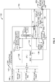
- FIG. 1 a functional block diagram of one embodiment of an adaptive aircraft electrical power distribution system 100 is depicted.
- the system 100 is disposed within an aircraft 102, and more specifically within the fuselage 104 of the aircraft 102, and includes an aircraft power source 106, a power connector 108, an aircraft power distribution bus 112, and a bidirectional power controller 114.
- the aircraft power source 106 is disposed within the fuselage and is operable to generate and supply electrical power.
- the aircraft power source 106 may be variously implemented. In the depicted embodiment it is implemented as an auxiliary power unit (APU) and its associated controls. In other embodiments, however, it may be implemented as any one of numerous other known power generators, such as a micro power unit (mPU).
- APU auxiliary power unit
- mPU micro power unit
- the power connector 108 is mounted on, and extends through, the fuselage 104 of the aircraft 102.
- the power connector 108 is adapted to connect to an external power cable 116.
- the power cable 116 may receive power from an external power source 202 (see FIG. 2 ) or supply power to one or more external power loads 302 (see FIG. 3 ).
- the aircraft power distribution bus 112 is operable to distribute electrical power to the aircraft electrical load based on aircraft system demand.
- the electrical load may fluctuate depending, for example, on which aircraft systems are being powered.
- aircraft power systems include, but are not limited to, the aircraft avionics 118, at least portions of the aircraft environmental control system 122, and other non-illustrated electrical systems.
- the aircraft power distribution bus 112 is a 28 VDC power distribution bus, which is standard for most aircraft electrical generation systems. However, the system described herein allows for both AC or DC buses, as needed or desired by the end application.
- the bidirectional power controller 114 is mounted in the aircraft 102 and is electrically coupled to the aircraft power source 106, the aircraft power connector 108, and the aircraft power distribution bus 112.
- the bidirectional power controller 114 is configured to sense when the aircraft power source 106 is generating and supplying electrical power, and sense when electrical power is being supplied to the power connector 108 from an external power source 202.
- the bidirectional power controller 114 is also configured to selectively couple at least one of the aircraft power source 106 or the power connector 108 to the aircraft power distribution system 112.
- the bidirectional controller 114 will electrically couple the power connector 108 to the aircraft power distribution system 112 when electrical power is being supplied to the power connector 108 from an external power source 202, and electrically couple the aircraft power source 106 to the aircraft power distribution system 112 when the aircraft power source 106 is generating and supplying electrical power. More specifically, as depicted in FIG. 2 , the bidirectional power controller 114 is configured to electrically couple the power connector 108 to the aircraft power distribution system 112 when electrical power is being supplied to the power connector 108 from an external power source 202 and the aircraft power source 106 is not generating and supplying electrical power. And, as depicted in FIG.
- the bidirectional power controller 114 is configured to electrically couple the aircraft power source 106 to the aircraft power distribution system 112 when the aircraft power source 106 is generating and supplying electrical power and electrical power is not being supplied to the power connector 108 from an external power source 202, but may instead be supplied to the one or more external power loads 302. Moreover, as FIG. 4 further depicts, the bidirectional power controller 114 is configured to electrically couple the power connector 108 to the aircraft power distribution system 112 when the aircraft power source 106 is generating and supplying electrical power and electrical power is simultaneously being supplied to the power connector 108 from an external power source 202.
- the bidirectional power controller 114 includes at least an aircraft power sensor 126, and external power sensor 128, a first controllable switch 132, a second controllable switch 134, and a processor 136, all of which are preferably (but not necessarily) disposed within a common housing 138.
- the aircraft power sensor 126 is electrically coupled to the output of the aircraft power source 106 and is in operable communication with the processor 136.
- the aircraft power sensor 126 is operable to sense when the aircraft power source 106 is generating and supplying electrical power and to at least supply a signal representative thereof to processor 136.
- the external power sensor 128 is electrically coupled to the power connector 108 and is also in operable communication with the processor 136.
- the external power sensor 128 is operable to sense when electrical power is being supplied to the power connector 108 from an external power source 202 and to at least supply a signal representative thereof to processor 136. It will be appreciated that the aircraft power sensor 126 and the external power sensor 128 may be implemented using any one of numerous known electrical power sensors, which may measure one or more electric power characteristics, such as voltage, current, and power. Some examples of known power sensors include Hall Effect sensors, inductive sensors, and direct measurement sensors, just to name a few.
- the first and second controllable switches 132, 134 are each in operable communication with the processor 136 and are each responsive to switch commands supplied from the processor 136 to move between an open position and a closed position. It will be appreciated that the first and second controllable switches 132, 134 may be implemented using anyone of numerous known command-responsive switching devices. Some non-limiting examples include any one of numerous types of semiconductor switches, optical switches, and electromechanical switches (e.g., relays).
- the first controllable switch 132 is electrically coupled between the aircraft power source 106 and the aircraft power distribution system 112, and the second controllable switch 134 is electrically coupled between the power connector 108 and the aircraft power distribution system 112.
- the first controllable switch 132 is in the open position
- the aircraft power source 106 is electrically disconnected from the aircraft power distribution system 112.
- the first controllable switch 132 is in the closed position
- the aircraft power source 106 is electrically coupled to the aircraft power distribution system 112.
- the second controllable switch 134 is in the open position
- the power connector 108 is electrically disconnected from the aircraft power distribution system 112.
- the second controllable switch 134 is in the closed position
- the power connector 108 is electrically coupled to the aircraft power distribution system 112.
- the processor 136 is in operable communication with the aircraft power sensor 126, the external power sensor 128, the first controllable switch 132, and the second controllable switch 134.
- the processor 136 is configured to be responsive to the signals supplied from the aircraft power sensor 126 and the external power sensor 128 to command either or both of the first and second controllable switches 132, 134 to the open or closed positions, to thereby the selectively couple either the aircraft power source 106 or the power connector 108 to the aircraft power distribution system 112.
- the processor 136 when the aircraft power sensor 126 and the external power sensor 128 supply signals indicating that electrical power is being supplied to the power connector 108 from an external power source 202 and that the aircraft power source 106 is not generating and supplying electrical power, the processor 136 will command the first controllable switch 132 to its open position and the second controllable switch 134 to its closed position ( FIG. 2 ).
- the processor 136 When the aircraft power sensor 126 and the external power sensor 128 supply signals indicating that the aircraft power source 106 is generating and supplying electrical power and electrical power is not being supplied to the power connector 108 from an external power source 202, the processor 136 will command the first controllable switch 132 to its closed position and the second controllable switch 134 to its closed position ( FIG. 3 ).
- the processor 136 will command the first controllable switch 132 to its open position and the second controllable switch 134 to its closed position ( FIG. 4 ). This latter functionality ensures that power from the external power source 202 takes priority over the aircraft power source 106 when both are supplying electrical power to the aircraft 102.
- the processor 136 may be any custom-made or commercially available processor, a central processing unit (CPU), a graphics processing unit (GPU), an application specific integrated circuit (ASIC), a field programmable gate array (FPGA), an auxiliary processor among several processors associated with the controller, a semiconductor-based microprocessor (in the form of a microchip or chip set), any combination thereof, or generally any device for executing instructions.
- CPU central processing unit
- GPU graphics processing unit
- ASIC application specific integrated circuit
- FPGA field programmable gate array
- auxiliary processor among several processors associated with the controller
- semiconductor-based microprocessor in the form of a microchip or chip set
- any combination thereof or generally any device for executing instructions.
- the depicted bidirectional power controller 114 also includes a load power sensor 140.
- This sensor 140 when included, is electrically coupled between the power connector 108 and the aircraft power distribution system 112, and is operable to sense the power being supplied from the aircraft power source 106 to any external power loads 302.
- the load power sensor 140 is also in operable communication with the processor 136 and supplies a signal to the processor 136 that is representative of the power being supplied to any external power loads 302.
- the system 100 may additionally include a control switch 142.
- the control switch 142 when included, is preferably disposed remotely from the bidirectional power controller 114, such as in the aircraft cockpit 144, and is in operable communication with the bidirectional power controller 114.
- the control switch 142 is movable to a first position, a second position, and a third position, which, at least in the depicted embodiment, correspond to Auto, External Power, and Internal Power, respectively.
- the bidirectional power controller 114 In the first (or Auto) position, the bidirectional power controller 114 automatically operates, as described above, to couple at least one of aircraft power source 106 or the power connector 108 to the aircraft power distribution system 112. In the second (or External Power) position, the bidirectional power controller 114 couples the power connector 108 to the aircraft power distribution system 112. In the third (or Internal Power) position, the bidirectional power controller 114 couples the aircraft power source 106 to the aircraft power distribution system 112.
- the bidirectional power controller 114 may also, in some embodiments, include a wireless transceiver 146.
- the wireless transceiver 146 may be part of the processor 136 itself, or it may be implemented as a separate device that is in operable communication with the processor 136. Regardless, it is operable to allow the bidirectional power controller 114 to wirelessly connect with, and wirelessly communicate with, a remote device 150, such as a smartphone, a tablet, or any one of numerous other hand-held devices.
- the wireless transceiver 146 could implement any one of numerous wireless communication protocols including, but not limited to, Bluetooth®, WiFi, or ZigBee.
- an application may be downloaded to the remote device 150 allowing the remoted device 150 to communicate with, and potentially control, the bidirectional power controller 114 via a graphical user interface (GUI).
- GUI graphical user interface
- the processor 136 and/or wireless transceiver 146 may also, in some embodiments, implement wireless communication encryption protocols and access control authentication methods.
- Some non-limiting examples of the authentication methods may include one or more of: a) something you have (e.g. smartphone), b) something you know (e.g. personal identification number, or PIN), and/or c) a personal characteristic of the user (e.g. biometric input such as a fingerprint). Including this capability could provide several benefits.
- Some benefits include preventing unauthorized access to the system 100, allowing the connected application to measure and report the power being provided, providing power use limitations to protect the batteries 124 and the aircraft power source 106 should the loads become a problem, and providing a record of power connector usage (e.g., date, time, power used, peak power used, length of connection, users of the power, etc.
- the app on the remote device 150 could allow the remote device 150 to transmit, via the wireless communication, various commands to the bidirectional power controller 114.
- the commands could include commanding the bidirectional power controller 114 to selectively couple at least one of the aircraft power source 106 or the power connector 108 to the aircraft power distribution system 112.
- the commands could also include, for example, commands to start and/or stop the aircraft power source 106.
- This functionality could be implemented without any user authentication, or with user authentication and confirmation that one or more safety-related cross-checks have been satisfied. Some examples of these cross-checks include, but are not limited to, aircraft weight on wheels detected, aircraft ground speed is zero knots, aircraft position (e.g. latitude and longitude) is within a predetermined "safe-distance" to the authorized remote device 150, and a safe-to-start interlock detected.
- the app on the remote device 150 may also, in some embodiments, enable the remote device 150 to scan and read a unique identifier, such as a bar-code, QR code, etc., on the power cable 116. Such functionality could be useful to control and record the power cable 116 being connected and help ensure that only approved power cables are connected to the power connector 108.
- the scanning and reading functionality of unique identifiers may also enable the ability to "gate" the power to the power connector 108 aircraft.
- the power cable 116 could be implemented with a "smart voltage convertor" to provide different voltages (e.g. 115 Vac, 28 Vdc, 5 Vdc, etc.).
- the information transmitted from the bidirectional power controller 114 to the remote device 150 could include various operational parameters that could be selectively viewed by flight crew or maintenance personnel.
- the operational parameters include: adaptive aircraft power distribution system status, adaptive aircraft power distribution system health, adaptive aircraft power distribution system faults, power supplied to external loads, power supplied to the aircraft power distribution system, peak power used by the aircraft power distribution system, time that electrical power is being supplied to the power connector from an external power source, time that the aircraft power source is generating and supplying electrical power, and any other historical power usage information that can be used for analytics or maintenance.
- the system described herein readily allows aircraft power sources to supply electrical power to loads that are external to the aircraft and for external power sources to supply electrical power to the aircraft. This allows aircraft electrical power sources to supply electrical power to, for example, ground mission systems, medical staging areas, troop encampments, and remote power cells, just to name a few.
- the system described herein also enables aircraft electrical power sources on one aircraft to supply electrical power to another aircraft that may have experienced a battery drain.
- Skilled artisans may implement the described functionality in varying ways for each particular application, but such implementation decisions should not be interpreted as causing a departure from the scope of the present invention.
- an embodiment of a system or a component may employ various integrated circuit components, e.g., memory elements, digital signal processing elements, logic elements, look-up tables, or the like, which may carry out a variety of functions under the control of one or more microprocessors or other control devices.
- integrated circuit components e.g., memory elements, digital signal processing elements, logic elements, look-up tables, or the like, which may carry out a variety of functions under the control of one or more microprocessors or other control devices.
- DSP digital signal processor
- ASIC application specific integrated circuit
- FPGA field programmable gate array
- a general-purpose processor may be a microprocessor, but in the alternative, the processor may be any conventional processor, controller, microcontroller, or state machine.
- a processor may also be implemented as a combination of computing devices, e.g., a combination of a DSP and a microprocessor, a plurality of microprocessors, one or more microprocessors in conjunction with a DSP core, or any other such configuration.
- a software module may reside in RAM memory, flash memory, ROM memory, EPROM memory, EEPROM memory, registers, hard disk, a removable disk, a CD-ROM, or any other form of storage medium known in the art.
- An exemplary storage medium is coupled to the processor such that the processor can read information from, and write information to, the storage medium.
- the storage medium may be integral to the processor.
- the processor and the storage medium may reside in an ASIC.
- an embodiment of a system or a component may employ various integrated circuit components, e.g., memory elements, digital signal processing elements, logic elements, look-up tables, or the like, which may carry out a variety of functions under the control of one or more microprocessors or other control devices.
- integrated circuit components e.g., memory elements, digital signal processing elements, logic elements, look-up tables, or the like, which may carry out a variety of functions under the control of one or more microprocessors or other control devices.
- various elements of the systems described herein are essentially the code segments or instructions that perform the various tasks.
- the program or code segments can be stored in a processor-readable medium or transmitted by a computer data signal embodied in a carrier wave over a transmission medium or communication path.
- the "computer-readable medium”, “processor-readable medium”, or “machine-readable medium” may include any medium that can store or transfer information. Examples of the processor-readable medium include an electronic circuit, a semiconductor memory device, a ROM, a flash memory, an erasable ROM (EROM), a floppy diskette, a CD-ROM, an optical disk, a hard disk, a fiber optic medium, a radio frequency (RF) link, or the like.
- RF radio frequency
- the computer data signal may include any signal that can propagate over a transmission medium such as electronic network channels, optical fibers, air, electromagnetic paths, or RF links.
- the code segments may be downloaded via computer networks such as the Internet, an intranet, a LAN, or the like.
- modules Some of the functional units described in this specification have been referred to as "modules" in order to more particularly emphasize their implementation independence.
- functionality referred to herein as a module may be implemented wholly, or partially, as a hardware circuit comprising custom VLSI circuits or gate arrays, off-the-shelf semiconductors such as logic chips, transistors, or other discrete components.
- a module may also be implemented in programmable hardware devices such as field programmable gate arrays, programmable array logic, programmable logic devices, or the like. Modules may also be implemented in software for execution by various types of processors.
- An identified module of executable code may, for instance, comprise one or more physical or logical modules of computer instructions that may, for instance, be organized as an object, procedure, or function.
- the executables of an identified module need not be physically located together, but may comprise disparate instructions stored in different locations that, when joined logically together, comprise the module and achieve the stated purpose for the module.
- a module of executable code may be a single instruction, or many instructions, and may even be distributed over several different code segments, among different programs, and across several memory devices.
- operational data may be embodied in any suitable form and organized within any suitable type of data structure. The operational data may be collected as a single data set, or may be distributed over different locations including over different storage devices, and may exist, at least partially, merely as electronic signals on a system or network.
Landscapes
- Engineering & Computer Science (AREA)
- Aviation & Aerospace Engineering (AREA)
- Mechanical Engineering (AREA)
- Chemical & Material Sciences (AREA)
- Combustion & Propulsion (AREA)
- Power Engineering (AREA)
- General Engineering & Computer Science (AREA)
- Computer Networks & Wireless Communication (AREA)
- Signal Processing (AREA)
- Remote Monitoring And Control Of Power-Distribution Networks (AREA)
Abstract
Description
- The present invention generally relates to aircraft electrical power generation, and more particularly relates to an adaptive aircraft electrical power distribution system that allows aircraft power sources to supply electrical power to loads that are external to the aircraft.
- Many aircraft, including both fixed-wing and rotary aircraft, are equipped with one or more auxiliary power sources such as, for example, one or more auxiliary power units (APUs) or one or more relatively smaller micro power units (mPUs). Most APUs and mPUs function, among other things, to generate and supply electrical power to the aircraft electrical load without having to run the main engines or connecting to an external ground power system. This reduces main engine wear, and concomitantly main engine maintenance, and also provides the added benefit of lower operational fuel costs.
- Currently, many aircraft are configured to allow external power source systems to supply electrical power to the aircraft. However, most aircraft are not configured to allow the APUs and/or mPUs to supply electrical power to loads that are external to the aircraft.
- Hence, there is a need for a system and method that allows aircraft power sources to supply electrical power to loads that are external to the aircraft and for external power sources to supply electrical power to the aircraft. This disclosure addresses at least this need.
- This summary is provided to describe select concepts in a simplified form that are further described in the Detailed Description. This summary is not intended to identify key or essential features of the claimed subject matter, nor is it intended to be used as an aid in determining the scope of the claimed subject matter.
- In one embodiment, an adaptive aircraft electrical power distribution system includes an aircraft power source, a power connector, an aircraft power distribution bus, and a bidirectional power controller. The aircraft power source is disposed within an aircraft and is operable to generate and supply electrical power. The power connector is mounted on a fuselage of the aircraft. The aircraft power distribution bus is disposed within the aircraft and operable to distribute electrical power to an aircraft electrical load. The bidirectional power controller is mounted in the aircraft and is electrically coupled to the aircraft power source, the aircraft power connector, and the aircraft power distribution bus. The bidirectional power controller is configured to: sense when the aircraft power source is generating and supplying electrical power, sense when electrical power is being supplied to the power connector from an external power source, and selectively couple at least one of the aircraft power source or the power connector to the aircraft power distribution system.
- In another embodiment, an adaptive aircraft electrical power distribution system includes an engine generator, a power connector, an aircraft power distribution bus, and a bidirectional power controller. The engine generator is disposed within an aircraft and is operable to generate and supply electrical power. The power connector is mounted on a fuselage of the aircraft. The aircraft power distribution bus is disposed within the aircraft and is operable to distribute electrical power to an aircraft electrical load. The bidirectional power controller is mounted in the aircraft and is electrically coupled to the engine generator, the aircraft power connector, and the aircraft power distribution bus. The bidirectional power controller configured to: sense when the engine generator is generating and supplying electrical power, sense when electrical power is being supplied to the power connector from an external power source, electrically couple the engine generator to the power connector when (i) the engine generator is generating and supplying electrical power and (ii) electrical power is not being supplied to the power connector from an external power source, electrically couple the power connector to the aircraft power distribution system when (i) the engine generator is not generating and supplying electrical power and (ii) electrical power is being supplied to the power connector from an external power source, and electrically couple the power connector to the aircraft power distribution system when (i) the engine generator is generating and supplying electrical power and (ii) electrical power is simultaneously being supplied to the power connector from an external power source.
- In yet another embodiment, an aircraft includes a fuselage, an engine generator, a power connector, an aircraft power distribution system, and a bidirectional power controller. The engine generator is disposed within the fuselage and is operable to generate and supply electrical power. The power connector is mounted on the fuselage. The aircraft power distribution bus is disposed within the fuselage and is operable to distribute electrical power to an aircraft electrical load. The bidirectional power controller is mounted within the fuselage and is electrically coupled to the engine generator, the aircraft power connector, and the aircraft power distribution bus. The bidirectional power controller configured to: sense when the engine generator is generating and supplying electrical power, sense when electrical power is being supplied to the power connector from an external power source, electrically couple the engine generator to the power connector when (i) the engine generator is generating and supplying electrical power and (ii) electrical power is not being supplied to the power connector from an external power source, electrically couple the power connector to the aircraft power distribution system when (i) the engine generator is not generating and supplying electrical power and (ii) electrical power is being supplied to the power connector from an external power source, and electrically couple the power connector to the aircraft power distribution system when (i) the engine generator is generating and supplying electrical power and (ii) electrical power is simultaneously being supplied to the power connector from an external power source.
- Furthermore, other desirable features and characteristics of the adaptive aircraft electrical power distribution system will become apparent from the subsequent detailed description and the appended claims, taken in conjunction with the accompanying drawings and the preceding background.
- The present invention will hereinafter be described in conjunction with the following drawing figures, wherein like numerals denote like elements, and wherein:
-
FIG. 1 depicts a functional block diagram of one embodiment of an adaptive aircraft electrical power distribution system; -
FIG. 2 depicts the system ofFIG. 1 in a first operational configuration; -
FIG. 3 depicts the system ofFIG. 1 in a second operational configuration; and -
FIG. 4 depicts the system ofFIG. 1 in a third operational configuration. - The following detailed description is merely exemplary in nature and is not intended to limit the invention or the application and uses of the invention. As used herein, the word "exemplary" means "serving as an example, instance, or illustration." Thus, any embodiment described herein as "exemplary" is not necessarily to be construed as preferred or advantageous over other embodiments. All of the embodiments described herein are exemplary embodiments provided to enable persons skilled in the art to make or use the invention and not to limit the scope of the invention which is defined by the claims. Furthermore, there is no intention to be bound by any expressed or implied theory presented in the preceding technical field, background, brief summary, or the following detailed description.
- Referring now to
FIG. 1 , a functional block diagram of one embodiment of an adaptive aircraft electricalpower distribution system 100 is depicted. Thesystem 100 is disposed within anaircraft 102, and more specifically within thefuselage 104 of theaircraft 102, and includes anaircraft power source 106, apower connector 108, an aircraftpower distribution bus 112, and abidirectional power controller 114. Theaircraft power source 106 is disposed within the fuselage and is operable to generate and supply electrical power. Theaircraft power source 106 may be variously implemented. In the depicted embodiment it is implemented as an auxiliary power unit (APU) and its associated controls. In other embodiments, however, it may be implemented as any one of numerous other known power generators, such as a micro power unit (mPU). - The
power connector 108 is mounted on, and extends through, thefuselage 104 of theaircraft 102. Thepower connector 108 is adapted to connect to anexternal power cable 116. As will be described momentarily, thepower cable 116 may receive power from an external power source 202 (seeFIG. 2 ) or supply power to one or more external power loads 302 (seeFIG. 3 ). - The aircraft
power distribution bus 112 is operable to distribute electrical power to the aircraft electrical load based on aircraft system demand. The electrical load may fluctuate depending, for example, on which aircraft systems are being powered. Some examples of aircraft power systems include, but are not limited to, theaircraft avionics 118, at least portions of the aircraftenvironmental control system 122, and other non-illustrated electrical systems. In the depicted embodiment, the aircraftpower distribution bus 112 is a 28 VDC power distribution bus, which is standard for most aircraft electrical generation systems. However, the system described herein allows for both AC or DC buses, as needed or desired by the end application. - The
bidirectional power controller 114 is mounted in theaircraft 102 and is electrically coupled to theaircraft power source 106, theaircraft power connector 108, and the aircraftpower distribution bus 112. Thebidirectional power controller 114 is configured to sense when theaircraft power source 106 is generating and supplying electrical power, and sense when electrical power is being supplied to thepower connector 108 from anexternal power source 202. Thebidirectional power controller 114 is also configured to selectively couple at least one of theaircraft power source 106 or thepower connector 108 to the aircraftpower distribution system 112. - Generally, though not always, the
bidirectional controller 114 will electrically couple thepower connector 108 to the aircraftpower distribution system 112 when electrical power is being supplied to thepower connector 108 from anexternal power source 202, and electrically couple theaircraft power source 106 to the aircraftpower distribution system 112 when theaircraft power source 106 is generating and supplying electrical power. More specifically, as depicted inFIG. 2 , thebidirectional power controller 114 is configured to electrically couple thepower connector 108 to the aircraftpower distribution system 112 when electrical power is being supplied to thepower connector 108 from anexternal power source 202 and theaircraft power source 106 is not generating and supplying electrical power. And, as depicted inFIG. 3 , thebidirectional power controller 114 is configured to electrically couple theaircraft power source 106 to the aircraftpower distribution system 112 when theaircraft power source 106 is generating and supplying electrical power and electrical power is not being supplied to thepower connector 108 from anexternal power source 202, but may instead be supplied to the one or moreexternal power loads 302. Moreover, asFIG. 4 further depicts, thebidirectional power controller 114 is configured to electrically couple thepower connector 108 to the aircraftpower distribution system 112 when theaircraft power source 106 is generating and supplying electrical power and electrical power is simultaneously being supplied to thepower connector 108 from anexternal power source 202. - To implement the above-described functionality, it is seen in
FIGS. 1-4 that thebidirectional power controller 114 includes at least anaircraft power sensor 126, andexternal power sensor 128, a firstcontrollable switch 132, a secondcontrollable switch 134, and aprocessor 136, all of which are preferably (but not necessarily) disposed within acommon housing 138. Theaircraft power sensor 126 is electrically coupled to the output of theaircraft power source 106 and is in operable communication with theprocessor 136. Theaircraft power sensor 126 is operable to sense when theaircraft power source 106 is generating and supplying electrical power and to at least supply a signal representative thereof toprocessor 136. Theexternal power sensor 128 is electrically coupled to thepower connector 108 and is also in operable communication with theprocessor 136. Theexternal power sensor 128 is operable to sense when electrical power is being supplied to thepower connector 108 from anexternal power source 202 and to at least supply a signal representative thereof toprocessor 136. It will be appreciated that theaircraft power sensor 126 and theexternal power sensor 128 may be implemented using any one of numerous known electrical power sensors, which may measure one or more electric power characteristics, such as voltage, current, and power. Some examples of known power sensors include Hall Effect sensors, inductive sensors, and direct measurement sensors, just to name a few. - The first and second
controllable switches processor 136 and are each responsive to switch commands supplied from theprocessor 136 to move between an open position and a closed position. It will be appreciated that the first and secondcontrollable switches - No matter the specific type of switches used, the first
controllable switch 132 is electrically coupled between theaircraft power source 106 and the aircraftpower distribution system 112, and the secondcontrollable switch 134 is electrically coupled between thepower connector 108 and the aircraftpower distribution system 112. Thus, when the firstcontrollable switch 132 is in the open position, theaircraft power source 106 is electrically disconnected from the aircraftpower distribution system 112. Conversely, when the firstcontrollable switch 132 is in the closed position, theaircraft power source 106 is electrically coupled to the aircraftpower distribution system 112. Similarly, when the secondcontrollable switch 134 is in the open position, thepower connector 108 is electrically disconnected from the aircraftpower distribution system 112. Conversely, when the secondcontrollable switch 134 is in the closed position, thepower connector 108 is electrically coupled to the aircraftpower distribution system 112. - The
processor 136, as noted above, is in operable communication with theaircraft power sensor 126, theexternal power sensor 128, the firstcontrollable switch 132, and the secondcontrollable switch 134. Theprocessor 136 is configured to be responsive to the signals supplied from theaircraft power sensor 126 and theexternal power sensor 128 to command either or both of the first and secondcontrollable switches aircraft power source 106 or thepower connector 108 to the aircraftpower distribution system 112. For example, and as noted above, when theaircraft power sensor 126 and theexternal power sensor 128 supply signals indicating that electrical power is being supplied to thepower connector 108 from anexternal power source 202 and that theaircraft power source 106 is not generating and supplying electrical power, theprocessor 136 will command the firstcontrollable switch 132 to its open position and the secondcontrollable switch 134 to its closed position (FIG. 2 ). When theaircraft power sensor 126 and theexternal power sensor 128 supply signals indicating that theaircraft power source 106 is generating and supplying electrical power and electrical power is not being supplied to thepower connector 108 from anexternal power source 202, theprocessor 136 will command the firstcontrollable switch 132 to its closed position and the secondcontrollable switch 134 to its closed position (FIG. 3 ). And when theaircraft power sensor 126 and theexternal power sensor 128 supply signals indicating that theaircraft power source 106 is generating and supplying electrical power and electrical power is simultaneously being supplied to thepower connector 108 from anexternal power source 202, theprocessor 136 will command the firstcontrollable switch 132 to its open position and the secondcontrollable switch 134 to its closed position (FIG. 4 ). This latter functionality ensures that power from theexternal power source 202 takes priority over theaircraft power source 106 when both are supplying electrical power to theaircraft 102. - It will be appreciated that the
processor 136 may be any custom-made or commercially available processor, a central processing unit (CPU), a graphics processing unit (GPU), an application specific integrated circuit (ASIC), a field programmable gate array (FPGA), an auxiliary processor among several processors associated with the controller, a semiconductor-based microprocessor (in the form of a microchip or chip set), any combination thereof, or generally any device for executing instructions. - Before proceeding further, it is noted that the depicted
bidirectional power controller 114 also includes aload power sensor 140. Thissensor 140, when included, is electrically coupled between thepower connector 108 and the aircraftpower distribution system 112, and is operable to sense the power being supplied from theaircraft power source 106 to any external power loads 302. Theload power sensor 140 is also in operable communication with theprocessor 136 and supplies a signal to theprocessor 136 that is representative of the power being supplied to any external power loads 302. - The functionality of the
bidirectional power controller 114 has thus far been described as implementing automatic control. It may be desirable, however, to provide thesystem 100 with manual control. In such cases, for example, thesystem 100 may additionally include acontrol switch 142. Thecontrol switch 142, when included, is preferably disposed remotely from thebidirectional power controller 114, such as in theaircraft cockpit 144, and is in operable communication with thebidirectional power controller 114. Thecontrol switch 142 is movable to a first position, a second position, and a third position, which, at least in the depicted embodiment, correspond to Auto, External Power, and Internal Power, respectively. - In the first (or Auto) position, the
bidirectional power controller 114 automatically operates, as described above, to couple at least one ofaircraft power source 106 or thepower connector 108 to the aircraftpower distribution system 112. In the second (or External Power) position, thebidirectional power controller 114 couples thepower connector 108 to the aircraftpower distribution system 112. In the third (or Internal Power) position, thebidirectional power controller 114 couples theaircraft power source 106 to the aircraftpower distribution system 112. - The
bidirectional power controller 114 may also, in some embodiments, include awireless transceiver 146. Thewireless transceiver 146 may be part of theprocessor 136 itself, or it may be implemented as a separate device that is in operable communication with theprocessor 136. Regardless, it is operable to allow thebidirectional power controller 114 to wirelessly connect with, and wirelessly communicate with, aremote device 150, such as a smartphone, a tablet, or any one of numerous other hand-held devices. Thewireless transceiver 146 could implement any one of numerous wireless communication protocols including, but not limited to, Bluetooth®, WiFi, or ZigBee. - In some embodiments, an application (or "app") may be downloaded to the
remote device 150 allowing theremoted device 150 to communicate with, and potentially control, thebidirectional power controller 114 via a graphical user interface (GUI). Theprocessor 136 and/orwireless transceiver 146 may also, in some embodiments, implement wireless communication encryption protocols and access control authentication methods. Some non-limiting examples of the authentication methods may include one or more of: a) something you have (e.g. smartphone), b) something you know (e.g. personal identification number, or PIN), and/or c) a personal characteristic of the user (e.g. biometric input such as a fingerprint). Including this capability could provide several benefits. Some benefits include preventing unauthorized access to thesystem 100, allowing the connected application to measure and report the power being provided, providing power use limitations to protect thebatteries 124 and theaircraft power source 106 should the loads become a problem, and providing a record of power connector usage (e.g., date, time, power used, peak power used, length of connection, users of the power, etc. - In still other embodiments, the app on the
remote device 150 could allow theremote device 150 to transmit, via the wireless communication, various commands to thebidirectional power controller 114. The commands could include commanding thebidirectional power controller 114 to selectively couple at least one of theaircraft power source 106 or thepower connector 108 to the aircraftpower distribution system 112. The commands could also include, for example, commands to start and/or stop theaircraft power source 106. This functionality could be implemented without any user authentication, or with user authentication and confirmation that one or more safety-related cross-checks have been satisfied. Some examples of these cross-checks include, but are not limited to, aircraft weight on wheels detected, aircraft ground speed is zero knots, aircraft position (e.g. latitude and longitude) is within a predetermined "safe-distance" to the authorizedremote device 150, and a safe-to-start interlock detected. - The app on the
remote device 150 may also, in some embodiments, enable theremote device 150 to scan and read a unique identifier, such as a bar-code, QR code, etc., on thepower cable 116. Such functionality could be useful to control and record thepower cable 116 being connected and help ensure that only approved power cables are connected to thepower connector 108. The scanning and reading functionality of unique identifiers may also enable the ability to "gate" the power to thepower connector 108 aircraft. In some embodiments, thepower cable 116 could be implemented with a "smart voltage convertor" to provide different voltages (e.g. 115 Vac, 28 Vdc, 5 Vdc, etc.). - In still other embodiments, the information transmitted from the
bidirectional power controller 114 to theremote device 150 could include various operational parameters that could be selectively viewed by flight crew or maintenance personnel. Some non-limiting examples of the operational parameters include: adaptive aircraft power distribution system status, adaptive aircraft power distribution system health, adaptive aircraft power distribution system faults, power supplied to external loads, power supplied to the aircraft power distribution system, peak power used by the aircraft power distribution system, time that electrical power is being supplied to the power connector from an external power source, time that the aircraft power source is generating and supplying electrical power, and any other historical power usage information that can be used for analytics or maintenance. - The system described herein readily allows aircraft power sources to supply electrical power to loads that are external to the aircraft and for external power sources to supply electrical power to the aircraft. This allows aircraft electrical power sources to supply electrical power to, for example, ground mission systems, medical staging areas, troop encampments, and remote power cells, just to name a few. The system described herein also enables aircraft electrical power sources on one aircraft to supply electrical power to another aircraft that may have experienced a battery drain.
- Those of skill in the art will appreciate that the various illustrative logical blocks, modules, circuits, and algorithm steps described in connection with the embodiments disclosed herein may be implemented as electronic hardware, computer software, or combinations of both. Some of the embodiments and implementations are described above in terms of functional and/or logical block components (or modules) and various processing steps. However, it should be appreciated that such block components (or modules) may be realized by any number of hardware, software, and/or firmware components configured to perform the specified functions. To clearly illustrate this interchangeability of hardware and software, various illustrative components, blocks, modules, circuits, and steps have been described above generally in terms of their functionality. Whether such functionality is implemented as hardware or software depends upon the particular application and design constraints imposed on the overall system. Skilled artisans may implement the described functionality in varying ways for each particular application, but such implementation decisions should not be interpreted as causing a departure from the scope of the present invention. For example, an embodiment of a system or a component may employ various integrated circuit components, e.g., memory elements, digital signal processing elements, logic elements, look-up tables, or the like, which may carry out a variety of functions under the control of one or more microprocessors or other control devices. In addition, those skilled in the art will appreciate that embodiments described herein are merely exemplary implementations.
- The various illustrative logical blocks, modules, and circuits described in connection with the embodiments disclosed herein may be implemented or performed with a general purpose processor, a digital signal processor (DSP), an application specific integrated circuit (ASIC), a field programmable gate array (FPGA) or other programmable logic device, discrete gate or transistor logic, discrete hardware components, or any combination thereof designed to perform the functions described herein. A general-purpose processor may be a microprocessor, but in the alternative, the processor may be any conventional processor, controller, microcontroller, or state machine. A processor may also be implemented as a combination of computing devices, e.g., a combination of a DSP and a microprocessor, a plurality of microprocessors, one or more microprocessors in conjunction with a DSP core, or any other such configuration.
- The steps of a method or algorithm described in connection with the embodiments disclosed herein may be embodied directly in hardware, in a software module executed by a processor, or in a combination of the two. A software module may reside in RAM memory, flash memory, ROM memory, EPROM memory, EEPROM memory, registers, hard disk, a removable disk, a CD-ROM, or any other form of storage medium known in the art. An exemplary storage medium is coupled to the processor such that the processor can read information from, and write information to, the storage medium. In the alternative, the storage medium may be integral to the processor. The processor and the storage medium may reside in an ASIC.
- Techniques and technologies may be described herein in terms of functional and/or logical block components, and with reference to symbolic representations of operations, processing tasks, and functions that may be performed by various computing components or devices. Such operations, tasks, and functions are sometimes referred to as being computer-executed, computerized, software-implemented, or computer-implemented. In practice, one or more processor devices can carry out the described operations, tasks, and functions by manipulating electrical signals representing data bits at memory locations in the system memory, as well as other processing of signals. The memory locations where data bits are maintained are physical locations that have particular electrical, magnetic, optical, or organic properties corresponding to the data bits. It should be appreciated that the various block components shown in the figures may be realized by any number of hardware, software, and/or firmware components configured to perform the specified functions. For example, an embodiment of a system or a component may employ various integrated circuit components, e.g., memory elements, digital signal processing elements, logic elements, look-up tables, or the like, which may carry out a variety of functions under the control of one or more microprocessors or other control devices.
- When implemented in software or firmware, various elements of the systems described herein are essentially the code segments or instructions that perform the various tasks. The program or code segments can be stored in a processor-readable medium or transmitted by a computer data signal embodied in a carrier wave over a transmission medium or communication path. The "computer-readable medium", "processor-readable medium", or "machine-readable medium" may include any medium that can store or transfer information. Examples of the processor-readable medium include an electronic circuit, a semiconductor memory device, a ROM, a flash memory, an erasable ROM (EROM), a floppy diskette, a CD-ROM, an optical disk, a hard disk, a fiber optic medium, a radio frequency (RF) link, or the like. The computer data signal may include any signal that can propagate over a transmission medium such as electronic network channels, optical fibers, air, electromagnetic paths, or RF links. The code segments may be downloaded via computer networks such as the Internet, an intranet, a LAN, or the like.
- Some of the functional units described in this specification have been referred to as "modules" in order to more particularly emphasize their implementation independence. For example, functionality referred to herein as a module may be implemented wholly, or partially, as a hardware circuit comprising custom VLSI circuits or gate arrays, off-the-shelf semiconductors such as logic chips, transistors, or other discrete components. A module may also be implemented in programmable hardware devices such as field programmable gate arrays, programmable array logic, programmable logic devices, or the like. Modules may also be implemented in software for execution by various types of processors. An identified module of executable code may, for instance, comprise one or more physical or logical modules of computer instructions that may, for instance, be organized as an object, procedure, or function. Nevertheless, the executables of an identified module need not be physically located together, but may comprise disparate instructions stored in different locations that, when joined logically together, comprise the module and achieve the stated purpose for the module. Indeed, a module of executable code may be a single instruction, or many instructions, and may even be distributed over several different code segments, among different programs, and across several memory devices. Similarly, operational data may be embodied in any suitable form and organized within any suitable type of data structure. The operational data may be collected as a single data set, or may be distributed over different locations including over different storage devices, and may exist, at least partially, merely as electronic signals on a system or network.
- In this document, relational terms such as first and second, and the like may be used solely to distinguish one entity or action from another entity or action without necessarily requiring or implying any actual such relationship or order between such entities or actions. Numerical ordinals such as "first," "second," "third," etc. simply denote different singles of a plurality and do not imply any order or sequence unless specifically defined by the claim language. The sequence of the text in any of the claims does not imply that process steps must be performed in a temporal or logical order according to such sequence unless it is specifically defined by the language of the claim. The process steps may be interchanged in any order without departing from the scope of the invention as long as such an interchange does not contradict the claim language and is not logically nonsensical.
- Furthermore, depending on the context, words such as "connect" or "coupled to" used in describing a relationship between different elements do not imply that a direct physical connection must be made between these elements. For example, two elements may be connected to each other physically, electronically, logically, or in any other manner, through one or more additional elements.
- While at least one exemplary embodiment has been presented in the foregoing detailed description of the invention, it should be appreciated that a vast number of variations exist. It should also be appreciated that the exemplary embodiment or exemplary embodiments are only examples, and are not intended to limit the scope, applicability, or configuration of the invention in any way. Rather, the foregoing detailed description will provide those skilled in the art with a convenient road map for implementing an exemplary embodiment of the invention. It being understood that various changes may be made in the function and arrangement of elements described in an exemplary embodiment without departing from the scope of the invention as set forth in the appended claims.
Claims (12)
- An adaptive aircraft electrical power distribution system, comprising:an aircraft power source disposed within an aircraft, the aircraft power source operable to generate and supply electrical power;a power connector mounted on a fuselage of the aircraft;an aircraft power distribution bus disposed within the aircraft and operable to distribute electrical power to an aircraft electrical load; anda bidirectional power controller mounted in the aircraft and electrically coupled to the aircraft power source, the aircraft power connector, and the aircraft power distribution bus, the bidirectional power controller configured to:sense when the aircraft power source is generating and supplying electrical power,sense when electrical power is being supplied to the power connector from an external power source, andselectively couple at least one of the aircraft power source or the power connector to the aircraft power distribution system.
- The system of claim 1, wherein the bidirectional power controller is configured to:electrically couple the power connector to the aircraft power distribution system when electrical power is being supplied to the power connector from an external power source; andelectrically couple the aircraft power source to the aircraft power distribution system when the aircraft power source is generating and supplying electrical power.
- The system of claim 2, wherein the bidirectional power controller is further configured to electrically couple the aircraft power source to the power connector when (i) the aircraft power source is generating and supplying electrical power and (ii) electrical power is not being supplied to the power connector from an external power source.
- The system of claim 2, wherein the bidirectional power controller is further configured to electrically couple the power connector to the aircraft power distribution system when (i) the aircraft power source is generating and supplying electrical power and (ii) electrical power is simultaneously being supplied to the power connector from an external power source.
- The system of claim 1, further comprising:a control switch disposed remotely from, and in operable communication with, the bidirectional power controller, the control switch movable to a first position, a second position, and a third position,wherein:in the first position, the bidirectional power controller automatically couples at least one of the aircraft power source or the power connector to the aircraft power distribution system,in the second position, the bidirectional power controller couples the power connector to the aircraft power distribution system, andin the third position, the bidirectional power controller couples the aircraft power source to the aircraft power distribution system.
- The system of claim 5, wherein the control switch is disposed in a cockpit of the aircraft.
- The system of claim 1, wherein the bidirectional power controller includes a wireless transceiver that is operable to wirelessly connect with a remote device to thereby wirelessly communicate with the remote device.
- The system of claim 7, wherein the bidirectional power controller is further configured, upon wirelessly connecting with the remote device, to transmit information to, and receive information from, the remote device.
- The system of claim 8, wherein the information transmitted from the bidirectional power controller to the remote device includes one or more of: adaptive aircraft power distribution system status, adaptive aircraft power distribution system health, adaptive aircraft power distribution system faults, power supplied to external loads, power supplied to the aircraft power distribution system, peak power used by the aircraft power distribution system, time that electrical power is being supplied to the power connector from an external power source, and time that the aircraft power source is generating and supplying electrical power.
- The system of claim 8, wherein
the information transmitted from the remote device to the bidirectional power controller includes at least one or more commands; and
the bidirectional power controller is responsive to the one or more commands to selectively couple at least one of the aircraft power source or the power connector to the aircraft power distribution system. - The system of claim 8, wherein the remote device is further configured to at least selectively implement a cable scanning function that verifies the cable meets at least one criterion.
- The system of claim 1, wherein the aircraft power source is a gas turbine engine generator.
Applications Claiming Priority (1)
| Application Number | Priority Date | Filing Date | Title |
|---|---|---|---|
| US16/850,518 US11448136B2 (en) | 2020-04-16 | 2020-04-16 | Adaptive aircraft electrical power distribution system |
Publications (2)
| Publication Number | Publication Date |
|---|---|
| EP3895994A1 true EP3895994A1 (en) | 2021-10-20 |
| EP3895994B1 EP3895994B1 (en) | 2024-09-11 |
Family
ID=75426399
Family Applications (1)
| Application Number | Title | Priority Date | Filing Date |
|---|---|---|---|
| EP21167066.6A Active EP3895994B1 (en) | 2020-04-16 | 2021-04-06 | Adaptive aircraft electrical power distribution system |
Country Status (2)
| Country | Link |
|---|---|
| US (1) | US11448136B2 (en) |
| EP (1) | EP3895994B1 (en) |
Citations (5)
| Publication number | Priority date | Publication date | Assignee | Title |
|---|---|---|---|---|
| WO1998034318A1 (en) * | 1997-01-31 | 1998-08-06 | Sundstrand Corporation | System and method of radio frequency control for aircraft electric power distribution contactors |
| US20060061213A1 (en) * | 2004-08-24 | 2006-03-23 | Honeywell International | Electrical starting, generation, conversion and distribution system architecture for a more electric vehicle |
| WO2011097156A2 (en) * | 2010-02-02 | 2011-08-11 | Pratt & Whitney Line Maintenance Services, Inc. | Aircraft maintenance unit |
| US9327600B1 (en) * | 2011-09-06 | 2016-05-03 | Neeme Systems Solutions, Inc. | Aircraft utilities and power distribution system |
| US10381833B2 (en) * | 2017-06-27 | 2019-08-13 | Ge Aviation Systems Llc | Solid state power contactor |
Family Cites Families (16)
| Publication number | Priority date | Publication date | Assignee | Title |
|---|---|---|---|---|
| US5594285A (en) | 1993-08-27 | 1997-01-14 | Sundstrand Corporation | Power distribution center |
| US5659243A (en) | 1994-11-03 | 1997-08-19 | Magl Power Inc. | High isolation, power-on control circuit for aircraft external power connection |
| US5697810A (en) | 1995-04-13 | 1997-12-16 | Kaiser Aerospace & Electronics Corp. | Method and apparatus for emergency aircraft start system |
| US5729059A (en) * | 1995-06-07 | 1998-03-17 | Kilroy; Donald G. | Digital no-break power transfer system |
| US5813630A (en) | 1996-09-27 | 1998-09-29 | Mcdonnell Douglas Corporation | Multi-mode secondary power unit |
| US6849962B2 (en) * | 2003-01-21 | 2005-02-01 | Honeywell International Inc. | Ground based aircraft electrical power generation system having a voltage regulator that selects from multiple points of regulation |
| US7367193B1 (en) | 2003-07-23 | 2008-05-06 | Hamilton Sundstrand Corporation | Auxiliary power unit control method and system |
| US7805947B2 (en) | 2005-05-19 | 2010-10-05 | Djamal Moulebhar | Aircraft with disengageable engine and auxiliary power unit components |
| US7682198B1 (en) | 2007-12-13 | 2010-03-23 | Plattner Wesley M | Power adapter for an aircraft |
| US8294286B2 (en) | 2008-07-15 | 2012-10-23 | F3 & I2, Llc | Network of energy generating modules for transfer of energy outputs |
| US8294285B2 (en) | 2008-08-14 | 2012-10-23 | F3 & I2, Llc | Power packaging with railcars |
| US8026632B2 (en) | 2009-07-23 | 2011-09-27 | International Truck Intellectual Property Company, Llc | System and method for exporting a vehicle on-board AC power to a second vehicle |
| CN103660967A (en) | 2012-09-24 | 2014-03-26 | 通用电气公司 | Mobile transportation equipment with improved energy supplying mechanism and mobile transportation method |
| US10093250B2 (en) | 2014-10-16 | 2018-10-09 | The Boeing Company | Aircraft supplemental electrical power systems and methods |
| CN205150248U (en) | 2015-12-07 | 2016-04-13 | 刘俊宝 | From unmanned aerial vehicle system who takes electric supply cable |
| US10173784B2 (en) | 2015-12-28 | 2019-01-08 | The United States Of America, As Represented By The Secretary Of The Navy | Mobile multi-mode power generation system with mode based adjustable drag configuration |
-
2020
- 2020-04-16 US US16/850,518 patent/US11448136B2/en active Active
-
2021
- 2021-04-06 EP EP21167066.6A patent/EP3895994B1/en active Active
Patent Citations (5)
| Publication number | Priority date | Publication date | Assignee | Title |
|---|---|---|---|---|
| WO1998034318A1 (en) * | 1997-01-31 | 1998-08-06 | Sundstrand Corporation | System and method of radio frequency control for aircraft electric power distribution contactors |
| US20060061213A1 (en) * | 2004-08-24 | 2006-03-23 | Honeywell International | Electrical starting, generation, conversion and distribution system architecture for a more electric vehicle |
| WO2011097156A2 (en) * | 2010-02-02 | 2011-08-11 | Pratt & Whitney Line Maintenance Services, Inc. | Aircraft maintenance unit |
| US9327600B1 (en) * | 2011-09-06 | 2016-05-03 | Neeme Systems Solutions, Inc. | Aircraft utilities and power distribution system |
| US10381833B2 (en) * | 2017-06-27 | 2019-08-13 | Ge Aviation Systems Llc | Solid state power contactor |
Non-Patent Citations (1)
| Title |
|---|
| ANDRADE L ET AL: "DESIGN OF THE BOEING 777 ELECTRIC SYSTEM", PROCEEDINGS OF THE NATIONAL AEROSPACE AND ELECTRONICS CONFERENCE. (NAECON). DAYTON, MAY 18 - 22, 1992; [PROCEEDINGS OF THE NATIONAL AEROSPACE AND ELECTRONICS CONFERENCE. (NAECON)], NEW YORK, IEEE, US, vol. 3 OF 03, 18 May 1992 (1992-05-18), pages 1281 - 1290, XP000339853, ISBN: 978-0-7803-0652-3, DOI: 10.1109/NAECON.1992.220573 * |
Also Published As
| Publication number | Publication date |
|---|---|
| US20210324803A1 (en) | 2021-10-21 |
| EP3895994B1 (en) | 2024-09-11 |
| US11448136B2 (en) | 2022-09-20 |
Similar Documents
| Publication | Publication Date | Title |
|---|---|---|
| JP6713134B2 (en) | Aircraft safety management system | |
| US20100097195A1 (en) | Data Interface Process With RFID Data Reader Glove | |
| JP2013537671A (en) | How to control technical equipment | |
| US20210237668A1 (en) | On-board communication device, on-board communication system, and specific processing prohibition method for a vehicle | |
| CA2831222C (en) | Local wireless network remote control of ancillary railway implements | |
| CN110971270A (en) | System and method for monitoring and analyzing power line broadband data | |
| US11489554B2 (en) | Systems and methods for establishing secure communication in an electric power distribution system with software defined network | |
| CN109956379A (en) | The management of the power supply of elevator device | |
| CN103105845B (en) | Apparatus and method for aggregating health management information | |
| CN104243585A (en) | Channel simulation and integrated verification system and method based on distributed health consultation | |
| US8798805B2 (en) | Electric vehicle charging station remote disconnect system | |
| Gnanasekar et al. | Speech recognition based wireless automation of home loads with fault identification for physically challenged | |
| EP2704290A2 (en) | Vehicle information control device with load management function | |
| EP3895994B1 (en) | Adaptive aircraft electrical power distribution system | |
| US10826294B2 (en) | Multi-source power distribution system | |
| CN114757376A (en) | Power plant equipment operation fault diagnosis and maintenance system | |
| CN111052190B (en) | aircraft monitoring system | |
| Girish et al. | IOT based security system for smart vehicle | |
| KR102452436B1 (en) | Online management system for drone | |
| CN211577727U (en) | Industrial mechanical safety interface and system based on NB-IoT technology | |
| JPWO2022209040A5 (en) | Mobile authentication device, mobile authentication system, mobile authentication method, and program | |
| US11128368B1 (en) | Identifying locations of items in aircraft | |
| CN111798654B (en) | TTNT-based unmanned aerial vehicle-mounted communication device | |
| KR20210104423A (en) | RFID Auxiliary Sensor System for Train Autonomous Driving | |
| US20220179980A1 (en) | Systems and methods for establishing secure communication via a software defined network in an electric power distribution system |
Legal Events
| Date | Code | Title | Description |
|---|---|---|---|
| PUAI | Public reference made under article 153(3) epc to a published international application that has entered the european phase |
Free format text: ORIGINAL CODE: 0009012 |
|
| STAA | Information on the status of an ep patent application or granted ep patent |
Free format text: STATUS: REQUEST FOR EXAMINATION WAS MADE |
|
| 17P | Request for examination filed |
Effective date: 20210406 |
|
| AK | Designated contracting states |
Kind code of ref document: A1 Designated state(s): AL AT BE BG CH CY CZ DE DK EE ES FI FR GB GR HR HU IE IS IT LI LT LU LV MC MK MT NL NO PL PT RO RS SE SI SK SM TR |
|
| B565 | Issuance of search results under rule 164(2) epc |
Effective date: 20210906 |
|
| RAP3 | Party data changed (applicant data changed or rights of an application transferred) |
Owner name: HONEYWELL INTERNATIONAL INC. |
|
| STAA | Information on the status of an ep patent application or granted ep patent |
Free format text: STATUS: EXAMINATION IS IN PROGRESS |
|
| 17Q | First examination report despatched |
Effective date: 20230228 |
|
| P01 | Opt-out of the competence of the unified patent court (upc) registered |
Effective date: 20230421 |
|
| RAP1 | Party data changed (applicant data changed or rights of an application transferred) |
Owner name: KIA CORPORATION Owner name: HYUNDAI MOTOR COMPANY Owner name: HONEYWELL INTERNATIONAL INC. |
|
| RAP1 | Party data changed (applicant data changed or rights of an application transferred) |
Owner name: KIA CORPORATION Owner name: HYUNDAI MOTOR COMPANY |
|
| GRAP | Despatch of communication of intention to grant a patent |
Free format text: ORIGINAL CODE: EPIDOSNIGR1 |
|
| STAA | Information on the status of an ep patent application or granted ep patent |
Free format text: STATUS: GRANT OF PATENT IS INTENDED |
|
| INTG | Intention to grant announced |
Effective date: 20240408 |
|
| GRAS | Grant fee paid |
Free format text: ORIGINAL CODE: EPIDOSNIGR3 |
|
| GRAA | (expected) grant |
Free format text: ORIGINAL CODE: 0009210 |
|
| STAA | Information on the status of an ep patent application or granted ep patent |
Free format text: STATUS: THE PATENT HAS BEEN GRANTED |
|
| AK | Designated contracting states |
Kind code of ref document: B1 Designated state(s): AL AT BE BG CH CY CZ DE DK EE ES FI FR GB GR HR HU IE IS IT LI LT LU LV MC MK MT NL NO PL PT RO RS SE SI SK SM TR |
|
| REG | Reference to a national code |
Ref country code: GB Ref legal event code: FG4D |
|
| REG | Reference to a national code |
Ref country code: CH Ref legal event code: EP |
|
| REG | Reference to a national code |
Ref country code: DE Ref legal event code: R096 Ref document number: 602021018523 Country of ref document: DE |
|
| REG | Reference to a national code |
Ref country code: IE Ref legal event code: FG4D |
|
| REG | Reference to a national code |
Ref country code: NL Ref legal event code: FP |
|
| REG | Reference to a national code |
Ref country code: LT Ref legal event code: MG9D |
|
| PG25 | Lapsed in a contracting state [announced via postgrant information from national office to epo] |
Ref country code: NO Free format text: LAPSE BECAUSE OF FAILURE TO SUBMIT A TRANSLATION OF THE DESCRIPTION OR TO PAY THE FEE WITHIN THE PRESCRIBED TIME-LIMIT Effective date: 20241211 |
|
| PG25 | Lapsed in a contracting state [announced via postgrant information from national office to epo] |
Ref country code: GR Free format text: LAPSE BECAUSE OF FAILURE TO SUBMIT A TRANSLATION OF THE DESCRIPTION OR TO PAY THE FEE WITHIN THE PRESCRIBED TIME-LIMIT Effective date: 20241212 Ref country code: FI Free format text: LAPSE BECAUSE OF FAILURE TO SUBMIT A TRANSLATION OF THE DESCRIPTION OR TO PAY THE FEE WITHIN THE PRESCRIBED TIME-LIMIT Effective date: 20240911 |
|
| PG25 | Lapsed in a contracting state [announced via postgrant information from national office to epo] |
Ref country code: BG Free format text: LAPSE BECAUSE OF FAILURE TO SUBMIT A TRANSLATION OF THE DESCRIPTION OR TO PAY THE FEE WITHIN THE PRESCRIBED TIME-LIMIT Effective date: 20240911 |
|
| PG25 | Lapsed in a contracting state [announced via postgrant information from national office to epo] |
Ref country code: LV Free format text: LAPSE BECAUSE OF FAILURE TO SUBMIT A TRANSLATION OF THE DESCRIPTION OR TO PAY THE FEE WITHIN THE PRESCRIBED TIME-LIMIT Effective date: 20240911 |
|
| PG25 | Lapsed in a contracting state [announced via postgrant information from national office to epo] |
Ref country code: HR Free format text: LAPSE BECAUSE OF FAILURE TO SUBMIT A TRANSLATION OF THE DESCRIPTION OR TO PAY THE FEE WITHIN THE PRESCRIBED TIME-LIMIT Effective date: 20240911 |
|
| PG25 | Lapsed in a contracting state [announced via postgrant information from national office to epo] |
Ref country code: RS Free format text: LAPSE BECAUSE OF FAILURE TO SUBMIT A TRANSLATION OF THE DESCRIPTION OR TO PAY THE FEE WITHIN THE PRESCRIBED TIME-LIMIT Effective date: 20241211 Ref country code: ES Free format text: LAPSE BECAUSE OF FAILURE TO SUBMIT A TRANSLATION OF THE DESCRIPTION OR TO PAY THE FEE WITHIN THE PRESCRIBED TIME-LIMIT Effective date: 20240911 |
|
| PG25 | Lapsed in a contracting state [announced via postgrant information from national office to epo] |
Ref country code: RS Free format text: LAPSE BECAUSE OF FAILURE TO SUBMIT A TRANSLATION OF THE DESCRIPTION OR TO PAY THE FEE WITHIN THE PRESCRIBED TIME-LIMIT Effective date: 20241211 Ref country code: NO Free format text: LAPSE BECAUSE OF FAILURE TO SUBMIT A TRANSLATION OF THE DESCRIPTION OR TO PAY THE FEE WITHIN THE PRESCRIBED TIME-LIMIT Effective date: 20241211 Ref country code: LV Free format text: LAPSE BECAUSE OF FAILURE TO SUBMIT A TRANSLATION OF THE DESCRIPTION OR TO PAY THE FEE WITHIN THE PRESCRIBED TIME-LIMIT Effective date: 20240911 Ref country code: HR Free format text: LAPSE BECAUSE OF FAILURE TO SUBMIT A TRANSLATION OF THE DESCRIPTION OR TO PAY THE FEE WITHIN THE PRESCRIBED TIME-LIMIT Effective date: 20240911 Ref country code: GR Free format text: LAPSE BECAUSE OF FAILURE TO SUBMIT A TRANSLATION OF THE DESCRIPTION OR TO PAY THE FEE WITHIN THE PRESCRIBED TIME-LIMIT Effective date: 20241212 Ref country code: FI Free format text: LAPSE BECAUSE OF FAILURE TO SUBMIT A TRANSLATION OF THE DESCRIPTION OR TO PAY THE FEE WITHIN THE PRESCRIBED TIME-LIMIT Effective date: 20240911 Ref country code: ES Free format text: LAPSE BECAUSE OF FAILURE TO SUBMIT A TRANSLATION OF THE DESCRIPTION OR TO PAY THE FEE WITHIN THE PRESCRIBED TIME-LIMIT Effective date: 20240911 Ref country code: BG Free format text: LAPSE BECAUSE OF FAILURE TO SUBMIT A TRANSLATION OF THE DESCRIPTION OR TO PAY THE FEE WITHIN THE PRESCRIBED TIME-LIMIT Effective date: 20240911 |
|
| REG | Reference to a national code |
Ref country code: AT Ref legal event code: MK05 Ref document number: 1722498 Country of ref document: AT Kind code of ref document: T Effective date: 20240911 |
|
| PG25 | Lapsed in a contracting state [announced via postgrant information from national office to epo] |
Ref country code: PT Free format text: LAPSE BECAUSE OF FAILURE TO SUBMIT A TRANSLATION OF THE DESCRIPTION OR TO PAY THE FEE WITHIN THE PRESCRIBED TIME-LIMIT Effective date: 20250113 Ref country code: IS Free format text: LAPSE BECAUSE OF FAILURE TO SUBMIT A TRANSLATION OF THE DESCRIPTION OR TO PAY THE FEE WITHIN THE PRESCRIBED TIME-LIMIT Effective date: 20250111 |
|
| PG25 | Lapsed in a contracting state [announced via postgrant information from national office to epo] |
Ref country code: RO Free format text: LAPSE BECAUSE OF FAILURE TO SUBMIT A TRANSLATION OF THE DESCRIPTION OR TO PAY THE FEE WITHIN THE PRESCRIBED TIME-LIMIT Effective date: 20240911 Ref country code: SM Free format text: LAPSE BECAUSE OF FAILURE TO SUBMIT A TRANSLATION OF THE DESCRIPTION OR TO PAY THE FEE WITHIN THE PRESCRIBED TIME-LIMIT Effective date: 20240911 |
|
| PG25 | Lapsed in a contracting state [announced via postgrant information from national office to epo] |
Ref country code: EE Free format text: LAPSE BECAUSE OF FAILURE TO SUBMIT A TRANSLATION OF THE DESCRIPTION OR TO PAY THE FEE WITHIN THE PRESCRIBED TIME-LIMIT Effective date: 20240911 Ref country code: AT Free format text: LAPSE BECAUSE OF FAILURE TO SUBMIT A TRANSLATION OF THE DESCRIPTION OR TO PAY THE FEE WITHIN THE PRESCRIBED TIME-LIMIT Effective date: 20240911 |
|
| PG25 | Lapsed in a contracting state [announced via postgrant information from national office to epo] |
Ref country code: PL Free format text: LAPSE BECAUSE OF FAILURE TO SUBMIT A TRANSLATION OF THE DESCRIPTION OR TO PAY THE FEE WITHIN THE PRESCRIBED TIME-LIMIT Effective date: 20240911 Ref country code: CZ Free format text: LAPSE BECAUSE OF FAILURE TO SUBMIT A TRANSLATION OF THE DESCRIPTION OR TO PAY THE FEE WITHIN THE PRESCRIBED TIME-LIMIT Effective date: 20240911 |
|
| PG25 | Lapsed in a contracting state [announced via postgrant information from national office to epo] |
Ref country code: SK Free format text: LAPSE BECAUSE OF FAILURE TO SUBMIT A TRANSLATION OF THE DESCRIPTION OR TO PAY THE FEE WITHIN THE PRESCRIBED TIME-LIMIT Effective date: 20240911 Ref country code: IT Free format text: LAPSE BECAUSE OF FAILURE TO SUBMIT A TRANSLATION OF THE DESCRIPTION OR TO PAY THE FEE WITHIN THE PRESCRIBED TIME-LIMIT Effective date: 20240911 |
|
| REG | Reference to a national code |
Ref country code: DE Ref legal event code: R097 Ref document number: 602021018523 Country of ref document: DE |
|
| PGFP | Annual fee paid to national office [announced via postgrant information from national office to epo] |
Ref country code: DE Payment date: 20250320 Year of fee payment: 5 |
|
| PG25 | Lapsed in a contracting state [announced via postgrant information from national office to epo] |
Ref country code: DK Free format text: LAPSE BECAUSE OF FAILURE TO SUBMIT A TRANSLATION OF THE DESCRIPTION OR TO PAY THE FEE WITHIN THE PRESCRIBED TIME-LIMIT Effective date: 20240911 |
|
| PLBE | No opposition filed within time limit |
Free format text: ORIGINAL CODE: 0009261 |
|
| STAA | Information on the status of an ep patent application or granted ep patent |
Free format text: STATUS: NO OPPOSITION FILED WITHIN TIME LIMIT |
|
| 26N | No opposition filed |
Effective date: 20250612 |
|
| PG25 | Lapsed in a contracting state [announced via postgrant information from national office to epo] |
Ref country code: SE Free format text: LAPSE BECAUSE OF FAILURE TO SUBMIT A TRANSLATION OF THE DESCRIPTION OR TO PAY THE FEE WITHIN THE PRESCRIBED TIME-LIMIT Effective date: 20240911 |
|
| REG | Reference to a national code |
Ref country code: CH Ref legal event code: H13 Free format text: ST27 STATUS EVENT CODE: U-0-0-H10-H13 (AS PROVIDED BY THE NATIONAL OFFICE) Effective date: 20251125 |
|
| PG25 | Lapsed in a contracting state [announced via postgrant information from national office to epo] |
Ref country code: LU Free format text: LAPSE BECAUSE OF NON-PAYMENT OF DUE FEES Effective date: 20250406 |
|
| PG25 | Lapsed in a contracting state [announced via postgrant information from national office to epo] |
Ref country code: MC Free format text: LAPSE BECAUSE OF FAILURE TO SUBMIT A TRANSLATION OF THE DESCRIPTION OR TO PAY THE FEE WITHIN THE PRESCRIBED TIME-LIMIT Effective date: 20240911 |
|
| REG | Reference to a national code |
Ref country code: BE Ref legal event code: MM Effective date: 20250430 |
|
| PG25 | Lapsed in a contracting state [announced via postgrant information from national office to epo] |
Ref country code: FR Free format text: LAPSE BECAUSE OF NON-PAYMENT OF DUE FEES Effective date: 20250430 |
|
| PG25 | Lapsed in a contracting state [announced via postgrant information from national office to epo] |
Ref country code: BE Free format text: LAPSE BECAUSE OF NON-PAYMENT OF DUE FEES Effective date: 20250430 |
|
| PG25 | Lapsed in a contracting state [announced via postgrant information from national office to epo] |
Ref country code: CH Free format text: LAPSE BECAUSE OF NON-PAYMENT OF DUE FEES Effective date: 20250430 |
|
| PGFP | Annual fee paid to national office [announced via postgrant information from national office to epo] |
Ref country code: GB Payment date: 20260324 Year of fee payment: 6 |
|
| PG25 | Lapsed in a contracting state [announced via postgrant information from national office to epo] |
Ref country code: IE Free format text: LAPSE BECAUSE OF NON-PAYMENT OF DUE FEES Effective date: 20250406 |
|
| PGFP | Annual fee paid to national office [announced via postgrant information from national office to epo] |
Ref country code: NL Payment date: 20260324 Year of fee payment: 6 |