EP3895814A1 - Alien substance removing apparatus and electrical steel sheet manufacturing facility having thereof - Google Patents
Alien substance removing apparatus and electrical steel sheet manufacturing facility having thereof Download PDFInfo
- Publication number
- EP3895814A1 EP3895814A1 EP19896045.2A EP19896045A EP3895814A1 EP 3895814 A1 EP3895814 A1 EP 3895814A1 EP 19896045 A EP19896045 A EP 19896045A EP 3895814 A1 EP3895814 A1 EP 3895814A1
- Authority
- EP
- European Patent Office
- Prior art keywords
- unit
- steel sheet
- foreign object
- electrical steel
- coupled
- Prior art date
- Legal status (The legal status is an assumption and is not a legal conclusion. Google has not performed a legal analysis and makes no representation as to the accuracy of the status listed.)
- Pending
Links
Images



Classifications
-
- B—PERFORMING OPERATIONS; TRANSPORTING
- B08—CLEANING
- B08B—CLEANING IN GENERAL; PREVENTION OF FOULING IN GENERAL
- B08B1/00—Cleaning by methods involving the use of tools
- B08B1/30—Cleaning by methods involving the use of tools by movement of cleaning members over a surface
-
- B—PERFORMING OPERATIONS; TRANSPORTING
- B08—CLEANING
- B08B—CLEANING IN GENERAL; PREVENTION OF FOULING IN GENERAL
- B08B1/00—Cleaning by methods involving the use of tools
- B08B1/10—Cleaning by methods involving the use of tools characterised by the type of cleaning tool
- B08B1/16—Rigid blades, e.g. scrapers; Flexible blades, e.g. wipers
- B08B1/165—Scrapers
-
- B—PERFORMING OPERATIONS; TRANSPORTING
- B08—CLEANING
- B08B—CLEANING IN GENERAL; PREVENTION OF FOULING IN GENERAL
- B08B1/00—Cleaning by methods involving the use of tools
- B08B1/10—Cleaning by methods involving the use of tools characterised by the type of cleaning tool
- B08B1/12—Brushes
-
- B—PERFORMING OPERATIONS; TRANSPORTING
- B08—CLEANING
- B08B—CLEANING IN GENERAL; PREVENTION OF FOULING IN GENERAL
- B08B15/00—Preventing escape of dirt or fumes from the area where they are produced; Collecting or removing dirt or fumes from that area
- B08B15/02—Preventing escape of dirt or fumes from the area where they are produced; Collecting or removing dirt or fumes from that area using chambers or hoods covering the area
-
- B—PERFORMING OPERATIONS; TRANSPORTING
- B23—MACHINE TOOLS; METAL-WORKING NOT OTHERWISE PROVIDED FOR
- B23K—SOLDERING OR UNSOLDERING; WELDING; CLADDING OR PLATING BY SOLDERING OR WELDING; CUTTING BY APPLYING HEAT LOCALLY, e.g. FLAME CUTTING; WORKING BY LASER BEAM
- B23K26/00—Working by laser beam, e.g. welding, cutting or boring
- B23K26/08—Devices involving relative movement between laser beam and workpiece
- B23K26/083—Devices involving movement of the workpiece in at least one axial direction
- B23K26/0838—Devices involving movement of the workpiece in at least one axial direction by using an endless conveyor belt
-
- B—PERFORMING OPERATIONS; TRANSPORTING
- B23—MACHINE TOOLS; METAL-WORKING NOT OTHERWISE PROVIDED FOR
- B23K—SOLDERING OR UNSOLDERING; WELDING; CLADDING OR PLATING BY SOLDERING OR WELDING; CUTTING BY APPLYING HEAT LOCALLY, e.g. FLAME CUTTING; WORKING BY LASER BEAM
- B23K26/00—Working by laser beam, e.g. welding, cutting or boring
- B23K26/16—Removal of by-products, e.g. particles or vapours produced during treatment of a workpiece
-
- B—PERFORMING OPERATIONS; TRANSPORTING
- B23—MACHINE TOOLS; METAL-WORKING NOT OTHERWISE PROVIDED FOR
- B23K—SOLDERING OR UNSOLDERING; WELDING; CLADDING OR PLATING BY SOLDERING OR WELDING; CUTTING BY APPLYING HEAT LOCALLY, e.g. FLAME CUTTING; WORKING BY LASER BEAM
- B23K26/00—Working by laser beam, e.g. welding, cutting or boring
- B23K26/36—Removing material
-
- B—PERFORMING OPERATIONS; TRANSPORTING
- B23—MACHINE TOOLS; METAL-WORKING NOT OTHERWISE PROVIDED FOR
- B23K—SOLDERING OR UNSOLDERING; WELDING; CLADDING OR PLATING BY SOLDERING OR WELDING; CUTTING BY APPLYING HEAT LOCALLY, e.g. FLAME CUTTING; WORKING BY LASER BEAM
- B23K26/00—Working by laser beam, e.g. welding, cutting or boring
- B23K26/36—Removing material
- B23K26/362—Laser etching
- B23K26/364—Laser etching for making a groove or trench, e.g. for scribing a break initiation groove
-
- C—CHEMISTRY; METALLURGY
- C21—METALLURGY OF IRON
- C21D—MODIFYING THE PHYSICAL STRUCTURE OF FERROUS METALS; GENERAL DEVICES FOR HEAT TREATMENT OF FERROUS OR NON-FERROUS METALS OR ALLOYS; MAKING METAL MALLEABLE, e.g. BY DECARBURISATION OR TEMPERING
- C21D10/00—Modifying the physical properties by methods other than heat treatment or deformation
-
- C—CHEMISTRY; METALLURGY
- C21—METALLURGY OF IRON
- C21D—MODIFYING THE PHYSICAL STRUCTURE OF FERROUS METALS; GENERAL DEVICES FOR HEAT TREATMENT OF FERROUS OR NON-FERROUS METALS OR ALLOYS; MAKING METAL MALLEABLE, e.g. BY DECARBURISATION OR TEMPERING
- C21D10/00—Modifying the physical properties by methods other than heat treatment or deformation
- C21D10/005—Modifying the physical properties by methods other than heat treatment or deformation by laser shock processing
-
- C—CHEMISTRY; METALLURGY
- C21—METALLURGY OF IRON
- C21D—MODIFYING THE PHYSICAL STRUCTURE OF FERROUS METALS; GENERAL DEVICES FOR HEAT TREATMENT OF FERROUS OR NON-FERROUS METALS OR ALLOYS; MAKING METAL MALLEABLE, e.g. BY DECARBURISATION OR TEMPERING
- C21D8/00—Modifying the physical properties of ferrous metals or ferrous alloys by deformation combined with, or followed by, heat treatment
- C21D8/12—Modifying the physical properties of ferrous metals or ferrous alloys by deformation combined with, or followed by, heat treatment during manufacturing of articles with special electromagnetic properties
-
- C—CHEMISTRY; METALLURGY
- C21—METALLURGY OF IRON
- C21D—MODIFYING THE PHYSICAL STRUCTURE OF FERROUS METALS; GENERAL DEVICES FOR HEAT TREATMENT OF FERROUS OR NON-FERROUS METALS OR ALLOYS; MAKING METAL MALLEABLE, e.g. BY DECARBURISATION OR TEMPERING
- C21D8/00—Modifying the physical properties of ferrous metals or ferrous alloys by deformation combined with, or followed by, heat treatment
- C21D8/12—Modifying the physical properties of ferrous metals or ferrous alloys by deformation combined with, or followed by, heat treatment during manufacturing of articles with special electromagnetic properties
- C21D8/1216—Modifying the physical properties of ferrous metals or ferrous alloys by deformation combined with, or followed by, heat treatment during manufacturing of articles with special electromagnetic properties characterised by the working steps
-
- C—CHEMISTRY; METALLURGY
- C21—METALLURGY OF IRON
- C21D—MODIFYING THE PHYSICAL STRUCTURE OF FERROUS METALS; GENERAL DEVICES FOR HEAT TREATMENT OF FERROUS OR NON-FERROUS METALS OR ALLOYS; MAKING METAL MALLEABLE, e.g. BY DECARBURISATION OR TEMPERING
- C21D9/00—Heat treatment, e.g. annealing, hardening, quenching or tempering, adapted for particular articles; Furnaces therefor
- C21D9/46—Heat treatment, e.g. annealing, hardening, quenching or tempering, adapted for particular articles; Furnaces therefor for sheet metals
-
- B—PERFORMING OPERATIONS; TRANSPORTING
- B23—MACHINE TOOLS; METAL-WORKING NOT OTHERWISE PROVIDED FOR
- B23K—SOLDERING OR UNSOLDERING; WELDING; CLADDING OR PLATING BY SOLDERING OR WELDING; CUTTING BY APPLYING HEAT LOCALLY, e.g. FLAME CUTTING; WORKING BY LASER BEAM
- B23K2101/00—Articles made by soldering, welding or cutting
- B23K2101/16—Bands or sheets of indefinite length
-
- B—PERFORMING OPERATIONS; TRANSPORTING
- B23—MACHINE TOOLS; METAL-WORKING NOT OTHERWISE PROVIDED FOR
- B23K—SOLDERING OR UNSOLDERING; WELDING; CLADDING OR PLATING BY SOLDERING OR WELDING; CUTTING BY APPLYING HEAT LOCALLY, e.g. FLAME CUTTING; WORKING BY LASER BEAM
- B23K2103/00—Materials to be soldered, welded or cut
- B23K2103/02—Iron or ferrous alloys
- B23K2103/04—Steel or steel alloys
Definitions
- the present disclosure relates to a foreign object removing apparatus and an electrical steel sheet manufacturing facility having the same.
- a groove must be formed in the surface of the steel sheet, and in this case, various types of foreign objects such as particles, chips, spatters, fumes, and the like, are formed on the surface of the steel sheet.
- the spatter has an approximately spherical shape, and a size having a diameter ranging from several hundreds nm to several tens of ⁇ m, and consists of Fe, Si, C, and O components.
- the performance thereof may be rapidly deteriorated, such that groove processing quality and productivity may not be secured.
- the lump may fall onto the surface of the steel sheet, causing plate breakage, and it may be caught between rollers of a rear end facility, causing a problem of generating defects on the surface of the steel sheet.
- An aspect of the present disclosure is to provide a foreign object removing apparatus for removing foreign objects and an electrical steel sheet manufacturing facility including the same.
- Another aspect of the present disclosure is to provide a foreign object removing apparatus for removing foreign objects attached to a scraping unit for removing foreign objects, and an electrical steel sheet manufacturing facility including the same.
- a foreign object removing apparatus may include: a hood unit provided adjacent to an electrical steel sheet, and for collecting a foreign object generated in the electrical steel sheet by laser irradiation; and a scraping unit coupled to the hood unit, and scraping and removing the foreign object attached to one surface of the hood unit facing the electrical steel sheet.
- the scraping unit of the foreign object removing apparatus may include an expansion and contraction driving unit coupled to one surface of the hood unit facing the electrical steel sheet; and a scraper unit coupled to an end portion of a rod member that is expanded and contracted in the expansion and contraction driving unit, and being in close contact with one surface of the hood unit to reciprocate.
- the scraper unit of the foreign object removing apparatus may be biasedly coupled to an end portion of the rod member that is expanded and contracted in the expansion and contraction driving unit coupled to a position biased on one side of one surface of the hood unit.
- the scraper unit of the foreign object removing apparatus may include a scraper body coupled to the rod member, and a contact tab unit provided on the scraper body and formed to protrude to contact one surface of the hood unit, the plurality of contact tab units being formed to be spaced apart from each other at a predetermined interval.
- unevenness portions parallel to a direction intersecting an expansion and contraction direction of the rod member are formed on a contact surface, in contact with one surface of the hood unit.
- the expansion and contraction driving unit of the foreign object removing apparatus may include a driving cylinder fixedly coupled to one surface of the hood unit and to which the rod member is connected in an expansion and contraction manner, and a rod cleaner that is connected to pass through the rod member to remove foreign objects attached to the rod member.
- the rod cleaner of the foreign object removing apparatus may include a pair of support bar members having one end portion coupled to the driving cylinder, and disposed adjacent to both sides of the rod member, and a support block member coupled to the other end portion of the pair of support bar members and having a through-hole through which the rod member reciprocates.
- a toothed portion in contact with the rod member, is formed on an inner surface of the through-hole.
- a brush in contact with the rod member, is formed on an inner surface of the through-hole.
- the rod cleaner of the foreign object removing apparatus may include a scrub member having one end portion coupled to the support block member portion, adjacent to the through-hole, and the other end portion provided in a form of a trumpet, in contact with the rod member.
- the hood unit of the foreign object removing apparatus may include a cooling block member disposed on the electrical steel sheet, having a slit hole through which the irradiated a laser passes, having a cooling passage through which a cooling fluid flows, wherein the scraping unit is coupled to one surface facing the electrical steel sheet; and a dust collecting member coupled to the cooling block member to surround the cooling block member, and collecting foreign objects generated from the electrical steel sheet.
- An electrical steel sheet manufacturing facility may include a laser room provided on a moving path of an electrical steel sheet; a laser device provided inside the laser room, and forming a groove on a surface of the electrical steel sheet by irradiating a laser; and the foreign object removing apparatus provided inside the laser room, and disposed between the electrical steel sheet and the laser device.
- the foreign object removing apparatus and an electrical steel sheet manufacturing facility including the same of the present disclosure have an advantage of removing foreign objects. Thereby, it is possible to have an effect of preventing a problem that occurs when foreign objects such as spatter, or the like generated by laser irradiation are fused to a surrounding configuration and fall after growth.
- the foreign object removing apparatus of the present disclosure and the electrical steel sheet including the same have an advantage for removing an foreign object attached to the scraping unit for removing foreign objects. Thereby, it may have an effect for increasing a life of the scraping unit.
- the present disclosure relates to a foreign object removing apparatus 1 and an electrical steel sheet manufacturing facility including the same, and it is possible to remove an foreign object, whereby, a problem generated when the foreign object such as a spatter, or the like, generated by laser (L) irradiation is fused to a surrounding component and falls after growth, may be prevented, and in other aspect, the foreign object attached to a scraping unit 200 for removing foreign objects may also be removed, thereby increasing a life of the scraping unit 200.
- FIG. 1 is a block diagram illustrating a foreign object removing apparatus 1 and an electrical steel sheet manufacturing facility including the same.
- the foreign object removing apparatus 1 may include a hood unit 100 provided adjacent to an electrical steel sheet S, and for collecting an foreign object generated in the electrical steel sheet S by laser irradiation; and a scraping unit coupled to the hood unit 100, and scraping and removing the foreign object attached to one surface of the hood unit 100 facing the electrical steel sheet S.
- the foreign object removing apparatus 1 of the present disclosure may separate an foreign object generated when irradiated with a laser such as a spatter, or the like, attached to the hood unit 100, such that a problem in which foreign objects cause defects in the electrical steel sheet S due to the fall after growth of the spatter, or the like, may be prevented.
- the scraping unit 200 does not remove the spatter attached to the hood unit 100 and falls by its own weight due to growth of the spatter, it is not collected by the hood unit 100 and affects the electrical steel sheet S, but when the spatter attached to the hood unit 100 is separated by the scraping unit 200, spatter particles can be sucked and treated by the hood unit 100, so that it does not cause a problem of causing defects in the electrical steel sheet S.
- the hood unit 100 serves to collect these foreign objects and discharge them to a purification device.
- the hood unit 100 may be installed in a region to which laser L is irradiated by a laser (L) device, or the like, among a moving path of the electrical steel sheet S, and may be provided to partially surround the steel sheet S.
- L laser
- the hood unit 100 may include a cooling block member 110 for preventing damage to the laser (L) device, and the like by irradiation of the laser (L), and for thermal shielding, and also include a dust collecting member 120 provided to surround the electrical steel sheet S to secure a region for collecting foreign objects such as a spatter, or the like, and a detailed description thereof will be described later with reference to FIG. 2 .
- the scraping unit 200 serves to remove a spatter generated when a groove is formed on the electrical steel sheet S by laser (L) irradiation is attached to the hood unit 100.
- the scrapping unit 200 may be configured to remove the spatter by scratching the surface of the hood unit 100 to which the spatter is attached.
- the scraping unit 200 may include an expansion and contraction driving unit 210 providing driving force that reciprocates on a surface of the electrical steel sheet S, and a scrapper unit 220 coupled to the expansion and contraction driving unit 210, and in contact with the hood unit 100 to remove a spatter attached to the hood unit 100, and a detailed description thereof will be described later with reference to FIG. 2 .
- An electrical steel sheet manufacturing facility may include a laser room 2 provided on a moving path of the electrical steel sheet S, a laser (L) device 3 provided inside the laser room 2, and forming a groove on a surface of the electrical steel sheet S by irradiating a laser L, and the foreign object removing apparatus 1 provided inside the laser room 2, and disposed between the electrical steel sheet S and the laser (L) device 3.
- the electrical steel sheet manufacturing facility of the present disclosure includes the laser (L) device 3, in order to produce a magnetic domain refinement product by forming a groove in the grain-oriented electrical steel sheet S, and the above-described foreign object removing apparatus 1 removing spatter before growth by attaching spatter, or the like generated during forming a groove by the laser (L) device 3 to the hood unit 100.
- the laser room 2 is provided with the laser (L) device 3
- the hood unit 100 is coupled to the laser (L) device 3
- a cooling block member 110 of the hood unit 100 may block heat generated from the electrical steel sheet from being transferred to the laser room 2
- a dust collecting member 120 of the hood unit 100 may be provided to block foreign objects such as spatter, or the like, formed from the electrical steel sheet S from flowing into the laser (L) device 3.
- the electrical steel sheet (S) is transferred to the laser room 2.
- air curtains 2a may be formed at an inlet and an outlet of the electrical steel sheet S for sealing with an outside, and a roller 2b for supporting the movement of the electrical steel sheet S may be provided.
- the laser (L) device 3 is configured to irradiate laser L to form a groove in the electrical steel sheet S.
- the laser (L) device 3 is composed of an on-off control system, a laser (L) oscillator, and an optical system, and the on-off control system enables the oscillator to be turned-on under normal working conditions, and enables the oscillator to be automatically turned-off according to an amount of steel sheet meandering.
- FIG. 2 is a front view illustrating an foreign object removing apparatus 1 of the present disclosure
- the scraping unit 200 of the foreign object removing apparatus 1 may include an expansion and contraction driving unit 210 coupled to one surface of the hood unit 100 facing the electrical steel sheet S, and a scraper unit 220 coupled to an end portion of the rod member 211 that is expanded and contracted in the expansion and contraction driving unit 210 and in close contact with one surface of the hood unit 100 and reciprocating.
- the scraping unit 200 may include the expansion and contraction driving unit 210 and the scraper unit 220 as a specific configuration for removing the spatter by scratching the surface of the hood unit 100 to which the spatter is attached.
- the expansion and contraction driving unit 210 serves to provide driving force for the scraper unit 220 to reciprocate on the surface of the hood unit 100.
- the expansion and contraction driving unit 210 may be provided as an actuator that reciprocates, and may include, for example, a driving cylinder 212 of a hydraulic or pneumatic cylinder.
- the expansion and contraction driving unit 210 has one end portion fixedly coupled to the hood unit 100, and the other end portion that is expanded and contracted coupled to the scraper unit 220, thereby reciprocating the scraper unit 22
- the expansion and contraction driving unit 210 may further include a rod cleaner 213 to remove spatter attached to the expansion and contraction rod member 211, which will be described later with reference to FIG. 3 .
- the scraper unit 220 directly contacts the hood unit 100 to serve to remove foreign objects such as spatter attached to the hood unit 100.
- the scraper unit 220 may be coupled to rod member 211 that is expanded and contracted in the expansion and contraction driving unit 210.
- the scraper unit 220 may include a contact tab portion 222 to increase adhesion to the hood unit 100 in order to more efficiently remove the spatter, and a detailed description thereof will be described later with reference to FIG. 3 .
- the scraper unit 220 may be coupled to be biased to the rod member 211.
- the scraper unit 220 is disposed to be biased to the rod member 211.
- the scraper unit 220 of the foreign object removing apparatus 1 is biasedly coupled to an end portion of the rod member 211 of the expansion and contraction driving unit 210 that is expanded and contracted, coupled to a position biased to one side of the hood unit 100, to be evenly disposed on one surface of the hood unit 100 to reciprocate.
- the expansion and contraction driving unit 210 is provided with a pair on both sides of the slit hole 111 and provides driving force to remove a spatter, or the like, attached to the surface of the cooling block member 110 on both sides of the slit hole 111.
- the hood unit 100 of the foreign object removing apparatus 1 may include a cooling block member 110 disposed on the electrical steel sheet S, having a slit hole 111 through which the irradiated laser L passes, having a cooling passage through which a cooling fluid flows, and to which the scraping unit 200 is coupled to one surface facing the electrical steel sheet S; and a dust collect member 120 coupled to surround the cooling block member 110, and collecting an foreign object generated from the electrical steel sheet S.
- the hood unit 100 may include a cooling block member 110 preventing damage to the laser (L) device by various types of foreign objects such as a chip, a spatter, a fume, or the like, formed by laser (L) irradiation and for thermal shielding, and a dust collecting member 120 provided to surround the electrical steel sheet S to which the laser L is irradiated to secure a collecting region for foreign object such as spatter, or the like.
- a cooling block member 110 preventing damage to the laser (L) device by various types of foreign objects such as a chip, a spatter, a fume, or the like, formed by laser (L) irradiation and for thermal shielding
- a dust collecting member 120 provided to surround the electrical steel sheet S to which the laser L is irradiated to secure a collecting region for foreign object such as spatter, or the like.
- the cooling block member 110 is a configuration for thermal protection for the laser (L) device 3, and a cooling passage through which a cooling fluid flows may be formed, and may be disposed between one surface of the electrical steel sheet S on which laser L is irradiated and the laser (L) device 3.
- the dust collecting member 120 may be provided by being coupled to the cooling block member 110, and may be provided in a form surrounding one surface of the electrical steel sheet (S) to which the laser (L) is irradiated.
- FIG. 3 is a perspective view illustrating a scraping unit 200 of the foreign object removing apparatus 1 of the present disclosure
- FIG. 4 is a perspective view illustrating a scraper unit 220 in the scraping unit 200 of the foreign object removing apparatus 1 of the present disclosure.
- the scraper unit 220 of the foreign object removing apparatus 1 may include a scraper body 221 coupled to the rod member 211, and a contact tab unit 222 provided in the scraper body 221, and formed to protrude to contact one surface of the hood unit 100, the plurality of contact tab portions being formed to be spaced apart at a predetermined interval.
- the scraper unit 220 since the scraper unit 220 is in direct contact with the hood unit 100 and serves to remove foreign objects such as spatter, or the like attached to the hood unit 100, the scraper unit 220 may be coupled to the rod member 211 that is expanded and contracted in the expansion and contraction driving unit 211, and in order to more efficiently remove the spatter, it may include a contact tab portion 222 to increase adhesion to the hood unit 100.
- the scraper body 221 is a configuration coupled to the rod member 211, and coupled to the rod member 211 to be biased. That is, since the expansion and contraction driving unit 210 is coupled adjacent to both side end portions of the cooling block member 110, which is a position to be biased around the slit hole 111 formed in the cooling block member 110 of the hood unit 100, in order for the scraper body 221 to be evenly disposed between the slit hole 111 and any one of both side end portions of the cooling block member 110, it should be coupled to the rod member 211 of the expansion and contraction driving unit 210 to be biased.
- the scraper body 221 is combined to the rod member 211 of the expansion and contracting driving part 210 to be biased to the right side.
- the contact tab unit 222 directly contacts the cooling block member 110 to serve to remove spatter attached to the cooling block member 110.
- the plurality of the contact tab portions 222 may be provided on the scraper body 221 to protrude at regular intervals.
- Unevenness portions may be formed in the contact tab portion 222 to further increase the efficiency of removing the spatter.
- the unevenness portions, parallel to a direction intersecting the expansion and contraction direction of the rod member 211 are formed on a contact surface, in contact with one surface of the hood unit 100.
- the unevenness portions 222a are formed in a direction, crossing the moving direction of the contact tab portion 222, which is a direction intersecting an expansion and contraction direction of the rod member 211, it may increase an area to be scraped while increasing pressing force upon contact with one surface of the cooling block member 110.
- the unevenness portions 222a are in line contact in a direction intersecting the moving direction of the contact tab portion 222, although a contact area is minimized and a region to be scraped by movement forms a surface region, thereby improving spatter removal efficiency.
- the expansion and contraction driving unit 210 of the foreign object removing apparatus 1 may include a driving cylinder 212 fixedly coupled to one surface of the hood unit 100 and to which the rod member 211 is connected in an expansion and contraction manner, and a rod cleaner 213 coupled to the driving cylinder 212, and connected to pass through the rod member to remove foreign objects attached to the rod member 211.
- one end portion of the expansion and contraction driving unit 210 is fixedly coupled to the hood unit, and the other end portion that is expanded and contracted is coupled to the scraper unit 220, thereby reciprocating the scraper unit 220, and in order to remove the spatter attached to the rod member 211 that is expanded and contracted, a rod cleaner 213 is further included.
- the driving cylinder 212 serves to provide driving force and drives the rod member 211 in an expansion and contraction manner.
- the driving cylinder 212 is coupled to one surface of the hood unit 100, and more specifically, is coupled to one surface of the cooling block member 110 of the hood unit 100.
- the rod cleaner 213 serves to remove the spatter attached to the rod member 211.
- the rod member 211 may be attached to the spatter as it reciprocates in a region where the spatter occurs.
- the rod cleaner 213 is provided with a configuration for removing spatter attached to the rod member 211.
- Such a rod cleaner 213 is fixedly coupled to the driving cylinder 212, and is configured to pass through the rod member 211 that reciprocates to remove foreign objects such as a spatter, or the like, attached to the rod member 211.
- the rod cleaner 213 includes a support bar member 214 and a support block member 215.
- the rod cleaner 213 of the foreign object removing apparatus 1 may include a pair of support bar members 214 having one end portion coupled to the driving cylinder 212, and disposed adjacent to both sides of the rod member 211, and a support block member 215 coupled to the other end portion of the pair of support bar members 214, and having a through-hole 215a through which the rod member 211 that reciprocates, is formed.
- the support block member 215 has a through-hole 215a through which the rod member 211 passes, so that it substantially removes foreign objects such as spatter, or the like attached to the rod member 211.
- the support block member 215 is provided with a toothed portion 215b or a brush 215c to remove the spatter, or the like, and a detailed description thereof will be described later with reference to FIGS 5 or 6 .
- the support bar member 214 is a component that serves to fix and couple the support block member 215 to the driving cylinder 212, a pair of the support bar members may be disposed on both sides of the rod member 211, one end portion thereof of is coupled to the driving cylinder 212, the other end portion thereof is coupled to the support block member 215.
- the rod cleaner 213 may further include a scrub member 216 in order to increase the efficiency of removing the spatter, and a detailed description thereof will be described later with reference to FIG. 7 .
- FIG. 5 is a perspective view illustrating an embodiment in which a support block member 215 includes a toothed portion 215b in the scraping unit 200 of the foreign object removing apparatus 1 of the present disclosure.
- a toothed portion 215b in contact with the rod member 211, is formed on an inner surface of the through-hole 215a.
- the support block member 215 is formed to have a through-hole through which the rod member 211 passes, the toothed portion 215b may be formed on the inner surface of the through-hole 215a.
- a plurality of toothed portions 215b may be formed in a form of unevenness portions 222a to be in close contact with the rod member 211 that reciprocates in the through-hole 215a, to remove foreign objects such as a spatter, or the like, horizontally with a reciprocating direction of the rod member 211, and the plurality of toothed portions 215b may also be formed in a form of the unevenness portions 222a, perpendicular to the reciprocating direction of the rod member 211.
- FIG. 6 is a perspective view illustrating an embodiment in which a support block member 215 includes a brush 215c in a scraping unit 200 of the foreign object removing apparatus 1 of the present disclosure, and referring to FIG. 6 , in the support block member 215 of the foreign object removing apparatus 1 according to an embodiment of the present disclosure, a brush 215c, in contact with the rod member 211, is formed on an inner surface of the through-hole 215a.
- the brush 215c may be formed on the inner surface of the through-hole 215a.
- the plurality of brushes 215c may be formed to be perpendicular to the inner surface of the through-hole 215a so as to be in close contact with the rod member 211 reciprocating to the through-hole 215a to remove foreign objects such as the spatter, or the like.
- the brush 215c may be formed of a polymer material such as a metal material, plastic, or the like, but by adjusting a diameter of hair of the brush 215c, it may be configured to include flexibility, a degree enough to remove the attached spatter without damaging the rod member 211.
- FIG. 7 is a perspective view illustrating an embodiment in which a scraping unit 200 of the foreign object removing apparatus 1 of the present disclosure includes a scrub member 216, and referring to FIG. 7 , the rod cleaner 213 of the foreign object removing apparatus 1 according to an embodiment of the present disclosure may include an one end portion coupled to a portion of the support block member 215, adjacent to the through-hole 215a and the other end portion provided in a form of a trumpet, in contact with the rod member 211.
- the rod cleaner 213 may further include a scrub member 216 in order to increase efficiency of removing the spatter.
- the other end portion of the scrub member 216 is provided as a free end, not coupled to any configuration, and is configured to be provided in contact with an outer surface of the rod member 211 that reciprocates, and accordingly, the foreign object such as a spatter, or the like, attached to the rod member 211 is caught on the other end portion of the scrub member 216, such that the spatter, or the like attached to the rod member 211 may be eliminated from the rod member 211.
- the scrub member 216 is formed to correspond to a diameter of the rod member 211 so that only the other end portion thereof is in contact with the outer surface of the rod member 211, and the scrub member 216 has a form of a trumpet of which a diameter becomes wider toward an end portion thereof, there is an advantage in that it does not affect a reciprocating movement of the rod member 211, and can only scratch and remove foreign objects such as the spatter, or the like, attached to the rod member 211.
Landscapes
- Engineering & Computer Science (AREA)
- Physics & Mathematics (AREA)
- Chemical & Material Sciences (AREA)
- Mechanical Engineering (AREA)
- Optics & Photonics (AREA)
- Plasma & Fusion (AREA)
- Thermal Sciences (AREA)
- Crystallography & Structural Chemistry (AREA)
- Materials Engineering (AREA)
- Metallurgy (AREA)
- Organic Chemistry (AREA)
- Electromagnetism (AREA)
- Manufacturing & Machinery (AREA)
- Cleaning In General (AREA)
- Laser Beam Processing (AREA)
- Manufacturing Of Printed Wiring (AREA)
Abstract
Description
- The present disclosure relates to a foreign object removing apparatus and an electrical steel sheet manufacturing facility having the same.
- In order to reduce power loss and improve efficiency of electrical devices such as transformers, a grain-oriented electrical steel sheet having low iron loss and high magnetic flux density is required. To this end, there is a need for a magnetic domain refinement process improving iron loss by generating grooves by applying a high output continuous wave laser beam forming grooves in the surface of the grain-oriented electrical steel sheet.
- However, in this method for permanent magnetic domain refinement, a groove must be formed in the surface of the steel sheet, and in this case, various types of foreign objects such as particles, chips, spatters, fumes, and the like, are formed on the surface of the steel sheet.
- These foreign objects must be removed immediately, and if the foreign objects are not removed immediately, there is a problem of contaminating surrounding facilities and deteriorating working environments.
- In particular, the spatter has an approximately spherical shape, and a size having a diameter ranging from several hundreds nm to several tens of µm, and consists of Fe, Si, C, and O components. When an optical system transmitting a laser to the steel sheet by is contaminated the spatter, the performance thereof may be rapidly deteriorated, such that groove processing quality and productivity may not be secured.
- In addition, after these spatters are fused to a surrounding facility and grown into a lump, the lump may fall onto the surface of the steel sheet, causing plate breakage, and it may be caught between rollers of a rear end facility, causing a problem of generating defects on the surface of the steel sheet.
- Accordingly, there is a need for a research into a foreign object removing apparatus for improving the above-described problems or limitations, and an electrical steel sheet manufacturing facility including the same.
- An aspect of the present disclosure is to provide a foreign object removing apparatus for removing foreign objects and an electrical steel sheet manufacturing facility including the same.
- Another aspect of the present disclosure is to provide a foreign object removing apparatus for removing foreign objects attached to a scraping unit for removing foreign objects, and an electrical steel sheet manufacturing facility including the same.
- According to an aspect of the present disclosure, a foreign object removing apparatus may include: a hood unit provided adjacent to an electrical steel sheet, and for collecting a foreign object generated in the electrical steel sheet by laser irradiation; and a scraping unit coupled to the hood unit, and scraping and removing the foreign object attached to one surface of the hood unit facing the electrical steel sheet.
- Specifically, the scraping unit of the foreign object removing apparatus according to an embodiment of the present disclosure may include an expansion and contraction driving unit coupled to one surface of the hood unit facing the electrical steel sheet; and a scraper unit coupled to an end portion of a rod member that is expanded and contracted in the expansion and contraction driving unit, and being in close contact with one surface of the hood unit to reciprocate.
- Here, the scraper unit of the foreign object removing apparatus according to an embodiment of the present disclosure may be biasedly coupled to an end portion of the rod member that is expanded and contracted in the expansion and contraction driving unit coupled to a position biased on one side of one surface of the hood unit.
- The scraper unit of the foreign object removing apparatus according to an embodiment of the present disclosure may include a scraper body coupled to the rod member, and a contact tab unit provided on the scraper body and formed to protrude to contact one surface of the hood unit, the plurality of contact tab units being formed to be spaced apart from each other at a predetermined interval.
- Here, in the contact tab unit of the foreign object removing apparatus according to an embodiment of the present disclosure, unevenness portions, parallel to a direction intersecting an expansion and contraction direction of the rod member are formed on a contact surface, in contact with one surface of the hood unit.
- The expansion and contraction driving unit of the foreign object removing apparatus may include a driving cylinder fixedly coupled to one surface of the hood unit and to which the rod member is connected in an expansion and contraction manner, and a rod cleaner that is connected to pass through the rod member to remove foreign objects attached to the rod member.
- Here, the rod cleaner of the foreign object removing apparatus according to an embodiment of the present disclosure may include a pair of support bar members having one end portion coupled to the driving cylinder, and disposed adjacent to both sides of the rod member, and a support block member coupled to the other end portion of the pair of support bar members and having a through-hole through which the rod member reciprocates.
- In the support block member of the foreign object removing apparatus according to an embodiment of the present disclosure, a toothed portion, in contact with the rod member, is formed on an inner surface of the through-hole.
- In addition, in the support block member of the foreign object removing apparatus of the present disclosure, a brush, in contact with the rod member, is formed on an inner surface of the through-hole. The rod cleaner of the foreign object removing apparatus according to an embodiment of the present disclosure may include a scrub member having one end portion coupled to the support block member portion, adjacent to the through-hole, and the other end portion provided in a form of a trumpet, in contact with the rod member.
- In addition, the hood unit of the foreign object removing apparatus according to an embodiment of the present disclosure may include a cooling block member disposed on the electrical steel sheet, having a slit hole through which the irradiated a laser passes, having a cooling passage through which a cooling fluid flows, wherein the scraping unit is coupled to one surface facing the electrical steel sheet; and a dust collecting member coupled to the cooling block member to surround the cooling block member, and collecting foreign objects generated from the electrical steel sheet.
- An electrical steel sheet manufacturing facility according to another embodiment of the present disclosure may include a laser room provided on a moving path of an electrical steel sheet; a laser device provided inside the laser room, and forming a groove on a surface of the electrical steel sheet by irradiating a laser; and the foreign object removing apparatus provided inside the laser room, and disposed between the electrical steel sheet and the laser device.
- The foreign object removing apparatus and an electrical steel sheet manufacturing facility including the same of the present disclosure have an advantage of removing foreign objects. Thereby, it is possible to have an effect of preventing a problem that occurs when foreign objects such as spatter, or the like generated by laser irradiation are fused to a surrounding configuration and fall after growth.
- In another aspect, the foreign object removing apparatus of the present disclosure and the electrical steel sheet including the same have an advantage for removing an foreign object attached to the scraping unit for removing foreign objects. Thereby, it may have an effect for increasing a life of the scraping unit.
- However, various and beneficial advantages and effects of the present disclosure are not limited to the above-described contents, and may be more easily understood in the course of describing specific embodiments of the present disclosure.
-
-
FIG. 1 is a block diagram illustrating a foreign object removing apparatus of the present disclosure and an electrical steel sheet manufacturing facility including the same. -
FIG. 2 is a front view illustrating a foreign object removing apparatus of the present disclosure. -
FIG. 3 is a perspective view illustrating a scraping unit of the foreign object removing apparatus of the present disclosure. -
FIG. 4 is a perspective view illustrating a scraper unit in the scraping unit of the foreign object removing apparatus of the present disclosure. -
FIG. 5 is a perspective view illustrating an embodiment in which a support block member includes a toothed portion in the scraping unit of the foreign object removing apparatus of the present disclosure. -
FIG. 6 is a perspective view illustrating an embodiment in which a support block member includes a brush in the scraping unit of the foreign object removing apparatus of the present disclosure. -
FIG. 7 is a perspective view illustrating an embodiment in which the scraping unit of the foreign object removing apparatus of the present disclosure includes a scrub member. - Hereinafter, exemplary embodiments of the present disclosure will be described in detail with reference to the accompanying drawings. In the following description, when describing the embodiments in detail, only embodiments necessary for understanding of functions and configuration according to embodiments in the present disclosure will be described and other embodiments may be omitted, so as not to obscure the subject matter of the present disclosure.
- In addition, the same reference numerals will be used throughout the drawings for elements having the same or similar functions and operations.
- The present disclosure relates to a foreign object removing apparatus 1 and an electrical steel sheet manufacturing facility including the same, and it is possible to remove an foreign object, whereby, a problem generated when the foreign object such as a spatter, or the like, generated by laser (L) irradiation is fused to a surrounding component and falls after growth, may be prevented, and in other aspect, the foreign object attached to a
scraping unit 200 for removing foreign objects may also be removed, thereby increasing a life of thescraping unit 200. - Specifically, referring to the drawings,
FIG. 1 is a block diagram illustrating a foreign object removing apparatus 1 and an electrical steel sheet manufacturing facility including the same. Referring toFIG. 1 , the foreign object removing apparatus 1 according to an embodiment of the present disclosure may include ahood unit 100 provided adjacent to an electrical steel sheet S, and for collecting an foreign object generated in the electrical steel sheet S by laser irradiation; and a scraping unit coupled to thehood unit 100, and scraping and removing the foreign object attached to one surface of thehood unit 100 facing the electrical steel sheet S. - As described above, by including the
scraping unit 200, the foreign object removing apparatus 1 of the present disclosure may separate an foreign object generated when irradiated with a laser such as a spatter, or the like, attached to thehood unit 100, such that a problem in which foreign objects cause defects in the electrical steel sheet S due to the fall after growth of the spatter, or the like, may be prevented. - In other words, when the
scraping unit 200 does not remove the spatter attached to thehood unit 100 and falls by its own weight due to growth of the spatter, it is not collected by thehood unit 100 and affects the electrical steel sheet S, but when the spatter attached to thehood unit 100 is separated by thescraping unit 200, spatter particles can be sucked and treated by thehood unit 100, so that it does not cause a problem of causing defects in the electrical steel sheet S. - Here, when a groove is formed on a surface of the electrical steel sheet S for permanent magnetic refinement, various types of foreign objects such as a chip, a spatter, a fume, or the like, formed by laser (L) irradiation, are formed, the
hood unit 100 serves to collect these foreign objects and discharge them to a purification device. - To this end, the
hood unit 100 may be installed in a region to which laser L is irradiated by a laser (L) device, or the like, among a moving path of the electrical steel sheet S, and may be provided to partially surround the steel sheet S. - More specifically, the
hood unit 100 may include acooling block member 110 for preventing damage to the laser (L) device, and the like by irradiation of the laser (L), and for thermal shielding, and also include adust collecting member 120 provided to surround the electrical steel sheet S to secure a region for collecting foreign objects such as a spatter, or the like, and a detailed description thereof will be described later with reference toFIG. 2 . - The
scraping unit 200 serves to remove a spatter generated when a groove is formed on the electrical steel sheet S by laser (L) irradiation is attached to thehood unit 100. To this end, thescrapping unit 200 may be configured to remove the spatter by scratching the surface of thehood unit 100 to which the spatter is attached. - Specifically, the
scraping unit 200 may include an expansion andcontraction driving unit 210 providing driving force that reciprocates on a surface of the electrical steel sheet S, and ascrapper unit 220 coupled to the expansion andcontraction driving unit 210, and in contact with thehood unit 100 to remove a spatter attached to thehood unit 100, and a detailed description thereof will be described later with reference toFIG. 2 . - An electrical steel sheet manufacturing facility according to another embodiment of the present disclosure may include a
laser room 2 provided on a moving path of the electrical steel sheet S, a laser (L)device 3 provided inside thelaser room 2, and forming a groove on a surface of the electrical steel sheet S by irradiating a laser L, and the foreign object removing apparatus 1 provided inside thelaser room 2, and disposed between the electrical steel sheet S and the laser (L)device 3. - As described above, the electrical steel sheet manufacturing facility of the present disclosure includes the laser (L)
device 3, in order to produce a magnetic domain refinement product by forming a groove in the grain-oriented electrical steel sheet S, and the above-described foreign object removing apparatus 1 removing spatter before growth by attaching spatter, or the like generated during forming a groove by the laser (L)device 3 to thehood unit 100. - Here, the
laser room 2 is provided with the laser (L)device 3, thehood unit 100 is coupled to the laser (L)device 3, acooling block member 110 of thehood unit 100 may block heat generated from the electrical steel sheet from being transferred to thelaser room 2, and adust collecting member 120 of thehood unit 100 may be provided to block foreign objects such as spatter, or the like, formed from the electrical steel sheet S from flowing into the laser (L)device 3. - Then, the electrical steel sheet (S) is transferred to the
laser room 2. In addition, in thelaser room 2,air curtains 2a may be formed at an inlet and an outlet of the electrical steel sheet S for sealing with an outside, and aroller 2b for supporting the movement of the electrical steel sheet S may be provided. - The laser (L)
device 3 is configured to irradiate laser L to form a groove in the electrical steel sheet S. For example, the laser (L)device 3 is composed of an on-off control system, a laser (L) oscillator, and an optical system, and the on-off control system enables the oscillator to be turned-on under normal working conditions, and enables the oscillator to be automatically turned-off according to an amount of steel sheet meandering. -
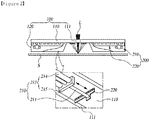
FIG. 2 is a front view illustrating an foreign object removing apparatus 1 of the present disclosure, and referring to the drawing, thescraping unit 200 of the foreign object removing apparatus 1 according to an embodiment of the present disclosure may include an expansion andcontraction driving unit 210 coupled to one surface of thehood unit 100 facing the electrical steel sheet S, and ascraper unit 220 coupled to an end portion of therod member 211 that is expanded and contracted in the expansion andcontraction driving unit 210 and in close contact with one surface of thehood unit 100 and reciprocating. - That is, if a spatter generated when a groove is formed by laser (L) irradiation on the electrical steel sheet S is attached to the
hood unit 100, in order to remove the spatter, thescraping unit 200 may include the expansion andcontraction driving unit 210 and thescraper unit 220 as a specific configuration for removing the spatter by scratching the surface of thehood unit 100 to which the spatter is attached. - The expansion and
contraction driving unit 210 serves to provide driving force for thescraper unit 220 to reciprocate on the surface of thehood unit 100. - To this end, the expansion and
contraction driving unit 210 may be provided as an actuator that reciprocates, and may include, for example, a drivingcylinder 212 of a hydraulic or pneumatic cylinder. - Here, the expansion and
contraction driving unit 210 has one end portion fixedly coupled to thehood unit 100, and the other end portion that is expanded and contracted coupled to thescraper unit 220, thereby reciprocating the scraper unit 22 - The expansion and
contraction driving unit 210 may further include arod cleaner 213 to remove spatter attached to the expansion andcontraction rod member 211, which will be described later with reference toFIG. 3 . - The
scraper unit 220 directly contacts thehood unit 100 to serve to remove foreign objects such as spatter attached to thehood unit 100. To this end, thescraper unit 220 may be coupled torod member 211 that is expanded and contracted in the expansion andcontraction driving unit 210. - The
scraper unit 220 may include acontact tab portion 222 to increase adhesion to thehood unit 100 in order to more efficiently remove the spatter, and a detailed description thereof will be described later with reference toFIG. 3 . - In order to minimize the occurrence of a problem in which the spatter is attached by exposure of the
rod member 211 to which thescraper unit 220 is coupled to the environment in which the spatter is formed, thescraper unit 220 may be coupled to be biased to therod member 211. - That is, while disposing the
rod member 211 as far away from theslit hole 111 formed in thecooling block member 110 of thehood unit 100, which is a laser (L) irradiation region where the spatter is intensively formed, so that a scraping operation by thescraper unit 220 is performed in a wider region of thecooling block member 110 of thehood unit 100, in order that therod member 211 is disposed away from theslit hole 111 and thescraper unit 220 is evenly disposed to thecooling block member 110, thescraper unit 220 is disposed to be biased to therod member 211. - In other words, the
scraper unit 220 of the foreign object removing apparatus 1 according to an embodiment of the present disclosure is biasedly coupled to an end portion of therod member 211 of the expansion andcontraction driving unit 210 that is expanded and contracted, coupled to a position biased to one side of thehood unit 100, to be evenly disposed on one surface of thehood unit 100 to reciprocate. - The expansion and
contraction driving unit 210 is provided with a pair on both sides of theslit hole 111 and provides driving force to remove a spatter, or the like, attached to the surface of thecooling block member 110 on both sides of theslit hole 111. - In addition, the
hood unit 100 of the foreign object removing apparatus 1 according to an embodiment of the present disclosure may include acooling block member 110 disposed on the electrical steel sheet S, having aslit hole 111 through which the irradiated laser L passes, having a cooling passage through which a cooling fluid flows, and to which thescraping unit 200 is coupled to one surface facing the electrical steel sheet S; and a dustcollect member 120 coupled to surround thecooling block member 110, and collecting an foreign object generated from the electrical steel sheet S. - As described above, when the
hood unit 100 forms a groove on the surface of the electrical steel sheet S for permanent magnetic domain refinement, thehood unit 100 may include acooling block member 110 preventing damage to the laser (L) device by various types of foreign objects such as a chip, a spatter, a fume, or the like, formed by laser (L) irradiation and for thermal shielding, and adust collecting member 120 provided to surround the electrical steel sheet S to which the laser L is irradiated to secure a collecting region for foreign object such as spatter, or the like. - In other words, the
cooling block member 110 is a configuration for thermal protection for the laser (L)device 3, and a cooling passage through which a cooling fluid flows may be formed, and may be disposed between one surface of the electrical steel sheet S on which laser L is irradiated and the laser (L)device 3. - The
dust collecting member 120 may be provided by being coupled to thecooling block member 110, and may be provided in a form surrounding one surface of the electrical steel sheet (S) to which the laser (L) is irradiated. -
FIG. 3 is a perspective view illustrating ascraping unit 200 of the foreign object removing apparatus 1 of the present disclosure, andFIG. 4 is a perspective view illustrating ascraper unit 220 in thescraping unit 200 of the foreign object removing apparatus 1 of the present disclosure. - Referring to the drawings, the
scraper unit 220 of the foreign object removing apparatus 1 according to an embodiment of the present disclosure may include ascraper body 221 coupled to therod member 211, and acontact tab unit 222 provided in thescraper body 221, and formed to protrude to contact one surface of thehood unit 100, the plurality of contact tab portions being formed to be spaced apart at a predetermined interval. - As described above, since the
scraper unit 220 is in direct contact with thehood unit 100 and serves to remove foreign objects such as spatter, or the like attached to thehood unit 100, thescraper unit 220 may be coupled to therod member 211 that is expanded and contracted in the expansion andcontraction driving unit 211, and in order to more efficiently remove the spatter, it may include acontact tab portion 222 to increase adhesion to thehood unit 100. - Here, the
scraper body 221 is a configuration coupled to therod member 211, and coupled to therod member 211 to be biased. That is, since the expansion andcontraction driving unit 210 is coupled adjacent to both side end portions of thecooling block member 110, which is a position to be biased around theslit hole 111 formed in thecooling block member 110 of thehood unit 100, in order for thescraper body 221 to be evenly disposed between theslit hole 111 and any one of both side end portions of thecooling block member 110, it should be coupled to therod member 211 of the expansion andcontraction driving unit 210 to be biased. - For example, when the expansion and
contraction driving unit 210 is coupled to thecooling block member 110 to be biased to the left side, thescraper body 221 is combined to therod member 211 of the expansion andcontracting driving part 210 to be biased to the right side. - The
contact tab unit 222 directly contacts thecooling block member 110 to serve to remove spatter attached to thecooling block member 110. To this end, the plurality of thecontact tab portions 222 may be provided on thescraper body 221 to protrude at regular intervals. - Unevenness portions may be formed in the
contact tab portion 222 to further increase the efficiency of removing the spatter. - That is, in the
contact tab portion 222 of the foreign object removing device 1 according to an embodiment of the present disclosure, the unevenness portions, parallel to a direction intersecting the expansion and contraction direction of therod member 211 are formed on a contact surface, in contact with one surface of thehood unit 100. - Since the
unevenness portions 222a are formed in a direction, crossing the moving direction of thecontact tab portion 222, which is a direction intersecting an expansion and contraction direction of therod member 211, it may increase an area to be scraped while increasing pressing force upon contact with one surface of thecooling block member 110. - In other words, since the
unevenness portions 222a are in line contact in a direction intersecting the moving direction of thecontact tab portion 222, although a contact area is minimized and a region to be scraped by movement forms a surface region, thereby improving spatter removal efficiency. - The expansion and
contraction driving unit 210 of the foreign object removing apparatus 1 according to an embodiment of the present disclosure may include adriving cylinder 212 fixedly coupled to one surface of thehood unit 100 and to which therod member 211 is connected in an expansion and contraction manner, and arod cleaner 213 coupled to thedriving cylinder 212, and connected to pass through the rod member to remove foreign objects attached to therod member 211. - As described above, one end portion of the expansion and
contraction driving unit 210 is fixedly coupled to the hood unit, and the other end portion that is expanded and contracted is coupled to thescraper unit 220, thereby reciprocating thescraper unit 220, and in order to remove the spatter attached to therod member 211 that is expanded and contracted, arod cleaner 213 is further included. - Here, the driving
cylinder 212 serves to provide driving force and drives therod member 211 in an expansion and contraction manner. The drivingcylinder 212 is coupled to one surface of thehood unit 100, and more specifically, is coupled to one surface of thecooling block member 110 of thehood unit 100. - The
rod cleaner 213 serves to remove the spatter attached to therod member 211. In other words, therod member 211 may be attached to the spatter as it reciprocates in a region where the spatter occurs. In this case, if the spatter attached to therod member 211 is not removed, the same problem as the above-described problem in which the spatter is attached to thehood unit 100 and falls after growth occurs. Therefore, in order to prevent this problem, therod cleaner 213 is provided with a configuration for removing spatter attached to therod member 211. - Such a
rod cleaner 213 is fixedly coupled to thedriving cylinder 212, and is configured to pass through therod member 211 that reciprocates to remove foreign objects such as a spatter, or the like, attached to therod member 211. Specifically, therod cleaner 213 includes asupport bar member 214 and asupport block member 215. - That is, the
rod cleaner 213 of the foreign object removing apparatus 1 according to an embodiment of the present disclosure may include a pair ofsupport bar members 214 having one end portion coupled to thedriving cylinder 212, and disposed adjacent to both sides of therod member 211, and asupport block member 215 coupled to the other end portion of the pair ofsupport bar members 214, and having a through-hole 215a through which therod member 211 that reciprocates, is formed. - Here, the
support block member 215 has a through-hole 215a through which therod member 211 passes, so that it substantially removes foreign objects such as spatter, or the like attached to therod member 211. - More specifically, the
support block member 215 is provided with atoothed portion 215b or abrush 215c to remove the spatter, or the like, and a detailed description thereof will be described later with reference toFIGS 5 or6 . - The
support bar member 214 is a component that serves to fix and couple thesupport block member 215 to thedriving cylinder 212, a pair of the support bar members may be disposed on both sides of therod member 211, one end portion thereof of is coupled to thedriving cylinder 212, the other end portion thereof is coupled to thesupport block member 215. - In addition, the
rod cleaner 213 may further include ascrub member 216 in order to increase the efficiency of removing the spatter, and a detailed description thereof will be described later with reference toFIG. 7 . -
FIG. 5 is a perspective view illustrating an embodiment in which asupport block member 215 includes atoothed portion 215b in thescraping unit 200 of the foreign object removing apparatus 1 of the present disclosure. Referring toFIG. 5 , in thesupport block member 215 of the foreign object removing apparatus 1 according to an embodiment of the present disclosure, atoothed portion 215b, in contact with therod member 211, is formed on an inner surface of the through-hole 215a. - That is, in order to increase an efficiency of removing foreign objects such as a spatter, or the like, attached to the
rod member 211, thesupport block member 215 is formed to have a through-hole through which therod member 211 passes, thetoothed portion 215b may be formed on the inner surface of the through-hole 215a. - A plurality of
toothed portions 215b may be formed in a form ofunevenness portions 222a to be in close contact with therod member 211 that reciprocates in the through-hole 215a, to remove foreign objects such as a spatter, or the like, horizontally with a reciprocating direction of therod member 211, and the plurality oftoothed portions 215b may also be formed in a form of theunevenness portions 222a, perpendicular to the reciprocating direction of therod member 211. -
FIG. 6 is a perspective view illustrating an embodiment in which asupport block member 215 includes abrush 215c in ascraping unit 200 of the foreign object removing apparatus 1 of the present disclosure, and referring toFIG. 6 , in thesupport block member 215 of the foreign object removing apparatus 1 according to an embodiment of the present disclosure, abrush 215c, in contact with therod member 211, is formed on an inner surface of the through-hole 215a. - That is, in order to increase efficiency of removing foreign objects attached to the
rod member 211 by forming a through-hole 215a through which thesupport block member 215 passes through therod member 211, thebrush 215c may be formed on the inner surface of the through-hole 215a. - The plurality of
brushes 215c may be formed to be perpendicular to the inner surface of the through-hole 215a so as to be in close contact with therod member 211 reciprocating to the through-hole 215a to remove foreign objects such as the spatter, or the like. - To this end, the
brush 215c may be formed of a polymer material such as a metal material, plastic, or the like, but by adjusting a diameter of hair of thebrush 215c, it may be configured to include flexibility, a degree enough to remove the attached spatter without damaging therod member 211. -
FIG. 7 is a perspective view illustrating an embodiment in which ascraping unit 200 of the foreign object removing apparatus 1 of the present disclosure includes ascrub member 216, and referring toFIG. 7 , therod cleaner 213 of the foreign object removing apparatus 1 according to an embodiment of the present disclosure may include an one end portion coupled to a portion of thesupport block member 215, adjacent to the through-hole 215a and the other end portion provided in a form of a trumpet, in contact with therod member 211. - That is, the
rod cleaner 213 may further include ascrub member 216 in order to increase efficiency of removing the spatter. - In other words, since the other end portion of the
scrub member 216 is provided as a free end, not coupled to any configuration, and is configured to be provided in contact with an outer surface of therod member 211 that reciprocates, and accordingly, the foreign object such as a spatter, or the like, attached to therod member 211 is caught on the other end portion of thescrub member 216, such that the spatter, or the like attached to therod member 211 may be eliminated from therod member 211. - Moreover, since the
scrub member 216 is formed to correspond to a diameter of therod member 211 so that only the other end portion thereof is in contact with the outer surface of therod member 211, and thescrub member 216 has a form of a trumpet of which a diameter becomes wider toward an end portion thereof, there is an advantage in that it does not affect a reciprocating movement of therod member 211, and can only scratch and remove foreign objects such as the spatter, or the like, attached to therod member 211. - While the present invention has been described with reference to exemplary embodiments in the present disclosure is not limited thereto, but various modifications may be made within the technical ideas of the present disclosure.
Claims (12)
- A foreign object removing apparatus, comprising:a hood unit provided adjacent to an electrical steel sheet, and for collecting a foreign object generated in the electrical steel sheet by laser irradiation; anda scraping unit coupled to the hood unit, and scraping and removing the foreign object attached to one surface of the hood unit facing the electrical steel sheet.
- The foreign object removing apparatus of claim 1, wherein the scraping unit comprises an expansion and contraction driving unit coupled to one surface of the hood unit facing the electrical steel sheet; and
a scraper unit coupled to an end portion of a rod member that is expanded and contracted in the expansion and contraction driving unit, and reciprocating in close contact with one surface of the hood unit. - The foreign object removing apparatus of claim 2, wherein the scraper unit is biasedly coupled to an end portion of a rod member of the expansion and contraction driving unit that is expanded and contracted, coupled to a position biased on one side of the hood unit, to be uniformly disposed on one surface of the hood unit to reciprocate.
- The foreign object removing apparatus of claim 2, wherein the scraper unit comprisesa scraper body coupled to the rod member; anda contact tab unit provided on the scraper body, and formed to protrude to contact one surface of the hood unit, the plurality of contact tab units being formed to be spaced apart at predetermined intervals.
- The foreign object removing apparatus of claim 4, wherein in the contact tab unit, unevenness portions, parallel in a direction intersecting an expansion and contraction direction of the rod member are formed on a contact surface, in contact with one surface of the hood unit.
- The foreign object removing apparatus of claim 2, wherein the expansion and contraction driving unit comprisesa driving cylinder fixedly coupled to one surface of the hood unit and to which the rod member is connected in an expansion and contraction manner; anda rod cleaner coupled to the driving cylinder, and connected to pass through the rod member to remove foreign objects attached to the rod member.
- The foreign object removing apparatus of claim 6, wherein the rod cleaner comprisesa pair of support bar members having one end portion coupled to the driving cylinder, and disposed adjacent to both sides of the rod member; anda support block member coupled to the other end portion of the pair of support bar members, and having a through-hole through which the rod member reciprocates.
- The foreign object removing apparatus of claim 7, wherein in the support block member, a toothed portion, in contact with the rod member, is formed on an inner surface of the through-hole.
- The foreign object removing apparatus of claim 7, wherein in the support block member, a brush, in contact with the rod member, is formed on an inner surface of the through-hole.
- The foreign object removing apparatus of claim 7, wherein the rod cleaner comprises a scrub member having one end portion coupled to the support block member portion, adjacent to the through-hole and the other end portion provided in a form of a trumpet, in contact with the rod member.
- The foreign object removing apparatus of claim 1, wherein the hood unit comprisesa cooling block member disposed on the electrical steel sheet, having a slit hole through which the irradiated laser passes and a cooling passage through which a cooling fluid flows, and to which the scraping unit is coupled on one surface facing the electrical steel sheet; anda dust collecting member coupled to the cooling block member to surround the cooling block member and collecting a foreign object generated from the electrical steel sheet.
- An electrical steel sheet manufacturing facility, comprising:a laser room provided on a moving path of an electrical steel sheet;a laser device provided inside the laser room, and forming a groove on a surface of the electrical steel sheet by irradiating a laser; anda foreign object removing apparatus according to any one of claims 1 to 11 provided inside the laser room, and disposed between the electrical steel sheet and the laser device.
Applications Claiming Priority (2)
| Application Number | Priority Date | Filing Date | Title |
|---|---|---|---|
| KR1020180160645A KR102075274B1 (en) | 2018-12-13 | 2018-12-13 | Alien substance removing apparatus and electrical steel sheet manufacturing facility having thereof |
| PCT/KR2019/017445 WO2020122575A1 (en) | 2018-12-13 | 2019-12-11 | Alien substance removing apparatus and electrical steel sheet manufacturing facility having thereof |
Publications (2)
| Publication Number | Publication Date |
|---|---|
| EP3895814A1 true EP3895814A1 (en) | 2021-10-20 |
| EP3895814A4 EP3895814A4 (en) | 2022-01-26 |
Family
ID=69570354
Family Applications (1)
| Application Number | Title | Priority Date | Filing Date |
|---|---|---|---|
| EP19896045.2A Pending EP3895814A4 (en) | 2018-12-13 | 2019-12-11 | Alien substance removing apparatus and electrical steel sheet manufacturing facility having thereof |
Country Status (6)
| Country | Link |
|---|---|
| US (1) | US12330191B2 (en) |
| EP (1) | EP3895814A4 (en) |
| JP (1) | JP7177939B2 (en) |
| KR (1) | KR102075274B1 (en) |
| CN (1) | CN113195118B (en) |
| WO (1) | WO2020122575A1 (en) |
Families Citing this family (3)
| Publication number | Priority date | Publication date | Assignee | Title |
|---|---|---|---|---|
| JP7278251B2 (en) * | 2020-12-02 | 2023-05-19 | プライムプラネットエナジー&ソリューションズ株式会社 | Laser processing equipment |
| JP7617426B2 (en) | 2021-07-13 | 2025-01-20 | 日本製鉄株式会社 | Laser Processing Equipment |
| KR102606745B1 (en) * | 2021-11-03 | 2023-11-29 | 주식회사 진웅테크놀러지 | Apparatus for cutting metal plate using laser beam |
Family Cites Families (17)
| Publication number | Priority date | Publication date | Assignee | Title |
|---|---|---|---|---|
| US4287405A (en) * | 1979-10-02 | 1981-09-01 | Mitsubishi Jukogyo Kabushiki Kaisha | Process and apparatus for exhausting fumes produced by arc welding |
| US4411253A (en) * | 1982-11-05 | 1983-10-25 | Devin Paul W | Ash hood |
| JPH0245504B2 (en) * | 1983-08-19 | 1990-10-09 | Gadelius Co Ltd | MIZUHEIMENJONOFUNJOBUTSUSHITSUOHAISHUTSUSURUSOCHI |
| JPS63107742U (en) * | 1986-12-27 | 1988-07-12 | ||
| GB2277699B (en) * | 1993-05-07 | 1997-05-14 | Foundry Fume Technology Limite | System for the treatment of noxious fumes and fines entrained in a gaseous stream |
| US6127648A (en) * | 1999-04-30 | 2000-10-03 | W. A. Whitney Co. | Laser-equipped machine tool having a retractable scrap removal system |
| KR200259109Y1 (en) * | 2001-09-25 | 2001-12-29 | 주식회사 덕진산업 | Rakeplate structure for waste removal machine of foul water |
| KR100829802B1 (en) * | 2001-12-17 | 2008-05-16 | 주식회사 포스코 | Automatic removal device of sediment roll surface deposit in plating bath |
| KR100948909B1 (en) | 2002-09-13 | 2010-03-24 | 주식회사 포스코 | Debris removal device for conducting roll surface in plated steel sheet manufacturing process |
| US9687884B2 (en) * | 2014-11-14 | 2017-06-27 | Slatpro Llc | Slat cleaning tool |
| CN106809712A (en) | 2015-12-02 | 2017-06-09 | 奥的斯电梯公司 | Cage guide cleaning device and its clean method |
| KR101693513B1 (en) * | 2016-01-22 | 2017-01-06 | 주식회사 포스코 | Method and apparatus for refining magnetic domains grain-oriented electrical steel |
| KR101739870B1 (en) * | 2016-01-22 | 2017-05-25 | 주식회사 포스코 | Method and apparatus for refining magnetic domains grain-oriented electrical steel |
| CN206083190U (en) * | 2016-09-13 | 2017-04-12 | 郑州华林清污起重设备有限公司 | Fixed comb harrow trash cleaning machine |
| KR101885326B1 (en) | 2016-12-22 | 2018-08-03 | 주식회사 포스코 | Method and apparatus for refining magnetic domains grain-oriented electrical steel |
| CN207025915U (en) * | 2017-07-14 | 2018-02-23 | 衢州索迈气动元件有限公司 | A kind of dust arrester for cylinder piston rod |
| CN108032081B (en) * | 2018-02-06 | 2024-09-13 | 江苏大金激光科技有限公司 | Laser cutting machine with steel plate surface treatment device |
-
2018
- 2018-12-13 KR KR1020180160645A patent/KR102075274B1/en active Active
-
2019
- 2019-12-11 US US17/312,668 patent/US12330191B2/en active Active
- 2019-12-11 WO PCT/KR2019/017445 patent/WO2020122575A1/en not_active Ceased
- 2019-12-11 CN CN201980082716.1A patent/CN113195118B/en active Active
- 2019-12-11 JP JP2021533291A patent/JP7177939B2/en active Active
- 2019-12-11 EP EP19896045.2A patent/EP3895814A4/en active Pending
Also Published As
| Publication number | Publication date |
|---|---|
| JP7177939B2 (en) | 2022-11-24 |
| KR102075274B1 (en) | 2020-02-07 |
| CN113195118A (en) | 2021-07-30 |
| CN113195118B (en) | 2023-05-16 |
| US12330191B2 (en) | 2025-06-17 |
| EP3895814A4 (en) | 2022-01-26 |
| WO2020122575A1 (en) | 2020-06-18 |
| US20220048136A1 (en) | 2022-02-17 |
| JP2022512362A (en) | 2022-02-03 |
Similar Documents
| Publication | Publication Date | Title |
|---|---|---|
| US12330191B2 (en) | Alien substance removing apparatus and electrical steel sheet manufacturing facility having thereof | |
| KR101155069B1 (en) | Substrates and methods of using those substrates | |
| US4318786A (en) | Electrolytic decontamination | |
| CN110504099A (en) | A kind of method and system of laser ablation inductance copper coil paint layer | |
| KR101739870B1 (en) | Method and apparatus for refining magnetic domains grain-oriented electrical steel | |
| CN105234636B (en) | Stainless steel ring forging welding procedure | |
| CN110744195A (en) | Welding process of high-power laser welding equipment for thin plates | |
| EP3858461B1 (en) | Foreign substance collecting apparatus and electrical steel sheet manufacturing facility including same | |
| KR100520539B1 (en) | A removing device for laser welding spatter | |
| US20210268587A1 (en) | Splatter shield systems and methods for additive manufacturing | |
| KR20210113335A (en) | Glass manufacturing apparatus and method | |
| CN118023794A (en) | Welding mechanical arm of cast-welded structural part preheating-free welding robot | |
| CN112276357B (en) | Optical fiber laser welding device | |
| WO2012010740A1 (en) | Method for removing an oxidation from the surface of a metal object | |
| CN114728375B (en) | Foreign matter trapping device and electrical steel sheet manufacturing equipment comprising same | |
| DE3041095C2 (en) | Arc device for surface treatment of long workpieces | |
| CN213194881U (en) | Thermal battery sealing cover component oxide skin laser cleaning equipment | |
| CN216397400U (en) | Annular facula laser cleaning system | |
| CN121372975A (en) | Laser cleaning equipment | |
| JP2004130337A (en) | Laser equipment and laser processing machine | |
| JP3042560U (en) | Self-propelled paint stripping device | |
| CN119680961A (en) | Laser cleaning equipment | |
| JPS605395B2 (en) | Laser processing equipment | |
| KR20250131587A (en) | Brush processing apparatus and brush processing method using the same | |
| KR20240059505A (en) | Device for manufacturing electrode |
Legal Events
| Date | Code | Title | Description |
|---|---|---|---|
| STAA | Information on the status of an ep patent application or granted ep patent |
Free format text: STATUS: THE INTERNATIONAL PUBLICATION HAS BEEN MADE |
|
| PUAI | Public reference made under article 153(3) epc to a published international application that has entered the european phase |
Free format text: ORIGINAL CODE: 0009012 |
|
| STAA | Information on the status of an ep patent application or granted ep patent |
Free format text: STATUS: REQUEST FOR EXAMINATION WAS MADE |
|
| 17P | Request for examination filed |
Effective date: 20210702 |
|
| AK | Designated contracting states |
Kind code of ref document: A1 Designated state(s): AL AT BE BG CH CY CZ DE DK EE ES FI FR GB GR HR HU IE IS IT LI LT LU LV MC MK MT NL NO PL PT RO RS SE SI SK SM TR |
|
| A4 | Supplementary search report drawn up and despatched |
Effective date: 20220105 |
|
| RIC1 | Information provided on ipc code assigned before grant |
Ipc: B23Q 11/00 20060101ALI20211222BHEP Ipc: B23K 26/16 20060101ALI20211222BHEP Ipc: C21D 10/00 20060101ALI20211222BHEP Ipc: B08B 15/02 20060101ALI20211222BHEP Ipc: B08B 1/00 20060101AFI20211222BHEP |
|
| DAV | Request for validation of the european patent (deleted) | ||
| DAX | Request for extension of the european patent (deleted) | ||
| RAP3 | Party data changed (applicant data changed or rights of an application transferred) |
Owner name: POSCO HOLDINGS INC. |
|
| RAP1 | Party data changed (applicant data changed or rights of an application transferred) |
Owner name: POSCO CO., LTD |
|
| STAA | Information on the status of an ep patent application or granted ep patent |
Free format text: STATUS: EXAMINATION IS IN PROGRESS |
|
| 17Q | First examination report despatched |
Effective date: 20230217 |