EP3895776A1 - Adapter for filter device and method of use - Google Patents
Adapter for filter device and method of use Download PDFInfo
- Publication number
- EP3895776A1 EP3895776A1 EP21163505.7A EP21163505A EP3895776A1 EP 3895776 A1 EP3895776 A1 EP 3895776A1 EP 21163505 A EP21163505 A EP 21163505A EP 3895776 A1 EP3895776 A1 EP 3895776A1
- Authority
- EP
- European Patent Office
- Prior art keywords
- wall
- filter
- fluid flow
- hollow
- filter device
- Prior art date
- Legal status (The legal status is an assumption and is not a legal conclusion. Google has not performed a legal analysis and makes no representation as to the accuracy of the status listed.)
- Granted
Links
Images





Classifications
-
- B—PERFORMING OPERATIONS; TRANSPORTING
- B01—PHYSICAL OR CHEMICAL PROCESSES OR APPARATUS IN GENERAL
- B01D—SEPARATION
- B01D29/00—Filters with filtering elements stationary during filtration, e.g. pressure or suction filters, not covered by groups B01D24/00 - B01D27/00; Filtering elements therefor
- B01D29/11—Filters with filtering elements stationary during filtration, e.g. pressure or suction filters, not covered by groups B01D24/00 - B01D27/00; Filtering elements therefor with bag, cage, hose, tube, sleeve or like filtering elements
- B01D29/13—Supported filter elements
- B01D29/15—Supported filter elements arranged for inward flow filtration
- B01D29/21—Supported filter elements arranged for inward flow filtration with corrugated, folded or wound sheets
-
- B—PERFORMING OPERATIONS; TRANSPORTING
- B01—PHYSICAL OR CHEMICAL PROCESSES OR APPARATUS IN GENERAL
- B01D—SEPARATION
- B01D35/00—Filtering devices having features not specifically covered by groups B01D24/00 - B01D33/00, or for applications not specifically covered by groups B01D24/00 - B01D33/00; Auxiliary devices for filtration; Filter housing constructions
- B01D35/30—Filter housing constructions
- B01D35/306—Filter mounting adapter
-
- B—PERFORMING OPERATIONS; TRANSPORTING
- B01—PHYSICAL OR CHEMICAL PROCESSES OR APPARATUS IN GENERAL
- B01D—SEPARATION
- B01D29/00—Filters with filtering elements stationary during filtration, e.g. pressure or suction filters, not covered by groups B01D24/00 - B01D27/00; Filtering elements therefor
- B01D29/11—Filters with filtering elements stationary during filtration, e.g. pressure or suction filters, not covered by groups B01D24/00 - B01D27/00; Filtering elements therefor with bag, cage, hose, tube, sleeve or like filtering elements
- B01D29/31—Self-supporting filtering elements
- B01D29/33—Self-supporting filtering elements arranged for inward flow filtration
-
- B—PERFORMING OPERATIONS; TRANSPORTING
- B01—PHYSICAL OR CHEMICAL PROCESSES OR APPARATUS IN GENERAL
- B01D—SEPARATION
- B01D29/00—Filters with filtering elements stationary during filtration, e.g. pressure or suction filters, not covered by groups B01D24/00 - B01D27/00; Filtering elements therefor
- B01D29/11—Filters with filtering elements stationary during filtration, e.g. pressure or suction filters, not covered by groups B01D24/00 - B01D27/00; Filtering elements therefor with bag, cage, hose, tube, sleeve or like filtering elements
- B01D29/13—Supported filter elements
-
- B—PERFORMING OPERATIONS; TRANSPORTING
- B01—PHYSICAL OR CHEMICAL PROCESSES OR APPARATUS IN GENERAL
- B01D—SEPARATION
- B01D29/00—Filters with filtering elements stationary during filtration, e.g. pressure or suction filters, not covered by groups B01D24/00 - B01D27/00; Filtering elements therefor
- B01D29/62—Regenerating the filter material in the filter
- B01D29/66—Regenerating the filter material in the filter by flushing, e.g. counter-current air-bumps
-
- B—PERFORMING OPERATIONS; TRANSPORTING
- B01—PHYSICAL OR CHEMICAL PROCESSES OR APPARATUS IN GENERAL
- B01D—SEPARATION
- B01D2201/00—Details relating to filtering apparatus
- B01D2201/04—Supports for the filtering elements
- B01D2201/0407—Perforated supports on both sides of the filtering element
-
- B—PERFORMING OPERATIONS; TRANSPORTING
- B01—PHYSICAL OR CHEMICAL PROCESSES OR APPARATUS IN GENERAL
- B01D—SEPARATION
- B01D2201/00—Details relating to filtering apparatus
- B01D2201/08—Regeneration of the filter
- B01D2201/085—Regeneration of the filter using another chemical than the liquid to be filtered
-
- B—PERFORMING OPERATIONS; TRANSPORTING
- B01—PHYSICAL OR CHEMICAL PROCESSES OR APPARATUS IN GENERAL
- B01D—SEPARATION
- B01D2201/00—Details relating to filtering apparatus
- B01D2201/29—Filter cartridge constructions
- B01D2201/291—End caps
-
- B—PERFORMING OPERATIONS; TRANSPORTING
- B01—PHYSICAL OR CHEMICAL PROCESSES OR APPARATUS IN GENERAL
- B01D—SEPARATION
- B01D2201/00—Details relating to filtering apparatus
- B01D2201/30—Filter housing constructions
- B01D2201/301—Details of removable closures, lids, caps, filter heads
- B01D2201/302—Details of removable closures, lids, caps, filter heads having inlet or outlet ports
-
- B—PERFORMING OPERATIONS; TRANSPORTING
- B01—PHYSICAL OR CHEMICAL PROCESSES OR APPARATUS IN GENERAL
- B01D—SEPARATION
- B01D2201/00—Details relating to filtering apparatus
- B01D2201/30—Filter housing constructions
- B01D2201/301—Details of removable closures, lids, caps, filter heads
- B01D2201/306—Closures, lids, caps or filter heads forming one element with the filtering element
Definitions
- Some filter devices require the use of an adapter when installing a filter into a filter housing when the filter comprises a polymer that is different than the filter housing polymer. However, there is a need for improved filter devices.
- the present invention provides for ameliorating at least some of the disadvantages of the prior art.
- An embodiment of the invention provides a filter device comprising: (a) a filter comprising a hollow cylindrical filter element comprising a porous medium, arranged in a filter housing comprising an outer cage, an inner core, a first end cap, and a second end cap, wherein the outer cage and inner core are sealed to the first end cap and the second end cap with the filter element between the outer cage and the inner core, the second end cap comprising a closed end cap and the first end cap comprising an open end cap including a hollow projection comprising a filter outlet, the hollow projection having an external wall; (b) a filter device housing comprising a head including an inlet port and an outlet port, and a bowl having an interior for receiving the filter; (c) an adapter comprising a hollow body having: (i) a top portion having a top portion tapered inner diameter, wherein the top portion tapered inner diameter has a maximum diameter and a minimum diameter; (ii) a bottom portion; and (iii) a central fluid flow port passing through the hollow body, the
- an adapter for use in a filter device comprises: a hollow body having: (i) a top portion having a top portion tapered inner diameter, wherein the top portion tapered inner diameter has a maximum diameter and a minimum diameter; (ii) a bottom portion; and (iii) a central fluid flow port passing through the hollow body, the central fluid flow port having a first end and a second end, an inside wall and an outside wall, the central fluid flow port being in fluid communication with the filter outlet; the top portion including a downwardly slanted inner wall providing the top portion tapered inner diameter, the downwardly slanted inner wall being connected to the first end of the central fluid flow port at the minimum diameter of the top portion tapered inner diameter, the downwardly slanted inner wall having an upper surface and two or more hollow passageways passing through the upper surface of the downwardly slanted inner wall, each of the two or more hollow passageways including an upper passageway end and a lower passageway end, the upper surface of the downwardly slanted inner
- a filter device comprising: (a) a filter comprising a hollow cylindrical filter element comprising a porous medium, arranged in a filter housing comprising an outer cage, an inner core, a first end cap, and a second end cap, wherein the outer cage and inner core are sealed to the first end cap and the second end cap with the filter element between the outer cage and the inner core, the second end cap comprising a closed end cap and the first end cap comprising an open end cap including a hollow projection comprising a filter outlet, the hollow projection having an external wall; (b) a filter device housing comprising a head including an inlet port and an outlet port, and a bowl having an interior for receiving the filter; (c) an adapter comprising a hollow body having: (i) a top portion having a top portion tapered inner diameter, wherein the top portion tapered inner diameter has a maximum diameter and a minimum diameter; (ii) a bottom portion; and (iii) a central fluid flow port passing through
- the adapter and the filter device housing (especially the filter device housing head) each comprise a fluoropolymer, more preferably, a perfluoroalkoxy alkane (PFA).
- PFA perfluoroalkoxy alkane
- the filter (especially the first end cap) comprises polypropylene or polyethylene.
- an adapter for use in a filter device comprises: a hollow body having: (i) a top portion having a top portion tapered inner diameter, wherein the top portion tapered inner diameter has a maximum diameter and a minimum diameter; (ii) a bottom portion; and (iii) a central fluid flow port passing through the hollow body, the central fluid flow port having a first end and a second end, an inside wall and an outside wall, the central fluid flow port being in fluid communication with the filter outlet; the top portion including a downwardly slanted inner wall providing the top portion tapered inner diameter, the downwardly slanted inner wall being connected to the first end of the central fluid flow port at the minimum diameter of the top portion tapered inner diameter, the downwardly slanted inner wall having an upper surface and two or more hollow passageways passing through the upper surface of the downwardly slanted inner wall, each of the two or more hollow passageways including an upper passageway end and a lower passageway end, the upper surface of the downwardly slanted inner
- dead space in the filter device is reduced.
- dead space can be reduced during assembly of the filter device, and dead space can be reduced while preparing the filter device for shipping (e.g., including cleaning with a cleaning fluid such as an acid, and replacing the cleaning fluid with deionized water) advantageously allowing quick and efficient liquid displacement.
- process start up time of the installed filter device at the user's site can be reduced.
- the adapter provides a heat shield to prevent melting filter components during welding, and also provides efficient sealing.
- a method of assembling a filter device comprises placing an embodiment of an adapter including hollow passageways according to the invention on top of a filter comprising a hollow cylindrical filter element comprising a porous medium, arranged in a filter housing comprising a first end cap, and a second end cap, the second end cap comprising a closed end cap and the first end cap comprising an open end cap including a hollow projection comprising a filter outlet, the hollow projection having an external wall, wherein the filter is arranged in a bowl of a filter device housing; pushing the adapter downwardly and passing some air present in the filter and/or bowl of the filter device housing through the hollow passageways; and, welding a head of the filter device housing and passing the air passing through the hollow passageways through an outlet port in the head of the filter device housing.
- a method of cleaning a filter comprising passing a cleaning fluid through an embodiment of the filter device, and passing deionized water through the filter device to flush the cleaning fluid from the filter device.
- a method of filtering a fluid comprising passing fluid along a fluid flow path through an embodiment of the filter device. For example, fluid is passed through the inlet port, the filter, and the filtered fluid passes through the filter outlet, the adapter central fluid flow port, and the outlet port.
- the method includes venting air or gas through the vent port, before filtration, and, if appropriate, during filtration.
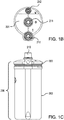
- Figure 1A is cross-sectional view of an embodiment of a filter device 500 including an adapter 100 according to an embodiment of the invention, wherein the adapter is welded to the filter device housing 200, and the adapter is sealed to an end of the filter 50.
- Figure 1B is a top view of the head 201 of the filter device, and
- Figure 1C is a left side view of the filter device showing the filter device housing.
- the filter device 500 comprises a filter device housing 200 comprising a head 201 including an inlet port 210 and an outlet port 211, and a bowl 202 having an interior 300 for receiving a filter 50 (shown in more detail in Figure 3 ), the filter comprising a hollow cylindrical filter element 10 comprising a porous medium 11, arranged in a filter housing 51 comprising an outer cage 52, an inner core 53, a first end cap 54A, and a second end cap 54B, wherein the outer cage and inner core are sealed to the first end cap and the second end cap with the filter element between the outer cage and the inner core, the second end cap comprising a closed end cap and the first end cap comprising an open end cap including a hollow projection 55 comprising a filter outlet 56, the hollow projection having a top wall 57, an inner wall 58, and an external wall 59 including grooves 59A, 59B, for receiving resilient members 60A, 60B, shown as o-rings.
- the filter comprising a hollow cylindrical filter element 10 comprising a por
- an adapter 100 (shown in more detail in Figures 2A-2F ) comprises a hollow body 101 having a top portion 110 having a top portion tapered inner diameter 111, wherein the top portion tapered inner diameter has a maximum diameter 111A and a minimum diameter 111B; a bottom portion 150; and a central fluid flow port 130 passing through the hollow body 101, the central fluid flow port having a first end 131 and a second end 132, an inside wall 133A and an outside wall 133B, the central fluid flow port 130 being in fluid communication with the filter outlet 56; the top portion 110 including a downwardly inwardly slanted inner wall 120 providing the top portion tapered inner diameter 111, the downwardly slanted inner wall 120 being connected to the first end 131 of the central fluid flow port at the minimum diameter 111B of the top portion tapered inner diameter, the downwardly slanted inner wall having an upper surface 121 and two or more hollow passageways 125 (6 passageways are illustrated) passing through the upper surface 121
- the hollow passageways 125 shown in Figure 2F are arranged slanted inwardly from the second ends 125B toward the first ends 125A.
- the taper angle is about 30 degrees, and the angle of slant with respect to the horizontal axis ("H-H" in Figure 7A ) is about 75 degrees.
- Figure 4A is cross-sectional view of another embodiment of a filter device 500' including an adapter 100' according to another embodiment of the invention, wherein the adapter is welded to the filter device housing 200', and the adapter is sealed to an end of the filter 50'.
- Figure 4B is a top view of the head 201' of the filter device, and
- Figure 4C is a left side view of the filter device showing the filter device housing.
- the filter device 500' comprises a filter device housing 200' comprising a head 201' including an inlet port 210' and an outlet port 211', and a bowl 202' having an interior 300' for receiving a filter 50' (shown in more detail in Figure 6 ), the filter comprising a hollow cylindrical filter element 10' comprising a porous medium 11', arranged in a filter housing 51' comprising an outer cage 52', an inner core 53', a first end cap 54A', and a second end cap 54B', wherein the outer cage and inner core are sealed to the first end cap and the second end cap with the filter element between the outer cage and the inner core, the second end cap comprising a closed end cap and the first end cap comprising an open end cap including a hollow projection 55' comprising a filter outlet 56', the hollow projection having a top wall 57', an inner wall 58', and an external wall 59' including grooves 59A', 59B', for
- an adapter 100' (shown in more detail in Figures 5A-5F ) comprises a hollow body 101' having a top portion 110' having a top portion tapered inner diameter 111', wherein the top portion tapered inner diameter has a maximum diameter 111A' and a minimum diameter 111B'; a bottom portion 150'; and a central fluid flow port 130' passing through the hollow body 101', the central fluid flow port having a first end 131' and a second end 132', an inside wall 133A' and an outside wall 133B', the central fluid flow port 130' being in fluid communication with the filter outlet 56'; the top portion 110' including a downwardly inwardly slanted inner wall 120' providing the top portion tapered inner diameter 111', the downwardly slanted inner wall 120' being connected to the first end 131' of the central fluid flow port at the minimum diameter 111B' of the top portion tapered inner diameter, the downwardly slanted inner wall having an upper surface 121'
- Embodiments of the invention can include any number of hollow passageways in the adapter 100, 100'.
- embodiments of the adapter, filter and/or filter device can include additional components such as one of more external tabs protruding from the external wall of the adapter (e.g., the embodiment shown in Figures 2A-2F shows 3 tabs 190 to maintain spacing between the adapter and the inside of the bowl, as well as a plurality of feet (3 feet 191 are illustrated in the embodiment shown in Figures 2A-2F ) to provide spacing between the bottom portion 150 of the adapter 100 and the top surface of the first end cap 54A.
- additional components such as one of more external tabs protruding from the external wall of the adapter (e.g., the embodiment shown in Figures 2A-2F shows 3 tabs 190 to maintain spacing between the adapter and the inside of the bowl, as well as a plurality of feet (3 feet 191 are illustrated in the embodiment shown in Figures 2A-2F ) to provide spacing between the bottom portion 150 of the adapter 100 and the top surface of the first end cap 54A.
- other optional components include a downwardly projecting collar on the bottom portion of the adapter (e.g., illustrated as 180 in the embodiment of the adapter shown in Figures 2A-2F ) providing a spacer, and/or an upwardly projecting collar on the upper portion of the adapter (e.g., shown as 195 in embodiment shown in Figures 2A-2F and shown as 195' in the embodiment shown in Figures 5A-5D ; in some embodiments, 195/195' provide the same cubic volume as the projecting collar on the opposite side of the head ( see, for example, Fig. 4A ) to provide the same depth of melting area during welding).
- the first end cap 54A' includes an optional collar 70' providing a shoulder for seating the bottom portion of the adapter 100'.
- the outer appearance of the top portion 110, 110' (e.g., below collar 195, 195') has a general dome shape, thus reducing material needed while providing for efficient heat shielding and welding.
- the adapter 100, 100' is assembled in the filter device housing 200, 200' dead space is reduced as air present in the filter device housing is passed through the hollow passageways 125, 125' ( see also, Figure 7A ) and through the outlet port 211, 211' after feet 191 (if present) contact the first end cap 54A with some clearance between the top wall 57, 57' of the outlet 56, 56' and the base 161, 161' of the annular channel 162, 162', and the adapter is welded (e.g., via platen welding) to the filter device housing head 201, 201', preferably wherein the head 201, 201' is welded to the bowl 202 at the same time, and, due to the presence of the resilient members 60A, 60B, 60A', 60B', the outer side wall 162, 162' is sealed against the hollow projection 55, 55' comprising the filter outlet 56, 56'.
- the adapter 100, 100' provides a heat shield to prevent thermal damage to the filter outlet 56
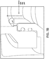
- dead space is further reduced during filtration; without being bound to any particular theory, it is believed that dead space is reduced as the downwardly slanted inner wall ( see, Figure 7A ) minimizes whirls of flow and stagnation areas that could occur in the absence of the downwardly slanted inner wall ( see, Figure 7B showing possible whirls of flow and stagnation areas).
- the oblique angle of the inwardly and downwardly slanted inner wall, with respect to a center line of the shape of the hollow passageways 125, 125' is in the range of from about 30 degrees to about 60 degrees.
- fluid communication between the central fluid flow port 130 and the hollow passageways 125 by the about 30 degree to about 60 degree angle also reduces dead space.
- a fluid flow path 600, 600' passes though the filter device 500, 500' via the inlet port 210, 210', the optional outer cage 52, 52' (if present), the porous medium 11, 11', the optional inner core 53, 53' (if present), the filter outlet 56, 56', the adapter central fluid flow port 130, 130', and the outlet port 211, 211'.
- the filter device can be vented through vent port 212, 212'.
- a conduit can be connected to the vent port, and a flow control device such as a valve can be associated with the conduit to allow or stop flow through the vent port and conduit.
- the filter is used for filtering fluid for the microelectronics industry (for example, in the preparation of wafers), e.g., fluids including one or more of any of the following: ammonium hydroxide, hydrochloric acid, hydrogen peroxide, and deionized water.
- fluids including one or more of any of the following: ammonium hydroxide, hydrochloric acid, hydrogen peroxide, and deionized water.
- the filter can be used with chemical cleaning chemistries such as ammonium hydroxide hydrogen peroxide mixture (SC-1), and hydrochloric acid peroxide mixture (SC-2).
- the filter can include additional elements, layers, or components, that can have different structures and/or functions, e.g., at least one of any one or more of the following: prefiltration, support, drainage, spacing and cushioning.
- the filter can also include at least one additional element such as a mesh and/or a screen.
- the filter device is sterilizable. Any housing of suitable shape and providing at least one inlet and at least one outlet may be employed.
- the filter device housing and filter housing can be fabricated from any suitable impervious polymeric material which is compatible with the fluid being processed.
- the filter device housing is fabricated from a fluoropolymer, preferably a perfluoroalkoxy alkane (PFA), and at least the end caps of the filter housing are fabricated from polypropylene or polyethylene.
- PFA perfluoroalkoxy alkane
- This example shows the improvement in liquid displacement in filter devices including an adapter with hollow passageways according to an embodiment of the invention, compared to filter devices including an adapter without hollow passageways.
- the adapters are attached on the filters and installed into the bowl, followed by platen welded with the heads and bowls.
- the filter devices are installed in parallel, and cleaned with 3.5% hydrochloric acid, followed by flushing with deionized water.
- the flow rate is about 24 liters/min, and the resistivity of the filtered fluid is monitored. The process is stopped when the resistivity is over 15 mega ohm centimeters.
- the 5 filter devices with adapters without hollow passageways provide fluid with a resistivity of over 15 mega ohm centimeters within 4 hours.
- the 5 filter devices with adapters according to an embodiment of the invention provide fluid with a resistivity of over 17.5 mega ohm centimeters within 1 hour, thus showing improved liquid displacement.
Landscapes
- Chemical & Material Sciences (AREA)
- Chemical Kinetics & Catalysis (AREA)
- Separation Using Semi-Permeable Membranes (AREA)
- Filtering Of Dispersed Particles In Gases (AREA)
- Filtration Of Liquid (AREA)
Abstract
Description
- Some filter devices require the use of an adapter when installing a filter into a filter housing when the filter comprises a polymer that is different than the filter housing polymer. However, there is a need for improved filter devices.
- The present invention provides for ameliorating at least some of the disadvantages of the prior art. These and other advantages of the present invention will be apparent from the description as set forth below.
- An embodiment of the invention provides a filter device comprising: (a) a filter comprising a hollow cylindrical filter element comprising a porous medium, arranged in a filter housing comprising an outer cage, an inner core, a first end cap, and a second end cap, wherein the outer cage and inner core are sealed to the first end cap and the second end cap with the filter element between the outer cage and the inner core, the second end cap comprising a closed end cap and the first end cap comprising an open end cap including a hollow projection comprising a filter outlet, the hollow projection having an external wall; (b) a filter device housing comprising a head including an inlet port and an outlet port, and a bowl having an interior for receiving the filter; (c) an adapter comprising a hollow body having: (i) a top portion having a top portion tapered inner diameter, wherein the top portion tapered inner diameter has a maximum diameter and a minimum diameter; (ii) a bottom portion; and (iii) a central fluid flow port passing through the hollow body, the central fluid flow port having a first end and a second end, an inside wall and an outside wall, the central fluid flow port being in fluid communication with the filter outlet; the top portion including a downwardly slanted inner wall providing the top portion tapered inner diameter, the downwardly slanted inner wall being connected to the first end of the central fluid flow port at the minimum diameter of the top portion tapered inner diameter, the downwardly slanted inner wall having an upper surface and two or more hollow passageways passing through the upper surface of the downwardly slanted inner wall, each of the two or more hollow passageways including an upper passageway end and a lower passageway end, the upper surface of the downwardly slanted inner wall including the upper passageway ends; the bottom portion including a downwardly extending hollow tubular element including the second end of the central fluid flow port, the hollow tubular element providing the inside wall and outside wall of the central fluid flow port; the bottom portion including an annular channel surrounding the downwardly extending hollow tubular element, the annular channel comprising a base, an outer side wall, and an inner side wall comprising the outside wall of the central fluid flow port, the base of the annular channel including the lower passageway ends of the two or more hollow passageways; wherein the outer side wall of the annular channel seals against the external wall of the hollow projection comprising the filter outlet, and the adapter is welded to the filter device housing head and to the top portion of the adapter; and wherein a fluid flow path passes though the inlet port, the outer cage, the porous medium, the filter outlet, the adapter central fluid flow port, and the outlet port.
- In accordance with another embodiment, an adapter for use in a filter device comprises: a hollow body having: (i) a top portion having a top portion tapered inner diameter, wherein the top portion tapered inner diameter has a maximum diameter and a minimum diameter; (ii) a bottom portion; and (iii) a central fluid flow port passing through the hollow body, the central fluid flow port having a first end and a second end, an inside wall and an outside wall, the central fluid flow port being in fluid communication with the filter outlet; the top portion including a downwardly slanted inner wall providing the top portion tapered inner diameter, the downwardly slanted inner wall being connected to the first end of the central fluid flow port at the minimum diameter of the top portion tapered inner diameter, the downwardly slanted inner wall having an upper surface and two or more hollow passageways passing through the upper surface of the downwardly slanted inner wall, each of the two or more hollow passageways including an upper passageway end and a lower passageway end, the upper surface of the downwardly slanted inner wall including the upper passageway ends; the bottom portion including a downwardly extending hollow tubular element including the second end of the central fluid flow port, the hollow tubular element providing the inside wall and outside wall of the central fluid flow port; the bottom portion including an annular channel surrounding the downwardly extending hollow tubular element, the annular channel comprising a base, an outer side wall, and an inner side wall comprising the outside wall of the central fluid flow port, the base of the annular channel including the lower passageway ends of the two or more hollow passageways.
-
-
Figure 1A is cross-sectional view of an embodiment of a filter device including a filter device housing, a filter, and an adapter including a downwardly slanted inner wall and a slanted hollow passageway according to an embodiment of the invention, wherein the adapter is welded to the filter device housing, and the adapter is sealed to an end of the filter;Figure 1B is a top view of the filter device shown inFigure 1A , andFigure 1C is a left side view of the filter device shown inFigure 1A . -
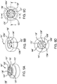
Figure 2A is a top perspective view of the embodiment of the adapter shown in the filter device shown inFigure 1A ;Figure 2B is a bottom perspective view,Figure 2C is a top view;Figure 2D is a bottom view,Figure 2E is a sectional view along line A-A ofFigure 2C , andFigure 2F is a sectional view along line B-B ofFigure 2C . -
Figure 3 is a cross-sectional view of the filter in the filter device shown inFigure 1A . -
Figure 4A is cross-sectional view of an embodiment of a filter device including a filter device housing, a filter, and an adapter including a downwardly slanted inner wall and a hollow passageway according to an embodiment of the invention, wherein the adapter is welded to the filter device housing, and the adapter is sealed to an end of the filter;Figure 4B is a top view of the filter device shown inFigure 4A , andFigure 4C is a left side view of the filter device shown inFigure 4A . -
Figure 5A is a top perspective view of the embodiment of the adapter shown in the filter device shown inFigure 4A ;Figure 5B is a bottom perspective view,Figure 5C is a top view;Figure 5D is a bottom view,Figure 5E is a sectional view along line C-C ofFigure 5C , andFigure 5F is a sectional view along line D-D ofFigure 5C . -
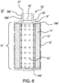
Figure 6 is a cross-sectional view of the filter in the filter device shown inFigure 4A . -
Figure 7A is a partial diagrammatic view of the filter device shown inFigure 1 , showing flow along fluid flow paths along the central fluid flow path (black arrows), and through a hollow passageway (white arrows), in the adapter.Figure 7B is a partial diagrammatic view of illustrative flow along a central fluid flow path of an adapter lacking a downwardly slanted inner wall and hollow passageways. - In accordance with an embodiment of the invention, a filter device is provided comprising: (a) a filter comprising a hollow cylindrical filter element comprising a porous medium, arranged in a filter housing comprising an outer cage, an inner core, a first end cap, and a second end cap, wherein the outer cage and inner core are sealed to the first end cap and the second end cap with the filter element between the outer cage and the inner core, the second end cap comprising a closed end cap and the first end cap comprising an open end cap including a hollow projection comprising a filter outlet, the hollow projection having an external wall; (b) a filter device housing comprising a head including an inlet port and an outlet port, and a bowl having an interior for receiving the filter; (c) an adapter comprising a hollow body having: (i) a top portion having a top portion tapered inner diameter, wherein the top portion tapered inner diameter has a maximum diameter and a minimum diameter; (ii) a bottom portion; and (iii) a central fluid flow port passing through the hollow body, the central fluid flow port having a first end and a second end, an inside wall and an outside wall, the central fluid flow port being in fluid communication with the filter outlet; the top portion including a downwardly slanted inner wall providing the top portion tapered inner diameter, the downwardly slanted inner wall being connected to the first end of the central fluid flow port at the minimum diameter of the top portion tapered inner diameter, the downwardly slanted inner wall having an upper surface and two or more hollow passageways passing through the upper surface of the downwardly slanted inner wall, each of the two or more hollow passageways including an upper passageway end and a lower passageway end, the upper surface of the downwardly slanted inner wall including the upper passageway ends; the bottom portion including a downwardly extending hollow tubular element including the second end of the central fluid flow port, the hollow tubular element providing the inside wall and outside wall of the central fluid flow port; the bottom portion including an annular channel surrounding the downwardly extending hollow tubular element, the annular channel comprising a base, an outer side wall, and an inner side wall comprising the outside wall of the central fluid flow port, the base of the annular channel including the lower passageway ends of the two or more hollow passageways; wherein the outer side wall of the annular channel seals against the external wall of the hollow projection comprising the filter outlet, and the adapter is welded to the filter device housing head and to the top portion of the adapter; and wherein a fluid flow path passes though the inlet port, the outer cage, the porous medium, the filter outlet, the adapter central fluid flow port, and the outlet port.
- In a preferred embodiment, the adapter and the filter device housing (especially the filter device housing head) each comprise a fluoropolymer, more preferably, a perfluoroalkoxy alkane (PFA).
- In an embodiment, the filter (especially the first end cap) comprises polypropylene or polyethylene.
- In accordance with another embodiment, an adapter for use in a filter device comprises: a hollow body having: (i) a top portion having a top portion tapered inner diameter, wherein the top portion tapered inner diameter has a maximum diameter and a minimum diameter; (ii) a bottom portion; and (iii) a central fluid flow port passing through the hollow body, the central fluid flow port having a first end and a second end, an inside wall and an outside wall, the central fluid flow port being in fluid communication with the filter outlet; the top portion including a downwardly slanted inner wall providing the top portion tapered inner diameter, the downwardly slanted inner wall being connected to the first end of the central fluid flow port at the minimum diameter of the top portion tapered inner diameter, the downwardly slanted inner wall having an upper surface and two or more hollow passageways passing through the upper surface of the downwardly slanted inner wall, each of the two or more hollow passageways including an upper passageway end and a lower passageway end, the upper surface of the downwardly slanted inner wall including the upper passageway ends; the bottom portion including a downwardly extending hollow tubular element including the second end of the central fluid flow port, the hollow tubular element providing the inside wall and outside wall of the central fluid flow port; the bottom portion including an annular channel surrounding the downwardly extending hollow tubular element, the annular channel comprising a base, an outer side wall, and an inner side wall comprising the outside wall of the central fluid flow port, the base of the annular channel including the lower passageway ends of the two or more hollow passageways.
- Advantageously, dead space in the filter device is reduced. For example, dead space can be reduced during assembly of the filter device, and dead space can be reduced while preparing the filter device for shipping (e.g., including cleaning with a cleaning fluid such as an acid, and replacing the cleaning fluid with deionized water) advantageously allowing quick and efficient liquid displacement. Moreover, process start up time of the installed filter device at the user's site can be reduced.
- In another advantage, the adapter provides a heat shield to prevent melting filter components during welding, and also provides efficient sealing.
- In an embodiment, a method of assembling a filter device comprises placing an embodiment of an adapter including hollow passageways according to the invention on top of a filter comprising a hollow cylindrical filter element comprising a porous medium, arranged in a filter housing comprising a first end cap, and a second end cap, the second end cap comprising a closed end cap and the first end cap comprising an open end cap including a hollow projection comprising a filter outlet, the hollow projection having an external wall, wherein the filter is arranged in a bowl of a filter device housing; pushing the adapter downwardly and passing some air present in the filter and/or bowl of the filter device housing through the hollow passageways; and, welding a head of the filter device housing and passing the air passing through the hollow passageways through an outlet port in the head of the filter device housing.
- In accordance with another embodiment of the invention, a method of cleaning a filter is provided, the method comprising passing a cleaning fluid through an embodiment of the filter device, and passing deionized water through the filter device to flush the cleaning fluid from the filter device.
- In accordance with another embodiment of the invention, a method of filtering a fluid is provided, the method comprising passing fluid along a fluid flow path through an embodiment of the filter device. For example, fluid is passed through the inlet port, the filter, and the filtered fluid passes through the filter outlet, the adapter central fluid flow port, and the outlet port. In some embodiments, the method includes venting air or gas through the vent port, before filtration, and, if appropriate, during filtration.
- Each of the components of the invention will now be described in more detail below, wherein like components have like reference numbers.
-
Figure 1A is cross-sectional view of an embodiment of afilter device 500 including anadapter 100 according to an embodiment of the invention, wherein the adapter is welded to thefilter device housing 200, and the adapter is sealed to an end of thefilter 50.Figure 1B is a top view of thehead 201 of the filter device, andFigure 1C is a left side view of the filter device showing the filter device housing. - In accordance with the embodiment shown in
Figure 1A , thefilter device 500 comprises afilter device housing 200 comprising ahead 201 including aninlet port 210 and anoutlet port 211, and abowl 202 having aninterior 300 for receiving a filter 50 (shown in more detail inFigure 3 ), the filter comprising a hollowcylindrical filter element 10 comprising aporous medium 11, arranged in afilter housing 51 comprising anouter cage 52, aninner core 53, afirst end cap 54A, and asecond end cap 54B, wherein the outer cage and inner core are sealed to the first end cap and the second end cap with the filter element between the outer cage and the inner core, the second end cap comprising a closed end cap and the first end cap comprising an open end cap including ahollow projection 55 comprising afilter outlet 56, the hollow projection having atop wall 57, an inner wall 58, and anexternal wall 59 includinggrooves resilient members - In accordance with this illustrated embodiment, an adapter 100 (shown in more detail in
Figures 2A-2F ) comprises ahollow body 101 having atop portion 110 having a top portion taperedinner diameter 111, wherein the top portion tapered inner diameter has a maximum diameter 111A and aminimum diameter 111B; abottom portion 150; and a centralfluid flow port 130 passing through thehollow body 101, the central fluid flow port having afirst end 131 and asecond end 132, aninside wall 133A and anoutside wall 133B, the centralfluid flow port 130 being in fluid communication with thefilter outlet 56; thetop portion 110 including a downwardly inwardly slantedinner wall 120 providing the top portion taperedinner diameter 111, the downwardly slantedinner wall 120 being connected to thefirst end 131 of the central fluid flow port at theminimum diameter 111B of the top portion tapered inner diameter, the downwardly slanted inner wall having anupper surface 121 and two or more hollow passageways 125 (6 passageways are illustrated) passing through theupper surface 121 of the downwardly slanted inner wall, each of the two or morehollow passageways 125 including anupper passageway end 125A and alower passageway end 125B, theupper surface 121 of the downwardly slanted inner wall including the upper passageway ends 125A; thebottom portion 150 including a downwardly extending hollowtubular element 151 including thesecond end 132 of the central fluid flow port, the hollowtubular element 151 providing theinside wall 133A andoutside wall 133B of the centralfluid flow port 130; thebottom portion 150 including anannular channel 160 surrounding the downwardly extending hollowtubular element 151, the annular channel comprising abase 161, anouter side wall 162, and aninner side wall 163 comprising theoutside wall 133B of the central fluid flow port, thebase 161 of theannular channel 160 including thelower passageway ends 125B of the two or morehollow passageways 125. - As shown in
Figure 2F , and in contrast with the embodiment of the adapter 100' shown inFigure 5F , thehollow passageways 125 shown inFigure 2F are arranged slanted inwardly from thesecond ends 125B toward thefirst ends 125A. Typically, the taper angle is about 30 degrees, and the angle of slant with respect to the horizontal axis ("H-H" inFigure 7A ) is about 75 degrees. -
Figure 4A is cross-sectional view of another embodiment of a filter device 500' including an adapter 100' according to another embodiment of the invention, wherein the adapter is welded to the filter device housing 200', and the adapter is sealed to an end of the filter 50'.Figure 4B is a top view of the head 201' of the filter device, andFigure 4C is a left side view of the filter device showing the filter device housing. - In accordance with the embodiment shown in
Figure 4A , the filter device 500' comprises a filter device housing 200' comprising a head 201' including an inlet port 210' and an outlet port 211', and a bowl 202' having an interior 300' for receiving a filter 50' (shown in more detail inFigure 6 ), the filter comprising a hollow cylindrical filter element 10' comprising a porous medium 11', arranged in a filter housing 51' comprising an outer cage 52', an inner core 53', afirst end cap 54A', and asecond end cap 54B', wherein the outer cage and inner core are sealed to the first end cap and the second end cap with the filter element between the outer cage and the inner core, the second end cap comprising a closed end cap and the first end cap comprising an open end cap including a hollow projection 55' comprising a filter outlet 56', the hollow projection having a top wall 57', an inner wall 58', and an external wall 59' includinggrooves 59A', 59B', for receivingresilient members 60A', 60B', shown as o-rings. - In accordance with this illustrated embodiment, an adapter 100' (shown in more detail in
Figures 5A-5F ) comprises a hollow body 101' having a top portion 110' having a top portion tapered inner diameter 111', wherein the top portion tapered inner diameter has a maximum diameter 111A' and aminimum diameter 111B'; a bottom portion 150'; and a central fluid flow port 130' passing through the hollow body 101', the central fluid flow port having a first end 131' and asecond end 132', aninside wall 133A' and anoutside wall 133B', the central fluid flow port 130' being in fluid communication with the filter outlet 56'; the top portion 110' including a downwardly inwardly slanted inner wall 120' providing the top portion tapered inner diameter 111', the downwardly slanted inner wall 120' being connected to the first end 131' of the central fluid flow port at theminimum diameter 111B' of the top portion tapered inner diameter, the downwardly slanted inner wall having an upper surface 121' and two or more hollow passageways 125' (6 passageways are illustrated) passing through the upper surface 121' of the downwardly slanted inner wall, each of the two or more hollow passageways 125' including anupper passageway end 125A' and alower passageway end 125B', the upper surface 121' of the downwardly slanted inner wall including the upper passageway ends 125A'; the bottom portion 150' including a downwardly extending hollow tubular element 151' including thesecond end 132' of the central fluid flow port, the hollow tubular element 151' providing theinside wall 133A' andoutside wall 133B' of the central fluid flow port 130'; the bottom portion 150' including an annular channel 160' surrounding the downwardly extending hollow tubular element 151', the annular channel comprising a base 161', an outer side wall 162', and an inner side wall 163' comprising theoutside wall 133B' of the central fluid flow port, the base 161' of the annular channel 160' including thelower passageway ends 125B' of the two or more hollow passageways 125'. - Embodiments of the invention can include any number of hollow passageways in the
adapter 100, 100'. - Optionally, embodiments of the adapter, filter and/or filter device can include additional components such as one of more external tabs protruding from the external wall of the adapter (e.g., the embodiment shown in
Figures 2A-2F shows 3tabs 190 to maintain spacing between the adapter and the inside of the bowl, as well as a plurality of feet (3feet 191 are illustrated in the embodiment shown inFigures 2A-2F ) to provide spacing between thebottom portion 150 of theadapter 100 and the top surface of thefirst end cap 54A. Alternatively, or additionally, other optional components include a downwardly projecting collar on the bottom portion of the adapter (e.g., illustrated as 180 in the embodiment of the adapter shown inFigures 2A-2F ) providing a spacer, and/or an upwardly projecting collar on the upper portion of the adapter (e.g., shown as 195 in embodiment shown inFigures 2A-2F and shown as 195' in the embodiment shown inFigures 5A-5D ; in some embodiments, 195/195' provide the same cubic volume as the projecting collar on the opposite side of the head (see, for example,Fig. 4A ) to provide the same depth of melting area during welding). In the embodiment of the filter shown inFigures 4A and6 , thefirst end cap 54A' includes an optional collar 70' providing a shoulder for seating the bottom portion of the adapter 100'. - Typically, the outer appearance of the
top portion 110, 110' (e.g., belowcollar 195, 195') has a general dome shape, thus reducing material needed while providing for efficient heat shielding and welding. - As discussed in more detail below, as the
adapter 100, 100' is assembled in thefilter device housing 200, 200' dead space is reduced as air present in the filter device housing is passed through thehollow passageways 125, 125' (see also,Figure 7A ) and through theoutlet port 211, 211' after feet 191 (if present) contact thefirst end cap 54A with some clearance between thetop wall 57, 57' of theoutlet 56, 56' and thebase 161, 161' of theannular channel 162, 162', and the adapter is welded (e.g., via platen welding) to the filterdevice housing head 201, 201', preferably wherein thehead 201, 201' is welded to thebowl 202 at the same time, and, due to the presence of theresilient members outer side wall 162, 162' is sealed against thehollow projection 55, 55' comprising thefilter outlet 56, 56'. Theadapter 100, 100' provides a heat shield to prevent thermal damage to thefilter outlet 56, 56'/end cap - Subsequently, after the filter device is assembled, dead space is further reduced during filtration; without being bound to any particular theory, it is believed that dead space is reduced as the downwardly slanted inner wall (see,
Figure 7A ) minimizes whirls of flow and stagnation areas that could occur in the absence of the downwardly slanted inner wall (see,Figure 7B showing possible whirls of flow and stagnation areas). - Typically, the oblique angle of the inwardly and downwardly slanted inner wall, with respect to a center line of the shape of the
hollow passageways 125, 125' is in the range of from about 30 degrees to about 60 degrees. Advantageously, fluid communication between the centralfluid flow port 130 and thehollow passageways 125 by the about 30 degree to about 60 degree angle also reduces dead space. - In use, a
fluid flow path 600, 600' passes though thefilter device 500, 500' via theinlet port 210, 210', the optionalouter cage 52, 52' (if present), theporous medium 11, 11', the optionalinner core 53, 53' (if present), thefilter outlet 56, 56', the adapter centralfluid flow port 130, 130', and theoutlet port 211, 211'. If desired, the filter device can be vented throughvent port 212, 212'. For example, a conduit can be connected to the vent port, and a flow control device such as a valve can be associated with the conduit to allow or stop flow through the vent port and conduit. - A variety of fluids can be filtered in accordance with embodiments of the invention. In one embodiment, the filter is used for filtering fluid for the microelectronics industry (for example, in the preparation of wafers), e.g., fluids including one or more of any of the following: ammonium hydroxide, hydrochloric acid, hydrogen peroxide, and deionized water. For example, the filter can be used with chemical cleaning chemistries such as ammonium hydroxide hydrogen peroxide mixture (SC-1), and hydrochloric acid peroxide mixture (SC-2).
- The filter can include additional elements, layers, or components, that can have different structures and/or functions, e.g., at least one of any one or more of the following: prefiltration, support, drainage, spacing and cushioning. Illustratively, the filter can also include at least one additional element such as a mesh and/or a screen.
- Preferably, the filter device is sterilizable. Any housing of suitable shape and providing at least one inlet and at least one outlet may be employed.
- The filter device housing and filter housing can be fabricated from any suitable impervious polymeric material which is compatible with the fluid being processed. In a preferred embodiment, the filter device housing is fabricated from a fluoropolymer, preferably a perfluoroalkoxy alkane (PFA), and at least the end caps of the filter housing are fabricated from polypropylene or polyethylene.
- The following example further illustrates the invention but, of course, should not be construed as in any way limiting its scope.
- This example shows the improvement in liquid displacement in filter devices including an adapter with hollow passageways according to an embodiment of the invention, compared to filter devices including an adapter without hollow passageways.
- Five filter devices each including an adapter with hollow passageways as generally shown in
Figures 4A and5A-5E are produced. Another 5 filter devices are produced each including an adapter similar to that illustrated inFigures 5A-5E , but without hollow passageways. - The adapters are attached on the filters and installed into the bowl, followed by platen welded with the heads and bowls.
- The filter devices are installed in parallel, and cleaned with 3.5% hydrochloric acid, followed by flushing with deionized water. The flow rate is about 24 liters/min, and the resistivity of the filtered fluid is monitored. The process is stopped when the resistivity is over 15 mega ohm centimeters.
- The 5 filter devices with adapters without hollow passageways provide fluid with a resistivity of over 15 mega ohm centimeters within 4 hours. The 5 filter devices with adapters according to an embodiment of the invention provide fluid with a resistivity of over 17.5 mega ohm centimeters within 1 hour, thus showing improved liquid displacement.
- All references, including publications, patent applications, and patents, cited herein are hereby incorporated by reference to the same extent as if each reference were individually and specifically indicated to be incorporated by reference and were set forth in its entirety herein.
- The use of the terms "a" and "an" and "the" and "at least one" and similar referents in the context of describing the invention (especially in the context of the following claims) are to be construed to cover both the singular and the plural, unless otherwise indicated herein or clearly contradicted by context. The use of the term "at least one" followed by a list of one or more items (for example, "at least one of A and B") is to be construed to mean one item selected from the listed items (A or B) or any combination of two or more of the listed items (A and B), unless otherwise indicated herein or clearly contradicted by context. The terms "comprising," "having," "including," and "containing" are to be construed as open-ended terms (i.e., meaning "including, but not limited to,") unless otherwise noted. Recitation of ranges of values herein are merely intended to serve as a shorthand method of referring individually to each separate value falling within the range, unless otherwise indicated herein, and each separate value is incorporated into the specification as if it were individually recited herein. All methods described herein can be performed in any suitable order unless otherwise indicated herein or otherwise clearly contradicted by context. The use of any and all examples, or exemplary language (e.g., "such as") provided herein, is intended merely to better illuminate the invention and does not pose a limitation on the scope of the invention unless otherwise claimed. No language in the specification should be construed as indicating any non-claimed element as essential to the practice of the invention.
- Preferred embodiments of this invention are described herein, including the best mode known to the inventors for carrying out the invention. Variations of those preferred embodiments may become apparent to those of ordinary skill in the art upon reading the foregoing description. The inventors expect skilled artisans to employ such variations as appropriate, and the inventors intend for the invention to be practiced otherwise than as specifically described herein. Accordingly, this invention includes all modifications and equivalents of the subject matter recited in the claims appended hereto as permitted by applicable law. Moreover, any combination of the above-described elements in all possible variations thereof is encompassed by the invention unless otherwise indicated herein or otherwise clearly contradicted by context.
Claims (9)
- A filter device comprising:(a) a filter comprising a hollow cylindrical filter element comprising a porous medium, arranged in a filter housing comprising an outer cage, an inner core, a first end cap, and a second end cap, wherein the outer cage and inner core are sealed to the first end cap and the second end cap with the filter element between the outer cage and the inner core, the second end cap comprising a closed end cap and the first end cap comprising an open end cap including a hollow projection comprising a filter outlet, the hollow projection having an external wall;(b) a filter device housing comprising a head including an inlet port and an outlet port, and a bowl having an interior for receiving the filter;(c) an adapter comprising a hollow body having:(i) a top portion having a top portion tapered inner diameter, wherein the top portion tapered inner diameter has a maximum diameter and a minimum diameter;(ii) a bottom portion; and(iii) a central fluid flow port passing through the hollow body, the central fluid flow port having a first end and a second end, an inside wall and an outside wall, the central fluid flow port being in fluid communication with the filter outlet;
the top portion including a downwardly slanted inner wall providing the top portion tapered inner diameter, the downwardly slanted inner wall being connected to the first end of the central fluid flow port at the minimum diameter of the top portion tapered inner diameter, the downwardly slanted inner wall having an upper surface and two or more hollow passageways passing through the upper surface of the downwardly slanted inner wall, each of the two or more hollow passageways including an upper passageway end and a lower passageway end, the upper surface of the downwardly slanted inner wall including the upper passageway ends;
the bottom portion including a downwardly extending hollow tubular element including the second end of the central fluid flow port, the hollow tubular element providing the inside wall and outside wall of the central fluid flow port; the bottom portion including an annular channel surrounding the downwardly extending hollow tubular element, the annular channel comprising a base, an outer side wall, and an inner side wall comprising the outside wall of the central fluid flow port, the base of the annular channel including the lower passageway ends of the two or more hollow passageways;
wherein the outer side wall of the annular channel seals against the external wall of the hollow projection comprising the filter outlet, and the adapter is welded to the filter device housing head and to the top portion of the adapter; and
wherein a fluid flow path passes though the inlet port, the outer cage, the porous medium, the filter outlet, the adapter central fluid flow port, and the outlet port. - The filter device of claim 1, wherein the filter device housing head and the adapter each comprise a fluoropolymer.
- The filter device of claim 1 or 2, wherein the first end cap comprises polypropylene or polyethylene.
- The filter device of any one of claims 1-3, wherein the two or more hollow passageways are slanted with respect to a horizontal axis of the adapter.
- An adapter for use in a filter device comprising:
a hollow body having:(i) a top portion having a top portion tapered inner diameter, wherein the top portion tapered inner diameter has a maximum diameter and a minimum diameter;(ii) a bottom portion; and(iii) a central fluid flow port passing through the hollow body, the central fluid flow port having a first end and a second end, an inside wall and an outside wall, the central fluid flow port being in fluid communication with the filter outlet;
the top portion including a downwardly slanted inner wall providing the top portion tapered inner diameter, the downwardly slanted inner wall being connected to the first end of the central fluid flow port at the minimum diameter of the top portion tapered inner diameter, the downwardly slanted inner wall having an upper surface and two or more hollow passageways passing through the upper surface of the downwardly slanted inner wall, each of the two or more hollow passageways including an upper passageway end and a lower passageway end, the upper surface of the downwardly slanted inner wall including the upper passageway ends;
the bottom portion including a downwardly extending hollow tubular element including the second end of the central fluid flow port, the hollow tubular element providing the inside wall and outside wall of the central fluid flow port; the bottom portion including an annular channel surrounding the downwardly extending hollow tubular element, the annular channel comprising a base, an outer side wall, and an inner side wall comprising the outside wall of the central fluid flow port, the base of the annular channel including the lower passageway ends of the two or more hollow passageways. - The adapter of claim 5, wherein the two or more hollow passageways are slanted with respect to a horizontal axis of the adapter.
- A method of filtering fluid, the method comprising:
passing the fluid through the filter device of any one of claims 1-4. - The method of claim 7, wherein the fluid is used in the microelectronics industry.
- A method of cleaning a filter, the method comprising:passing a cleaning fluid through the filter device of any one of claims 1-4; and,passing deionized water through the filter device, wherein the cleaning fluid is flushed from the filter device.
Applications Claiming Priority (1)
| Application Number | Priority Date | Filing Date | Title |
|---|---|---|---|
| US16/846,574 US11241644B2 (en) | 2020-04-13 | 2020-04-13 | Adapter for filter device and method of use |
Publications (2)
| Publication Number | Publication Date |
|---|---|
| EP3895776A1 true EP3895776A1 (en) | 2021-10-20 |
| EP3895776B1 EP3895776B1 (en) | 2023-06-14 |
Family
ID=75108258
Family Applications (1)
| Application Number | Title | Priority Date | Filing Date |
|---|---|---|---|
| EP21163505.7A Active EP3895776B1 (en) | 2020-04-13 | 2021-03-18 | Adapter for filter device and method of use |
Country Status (8)
| Country | Link |
|---|---|
| US (1) | US11241644B2 (en) |
| EP (1) | EP3895776B1 (en) |
| JP (1) | JP7052167B2 (en) |
| KR (1) | KR102486437B1 (en) |
| CN (1) | CN113521837B (en) |
| IL (1) | IL281457B2 (en) |
| SG (1) | SG10202103122VA (en) |
| TW (1) | TWI782446B (en) |
Families Citing this family (2)
| Publication number | Priority date | Publication date | Assignee | Title |
|---|---|---|---|---|
| USD968557S1 (en) * | 2019-01-11 | 2022-11-01 | Qingdao Ecopure Filter Co., Ltd | Filter unit |
| JP7724612B2 (en) * | 2021-01-14 | 2025-08-18 | 株式会社ロキテクノ | Vented filter vessel system |
Citations (2)
| Publication number | Priority date | Publication date | Assignee | Title |
|---|---|---|---|---|
| WO2005068047A1 (en) * | 2004-01-15 | 2005-07-28 | Ufi Filters S.P.A. | Filter for internal combustion engines |
| US20050173319A1 (en) * | 2003-05-02 | 2005-08-11 | Karl Fritze | Crossflow filtration system with quick dry change elements |
Family Cites Families (17)
| Publication number | Priority date | Publication date | Assignee | Title |
|---|---|---|---|---|
| KR100826622B1 (en) | 2000-05-12 | 2008-05-02 | 폴 코포레이션 | filter |
| EP1322395B1 (en) | 2000-09-13 | 2011-02-23 | Entegris, Inc. | Liquid filtration device |
| US6830683B2 (en) * | 2002-04-23 | 2004-12-14 | Culligan International Company | Filter cartridge assembly with brine seal and retaining ring |
| KR200296361Y1 (en) * | 2002-08-30 | 2002-11-23 | 김찬구 | Filter assembly for water purifier |
| WO2007149273A2 (en) | 2006-06-21 | 2007-12-27 | Entegris, Inc. | System and method for liquid filtration with reduced hold-up volume |
| US8349180B2 (en) * | 2006-09-05 | 2013-01-08 | Pall Corporation | Filter elements and assemblies |
| JPWO2009069402A1 (en) | 2007-11-29 | 2011-04-07 | インテグリス・インコーポレーテッド | Filter unit and filter cartridge |
| TWM408407U (en) * | 2010-12-21 | 2011-08-01 | Jin-Xing Li | filter |
| GB2491246B (en) * | 2012-05-21 | 2013-05-15 | Adey Holdings 2008 Ltd | Separator device |
| KR20150007128A (en) * | 2013-07-10 | 2015-01-20 | 엘지전자 주식회사 | filter for a water purifier and the water purifier including the same |
| KR20160050578A (en) * | 2014-10-30 | 2016-05-11 | 주식회사 피코그램 | purifing filter composing of complex material |
| JP2016087508A (en) | 2014-10-31 | 2016-05-23 | 株式会社Lixil | Filtration filter and water purifier |
| US10071326B2 (en) | 2015-09-11 | 2018-09-11 | 3M Innovative Properties Inc. | Filter cartridge for translational insertion and rotational engagement of a manifold |
| US10272372B2 (en) * | 2015-12-16 | 2019-04-30 | Caterpillar Inc. | Filter system using a self-venting drain |
| KR101867362B1 (en) * | 2016-04-25 | 2018-07-17 | 원현준 | Complex Purification Filter |
| CN106964193B (en) * | 2016-09-08 | 2019-08-30 | 开能健康科技集团股份有限公司 | Filter core and water purifier comprising it |
| JP6839520B2 (en) * | 2016-10-31 | 2021-03-10 | ヤマシンフィルタ株式会社 | Filter device |
-
2020
- 2020-04-13 US US16/846,574 patent/US11241644B2/en active Active
-
2021
- 2021-03-11 IL IL281457A patent/IL281457B2/en unknown
- 2021-03-12 TW TW110108966A patent/TWI782446B/en active
- 2021-03-15 JP JP2021041482A patent/JP7052167B2/en active Active
- 2021-03-18 EP EP21163505.7A patent/EP3895776B1/en active Active
- 2021-03-26 SG SG10202103122VA patent/SG10202103122VA/en unknown
- 2021-04-12 CN CN202110386146.4A patent/CN113521837B/en active Active
- 2021-04-13 KR KR1020210047778A patent/KR102486437B1/en active Active
Patent Citations (2)
| Publication number | Priority date | Publication date | Assignee | Title |
|---|---|---|---|---|
| US20050173319A1 (en) * | 2003-05-02 | 2005-08-11 | Karl Fritze | Crossflow filtration system with quick dry change elements |
| WO2005068047A1 (en) * | 2004-01-15 | 2005-07-28 | Ufi Filters S.P.A. | Filter for internal combustion engines |
Also Published As
| Publication number | Publication date |
|---|---|
| IL281457B1 (en) | 2024-05-01 |
| KR20210127105A (en) | 2021-10-21 |
| TW202146096A (en) | 2021-12-16 |
| US20210316236A1 (en) | 2021-10-14 |
| US11241644B2 (en) | 2022-02-08 |
| TWI782446B (en) | 2022-11-01 |
| CN113521837A (en) | 2021-10-22 |
| KR102486437B1 (en) | 2023-01-09 |
| EP3895776B1 (en) | 2023-06-14 |
| JP7052167B2 (en) | 2022-04-12 |
| SG10202103122VA (en) | 2021-11-29 |
| IL281457B2 (en) | 2024-09-01 |
| JP2021175569A (en) | 2021-11-04 |
| IL281457A (en) | 2021-10-31 |
| CN113521837B (en) | 2022-09-16 |
Similar Documents
| Publication | Publication Date | Title |
|---|---|---|
| CN101052451B (en) | Rotary valve assembly for fluid filtration system | |
| EP1119403B1 (en) | Filter cartridge and bowl with snap-fit connection | |
| KR100826622B1 (en) | filter | |
| US8961644B2 (en) | Seal devices for filters | |
| CN113521837B (en) | Adapter for a filter device and method of use | |
| KR100850340B1 (en) | Fitting arrangement for filtration system and filtration system | |
| US7326342B2 (en) | Fuel filter cartridge and keyed end cap | |
| JP6239513B2 (en) | Fuel filter with snorkel vent | |
| EP0929355A1 (en) | Expandable encapsulated filter cartridge assembly | |
| US20120159913A1 (en) | Filter lock & seal system | |
| JP2006116541A (en) | Fluid filter having module type housing and its manufacturing method | |
| EP1649914A1 (en) | Fluid filter having filter basket and method | |
| CN115151326A (en) | Locking Features for Filters | |
| EP1123828B1 (en) | Weldable mount for fuel system component | |
| EP0860189B1 (en) | Fluid filter assembly | |
| CN112358068B (en) | Filter element with waterproof ventilation device and water filtering kettle with filter element | |
| KR102165250B1 (en) | Diaphragm valve | |
| CN217139538U (en) | Filter that cooperation intelligent closestool used | |
| JP7631524B2 (en) | Filter device with vented core, static discharge suppression, or both | |
| US20070227964A1 (en) | Fluid filter element and bypass insert | |
| KR100278178B1 (en) | Chemical Filter Assembly in Semiconductor Device Manufacturing Equipment | |
| EP1498169B1 (en) | Filtration module | |
| WO2001023792A1 (en) | Air-relief valve assembly | |
| JPH05237310A (en) | Filter |
Legal Events
| Date | Code | Title | Description |
|---|---|---|---|
| PUAI | Public reference made under article 153(3) epc to a published international application that has entered the european phase |
Free format text: ORIGINAL CODE: 0009012 |
|
| STAA | Information on the status of an ep patent application or granted ep patent |
Free format text: STATUS: THE APPLICATION HAS BEEN PUBLISHED |
|
| AK | Designated contracting states |
Kind code of ref document: A1 Designated state(s): AL AT BE BG CH CY CZ DE DK EE ES FI FR GB GR HR HU IE IS IT LI LT LU LV MC MK MT NL NO PL PT RO RS SE SI SK SM TR |
|
| B565 | Issuance of search results under rule 164(2) epc |
Effective date: 20210715 |
|
| STAA | Information on the status of an ep patent application or granted ep patent |
Free format text: STATUS: REQUEST FOR EXAMINATION WAS MADE |
|
| 17P | Request for examination filed |
Effective date: 20220413 |
|
| RBV | Designated contracting states (corrected) |
Designated state(s): AL AT BE BG CH CY CZ DE DK EE ES FI FR GB GR HR HU IE IS IT LI LT LU LV MC MK MT NL NO PL PT RO RS SE SI SK SM TR |
|
| GRAP | Despatch of communication of intention to grant a patent |
Free format text: ORIGINAL CODE: EPIDOSNIGR1 |
|
| STAA | Information on the status of an ep patent application or granted ep patent |
Free format text: STATUS: GRANT OF PATENT IS INTENDED |
|
| RIC1 | Information provided on ipc code assigned before grant |
Ipc: B01D 35/30 19850101ALI20230112BHEP Ipc: B01D 29/21 19900101AFI20230112BHEP |
|
| INTG | Intention to grant announced |
Effective date: 20230201 |
|
| GRAS | Grant fee paid |
Free format text: ORIGINAL CODE: EPIDOSNIGR3 |
|
| GRAA | (expected) grant |
Free format text: ORIGINAL CODE: 0009210 |
|
| STAA | Information on the status of an ep patent application or granted ep patent |
Free format text: STATUS: THE PATENT HAS BEEN GRANTED |
|
| AK | Designated contracting states |
Kind code of ref document: B1 Designated state(s): AL AT BE BG CH CY CZ DE DK EE ES FI FR GB GR HR HU IE IS IT LI LT LU LV MC MK MT NL NO PL PT RO RS SE SI SK SM TR |
|
| REG | Reference to a national code |
Ref country code: CH Ref legal event code: EP |
|
| REG | Reference to a national code |
Ref country code: DE Ref legal event code: R096 Ref document number: 602021002890 Country of ref document: DE |
|
| P01 | Opt-out of the competence of the unified patent court (upc) registered |
Effective date: 20230530 |
|
| REG | Reference to a national code |
Ref country code: AT Ref legal event code: REF Ref document number: 1578811 Country of ref document: AT Kind code of ref document: T Effective date: 20230715 |
|
| REG | Reference to a national code |
Ref country code: NL Ref legal event code: FP |
|
| REG | Reference to a national code |
Ref country code: LT Ref legal event code: MG9D |
|
| PG25 | Lapsed in a contracting state [announced via postgrant information from national office to epo] |
Ref country code: SE Free format text: LAPSE BECAUSE OF FAILURE TO SUBMIT A TRANSLATION OF THE DESCRIPTION OR TO PAY THE FEE WITHIN THE PRESCRIBED TIME-LIMIT Effective date: 20230614 Ref country code: NO Free format text: LAPSE BECAUSE OF FAILURE TO SUBMIT A TRANSLATION OF THE DESCRIPTION OR TO PAY THE FEE WITHIN THE PRESCRIBED TIME-LIMIT Effective date: 20230914 Ref country code: ES Free format text: LAPSE BECAUSE OF FAILURE TO SUBMIT A TRANSLATION OF THE DESCRIPTION OR TO PAY THE FEE WITHIN THE PRESCRIBED TIME-LIMIT Effective date: 20230614 |
|
| REG | Reference to a national code |
Ref country code: AT Ref legal event code: MK05 Ref document number: 1578811 Country of ref document: AT Kind code of ref document: T Effective date: 20230614 |
|
| PG25 | Lapsed in a contracting state [announced via postgrant information from national office to epo] |
Ref country code: RS Free format text: LAPSE BECAUSE OF FAILURE TO SUBMIT A TRANSLATION OF THE DESCRIPTION OR TO PAY THE FEE WITHIN THE PRESCRIBED TIME-LIMIT Effective date: 20230614 Ref country code: LV Free format text: LAPSE BECAUSE OF FAILURE TO SUBMIT A TRANSLATION OF THE DESCRIPTION OR TO PAY THE FEE WITHIN THE PRESCRIBED TIME-LIMIT Effective date: 20230614 Ref country code: LT Free format text: LAPSE BECAUSE OF FAILURE TO SUBMIT A TRANSLATION OF THE DESCRIPTION OR TO PAY THE FEE WITHIN THE PRESCRIBED TIME-LIMIT Effective date: 20230614 Ref country code: HR Free format text: LAPSE BECAUSE OF FAILURE TO SUBMIT A TRANSLATION OF THE DESCRIPTION OR TO PAY THE FEE WITHIN THE PRESCRIBED TIME-LIMIT Effective date: 20230614 Ref country code: GR Free format text: LAPSE BECAUSE OF FAILURE TO SUBMIT A TRANSLATION OF THE DESCRIPTION OR TO PAY THE FEE WITHIN THE PRESCRIBED TIME-LIMIT Effective date: 20230915 |
|
| PG25 | Lapsed in a contracting state [announced via postgrant information from national office to epo] |
Ref country code: FI Free format text: LAPSE BECAUSE OF FAILURE TO SUBMIT A TRANSLATION OF THE DESCRIPTION OR TO PAY THE FEE WITHIN THE PRESCRIBED TIME-LIMIT Effective date: 20230614 |
|
| PG25 | Lapsed in a contracting state [announced via postgrant information from national office to epo] |
Ref country code: SK Free format text: LAPSE BECAUSE OF FAILURE TO SUBMIT A TRANSLATION OF THE DESCRIPTION OR TO PAY THE FEE WITHIN THE PRESCRIBED TIME-LIMIT Effective date: 20230614 |
|
| PG25 | Lapsed in a contracting state [announced via postgrant information from national office to epo] |
Ref country code: IS Free format text: LAPSE BECAUSE OF FAILURE TO SUBMIT A TRANSLATION OF THE DESCRIPTION OR TO PAY THE FEE WITHIN THE PRESCRIBED TIME-LIMIT Effective date: 20231014 |
|
| PG25 | Lapsed in a contracting state [announced via postgrant information from national office to epo] |
Ref country code: SM Free format text: LAPSE BECAUSE OF FAILURE TO SUBMIT A TRANSLATION OF THE DESCRIPTION OR TO PAY THE FEE WITHIN THE PRESCRIBED TIME-LIMIT Effective date: 20230614 Ref country code: SK Free format text: LAPSE BECAUSE OF FAILURE TO SUBMIT A TRANSLATION OF THE DESCRIPTION OR TO PAY THE FEE WITHIN THE PRESCRIBED TIME-LIMIT Effective date: 20230614 Ref country code: RO Free format text: LAPSE BECAUSE OF FAILURE TO SUBMIT A TRANSLATION OF THE DESCRIPTION OR TO PAY THE FEE WITHIN THE PRESCRIBED TIME-LIMIT Effective date: 20230614 Ref country code: PT Free format text: LAPSE BECAUSE OF FAILURE TO SUBMIT A TRANSLATION OF THE DESCRIPTION OR TO PAY THE FEE WITHIN THE PRESCRIBED TIME-LIMIT Effective date: 20231016 Ref country code: IS Free format text: LAPSE BECAUSE OF FAILURE TO SUBMIT A TRANSLATION OF THE DESCRIPTION OR TO PAY THE FEE WITHIN THE PRESCRIBED TIME-LIMIT Effective date: 20231014 Ref country code: EE Free format text: LAPSE BECAUSE OF FAILURE TO SUBMIT A TRANSLATION OF THE DESCRIPTION OR TO PAY THE FEE WITHIN THE PRESCRIBED TIME-LIMIT Effective date: 20230614 Ref country code: CZ Free format text: LAPSE BECAUSE OF FAILURE TO SUBMIT A TRANSLATION OF THE DESCRIPTION OR TO PAY THE FEE WITHIN THE PRESCRIBED TIME-LIMIT Effective date: 20230614 Ref country code: AT Free format text: LAPSE BECAUSE OF FAILURE TO SUBMIT A TRANSLATION OF THE DESCRIPTION OR TO PAY THE FEE WITHIN THE PRESCRIBED TIME-LIMIT Effective date: 20230614 |
|
| PG25 | Lapsed in a contracting state [announced via postgrant information from national office to epo] |
Ref country code: PL Free format text: LAPSE BECAUSE OF FAILURE TO SUBMIT A TRANSLATION OF THE DESCRIPTION OR TO PAY THE FEE WITHIN THE PRESCRIBED TIME-LIMIT Effective date: 20230614 |
|
| REG | Reference to a national code |
Ref country code: DE Ref legal event code: R097 Ref document number: 602021002890 Country of ref document: DE |
|
| PLBE | No opposition filed within time limit |
Free format text: ORIGINAL CODE: 0009261 |
|
| STAA | Information on the status of an ep patent application or granted ep patent |
Free format text: STATUS: NO OPPOSITION FILED WITHIN TIME LIMIT |
|
| PG25 | Lapsed in a contracting state [announced via postgrant information from national office to epo] |
Ref country code: DK Free format text: LAPSE BECAUSE OF FAILURE TO SUBMIT A TRANSLATION OF THE DESCRIPTION OR TO PAY THE FEE WITHIN THE PRESCRIBED TIME-LIMIT Effective date: 20230614 |
|
| PG25 | Lapsed in a contracting state [announced via postgrant information from national office to epo] |
Ref country code: SI Free format text: LAPSE BECAUSE OF FAILURE TO SUBMIT A TRANSLATION OF THE DESCRIPTION OR TO PAY THE FEE WITHIN THE PRESCRIBED TIME-LIMIT Effective date: 20230614 |
|
| 26N | No opposition filed |
Effective date: 20240315 |
|
| PG25 | Lapsed in a contracting state [announced via postgrant information from national office to epo] |
Ref country code: SI Free format text: LAPSE BECAUSE OF FAILURE TO SUBMIT A TRANSLATION OF THE DESCRIPTION OR TO PAY THE FEE WITHIN THE PRESCRIBED TIME-LIMIT Effective date: 20230614 |
|
| REG | Reference to a national code |
Ref country code: CH Ref legal event code: PL |
|
| PG25 | Lapsed in a contracting state [announced via postgrant information from national office to epo] |
Ref country code: BG Free format text: LAPSE BECAUSE OF FAILURE TO SUBMIT A TRANSLATION OF THE DESCRIPTION OR TO PAY THE FEE WITHIN THE PRESCRIBED TIME-LIMIT Effective date: 20230614 |
|
| PG25 | Lapsed in a contracting state [announced via postgrant information from national office to epo] |
Ref country code: LU Free format text: LAPSE BECAUSE OF NON-PAYMENT OF DUE FEES Effective date: 20240318 |
|
| PG25 | Lapsed in a contracting state [announced via postgrant information from national office to epo] |
Ref country code: MC Free format text: LAPSE BECAUSE OF FAILURE TO SUBMIT A TRANSLATION OF THE DESCRIPTION OR TO PAY THE FEE WITHIN THE PRESCRIBED TIME-LIMIT Effective date: 20230614 |
|
| PG25 | Lapsed in a contracting state [announced via postgrant information from national office to epo] |
Ref country code: MC Free format text: LAPSE BECAUSE OF FAILURE TO SUBMIT A TRANSLATION OF THE DESCRIPTION OR TO PAY THE FEE WITHIN THE PRESCRIBED TIME-LIMIT Effective date: 20230614 Ref country code: LU Free format text: LAPSE BECAUSE OF NON-PAYMENT OF DUE FEES Effective date: 20240318 Ref country code: BG Free format text: LAPSE BECAUSE OF FAILURE TO SUBMIT A TRANSLATION OF THE DESCRIPTION OR TO PAY THE FEE WITHIN THE PRESCRIBED TIME-LIMIT Effective date: 20230614 |
|
| REG | Reference to a national code |
Ref country code: BE Ref legal event code: MM Effective date: 20240331 |
|
| PG25 | Lapsed in a contracting state [announced via postgrant information from national office to epo] |
Ref country code: BE Free format text: LAPSE BECAUSE OF NON-PAYMENT OF DUE FEES Effective date: 20240331 |
|
| PG25 | Lapsed in a contracting state [announced via postgrant information from national office to epo] |
Ref country code: BE Free format text: LAPSE BECAUSE OF NON-PAYMENT OF DUE FEES Effective date: 20240331 Ref country code: CH Free format text: LAPSE BECAUSE OF NON-PAYMENT OF DUE FEES Effective date: 20240331 |
|
| PG25 | Lapsed in a contracting state [announced via postgrant information from national office to epo] |
Ref country code: CY Free format text: LAPSE BECAUSE OF FAILURE TO SUBMIT A TRANSLATION OF THE DESCRIPTION OR TO PAY THE FEE WITHIN THE PRESCRIBED TIME-LIMIT; INVALID AB INITIO Effective date: 20210318 |
|
| PG25 | Lapsed in a contracting state [announced via postgrant information from national office to epo] |
Ref country code: HU Free format text: LAPSE BECAUSE OF FAILURE TO SUBMIT A TRANSLATION OF THE DESCRIPTION OR TO PAY THE FEE WITHIN THE PRESCRIBED TIME-LIMIT; INVALID AB INITIO Effective date: 20210318 |
|
| PG25 | Lapsed in a contracting state [announced via postgrant information from national office to epo] |
Ref country code: TR Free format text: LAPSE BECAUSE OF FAILURE TO SUBMIT A TRANSLATION OF THE DESCRIPTION OR TO PAY THE FEE WITHIN THE PRESCRIBED TIME-LIMIT Effective date: 20230614 |
|
| PGFP | Annual fee paid to national office [announced via postgrant information from national office to epo] |
Ref country code: GB Payment date: 20260319 Year of fee payment: 6 |
|
| PGFP | Annual fee paid to national office [announced via postgrant information from national office to epo] |
Ref country code: IE Payment date: 20260318 Year of fee payment: 6 Ref country code: DE Payment date: 20260320 Year of fee payment: 6 |
|
| PGFP | Annual fee paid to national office [announced via postgrant information from national office to epo] |
Ref country code: IT Payment date: 20260320 Year of fee payment: 6 |
|
| PGFP | Annual fee paid to national office [announced via postgrant information from national office to epo] |
Ref country code: NL Payment date: 20260323 Year of fee payment: 6 |
|
| PGFP | Annual fee paid to national office [announced via postgrant information from national office to epo] |
Ref country code: FR Payment date: 20260323 Year of fee payment: 6 |