EP3895620A1 - Method for gating in tomographic imaging system - Google Patents
Method for gating in tomographic imaging system Download PDFInfo
- Publication number
- EP3895620A1 EP3895620A1 EP21164530.4A EP21164530A EP3895620A1 EP 3895620 A1 EP3895620 A1 EP 3895620A1 EP 21164530 A EP21164530 A EP 21164530A EP 3895620 A1 EP3895620 A1 EP 3895620A1
- Authority
- EP
- European Patent Office
- Prior art keywords
- θts
- projection images
- axis
- target
- sub
- Prior art date
- Legal status (The legal status is an assumption and is not a legal conclusion. Google has not performed a legal analysis and makes no representation as to the accuracy of the status listed.)
- Granted
Links
Images




Classifications
-
- G—PHYSICS
- G06—COMPUTING OR CALCULATING; COUNTING
- G06T—IMAGE DATA PROCESSING OR GENERATION, IN GENERAL
- G06T12/00—Tomographic reconstruction from projections
- G06T12/10—Image preprocessing, e.g. calibration, positioning of sources or scatter correction
-
- A—HUMAN NECESSITIES
- A61—MEDICAL OR VETERINARY SCIENCE; HYGIENE
- A61B—DIAGNOSIS; SURGERY; IDENTIFICATION
- A61B6/00—Apparatus or devices for radiation diagnosis; Apparatus or devices for radiation diagnosis combined with radiation therapy equipment
- A61B6/02—Arrangements for diagnosis sequentially in different planes; Stereoscopic radiation diagnosis
- A61B6/03—Computed tomography [CT]
- A61B6/032—Transmission computed tomography [CT]
-
- A—HUMAN NECESSITIES
- A61—MEDICAL OR VETERINARY SCIENCE; HYGIENE
- A61B—DIAGNOSIS; SURGERY; IDENTIFICATION
- A61B6/00—Apparatus or devices for radiation diagnosis; Apparatus or devices for radiation diagnosis combined with radiation therapy equipment
- A61B6/02—Arrangements for diagnosis sequentially in different planes; Stereoscopic radiation diagnosis
- A61B6/03—Computed tomography [CT]
-
- A—HUMAN NECESSITIES
- A61—MEDICAL OR VETERINARY SCIENCE; HYGIENE
- A61B—DIAGNOSIS; SURGERY; IDENTIFICATION
- A61B6/00—Apparatus or devices for radiation diagnosis; Apparatus or devices for radiation diagnosis combined with radiation therapy equipment
- A61B6/48—Diagnostic techniques
- A61B6/481—Diagnostic techniques involving the use of contrast agents
-
- A—HUMAN NECESSITIES
- A61—MEDICAL OR VETERINARY SCIENCE; HYGIENE
- A61B—DIAGNOSIS; SURGERY; IDENTIFICATION
- A61B6/00—Apparatus or devices for radiation diagnosis; Apparatus or devices for radiation diagnosis combined with radiation therapy equipment
- A61B6/48—Diagnostic techniques
- A61B6/486—Diagnostic techniques involving generating temporal series of image data
-
- A—HUMAN NECESSITIES
- A61—MEDICAL OR VETERINARY SCIENCE; HYGIENE
- A61B—DIAGNOSIS; SURGERY; IDENTIFICATION
- A61B6/00—Apparatus or devices for radiation diagnosis; Apparatus or devices for radiation diagnosis combined with radiation therapy equipment
- A61B6/52—Devices using data or image processing specially adapted for radiation diagnosis
- A61B6/5211—Devices using data or image processing specially adapted for radiation diagnosis involving processing of medical diagnostic data
- A61B6/5217—Devices using data or image processing specially adapted for radiation diagnosis involving processing of medical diagnostic data extracting a diagnostic or physiological parameter from medical diagnostic data
-
- A—HUMAN NECESSITIES
- A61—MEDICAL OR VETERINARY SCIENCE; HYGIENE
- A61B—DIAGNOSIS; SURGERY; IDENTIFICATION
- A61B6/00—Apparatus or devices for radiation diagnosis; Apparatus or devices for radiation diagnosis combined with radiation therapy equipment
- A61B6/52—Devices using data or image processing specially adapted for radiation diagnosis
- A61B6/5288—Devices using data or image processing specially adapted for radiation diagnosis involving retrospective matching to a physiological signal
-
- A—HUMAN NECESSITIES
- A61—MEDICAL OR VETERINARY SCIENCE; HYGIENE
- A61B—DIAGNOSIS; SURGERY; IDENTIFICATION
- A61B6/00—Apparatus or devices for radiation diagnosis; Apparatus or devices for radiation diagnosis combined with radiation therapy equipment
- A61B6/54—Control of apparatus or devices for radiation diagnosis
-
- G—PHYSICS
- G01—MEASURING; TESTING
- G01N—INVESTIGATING OR ANALYSING MATERIALS BY DETERMINING THEIR CHEMICAL OR PHYSICAL PROPERTIES
- G01N23/00—Investigating or analysing materials by the use of wave or particle radiation, e.g. X-rays or neutrons, not covered by groups G01N3/00 – G01N17/00, G01N21/00 or G01N22/00
- G01N23/02—Investigating or analysing materials by the use of wave or particle radiation, e.g. X-rays or neutrons, not covered by groups G01N3/00 – G01N17/00, G01N21/00 or G01N22/00 by transmitting the radiation through the material
- G01N23/04—Investigating or analysing materials by the use of wave or particle radiation, e.g. X-rays or neutrons, not covered by groups G01N3/00 – G01N17/00, G01N21/00 or G01N22/00 by transmitting the radiation through the material and forming images of the material
-
- G—PHYSICS
- G06—COMPUTING OR CALCULATING; COUNTING
- G06T—IMAGE DATA PROCESSING OR GENERATION, IN GENERAL
- G06T11/00—Two-dimensional [2D] image generation
-
- G—PHYSICS
- G06—COMPUTING OR CALCULATING; COUNTING
- G06T—IMAGE DATA PROCESSING OR GENERATION, IN GENERAL
- G06T7/00—Image analysis
- G06T7/0002—Inspection of images, e.g. flaw detection
- G06T7/0012—Biomedical image inspection
-
- G—PHYSICS
- G06—COMPUTING OR CALCULATING; COUNTING
- G06T—IMAGE DATA PROCESSING OR GENERATION, IN GENERAL
- G06T7/00—Image analysis
- G06T7/70—Determining position or orientation of objects or cameras
-
- A—HUMAN NECESSITIES
- A61—MEDICAL OR VETERINARY SCIENCE; HYGIENE
- A61B—DIAGNOSIS; SURGERY; IDENTIFICATION
- A61B6/00—Apparatus or devices for radiation diagnosis; Apparatus or devices for radiation diagnosis combined with radiation therapy equipment
- A61B6/02—Arrangements for diagnosis sequentially in different planes; Stereoscopic radiation diagnosis
- A61B6/03—Computed tomography [CT]
- A61B6/037—Emission tomography
-
- A—HUMAN NECESSITIES
- A61—MEDICAL OR VETERINARY SCIENCE; HYGIENE
- A61B—DIAGNOSIS; SURGERY; IDENTIFICATION
- A61B6/00—Apparatus or devices for radiation diagnosis; Apparatus or devices for radiation diagnosis combined with radiation therapy equipment
- A61B6/46—Arrangements for interfacing with the operator or the patient
- A61B6/467—Arrangements for interfacing with the operator or the patient characterised by special input means
- A61B6/469—Arrangements for interfacing with the operator or the patient characterised by special input means for selecting a region of interest [ROI]
-
- A—HUMAN NECESSITIES
- A61—MEDICAL OR VETERINARY SCIENCE; HYGIENE
- A61B—DIAGNOSIS; SURGERY; IDENTIFICATION
- A61B6/00—Apparatus or devices for radiation diagnosis; Apparatus or devices for radiation diagnosis combined with radiation therapy equipment
- A61B6/52—Devices using data or image processing specially adapted for radiation diagnosis
- A61B6/5258—Devices using data or image processing specially adapted for radiation diagnosis involving detection or reduction of artifacts or noise
- A61B6/5264—Devices using data or image processing specially adapted for radiation diagnosis involving detection or reduction of artifacts or noise due to motion
-
- G—PHYSICS
- G06—COMPUTING OR CALCULATING; COUNTING
- G06T—IMAGE DATA PROCESSING OR GENERATION, IN GENERAL
- G06T2207/00—Indexing scheme for image analysis or image enhancement
- G06T2207/10—Image acquisition modality
- G06T2207/10072—Tomographic images
-
- G—PHYSICS
- G06—COMPUTING OR CALCULATING; COUNTING
- G06T—IMAGE DATA PROCESSING OR GENERATION, IN GENERAL
- G06T2207/00—Indexing scheme for image analysis or image enhancement
- G06T2207/30—Subject of image; Context of image processing
- G06T2207/30004—Biomedical image processing
-
- G—PHYSICS
- G06—COMPUTING OR CALCULATING; COUNTING
- G06T—IMAGE DATA PROCESSING OR GENERATION, IN GENERAL
- G06T2207/00—Indexing scheme for image analysis or image enhancement
- G06T2207/30—Subject of image; Context of image processing
- G06T2207/30168—Image quality inspection
Definitions
- the present disclosure relates to a method for gating in tomographic imaging system, and more particularly to a method for image-based gating in tomographic imaging system.
- Tomographic imaging system includes computed tomography (CT), positron emission tomography (PET), and single photon emission computed tomography (SPECT), etc.
- CT computed tomography
- PET positron emission tomography
- SPECT single photon emission computed tomography
- the light source e.g. X-ray
- the detector are regularly moved around the detected object to emit x-ray and acquire image data by 180 (or more, or less) degrees, so as to collect the projection images at different angles.
- an image reconstruction is performed by the computer, and the cross-sectional tomographic image of the detected object is formed. Further, the three-dimensional image of the detected object is formed by the multiple tomographic images.
- the organs e.g. lung, heart
- the organs of the detected object in the projection images at different angles are not static. Accordingly, the formed tomographic image would be blurred due to the movement of the organs.
- the gating technique is developed for obviating blurred images caused by the periodical movement of the organs.
- the gating technique is a prospective gating technique, which is illustrated as follows.
- the tomographic imaging system has to be connected with the external physiological monitoring apparatus, e.g., Electrocardiography (ECG) machine, piezoelectric sensor.
- ECG Electrocardiography
- the tomographic imaging system synchronizes with the physiological signal to acquire projection images in a specific state of period.
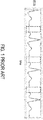
- An example of prospective gating for tomographic imaging is shown in FIG. 1 . It is noted that the projection images are acquired only during the period marked by dashed blocks. Accordingly, the acquired multi-angle projection images under the same physiological period are utilized for image reconstruction. Consequently, the tomographic images under the specific physiological state are obtained, and blurred images caused by movement on the tomographic images can be reduced.
- the disadvantage of this prospective gating technique is that the tomographic imaging system has to be connected with the external physiological monitoring apparatus, which increases the cost a lot.
- the projection images are acquired continuously. After the projection images are all collected, the projection images are processed according to the characteristics thereof. Particularly, the projection images under the same physiological state are selected. Accordingly, in the method for gating in tomographic imaging system of the present disclosure, there is no need to connect the tomographic imaging system with any external physiological monitoring apparatus.
- a method for gating in tomographic imaging system includes steps of: (a) performing a tomographic imaging on an object for acquiring a plurality of projection images at different angles, wherein a target of the object in the projection images moves periodically along a first axis; (b) obtaining a plurality of projected curves by summing up pixel values along a direction of a second axis, which is perpendicular to the first axis, in each of the projection images; (c) determining a target zone on the projection images, wherein the target is located in the target zone, and a central position on the first axis of the target zone is corresponding to a position having the largest variation in the projected curves on the first axis; (d) calculating parameter values of pixel values in the target zone on the projection images, and obtaining a curve of a moving cycle of the target according to the parameter values; and (e) selecting the projection images under the same state in the moving cycle
- the method for gating in tomographic imaging system of the present disclosure utilizes a retrospective gating technique.
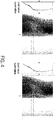
- the tomographic imaging is performed, as shown in FIG. 2 , the projection images are acquired continuously during the period marked by dashed block.
- the present disclosure utilizes the retrospective gated tomographic imaging system for gating to obviate blurred images caused by the periodical movement of the organs due to breath or heartbeat.
- the light source e.g., X-ray
- the detector are regularly moved around the detected object, so as to collect the projection images at different angles.
- the detected object is a living body, the organs of the detected object may move periodically due to breath or heartbeat. Therefore, the projection images at different angles are not static.
- the detected object is a mouse
- FIG. 3 shows the projection images of a mouse taken at different angles.
- the light source and the detector are rotated relative to the rotation axis which is depicted by the dashed line.
- the diaphragm of the mouse is located in the zone marked by the solid-line block, whose position is predetermined manually and needs to be further corrected. It is observed that the diaphragm moves upwardly or downwardly in different projection images due to breath.
- the position of the organ or zone affected by breathing on the projection image should be detected.
- the diaphragm as an example of a target that moves periodically in the detected object, the way of computing the position of the diaphragm is described as follows.
- the light source and the detector rotate around the rotation axis to perform the tomographic imaging for the detected object.
- the projection images at different angles are acquired continuously.
- the number of the projection images is N, being a positive integer, which can be determined according to the required image quality of the tomographic image formed based on the projection images. For example, the larger N is, the better the signal to noise ratio of the tomographic image is (i.e., the better the image quality of the tomographic image is).
- FIG. 4 schematically shows two projection images at two different angles. As shown in FIG.
- the rotation axis is parallel to a first axis s
- the diaphragm in the projection images moves upwardly or downwardly along the first axis s
- a second axis t is perpendicular to the first axis s.
- N projected curves C ⁇ ts are obtained by summing up the pixel values along the direction of the second axis t in every projection image.
- the difference between the first angle and the final angle is preferably but not limited to be larger than 180 degrees.
- T is the number of the pixels in the direction of the second axis t in the projection image.
- the projected curve is shown beside the corresponding projection image.
- the projected curve is a curve of the sum of the pixel values of each of the projection images versus the position along the first axis s.
- each point on the projected curve is corresponding to a pixel value summation and a position on the first axis s, where the said pixel value summation is the sum of the pixel values of all the pixels along the direction of the second axis t corresponding to the said position. That is, each of the projection images is projected along the first axis s to obtain the corresponding projected curve.
- the diaphragm zone has a central position on the first axis corresponding to a position having the largest variation in the projected curves on the first axis s.
- the projection image is regarded as a matrix of pixel values with a plurality of rows along the first axis s. The pixel values on each row are summed up to obtain the projected curve, and the row having the largest variation of the pixel value summation is the central position of the diaphragm zone.
- the coefficients of variation or the standard deviations along the time sequence are calculated, and the position on the first axis s having the largest coefficient of variation or the largest standard deviation is the central position on the first axis s of the diaphragm zone.
- the diaphragm zone in the projection image is marked automatically by a block, which is the solid-line block parallel to the second axis t.
- the dimension of the solid-line block is predetermined based on a general diaphragm size but not limited thereto.
- the respiration curve obtained in the succeeding steps can be more accurate.
- the parameter value e.g., maximum, minimum, average, median, summation or quartile
- the curve of the moving cycle of the diaphragm i.e. the respiration curve
- the curve of the moving cycle of the diaphragm is a graph of the parameter value versus time, or a graph of the parameter value versus a serial number of the projection images.
- the respiration curve can be obtained according to the parameter values of the N projection images taken at different angles.
- the projection images under the same state in the respiratory cycle i.e., the projection images taken at the same timing in the respiratory cycle
- the definition of the diaphragm tomographic image is improved.
- the projection images at the timing marked by the hollow circles are selected for image reconstruction, or the projection images at the timing marked by the solid circles are selected for image reconstruction.
- the transverse axis represents the time or the serial number of the projection images
- the vertical axis represents the parameter value of the pixel values.
- FIG. 6 is a schematic flow chart illustrating a method for gating in tomographic imaging system according to an embodiment of the present disclosure. Based on the above illustration, the method for gating in tomographic imaging system of the present disclosure can be generalized to include the steps shown in FIG. 6 .
- step S1 a tomographic imaging is performed on an object for acquiring a plurality of projection images at different angles.
- a target of the object in the projection images moves periodically along a first axis, which is parallel to a rotation axis of the light source and the detector.
- step S2 a plurality of projected curves are obtained by summing up the pixel values along the direction of a second axis, which is perpendicular to the first axis, in each of the projection images.
- a target zone on the projection images is determined.
- the target is located in the target zone, and a central position on the first axis of the target zone is corresponding to a position having the largest variation in the projected curves on the first axis.
- the coefficients of variation or the standard deviations along the time sequence are calculated, and the position having the largest coefficient of variation or the largest standard deviation is the central position of the target zone.
- step S4 the parameter value of the pixel values in the target zone on each projection image is calculated, and a curve of the moving cycle of the target is obtained according to the parameter values of the projection images.
- step S5 the projection images under the same state in the moving cycle are selected for image reconstruction according to the curve of the moving cycle of the target.
- the detected object is a living body
- the target is the diaphragm, which moves periodically due to breath.
- the projection images under the same state in the respiratory cycle are picked out for image reconstruction. Meanwhile, there is no need to connect the tomographic imaging system with any external physiological monitoring apparatus.
- the target may also be the heart, which moves periodically due to heartbeat, and the similar technique can also be applied to heart gating.
- the present disclosure provides a method for gating in tomographic imaging system.
- the projection images are acquired continuously. After the projection images are all collected, the projection images are processed according to the characteristics thereof. Particularly, the projection images under the same physiological state are picked out. Accordingly, in the method for gating in tomographic imaging system of the present disclosure, there is no need to connect the tomographic imaging system with any external physiological monitoring apparatus.
Landscapes
- Health & Medical Sciences (AREA)
- Engineering & Computer Science (AREA)
- Life Sciences & Earth Sciences (AREA)
- Medical Informatics (AREA)
- Physics & Mathematics (AREA)
- General Health & Medical Sciences (AREA)
- Nuclear Medicine, Radiotherapy & Molecular Imaging (AREA)
- Radiology & Medical Imaging (AREA)
- Pathology (AREA)
- Heart & Thoracic Surgery (AREA)
- Veterinary Medicine (AREA)
- High Energy & Nuclear Physics (AREA)
- Biophysics (AREA)
- Biomedical Technology (AREA)
- Optics & Photonics (AREA)
- Molecular Biology (AREA)
- Surgery (AREA)
- Animal Behavior & Ethology (AREA)
- Public Health (AREA)
- Computer Vision & Pattern Recognition (AREA)
- Theoretical Computer Science (AREA)
- General Physics & Mathematics (AREA)
- Physiology (AREA)
- Pulmonology (AREA)
- Chemical & Material Sciences (AREA)
- Analytical Chemistry (AREA)
- Biochemistry (AREA)
- Immunology (AREA)
- Quality & Reliability (AREA)
- Apparatus For Radiation Diagnosis (AREA)
Abstract
Description
- The present disclosure relates to a method for gating in tomographic imaging system, and more particularly to a method for image-based gating in tomographic imaging system.
- Tomographic imaging system includes computed tomography (CT), positron emission tomography (PET), and single photon emission computed tomography (SPECT), etc. When the CT scan is performed, the light source (e.g. X-ray) and the detector are regularly moved around the detected object to emit x-ray and acquire image data by 180 (or more, or less) degrees, so as to collect the projection images at different angles. Based on the projection images, an image reconstruction is performed by the computer, and the cross-sectional tomographic image of the detected object is formed. Further, the three-dimensional image of the detected object is formed by the multiple tomographic images.
- If the detected object is a living body, the organs (e.g. lung, heart) of the detected object may move periodically due to breath or heartbeat. Therefore, the organs of the detected object in the projection images at different angles are not static. Accordingly, the formed tomographic image would be blurred due to the movement of the organs.
- The gating technique is developed for obviating blurred images caused by the periodical movement of the organs. Conventionally, the gating technique is a prospective gating technique, which is illustrated as follows.
- In the prospective gating technique, the tomographic imaging system has to be connected with the external physiological monitoring apparatus, e.g., Electrocardiography (ECG) machine, piezoelectric sensor. The tomographic imaging system synchronizes with the physiological signal to acquire projection images in a specific state of period. An example of prospective gating for tomographic imaging is shown in
FIG. 1 . It is noted that the projection images are acquired only during the period marked by dashed blocks. Accordingly, the acquired multi-angle projection images under the same physiological period are utilized for image reconstruction. Consequently, the tomographic images under the specific physiological state are obtained, and blurred images caused by movement on the tomographic images can be reduced. However, the disadvantage of this prospective gating technique is that the tomographic imaging system has to be connected with the external physiological monitoring apparatus, which increases the cost a lot. In addition, it is also a technical challenge to synchronize the tomographic imaging system and the physiological monitoring apparatus. - Therefore, there is a need of providing a method for gating in tomographic imaging system to obviate the drawbacks encountered from the prior arts.
- It is an objective of the present disclosure to provide a method for gating in tomographic imaging system. When the tomographic imaging is performed, the projection images are acquired continuously. After the projection images are all collected, the projection images are processed according to the characteristics thereof. Particularly, the projection images under the same physiological state are selected. Accordingly, in the method for gating in tomographic imaging system of the present disclosure, there is no need to connect the tomographic imaging system with any external physiological monitoring apparatus.
- In accordance with an aspect of the present disclosure, there is provided a method for gating in tomographic imaging system. The method includes steps of: (a) performing a tomographic imaging on an object for acquiring a plurality of projection images at different angles, wherein a target of the object in the projection images moves periodically along a first axis; (b) obtaining a plurality of projected curves by summing up pixel values along a direction of a second axis, which is perpendicular to the first axis, in each of the projection images; (c) determining a target zone on the projection images, wherein the target is located in the target zone, and a central position on the first axis of the target zone is corresponding to a position having the largest variation in the projected curves on the first axis; (d) calculating parameter values of pixel values in the target zone on the projection images, and obtaining a curve of a moving cycle of the target according to the parameter values; and (e) selecting the projection images under the same state in the moving cycle for image reconstruction according to the curve of the moving cycle of the target.
-
-
FIG. 1 schematically shows the timing of performing tomographic imaging in the conventional prospective gating method; -
FIG. 2 schematically shows the timing of performing tomographic imaging in a method for gating of the present disclosure; -
FIG. 3 schematically shows the projection images taken at different angles; -
FIG. 4 schematically shows the projection images taken at different angles and the corresponding projected curves; -
FIG. 5 schematically shows the respiration curve obtained by the method for gating of the present disclosure; and -
FIG. 6 is a schematic flow chart illustrating a method for gating in tomographic imaging system according to an embodiment of the present disclosure. - The present disclosure will now be described more specifically with reference to the following embodiments. It is to be noted that the following descriptions of preferred embodiments of this disclosure are presented herein for purpose of illustration and description only. It is not intended to be exhaustive or to be limited to the precise form disclosed.
- The method for gating in tomographic imaging system of the present disclosure utilizes a retrospective gating technique. When the tomographic imaging is performed, as shown in
FIG. 2 , the projection images are acquired continuously during the period marked by dashed block. Particularly, the present disclosure utilizes the retrospective gated tomographic imaging system for gating to obviate blurred images caused by the periodical movement of the organs due to breath or heartbeat. - When the tomographic imaging is performed, the light source, e.g., X-ray, and the detector are regularly moved around the detected object, so as to collect the projection images at different angles. If the detected object is a living body, the organs of the detected object may move periodically due to breath or heartbeat. Therefore, the projection images at different angles are not static. For example, the detected object is a mouse, and
FIG. 3 shows the projection images of a mouse taken at different angles. The light source and the detector are rotated relative to the rotation axis which is depicted by the dashed line. The diaphragm of the mouse is located in the zone marked by the solid-line block, whose position is predetermined manually and needs to be further corrected. It is observed that the diaphragm moves upwardly or downwardly in different projection images due to breath. - In order to figure out the respiratory state to which every projection image is corresponding, the position of the organ or zone affected by breathing on the projection image should be detected. Taking the diaphragm as an example of a target that moves periodically in the detected object, the way of computing the position of the diaphragm is described as follows.
- The light source and the detector rotate around the rotation axis to perform the tomographic imaging for the detected object. When the tomographic imaging is performed, the projection images at different angles are acquired continuously. The number of the projection images is N, being a positive integer, which can be determined according to the required image quality of the tomographic image formed based on the projection images. For example, the larger N is, the better the signal to noise ratio of the tomographic image is (i.e., the better the image quality of the tomographic image is).
FIG. 4 schematically shows two projection images at two different angles. As shown inFIG. 4 , the rotation axis is parallel to a first axis s, the diaphragm in the projection images moves upwardly or downwardly along the first axis s, and a second axis t is perpendicular to the first axis s. - According to equation (1), in N projection images Pθts of different angles θ, N projected curves Cθts are obtained by summing up the pixel values along the direction of the second axis t in every projection image. In all the angles θ that the N projection images are taken at respectively, the difference between the first angle and the final angle is preferably but not limited to be larger than 180 degrees. Moreover, in equation (1), T is the number of the pixels in the direction of the second axis t in the projection image.

- Taking
FIG. 4 as an example, the projected curve is shown beside the corresponding projection image. The projected curve is a curve of the sum of the pixel values of each of the projection images versus the position along the first axis s. In particular, each point on the projected curve is corresponding to a pixel value summation and a position on the first axis s, where the said pixel value summation is the sum of the pixel values of all the pixels along the direction of the second axis t corresponding to the said position. That is, each of the projection images is projected along the first axis s to obtain the corresponding projected curve. - Then a diaphragm zone (target zone) where the diaphragm is located on the projection images is further determined. The diaphragm zone has a central position on the first axis corresponding to a position having the largest variation in the projected curves on the first axis s. For example, the projection image is regarded as a matrix of pixel values with a plurality of rows along the first axis s. The pixel values on each row are summed up to obtain the projected curve, and the row having the largest variation of the pixel value summation is the central position of the diaphragm zone. In an embodiment, in the N projected curves Cθts, the coefficients of variation or the standard deviations along the time sequence are calculated, and the position on the first axis s having the largest coefficient of variation or the largest standard deviation is the central position on the first axis s of the diaphragm zone. As shown in
FIG. 4 , the diaphragm zone in the projection image is marked automatically by a block, which is the solid-line block parallel to the second axis t. In specific, the dimension of the solid-line block is predetermined based on a general diaphragm size but not limited thereto. Once the central position of the diaphragm zone is determined, the diaphragm zone can be automatically marked by the block. - Since the detected object is always in the range of imaging during rotation, to sum up the pixel values along the second axis t can avoid the deviation caused by rotation. Therefore, the respiration curve obtained in the succeeding steps can be more accurate.
- After the diaphragm zone is determined, the parameter value (e.g., maximum, minimum, average, median, summation or quartile) of the pixel values in the diaphragm zone on the projection image is calculated. Then the curve of the moving cycle of the diaphragm, i.e. the respiration curve, is obtained according to the parameter values. For example, the curve of the moving cycle of the diaphragm is a graph of the parameter value versus time, or a graph of the parameter value versus a serial number of the projection images.
- As shown in
FIG. 5 , the respiration curve can be obtained according to the parameter values of the N projection images taken at different angles. The projection images under the same state in the respiratory cycle (i.e., the projection images taken at the same timing in the respiratory cycle) are selected for image reconstruction, and the definition of the diaphragm tomographic image is improved. For example, the projection images at the timing marked by the hollow circles are selected for image reconstruction, or the projection images at the timing marked by the solid circles are selected for image reconstruction. InFIG. 5 , the transverse axis represents the time or the serial number of the projection images, and the vertical axis represents the parameter value of the pixel values. -
FIG. 6 is a schematic flow chart illustrating a method for gating in tomographic imaging system according to an embodiment of the present disclosure. Based on the above illustration, the method for gating in tomographic imaging system of the present disclosure can be generalized to include the steps shown inFIG. 6 . - First, in step S1, a tomographic imaging is performed on an object for acquiring a plurality of projection images at different angles. A target of the object in the projection images moves periodically along a first axis, which is parallel to a rotation axis of the light source and the detector.
- Then, in step S2, a plurality of projected curves are obtained by summing up the pixel values along the direction of a second axis, which is perpendicular to the first axis, in each of the projection images.
- Then, in step S3, a target zone on the projection images is determined. The target is located in the target zone, and a central position on the first axis of the target zone is corresponding to a position having the largest variation in the projected curves on the first axis. In an embodiment, in the projected curves, the coefficients of variation or the standard deviations along the time sequence are calculated, and the position having the largest coefficient of variation or the largest standard deviation is the central position of the target zone.
- Afterward, in step S4, the parameter value of the pixel values in the target zone on each projection image is calculated, and a curve of the moving cycle of the target is obtained according to the parameter values of the projection images.
- Finally, in step S5, the projection images under the same state in the moving cycle are selected for image reconstruction according to the curve of the moving cycle of the target.
- In the embodiments shown in
FIGS. 2-5 , the detected object is a living body, and the target is the diaphragm, which moves periodically due to breath. Through the steps shown inFIG. 6 , the projection images under the same state in the respiratory cycle are picked out for image reconstruction. Meanwhile, there is no need to connect the tomographic imaging system with any external physiological monitoring apparatus. - In another embodiment, the target may also be the heart, which moves periodically due to heartbeat, and the similar technique can also be applied to heart gating.
- From the above descriptions, the present disclosure provides a method for gating in tomographic imaging system. When the tomographic imaging is performed, the projection images are acquired continuously. After the projection images are all collected, the projection images are processed according to the characteristics thereof. Particularly, the projection images under the same physiological state are picked out. Accordingly, in the method for gating in tomographic imaging system of the present disclosure, there is no need to connect the tomographic imaging system with any external physiological monitoring apparatus.
Claims (9)
- A method for gating in tomographic imaging system, characterized by comprising:(a) performing a tomographic imaging on an object for acquiring a plurality of projection images (Pθts) at different angles (θ), wherein a target of the object in the projection images (Pθts) moves periodically along a first axis (s);(b) obtaining a plurality of projected curves (Cθts) by summing up pixel values along a direction of a second axis (t), which is perpendicular to the first axis (s), in each of the projection images (Pθts);(c) determining a target zone on the projection images (Pθts), wherein the target is located in the target zone, and a central position on the first axis (s) of the target zone is corresponding to a position having a largest variation in the projected curves (Cθts) on the first axis (s);(d) calculating a parameter value of the pixel values in the target zone on each of the projection images (Pθts), and obtaining a curve of a moving cycle of the target according to the parameter values of the projection images; and(e) selecting the projection images (Pθts) under the same state in the moving cycle for image reconstruction according to the curve of the moving cycle of the target.
- The method according to claim 1, wherein the projected curve (Cθts) is obtained according to following equation:

- The method according to claim 1, wherein when the tomographic imaging is performed, a light source and a detector are regularly moved around the object for acquiring the projection images (Pθts) at the different angles (θ).
- The method according to claim 3, wherein the light source and the detector are rotated relative to a rotation axis parallel to the first axis (s).
- The method according to claim 1, wherein a number (N) of the projection images (Pθts) is determined according to a required image quality of a tomographic image formed based on the projection images (Pθts).
- The method according to claim 1, wherein each of the projection images (Pθts) is regarded as a matrix of pixel values with a plurality of rows along the first axis (s), the pixel values on each row are summed up, and the row having the largest variation of the sum of the pixel values in the projection images (Pθts) is the central position of the target zone.
- The method according to claim 1, wherein in the projected curves (Cθts), coefficients of variation or standard deviations along a time sequence are calculated, and a position on the first axis (s) having a largest coefficient of variation or the largest standard deviation corresponds to the central position on the first axis of the target zone.
- The method according to claim 1, wherein the parameter value is a maximum, a minimum, an average, a median, a summation or a quartile of the pixel values in the target zone.
- The method according to claim 1, wherein the curve of the moving cycle of the target is a graph of the parameter value versus time, or a graph of the parameter value versus a serial number of the projection images (Pθts).
Priority Applications (1)
| Application Number | Priority Date | Filing Date | Title |
|---|---|---|---|
| EP24181103.3A EP4406483A3 (en) | 2020-04-13 | 2021-03-24 | Method for gating in tomographic imaging system |
Applications Claiming Priority (2)
| Application Number | Priority Date | Filing Date | Title |
|---|---|---|---|
| US202063009168P | 2020-04-13 | 2020-04-13 | |
| US17/210,201 US11694374B2 (en) | 2020-04-13 | 2021-03-23 | Method for gating in tomographic imaging system |
Related Child Applications (2)
| Application Number | Title | Priority Date | Filing Date |
|---|---|---|---|
| EP24181103.3A Division-Into EP4406483A3 (en) | 2020-04-13 | 2021-03-24 | Method for gating in tomographic imaging system |
| EP24181103.3A Division EP4406483A3 (en) | 2020-04-13 | 2021-03-24 | Method for gating in tomographic imaging system |
Publications (2)
| Publication Number | Publication Date |
|---|---|
| EP3895620A1 true EP3895620A1 (en) | 2021-10-20 |
| EP3895620B1 EP3895620B1 (en) | 2024-09-25 |
Family
ID=75203164
Family Applications (2)
| Application Number | Title | Priority Date | Filing Date |
|---|---|---|---|
| EP24181103.3A Pending EP4406483A3 (en) | 2020-04-13 | 2021-03-24 | Method for gating in tomographic imaging system |
| EP21164530.4A Active EP3895620B1 (en) | 2020-04-13 | 2021-03-24 | Method for gating in tomographic imaging system |
Family Applications Before (1)
| Application Number | Title | Priority Date | Filing Date |
|---|---|---|---|
| EP24181103.3A Pending EP4406483A3 (en) | 2020-04-13 | 2021-03-24 | Method for gating in tomographic imaging system |
Country Status (6)
| Country | Link |
|---|---|
| US (2) | US11694374B2 (en) |
| EP (2) | EP4406483A3 (en) |
| JP (1) | JP7177882B2 (en) |
| CN (1) | CN113520432B (en) |
| ES (1) | ES2999674T3 (en) |
| TW (1) | TWI820411B (en) |
Families Citing this family (3)
| Publication number | Priority date | Publication date | Assignee | Title |
|---|---|---|---|---|
| EP3895621B1 (en) * | 2020-04-13 | 2024-08-21 | Delta Electronics, Inc. | Method for gating in tomographic imaging system |
| US20250139764A1 (en) * | 2023-10-31 | 2025-05-01 | GE Precision Healthcare LLC | System and method for motion guided retrospective gating |
| CN119112223A (en) * | 2024-08-15 | 2024-12-13 | 东软医疗系统股份有限公司 | Cardiac image scanning and reconstruction method and medical imaging equipment |
Citations (1)
| Publication number | Priority date | Publication date | Assignee | Title |
|---|---|---|---|---|
| WO2010025946A1 (en) * | 2008-09-08 | 2010-03-11 | Deutsches Krebsforschungszentrum Stiftung des öffentlichen Rechts | System and method for automated, intrinsic gated imaging |
Family Cites Families (25)
| Publication number | Priority date | Publication date | Assignee | Title |
|---|---|---|---|---|
| GB2408663B (en) * | 2003-11-28 | 2006-05-24 | Elekta Ab | Imaging internal structures |
| US7359535B2 (en) * | 2003-06-20 | 2008-04-15 | Ge Medical Systems Global Technology Company, Llc | Systems and methods for retrospective internal gating |
| US7477771B2 (en) | 2004-12-03 | 2009-01-13 | Genral Electric Company | Method and system for extracting information about the cardiac cycle from CT projection data |
| US8229187B2 (en) * | 2007-04-11 | 2012-07-24 | General Electric Company | Respiratory motion extraction from tomographic projection and image data |
| WO2008156764A1 (en) | 2007-06-15 | 2008-12-24 | The Johns Hopkins University | Methods for motion compensated image reconstruction and systems related thereto |
| DE102007053390A1 (en) | 2007-11-09 | 2008-12-18 | Siemens Ag | Method for producing temporal sequence of tomographic images to pre-determined phase position of cyclic moving object, for use with tomography equipment, involves capturing projections of z-positions in arranged sequence |
| CN101926676B (en) | 2009-06-25 | 2012-07-25 | 谢耀钦 | Medical images-tracking method capable of automatically identifying characteristic points and device thereof |
| JP5672147B2 (en) | 2011-05-24 | 2015-02-18 | コニカミノルタ株式会社 | Chest diagnosis support information generation system |
| EP2724319B1 (en) | 2011-06-21 | 2020-03-18 | Koninklijke Philips N.V. | Respiratory motion determination apparatus |
| CN103677226B (en) * | 2012-09-04 | 2016-08-03 | 北方工业大学 | Expression recognition input method |
| US20140341453A1 (en) * | 2013-05-17 | 2014-11-20 | Bailing Hsu | Myocardial blood flow quantitation with dynamic spect or spect/ct imaging |
| CN103759662B (en) * | 2013-12-31 | 2017-06-06 | 东华大学 | A kind of textile yarn diameter dynamic rapid measurement device and method |
| US9576391B2 (en) | 2014-02-21 | 2017-02-21 | Samsung Electronics Co., Ltd. | Tomography apparatus and method of reconstructing a tomography image by the tomography apparatus |
| WO2015200300A1 (en) * | 2014-06-23 | 2015-12-30 | University Of Maryland, Baltimore | Techniques for suppression of motion artifacts in medical imaging |
| CN104382613A (en) | 2014-12-02 | 2015-03-04 | 东南大学 | Full automatic inner retrospective CT respiratory gating system |
| CN105069785B (en) | 2015-07-29 | 2018-11-06 | 华北电力大学(保定) | A kind of retrospective off line respiration gate control method of sequence of heart images |
| KR101725891B1 (en) * | 2015-08-05 | 2017-04-11 | 삼성전자주식회사 | Tomography imaging apparatus and method for reconstructing a tomography image thereof |
| US20170055920A1 (en) | 2015-08-27 | 2017-03-02 | Xerox Corporation | Generating a respiration gating signal from a video |
| CN106570886B (en) * | 2016-10-27 | 2019-05-14 | 南京航空航天大学 | A target tracking method based on super-resolution reconstruction |
| CN208319362U (en) | 2017-01-20 | 2019-01-04 | 台达电子工业股份有限公司 | animal bed |
| JP7429120B2 (en) * | 2017-04-20 | 2024-02-07 | ザ クリーヴランド クリニック ファウンデーション | Non-vascular percutaneous procedure system and method for holographic image guidance |
| US10499867B2 (en) | 2018-01-08 | 2019-12-10 | Shenzhen Keya Medical Technology Corporation | Method, storage medium, and system for analyzing image sequences of periodic physiological activities |
| CN108634974B (en) * | 2018-04-03 | 2022-03-04 | 东软医疗系统股份有限公司 | A method and device for determining a gating signal |
| US20190370956A1 (en) | 2018-05-30 | 2019-12-05 | General Electric Company | Contrast imaging system and method |
| CN110197713B (en) * | 2019-05-10 | 2021-12-14 | 上海依智医疗技术有限公司 | Medical image processing method, device, equipment and medium |
-
2021
- 2021-03-23 US US17/210,201 patent/US11694374B2/en active Active
- 2021-03-24 EP EP24181103.3A patent/EP4406483A3/en active Pending
- 2021-03-24 ES ES21164530T patent/ES2999674T3/en active Active
- 2021-03-24 EP EP21164530.4A patent/EP3895620B1/en active Active
- 2021-04-08 CN CN202110376207.9A patent/CN113520432B/en active Active
- 2021-04-08 TW TW110112804A patent/TWI820411B/en active
- 2021-04-08 JP JP2021065995A patent/JP7177882B2/en active Active
-
2023
- 2023-05-16 US US18/198,056 patent/US11954768B2/en active Active
Patent Citations (1)
| Publication number | Priority date | Publication date | Assignee | Title |
|---|---|---|---|---|
| WO2010025946A1 (en) * | 2008-09-08 | 2010-03-11 | Deutsches Krebsforschungszentrum Stiftung des öffentlichen Rechts | System and method for automated, intrinsic gated imaging |
Non-Patent Citations (2)
| Title |
|---|
| HUGO GEOFFREY D. ET AL: "Advances in 4D radiation therapy for managing respiration: Part I - 4D imaging", ZEITSCHRIFT FUR MEDIZINISCHE PHYSIK, vol. 22, no. 4, 1 December 2012 (2012-12-01), DE, pages 258 - 271, XP055831573, ISSN: 0939-3889, DOI: 10.1016/j.zemedi.2012.06.009 * |
| MARTIN RACHAEL ET AL: "Evaluation of intrinsic respiratory signal determination methods for 4D CBCT adapted for mice", MEDICAL PHYSICS, AIP, MELVILLE, NY, US, vol. 42, no. 1, January 2015 (2015-01-01), pages 154 - 164, XP012193054, ISSN: 0094-2405, [retrieved on 19010101], DOI: 10.1118/1.4903264 * |
Also Published As
| Publication number | Publication date |
|---|---|
| CN113520432A (en) | 2021-10-22 |
| US20230290021A1 (en) | 2023-09-14 |
| EP3895620B1 (en) | 2024-09-25 |
| JP2021168914A (en) | 2021-10-28 |
| CN113520432B (en) | 2024-10-18 |
| JP7177882B2 (en) | 2022-11-24 |
| EP4406483A2 (en) | 2024-07-31 |
| TW202137936A (en) | 2021-10-16 |
| US11694374B2 (en) | 2023-07-04 |
| ES2999674T3 (en) | 2025-02-26 |
| EP4406483A3 (en) | 2024-10-09 |
| US11954768B2 (en) | 2024-04-09 |
| US20210319599A1 (en) | 2021-10-14 |
| TWI820411B (en) | 2023-11-01 |
Similar Documents
| Publication | Publication Date | Title |
|---|---|---|
| US11954768B2 (en) | Method for gating in tomographic imaging system | |
| CN104684482B (en) | Image processing device and X-ray CT device | |
| EP2982304B1 (en) | Medical image processing apparatus and medical image processing method | |
| EP1991959B1 (en) | Local motion compensation based on list mode data | |
| CN102125439B (en) | Image processing apparatus, X-ray computed tomography apparatus, and image processing method | |
| US8811707B2 (en) | System and method for distributed processing of tomographic images | |
| US10937209B2 (en) | Tomography imaging apparatus and method of reconstructing tomography image | |
| EP2521095B1 (en) | Dynamic error correction in radiographic imaging | |
| CN103608845B (en) | Respiratory movement determines device | |
| US20160098836A1 (en) | Image processing device and program | |
| US8659603B2 (en) | System and method for center point trajectory mapping | |
| US8487933B2 (en) | System and method for multi-segment center point trajectory mapping | |
| KR20190103816A (en) | Method and apparatus for correcting the computed tomographic image | |
| US11127153B2 (en) | Radiation imaging device, image processing method, and image processing program | |
| US20190133542A1 (en) | Systems and methods for data-driven respiratory gating in positron emission tomography | |
| US10852449B2 (en) | System and method for self-time alignment calibration for a positron emission tomography system | |
| KR20160119540A (en) | Tomography apparatus and method for processing a tomography image thereof | |
| Khurshid et al. | Automated cardiac motion compensation in PET/CT for accurate reconstruction of PET myocardial perfusion images | |
| US11806184B2 (en) | Method for gating in tomographic imaging system | |
| JP7379409B2 (en) | Gating method in tomographic imaging system | |
| CN118974773A (en) | Device-free motion state estimation | |
| US20250252621A1 (en) | Device-less motion state estimation | |
| WO2025214799A1 (en) | Processing projection data |
Legal Events
| Date | Code | Title | Description |
|---|---|---|---|
| PUAI | Public reference made under article 153(3) epc to a published international application that has entered the european phase |
Free format text: ORIGINAL CODE: 0009012 |
|
| STAA | Information on the status of an ep patent application or granted ep patent |
Free format text: STATUS: THE APPLICATION HAS BEEN PUBLISHED |
|
| AK | Designated contracting states |
Kind code of ref document: A1 Designated state(s): AL AT BE BG CH CY CZ DE DK EE ES FI FR GB GR HR HU IE IS IT LI LT LU LV MC MK MT NL NO PL PT RO RS SE SI SK SM TR |
|
| B565 | Issuance of search results under rule 164(2) epc |
Effective date: 20210823 |
|
| STAA | Information on the status of an ep patent application or granted ep patent |
Free format text: STATUS: REQUEST FOR EXAMINATION WAS MADE |
|
| 17P | Request for examination filed |
Effective date: 20220412 |
|
| RBV | Designated contracting states (corrected) |
Designated state(s): AL AT BE BG CH CY CZ DE DK EE ES FI FR GB GR HR HU IE IS IT LI LT LU LV MC MK MT NL NO PL PT RO RS SE SI SK SM TR |
|
| GRAP | Despatch of communication of intention to grant a patent |
Free format text: ORIGINAL CODE: EPIDOSNIGR1 |
|
| STAA | Information on the status of an ep patent application or granted ep patent |
Free format text: STATUS: GRANT OF PATENT IS INTENDED |
|
| INTG | Intention to grant announced |
Effective date: 20240422 |
|
| GRAS | Grant fee paid |
Free format text: ORIGINAL CODE: EPIDOSNIGR3 |
|
| GRAA | (expected) grant |
Free format text: ORIGINAL CODE: 0009210 |
|
| STAA | Information on the status of an ep patent application or granted ep patent |
Free format text: STATUS: THE PATENT HAS BEEN GRANTED |
|
| AK | Designated contracting states |
Kind code of ref document: B1 Designated state(s): AL AT BE BG CH CY CZ DE DK EE ES FI FR GB GR HR HU IE IS IT LI LT LU LV MC MK MT NL NO PL PT RO RS SE SI SK SM TR |
|
| REG | Reference to a national code |
Ref country code: GB Ref legal event code: FG4D |
|
| REG | Reference to a national code |
Ref country code: CH Ref legal event code: EP |
|
| P01 | Opt-out of the competence of the unified patent court (upc) registered |
Free format text: CASE NUMBER: APP_49945/2024 Effective date: 20240903 |
|
| REG | Reference to a national code |
Ref country code: DE Ref legal event code: R096 Ref document number: 602021019158 Country of ref document: DE |
|
| REG | Reference to a national code |
Ref country code: IE Ref legal event code: FG4D |
|
| REG | Reference to a national code |
Ref country code: NL Ref legal event code: FP |
|
| REG | Reference to a national code |
Ref country code: LT Ref legal event code: MG9D |
|
| PG25 | Lapsed in a contracting state [announced via postgrant information from national office to epo] |
Ref country code: NO Free format text: LAPSE BECAUSE OF FAILURE TO SUBMIT A TRANSLATION OF THE DESCRIPTION OR TO PAY THE FEE WITHIN THE PRESCRIBED TIME-LIMIT Effective date: 20241225 |
|
| PG25 | Lapsed in a contracting state [announced via postgrant information from national office to epo] |
Ref country code: GR Free format text: LAPSE BECAUSE OF FAILURE TO SUBMIT A TRANSLATION OF THE DESCRIPTION OR TO PAY THE FEE WITHIN THE PRESCRIBED TIME-LIMIT Effective date: 20241226 Ref country code: FI Free format text: LAPSE BECAUSE OF FAILURE TO SUBMIT A TRANSLATION OF THE DESCRIPTION OR TO PAY THE FEE WITHIN THE PRESCRIBED TIME-LIMIT Effective date: 20240925 |
|
| PG25 | Lapsed in a contracting state [announced via postgrant information from national office to epo] |
Ref country code: BG Free format text: LAPSE BECAUSE OF FAILURE TO SUBMIT A TRANSLATION OF THE DESCRIPTION OR TO PAY THE FEE WITHIN THE PRESCRIBED TIME-LIMIT Effective date: 20240925 |
|
| PG25 | Lapsed in a contracting state [announced via postgrant information from national office to epo] |
Ref country code: LV Free format text: LAPSE BECAUSE OF FAILURE TO SUBMIT A TRANSLATION OF THE DESCRIPTION OR TO PAY THE FEE WITHIN THE PRESCRIBED TIME-LIMIT Effective date: 20240925 |
|
| PG25 | Lapsed in a contracting state [announced via postgrant information from national office to epo] |
Ref country code: RS Free format text: LAPSE BECAUSE OF FAILURE TO SUBMIT A TRANSLATION OF THE DESCRIPTION OR TO PAY THE FEE WITHIN THE PRESCRIBED TIME-LIMIT Effective date: 20241225 |
|
| PG25 | Lapsed in a contracting state [announced via postgrant information from national office to epo] |
Ref country code: RS Free format text: LAPSE BECAUSE OF FAILURE TO SUBMIT A TRANSLATION OF THE DESCRIPTION OR TO PAY THE FEE WITHIN THE PRESCRIBED TIME-LIMIT Effective date: 20241225 Ref country code: NO Free format text: LAPSE BECAUSE OF FAILURE TO SUBMIT A TRANSLATION OF THE DESCRIPTION OR TO PAY THE FEE WITHIN THE PRESCRIBED TIME-LIMIT Effective date: 20241225 Ref country code: LV Free format text: LAPSE BECAUSE OF FAILURE TO SUBMIT A TRANSLATION OF THE DESCRIPTION OR TO PAY THE FEE WITHIN THE PRESCRIBED TIME-LIMIT Effective date: 20240925 Ref country code: GR Free format text: LAPSE BECAUSE OF FAILURE TO SUBMIT A TRANSLATION OF THE DESCRIPTION OR TO PAY THE FEE WITHIN THE PRESCRIBED TIME-LIMIT Effective date: 20241226 Ref country code: FI Free format text: LAPSE BECAUSE OF FAILURE TO SUBMIT A TRANSLATION OF THE DESCRIPTION OR TO PAY THE FEE WITHIN THE PRESCRIBED TIME-LIMIT Effective date: 20240925 Ref country code: BG Free format text: LAPSE BECAUSE OF FAILURE TO SUBMIT A TRANSLATION OF THE DESCRIPTION OR TO PAY THE FEE WITHIN THE PRESCRIBED TIME-LIMIT Effective date: 20240925 |
|
| REG | Reference to a national code |
Ref country code: AT Ref legal event code: MK05 Ref document number: 1725970 Country of ref document: AT Kind code of ref document: T Effective date: 20240925 |
|
| REG | Reference to a national code |
Ref country code: ES Ref legal event code: FG2A Ref document number: 2999674 Country of ref document: ES Kind code of ref document: T3 Effective date: 20250226 |
|
| PG25 | Lapsed in a contracting state [announced via postgrant information from national office to epo] |
Ref country code: IS Free format text: LAPSE BECAUSE OF FAILURE TO SUBMIT A TRANSLATION OF THE DESCRIPTION OR TO PAY THE FEE WITHIN THE PRESCRIBED TIME-LIMIT Effective date: 20250125 Ref country code: PT Free format text: LAPSE BECAUSE OF FAILURE TO SUBMIT A TRANSLATION OF THE DESCRIPTION OR TO PAY THE FEE WITHIN THE PRESCRIBED TIME-LIMIT Effective date: 20250127 |
|
| PG25 | Lapsed in a contracting state [announced via postgrant information from national office to epo] |
Ref country code: RO Free format text: LAPSE BECAUSE OF FAILURE TO SUBMIT A TRANSLATION OF THE DESCRIPTION OR TO PAY THE FEE WITHIN THE PRESCRIBED TIME-LIMIT Effective date: 20240925 Ref country code: SM Free format text: LAPSE BECAUSE OF FAILURE TO SUBMIT A TRANSLATION OF THE DESCRIPTION OR TO PAY THE FEE WITHIN THE PRESCRIBED TIME-LIMIT Effective date: 20240925 |
|
| PG25 | Lapsed in a contracting state [announced via postgrant information from national office to epo] |
Ref country code: EE Free format text: LAPSE BECAUSE OF FAILURE TO SUBMIT A TRANSLATION OF THE DESCRIPTION OR TO PAY THE FEE WITHIN THE PRESCRIBED TIME-LIMIT Effective date: 20240925 Ref country code: AT Free format text: LAPSE BECAUSE OF FAILURE TO SUBMIT A TRANSLATION OF THE DESCRIPTION OR TO PAY THE FEE WITHIN THE PRESCRIBED TIME-LIMIT Effective date: 20240925 |
|
| PG25 | Lapsed in a contracting state [announced via postgrant information from national office to epo] |
Ref country code: PL Free format text: LAPSE BECAUSE OF FAILURE TO SUBMIT A TRANSLATION OF THE DESCRIPTION OR TO PAY THE FEE WITHIN THE PRESCRIBED TIME-LIMIT Effective date: 20240925 Ref country code: CZ Free format text: LAPSE BECAUSE OF FAILURE TO SUBMIT A TRANSLATION OF THE DESCRIPTION OR TO PAY THE FEE WITHIN THE PRESCRIBED TIME-LIMIT Effective date: 20240925 |
|
| PG25 | Lapsed in a contracting state [announced via postgrant information from national office to epo] |
Ref country code: IT Free format text: LAPSE BECAUSE OF FAILURE TO SUBMIT A TRANSLATION OF THE DESCRIPTION OR TO PAY THE FEE WITHIN THE PRESCRIBED TIME-LIMIT Effective date: 20240925 Ref country code: SK Free format text: LAPSE BECAUSE OF FAILURE TO SUBMIT A TRANSLATION OF THE DESCRIPTION OR TO PAY THE FEE WITHIN THE PRESCRIBED TIME-LIMIT Effective date: 20240925 |
|
| REG | Reference to a national code |
Ref country code: DE Ref legal event code: R097 Ref document number: 602021019158 Country of ref document: DE |
|
| PG25 | Lapsed in a contracting state [announced via postgrant information from national office to epo] |
Ref country code: DK Free format text: LAPSE BECAUSE OF FAILURE TO SUBMIT A TRANSLATION OF THE DESCRIPTION OR TO PAY THE FEE WITHIN THE PRESCRIBED TIME-LIMIT Effective date: 20240925 |
|
| PGFP | Annual fee paid to national office [announced via postgrant information from national office to epo] |
Ref country code: ES Payment date: 20250408 Year of fee payment: 5 |
|
| PGFP | Annual fee paid to national office [announced via postgrant information from national office to epo] |
Ref country code: CH Payment date: 20250401 Year of fee payment: 5 |
|
| PLBE | No opposition filed within time limit |
Free format text: ORIGINAL CODE: 0009261 |
|
| STAA | Information on the status of an ep patent application or granted ep patent |
Free format text: STATUS: NO OPPOSITION FILED WITHIN TIME LIMIT |
|
| 26N | No opposition filed |
Effective date: 20250626 |
|
| PG25 | Lapsed in a contracting state [announced via postgrant information from national office to epo] |
Ref country code: SE Free format text: LAPSE BECAUSE OF FAILURE TO SUBMIT A TRANSLATION OF THE DESCRIPTION OR TO PAY THE FEE WITHIN THE PRESCRIBED TIME-LIMIT Effective date: 20240925 |
|
| PG25 | Lapsed in a contracting state [announced via postgrant information from national office to epo] |
Ref country code: MC Free format text: LAPSE BECAUSE OF FAILURE TO SUBMIT A TRANSLATION OF THE DESCRIPTION OR TO PAY THE FEE WITHIN THE PRESCRIBED TIME-LIMIT Effective date: 20240925 |
|
| PG25 | Lapsed in a contracting state [announced via postgrant information from national office to epo] |
Ref country code: LU Free format text: LAPSE BECAUSE OF NON-PAYMENT OF DUE FEES Effective date: 20250324 |
|
| PG25 | Lapsed in a contracting state [announced via postgrant information from national office to epo] |
Ref country code: HR Free format text: LAPSE BECAUSE OF FAILURE TO SUBMIT A TRANSLATION OF THE DESCRIPTION OR TO PAY THE FEE WITHIN THE PRESCRIBED TIME-LIMIT Effective date: 20240925 |
|
| PG25 | Lapsed in a contracting state [announced via postgrant information from national office to epo] |
Ref country code: IE Free format text: LAPSE BECAUSE OF NON-PAYMENT OF DUE FEES Effective date: 20250324 |
|
| PGFP | Annual fee paid to national office [announced via postgrant information from national office to epo] |
Ref country code: NL Payment date: 20260213 Year of fee payment: 6 |
|
| REG | Reference to a national code |
Ref country code: CH Ref legal event code: U11 Free format text: ST27 STATUS EVENT CODE: U-0-0-U10-U11 (AS PROVIDED BY THE NATIONAL OFFICE) Effective date: 20260401 |
|
| PGFP | Annual fee paid to national office [announced via postgrant information from national office to epo] |
Ref country code: GB Payment date: 20260202 Year of fee payment: 6 |
|
| PGFP | Annual fee paid to national office [announced via postgrant information from national office to epo] |
Ref country code: DE Payment date: 20260128 Year of fee payment: 6 |
|
| PGFP | Annual fee paid to national office [announced via postgrant information from national office to epo] |
Ref country code: BE Payment date: 20260216 Year of fee payment: 6 |
|
| PGFP | Annual fee paid to national office [announced via postgrant information from national office to epo] |
Ref country code: FR Payment date: 20260209 Year of fee payment: 6 |