EP3895594A1 - Household appliance comprising a heat pump, and method of operating such household appliance - Google Patents
Household appliance comprising a heat pump, and method of operating such household appliance Download PDFInfo
- Publication number
- EP3895594A1 EP3895594A1 EP21162838.3A EP21162838A EP3895594A1 EP 3895594 A1 EP3895594 A1 EP 3895594A1 EP 21162838 A EP21162838 A EP 21162838A EP 3895594 A1 EP3895594 A1 EP 3895594A1
- Authority
- EP
- European Patent Office
- Prior art keywords
- household appliance
- refrigerant
- heating device
- heat sink
- heat
- Prior art date
- Legal status (The legal status is an assumption and is not a legal conclusion. Google has not performed a legal analysis and makes no representation as to the accuracy of the status listed.)
- Granted
Links
Images


Classifications
-
- D—TEXTILES; PAPER
- D06—TREATMENT OF TEXTILES OR THE LIKE; LAUNDERING; FLEXIBLE MATERIALS NOT OTHERWISE PROVIDED FOR
- D06F—LAUNDERING, DRYING, IRONING, PRESSING OR FOLDING TEXTILE ARTICLES
- D06F58/00—Domestic laundry dryers
- D06F58/20—General details of domestic laundry dryers
- D06F58/206—Heat pump arrangements
-
- F—MECHANICAL ENGINEERING; LIGHTING; HEATING; WEAPONS; BLASTING
- F25—REFRIGERATION OR COOLING; COMBINED HEATING AND REFRIGERATION SYSTEMS; HEAT PUMP SYSTEMS; MANUFACTURE OR STORAGE OF ICE; LIQUEFACTION SOLIDIFICATION OF GASES
- F25B—REFRIGERATION MACHINES, PLANTS OR SYSTEMS; COMBINED HEATING AND REFRIGERATION SYSTEMS; HEAT PUMP SYSTEMS
- F25B30/00—Heat pumps
- F25B30/02—Heat pumps of the compression type
-
- A—HUMAN NECESSITIES
- A47—FURNITURE; DOMESTIC ARTICLES OR APPLIANCES; COFFEE MILLS; SPICE MILLS; SUCTION CLEANERS IN GENERAL
- A47L—DOMESTIC WASHING OR CLEANING; SUCTION CLEANERS IN GENERAL
- A47L15/00—Washing or rinsing machines for crockery or tableware
- A47L15/42—Details
- A47L15/4291—Recovery arrangements, e.g. for the recovery of energy or water
-
- F—MECHANICAL ENGINEERING; LIGHTING; HEATING; WEAPONS; BLASTING
- F24—HEATING; RANGES; VENTILATING
- F24H—FLUID HEATERS, e.g. WATER OR AIR HEATERS, HAVING HEAT-GENERATING MEANS, e.g. HEAT PUMPS, IN GENERAL
- F24H4/00—Fluid heaters characterised by the use of heat pumps
- F24H4/06—Air heaters
-
- F—MECHANICAL ENGINEERING; LIGHTING; HEATING; WEAPONS; BLASTING
- F25—REFRIGERATION OR COOLING; COMBINED HEATING AND REFRIGERATION SYSTEMS; HEAT PUMP SYSTEMS; MANUFACTURE OR STORAGE OF ICE; LIQUEFACTION SOLIDIFICATION OF GASES
- F25B—REFRIGERATION MACHINES, PLANTS OR SYSTEMS; COMBINED HEATING AND REFRIGERATION SYSTEMS; HEAT PUMP SYSTEMS
- F25B43/00—Arrangements for separating or purifying gases or liquids; Arrangements for vaporising the residuum of liquid refrigerant, e.g. by heat
- F25B43/006—Accumulators
-
- F—MECHANICAL ENGINEERING; LIGHTING; HEATING; WEAPONS; BLASTING
- F25—REFRIGERATION OR COOLING; COMBINED HEATING AND REFRIGERATION SYSTEMS; HEAT PUMP SYSTEMS; MANUFACTURE OR STORAGE OF ICE; LIQUEFACTION SOLIDIFICATION OF GASES
- F25B—REFRIGERATION MACHINES, PLANTS OR SYSTEMS; COMBINED HEATING AND REFRIGERATION SYSTEMS; HEAT PUMP SYSTEMS
- F25B49/00—Arrangement or mounting of control or safety devices
- F25B49/02—Arrangement or mounting of control or safety devices for compression type machines, plants or systems
-
- F—MECHANICAL ENGINEERING; LIGHTING; HEATING; WEAPONS; BLASTING
- F26—DRYING
- F26B—DRYING SOLID MATERIALS OR OBJECTS BY REMOVING LIQUID THEREFROM
- F26B21/00—Arrangements for supplying or controlling air or other gases for drying solid materials or objects
- F26B21/001—Air generating units, e.g. movable or independent of drying enclosure
-
- F—MECHANICAL ENGINEERING; LIGHTING; HEATING; WEAPONS; BLASTING
- F26—DRYING
- F26B—DRYING SOLID MATERIALS OR OBJECTS BY REMOVING LIQUID THEREFROM
- F26B21/00—Arrangements for supplying or controlling air or other gases for drying solid materials or objects
- F26B21/50—Ducting arrangements from the source of air or other gases to the materials or objects being dried
-
- A—HUMAN NECESSITIES
- A47—FURNITURE; DOMESTIC ARTICLES OR APPLIANCES; COFFEE MILLS; SPICE MILLS; SUCTION CLEANERS IN GENERAL
- A47L—DOMESTIC WASHING OR CLEANING; SUCTION CLEANERS IN GENERAL
- A47L15/00—Washing or rinsing machines for crockery or tableware
- A47L15/0018—Controlling processes, i.e. processes to control the operation of the machine characterised by the purpose or target of the control
- A47L15/0049—Detection or prevention of malfunction, including accident prevention
-
- A—HUMAN NECESSITIES
- A47—FURNITURE; DOMESTIC ARTICLES OR APPLIANCES; COFFEE MILLS; SPICE MILLS; SUCTION CLEANERS IN GENERAL
- A47L—DOMESTIC WASHING OR CLEANING; SUCTION CLEANERS IN GENERAL
- A47L2401/00—Automatic detection in controlling methods of washing or rinsing machines for crockery or tableware, e.g. information provided by sensors entered into controlling devices
- A47L2401/34—Other automatic detections
-
- A—HUMAN NECESSITIES
- A47—FURNITURE; DOMESTIC ARTICLES OR APPLIANCES; COFFEE MILLS; SPICE MILLS; SUCTION CLEANERS IN GENERAL
- A47L—DOMESTIC WASHING OR CLEANING; SUCTION CLEANERS IN GENERAL
- A47L2501/00—Output in controlling method of washing or rinsing machines for crockery or tableware, i.e. quantities or components controlled, or actions performed by the controlling device executing the controlling method
- A47L2501/36—Other output
-
- D—TEXTILES; PAPER
- D06—TREATMENT OF TEXTILES OR THE LIKE; LAUNDERING; FLEXIBLE MATERIALS NOT OTHERWISE PROVIDED FOR
- D06F—LAUNDERING, DRYING, IRONING, PRESSING OR FOLDING TEXTILE ARTICLES
- D06F2103/00—Parameters monitored or detected for the control of domestic laundry washing machines, washer-dryers or laundry dryers
- D06F2103/50—Parameters monitored or detected for the control of domestic laundry washing machines, washer-dryers or laundry dryers related to heat pumps, e.g. pressure or flow rate
-
- D—TEXTILES; PAPER
- D06—TREATMENT OF TEXTILES OR THE LIKE; LAUNDERING; FLEXIBLE MATERIALS NOT OTHERWISE PROVIDED FOR
- D06F—LAUNDERING, DRYING, IRONING, PRESSING OR FOLDING TEXTILE ARTICLES
- D06F2105/00—Systems or parameters controlled or affected by the control systems of washing machines, washer-dryers or laundry dryers
-
- D—TEXTILES; PAPER
- D06—TREATMENT OF TEXTILES OR THE LIKE; LAUNDERING; FLEXIBLE MATERIALS NOT OTHERWISE PROVIDED FOR
- D06F—LAUNDERING, DRYING, IRONING, PRESSING OR FOLDING TEXTILE ARTICLES
- D06F2105/00—Systems or parameters controlled or affected by the control systems of washing machines, washer-dryers or laundry dryers
- D06F2105/28—Electric heating
-
- D—TEXTILES; PAPER
- D06—TREATMENT OF TEXTILES OR THE LIKE; LAUNDERING; FLEXIBLE MATERIALS NOT OTHERWISE PROVIDED FOR
- D06F—LAUNDERING, DRYING, IRONING, PRESSING OR FOLDING TEXTILE ARTICLES
- D06F34/00—Details of control systems for washing machines, washer-dryers or laundry dryers
- D06F34/14—Arrangements for detecting or measuring specific parameters
-
- D—TEXTILES; PAPER
- D06—TREATMENT OF TEXTILES OR THE LIKE; LAUNDERING; FLEXIBLE MATERIALS NOT OTHERWISE PROVIDED FOR
- D06F—LAUNDERING, DRYING, IRONING, PRESSING OR FOLDING TEXTILE ARTICLES
- D06F58/00—Domestic laundry dryers
- D06F58/32—Control of operations performed in domestic laundry dryers
- D06F58/34—Control of operations performed in domestic laundry dryers characterised by the purpose or target of the control
- D06F58/50—Responding to irregular working conditions, e.g. malfunctioning of blowers
-
- F—MECHANICAL ENGINEERING; LIGHTING; HEATING; WEAPONS; BLASTING
- F25—REFRIGERATION OR COOLING; COMBINED HEATING AND REFRIGERATION SYSTEMS; HEAT PUMP SYSTEMS; MANUFACTURE OR STORAGE OF ICE; LIQUEFACTION SOLIDIFICATION OF GASES
- F25B—REFRIGERATION MACHINES, PLANTS OR SYSTEMS; COMBINED HEATING AND REFRIGERATION SYSTEMS; HEAT PUMP SYSTEMS
- F25B2400/00—Component parts or details not otherwise provided for in this subclass
- F25B2400/01—Heaters
-
- Y—GENERAL TAGGING OF NEW TECHNOLOGICAL DEVELOPMENTS; GENERAL TAGGING OF CROSS-SECTIONAL TECHNOLOGIES SPANNING OVER SEVERAL SECTIONS OF THE IPC; TECHNICAL SUBJECTS COVERED BY FORMER USPC CROSS-REFERENCE ART COLLECTIONS [XRACs] AND DIGESTS
- Y02—TECHNOLOGIES OR APPLICATIONS FOR MITIGATION OR ADAPTATION AGAINST CLIMATE CHANGE
- Y02B—CLIMATE CHANGE MITIGATION TECHNOLOGIES RELATED TO BUILDINGS, e.g. HOUSING, HOUSE APPLIANCES OR RELATED END-USER APPLICATIONS
- Y02B30/00—Energy efficient heating, ventilation or air conditioning [HVAC]
- Y02B30/52—Heat recovery pumps, i.e. heat pump based systems or units able to transfer the thermal energy from one area of the premises or part of the facilities to a different one, improving the overall efficiency
Definitions
- the invention relates to a household appliance comprising a heat pump having a closed refrigerant circuit for guiding a flow of a refrigerant, and integrated into the refrigerant circuit a heat source for providing heating by condensing the refrigerant, an expansion device for expanding the flow and located downstream of the heat source, a heat sink for providing cooling by evaporating the refrigerant, and located downstream of the expansion device, and a compressor system for driving and compressing the flow and located downstream of the heat sink and upstream of the heat source, the household appliance also comprising a control device for controlling operation of the household appliance and a heating device for providing heating to the heat pump.
- the invention also relates to a method of operating such household appliance.
- a heat pump of the generic type as defined above is disclosed in an article entitled “A combined Dual Hot-Gas Bypass Defrosting method with accumulator heater for an air-to-air heat pump in cold region” by Jaehong Kim et al., Applied Energy 147 (2013) 344-352 .
- the heat pump disclosed belongs to a climatization machine and is designed for enabling quick heating-up of the compressor system and the refrigerant circuit by bypassing the heat source, the expansion device, and the heat sink, and providing heating to the compressor system, upon start-up.
- the heat sink is provided for fully evaporating the refrigerant that enters it as a liquid or as a mixture of liquid and gas.
- the compressor system is also provided to compress the refrigerant in gaseous state only.
- a compressor system usually includes an accumulator which is a vessel for receiving refrigerant incoming from the heat sink and includes a siphon-like structure that retains any incoming liquid at least to some extent, and allows gaseous refrigerant only to proceed to the compressor. Yet such accumulator has a limited capacity for storing liquid refrigerant only.
- Adverse operating conditions particularly low ambient temperature, may lead to the accumulator being completely filled with liquid to its full capacity, so that liquid refrigerant may proceed to the compressor.
- the low compressibility of liquid refrigerant may impair operation of the compressor heavily, for example by explosive evaporation as the refrigerant is compressed, which is known as "slugging", and generates excessive operating noise and may even result in damage to the compressor.
- a measure known and widely used for keeping liquid refrigerant from reaching a compressor system is designing and allowing a heat sink to not only fully evaporate the refrigerant circulating therethrough but also heat the refrigerant to a temperature above the boiling temperature of the refrigerant under the pressure existent in the heat sink.
- Such measure is conventionally designated as "superheating” and is measured by determining the temperature difference between the actual temperature of the gaseous refrigerant and its boiling temperature at the given pressure in the heat sink. This temperature difference in designated as the "superheating temperature”.
- the superheating requires provision of related volume of the heat sink while it does not contribute much to the heat pumping process. Therefore there is a desire of keeping the superheating rather low. In its turn this makes the heat pump prone to impairing operation of the compressor system by accidentally incoming liquid refrigerant.
- the invention provides a household appliance comprising a heat pump having a closed refrigerant circuit for guiding a flow of a refrigerant, and integrated into the refrigerant circuit a heat source for providing heating by condensing the refrigerant, an expansion device for expanding the flow and located downstream of the heat source, a heat sink for providing cooling by evaporating the refrigerant, and located downstream of the expansion device, and a compressor system for driving and compressing the flow and located downstream of the heat sink and upstream of the heat source, the household appliance also comprising a control device for controlling operation of the household appliance and a heating device for providing heating to the heat pump, the household appliance which further comprises a sensor system for determining a superheating temperature of the refrigerant as it exits the heat sink, and the control device is connected to the sensor system and the heating device, and configured for operating the heating device in dependence of the superheating temperature.
- the invention also provides a method of operating a household appliance according to the invention wherein the sensor system is operated to continuously monitor the superheating temperature, and the heating device is engaged if the superheating temperature is lower than a predetermined threshold, and the heating device is disengaged if the superheating temperature is equal to or higher than the predetermined threshold.
- the invention accomplishes control of the flow of refrigerant to the compressor system by determining the superheating temperature of this flow, and controlling engagement of the heating device in dependence upon the superheating temperature.
- the invention introduces operation of a novel heating device into regular operation of a heat pump, by applying the heating device to controlling the superheating temperature as it is established in operating the heat pump according to its predetermined purpose.
- the invention may be applied advantageously in a heat pump wherein the superheating temperature is relatively low by design.
- the operating conditions may be controlled so as to preserve the design superheating temperature over a wide range of operating conditions, and ascertain keeping liquid refrigerant away from being subjected to compression.
- the invention may also be applied advantageously in a heat pump that is provided to operate under a large variation of operating conditions, including operation at rather low ambient temperatures - for example, temperatures under 10° C and even as low as 5° C. Also in such conditions the invention assists in controlling and preserving superheating temperature at a level sufficient to avoid liquid refrigerant from being subjected to compression, and slugging in the compressor system that is unacceptably noisy at best, and detrimental to the compressor system at worst.
- advantage may also be taken of reducing the volume of the accumulator that precedes the compressor in a heat pump's refrigerant circuit. Besides its phase separating and baffling function such accumulator is dead space from a thermodynamic point of view, and requires additional refrigerant to be entered into the refrigerant circuit. Such may be undesirable in view of saving unnecessary expense of climate-critical compounds such as fluorinated hydrocarbon compounds, and in view of requirements for extended fire protection when using a hydrocarbon such as propane (R290) as a refrigerant in an amount exceeding a legally prescribed limit.
- a hydrocarbon such as propane (R290)
- the sensor system is configured for determining the superheating temperature as a difference between an outlet temperature of the refrigerant at an outlet of the heat sink and an inlet temperature of the refrigerant at an inlet of the heat sink.
- a heat pump implementing the reverse Rankine cycle as presently operates the heat sink principally by evaporating the refrigerant which enters the heat sink as a dual-phase compound including both liquid as gaseous refrigerant. Disregarding any pressure drop caused by the flowing refrigerant such evaporation occurs at constant temperature.
- the sensor system comprises a first temperature sensor placed in the refrigerant circuit at the outlet, and a second temperature sensor placed in the refrigerant circuit at the inlet.
- control device is configured for having engaged the heating device if the superheating temperature is lower than a predetermined threshold and for having the heating device disengaged if the superheating temperature is equal to or higher than the predetermined threshold.
- the predetermined threshold is set at 5 K, emphasizing the fine control that the invention may apply, and also ascertaining that the heat sink needs not to be provided in excess dimensions for offering sufficient heating capability to obtain a sufficiently high superheating temperature.
- the heating device is arranged for providing heat to the heat sink, as a first alternative.
- a specific embodiment of the alternative is exhibited in the attached drawing and is described hereinbelow.
- the heating device is attached to the compressor system, as a second alternative.
- the function of heating the gaseous refrigerant is essentially assigned to one part of the heat pump, namely the compressor system.
- the compressor system comprises an accumulator for accumulating refrigerant received from the heat sink, and a compressor located downstream of the accumulator for driving and compressing the refrigerant, and wherein the heating device is arranged for providing heating to the accumulator.
- the accumulator is a natural selection for adding heating capability to evaporate liquid refrigerant that has been accumulating in the accumulator.
- the heating device includes an electric heater formed as a strip, particularly of metallic wire or tubing, and wound around the accumulator. This enables a retrofit to the accumulator which may be added to the accumulator after its complete manufacturing, and thereby enables application of more or less any pre-fabricated accumulator.
- the heating device is an induction heater and attached to a component of the heat pump selected from the group consisting of the heat sink and an accumulator and a compressor of the compression system, and wherein the component is made from ferromagnetic material.
- the heat pump is coupled to a process air circuit which circulates process air through a treatment chamber by a blower for being cyclically heated by the heat source and cooled by the heat sink, enabling application of the invention to various purposes that a household may provide, such as drying and climatising.
- This process air circuit may be closed, partly open, or fully open.
- the household appliance according to the previously defined embodiment of the invention is embodied as an appliance for drying household items placed in the treatment chamber.
- a first exemplary and preferred embodiment of such appliance for drying household items is a laundry treatment machine adapted for drying household items which are pieces of laundry.
- Such laundry treatment machine may be a dedicated laundry dryer, but it may also be a washer-dryer which is provided to provide both washing and drying operations for laundry treatment.
- a second exemplary and preferred embodiment of such appliance for drying household items is a dishwasher for washing and drying household items which are pieces of tableware.
- a household appliance 1 comprises a heat pump having a closed refrigerant circuit 2 for guiding a flow of a refrigerant, and integrated into the refrigerant circuit 2 a heat source 3 for providing heating by condensing the refrigerant, an expansion device 4 for expanding the flow and located downstream of the heat source 3, a heat sink 5 for providing cooling by evaporating the refrigerant, and located downstream of the expansion device 4, and a compressor system 6, 7 composed of an accumulator 6 and a compressor 7 for driving and compressing the flow and located downstream of the heat sink 5 and upstream of the heat source 3.
- heat pump has all features of the commonly known heat pump implementing the inverse Rankine cycle for pumping het from heat sink 4 to heat source 3.
- Both heat source 3 and heat sink 5 are heat exchangers, and provided for exchanging heat with process air flowing through.
- Heat sink 5 is particularly provided to extract humidity from the process air flowing through by cooling and condensation. This of course requires means for collecting condensate for disposal and associated to heat sink 5 suitably, but such means as commonly known are not shown in Fig. 1 for the sake of simplicity.
- Accumulator 6 serves as a reservoir for storing part of the refrigerant, and also as a phase separator for separating liquid refrigerant that enters accumulator 6 because of incomplete evaporation in heat sink 5 from gaseous refrigerant that desirably emerges from heat sink 5 only.
- Compressor 7 is provided to compress gaseous refrigerant; if liquid refrigerant enters compressor 7 it may evaporate uncontrollably during compression, causing excessive noise and possibly even damaging compressor 7 and other components of the heat pump. Accordingly accumulator 6 is shown, if only schematically, with a siphon-like structure and filled with liquid refrigerant to a certain level.
- the household appliance 1 of Fig. 1 also comprises a control device 8 for controlling operation of the household appliance 1.
- Control device 8 is shown as a black box in Fig. 1 . Connections between the control device 8 and other components of the household appliance 1 are also not shown for the sake of simplicity.
- Control device 8 includes functions of a display device providing operational information to a user, of an input device for receiving user's operational commands and data as possibly relating to selection of specific operational processes or operational parameters, and of a real control device for coordinating all components of household appliance 1 in performing their assigned functions in operating household appliance 1 according to user's needs and desires.
- the household appliance 1 of Fig. 1 further comprises a heating device 9 for providing heating to the heat pump.
- the household appliance 1 in addition comprises a sensor system 10, 11 including a first temperature sensor 10 placed in the refrigerant circuit 2 at an outlet of heat sink 5, and a second temperature sensor 11 placed in the refrigerant circuit 2 at an inlet of heat sink 5.
- Inlet and outlet of heat sink 5 may be determined by referring to the arrows composing refrigerant circuit 2, these arrows indicating directions of flow of the refrigerant.
- Sensor system 10, 11 is configured for determining the superheating temperature as a difference between an outlet temperature of the refrigerant at the outlet of heat sink 5 and the inlet temperature of the refrigerant at an inlet of the heat sink 5.
- control device 8 is connected to sensor system 10, 11 and heating device 9, and configured for operating heating device 9 in dependence of the superheating temperature.
- control device 8 is configured for having engaged heating device 9 if the superheating temperature is lower than a predetermined threshold and for having heating device 9 disengaged if the superheating temperature is equal to or higher than the predetermined threshold.
- This predetermined threshold is presently set at 5 K.
- Heating device 9 is engaged if the superheating temperature is lower than a predetermined threshold, and heating device 9 is disengaged if the superheating temperature is equal to or higher than the predetermined threshold.
- the predetermined threshold may be set as low as 5 K.
- heating device 9 may be arranged for providing heat to heat sink 5, Fig. 2 showing a section of a tube guiding refrigerant as part of heat sink 5, and heating device 9 formed by coiling a resistive heater formed as a metal strip, particularly a wire or tube, around heat sink 5's tube.
- heating device 9 may be attached to the compressor system 6, 7.
- the compressor system 6, 7 comprises an accumulator 6 for accumulating refrigerant received from heat sink 5, and a compressor 7 located downstream of accumulator 6 for driving and compressing the refrigerant.
- Heating device 9 is attached to accumulator 6 of which a cylindrical section is shown in Fig. 3 .
- Heating device 9 may be a resistive heater much similar to the one as shown in Fig. 2 , heating device 9 formed as a strip and wound around accumulator 6.
- heating device 9 of Fig. 3 is an induction heater 9, shown as a wire coil in Fig. 3 and providing energy to the ferromagnetic construction material of accumulator 6 through a variable magnetic field.
- induction heater 9 may be attached to any suitable component of the heat pump such as heat sink 5, accumulator 6, and compressor 7, as long as the selected component is made from ferromagnetic material.
- the heat pump is coupled to a process air circuit 13 which circulates process air through a treatment chamber 14 by a blower 12 for being cyclically heated by heat source 3 and cooled by the heat sink 5.
- Treatment chamber 14 has been left unspecified in Fig. 1 . Specific embodiments of treatment chamber 14 are shown in Figs. 4 and 5 .
- household appliance 1 is embodied as an appliance for drying household items 17, 19 placed in treatment chamber 14.
- household appliance 1 is embodied as a laundry treatment machine adapted for drying household items 17 which are pieces of laundry 17.
- treatment chamber 14 includes a drum 15 which is rotatable as shown by dashed arrow 16 for tumbling pieces of laundry 17 as they are dried by the process air flow traversing drum 15 as it is rotated.
- This household appliance 1 may be embodied as a laundry dryer 1 dedicated to drying laundry only, or as a washer-dryer which is provided both for washing and drying.
- household appliance 1 is embodied as a dishwasher for washing and drying household items 17, 19 which are pieces of tableware 19, and shown as plates 19 placed in Fig. 5 .
- Treatment chamber 14 is a washing compartment 18 wherein the plates 19 are placed upon a tray 20, and washed by spraying suds or water from a rotatable spray arm 21. Suds and water are indicated as dashed lines emerging from spray arm 21.
- Heating device 9 is engaged if the superheating temperature is lower than a predetermined threshold, and heating device 9 is disengaged if the superheating temperature is equal to or higher than the predetermined threshold.
- the predetermined threshold may be set as low as 5 K.
- the invention accomplishes control of the flow of refrigerant to compressor system 6, 7 by determining the superheating temperature of this flow, and controlling engagement of heating device 9 in dependence upon the superheating temperature.
- the invention introduces operation of a novel heating device 9 into regular operation of a heat pump, by applying heating device 9 to controlling the superheating temperature as it is established in operating the heat pump according to its predetermined purpose.
Landscapes
- Engineering & Computer Science (AREA)
- Mechanical Engineering (AREA)
- General Engineering & Computer Science (AREA)
- Physics & Mathematics (AREA)
- Thermal Sciences (AREA)
- Chemical & Material Sciences (AREA)
- Analytical Chemistry (AREA)
- Power Engineering (AREA)
- Combustion & Propulsion (AREA)
- Textile Engineering (AREA)
- Drying Of Solid Materials (AREA)
- Detail Structures Of Washing Machines And Dryers (AREA)
Abstract
Description
- The invention relates to a household appliance comprising a heat pump having a closed refrigerant circuit for guiding a flow of a refrigerant, and integrated into the refrigerant circuit a heat source for providing heating by condensing the refrigerant, an expansion device for expanding the flow and located downstream of the heat source, a heat sink for providing cooling by evaporating the refrigerant, and located downstream of the expansion device, and a compressor system for driving and compressing the flow and located downstream of the heat sink and upstream of the heat source, the household appliance also comprising a control device for controlling operation of the household appliance and a heating device for providing heating to the heat pump.
- The invention also relates to a method of operating such household appliance.
- A heat pump of the generic type as defined above is disclosed in an article entitled "A combined Dual Hot-Gas Bypass Defrosting method with accumulator heater for an air-to-air heat pump in cold region" by Jaehong Kim et al., Applied Energy 147 (2013) 344-352. The heat pump disclosed belongs to a climatization machine and is designed for enabling quick heating-up of the compressor system and the refrigerant circuit by bypassing the heat source, the expansion device, and the heat sink, and providing heating to the compressor system, upon start-up.
- In a heat pump as defined above the heat sink is provided for fully evaporating the refrigerant that enters it as a liquid or as a mixture of liquid and gas. The compressor system is also provided to compress the refrigerant in gaseous state only. For avoiding liquid refrigerant to reach a compressor in a compressor system a compressor system usually includes an accumulator which is a vessel for receiving refrigerant incoming from the heat sink and includes a siphon-like structure that retains any incoming liquid at least to some extent, and allows gaseous refrigerant only to proceed to the compressor. Yet such accumulator has a limited capacity for storing liquid refrigerant only. Adverse operating conditions, particularly low ambient temperature, may lead to the accumulator being completely filled with liquid to its full capacity, so that liquid refrigerant may proceed to the compressor. The low compressibility of liquid refrigerant may impair operation of the compressor heavily, for example by explosive evaporation as the refrigerant is compressed, which is known as "slugging", and generates excessive operating noise and may even result in damage to the compressor.
- A measure known and widely used for keeping liquid refrigerant from reaching a compressor system is designing and allowing a heat sink to not only fully evaporate the refrigerant circulating therethrough but also heat the refrigerant to a temperature above the boiling temperature of the refrigerant under the pressure existent in the heat sink. Such measure is conventionally designated as "superheating" and is measured by determining the temperature difference between the actual temperature of the gaseous refrigerant and its boiling temperature at the given pressure in the heat sink. This temperature difference in designated as the "superheating temperature". Yet, the superheating requires provision of related volume of the heat sink while it does not contribute much to the heat pumping process. Therefore there is a desire of keeping the superheating rather low. In its turn this makes the heat pump prone to impairing operation of the compressor system by accidentally incoming liquid refrigerant.
- It is an object of the invention to provide a household appliance of the generic type as defined above wherein precaution is taken for controlling the flow of refrigerant to the compressor system and improving protection from liquid refrigerant being compressed under adverse operating conditions.
- This problem is solved in accordance with the invention by providing a household appliance of the generic type as defined above and a method of operating such household appliance as defined in the respective independent claim.
- Accordingly the invention provides a household appliance comprising a heat pump having a closed refrigerant circuit for guiding a flow of a refrigerant, and integrated into the refrigerant circuit a heat source for providing heating by condensing the refrigerant, an expansion device for expanding the flow and located downstream of the heat source, a heat sink for providing cooling by evaporating the refrigerant, and located downstream of the expansion device, and a compressor system for driving and compressing the flow and located downstream of the heat sink and upstream of the heat source, the household appliance also comprising a control device for controlling operation of the household appliance and a heating device for providing heating to the heat pump, the household appliance which further comprises a sensor system for determining a superheating temperature of the refrigerant as it exits the heat sink, and the control device is connected to the sensor system and the heating device, and configured for operating the heating device in dependence of the superheating temperature.
- The invention also provides a method of operating a household appliance according to the invention wherein the sensor system is operated to continuously monitor the superheating temperature, and the heating device is engaged if the superheating temperature is lower than a predetermined threshold, and the heating device is disengaged if the superheating temperature is equal to or higher than the predetermined threshold.
- The invention accomplishes control of the flow of refrigerant to the compressor system by determining the superheating temperature of this flow, and controlling engagement of the heating device in dependence upon the superheating temperature. The invention introduces operation of a novel heating device into regular operation of a heat pump, by applying the heating device to controlling the superheating temperature as it is established in operating the heat pump according to its predetermined purpose.
- The invention may be applied advantageously in a heat pump wherein the superheating temperature is relatively low by design. In such heat pump the operating conditions may be controlled so as to preserve the design superheating temperature over a wide range of operating conditions, and ascertain keeping liquid refrigerant away from being subjected to compression.
- The invention may also be applied advantageously in a heat pump that is provided to operate under a large variation of operating conditions, including operation at rather low ambient temperatures - for example, temperatures under 10° C and even as low as 5° C. Also in such conditions the invention assists in controlling and preserving superheating temperature at a level sufficient to avoid liquid refrigerant from being subjected to compression, and slugging in the compressor system that is unacceptably noisy at best, and detrimental to the compressor system at worst.
- By applying the invention advantage may also be taken of reducing the volume of the accumulator that precedes the compressor in a heat pump's refrigerant circuit. Besides its phase separating and baffling function such accumulator is dead space from a thermodynamic point of view, and requires additional refrigerant to be entered into the refrigerant circuit. Such may be undesirable in view of saving unnecessary expense of climate-critical compounds such as fluorinated hydrocarbon compounds, and in view of requirements for extended fire protection when using a hydrocarbon such as propane (R290) as a refrigerant in an amount exceeding a legally prescribed limit.
- In accordance with a preferred embodiment of the invention the sensor system is configured for determining the superheating temperature as a difference between an outlet temperature of the refrigerant at an outlet of the heat sink and an inlet temperature of the refrigerant at an inlet of the heat sink. A heat pump implementing the reverse Rankine cycle as presently operates the heat sink principally by evaporating the refrigerant which enters the heat sink as a dual-phase compound including both liquid as gaseous refrigerant. Disregarding any pressure drop caused by the flowing refrigerant such evaporation occurs at constant temperature. Pickup of heat by the gaseous refrigerant is low in comparison to pickup of heat by phase transition from liquid to gas, implying that the temperature of the refrigerant will rise only gradually prior to exiting the heat sink. Yet, such rise of temperature which is conventionally termed as "superheating" is of some interest as it ascertains that the refrigerant is totally evaporated upon exiting the heat sink and entering the compressor system. Thus there is no danger that liquid refrigerant gets compressed which could result in rather quick, even explosive, evaporation which would generate both undesirable noise and undesirable mechanical strain to the compressor system and other components of the heat pump. Therefore controlling and preserving the superheating temperature is a powerful means for ascertaining smooth operation of a heat pump.
- In accordance with another preferred embodiment of the invention the sensor system comprises a first temperature sensor placed in the refrigerant circuit at the outlet, and a second temperature sensor placed in the refrigerant circuit at the inlet. Thereby simple means are applied to obtain the desired superheating temperature data.
- In accordance with a further preferred embodiment of the invention the control device is configured for having engaged the heating device if the superheating temperature is lower than a predetermined threshold and for having the heating device disengaged if the superheating temperature is equal to or higher than the predetermined threshold. Thereby the control of the superheating temperature is accomplished with simple and reliable means.
- In accordance with an additional preferred embodiment of the invention the predetermined threshold is set at 5 K, emphasizing the fine control that the invention may apply, and also ascertaining that the heat sink needs not to be provided in excess dimensions for offering sufficient heating capability to obtain a sufficiently high superheating temperature.
- In accordance with yet another preferred embodiment of the invention the heating device is arranged for providing heat to the heat sink, as a first alternative. A specific embodiment of the alternative is exhibited in the attached drawing and is described hereinbelow.
- In accordance with yet a further preferred embodiment of the invention the heating device is attached to the compressor system, as a second alternative. Thereby the function of heating the gaseous refrigerant is essentially assigned to one part of the heat pump, namely the compressor system.
- In accordance with a more preferred development of the previously defined embodiment of the invention the compressor system comprises an accumulator for accumulating refrigerant received from the heat sink, and a compressor located downstream of the accumulator for driving and compressing the refrigerant, and wherein the heating device is arranged for providing heating to the accumulator. Given the common function of the accumulator as a phase-separator the accumulator is a natural selection for adding heating capability to evaporate liquid refrigerant that has been accumulating in the accumulator.
- In accordance with an even more preferred development of the previously defined embodiment of the invention the heating device includes an electric heater formed as a strip, particularly of metallic wire or tubing, and wound around the accumulator. This enables a retrofit to the accumulator which may be added to the accumulator after its complete manufacturing, and thereby enables application of more or less any pre-fabricated accumulator.
- In accordance with yet an additional preferred embodiment of the invention the heating device is an induction heater and attached to a component of the heat pump selected from the group consisting of the heat sink and an accumulator and a compressor of the compression system, and wherein the component is made from ferromagnetic material. Thereby profit may by obtained by coupling the heating device to a component manufactured from a cheap and conventional material such as ferromagnetic steel, profiting also from the excellent controllability and variability of the inductive heat source, profiting further from the fact that the heat is generated as close as possible to the refrigerant which is to receive it in accordance with the invention, and profiting additionally from the absence of local hot spots as might occur with a conventional resistive heater.
- In accordance with still another preferred embodiment of the invention the heat pump is coupled to a process air circuit which circulates process air through a treatment chamber by a blower for being cyclically heated by the heat source and cooled by the heat sink, enabling application of the invention to various purposes that a household may provide, such as drying and climatising. This process air circuit may be closed, partly open, or fully open.
- In particular the household appliance according to the previously defined embodiment of the invention is embodied as an appliance for drying household items placed in the treatment chamber.
- A first exemplary and preferred embodiment of such appliance for drying household items is a laundry treatment machine adapted for drying household items which are pieces of laundry. Such laundry treatment machine may be a dedicated laundry dryer, but it may also be a washer-dryer which is provided to provide both washing and drying operations for laundry treatment. A second exemplary and preferred embodiment of such appliance for drying household items is a dishwasher for washing and drying household items which are pieces of tableware.
- Preferred embodiments will now be described with reference to the attached drawing wherein the Figures exhibit as follows:
- Fig. 1
- a schematic section through a household appliance;
- Fig. 2
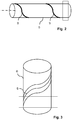
- a section of a heat sink with a heating device;
- Fig. 3
- a section of an accumulator with a heating device;
- Fig. 4
- a schematic section of a laundry dryer; and
- Fig. 5
- a schematic section of a dishwasher.
- According to
Fig. 1 a household appliance 1 comprises a heat pump having a closedrefrigerant circuit 2 for guiding a flow of a refrigerant, and integrated into the refrigerant circuit 2 aheat source 3 for providing heating by condensing the refrigerant, anexpansion device 4 for expanding the flow and located downstream of theheat source 3, aheat sink 5 for providing cooling by evaporating the refrigerant, and located downstream of theexpansion device 4, and acompressor system accumulator 6 and acompressor 7 for driving and compressing the flow and located downstream of theheat sink 5 and upstream of theheat source 3. Insofar the heat pump has all features of the commonly known heat pump implementing the inverse Rankine cycle for pumping het fromheat sink 4 to heatsource 3. Bothheat source 3 andheat sink 5 are heat exchangers, and provided for exchanging heat with process air flowing through.Heat sink 5 is particularly provided to extract humidity from the process air flowing through by cooling and condensation. This of course requires means for collecting condensate for disposal and associated toheat sink 5 suitably, but such means as commonly known are not shown inFig. 1 for the sake of simplicity. -
Accumulator 6 serves as a reservoir for storing part of the refrigerant, and also as a phase separator for separating liquid refrigerant that entersaccumulator 6 because of incomplete evaporation inheat sink 5 from gaseous refrigerant that desirably emerges fromheat sink 5 only.Compressor 7 is provided to compress gaseous refrigerant; if liquid refrigerant enterscompressor 7 it may evaporate uncontrollably during compression, causing excessive noise and possibly evendamaging compressor 7 and other components of the heat pump. Accordinglyaccumulator 6 is shown, if only schematically, with a siphon-like structure and filled with liquid refrigerant to a certain level. - The household appliance 1 of
Fig. 1 also comprises acontrol device 8 for controlling operation of the household appliance 1.Control device 8 is shown as a black box inFig. 1 . Connections between thecontrol device 8 and other components of the household appliance 1 are also not shown for the sake of simplicity.Control device 8 includes functions of a display device providing operational information to a user, of an input device for receiving user's operational commands and data as possibly relating to selection of specific operational processes or operational parameters, and of a real control device for coordinating all components of household appliance 1 in performing their assigned functions in operating household appliance 1 according to user's needs and desires. - The household appliance 1 of
Fig. 1 further comprises aheating device 9 for providing heating to the heat pump. The household appliance 1 in addition comprises asensor system first temperature sensor 10 placed in therefrigerant circuit 2 at an outlet ofheat sink 5, and asecond temperature sensor 11 placed in therefrigerant circuit 2 at an inlet ofheat sink 5. Inlet and outlet ofheat sink 5 may be determined by referring to the arrows composingrefrigerant circuit 2, these arrows indicating directions of flow of the refrigerant.Sensor system heat sink 5 and the inlet temperature of the refrigerant at an inlet of theheat sink 5. For determining the superheating temperature of the refrigerant as it exitsheat sink 5,control device 8 is connected tosensor system heating device 9, and configured for operatingheating device 9 in dependence of the superheating temperature. - Specifically control
device 8 is configured for having engagedheating device 9 if the superheating temperature is lower than a predetermined threshold and for havingheating device 9 disengaged if the superheating temperature is equal to or higher than the predetermined threshold. This predetermined threshold is presently set at 5 K. - As household appliance 1 is operated
sensor system Heating device 9 is engaged if the superheating temperature is lower than a predetermined threshold, andheating device 9 is disengaged if the superheating temperature is equal to or higher than the predetermined threshold. The predetermined threshold may be set as low as 5 K. - As shown in
Fig. 2 heating device 9 may be arranged for providing heat toheat sink 5,Fig. 2 showing a section of a tube guiding refrigerant as part ofheat sink 5, andheating device 9 formed by coiling a resistive heater formed as a metal strip, particularly a wire or tube, aroundheat sink 5's tube. - Alternatively and as shown in
Fig. 3 heating device 9 may be attached to thecompressor system compressor system accumulator 6 for accumulating refrigerant received fromheat sink 5, and acompressor 7 located downstream ofaccumulator 6 for driving and compressing the refrigerant.Heating device 9 is attached toaccumulator 6 of which a cylindrical section is shown inFig. 3 .Heating device 9 may be a resistive heater much similar to the one as shown inFig. 2 ,heating device 9 formed as a strip and wound aroundaccumulator 6. - With particular
preference heating device 9 ofFig. 3 is aninduction heater 9, shown as a wire coil inFig. 3 and providing energy to the ferromagnetic construction material ofaccumulator 6 through a variable magnetic field.Such induction heater 9 may be attached to any suitable component of the heat pump such asheat sink 5,accumulator 6, andcompressor 7, as long as the selected component is made from ferromagnetic material. - As already outlined with reference to
Fig. 1 the heat pump is coupled to aprocess air circuit 13 which circulates process air through atreatment chamber 14 by ablower 12 for being cyclically heated byheat source 3 and cooled by theheat sink 5.Treatment chamber 14 has been left unspecified inFig. 1 . Specific embodiments oftreatment chamber 14 are shown inFigs. 4 and 5 . - According to
Figs. 4 and 5 which present details of embodiments oftreatment chamber 14 household appliance 1 is embodied as an appliance for dryinghousehold items treatment chamber 14. - According to
Fig. 4 household appliance 1 is embodied as a laundry treatment machine adapted for dryinghousehold items 17 which are pieces oflaundry 17. To thisend treatment chamber 14 includes adrum 15 which is rotatable as shown by dashedarrow 16 for tumbling pieces oflaundry 17 as they are dried by the process airflow traversing drum 15 as it is rotated. This household appliance 1 may be embodied as a laundry dryer 1 dedicated to drying laundry only, or as a washer-dryer which is provided both for washing and drying. - According to
Fig. 5 household appliance 1 is embodied as a dishwasher for washing and dryinghousehold items tableware 19, and shown asplates 19 placed inFig. 5 .Treatment chamber 14 is awashing compartment 18 wherein theplates 19 are placed upon atray 20, and washed by spraying suds or water from arotatable spray arm 21. Suds and water are indicated as dashed lines emerging fromspray arm 21. - As household appliance 1 is operated
sensor system Heating device 9 is engaged if the superheating temperature is lower than a predetermined threshold, andheating device 9 is disengaged if the superheating temperature is equal to or higher than the predetermined threshold. The predetermined threshold may be set as low as 5 K. - The invention accomplishes control of the flow of refrigerant to
compressor system heating device 9 in dependence upon the superheating temperature. The invention introduces operation of anovel heating device 9 into regular operation of a heat pump, by applyingheating device 9 to controlling the superheating temperature as it is established in operating the heat pump according to its predetermined purpose. -
- 1
- Household appliance
- 2
- Refrigerant circuit
- 3
- Heat source
- 4
- Expansion device
- 5
- Heat sink
- 6
- Accumulator
- 7
- Compressor
- 8
- Control device
- 9
- Heating device
- 10
- First temperature sensor
- 11
- Second temperature sensor
- 12
- Blower
- 13
- Process Air circuit
- 14
- Treatment chamber
- 15
- Drum
- 16
- Dotted arrow
- 17
- Laundry
- 18
- Washing chamber
- 19
- Dish
- 20
- Tray
- 21
- Spray arm
Claims (17)
- A household appliance (1) comprising a heat pump having a closed refrigerant circuit (2) for guiding a flow of a refrigerant, and integrated into the refrigerant circuit (2) a heat source (3) for providing heating by condensing the refrigerant, an expansion device (4) for expanding the flow and located downstream of the heat source (3), a heat sink (5) for providing cooling by evaporating the refrigerant, and located downstream of the expansion device 4, and a compressor system (6, 7) for driving and compressing the flow and located downstream of the heat sink (5) and upstream of the heat source (3), the household appliance (1) also comprising a control device (8) for controlling operation of the household appliance (1) and a heating device (9) for providing heating to the heat pump, characterized in that the household appliance (1) further comprises a sensor system (10, 11) for determining a superheating temperature of the refrigerant as it exits the heat sink (5), and the control device (8) is connected to the sensor system (10, 11) and the heating device (9), and configured for operating the heating device (9) in dependence of the superheating temperature.
- The household appliance (1) according to claim 1, wherein the sensor system (10, 11) is configured for determining the superheating temperature as a difference between an outlet temperature of the refrigerant at an outlet of the heat sink (5) and an inlet temperature of the refrigerant at an inlet of the heat sink (5).
- The household appliance (1) according to claim 2, wherein the sensor system (10, 11) comprises a first temperature sensor (10) placed in the refrigerant circuit (2) at the outlet, and a second temperature sensor (11) placed in the refrigerant circuit (2) at the inlet.
- The household appliance (1) according to one of the preceding claims, wherein the control device (8) is configured for having engaged the heating device (9) if the superheating temperature is lower than a predetermined threshold and for having the heating device (9) disengaged if the superheating temperature is equal to or higher than the predetermined threshold.
- The household appliance (1) according to claim 4, wherein the predetermined threshold is set at 5 K.
- The household appliance (1) according to one of the preceding claims, wherein the heating device (9) is arranged for providing heat to the heat sink (5).
- The household appliance (1) according to one of the preceding claims, wherein the heating device (9) is attached to the compressor system (6, 7).
- The household appliance (1) according to claim 7, wherein the compressor system (6, 7) comprises an accumulator (6) for accumulating refrigerant received from the heat sink (5), and a compressor (7) located downstream of the accumulator (6) for driving and compressing the refrigerant, and wherein the heating device (9) is arranged for providing heating to the accumulator (6).
- The household appliance (1) according to claim 8, wherein the heating device (9) includes an electric heater formed as a strip and wound around the accumulator (6).
- The household appliance (1) according to one of the preceding claims, wherein the heating device (9) is an induction heater (9) and attached to a component of the heat pump selected from the group consisting of the heat sink (5) and an accumulator (6) and a compressor (7) of the compression system (6, 7), and wherein the component is made from ferromagnetic material.
- The household appliance (1) according to one of the preceding claims, wherein the heat pump is coupled to a process air circuit (13) which circulates process air through a treatment chamber (14) by a blower (12) for being cyclically heated by the heat source (3) and cooled by the heat sink (5).
- The household appliance (1) according to claim 11, which is embodied as an appliance for drying household items (17, 19) placed in the treatment chamber (14).
- The household appliance (1) according to claim 12, which is embodied as a laundry treatment machine adapted for drying household items (17, 19) which are pieces of laundry (17).
- The household appliance (1) according to claim 13, which is embodied as a laundry dryer.
- The household appliance (1) according to claim 12, which is embodied as a dishwasher for washing and drying household items (17, 19) which are pieces of tableware (19).
- A method of operating a household appliance (1) according to one of the preceding claims, wherein the sensor system (10, 11) is operated to continuously monitor the superheating temperature, and the heating device (9) is engaged if the superheating temperature is lower than a predetermined threshold, and the heating device (9) is disengaged if the superheating temperature is equal to or higher than the predetermined threshold.
- The method according to claim 16, wherein the predetermined threshold is set at 5 K.
Applications Claiming Priority (1)
| Application Number | Priority Date | Filing Date | Title |
|---|---|---|---|
| EP20382314 | 2020-04-17 |
Publications (2)
| Publication Number | Publication Date |
|---|---|
| EP3895594A1 true EP3895594A1 (en) | 2021-10-20 |
| EP3895594B1 EP3895594B1 (en) | 2023-11-08 |
Family
ID=70391048
Family Applications (1)
| Application Number | Title | Priority Date | Filing Date |
|---|---|---|---|
| EP21162838.3A Active EP3895594B1 (en) | 2020-04-17 | 2021-03-16 | Household appliance comprising a heat pump, and method of operating such household appliance |
Country Status (3)
| Country | Link |
|---|---|
| EP (1) | EP3895594B1 (en) |
| CN (1) | CN113531952A (en) |
| PL (1) | PL3895594T3 (en) |
Cited By (1)
| Publication number | Priority date | Publication date | Assignee | Title |
|---|---|---|---|---|
| CN119412841A (en) * | 2024-12-04 | 2025-02-11 | 湖南翔润环保科技有限公司 | An air heat pump suitable for low temperature environment |
Citations (5)
| Publication number | Priority date | Publication date | Assignee | Title |
|---|---|---|---|---|
| WO2005031231A1 (en) * | 2003-09-25 | 2005-04-07 | Matsushita Electric Industrial Co. Ltd. | Heat pump type drying apparatus drying apparatus and drying method |
| EP2468945A1 (en) * | 2010-12-27 | 2012-06-27 | Electrolux Home Products Corporation N.V. | Home laundry dryer with heat pump assembly |
| WO2013045363A1 (en) * | 2011-09-27 | 2013-04-04 | Arcelik Anonim Sirketi | Heat pump laundry dryer |
| EP2728052A1 (en) * | 2012-10-30 | 2014-05-07 | Electrolux Home Products Corporation N.V. | Washing machine |
| WO2014146704A1 (en) * | 2013-03-20 | 2014-09-25 | Electrolux Appliances Aktiebolag | Appliance for drying laundry |
Family Cites Families (5)
| Publication number | Priority date | Publication date | Assignee | Title |
|---|---|---|---|---|
| CN102175052B (en) * | 2008-03-18 | 2014-03-12 | Lg电子株式会社 | Air conditioner and control method thereof |
| CN203629167U (en) * | 2013-06-13 | 2014-06-04 | 广东美的暖通设备有限公司 | Gas-liquid separation device and air conditioner |
| CN203514074U (en) * | 2013-06-26 | 2014-04-02 | 上海日立电器有限公司 | Heat pump type drying and dehumidification system for clothes dryer |
| JP2015224845A (en) * | 2014-05-29 | 2015-12-14 | パナソニックIpマネジメント株式会社 | Refrigeration cycle device |
| CN106524389B (en) * | 2015-09-15 | 2020-11-10 | 上海海立电器有限公司 | A kind of air conditioner defrosting method and air conditioner thereof |
-
2021
- 2021-03-16 PL PL21162838.3T patent/PL3895594T3/en unknown
- 2021-03-16 EP EP21162838.3A patent/EP3895594B1/en active Active
- 2021-04-15 CN CN202110408298.XA patent/CN113531952A/en active Pending
Patent Citations (5)
| Publication number | Priority date | Publication date | Assignee | Title |
|---|---|---|---|---|
| WO2005031231A1 (en) * | 2003-09-25 | 2005-04-07 | Matsushita Electric Industrial Co. Ltd. | Heat pump type drying apparatus drying apparatus and drying method |
| EP2468945A1 (en) * | 2010-12-27 | 2012-06-27 | Electrolux Home Products Corporation N.V. | Home laundry dryer with heat pump assembly |
| WO2013045363A1 (en) * | 2011-09-27 | 2013-04-04 | Arcelik Anonim Sirketi | Heat pump laundry dryer |
| EP2728052A1 (en) * | 2012-10-30 | 2014-05-07 | Electrolux Home Products Corporation N.V. | Washing machine |
| WO2014146704A1 (en) * | 2013-03-20 | 2014-09-25 | Electrolux Appliances Aktiebolag | Appliance for drying laundry |
Non-Patent Citations (1)
| Title |
|---|
| JAEHONG KIM ET AL.: "A combined Dual Hot-Gas Bypass Defrosting method with accumulator heater for an air-to-air heat pump in cold region", APPLIED ENERGY, vol. 147, 2013, pages 344 - 352 |
Cited By (1)
| Publication number | Priority date | Publication date | Assignee | Title |
|---|---|---|---|---|
| CN119412841A (en) * | 2024-12-04 | 2025-02-11 | 湖南翔润环保科技有限公司 | An air heat pump suitable for low temperature environment |
Also Published As
| Publication number | Publication date |
|---|---|
| EP3895594B1 (en) | 2023-11-08 |
| PL3895594T3 (en) | 2024-03-18 |
| CN113531952A (en) | 2021-10-22 |
Similar Documents
| Publication | Publication Date | Title |
|---|---|---|
| EP2640885B1 (en) | Machine comprising a heat pump and related set of processes | |
| EP2513368B1 (en) | Household appliance comprising an expansion system | |
| EP2489774B1 (en) | A heat pump laundry dryer | |
| Mancini et al. | Thermodynamic analysis and experimental investigation of a CO2 household heat pump dryer | |
| KR102364677B1 (en) | Control Method for Laundry Treating Apparatus | |
| EA016181B1 (en) | Household appliance containing a heat transfer fluid | |
| US20160160429A1 (en) | Laundry Treatment Apparatus and Method for Operating a Laundry Treatment Apparatus | |
| EP3895594B1 (en) | Household appliance comprising a heat pump, and method of operating such household appliance | |
| JP2010270928A (en) | Vacuum drying apparatus and vacuum drying method | |
| EP2831330B1 (en) | Heat pump for a clothes treatment appliance, and clothes treatment appliance comprising such heat pump | |
| WO2013014137A1 (en) | A heat pump system for a laundry dryer | |
| CN114606738A (en) | Clothes dryer and heat pump system and control method thereof | |
| WO2013075997A1 (en) | A laundry dryer with a heat pump system | |
| CN105121730A (en) | Appliance for drying laundry | |
| EP2644768A1 (en) | Heat pump for a clothes treatment appliance | |
| US20160298280A1 (en) | Clothes dryer with improved refrigerant circuit | |
| EP2412868A1 (en) | Machine and process for drying humid articles with superheating a refrigerant | |
| EP3115500A1 (en) | Household appliance for drying articles | |
| CN117626610A (en) | Heat pump system, heat pump clothes dryer and control method thereof | |
| EP2690380A1 (en) | Apparatus including a heat pump and method to operate an apparatus including the heat pump | |
| JP7647786B2 (en) | Refrigeration Cycle Equipment | |
| AU2019208187A1 (en) | Laundry Dryer including a Heat Pump System | |
| Tang et al. | Performance investigation of a constant temperature heat pump dryer | |
| WO2013064236A1 (en) | A laundry dryer with a heat pump system and air recirculation | |
| CN117702435A (en) | Heat pump drying system, liquid return prevention control method thereof, heat pump clothes dryer and medium |
Legal Events
| Date | Code | Title | Description |
|---|---|---|---|
| PUAI | Public reference made under article 153(3) epc to a published international application that has entered the european phase |
Free format text: ORIGINAL CODE: 0009012 |
|
| STAA | Information on the status of an ep patent application or granted ep patent |
Free format text: STATUS: THE APPLICATION HAS BEEN PUBLISHED |
|
| AK | Designated contracting states |
Kind code of ref document: A1 Designated state(s): AL AT BE BG CH CY CZ DE DK EE ES FI FR GB GR HR HU IE IS IT LI LT LU LV MC MK MT NL NO PL PT RO RS SE SI SK SM TR |
|
| B565 | Issuance of search results under rule 164(2) epc |
Effective date: 20210824 |
|
| STAA | Information on the status of an ep patent application or granted ep patent |
Free format text: STATUS: REQUEST FOR EXAMINATION WAS MADE |
|
| 17P | Request for examination filed |
Effective date: 20220420 |
|
| RBV | Designated contracting states (corrected) |
Designated state(s): AL AT BE BG CH CY CZ DE DK EE ES FI FR GB GR HR HU IE IS IT LI LT LU LV MC MK MT NL NO PL PT RO RS SE SI SK SM TR |
|
| GRAP | Despatch of communication of intention to grant a patent |
Free format text: ORIGINAL CODE: EPIDOSNIGR1 |
|
| STAA | Information on the status of an ep patent application or granted ep patent |
Free format text: STATUS: GRANT OF PATENT IS INTENDED |
|
| INTG | Intention to grant announced |
Effective date: 20230707 |
|
| RIC1 | Information provided on ipc code assigned before grant |
Ipc: D06F 105/28 20200101ALN20230623BHEP Ipc: D06F 105/00 20200101ALN20230623BHEP Ipc: D06F 103/50 20200101ALN20230623BHEP Ipc: A47L 15/00 20060101ALN20230623BHEP Ipc: D06F 58/20 20060101ALI20230623BHEP Ipc: A47L 15/42 20060101AFI20230623BHEP |
|
| GRAS | Grant fee paid |
Free format text: ORIGINAL CODE: EPIDOSNIGR3 |
|
| GRAA | (expected) grant |
Free format text: ORIGINAL CODE: 0009210 |
|
| STAA | Information on the status of an ep patent application or granted ep patent |
Free format text: STATUS: THE PATENT HAS BEEN GRANTED |
|
| AK | Designated contracting states |
Kind code of ref document: B1 Designated state(s): AL AT BE BG CH CY CZ DE DK EE ES FI FR GB GR HR HU IE IS IT LI LT LU LV MC MK MT NL NO PL PT RO RS SE SI SK SM TR |
|
| REG | Reference to a national code |
Ref country code: GB Ref legal event code: FG4D |
|
| REG | Reference to a national code |
Ref country code: CH Ref legal event code: EP |
|
| REG | Reference to a national code |
Ref country code: DE Ref legal event code: R096 Ref document number: 602021006532 Country of ref document: DE |
|
| REG | Reference to a national code |
Ref country code: IE Ref legal event code: FG4D |
|
| REG | Reference to a national code |
Ref country code: LT Ref legal event code: MG9D |
|
| REG | Reference to a national code |
Ref country code: NL Ref legal event code: MP Effective date: 20231108 |
|
| PG25 | Lapsed in a contracting state [announced via postgrant information from national office to epo] |
Ref country code: GR Free format text: LAPSE BECAUSE OF FAILURE TO SUBMIT A TRANSLATION OF THE DESCRIPTION OR TO PAY THE FEE WITHIN THE PRESCRIBED TIME-LIMIT Effective date: 20240209 |
|
| PG25 | Lapsed in a contracting state [announced via postgrant information from national office to epo] |
Ref country code: IS Free format text: LAPSE BECAUSE OF FAILURE TO SUBMIT A TRANSLATION OF THE DESCRIPTION OR TO PAY THE FEE WITHIN THE PRESCRIBED TIME-LIMIT Effective date: 20240308 |
|
| PG25 | Lapsed in a contracting state [announced via postgrant information from national office to epo] |
Ref country code: LT Free format text: LAPSE BECAUSE OF FAILURE TO SUBMIT A TRANSLATION OF THE DESCRIPTION OR TO PAY THE FEE WITHIN THE PRESCRIBED TIME-LIMIT Effective date: 20231108 |
|
| REG | Reference to a national code |
Ref country code: AT Ref legal event code: MK05 Ref document number: 1628866 Country of ref document: AT Kind code of ref document: T Effective date: 20231108 |
|
| PG25 | Lapsed in a contracting state [announced via postgrant information from national office to epo] |
Ref country code: NL Free format text: LAPSE BECAUSE OF FAILURE TO SUBMIT A TRANSLATION OF THE DESCRIPTION OR TO PAY THE FEE WITHIN THE PRESCRIBED TIME-LIMIT Effective date: 20231108 |
|
| PG25 | Lapsed in a contracting state [announced via postgrant information from national office to epo] |
Ref country code: AT Free format text: LAPSE BECAUSE OF FAILURE TO SUBMIT A TRANSLATION OF THE DESCRIPTION OR TO PAY THE FEE WITHIN THE PRESCRIBED TIME-LIMIT Effective date: 20231108 |
|
| PG25 | Lapsed in a contracting state [announced via postgrant information from national office to epo] |
Ref country code: ES Free format text: LAPSE BECAUSE OF FAILURE TO SUBMIT A TRANSLATION OF THE DESCRIPTION OR TO PAY THE FEE WITHIN THE PRESCRIBED TIME-LIMIT Effective date: 20231108 |
|
| PG25 | Lapsed in a contracting state [announced via postgrant information from national office to epo] |
Ref country code: NL Free format text: LAPSE BECAUSE OF FAILURE TO SUBMIT A TRANSLATION OF THE DESCRIPTION OR TO PAY THE FEE WITHIN THE PRESCRIBED TIME-LIMIT Effective date: 20231108 Ref country code: LT Free format text: LAPSE BECAUSE OF FAILURE TO SUBMIT A TRANSLATION OF THE DESCRIPTION OR TO PAY THE FEE WITHIN THE PRESCRIBED TIME-LIMIT Effective date: 20231108 Ref country code: IS Free format text: LAPSE BECAUSE OF FAILURE TO SUBMIT A TRANSLATION OF THE DESCRIPTION OR TO PAY THE FEE WITHIN THE PRESCRIBED TIME-LIMIT Effective date: 20240308 Ref country code: GR Free format text: LAPSE BECAUSE OF FAILURE TO SUBMIT A TRANSLATION OF THE DESCRIPTION OR TO PAY THE FEE WITHIN THE PRESCRIBED TIME-LIMIT Effective date: 20240209 Ref country code: ES Free format text: LAPSE BECAUSE OF FAILURE TO SUBMIT A TRANSLATION OF THE DESCRIPTION OR TO PAY THE FEE WITHIN THE PRESCRIBED TIME-LIMIT Effective date: 20231108 Ref country code: BG Free format text: LAPSE BECAUSE OF FAILURE TO SUBMIT A TRANSLATION OF THE DESCRIPTION OR TO PAY THE FEE WITHIN THE PRESCRIBED TIME-LIMIT Effective date: 20240208 Ref country code: AT Free format text: LAPSE BECAUSE OF FAILURE TO SUBMIT A TRANSLATION OF THE DESCRIPTION OR TO PAY THE FEE WITHIN THE PRESCRIBED TIME-LIMIT Effective date: 20231108 Ref country code: PT Free format text: LAPSE BECAUSE OF FAILURE TO SUBMIT A TRANSLATION OF THE DESCRIPTION OR TO PAY THE FEE WITHIN THE PRESCRIBED TIME-LIMIT Effective date: 20240308 |
|
| PG25 | Lapsed in a contracting state [announced via postgrant information from national office to epo] |
Ref country code: SE Free format text: LAPSE BECAUSE OF FAILURE TO SUBMIT A TRANSLATION OF THE DESCRIPTION OR TO PAY THE FEE WITHIN THE PRESCRIBED TIME-LIMIT Effective date: 20231108 Ref country code: RS Free format text: LAPSE BECAUSE OF FAILURE TO SUBMIT A TRANSLATION OF THE DESCRIPTION OR TO PAY THE FEE WITHIN THE PRESCRIBED TIME-LIMIT Effective date: 20231108 Ref country code: NO Free format text: LAPSE BECAUSE OF FAILURE TO SUBMIT A TRANSLATION OF THE DESCRIPTION OR TO PAY THE FEE WITHIN THE PRESCRIBED TIME-LIMIT Effective date: 20240208 Ref country code: LV Free format text: LAPSE BECAUSE OF FAILURE TO SUBMIT A TRANSLATION OF THE DESCRIPTION OR TO PAY THE FEE WITHIN THE PRESCRIBED TIME-LIMIT Effective date: 20231108 Ref country code: HR Free format text: LAPSE BECAUSE OF FAILURE TO SUBMIT A TRANSLATION OF THE DESCRIPTION OR TO PAY THE FEE WITHIN THE PRESCRIBED TIME-LIMIT Effective date: 20231108 |
|
| PG25 | Lapsed in a contracting state [announced via postgrant information from national office to epo] |
Ref country code: DK Free format text: LAPSE BECAUSE OF FAILURE TO SUBMIT A TRANSLATION OF THE DESCRIPTION OR TO PAY THE FEE WITHIN THE PRESCRIBED TIME-LIMIT Effective date: 20231108 |
|
| PG25 | Lapsed in a contracting state [announced via postgrant information from national office to epo] |
Ref country code: CZ Free format text: LAPSE BECAUSE OF FAILURE TO SUBMIT A TRANSLATION OF THE DESCRIPTION OR TO PAY THE FEE WITHIN THE PRESCRIBED TIME-LIMIT Effective date: 20231108 |
|
| PG25 | Lapsed in a contracting state [announced via postgrant information from national office to epo] |
Ref country code: SK Free format text: LAPSE BECAUSE OF FAILURE TO SUBMIT A TRANSLATION OF THE DESCRIPTION OR TO PAY THE FEE WITHIN THE PRESCRIBED TIME-LIMIT Effective date: 20231108 |
|
| PG25 | Lapsed in a contracting state [announced via postgrant information from national office to epo] |
Ref country code: SM Free format text: LAPSE BECAUSE OF FAILURE TO SUBMIT A TRANSLATION OF THE DESCRIPTION OR TO PAY THE FEE WITHIN THE PRESCRIBED TIME-LIMIT Effective date: 20231108 Ref country code: SK Free format text: LAPSE BECAUSE OF FAILURE TO SUBMIT A TRANSLATION OF THE DESCRIPTION OR TO PAY THE FEE WITHIN THE PRESCRIBED TIME-LIMIT Effective date: 20231108 Ref country code: RO Free format text: LAPSE BECAUSE OF FAILURE TO SUBMIT A TRANSLATION OF THE DESCRIPTION OR TO PAY THE FEE WITHIN THE PRESCRIBED TIME-LIMIT Effective date: 20231108 Ref country code: IT Free format text: LAPSE BECAUSE OF FAILURE TO SUBMIT A TRANSLATION OF THE DESCRIPTION OR TO PAY THE FEE WITHIN THE PRESCRIBED TIME-LIMIT Effective date: 20231108 Ref country code: EE Free format text: LAPSE BECAUSE OF FAILURE TO SUBMIT A TRANSLATION OF THE DESCRIPTION OR TO PAY THE FEE WITHIN THE PRESCRIBED TIME-LIMIT Effective date: 20231108 Ref country code: DK Free format text: LAPSE BECAUSE OF FAILURE TO SUBMIT A TRANSLATION OF THE DESCRIPTION OR TO PAY THE FEE WITHIN THE PRESCRIBED TIME-LIMIT Effective date: 20231108 Ref country code: CZ Free format text: LAPSE BECAUSE OF FAILURE TO SUBMIT A TRANSLATION OF THE DESCRIPTION OR TO PAY THE FEE WITHIN THE PRESCRIBED TIME-LIMIT Effective date: 20231108 |
|
| REG | Reference to a national code |
Ref country code: DE Ref legal event code: R097 Ref document number: 602021006532 Country of ref document: DE |
|
| PLBE | No opposition filed within time limit |
Free format text: ORIGINAL CODE: 0009261 |
|
| STAA | Information on the status of an ep patent application or granted ep patent |
Free format text: STATUS: NO OPPOSITION FILED WITHIN TIME LIMIT |
|
| 26N | No opposition filed |
Effective date: 20240809 |
|
| PG25 | Lapsed in a contracting state [announced via postgrant information from national office to epo] |
Ref country code: SI Free format text: LAPSE BECAUSE OF FAILURE TO SUBMIT A TRANSLATION OF THE DESCRIPTION OR TO PAY THE FEE WITHIN THE PRESCRIBED TIME-LIMIT Effective date: 20231108 |
|
| PG25 | Lapsed in a contracting state [announced via postgrant information from national office to epo] |
Ref country code: SI Free format text: LAPSE BECAUSE OF FAILURE TO SUBMIT A TRANSLATION OF THE DESCRIPTION OR TO PAY THE FEE WITHIN THE PRESCRIBED TIME-LIMIT Effective date: 20231108 |
|
| REG | Reference to a national code |
Ref country code: CH Ref legal event code: PL |
|
| PG25 | Lapsed in a contracting state [announced via postgrant information from national office to epo] |
Ref country code: LU Free format text: LAPSE BECAUSE OF NON-PAYMENT OF DUE FEES Effective date: 20240316 |
|
| PG25 | Lapsed in a contracting state [announced via postgrant information from national office to epo] |
Ref country code: MC Free format text: LAPSE BECAUSE OF FAILURE TO SUBMIT A TRANSLATION OF THE DESCRIPTION OR TO PAY THE FEE WITHIN THE PRESCRIBED TIME-LIMIT Effective date: 20231108 |
|
| PG25 | Lapsed in a contracting state [announced via postgrant information from national office to epo] |
Ref country code: MC Free format text: LAPSE BECAUSE OF FAILURE TO SUBMIT A TRANSLATION OF THE DESCRIPTION OR TO PAY THE FEE WITHIN THE PRESCRIBED TIME-LIMIT Effective date: 20231108 Ref country code: LU Free format text: LAPSE BECAUSE OF NON-PAYMENT OF DUE FEES Effective date: 20240316 |
|
| REG | Reference to a national code |
Ref country code: BE Ref legal event code: MM Effective date: 20240331 |
|
| PG25 | Lapsed in a contracting state [announced via postgrant information from national office to epo] |
Ref country code: BE Free format text: LAPSE BECAUSE OF NON-PAYMENT OF DUE FEES Effective date: 20240331 |
|
| PG25 | Lapsed in a contracting state [announced via postgrant information from national office to epo] |
Ref country code: FR Free format text: LAPSE BECAUSE OF NON-PAYMENT OF DUE FEES Effective date: 20240331 |
|
| PG25 | Lapsed in a contracting state [announced via postgrant information from national office to epo] |
Ref country code: IE Free format text: LAPSE BECAUSE OF NON-PAYMENT OF DUE FEES Effective date: 20240316 |
|
| PG25 | Lapsed in a contracting state [announced via postgrant information from national office to epo] |
Ref country code: FR Free format text: LAPSE BECAUSE OF NON-PAYMENT OF DUE FEES Effective date: 20240331 Ref country code: BE Free format text: LAPSE BECAUSE OF NON-PAYMENT OF DUE FEES Effective date: 20240331 Ref country code: IE Free format text: LAPSE BECAUSE OF NON-PAYMENT OF DUE FEES Effective date: 20240316 Ref country code: CH Free format text: LAPSE BECAUSE OF NON-PAYMENT OF DUE FEES Effective date: 20240331 |
|
| PG25 | Lapsed in a contracting state [announced via postgrant information from national office to epo] |
Ref country code: CY Free format text: LAPSE BECAUSE OF FAILURE TO SUBMIT A TRANSLATION OF THE DESCRIPTION OR TO PAY THE FEE WITHIN THE PRESCRIBED TIME-LIMIT; INVALID AB INITIO Effective date: 20210316 |
|
| PG25 | Lapsed in a contracting state [announced via postgrant information from national office to epo] |
Ref country code: HU Free format text: LAPSE BECAUSE OF FAILURE TO SUBMIT A TRANSLATION OF THE DESCRIPTION OR TO PAY THE FEE WITHIN THE PRESCRIBED TIME-LIMIT; INVALID AB INITIO Effective date: 20210316 |
|
| PG25 | Lapsed in a contracting state [announced via postgrant information from national office to epo] |
Ref country code: FI Free format text: LAPSE BECAUSE OF FAILURE TO SUBMIT A TRANSLATION OF THE DESCRIPTION OR TO PAY THE FEE WITHIN THE PRESCRIBED TIME-LIMIT Effective date: 20231108 |
|
| GBPC | Gb: european patent ceased through non-payment of renewal fee |
Effective date: 20250316 |
|
| PG25 | Lapsed in a contracting state [announced via postgrant information from national office to epo] |
Ref country code: GB Free format text: LAPSE BECAUSE OF NON-PAYMENT OF DUE FEES Effective date: 20250316 |
|
| PGFP | Annual fee paid to national office [announced via postgrant information from national office to epo] |
Ref country code: DE Payment date: 20260331 Year of fee payment: 6 |
|
| PGFP | Annual fee paid to national office [announced via postgrant information from national office to epo] |
Ref country code: TR Payment date: 20260306 Year of fee payment: 6 |
|
| PGFP | Annual fee paid to national office [announced via postgrant information from national office to epo] |
Ref country code: PL Payment date: 20260309 Year of fee payment: 6 |