EP3895518A1 - Grain measuring device, combine, field management system - Google Patents
Grain measuring device, combine, field management system Download PDFInfo
- Publication number
- EP3895518A1 EP3895518A1 EP20749646.4A EP20749646A EP3895518A1 EP 3895518 A1 EP3895518 A1 EP 3895518A1 EP 20749646 A EP20749646 A EP 20749646A EP 3895518 A1 EP3895518 A1 EP 3895518A1
- Authority
- EP
- European Patent Office
- Prior art keywords
- grains
- reaping
- combine harvester
- measuring device
- position information
- Prior art date
- Legal status (The legal status is an assumption and is not a legal conclusion. Google has not performed a legal analysis and makes no representation as to the accuracy of the status listed.)
- Granted
Links
Images


Classifications
-
- A—HUMAN NECESSITIES
- A01—AGRICULTURE; FORESTRY; ANIMAL HUSBANDRY; HUNTING; TRAPPING; FISHING
- A01D—HARVESTING; MOWING
- A01D41/00—Combines, i.e. harvesters or mowers combined with threshing devices
- A01D41/12—Details of combines
- A01D41/127—Control or measuring arrangements specially adapted for combines
- A01D41/1277—Control or measuring arrangements specially adapted for combines for measuring grain quality
-
- A—HUMAN NECESSITIES
- A01—AGRICULTURE; FORESTRY; ANIMAL HUSBANDRY; HUNTING; TRAPPING; FISHING
- A01D—HARVESTING; MOWING
- A01D41/00—Combines, i.e. harvesters or mowers combined with threshing devices
- A01D41/12—Details of combines
- A01D41/127—Control or measuring arrangements specially adapted for combines
- A01D41/1271—Control or measuring arrangements specially adapted for combines for measuring crop flow
-
- A—HUMAN NECESSITIES
- A01—AGRICULTURE; FORESTRY; ANIMAL HUSBANDRY; HUNTING; TRAPPING; FISHING
- A01D—HARVESTING; MOWING
- A01D41/00—Combines, i.e. harvesters or mowers combined with threshing devices
- A01D41/12—Details of combines
- A01D41/127—Control or measuring arrangements specially adapted for combines
-
- G—PHYSICS
- G06—COMPUTING OR CALCULATING; COUNTING
- G06V—IMAGE OR VIDEO RECOGNITION OR UNDERSTANDING
- G06V20/00—Scenes; Scene-specific elements
- G06V20/40—Scenes; Scene-specific elements in video content
- G06V20/44—Event detection
-
- G—PHYSICS
- G06—COMPUTING OR CALCULATING; COUNTING
- G06V—IMAGE OR VIDEO RECOGNITION OR UNDERSTANDING
- G06V20/00—Scenes; Scene-specific elements
- G06V20/60—Type of objects
- G06V20/68—Food, e.g. fruit or vegetables
-
- A—HUMAN NECESSITIES
- A01—AGRICULTURE; FORESTRY; ANIMAL HUSBANDRY; HUNTING; TRAPPING; FISHING
- A01B—SOIL WORKING IN AGRICULTURE OR FORESTRY; PARTS, DETAILS, OR ACCESSORIES OF AGRICULTURAL MACHINES OR IMPLEMENTS, IN GENERAL
- A01B79/00—Methods for working soil
- A01B79/005—Precision agriculture
Definitions
- the present disclosure relates to a grain measuring device such as what is called a "protein sensor", a combine harvester including the grain measuring device, and a field management system using the grain measuring device.
- a grain measuring device such as what is called a "protein sensor”
- a combine harvester including the grain measuring device
- a field management system using the grain measuring device.
- the information on the harvest points of the crops and the data on the measured nutritional values are associated with each other to create a map representing the distribution of fertility in the field and control the growth of the crops. For example, based on this map, additional fertilization, pesticide spraying, or other measures are taken to make the fertility uniform. This reliably provides crops uniform in quality at a stable yield.
- a sensor i.e., a protein sensor that measures the content of protein among the nutrients contained in the crops, namely, grains.
- the measurement data is acquired also at the time of reaping no grains, which requires an enormous data capacity for storing the measurement results.
- the measurement results include the measurement data obtained while reaping no grains. This requires extra work such as removing such data to create a fertility map of the field, which degrades the work efficiency.
- the present disclosure was made to solve the problems. It is an objective of the present disclosure to provide a grain measuring device, a combine harvester, and a field management system capable of improving the accuracy in measuring grains and the efficiency in data processing.
- a grain measuring device located in a combine harvester that reaps grains using a cutter and harvests the grains.
- the grain measuring device includes: a reaping determination unit configured to determine whether the combine harvester is in a state of reaping the grains; and a measurement unit configured to measure a component of the grains and save a result of measurement when the reaping determination unit determines that the combine harvester is in the state of reaping the grains.
- the reaping determination unit determines whether the combine harvester is in the state of reaping the grains based on a cutting position or a standby position of the cutter.
- the reaping determination unit determines the state of reaping the grains by detecting collision of kernels conveyed in the combine harvester.
- the reaping determination unit captures an image of an inside of a path for conveying the kernels in the combine harvester, and determines the state of reaping the grains based on the image captured.
- the reaping determination unit further includes:
- a combine harvester includes the grain measuring device described above.
- a field management system uses a grain measuring device in a combine harvester that reaps grains using a cutter and harvests the grains.
- the field management system includes: the grain measuring device including a reaping determination unit configured to determine whether the combine harvester is in a state of reaping the grains, a measurement unit configured to measure a component of the grains and save a result of measurement when the reaping determination unit determines that the combine harvester is in the state of reaping the grains, a position information acquisition unit capable of acquiring position information, and a storage unit configured to store the position information acquired by the position information acquisition unit and information on the component of the grains measured by the measurement unit; and a field evaluation unit configured to generate, for a field harvested by the combine harvester, a component distribution of the grains in the field based on the position information and the information on the component of the grains stored in the storage unit.
- the present disclosure using the unit described above improves the accuracy in measuring grains and the efficiency in data processing.
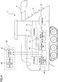
- FIG. 1 shows a schematic configuration diagram of a combine harvester including a grain measuring device according to this embodiment. With reference to the diagram, the configuration according to the embodiment of the present invention will be described below.
- a combine harvester 1 is a crawler traveling, head feed combine harvester capable of self-traveling with a pair of right and left crawlers that are driven by an engine (not shown).
- Examples of the grains to be reaped and harvested by the combine harvester include grass such as wheat and rice.
- This combine harvester 1 includes, at the front of the vehicle body, a cutter 3 movable up and down by a driver 2.
- the driver 2 is a hydraulic actuator, for example, movable up and down with respect to the cutter 3 between a cutting position indicated by a dotted line in FIG. 1 and a standby position indicated by a solid line.
- the cutter 3 cuts the straw of grains to be planted in a field and supplies the cut straw to a thresher 5 via a first conveyor 4.
- the cutter 3 includes a cutting blade and a receiving blade like a hair clipper (not shown), and cuts the crops at a height near the ground through the reciprocating motion of the cutting blade.
- the combine harvester 1 lifts the cutter 3 up to the standby position not to hinder the travel while reaping no grains, and down to the cutting position when reaping grains.
- Such lift up and down of the cutter 3 through the driver 2 can be operated by a lifting lever (not shown).
- the driver 2 moves up and down in accordance with a binary drive signal transmitted from a control unit (not shown), for example, at 0 V when lifting up the cutter 3 and at 5 V when lifting down the cutter 3. When the drive signal indicates 5 V, it is thus determined that the cutter 3 is at the cutting position and the combine harvester 1 is in the state of reaping grains.
- the first conveyor 4 is a conveyor chain or a rake-up belt, for example that aligns the grain straw cut by the cutter 3 and feeds the aligned grain straw to the thresher 5.
- the thresher 5 includes a threshing cylinder (not shown) attached with a large number of threshing teeth.
- the threshing cylinder rotates to remove the grain straw and separate the kernels from the ears.
- the thresher 5 is connected to a storage 7 via a second conveyor 6.
- the second conveyor 6 has a path for conveying, to the storage 7, the kernels obtained after the threshing.
- the second conveyor 6 may include, for example, a sorting mechanism for sorting the kernels out of the crops to be threshed.
- the storage 7 is a tank that stores the kernels supplied from the second conveyor 6.
- the storage 7 is connected to a discharge auger 8 that discharges of the kernels stored in the storage 7 outside.
- the combine harvester 1 includes a grain measuring device 10 for measuring the components of the reaped grains.
- the grain measuring device 10 includes a computer including a CPU, a storage device, and sensors, and functionally includes a reaping determination unit 11, a measurement unit 12, a position information acquisition unit 13, and an external device 20 mainly.
- the reaping determination unit 11 functions to determine whether the combine harvester 1 is in the state of reaping grains. Specifically, based on the drive signal of the driver 2, the reaping determination unit 11 determines that the combine harvester 1 is in the state of reaping grains when the cutter 3 is at the cutting position and not in the state of reaping grains when the cutter 3 is at the standby position.
- the measurement unit 12 is a sensor that measures the components contained in the kernels obtained after the threshing and, in this embodiment, a protein sensor that measures the amount of protein.
- the measurement unit 12 includes LEDs with four different wavelengths and is disposed in the path of the second conveyor 6.
- the measurement unit 12 can measure the protein content of the kernels by sequentially irradiating the kernels passing through the second conveyor 6 with measuring light from the LEDs, receiving the reflected light, integrating and averaging the amounts of the reflected light.
- the position information acquisition unit 13 functions to acquire the position information on the combine harvester 1 and), for example, a global navigation satellite system (GNSS) receiver such as a global positioning system (GPS).
- GNSS global navigation satellite system
- GPS global positioning system
- a field management system including the external device 20 for the grain measuring device 10 outside the combine harvester 1.
- the external device 20 is, for example, a personal computer or a tablet terminal including a storage unit 21 and a field evaluation unit 22.
- the storage unit 21 is a storage medium that stores various data and, for example, a hard disk or a flash memory.
- Examples of the data include the measurement data (i.e., component information) on the protein of the kernels measured by the measurement unit 12 and the position information on the combine harvester 1 acquired by the position information acquisition unit 13.
- the storage unit 21 can acquire the information from the measurement unit 12 and the position information acquisition unit 13 via a wireless or wired communication unit or a detachable memory.
- the field evaluation unit 22 can extract the histories of the measurement data and the position information stored in the storage unit 21 and generate the component distribution of the grains in the field.
- the field evaluation unit 22 is an application program operated by a computer.
- the combine harvester 1 with such a configuration including the grain measuring device 10 including the external device 20 stores the measurement data on the protein of the kernels measured by the measurement unit 12 and the position information in the storage unit 21 of the external device 20. The combine harvester 1 then evaluates the measurement data and the position information in the field evaluation unit 22, while or after the end of cutting the grains.
- FIG. 2 is a flowchart showing a grain measurement method using the grain measuring device 10. The grain measurement method will be described with reference to the flowchart.
- step S1 the grain measuring device 10 receives a drive signal from the driver 2 of the combine harvester 1, using the reaping determination unit 11.
- step S2 the reaping determination unit 11 determines whether or not the combine harvester 1 is in the state of reaping grains, specifically, whether or not the cutter 3 is at the cutting position, based on the drive signal received in step S1. If the result of the determination is true (Yes), the process proceeds to step S3.
- step S3 the measurement unit 12 measures the protein of the kernels passing through the second conveyor 6 and stores the measured protein in the storage unit 13. This routine returns.
- step S2 determines whether the result of the determination in step S2 is false (No), that is, when the cutter 3 is at the standby position and unable to cut the grains. If the result of the determination in step S2 is false (No), that is, when the cutter 3 is at the standby position and unable to cut the grains, the process proceeds to the step S4.
- step S4 the measurement unit 12 discards the measurement data at this time, that is, stores no measurement data in the storage unit 21. This routine returns.
- the grain measuring device 10 saves the data measured by the measurement unit 12 in the storage unit 21 only when the reaping determination unit 11 determines that the combine harvester 1 is in the state of reaping grains, and discards unnecessary data measured when the combine harvester 1 is not in the state of reaping grains. Accordingly, unnecessary data (i.e., noise) is not accumulated when reaping no grains, which improves the accuracy in measuring the components of the grains in the field.
- the data capacity required to store the measurement results in the storage unit 21 decreases, which reduces the work such as removing unnecessary data later and improves the work efficiency in the data processing.
- the reaping determination unit determines the cutting and standby positions of the cutter 3 based on the drive signals from the driver that lifts up and down the cutter, and thus easily determines whether the combine harvester 1 is in the state of reaping grains.
- the grain measuring device 10 also includes the position information acquisition unit 13 and stores, together with the measurement data on the protein of the grains measured by the measurement unit 12, the position information in the storage unit 21. Accordingly, the position information and the protein data are associated with each other.
- the combine harvester 1 including such a grain measuring device 10 efficiently reaps and harvests the grains, and measures the protein of the reaped grains (i.e., kernels).
- the field management system including the field evaluation unit 22 generates the evaluation data such as the fertility map based on the protein of the grains in the field based on the histories of the position information and the protein data on the grains stored in the storage unit 21 for the field harvested by this combine harvester 1.
- the grain measuring device, the combine harvester, and the field management system according to this embodiment improve the accuracy in measuring the grains and the efficiency in the data processing.
- the reaping determination unit 11 determines whether the cutter 3 is at the cutting or standby position based on the drive signals of the driver 2.
- the unit for determining the cutting state of the cutter is however not limited thereto.
- the cutter may include a sensor for directly detecting the cutting position to determine the position at which the cutting is possible.
- FIGS. 3 and 4 show first and second variations of the reaping determination unit, respectively.
- the same reference characters as those in the embodiment described above are used to represent equivalent elements.
- the position information acquisition unit and the field evaluation unit are omitted for the sake of simplicity.
- the second conveyor 6 includes a collision sensor 15 that detects collision of the kernels.
- a reaping determination unit 11' Connected to the collision sensor 14 is a reaping determination unit 11'. Once the combine harvester 1 reaps the grains whose kernels are actually carried to the second conveyor 6, the kernels collide with the collision sensor 14 and a signal indicating the collision is sent to the reaping determination unit 11'. Upon receipt of the signal, the reaping determination unit 11' determines that the combine harvester 1 is in the state of reaping grains.
- the second conveyor 6 includes, in its conveying path, a camera 15 which is connected to a reaping determination unit 11".
- the camera 15 captures moving images or periodically capture still images of the inside of the conveying path.
- the reaping determination unit 11" detects the flow of the kernels by analyzing the images (i.e., the moving or still images) captured by the camera 15. If the kernels flow, the reaping determination unit 11" determines that the combine harvester 1 is in the state of reaping the grains.
- the reaping determination units according to the first and second variations determine that the kernels actually pass through the second conveyor regardless of the position of the cutter, and save only the results of measurements at the time. That is, highly accurate and efficient grain measurement is possible.
- the reaping determination unit may combine a plurality of determinations such as the determination using the driver as in the embodiment described above, the determination using the collision sensor as in the first variation, and the determinations based on the images as in the second variation.
- the storage unit 21 and the field evaluation unit 22 are located outside the combine harvester 1.
- the present invention is however not limited to this configuration.
- at least the storage unit may be included in the grain measuring device in the combine harvester, and the field evaluation unit may be located outside.
- both the storage unit and the field evaluation unit may be included in the grain measuring device in the combine harvester.
Landscapes
- Engineering & Computer Science (AREA)
- Life Sciences & Earth Sciences (AREA)
- Environmental Sciences (AREA)
- Physics & Mathematics (AREA)
- General Physics & Mathematics (AREA)
- Multimedia (AREA)
- Theoretical Computer Science (AREA)
- Threshing Machine Elements (AREA)
- Combines (AREA)
- Management, Administration, Business Operations System, And Electronic Commerce (AREA)
Abstract
Description
- The present disclosure relates to a grain measuring device such as what is called a "protein sensor", a combine harvester including the grain measuring device, and a field management system using the grain measuring device.
- In recent years, in the field of agriculture, there is a known method of measuring components such as nutritional values contained in harvested crops to measure the fertility or other characteristics of soil.
- The information on the harvest points of the crops and the data on the measured nutritional values are associated with each other to create a map representing the distribution of fertility in the field and control the growth of the crops. For example, based on this map, additional fertilization, pesticide spraying, or other measures are taken to make the fertility uniform. This reliably provides crops uniform in quality at a stable yield.
- There is a sensor (i.e., a protein sensor) that measures the content of protein among the nutrients contained in the crops, namely, grains.
- There is a known method of mounting such a sensor on a harvester (i.e., a combine harvester) and measuring the nutrients of grains at the time of harvest (see e.g., Patent Document 1).
- In addition, there is a known method of creating a map representing the distribution of the fertility in a field based on the information on the measured nutrients (see e.g., Patent Document 2).
-
- PATENT DOCUMENT 1:
Japanese Unexamined Patent Publication No. 2014-67308 - PATENT DOCUMENT 2:
Japanese Unexamined Patent Publication No. 2016-171749 - In the measurement according to the
Patent Document 1, however, when the combine harvester reaps no crops at the time of harvest (e.g., when the combine harvester moves in the field or cuts weeds at the ridges), the sensor continues the measurement processing even without reaping any grains such as wheat. Accordingly, unnecessary data (i.e., noise) other than the nutritional values is acquired, which degrades the measurement accuracy. - When the sensor continues the measurement processing, the measurement data is acquired also at the time of reaping no grains, which requires an enormous data capacity for storing the measurement results. In addition, the measurement results include the measurement data obtained while reaping no grains. This requires extra work such as removing such data to create a fertility map of the field, which degrades the work efficiency.
- The present disclosure was made to solve the problems. It is an objective of the present disclosure to provide a grain measuring device, a combine harvester, and a field management system capable of improving the accuracy in measuring grains and the efficiency in data processing.
- In order to achieve the objective, a grain measuring device according to the present disclosure is located in a combine harvester that reaps grains using a cutter and harvests the grains. The grain measuring device includes: a reaping determination unit configured to determine whether the combine harvester is in a state of reaping the grains; and a measurement unit configured to measure a component of the grains and save a result of measurement when the reaping determination unit determines that the combine harvester is in the state of reaping the grains.
- The reaping determination unit determines whether the combine harvester is in the state of reaping the grains based on a cutting position or a standby position of the cutter.
- The reaping determination unit determines the state of reaping the grains by detecting collision of kernels conveyed in the combine harvester.
- The reaping determination unit captures an image of an inside of a path for conveying the kernels in the combine harvester, and determines the state of reaping the grains based on the image captured.
- The reaping determination unit further includes:
- a position information acquisition unit capable of acquiring position information; and
- a storage unit configured to store the position information acquired by the position information acquisition unit and information on the component of the grains measured by the measurement unit.
- In order to achieve the objective, a combine harvester according to the present disclosure includes the grain measuring device described above.
- In order to achieve the objective, a field management system according to the present disclosure uses a grain measuring device in a combine harvester that reaps grains using a cutter and harvests the grains. The field management system includes: the grain measuring device including a reaping determination unit configured to determine whether the combine harvester is in a state of reaping the grains, a measurement unit configured to measure a component of the grains and save a result of measurement when the reaping determination unit determines that the combine harvester is in the state of reaping the grains, a position information acquisition unit capable of acquiring position information, and a storage unit configured to store the position information acquired by the position information acquisition unit and information on the component of the grains measured by the measurement unit; and a field evaluation unit configured to generate, for a field harvested by the combine harvester, a component distribution of the grains in the field based on the position information and the information on the component of the grains stored in the storage unit.
- The present disclosure using the unit described above improves the accuracy in measuring grains and the efficiency in data processing.
-
-
FIG. 1 is a schematic configuration diagram showing a configuration of a combine harvester including a grain measuring device according to an embodiment of the present invention. -
FIG. 2 is a flowchart showing a method of measuring grains using the grain measuring device according to the embodiment of the present invention. -
FIG. 3 is a schematic configuration diagram of a reaping determination unit of a grain measuring device according to a first variation. -
FIG. 4 is a schematic configuration diagram of a reaping determination unit of a grain measuring device according to a second variation. - An embodiment of the present invention will now be described with reference to the drawings.
-
FIG. 1 shows a schematic configuration diagram of a combine harvester including a grain measuring device according to this embodiment. With reference to the diagram, the configuration according to the embodiment of the present invention will be described below. - As shown in
FIG. 1 , acombine harvester 1 is a crawler traveling, head feed combine harvester capable of self-traveling with a pair of right and left crawlers that are driven by an engine (not shown). Examples of the grains to be reaped and harvested by the combine harvester include grass such as wheat and rice. - This
combine harvester 1 includes, at the front of the vehicle body, a cutter 3 movable up and down by adriver 2. Thedriver 2 is a hydraulic actuator, for example, movable up and down with respect to the cutter 3 between a cutting position indicated by a dotted line inFIG. 1 and a standby position indicated by a solid line. - At the cutting position, the cutter 3 cuts the straw of grains to be planted in a field and supplies the cut straw to a
thresher 5 via afirst conveyor 4. The cutter 3 includes a cutting blade and a receiving blade like a hair clipper (not shown), and cuts the crops at a height near the ground through the reciprocating motion of the cutting blade. - The
combine harvester 1 lifts the cutter 3 up to the standby position not to hinder the travel while reaping no grains, and down to the cutting position when reaping grains. Such lift up and down of the cutter 3 through thedriver 2 can be operated by a lifting lever (not shown). Thedriver 2 moves up and down in accordance with a binary drive signal transmitted from a control unit (not shown), for example, at 0 V when lifting up the cutter 3 and at 5 V when lifting down the cutter 3. When the drive signal indicates 5 V, it is thus determined that the cutter 3 is at the cutting position and thecombine harvester 1 is in the state of reaping grains. - The
first conveyor 4 is a conveyor chain or a rake-up belt, for example that aligns the grain straw cut by the cutter 3 and feeds the aligned grain straw to thethresher 5. - The
thresher 5 includes a threshing cylinder (not shown) attached with a large number of threshing teeth. The threshing cylinder rotates to remove the grain straw and separate the kernels from the ears. Thethresher 5 is connected to astorage 7 via asecond conveyor 6. - The
second conveyor 6 has a path for conveying, to thestorage 7, the kernels obtained after the threshing. Thesecond conveyor 6 may include, for example, a sorting mechanism for sorting the kernels out of the crops to be threshed. - The
storage 7 is a tank that stores the kernels supplied from thesecond conveyor 6. Thestorage 7 is connected to adischarge auger 8 that discharges of the kernels stored in thestorage 7 outside. - The
combine harvester 1 includes agrain measuring device 10 for measuring the components of the reaped grains. - The
grain measuring device 10 includes a computer including a CPU, a storage device, and sensors, and functionally includes areaping determination unit 11, ameasurement unit 12, a positioninformation acquisition unit 13, and anexternal device 20 mainly. - The
reaping determination unit 11 functions to determine whether thecombine harvester 1 is in the state of reaping grains. Specifically, based on the drive signal of thedriver 2, the reapingdetermination unit 11 determines that thecombine harvester 1 is in the state of reaping grains when the cutter 3 is at the cutting position and not in the state of reaping grains when the cutter 3 is at the standby position. - The
measurement unit 12 is a sensor that measures the components contained in the kernels obtained after the threshing and, in this embodiment, a protein sensor that measures the amount of protein. Specifically, themeasurement unit 12 includes LEDs with four different wavelengths and is disposed in the path of thesecond conveyor 6. Themeasurement unit 12 can measure the protein content of the kernels by sequentially irradiating the kernels passing through thesecond conveyor 6 with measuring light from the LEDs, receiving the reflected light, integrating and averaging the amounts of the reflected light. - The position
information acquisition unit 13 functions to acquire the position information on thecombine harvester 1 and), for example, a global navigation satellite system (GNSS) receiver such as a global positioning system (GPS). - In this embodiment, a field management system including the
external device 20 for thegrain measuring device 10 outside thecombine harvester 1. - The
external device 20 is, for example, a personal computer or a tablet terminal including astorage unit 21 and afield evaluation unit 22. - The
storage unit 21 is a storage medium that stores various data and, for example, a hard disk or a flash memory. Examples of the data include the measurement data (i.e., component information) on the protein of the kernels measured by themeasurement unit 12 and the position information on thecombine harvester 1 acquired by the positioninformation acquisition unit 13. Thestorage unit 21 can acquire the information from themeasurement unit 12 and the positioninformation acquisition unit 13 via a wireless or wired communication unit or a detachable memory. - After the reaping in the target field, the
field evaluation unit 22 can extract the histories of the measurement data and the position information stored in thestorage unit 21 and generate the component distribution of the grains in the field. Specifically, thefield evaluation unit 22 is an application program operated by a computer. - The
combine harvester 1 with such a configuration including thegrain measuring device 10 including theexternal device 20 stores the measurement data on the protein of the kernels measured by themeasurement unit 12 and the position information in thestorage unit 21 of theexternal device 20. Thecombine harvester 1 then evaluates the measurement data and the position information in thefield evaluation unit 22, while or after the end of cutting the grains. - Next, refer to
FIG. 2 that is a flowchart showing a grain measurement method using thegrain measuring device 10. The grain measurement method will be described with reference to the flowchart. - First, as step S1, the
grain measuring device 10 receives a drive signal from thedriver 2 of thecombine harvester 1, using the reapingdetermination unit 11. - Then, as step S2, the reaping
determination unit 11 determines whether or not thecombine harvester 1 is in the state of reaping grains, specifically, whether or not the cutter 3 is at the cutting position, based on the drive signal received in step S1. If the result of the determination is true (Yes), the process proceeds to step S3. - In step S3, the
measurement unit 12 measures the protein of the kernels passing through thesecond conveyor 6 and stores the measured protein in thestorage unit 13. This routine returns. - On the other hand, if the result of the determination in step S2 is false (No), that is, when the cutter 3 is at the standby position and unable to cut the grains, the process proceeds to the step S4.
- In step S4, the
measurement unit 12 discards the measurement data at this time, that is, stores no measurement data in thestorage unit 21. This routine returns. - As described above, the
grain measuring device 10 saves the data measured by themeasurement unit 12 in thestorage unit 21 only when the reapingdetermination unit 11 determines that thecombine harvester 1 is in the state of reaping grains, and discards unnecessary data measured when thecombine harvester 1 is not in the state of reaping grains. Accordingly, unnecessary data (i.e., noise) is not accumulated when reaping no grains, which improves the accuracy in measuring the components of the grains in the field. In addition, the data capacity required to store the measurement results in thestorage unit 21 decreases, which reduces the work such as removing unnecessary data later and improves the work efficiency in the data processing. - In particular, in this embodiment, the reaping determination unit determines the cutting and standby positions of the cutter 3 based on the drive signals from the driver that lifts up and down the cutter, and thus easily determines whether the
combine harvester 1 is in the state of reaping grains. - The
grain measuring device 10 also includes the positioninformation acquisition unit 13 and stores, together with the measurement data on the protein of the grains measured by themeasurement unit 12, the position information in thestorage unit 21. Accordingly, the position information and the protein data are associated with each other. - The
combine harvester 1 including such agrain measuring device 10 efficiently reaps and harvests the grains, and measures the protein of the reaped grains (i.e., kernels). - The field management system including the
field evaluation unit 22 generates the evaluation data such as the fertility map based on the protein of the grains in the field based on the histories of the position information and the protein data on the grains stored in thestorage unit 21 for the field harvested by thiscombine harvester 1. - As described above, the grain measuring device, the combine harvester, and the field management system according to this embodiment improve the accuracy in measuring the grains and the efficiency in the data processing.
- An embodiment of the present invention has been described above. The aspects of the present invention are, however, not limited to this embodiment.
- In the embodiment described above, the reaping
determination unit 11 determines whether the cutter 3 is at the cutting or standby position based on the drive signals of thedriver 2. The unit for determining the cutting state of the cutter is however not limited thereto. For example, the cutter may include a sensor for directly detecting the cutting position to determine the position at which the cutting is possible. -
FIGS. 3 and4 show first and second variations of the reaping determination unit, respectively. The same reference characters as those in the embodiment described above are used to represent equivalent elements. The position information acquisition unit and the field evaluation unit are omitted for the sake of simplicity. - In the first variation shown in
FIG. 3 , thesecond conveyor 6 includes acollision sensor 15 that detects collision of the kernels. Connected to thecollision sensor 14 is a reaping determination unit 11'. Once thecombine harvester 1 reaps the grains whose kernels are actually carried to thesecond conveyor 6, the kernels collide with thecollision sensor 14 and a signal indicating the collision is sent to the reaping determination unit 11'. Upon receipt of the signal, the reaping determination unit 11' determines that thecombine harvester 1 is in the state of reaping grains. - In the second variation shown in
FIG. 4 , thesecond conveyor 6 includes, in its conveying path, acamera 15 which is connected to a reapingdetermination unit 11". Thecamera 15 captures moving images or periodically capture still images of the inside of the conveying path. The reapingdetermination unit 11" detects the flow of the kernels by analyzing the images (i.e., the moving or still images) captured by thecamera 15. If the kernels flow, the reapingdetermination unit 11" determines that thecombine harvester 1 is in the state of reaping the grains. - As described above, the reaping determination units according to the first and second variations determine that the kernels actually pass through the second conveyor regardless of the position of the cutter, and save only the results of measurements at the time. That is, highly accurate and efficient grain measurement is possible. Note that the reaping determination unit may combine a plurality of determinations such as the determination using the driver as in the embodiment described above, the determination using the collision sensor as in the first variation, and the determinations based on the images as in the second variation.
- In the embodiment described above and the first and second variations, the
storage unit 21 and thefield evaluation unit 22 are located outside thecombine harvester 1. The present invention is however not limited to this configuration. For example, at least the storage unit may be included in the grain measuring device in the combine harvester, and the field evaluation unit may be located outside. Alternatively, both the storage unit and the field evaluation unit may be included in the grain measuring device in the combine harvester. -
- 1
- Combine Harvester
- 2
- Driver
- 3
- Cutter
- 4
- First Conveyor
- 5
- Thresher
- 6
- Second Conveyor
- 7
- Storage
- 10
- Grain Measuring Device
- 11, 11', 11"
- Reaping Determination Unit
- 12
- Measurement Unit
- 13
- Position Information Acquisition Unit
- 14
- Collision Sensor
- 15
- Camera
- 20
- External Device
- 21
- Storage Unit
- 22
- Field Evaluation Unit
Claims (7)
- A grain measuring device in a combine harvester that reaps grains using a cutter and harvests the grains, the grain measuring device comprising:a reaping determination unit configured to determine whether the combine harvester is in a state of reaping the grains; anda measurement unit configured to measure a component of the grains and save a result of measurement when the reaping determination unit determines that the combine harvester is in the state of reaping the grains.
- The grain measuring device of claim 1, wherein
the reaping determination unit determines whether the combine harvester is in the state of reaping the grains based on a cutting position or a standby position of the cutter. - The grain measuring device of claim 1 or 2, wherein
the reaping determination unit determines the state of reaping the grains by detecting collision of kernels conveyed in the combine harvester. - The grain measuring device of any one of claims 1 to 3, wherein
the reaping determination unit captures an image of an inside of a path for conveying the kernels in the combine harvester, and determines the state of reaping the grains based on the image captured. - The grain measuring device of any one of claims 1 to 4, further comprising:a position information acquisition unit capable of acquiring position information; anda storage unit configured to store the position information acquired by the position information acquisition unit and information on the component of the grains measured by the measurement unit.
- A combine harvester comprising the grain measuring device of any one of claims 1 to 5.
- A field management system using a grain measuring device in a combine harvester that reaps grains using a cutter and harvests the grains, the field management system comprising:the grain measuring device including a reaping determination unit configured to determine whether the combine harvester is in a state of reaping the grains, a measurement unit configured to measure a component of the grains and save a result of measurement when the reaping determination unit determines that the combine harvester is in the state of reaping the grains, a position information acquisition unit capable of acquiring position information, and a storage unit configured to store the position information acquired by the position information acquisition unit and information on the component of the grains measured by the measurement unit; anda field evaluation unit configured to generate, for a field harvested by the combine harvester, a component distribution of the grains in the field based on the position information and the information on the component of the grains stored in the storage unit.
Applications Claiming Priority (2)
| Application Number | Priority Date | Filing Date | Title |
|---|---|---|---|
| JP2019013892A JP7294567B2 (en) | 2019-01-30 | 2019-01-30 | Grain measuring devices, combines and field management systems |
| PCT/JP2020/002524 WO2020158605A1 (en) | 2019-01-30 | 2020-01-24 | Grain measuring device, combine, field management system |
Publications (3)
| Publication Number | Publication Date |
|---|---|
| EP3895518A1 true EP3895518A1 (en) | 2021-10-20 |
| EP3895518A4 EP3895518A4 (en) | 2022-03-09 |
| EP3895518B1 EP3895518B1 (en) | 2023-12-27 |
Family
ID=71839976
Family Applications (1)
| Application Number | Title | Priority Date | Filing Date |
|---|---|---|---|
| EP20749646.4A Active EP3895518B1 (en) | 2019-01-30 | 2020-01-24 | Grain measuring device, combine, field management system |
Country Status (6)
| Country | Link |
|---|---|
| US (1) | US20220132735A1 (en) |
| EP (1) | EP3895518B1 (en) |
| JP (1) | JP7294567B2 (en) |
| AU (1) | AU2020216817B2 (en) |
| CA (1) | CA3127300A1 (en) |
| WO (1) | WO2020158605A1 (en) |
Family Cites Families (12)
| Publication number | Priority date | Publication date | Assignee | Title |
|---|---|---|---|---|
| US5480354A (en) * | 1994-11-03 | 1996-01-02 | Loral Corporation | Smart crop yield monitor |
| CA2182989C (en) * | 1995-09-01 | 2001-03-27 | Frederick William Nelson | Grain moisture sensor |
| JP2006081490A (en) | 2004-09-17 | 2006-03-30 | Yanmar Co Ltd | Combine harvester |
| US9615509B2 (en) | 2011-03-17 | 2017-04-11 | Cnh Industrial America Llc | Harvester grain tank having active conveying system |
| JP6116173B2 (en) | 2012-09-26 | 2017-04-19 | 株式会社クボタ | Farm management system |
| JP2015204807A (en) | 2014-04-22 | 2015-11-19 | ヤンマー株式会社 | Combine harvester |
| JP2016140282A (en) | 2015-01-30 | 2016-08-08 | 井関農機株式会社 | Harvesting system of combine |
| JP6494344B2 (en) | 2015-03-16 | 2019-04-03 | 株式会社クボタ | Combine |
| KR102582905B1 (en) | 2015-03-18 | 2023-09-27 | 가부시끼 가이샤 구보다 | Combine, and grain-evaluation control device for combine |
| JP6509087B2 (en) | 2015-09-25 | 2019-05-08 | 株式会社クボタ | Combine |
| JP6994853B2 (en) | 2017-06-30 | 2022-01-14 | 三菱マヒンドラ農機株式会社 | combine |
| DE102020122041A1 (en) * | 2020-08-24 | 2022-02-24 | Claas Selbstfahrende Erntemaschinen Gmbh | Optical measuring device |
-
2019
- 2019-01-30 JP JP2019013892A patent/JP7294567B2/en active Active
-
2020
- 2020-01-24 US US17/310,222 patent/US20220132735A1/en not_active Abandoned
- 2020-01-24 WO PCT/JP2020/002524 patent/WO2020158605A1/en not_active Ceased
- 2020-01-24 CA CA3127300A patent/CA3127300A1/en active Pending
- 2020-01-24 AU AU2020216817A patent/AU2020216817B2/en active Active
- 2020-01-24 EP EP20749646.4A patent/EP3895518B1/en active Active
Also Published As
| Publication number | Publication date |
|---|---|
| AU2020216817A1 (en) | 2021-08-12 |
| JP7294567B2 (en) | 2023-06-20 |
| AU2020216817B2 (en) | 2023-04-27 |
| JP2020120594A (en) | 2020-08-13 |
| EP3895518B1 (en) | 2023-12-27 |
| US20220132735A1 (en) | 2022-05-05 |
| WO2020158605A1 (en) | 2020-08-06 |
| CA3127300A1 (en) | 2020-08-06 |
| EP3895518A4 (en) | 2022-03-09 |
Similar Documents
| Publication | Publication Date | Title |
|---|---|---|
| US10295703B2 (en) | Yield estimation | |
| US11170547B2 (en) | Combine, method of generating field farming map, program for generating the field farming map and storage medium recording the field farming map generating program | |
| US12419218B2 (en) | Methods of measuring residue during harvest | |
| RU2649016C2 (en) | Harvesting machine with smart control system for determination of steady state of crop processing | |
| EP3316208A1 (en) | Correcting bias in agricultural parameter monitoring | |
| US20170038304A9 (en) | Reaping based yield monitoring system and method for the same | |
| KR102671689B1 (en) | combine | |
| US10356979B2 (en) | Monitoring system for an agricultural harvester and agricultural harvester | |
| WO2016147521A1 (en) | Combine, and grain-evaluation control device for combine | |
| US20230012175A1 (en) | Threshing Status Management System, Method, and Program, and Recording Medium for Threshing State Management Program, Harvester Management System, Harvester, Harvester Management Method and Program, and Recording Medium for Harvester Management Program, Work Vehicle, Work Vehicle Management Method, System, and Program, and Recording Medium for Work Vehicle Management Program, Management System, Method, and Program, and Recording Medium for Management Program | |
| JP6499570B2 (en) | Stem number measuring system and farming management system using it | |
| US20230062392A1 (en) | Autonomous header | |
| US12610887B2 (en) | Method, apparatus and system for measuring a grain on a harvesting machine | |
| EP3895518B1 (en) | Grain measuring device, combine, field management system | |
| JP2018078819A (en) | Yield distribution calculation device and yield distribution calculation program | |
| JP7423441B2 (en) | harvester | |
| US20250098582A1 (en) | End-of-season stalk nitrate sensor | |
| EP3000304B1 (en) | Aggregate yield allocation | |
| WO2022123889A1 (en) | Work vehicle, object state detection system, object state detection method, object state detection program, and recording medium in which object state detection program is recorded | |
| JP7423440B2 (en) | harvester | |
| JP2019135953A (en) | Work support system | |
| CN115666223A (en) | Harvester, harvester control program, recording medium having harvester control program recorded thereon, and harvester control method | |
| JP7433145B2 (en) | harvester |
Legal Events
| Date | Code | Title | Description |
|---|---|---|---|
| STAA | Information on the status of an ep patent application or granted ep patent |
Free format text: STATUS: THE INTERNATIONAL PUBLICATION HAS BEEN MADE |
|
| PUAI | Public reference made under article 153(3) epc to a published international application that has entered the european phase |
Free format text: ORIGINAL CODE: 0009012 |
|
| STAA | Information on the status of an ep patent application or granted ep patent |
Free format text: STATUS: REQUEST FOR EXAMINATION WAS MADE |
|
| 17P | Request for examination filed |
Effective date: 20210714 |
|
| AK | Designated contracting states |
Kind code of ref document: A1 Designated state(s): AL AT BE BG CH CY CZ DE DK EE ES FI FR GB GR HR HU IE IS IT LI LT LU LV MC MK MT NL NO PL PT RO RS SE SI SK SM TR |
|
| A4 | Supplementary search report drawn up and despatched |
Effective date: 20220204 |
|
| RIC1 | Information provided on ipc code assigned before grant |
Ipc: A01B 79/00 20060101ALI20220131BHEP Ipc: A01D 41/127 20060101AFI20220131BHEP |
|
| DAV | Request for validation of the european patent (deleted) | ||
| DAX | Request for extension of the european patent (deleted) | ||
| STAA | Information on the status of an ep patent application or granted ep patent |
Free format text: STATUS: EXAMINATION IS IN PROGRESS |
|
| 17Q | First examination report despatched |
Effective date: 20221214 |
|
| GRAP | Despatch of communication of intention to grant a patent |
Free format text: ORIGINAL CODE: EPIDOSNIGR1 |
|
| STAA | Information on the status of an ep patent application or granted ep patent |
Free format text: STATUS: GRANT OF PATENT IS INTENDED |
|
| INTG | Intention to grant announced |
Effective date: 20230714 |
|
| GRAS | Grant fee paid |
Free format text: ORIGINAL CODE: EPIDOSNIGR3 |
|
| GRAA | (expected) grant |
Free format text: ORIGINAL CODE: 0009210 |
|
| STAA | Information on the status of an ep patent application or granted ep patent |
Free format text: STATUS: THE PATENT HAS BEEN GRANTED |
|
| AK | Designated contracting states |
Kind code of ref document: B1 Designated state(s): AL AT BE BG CH CY CZ DE DK EE ES FI FR GB GR HR HU IE IS IT LI LT LU LV MC MK MT NL NO PL PT RO RS SE SI SK SM TR |
|
| REG | Reference to a national code |
Ref country code: GB Ref legal event code: FG4D |
|
| REG | Reference to a national code |
Ref country code: CH Ref legal event code: EP |
|
| REG | Reference to a national code |
Ref country code: DE Ref legal event code: R096 Ref document number: 602020023437 Country of ref document: DE |
|
| REG | Reference to a national code |
Ref country code: IE Ref legal event code: FG4D |
|
| PG25 | Lapsed in a contracting state [announced via postgrant information from national office to epo] |
Ref country code: GR Free format text: LAPSE BECAUSE OF FAILURE TO SUBMIT A TRANSLATION OF THE DESCRIPTION OR TO PAY THE FEE WITHIN THE PRESCRIBED TIME-LIMIT Effective date: 20240328 |
|
| REG | Reference to a national code |
Ref country code: LT Ref legal event code: MG9D |
|
| PG25 | Lapsed in a contracting state [announced via postgrant information from national office to epo] |
Ref country code: LT Free format text: LAPSE BECAUSE OF FAILURE TO SUBMIT A TRANSLATION OF THE DESCRIPTION OR TO PAY THE FEE WITHIN THE PRESCRIBED TIME-LIMIT Effective date: 20231227 |
|
| PG25 | Lapsed in a contracting state [announced via postgrant information from national office to epo] |
Ref country code: ES Free format text: LAPSE BECAUSE OF FAILURE TO SUBMIT A TRANSLATION OF THE DESCRIPTION OR TO PAY THE FEE WITHIN THE PRESCRIBED TIME-LIMIT Effective date: 20231227 |
|
| PG25 | Lapsed in a contracting state [announced via postgrant information from national office to epo] |
Ref country code: LT Free format text: LAPSE BECAUSE OF FAILURE TO SUBMIT A TRANSLATION OF THE DESCRIPTION OR TO PAY THE FEE WITHIN THE PRESCRIBED TIME-LIMIT Effective date: 20231227 Ref country code: GR Free format text: LAPSE BECAUSE OF FAILURE TO SUBMIT A TRANSLATION OF THE DESCRIPTION OR TO PAY THE FEE WITHIN THE PRESCRIBED TIME-LIMIT Effective date: 20240328 Ref country code: FI Free format text: LAPSE BECAUSE OF FAILURE TO SUBMIT A TRANSLATION OF THE DESCRIPTION OR TO PAY THE FEE WITHIN THE PRESCRIBED TIME-LIMIT Effective date: 20231227 Ref country code: ES Free format text: LAPSE BECAUSE OF FAILURE TO SUBMIT A TRANSLATION OF THE DESCRIPTION OR TO PAY THE FEE WITHIN THE PRESCRIBED TIME-LIMIT Effective date: 20231227 Ref country code: BG Free format text: LAPSE BECAUSE OF FAILURE TO SUBMIT A TRANSLATION OF THE DESCRIPTION OR TO PAY THE FEE WITHIN THE PRESCRIBED TIME-LIMIT Effective date: 20240327 |
|
| REG | Reference to a national code |
Ref country code: NL Ref legal event code: MP Effective date: 20231227 |
|
| REG | Reference to a national code |
Ref country code: AT Ref legal event code: MK05 Ref document number: 1643622 Country of ref document: AT Kind code of ref document: T Effective date: 20231227 |
|
| PG25 | Lapsed in a contracting state [announced via postgrant information from national office to epo] |
Ref country code: NL Free format text: LAPSE BECAUSE OF FAILURE TO SUBMIT A TRANSLATION OF THE DESCRIPTION OR TO PAY THE FEE WITHIN THE PRESCRIBED TIME-LIMIT Effective date: 20231227 |
|
| PG25 | Lapsed in a contracting state [announced via postgrant information from national office to epo] |
Ref country code: SE Free format text: LAPSE BECAUSE OF FAILURE TO SUBMIT A TRANSLATION OF THE DESCRIPTION OR TO PAY THE FEE WITHIN THE PRESCRIBED TIME-LIMIT Effective date: 20231227 Ref country code: RS Free format text: LAPSE BECAUSE OF FAILURE TO SUBMIT A TRANSLATION OF THE DESCRIPTION OR TO PAY THE FEE WITHIN THE PRESCRIBED TIME-LIMIT Effective date: 20231227 Ref country code: NO Free format text: LAPSE BECAUSE OF FAILURE TO SUBMIT A TRANSLATION OF THE DESCRIPTION OR TO PAY THE FEE WITHIN THE PRESCRIBED TIME-LIMIT Effective date: 20240327 Ref country code: NL Free format text: LAPSE BECAUSE OF FAILURE TO SUBMIT A TRANSLATION OF THE DESCRIPTION OR TO PAY THE FEE WITHIN THE PRESCRIBED TIME-LIMIT Effective date: 20231227 Ref country code: LV Free format text: LAPSE BECAUSE OF FAILURE TO SUBMIT A TRANSLATION OF THE DESCRIPTION OR TO PAY THE FEE WITHIN THE PRESCRIBED TIME-LIMIT Effective date: 20231227 Ref country code: HR Free format text: LAPSE BECAUSE OF FAILURE TO SUBMIT A TRANSLATION OF THE DESCRIPTION OR TO PAY THE FEE WITHIN THE PRESCRIBED TIME-LIMIT Effective date: 20231227 |
|
| PG25 | Lapsed in a contracting state [announced via postgrant information from national office to epo] |
Ref country code: IS Free format text: LAPSE BECAUSE OF FAILURE TO SUBMIT A TRANSLATION OF THE DESCRIPTION OR TO PAY THE FEE WITHIN THE PRESCRIBED TIME-LIMIT Effective date: 20240427 |
|
| PG25 | Lapsed in a contracting state [announced via postgrant information from national office to epo] |
Ref country code: CZ Free format text: LAPSE BECAUSE OF FAILURE TO SUBMIT A TRANSLATION OF THE DESCRIPTION OR TO PAY THE FEE WITHIN THE PRESCRIBED TIME-LIMIT Effective date: 20231227 Ref country code: AT Free format text: LAPSE BECAUSE OF FAILURE TO SUBMIT A TRANSLATION OF THE DESCRIPTION OR TO PAY THE FEE WITHIN THE PRESCRIBED TIME-LIMIT Effective date: 20231227 |
|
| PG25 | Lapsed in a contracting state [announced via postgrant information from national office to epo] |
Ref country code: SK Free format text: LAPSE BECAUSE OF FAILURE TO SUBMIT A TRANSLATION OF THE DESCRIPTION OR TO PAY THE FEE WITHIN THE PRESCRIBED TIME-LIMIT Effective date: 20231227 |
|
| PG25 | Lapsed in a contracting state [announced via postgrant information from national office to epo] |
Ref country code: SM Free format text: LAPSE BECAUSE OF FAILURE TO SUBMIT A TRANSLATION OF THE DESCRIPTION OR TO PAY THE FEE WITHIN THE PRESCRIBED TIME-LIMIT Effective date: 20231227 Ref country code: SK Free format text: LAPSE BECAUSE OF FAILURE TO SUBMIT A TRANSLATION OF THE DESCRIPTION OR TO PAY THE FEE WITHIN THE PRESCRIBED TIME-LIMIT Effective date: 20231227 Ref country code: RO Free format text: LAPSE BECAUSE OF FAILURE TO SUBMIT A TRANSLATION OF THE DESCRIPTION OR TO PAY THE FEE WITHIN THE PRESCRIBED TIME-LIMIT Effective date: 20231227 Ref country code: IT Free format text: LAPSE BECAUSE OF FAILURE TO SUBMIT A TRANSLATION OF THE DESCRIPTION OR TO PAY THE FEE WITHIN THE PRESCRIBED TIME-LIMIT Effective date: 20231227 Ref country code: IS Free format text: LAPSE BECAUSE OF FAILURE TO SUBMIT A TRANSLATION OF THE DESCRIPTION OR TO PAY THE FEE WITHIN THE PRESCRIBED TIME-LIMIT Effective date: 20240427 Ref country code: EE Free format text: LAPSE BECAUSE OF FAILURE TO SUBMIT A TRANSLATION OF THE DESCRIPTION OR TO PAY THE FEE WITHIN THE PRESCRIBED TIME-LIMIT Effective date: 20231227 Ref country code: CZ Free format text: LAPSE BECAUSE OF FAILURE TO SUBMIT A TRANSLATION OF THE DESCRIPTION OR TO PAY THE FEE WITHIN THE PRESCRIBED TIME-LIMIT Effective date: 20231227 Ref country code: AT Free format text: LAPSE BECAUSE OF FAILURE TO SUBMIT A TRANSLATION OF THE DESCRIPTION OR TO PAY THE FEE WITHIN THE PRESCRIBED TIME-LIMIT Effective date: 20231227 |
|
| PG25 | Lapsed in a contracting state [announced via postgrant information from national office to epo] |
Ref country code: PT Free format text: LAPSE BECAUSE OF FAILURE TO SUBMIT A TRANSLATION OF THE DESCRIPTION OR TO PAY THE FEE WITHIN THE PRESCRIBED TIME-LIMIT Effective date: 20240429 Ref country code: PL Free format text: LAPSE BECAUSE OF FAILURE TO SUBMIT A TRANSLATION OF THE DESCRIPTION OR TO PAY THE FEE WITHIN THE PRESCRIBED TIME-LIMIT Effective date: 20231227 |
|
| PG25 | Lapsed in a contracting state [announced via postgrant information from national office to epo] |
Ref country code: PT Free format text: LAPSE BECAUSE OF FAILURE TO SUBMIT A TRANSLATION OF THE DESCRIPTION OR TO PAY THE FEE WITHIN THE PRESCRIBED TIME-LIMIT Effective date: 20240429 Ref country code: PL Free format text: LAPSE BECAUSE OF FAILURE TO SUBMIT A TRANSLATION OF THE DESCRIPTION OR TO PAY THE FEE WITHIN THE PRESCRIBED TIME-LIMIT Effective date: 20231227 |
|
| REG | Reference to a national code |
Ref country code: CH Ref legal event code: PL |
|
| PG25 | Lapsed in a contracting state [announced via postgrant information from national office to epo] |
Ref country code: LU Free format text: LAPSE BECAUSE OF NON-PAYMENT OF DUE FEES Effective date: 20240124 |
|
| PG25 | Lapsed in a contracting state [announced via postgrant information from national office to epo] |
Ref country code: LU Free format text: LAPSE BECAUSE OF NON-PAYMENT OF DUE FEES Effective date: 20240124 Ref country code: MC Free format text: LAPSE BECAUSE OF FAILURE TO SUBMIT A TRANSLATION OF THE DESCRIPTION OR TO PAY THE FEE WITHIN THE PRESCRIBED TIME-LIMIT Effective date: 20231227 |
|
| REG | Reference to a national code |
Ref country code: DE Ref legal event code: R097 Ref document number: 602020023437 Country of ref document: DE |
|
| PG25 | Lapsed in a contracting state [announced via postgrant information from national office to epo] |
Ref country code: DK Free format text: LAPSE BECAUSE OF FAILURE TO SUBMIT A TRANSLATION OF THE DESCRIPTION OR TO PAY THE FEE WITHIN THE PRESCRIBED TIME-LIMIT Effective date: 20231227 |
|
| PG25 | Lapsed in a contracting state [announced via postgrant information from national office to epo] |
Ref country code: BE Free format text: LAPSE BECAUSE OF NON-PAYMENT OF DUE FEES Effective date: 20240131 |
|
| PG25 | Lapsed in a contracting state [announced via postgrant information from national office to epo] |
Ref country code: CH Free format text: LAPSE BECAUSE OF NON-PAYMENT OF DUE FEES Effective date: 20240131 |
|
| PG25 | Lapsed in a contracting state [announced via postgrant information from national office to epo] |
Ref country code: DK Free format text: LAPSE BECAUSE OF FAILURE TO SUBMIT A TRANSLATION OF THE DESCRIPTION OR TO PAY THE FEE WITHIN THE PRESCRIBED TIME-LIMIT Effective date: 20231227 Ref country code: CH Free format text: LAPSE BECAUSE OF NON-PAYMENT OF DUE FEES Effective date: 20240131 Ref country code: BE Free format text: LAPSE BECAUSE OF NON-PAYMENT OF DUE FEES Effective date: 20240131 |
|
| PLBE | No opposition filed within time limit |
Free format text: ORIGINAL CODE: 0009261 |
|
| STAA | Information on the status of an ep patent application or granted ep patent |
Free format text: STATUS: NO OPPOSITION FILED WITHIN TIME LIMIT |
|
| REG | Reference to a national code |
Ref country code: BE Ref legal event code: MM Effective date: 20240131 |
|
| GBPC | Gb: european patent ceased through non-payment of renewal fee |
Effective date: 20240327 |
|
| 26N | No opposition filed |
Effective date: 20240930 |
|
| PG25 | Lapsed in a contracting state [announced via postgrant information from national office to epo] |
Ref country code: GB Free format text: LAPSE BECAUSE OF NON-PAYMENT OF DUE FEES Effective date: 20240327 |
|
| PGFP | Annual fee paid to national office [announced via postgrant information from national office to epo] |
Ref country code: FR Payment date: 20241209 Year of fee payment: 6 |
|
| PG25 | Lapsed in a contracting state [announced via postgrant information from national office to epo] |
Ref country code: IE Free format text: LAPSE BECAUSE OF NON-PAYMENT OF DUE FEES Effective date: 20240124 |
|
| PG25 | Lapsed in a contracting state [announced via postgrant information from national office to epo] |
Ref country code: IE Free format text: LAPSE BECAUSE OF NON-PAYMENT OF DUE FEES Effective date: 20240124 Ref country code: GB Free format text: LAPSE BECAUSE OF NON-PAYMENT OF DUE FEES Effective date: 20240327 |
|
| PGFP | Annual fee paid to national office [announced via postgrant information from national office to epo] |
Ref country code: DE Payment date: 20241203 Year of fee payment: 6 |
|
| PG25 | Lapsed in a contracting state [announced via postgrant information from national office to epo] |
Ref country code: SI Free format text: LAPSE BECAUSE OF FAILURE TO SUBMIT A TRANSLATION OF THE DESCRIPTION OR TO PAY THE FEE WITHIN THE PRESCRIBED TIME-LIMIT Effective date: 20231227 |
|
| PG25 | Lapsed in a contracting state [announced via postgrant information from national office to epo] |
Ref country code: CY Free format text: LAPSE BECAUSE OF FAILURE TO SUBMIT A TRANSLATION OF THE DESCRIPTION OR TO PAY THE FEE WITHIN THE PRESCRIBED TIME-LIMIT; INVALID AB INITIO Effective date: 20200124 |
|
| PG25 | Lapsed in a contracting state [announced via postgrant information from national office to epo] |
Ref country code: HU Free format text: LAPSE BECAUSE OF FAILURE TO SUBMIT A TRANSLATION OF THE DESCRIPTION OR TO PAY THE FEE WITHIN THE PRESCRIBED TIME-LIMIT; INVALID AB INITIO Effective date: 20200124 |
|
| PG25 | Lapsed in a contracting state [announced via postgrant information from national office to epo] |
Ref country code: TR Free format text: LAPSE BECAUSE OF FAILURE TO SUBMIT A TRANSLATION OF THE DESCRIPTION OR TO PAY THE FEE WITHIN THE PRESCRIBED TIME-LIMIT Effective date: 20231227 |