EP3894833B1 - External fluidic system connected to a flow cytometer - Google Patents
External fluidic system connected to a flow cytometer Download PDFInfo
- Publication number
- EP3894833B1 EP3894833B1 EP19895490.1A EP19895490A EP3894833B1 EP 3894833 B1 EP3894833 B1 EP 3894833B1 EP 19895490 A EP19895490 A EP 19895490A EP 3894833 B1 EP3894833 B1 EP 3894833B1
- Authority
- EP
- European Patent Office
- Prior art keywords
- pump
- fluid
- flow
- container
- cytometer
- Prior art date
- Legal status (The legal status is an assumption and is not a legal conclusion. Google has not performed a legal analysis and makes no representation as to the accuracy of the status listed.)
- Active
Links
Images


Classifications
-
- G—PHYSICS
- G01—MEASURING; TESTING
- G01N—INVESTIGATING OR ANALYSING MATERIALS BY DETERMINING THEIR CHEMICAL OR PHYSICAL PROPERTIES
- G01N15/00—Investigating characteristics of particles; Investigating permeability, pore-volume or surface-area of porous materials
- G01N15/10—Investigating individual particles
- G01N15/14—Optical investigation techniques, e.g. flow cytometry
- G01N15/1404—Handling flow, e.g. hydrodynamic focusing
-
- G—PHYSICS
- G01—MEASURING; TESTING
- G01N—INVESTIGATING OR ANALYSING MATERIALS BY DETERMINING THEIR CHEMICAL OR PHYSICAL PROPERTIES
- G01N35/00—Automatic analysis not limited to methods or materials provided for in any single one of groups G01N1/00 - G01N33/00; Handling materials therefor
- G01N35/00584—Control arrangements for automatic analysers
- G01N35/00722—Communications; Identification
-
- G—PHYSICS
- G01—MEASURING; TESTING
- G01N—INVESTIGATING OR ANALYSING MATERIALS BY DETERMINING THEIR CHEMICAL OR PHYSICAL PROPERTIES
- G01N35/00—Automatic analysis not limited to methods or materials provided for in any single one of groups G01N1/00 - G01N33/00; Handling materials therefor
- G01N35/10—Devices for transferring samples or any liquids to, in, or from, the analysis apparatus, e.g. suction devices, injection devices
- G01N35/1095—Devices for transferring samples or any liquids to, in, or from, the analysis apparatus, e.g. suction devices, injection devices for supplying the samples to flow-through analysers
-
- G—PHYSICS
- G01—MEASURING; TESTING
- G01N—INVESTIGATING OR ANALYSING MATERIALS BY DETERMINING THEIR CHEMICAL OR PHYSICAL PROPERTIES
- G01N15/00—Investigating characteristics of particles; Investigating permeability, pore-volume or surface-area of porous materials
- G01N15/10—Investigating individual particles
- G01N15/14—Optical investigation techniques, e.g. flow cytometry
- G01N15/1404—Handling flow, e.g. hydrodynamic focusing
- G01N15/1409—Handling samples, e.g. injecting samples
-
- G—PHYSICS
- G01—MEASURING; TESTING
- G01N—INVESTIGATING OR ANALYSING MATERIALS BY DETERMINING THEIR CHEMICAL OR PHYSICAL PROPERTIES
- G01N35/00—Automatic analysis not limited to methods or materials provided for in any single one of groups G01N1/00 - G01N33/00; Handling materials therefor
- G01N35/00584—Control arrangements for automatic analysers
- G01N35/00722—Communications; Identification
- G01N2035/00891—Displaying information to the operator
- G01N2035/009—Displaying information to the operator alarms, e.g. audible
-
- G—PHYSICS
- G01—MEASURING; TESTING
- G01N—INVESTIGATING OR ANALYSING MATERIALS BY DETERMINING THEIR CHEMICAL OR PHYSICAL PROPERTIES
- G01N35/00—Automatic analysis not limited to methods or materials provided for in any single one of groups G01N1/00 - G01N33/00; Handling materials therefor
- G01N35/00584—Control arrangements for automatic analysers
- G01N35/00722—Communications; Identification
- G01N2035/00891—Displaying information to the operator
- G01N2035/0091—GUI [graphical user interfaces]
Definitions
- Flow cytometers are useful for analyzing sample fluids having cells or particles and identifying characteristics of the cells or particles contained within a fluid.
- These cells or particles may be biological or physical samples that are collected for analysis and/or separation.
- the sample is mixed with a sheath fluid for transporting the cells or particles through the flow cytometer.
- the particles may comprise biological cells, calibration beads, physical sample particles, or other particles of interest.
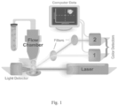
- Figure 1 shows a schematic view of a typical flow cytometer.
- the fluid is typically passed through a flow chamber, such as a small nozzle, generating a narrow fluid stream.
- a light beam such as a laser beam, illuminates the cells and particles and the like in the sample stream as they pass.
- Light detectors and color detectors 1 and 2 are positioned to detect scatter light and fluorescence light. This information is collected by a computer and then used by the flow cytometer to identify the particles or characteristics of the particles in the fluid.
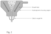
- Figure 2 shows a hydrodynamic focusing process of the flow chamber of the flow cytometer. When sheath fluid passes through the hydrodynamic focusing regions of the flow chamber, a single file of particles is produced in the flow cytometer system for analysis and characterization.
- the sheath fluid is often buffered saline or de-ionized (DI) water, but the sheath fluid may alternatively be any suitable fluid to hydrodynamically focus the sample fluid.
- DI de-ionized
- EP 2 743 673 A1 discloses background information.
- CN 107 782 657 A discloses background information.
- Embodiments of the subject invention provide systems and methods for connecting an external fluidic system to an existing flow-cytometer-based system (for example, as a hot-swap option) to expand the storage capability of the flow-cytometer-based system by making only minimal changes to the flow-cytometer-based system.
- a method for using a fluidic system is provided in claim 1.
- the fluidic system comprises a tubing connecting the fluidic system to a flow-cytometer-based system that has a first pump, a measurement device, a second pump, and a controller in operable communication with the second pump and the measurement device.
- the container contains a first fluid that is a sheath fluid flowing to the flow-cytometer-based system or a waste fluid flowing from the flow-cytometer-based system.
- the method comprises: operating, by the controller, the fluidic system to supply the first fluid from the container to the flow-cytometer-based system, when the first fluid is the sheath fluid, and to extract the first fluid from the flow-cytometer-based system and provide it to the container, when the first fluid is the waste fluid.
- system for particle charachterization or separation comprises a flow cytometer comprising a first pump; and a fluidic system in operable communication with the flow cytometer.
- the fluidic system comprises a container; a tubing connected to the flow cytometer; a second pump; a measurement device; and a controller in operable communication with the second pump and the measurement device, wherein the controller is configured to operate the fluidic system based on a condition of the flow cytometer.
- the measurement device measures a property of the sheath fluid or waste fluid in the container and transmits the measurement result to the controller.
- the controller determines whether the measurement result received is greater than or equal to a predetermined threshold value and adjusts an operation condition of the second pump to direct the fluid flow directions according to results of the determination.
- the fluidic system performs its functionalities independent from any signal communications with the flow-cytometer-based system. In alternative embodiments, the fluidic system performs its functionalities based on signal communications with the flow-cytometer-based system.
- Embodiments of the subject invention relate to advantageous external fluidic systems, methods of operating the same, and methods of using the same.
- An external fluidic system can be easily connected to an existing flow cytometer system to expand the fluid storage capability of the existing flow cytometer system by making only minimal changes to the existing flow cytometer system.
- an external fluidic system can be configured to, and/or used for, extracting waste fluid.
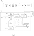
- an external waste fluidic system 200 for waste extraction includes an external waste pump 210 extracting the waste fluid from an (optional internal waste fluidic system 100 of the existing flow-cytometer-based system, and pumping the extracted waste fluid into a bulk container 220 connected to the external waste pump 210 via an optional valve 230 and can include a pressure sensor 250 coupled to the connecting tubing between the external waste pump 210 and the valve 230 to sense a pressure of the bulk container 220; a platform/load cell 225 coupled to the bulk container 220 for measuring a primary parameter such as a volume of the fluid contained by the bulk container 220; a float sensor 280 coupled to the bulk container 220 for measuring a secondary parameter such as a level of the fluid contained by the bulk container 220; and a power/control unit 260 coupled to the external waste pump 210, the pressure sensor 250, the float sensor 280, and the platform/load cell 225 to
- the external waste fluidic system 200 may include a vent filter 240 connected to the bulk container 220 to filter the vent of the bulk container 220 and a power source (not shown) connected to the external waste fluidic system 200 to supply power to the external waste fluidic system 200.
- the external waste fluidic system 200 includes connection tubing and optionally a coupler such as a dry break connector 270 to be connected to the existing flow-cytometer-based system.
- the existing flow-cytometer-based system that the external waste fluidic system 200 is capable of connecting to may include an internal waste fluidic system 100.
- the internal waste fluidic system 100 can include an internal waste evacuation pump 110 to extract the waste fluid from the internal waste bottle 120 that contains the waste fluid generated by the operations of the flow-cytometer-based system, and to pump the extracted waste fluid into an internal bulk waste tank 140.
- An internal waste valve 130 e.g., a waste valve that can control which internal waste tank the waste is directed to. such as the 1 ⁇ 2 valve in the Bio-Rad ZE5 system
- an internal waste three-way connector 150 are disposed between the internal waste evacuation pump 110 and the internal bulk waste tank 140.
- the external waste fluidic system 200 may be connected to the internal waste fluidic system 100 through the internal waste three-way connector 150.
- the bulk container 220 is used to contain the waste fluid generated by the flow-cytometer-based system and works as an extra storage in additional to the internal bulk waste tank 140 of the internal waste fluidic system 100, thereby enlarging the capacity of the flow-cytometer-based system for storage of the waste fluid when connecting the external waste fluidic system 200 to the flow-cytometer-based system.
- the bulk container 220 can be, for example, a vented tank with a volume of approximately 20 L, and the bulk container 220 may alternatively be any suitable container of any capacity.
- the external waste fluidic system 200 may be used to extract fluids other than the waste fluid.
- the external waste pump 210 may be used to extract a bleaching agent from a bleach container of the internal waste fluidic system 100 into the bulk container 220.
- the external waste pump 210 may extract a cleaning agent (such as a detergent or an antimicrobial) from a cleaning agent container of the flow-cytometer-based system into the bulk container 220.
- the external waste pump 210 can be a peristaltic pump or alternatively any other suitable type of pump.
- the external waste pump 210 can have a known flow rate to pump speed ratio such that a control of speeds of the external waste pump 210 corresponds to a control of the flow rate of the waste fluid.
- valve 230 connects the external waste pump 210 at one end and the bulk container 220 at the other end and functions to facilitate the control of the waste fluid flow.
- the optional valve 230 can be a check-valve, such as a spring loaded check valve, but may alternatively be any suitable valve such as a by-pass valve, a restrictive valve, and/or a shutoff valve.
- the platform/load cell 225 is a measurement device to measure a primary parameter of the waste fluid contained by the bulk container 220. Referring to Figure 3 , the platform/load cell 225 is preferably arranged such that it does not directly contact the waste fluid in the bulk container 220.
- the platform/load cell 225 includes one or more capacitive sensors disposed on or near the bulk container 220. The capacitive sensors can sense: (1) the discrete presence or absence of the bulk container 220; (2) the discrete presence or absence of the waste fluid in the bulk container 220; or (3) capacity of the waste fluid in the bulk container 220.
- the platform/load cell 225 may include one or more sensors to measure the weight, optical properties, acoustic properties or the like of the waste fluid and then calculate the volume of the waste fluid in the bulk container 220 based on the measurements.
- the float sensor 280 measures a secondary parameter. such as a level of the waste fluid contained by the bulk container 220, and is coupled to the power/control unit 260. If the platform/load cell 225 fails to function, the power/control unit 260 may determine that the bulk container 220 is full based a measurement of the level provided by the float sensor 280, in order to stop overflow of the bulk container 220. In other words, the float sensor 280 may operate as a backup sensor in addition to the main sensor of the platform/load cell 225 to inhibit or prevent the waste fluid, which may include biohazard (e.g., carboy), from overflowing from the bulk container 220.
- biohazard e.g., carboy
- the pressure sensor 250 shown in Figure 3 measures the pressure of the bulk container 220 and provides the measurement to the power/control unit 260, allowing the power/control unit 260 to detect whether the pressure of the bulk container 220 exceeds a predetermined threshold (e.g., reaches a high enough level that may lead to an explosion or other safety issues). If the pressure does exceed the predetermined threshold, operation of the external waste pump can be suspended or shut down.
- a predetermined threshold e.g., reaches a high enough level that may lead to an explosion or other safety issues.
- the power/control unit 260 of the external waste fluidic system 200 can be coupled to the external waste pump 210, the pressure sensor 250, the float sensor 280, and the platform/load cell 225.
- the power/control unit 260 sets or adjusts the pump speed of the external waste pump 210 so as to set or adjust the flow rate of the waste fluid from the flow-cytometer-based system into the external waste fluidic system 200.
- the power/control unit 260 may set or adjust operation parameters of the external waste pump 210 other than the pump speed, for example, power, pressure, or pump head and the like, for setting or adjusting the flow rate of the waste fluid from the flow-cytometer-based system to the external waste fluidic system 200.
- the power/control unit 260 can include a proportional-integral-derivative (PID) controller, but may alternatively be a proportional-integral (PI) controller, a proportional-derivative (PD) controller, a proportional (P) controller, or any other suitable type of controller.
- the power/control unit 260 may include an input device, including a keyboard, a mouse, a touch panel user interface, or other type of suitable input device, for receiving an input.
- the power/control unit 260 may include a display device including a display screen, a printer, or other type of suitable display device, for displaying output signals of the power/control unit 260 for a user to view.
- the user may send a command input such as a predetermined pump speed value to the power/control unit 260 through the input device.
- a command input such as a predetermined pump speed value
- the power/control unit 260 sets or adjusts the external waste pump 210 of the external waste fluidic system 200 to operate at the predetermined pump speed value requested by the user.
- the user may send a command input through the input device to the power/control unit 260 requesting that the power/control unit 260 automatically determines the optimal pump speed for the external waste pump 210 to operate, in order to achieve the goal of making the waste fluid of the flow-cytometer-based system to flow to the bulk container 220 of the external waste fluidic system 200 through the internal waste three-way connector 150.
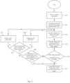
- Figure 4 is a flow diagram of an example process of configuring the external waste fluidic system 200 of Figure 3 to extract the waste fluid from the flow-cytometer-based system to the external waste fluidic system 200.
- the power/control unit 260 starts up the external waste fluidic system 200 including the external waste pump 210.
- the power/control unit 260 sets the external waste pump 210 to run at a pump speed higher than the pump speed of the internal waste evacuation pump 110 of the internal waste fluidic system 100 in response to an input from the user or alternatively, automatically determines an optimal pump speed for the external waste pump 210 to run at.
- the external waste pump 210 runs at the pump speed set at step S200. Because the pump speed of the external waste pump 210 is set to be higher than the pump speed of the internal waste evacuation pump 110. a pressure difference is created between the external waste fluidic system 200 and the internal waste fluidic system 100, causing the waste fluid of the flow-cytometer-based system to flow to the bulk container 220 of the external waste fluidic system 200.
- the external waste pump 210 and internal waste evacuation pump 110 can run simultaneously. at pump speeds in a same pump speed range of 0 - 100%.
- the power/control unit 260 may set or adjust the external waste pump 210 to be operated at a pump speed greater than 50% of the pump speed range.
- the platform/load cell 225 having one or more sensors senses or measures the volume of the waste fluid in the bulk container 220
- the float sensor 280 may measure the level of the waste fluid
- the pressure sensor 250 may measure the pressure of the bulk container 220.
- the measurement result or results of the volume, the level of waste fluid, and the pressure are transmitted to the power/control unit 260. In some cases, only one measurement (e.g.. the volume by the platform/load cell 225) may be taken and transmitted, if the measurement is outside a normal operating range.
- only two measurements may be taken and transmitted, if the either measurement is outside a normal operating range.
- the power/control unit 260 determines whether the volume of the waste fluid is greater than or equal to a predetermined threshold value. If it is determined that the volume measured is greater than or equal to the predetermined threshold value, to avoid an overflow at the bulk container 220, at step S600, the power/control unit 260 suspends or shuts down the operation of the external waste pump 210. As a result, there is no pump competing with the running internal waste evacuation pump 110. Consequently, the net suction between the external waste fluidic system 200 and the internal waste fluidic system 100 causes the waste fluid of the flow-cytometer-based system to flow only to the internal bulk waste tank 140 of the internal waste fluidic system 100, not to the external waste fluidic system 200.
- the power/control unit 260 determines whether the level of the waste fluid is greater than or equal to a predetermined threshold value of level or the pressure of the bulk container 220 is greater than or equal to a predetermined threshold value of pressure. If it is determined that the level measured is greater than or equal to the predetermined threshold value of level or the pressure measured is greater than or equal to the predetermined threshold value of pressure. to avoid an overflow at the bulk container 220 or occurrences of hazardous conditions in the bulk container 220. at step S600, the power/control unit 260 suspends or shuts down the operation of the external waste pump 210. In some cases, only one of these measurements may be taken; if the measurement exceeds the threshold value. operation may be ceased and it may not be necessary to take the other measurement at that time.
- step S510 it is determined that both the level measured is smaller than the predetermined threshold value of level and the pressure measured is smaller than the predetermined threshold value of pressure
- step S520 the difference between the volume measured and the predetermined threshold value of volume is calculated and the difference is compared with a predetermined delta value.
- step S540 if it is determined that the difference is greater than or equal to the predetermined delta value, the power/control unit 260 decreases the pump speed of the external waste pump 210 to reduce the inflow of the waste fluid to the external waste fluidic system 200 and at the same time, issues an alarm signal to the user in anticipation for an overflow at the bulk container 220.
- step 8560 the power/control unit 260 maintains the external waste pump 210 to run at the set pump speed until the measurement result is greater than or equal to a predetermined threshold value.
- the power/control unit 260 may, at step S560, maintain the external waste pump 210 to run at the set pump speed until the measurement result is greater than or equal to a predetermined threshold value.
- the external waste fluidic system 200 operates independent of any signal/input from the flow-cytometer-based system. In other words, there is no deliberate signal communication between the external waste fluidic system 200 and the flow-cytometer-based system.
- the external waste fluidic system 200 carries out its functionalities free of any signal communication with the flow-cytometer-based system.
- the external waste fluidic system 200 may be operated with signal communications with the flow-cytometer-based system.
- the external waste fluidic system 200 carries out its functionalities in response to an input or request signal from the existing flow-cytometer-based system and by transmitting an output or feedback signal to the existing flow-cytometer-based system.
- FIG. 5 is a schematic view of an external sheath fluidic system connected to an (optional) internal sheath fluidic system of a flow-cytometer-based system according to an embodiment of the subject invention.
- an external sheath fluidic system 500 for supplying sheath fluid includes an external sheath pump 510 supplying the sheath fluid to the (optional) internal sheath fluidic system 400 of the existing flow-cytometer-based system, and pumping the sheath fluid from a bulk container 520 connected to the external sheath pump 510 via an optional valve 530 and can include a pressure sensor 550 coupled to the connecting tubing between the external sheath pump 510 and the valve 530 to sense pressures of the external sheath pump 510; a platform/load cell 525 coupled to the bulk container 520 for measuring parameters of the fluid contained by the bulk container 520; and a power/control unit 560 coupled to the external sheath pump 510, the pressure sensor 550, and the platform/load cell 525 to implement control functionalities
- the external sheath fluidic system 500 includes a pressure regulator (not shown) or a power source (not shown) connected to the external sheath fluidic system 500 to supply power to the external sheath fluidic system 500.
- the external sheath fluidic system 500 of Figure 5 includes connection tubing optionally a coupler such as a dry break connector 570 to be connected to the existing flow-cytometer-based system.
- the existing flow-cytometer-based system that the external sheath fluidic system 500 is capable of connecting to may include an internal sheath fluidic system 400.
- the internal sheath fluidic system 400 is optional, though the internal bulk sheath tank 440 will generally be present in most cases. If present, the internal sheath fluidic system 400 includes an internal sheath pump 410 to supply the sheath fluid to the internal sheath bottle 420 from the internal bulk sheath tank 440.
- An internal sheath valve 430 (e.g...
- a sheath valve that can control which internal sheath tank the sheath is directed to such as the 1 ⁇ 2 valve in the Bio-Rad ZES system
- an internal sheath three-way connector 450, and an external source valve 455 can be disposed between the internal sheath pump 410 and the internal bulk sheath tank 440.
- the external sheath fluidic system 500 may be connected to the internal sheath fluidic system 400 through the internal sheath three-way connector 450 and the external source valve 455.
- the external source valve 455 may be configured to allow the internal bulk sheath tank 440 to be filled from the bulk container 520; and when the level of the sheath fluid in the internal bulk sheath tank 440 reaches a certain predetermined level (e.g., 75% full), the external source valve 455 may be configured to close in order to stop filling the internal bulk sheath tank 440 from the bulk container 520.
- a predetermined level for example, less than half full
- the bulk container 520 may be used to contain the sheath fluid supplied to the flow-cytometer-based system and works as an extra storage in additional to the internal bulk sheath tank 440 of the internal sheath fluidic system 400, thereby enlarging the capacity of the flow-cytometer-based system for storage of the sheath fluid when connecting the external sheath fluidic system 500 to the flow-cytometer-based system.
- the bulk container 520 can be, for example, a tank with a volume of approximately 20 L, and the bulk container 520 may alternatively be any suitable container of any capacity.
- the external sheath fluidic system 500 may be used to supply fluids other than the sheath fluid.
- the external sheath pump 510 may be used to supply a bleaching agent to a bleach container of the internal sheath fluidic system 400 from the bulk container 520.
- the external sheath pump 510 may supply a cleaning agent (such as a detergent or an antimicrobial) to a cleaning agent container of the flow-cytometer-based system from the bulk container 520.
- the external sheath pump 510 can be a peristaltic pump or alternatively any other suitable type of pump.
- the external sheath pump 510 can have a known flow rate to pump speed ratio such that a control of speeds of the external sheath pump 510 corresponds to a control of the flow rate of the sheath fluid.
- the valve 530 connects the external sheath pump 510 at one end and the bulk container 520 at the other end and functions to facilitate the control of the sheath fluid flow.
- the optional valve 530 can be a check-valve, such as a spring loaded check valve, but may alternatively be any suitable valve such as a by-pass valve, a restrictive valve, and/or a shutoff valve.
- the platform/load cell 525 is a measurement device to measure parameters of the sheath fluid contained by the bulk container 520.
- the platform/load cell 525 can be arranged such that is does not directly contact the sheath fluid in the bulk container 520.
- the platform/load cell 525 includes one or more capacitive sensors disposed on or near the bulk container 520. The capacitive sensors can sense: (1) the discrete presence or absence of the bulk container 520, (2) the discrete presence or absence of the sheath fluid in the bulk container 520; or (3) capacity or a level of the sheath fluid in the bulk container 520.
- the platform/load cell 525 may include one or more sensors to measure the weight, optical properties, acoustic properties or the like of the sheath fluid and then calculate the volume or level of the sheath fluid in the bulk container 520 based on the measurement.
- the power/control unit 560 of the external sheath fluidic system 500 can be coupled to the external sheath pump 510, the pressure sensor 550, and the platform/load cell 525.
- the power/control unit 560 sets or adjusts the pump speed of the external sheath pump 510 so as to set or adjust the flow rate of the sheath fluid supplied to the flow-cytometer-based system from the external sheath fluidic system 500.
- the power/control unit 560 may set or adjust operation parameters of the external sheath pump 510 other than the pump speed, for example, power, pressure, or pump head and the like, for setting or adjusting the flow rate of the sheath fluid supplied to the flow-cytometer-based system from external waste fluidic system 500.
- the power/control unit 560 can include a proportional-integral-derivative (PID) controller, but may alternatively be a proportional-integral (PI) controller, a proportional-derivative (PD) controller, a proportional (P) controller, or any other suitable type of controller.
- the power/control unit 560 may include an input device, including a keyboard, a mouse, a touch panel user interface, or other type of suitable input device, for receiving an input.
- the power/control unit 560 may include a display device including a display screen, a printer, or other type of suitable display device, for displaying output signals of the power/control unit 560 for a user to view.
- the user may send a command input such as a predetermined pump speed value to the power/control unit 560 through the input device.
- a command input such as a predetermined pump speed value
- the power/control unit 560 sets or adjusts the external sheath pump 510 of the external sheath fluidic system 500 to operate at predetermined pump speed value requested by the user.
- the user may send a command input through the input device to the power/control unit 560 requesting that the power/control unit 560 automatically determines the optimal pump speed for the external sheath pump 510 to operate at, in order to achieve the goal of supplying the sheath fluid to the flow-cytometer-based system from the bulk container 520 of the external sheath fluidic system 500 through the internal sheath three-way connector 450.
- the internal sheath pump 410 keeps running to supply the sheath fluid from the internal bulk sheath tank 440 to the internal sheath bottle 420.
- a level of the sheath fluid in the internal bulk sheath tank 440 drops below a first predetermined level (for example, 50% full)
- the external source valve 455 is configured to open, causing the external sheath fluidic system 500 shown in Figure 5 to supply the sheath fluid from the bulk container 520 to the flow-cytometer-based system.
- FIG. 6 is a flow diagram of an example process of configuring the external sheath fluidic system 500 to supply the sheath fluid to the flow-cytometer-based system.
- step S700 when the power/control unit 560 senses that the external source valve 455 is open causing the pressure of the external sheath fluidic system 500 to change, the power/control unit 560 starts up the external sheath pump 510.
- the power/control unit 560 sets the external sheath pump 510 to run at a pump speed to generate a pressure of the external sheath fluidic system 500 that is sufficiently higher than a pressure of the internal sheath fluidic system 400 in response to an input or, alternatively, automatically determines an optimal pump speed for the external sheath pump 510 to run at.
- the external sheath pump 510 runs at the pump speed set at step S800.
- the sheath fluid contained in the bulk container 520 is pumped to the internal bulk sheath tank 440 due to the sufficient high pressure difference between the external sheath fluidic system 500 and the internal sheath fluidic system 400.
- the platform/load cell 525 having one or more sensors senses or measures the volume of the sheath fluid in the bulk container 520 and the pressure sensor 550 senses or measures the pressure of the external sheath fluidic system 500.
- the measurement results of the volume and the pressure are transmitted to the power/control unit 560.
- the power/control unit 560 determines whether the volume measured is smaller than a predetermined threshold value of volume. If it is determined that the volume measured is smaller than the predetermined threshold value for the volume, to avoid pumping from an empty bulk container 520, at step S1200, the power/control unit 560 suspends or shuts down the operation of the external sheath pump 510.
- the flow-cytometer-based system continues to operate with the internal sheath fluidic system 400 causing the sheath fluid to be supplied only from the internal bulk sheath tank 440 of the internal sheath fluidic system 400, not from the external sheath fluidic system 500. If, at step S1100, it is determined that the volume measured is greater than or equal to the predetermined threshold value for the volume, then, at step S1150, the power/control unit 560 determines whether the pressure measured is greater than a predetermined threshold value for the pressure.
- the external source valve 455 is configured to close.
- step S1150 when the power/control unit 560 senses that the external source valve 455 is closed causing the pressure of the external sheath fluidic system 500 to go up to a level greater than the predetermined threshold value for the pressure, to avoid occurrences of pump running dead with leakage conditions in the external sheath fluidic system 500, at step S1160, the power/control unit 560 suspends the operation of the external sheath pump 510 and only turns the external sheath pump 510 back on when the pressure measured is determined to be smaller than or equal to the predetermined threshold value for the pressure. On the other hand, if, at step S1150, it is determined that the pressure measured is smaller than or equal to the predetermined threshold value for the pressure, then the power/control unit 560 maintains the external sheath pump 510 to run at the set pump speed.
- Such processes of filling the internal bulk sheath tank 440 with the sheath fluid from the bulk container 520 by starting and suspending the external sheath pump 510 repeat until a volume of the sheath fluid in the bulk container 520 is smaller than the predetermined threshold value for the volume (for example, until the bulk container 520 becomes empty).
- the external sheath fluidic system 500 operates independent of any signal/input from the flow-cytometer-based system. In other words. there is no deliberate signal communication between the external sheath fluidic system 500 and the flow-cytometer-based system.
- the external sheath fluidic system 500 carries out its functionalities free of any signal communication with the flow-cytometer-based system.
- the external sheath fluidic system 500 may be operated with signal communications with the flow-cytometer-based system.
- the external sheath fluidic system 500 carries out its functionalities in response to an input or request signal from the existing flow-cytometer-based system and by transmitting an output or feedback signal to the existing flow-cytometer-based system.
- different color caps can be used on the various components to help easily distinguish different containers (e.g., bulk container, internal bulk sheath tank, etc.) from each other and/or different valves or pumps from each other
- Figure 7 provides illustrations of a user interface of a control panel (for example, an electro-mechanical control switch) of certain embodiments of the subject invention. It should be understood that the user interface shown in Figure 7 is merely for illustrative purposes and should not be construed as intending to limit how and in what manner the external fluidic system or the flow-cytometer-based system carries out its functionalities.
- a control panel for example, an electro-mechanical control switch
- the user interface of the control panel includes a System On/Off button to switch the external waste pump or the external sheath pump on or off; a System Running LED indicating the status of the above mentioned pumps wherein when the System Running LED is on, it indicates that the pumps are on and running; and a System Stopped LED indicating the status of the pumps wherein when the System Stopped LED is on, it indicates that the pumps are stopped.
- the user interface of the control panel includes a Silence Alarm button, which when pressed and then immediately released, causes an alarm signaling a hazardous condition (for example, the bulk container is full of waste fluid) of the external fluidic system to be silenced.
- the volume of the alarm sound can be adjusted. For example, when the Silence Alarm button is pressed and held for more than 5 seconds, the volume of the alarm sound can increase until the maximum volume is reached. If the Silence Alarm button is pressed and held for more than 5 seconds after the maximum volume is reached, the sound of the alarm can be silenced or the volume can decrease gradually until it is silenced. Distinguishable color caps can be used for the buttons of the user interface of the control panel to distinguish different functionalities of these buttons.
- the user interface of the control panel further includes a Full LED indicator (for example, it can be green for the external sheath fluidic system and turn red and flashing for the external waste fluidic system when the bulk container for containing waste fluid is full).
- An Empty LED is included (for example, it can be green for the external waste fluidic system and turn red and flashing for the external sheath fluidic system when the bulk container for containing the sheath fluid is empty.
- a group of Level LEDs are also included indicating different levels (for example, 1 ⁇ 4 full, 1 ⁇ 2 full, or 3 ⁇ 4 full) of the fluid contained in the bulk container.
- the user interface of the control panel can include one or more hidden buttons that are not labeled or otherwise marked and are intended to be exclusively accessible to authorized personnel for service use.
- One of the hidden buttons can be an empty calibration button for calibration of an empty bulk container at service time. For example, when the empty calibration button is pressed and held for more than 5 seconds, values of certain parameters of the empty bulk container will be stored in a storage device such as a flash memory of a controller board (for example, a microcontroller or an FPGA controller).
- the other hidden button can be a full calibration button for calibration of a full bulk container. For example, when the full calibration button is pressed and held for more than 5 seconds, values of certain parameters of the full bulk container can be stored in a storage device such as a flash memory of a controller board (for example, a microcontroller or an FPGA controller).
- the methods and processes described herein can be embodied as code and/or data.
- the software code and data described herein can be stored on one or more machine-readable media (e.g., computer-readable media), which may include any device or medium that can store code and/or data for use by a computer system.
- machine-readable media e.g., computer-readable media
- the computer system and/or processor When a computer system and/or processor reads and executes the code and/or data stored on a computer-readable medium, the computer system and/or processor performs the methods and processes embodied as data structures and code stored within the computer-readable storage medium.
- computer-readable media include removable and non-removable structures/devices that can be used for storage of information, such as computer-readable instructions, data structures, program modules, and other data used by a computing system/environment.
- a computer-readable medium includes, but is not limited to, volatile memory such as random access memories (RAM, DRAM, SRAM); and non-volatile memory such as flash memory, various read-only-memories (ROM, PROM, EPROM, EEPROM), magnetic and ferromagnetic/ferroelectric memories (MRAM, FeRAM), and magnetic and optical storage devices (hard drives, magnetic tape, CDs, DVDs); network devices; or other media now known or later developed that are capable of storing computer-readable information/data.
- volatile memory such as random access memories (RAM, DRAM, SRAM
- non-volatile memory such as flash memory, various read-only-memories (ROM, PROM, EPROM, EEPROM), magnetic and ferromagnetic/ferroelectric memories (MRAM, FeRAM), and magnetic and optical
- Computer-readable media should not be construed or interpreted to include any propagating signals.
- a computer-readable medium can be, for example, a compact disc (CD), digital video disc (DVD), flash memory device, volatile memory, or a hard disk drive (HDD), such as an external HDD or the HDD of a computing device, though embodiments are not limited thereto.
- a computing device can be, for example, a laptop computer, desktop computer, server, cell phone, or tablet, though embodiments are not limited thereto.
- the external fluidic system can include one or more sheath fluid containers, one or more waste fluid containers, or a combination of any number of waste fluid containers and sheath fluid containers.
- the external fluidic system can include additional control functions including, but not limited to:
- the external fluidic system may further include a mass storage device capable of storing and accessing software instructions and/or data to carry out the above mentioned certain methods and processes.
- a mass storage device capable of storing and accessing software instructions and/or data to carry out the above mentioned certain methods and processes.
- the above mentioned methods and processes can be carried out by hardware implementations including but are not limited to, application-specific integrated circuit (ASIC) chips, field programmable gate arrays (FPGAs), and other programmable logic devices now known or later developed.
- ASIC application-specific integrated circuit
- FPGAs field programmable gate arrays
- the external fluidic system as illustrated by the embodiments of subject invention When the external fluidic system as illustrated by the embodiments of subject invention is connected to an existing flow-cytometer-based system, the overall capacity of the waste storage or the sheath storage of the existing flow-cytometer-based system can be easily expanded beyond its designed maximum capacity. Moreover, the external fluidic system can be hot plugged into or hot unplugged from the existing flow-cytometer-based system that runs an analysis of samples. Because the external fluidic system may operate without receiving a deliberate signal from or transmitting a deliberate signal to the existing flow-cytometer-based system, none of the components, structures, connections, control procedures, software program/data of the existing flow-cytometer-based system needs to be altered or reconfigured.
- the external fluidic system can be connected to a running flow-cytometer-based system as a hot swap connection option without interruptions to the operations of the flow-cytometer-based system. Further, because the external fluidic system is a self-contained system capable of being connected to an existing flow-cytometer-based system, it requires minimal efforts for maintainance and service, making it very suitable for commercial applications.
Landscapes
- Chemical & Material Sciences (AREA)
- General Health & Medical Sciences (AREA)
- Life Sciences & Earth Sciences (AREA)
- Health & Medical Sciences (AREA)
- Analytical Chemistry (AREA)
- Biochemistry (AREA)
- Physics & Mathematics (AREA)
- General Physics & Mathematics (AREA)
- Immunology (AREA)
- Pathology (AREA)
- Dispersion Chemistry (AREA)
- Apparatus Associated With Microorganisms And Enzymes (AREA)
- External Artificial Organs (AREA)
Description
- This application claims priority to
U.S. Patent Application Serial No. 16/214,674, filed December 10, 2018 - Flow cytometers are useful for analyzing sample fluids having cells or particles and identifying characteristics of the cells or particles contained within a fluid. These cells or particles may be biological or physical samples that are collected for analysis and/or separation. The sample is mixed with a sheath fluid for transporting the cells or particles through the flow cytometer. The particles may comprise biological cells, calibration beads, physical sample particles, or other particles of interest.
-
Figure 1 shows a schematic view of a typical flow cytometer. Referring toFigure 1 , the fluid is typically passed through a flow chamber, such as a small nozzle, generating a narrow fluid stream. A light beam, such as a laser beam, illuminates the cells and particles and the like in the sample stream as they pass. Light detectors and color detectors 1 and 2 are positioned to detect scatter light and fluorescence light. This information is collected by a computer and then used by the flow cytometer to identify the particles or characteristics of the particles in the fluid.Figure 2 shows a hydrodynamic focusing process of the flow chamber of the flow cytometer. When sheath fluid passes through the hydrodynamic focusing regions of the flow chamber, a single file of particles is produced in the flow cytometer system for analysis and characterization. The sheath fluid is often buffered saline or de-ionized (DI) water, but the sheath fluid may alternatively be any suitable fluid to hydrodynamically focus the sample fluid. - As flow cytometer systems become smaller and more portable, the sheath fluid containers and the waste fluid containers are becoming correspondingly smaller and more portable. As a result, portable flow cytometer systems may exhaust the supply of sheath fluid or overfill the waste container during the course of an experiment. While refilling or replacing the sheath fluid container and emptying the waste container takes a nominal amount of time and effort, the user must continuously suspend the experiment to ensure that the sheath fluid is not entirely depleted and that the waste container is not overfilled. Should the sheath container become empty, data sampled from or around the time when the sheath fluid ran out may be compromised. Accordingly, a user will typically have to provide a new sample material and run new experiments to ensure the accuracy of the data. Similarly, should the waste container overflow, the user will undoubtedly have to suspend the experiment in order to clean and sterilize the area. As the samples analyzed by flow cytometers vary from relatively benign to much less so, the overflow of the waste container can cause serious delays and perhaps hazardous conditions.
-
EP 2 743 673 A1 discloses background information. -
CN 107 782 657 A discloses background information. -
US 2009/262356 A1 discloses background information. - In view of the problems in the related art, there is a need for an improved flow cytometer system that is adapted to determine a volume of the sheath fluid or the waste fluid during operations and can expand the storage capacity of the sheath fluid or the waste fluid without causing any interruptions to the normal operations of a running flow cytometer system.
- Aspects of the invention are set out in the appended independent claims.
- Embodiments of the subject invention provide systems and methods for connecting an external fluidic system to an existing flow-cytometer-based system (for example, as a hot-swap option) to expand the storage capability of the flow-cytometer-based system by making only minimal changes to the flow-cytometer-based system.
- In an aspect of the invention, a method for using a fluidic system is provided in claim 1.
- The fluidic system comprises a tubing connecting the fluidic system to a flow-cytometer-based system that has a first pump, a measurement device, a second pump, and a controller in operable communication with the second pump and the measurement device. The container contains a first fluid that is a sheath fluid flowing to the flow-cytometer-based system or a waste fluid flowing from the flow-cytometer-based system. The method comprises: operating, by the controller, the fluidic system to supply the first fluid from the container to the flow-cytometer-based system, when the first fluid is the sheath fluid, and to extract the first fluid from the flow-cytometer-based system and provide it to the container, when the first fluid is the waste fluid.
- In another aspect of the invention, system for particle charachterization or separation is provided in claim 6. The system for particle characterization or separation comprises a flow cytometer comprising a first pump; and a fluidic system in operable communication with the flow cytometer. The fluidic system comprises a container; a tubing connected to the flow cytometer; a second pump; a measurement device; and a controller in operable communication with the second pump and the measurement device, wherein the controller is configured to operate the fluidic system based on a condition of the flow cytometer.
- In some embodiments, the measurement device measures a property of the sheath fluid or waste fluid in the container and transmits the measurement result to the controller. The controller determines whether the measurement result received is greater than or equal to a predetermined threshold value and adjusts an operation condition of the second pump to direct the fluid flow directions according to results of the determination.
- In certain embodiments, the fluidic system performs its functionalities independent from any signal communications with the flow-cytometer-based system. In alternative embodiments, the fluidic system performs its functionalities based on signal communications with the flow-cytometer-based system.
-
-
Figure 1 is a schematic representation of a prior art flow cytometer system. -
Figure 2 is a schematic representation of a hydrodynamic focusing process that produces a single stream of cells/particles in a prior art flow cytometer system. -
Figure 3 is a schematic view of an external waste fluidic system connected to an internal waste fluidic system of a flow-cytometer-based system according to an embodiment of the subject invention. -
Figure 4 is a flow diagram illustrating operations of the waste fluidic system illustrated inFigure 3 according to an embodiment of the subject invention. -
Figure 5 is a schematic view of an external sheath fluidic system connected to an internal sheath fluidic system of a flow-cytometer-based system according to an embodiment of the subject invention. -
Figure 6 is a flow diagram illustrating operations of the sheath fluidic system illustrated inFigure 5 according to an embodiment of the subject invention. -
Figure 7 is a schematic representation of a user interface of a control panel according to an embodiment of the subject invention. - Embodiments of the subject invention relate to advantageous external fluidic systems, methods of operating the same, and methods of using the same. An external fluidic system can be easily connected to an existing flow cytometer system to expand the fluid storage capability of the existing flow cytometer system by making only minimal changes to the existing flow cytometer system.
- In some embodiments, an external fluidic system can be configured to, and/or used for, extracting waste fluid. Referring to
Figure 3 , an external wastefluidic system 200 for waste extraction includes anexternal waste pump 210 extracting the waste fluid from an (optional internal wastefluidic system 100 of the existing flow-cytometer-based system, and pumping the extracted waste fluid into abulk container 220 connected to theexternal waste pump 210 via anoptional valve 230 and can include apressure sensor 250 coupled to the connecting tubing between theexternal waste pump 210 and thevalve 230 to sense a pressure of thebulk container 220; a platform/load cell 225 coupled to thebulk container 220 for measuring a primary parameter such as a volume of the fluid contained by thebulk container 220; afloat sensor 280 coupled to thebulk container 220 for measuring a secondary parameter such as a level of the fluid contained by thebulk container 220; and a power/control unit 260 coupled to theexternal waste pump 210, thepressure sensor 250, thefloat sensor 280, and the platform/load cell 225 to implement control functionalities of the external wastefluidic system 200. The external wastefluidic system 200 may include avent filter 240 connected to thebulk container 220 to filter the vent of thebulk container 220 and a power source (not shown) connected to the external wastefluidic system 200 to supply power to the external wastefluidic system 200. The external wastefluidic system 200 includes connection tubing and optionally a coupler such as adry break connector 270 to be connected to the existing flow-cytometer-based system. - The existing flow-cytometer-based system that the external waste
fluidic system 200 is capable of connecting to may include an internal wastefluidic system 100. The internal wastefluidic system 100, if present, can include an internalwaste evacuation pump 110 to extract the waste fluid from theinternal waste bottle 120 that contains the waste fluid generated by the operations of the flow-cytometer-based system, and to pump the extracted waste fluid into an internalbulk waste tank 140. An internal waste valve 130 (e.g., a waste valve that can control which internal waste tank the waste is directed to. such as the ½ valve in the Bio-Rad ZE5 system) and an internal waste three-way connector 150 are disposed between the internalwaste evacuation pump 110 and the internalbulk waste tank 140. The external wastefluidic system 200 may be connected to the internal wastefluidic system 100 through the internal waste three-way connector 150. - The
bulk container 220 is used to contain the waste fluid generated by the flow-cytometer-based system and works as an extra storage in additional to the internalbulk waste tank 140 of the internal wastefluidic system 100, thereby enlarging the capacity of the flow-cytometer-based system for storage of the waste fluid when connecting the external wastefluidic system 200 to the flow-cytometer-based system. Thebulk container 220 can be, for example, a vented tank with a volume of approximately 20 L, and thebulk container 220 may alternatively be any suitable container of any capacity. - In addition, the external waste
fluidic system 200 may be used to extract fluids other than the waste fluid. For example, after the analysis operations of the flow-cytometer-based system are complete, theexternal waste pump 210 may be used to extract a bleaching agent from a bleach container of the internal wastefluidic system 100 into thebulk container 220. As another example, after the analysis operations of the flow-cytometer-based system are complete, theexternal waste pump 210 may extract a cleaning agent (such as a detergent or an antimicrobial) from a cleaning agent container of the flow-cytometer-based system into thebulk container 220. - The
external waste pump 210 can be a peristaltic pump or alternatively any other suitable type of pump. Theexternal waste pump 210 can have a known flow rate to pump speed ratio such that a control of speeds of theexternal waste pump 210 corresponds to a control of the flow rate of the waste fluid. - Referring again to
Figure 3 , thevalve 230 connects theexternal waste pump 210 at one end and thebulk container 220 at the other end and functions to facilitate the control of the waste fluid flow. Theoptional valve 230 can be a check-valve, such as a spring loaded check valve, but may alternatively be any suitable valve such as a by-pass valve, a restrictive valve, and/or a shutoff valve. - The platform/
load cell 225 is a measurement device to measure a primary parameter of the waste fluid contained by thebulk container 220. Referring toFigure 3 , the platform/load cell 225 is preferably arranged such that it does not directly contact the waste fluid in thebulk container 220. In an embodiment, the platform/load cell 225 includes one or more capacitive sensors disposed on or near thebulk container 220. The capacitive sensors can sense: (1) the discrete presence or absence of thebulk container 220; (2) the discrete presence or absence of the waste fluid in thebulk container 220; or (3) capacity of the waste fluid in thebulk container 220. Alternatively, the platform/load cell 225 may include one or more sensors to measure the weight, optical properties, acoustic properties or the like of the waste fluid and then calculate the volume of the waste fluid in thebulk container 220 based on the measurements. - As illustrated by
Figure 3 , thefloat sensor 280 measures a secondary parameter. such as a level of the waste fluid contained by thebulk container 220, and is coupled to the power/control unit 260. If the platform/load cell 225 fails to function, the power/control unit 260 may determine that thebulk container 220 is full based a measurement of the level provided by thefloat sensor 280, in order to stop overflow of thebulk container 220. In other words, thefloat sensor 280 may operate as a backup sensor in addition to the main sensor of the platform/load cell 225 to inhibit or prevent the waste fluid, which may include biohazard (e.g., carboy), from overflowing from thebulk container 220. Thepressure sensor 250 shown inFigure 3 measures the pressure of thebulk container 220 and provides the measurement to the power/control unit 260, allowing the power/control unit 260 to detect whether the pressure of thebulk container 220 exceeds a predetermined threshold (e.g., reaches a high enough level that may lead to an explosion or other safety issues). If the pressure does exceed the predetermined threshold, operation of the external waste pump can be suspended or shut down. - The power/
control unit 260 of the externalwaste fluidic system 200 can be coupled to theexternal waste pump 210, thepressure sensor 250, thefloat sensor 280, and the platform/load cell 225. In an embodiment, the power/control unit 260 sets or adjusts the pump speed of theexternal waste pump 210 so as to set or adjust the flow rate of the waste fluid from the flow-cytometer-based system into the externalwaste fluidic system 200. Alternatively, the power/control unit 260 may set or adjust operation parameters of theexternal waste pump 210 other than the pump speed, for example, power, pressure, or pump head and the like, for setting or adjusting the flow rate of the waste fluid from the flow-cytometer-based system to the externalwaste fluidic system 200. - The power/
control unit 260 can include a proportional-integral-derivative (PID) controller, but may alternatively be a proportional-integral (PI) controller, a proportional-derivative (PD) controller, a proportional (P) controller, or any other suitable type of controller. The power/control unit 260 may include an input device, including a keyboard, a mouse, a touch panel user interface, or other type of suitable input device, for receiving an input. In addition, the power/control unit 260 may include a display device including a display screen, a printer, or other type of suitable display device, for displaying output signals of the power/control unit 260 for a user to view. Therefore, the user may send a command input such as a predetermined pump speed value to the power/control unit 260 through the input device. When receiving the command input from the user, the power/control unit 260 sets or adjusts theexternal waste pump 210 of the externalwaste fluidic system 200 to operate at the predetermined pump speed value requested by the user. - In another embodiment, the user may send a command input through the input device to the power/
control unit 260 requesting that the power/control unit 260 automatically determines the optimal pump speed for theexternal waste pump 210 to operate, in order to achieve the goal of making the waste fluid of the flow-cytometer-based system to flow to thebulk container 220 of the externalwaste fluidic system 200 through the internal waste three-way connector 150. -
Figure 4 is a flow diagram of an example process of configuring the externalwaste fluidic system 200 ofFigure 3 to extract the waste fluid from the flow-cytometer-based system to the externalwaste fluidic system 200. Referring toFigure 4 , at step S100, when the flow-cytometer-based system is operated in a normal condition analyzing samples. the power/control unit 260 starts up the externalwaste fluidic system 200 including theexternal waste pump 210. - Next, at step S200, the power/
control unit 260 sets theexternal waste pump 210 to run at a pump speed higher than the pump speed of the internalwaste evacuation pump 110 of the internalwaste fluidic system 100 in response to an input from the user or alternatively, automatically determines an optimal pump speed for theexternal waste pump 210 to run at. - Next, at step S300, the
external waste pump 210 runs at the pump speed set at step S200. Because the pump speed of theexternal waste pump 210 is set to be higher than the pump speed of the internalwaste evacuation pump 110. a pressure difference is created between the externalwaste fluidic system 200 and the internalwaste fluidic system 100, causing the waste fluid of the flow-cytometer-based system to flow to thebulk container 220 of the externalwaste fluidic system 200. - For example, the
external waste pump 210 and internalwaste evacuation pump 110 can run simultaneously. at pump speeds in a same pump speed range of 0 - 100%. When the internalwaste evacuation pump 110 runs at 20% of the pump speed range during a normal operation condition of the flow-cytometer-based system and runs at 50% of the pump speed range in certain special operation conditions, the power/control unit 260 may set or adjust theexternal waste pump 210 to be operated at a pump speed greater than 50% of the pump speed range. - Because the internal
waste evacuation pump 110 and theexternal waste pump 210 run in parallel and compete with each other, when theexternal waste pump 210 runs at a pump speed higher than the internalwaste evacuation pump 110, a net suction is generated and applied to the tubing leading to the internalbulk waste tank 140, thereby drawing the waste fluid generated by the flow-cytometer-based system to flow to thebulk container 220 of the externalwaste fluidic system 200 through the internal waste three-way connector 150 of the internalwaste fluidic system 100. - Next, at step S400, the platform/
load cell 225 having one or more sensors senses or measures the volume of the waste fluid in thebulk container 220, thefloat sensor 280 may measure the level of the waste fluid, and thepressure sensor 250 may measure the pressure of thebulk container 220. The measurement result or results of the volume, the level of waste fluid, and the pressure are transmitted to the power/control unit 260. In some cases, only one measurement (e.g.. the volume by the platform/load cell 225) may be taken and transmitted, if the measurement is outside a normal operating range. In some cases, only two measurements (e.g., the volume by the platform/load cell 225 and either one of the level of the waste fluid by thefloat sensor 280 or the pressure of the bulk container by the pressure sensor 250) may be taken and transmitted, if the either measurement is outside a normal operating range. - Next, at step S500, when receiving the measurement results, the power/
control unit 260 determines whether the volume of the waste fluid is greater than or equal to a predetermined threshold value. If it is determined that the volume measured is greater than or equal to the predetermined threshold value, to avoid an overflow at thebulk container 220, at step S600, the power/control unit 260 suspends or shuts down the operation of theexternal waste pump 210. As a result, there is no pump competing with the running internalwaste evacuation pump 110. Consequently, the net suction between the externalwaste fluidic system 200 and the internalwaste fluidic system 100 causes the waste fluid of the flow-cytometer-based system to flow only to the internalbulk waste tank 140 of the internalwaste fluidic system 100, not to the externalwaste fluidic system 200. - If, at step S500, it is determined that the volume measured is smaller than the predetermined threshold value, then at step S510, the power/
control unit 260 determines whether the level of the waste fluid is greater than or equal to a predetermined threshold value of level or the pressure of thebulk container 220 is greater than or equal to a predetermined threshold value of pressure. If it is determined that the level measured is greater than or equal to the predetermined threshold value of level or the pressure measured is greater than or equal to the predetermined threshold value of pressure. to avoid an overflow at thebulk container 220 or occurrences of hazardous conditions in thebulk container 220. at step S600, the power/control unit 260 suspends or shuts down the operation of theexternal waste pump 210. In some cases, only one of these measurements may be taken; if the measurement exceeds the threshold value. operation may be ceased and it may not be necessary to take the other measurement at that time. - On the other hand, if, at the step S510, it is determined that both the level measured is smaller than the predetermined threshold value of level and the pressure measured is smaller than the predetermined threshold value of pressure, then at optional step S520, the difference between the volume measured and the predetermined threshold value of volume is calculated and the difference is compared with a predetermined delta value. At optional step S540, if it is determined that the difference is greater than or equal to the predetermined delta value, the power/
control unit 260 decreases the pump speed of theexternal waste pump 210 to reduce the inflow of the waste fluid to the externalwaste fluidic system 200 and at the same time, issues an alarm signal to the user in anticipation for an overflow at thebulk container 220. If at optional step S520. it is determined that the difference is smaller than the predetermined delta value, then at step 8560, the power/control unit 260 maintains theexternal waste pump 210 to run at the set pump speed until the measurement result is greater than or equal to a predetermined threshold value. - Alternatively, at the step S510, if it is determined that the level measured is smaller than the predetermined threshold value of level and the pressure measured is smaller than the predetermined threshold value of pressure, and if the optional steps S520 and S540 are not performed, the power/
control unit 260 may, at step S560, maintain theexternal waste pump 210 to run at the set pump speed until the measurement result is greater than or equal to a predetermined threshold value. In an embodiment, the externalwaste fluidic system 200 operates independent of any signal/input from the flow-cytometer-based system. In other words, there is no deliberate signal communication between the externalwaste fluidic system 200 and the flow-cytometer-based system. Even though the systems are connected and in operable communication or operation via at least the tubing (or other connection means), there is no deliberate sending or receiving of signals between the systems (e.g.. electric/electronic signals. magnetic signals, optical signals, pressure signals, pneumatic signals, or strain signals). Therefore, the externalwaste fluidic system 200 carries out its functionalities free of any signal communication with the flow-cytometer-based system. - In another embodiment, the external
waste fluidic system 200 may be operated with signal communications with the flow-cytometer-based system. In other words, the externalwaste fluidic system 200 carries out its functionalities in response to an input or request signal from the existing flow-cytometer-based system and by transmitting an output or feedback signal to the existing flow-cytometer-based system. -
Figure 5 is a schematic view of an external sheath fluidic system connected to an (optional) internal sheath fluidic system of a flow-cytometer-based system according to an embodiment of the subject invention. Referring toFigure 5 , an externalsheath fluidic system 500 for supplying sheath fluid includes anexternal sheath pump 510 supplying the sheath fluid to the (optional) internalsheath fluidic system 400 of the existing flow-cytometer-based system, and pumping the sheath fluid from abulk container 520 connected to theexternal sheath pump 510 via anoptional valve 530 and can include apressure sensor 550 coupled to the connecting tubing between theexternal sheath pump 510 and thevalve 530 to sense pressures of theexternal sheath pump 510; a platform/load cell 525 coupled to thebulk container 520 for measuring parameters of the fluid contained by thebulk container 520; and a power/control unit 560 coupled to theexternal sheath pump 510, thepressure sensor 550, and the platform/load cell 525 to implement control functionalities of the externalsheath fluidic system 500. - The external
sheath fluidic system 500 includes a pressure regulator (not shown) or a power source (not shown) connected to the externalsheath fluidic system 500 to supply power to the externalsheath fluidic system 500. The externalsheath fluidic system 500 ofFigure 5 includes connection tubing optionally a coupler such as a dry break connector 570 to be connected to the existing flow-cytometer-based system. - The existing flow-cytometer-based system that the external
sheath fluidic system 500 is capable of connecting to may include an internalsheath fluidic system 400. The internalsheath fluidic system 400 is optional, though the internalbulk sheath tank 440 will generally be present in most cases. If present, the internalsheath fluidic system 400 includes aninternal sheath pump 410 to supply the sheath fluid to theinternal sheath bottle 420 from the internalbulk sheath tank 440. An internal sheath valve 430 (e.g.. a sheath valve that can control which internal sheath tank the sheath is directed to, such as the ½ valve in the Bio-Rad ZES system), an internal sheath three-way connector 450, and anexternal source valve 455 can be disposed between theinternal sheath pump 410 and the internalbulk sheath tank 440. The externalsheath fluidic system 500 may be connected to the internalsheath fluidic system 400 through the internal sheath three-way connector 450 and theexternal source valve 455. - When a level of the sheath fluid in the internal
bulk sheath tank 440 is lower than a predetermined level (for example, less than half full), theexternal source valve 455 may be configured to allow the internalbulk sheath tank 440 to be filled from thebulk container 520; and when the level of the sheath fluid in the internalbulk sheath tank 440 reaches a certain predetermined level (e.g., 75% full), theexternal source valve 455 may be configured to close in order to stop filling the internalbulk sheath tank 440 from thebulk container 520. Thebulk container 520 may be used to contain the sheath fluid supplied to the flow-cytometer-based system and works as an extra storage in additional to the internalbulk sheath tank 440 of the internalsheath fluidic system 400, thereby enlarging the capacity of the flow-cytometer-based system for storage of the sheath fluid when connecting the externalsheath fluidic system 500 to the flow-cytometer-based system. Thebulk container 520 can be, for example, a tank with a volume of approximately 20 L, and thebulk container 520 may alternatively be any suitable container of any capacity. - In addition, the external
sheath fluidic system 500 may be used to supply fluids other than the sheath fluid. For example, after the analysis operations of the flow-cytometer-based system is complete, theexternal sheath pump 510 may be used to supply a bleaching agent to a bleach container of the internalsheath fluidic system 400 from thebulk container 520. As another example, after the analysis operations of the flow-cytometer-based system is complete, theexternal sheath pump 510 may supply a cleaning agent (such as a detergent or an antimicrobial) to a cleaning agent container of the flow-cytometer-based system from thebulk container 520. - The
external sheath pump 510 can be a peristaltic pump or alternatively any other suitable type of pump. Theexternal sheath pump 510 can have a known flow rate to pump speed ratio such that a control of speeds of theexternal sheath pump 510 corresponds to a control of the flow rate of the sheath fluid. - Referring again to
Figure 5 , thevalve 530 connects theexternal sheath pump 510 at one end and thebulk container 520 at the other end and functions to facilitate the control of the sheath fluid flow. Theoptional valve 530 can be a check-valve, such as a spring loaded check valve, but may alternatively be any suitable valve such as a by-pass valve, a restrictive valve, and/or a shutoff valve. - The platform/
load cell 525 is a measurement device to measure parameters of the sheath fluid contained by thebulk container 520. The platform/load cell 525 can be arranged such that is does not directly contact the sheath fluid in thebulk container 520. In an embodiment, the platform/load cell 525 includes one or more capacitive sensors disposed on or near thebulk container 520. The capacitive sensors can sense: (1) the discrete presence or absence of thebulk container 520, (2) the discrete presence or absence of the sheath fluid in thebulk container 520; or (3) capacity or a level of the sheath fluid in thebulk container 520. Alternatively, the platform/load cell 525 may include one or more sensors to measure the weight, optical properties, acoustic properties or the like of the sheath fluid and then calculate the volume or level of the sheath fluid in thebulk container 520 based on the measurement. - The power/
control unit 560 of the externalsheath fluidic system 500 can be coupled to theexternal sheath pump 510, thepressure sensor 550, and the platform/load cell 525. In an embodiment, the power/control unit 560 sets or adjusts the pump speed of theexternal sheath pump 510 so as to set or adjust the flow rate of the sheath fluid supplied to the flow-cytometer-based system from the externalsheath fluidic system 500. Alternatively, the power/control unit 560 may set or adjust operation parameters of theexternal sheath pump 510 other than the pump speed, for example, power, pressure, or pump head and the like, for setting or adjusting the flow rate of the sheath fluid supplied to the flow-cytometer-based system from externalwaste fluidic system 500. - The power/
control unit 560 can include a proportional-integral-derivative (PID) controller, but may alternatively be a proportional-integral (PI) controller, a proportional-derivative (PD) controller, a proportional (P) controller, or any other suitable type of controller. The power/control unit 560 may include an input device, including a keyboard, a mouse, a touch panel user interface, or other type of suitable input device, for receiving an input. In addition, the power/control unit 560 may include a display device including a display screen, a printer, or other type of suitable display device, for displaying output signals of the power/control unit 560 for a user to view. Therefore, the user may send a command input such as a predetermined pump speed value to the power/control unit 560 through the input device. When receiving the command input from the user, the power/control unit 560 sets or adjusts theexternal sheath pump 510 of the externalsheath fluidic system 500 to operate at predetermined pump speed value requested by the user. - In another embodiment, the user may send a command input through the input device to the power/
control unit 560 requesting that the power/control unit 560 automatically determines the optimal pump speed for theexternal sheath pump 510 to operate at, in order to achieve the goal of supplying the sheath fluid to the flow-cytometer-based system from thebulk container 520 of the externalsheath fluidic system 500 through the internal sheath three-way connector 450. - When the flow-cytometer-based system is operated in a normal condition analyzing samples, the
internal sheath pump 410 keeps running to supply the sheath fluid from the internalbulk sheath tank 440 to theinternal sheath bottle 420. When a level of the sheath fluid in the internalbulk sheath tank 440 drops below a first predetermined level (for example, 50% full), theexternal source valve 455 is configured to open, causing the externalsheath fluidic system 500 shown inFigure 5 to supply the sheath fluid from thebulk container 520 to the flow-cytometer-based system. -
Figure 6 is a flow diagram of an example process of configuring the externalsheath fluidic system 500 to supply the sheath fluid to the flow-cytometer-based system. Referring toFigure 6 , at step S700, when the power/control unit 560 senses that theexternal source valve 455 is open causing the pressure of the externalsheath fluidic system 500 to change, the power/control unit 560 starts up theexternal sheath pump 510. - Next, at step S800, the power/
control unit 560 sets theexternal sheath pump 510 to run at a pump speed to generate a pressure of the externalsheath fluidic system 500 that is sufficiently higher than a pressure of the internalsheath fluidic system 400 in response to an input or, alternatively, automatically determines an optimal pump speed for theexternal sheath pump 510 to run at. - Next, at step S900, the
external sheath pump 510 runs at the pump speed set at step S800. The sheath fluid contained in thebulk container 520 is pumped to the internalbulk sheath tank 440 due to the sufficient high pressure difference between the externalsheath fluidic system 500 and the internalsheath fluidic system 400. - Next, at step S1000, the platform/
load cell 525 having one or more sensors senses or measures the volume of the sheath fluid in thebulk container 520 and thepressure sensor 550 senses or measures the pressure of the externalsheath fluidic system 500. The measurement results of the volume and the pressure are transmitted to the power/control unit 560. - Next, at step S1100, when receiving the measurement results, the power/
control unit 560 determines whether the volume measured is smaller than a predetermined threshold value of volume. If it is determined that the volume measured is smaller than the predetermined threshold value for the volume, to avoid pumping from anempty bulk container 520, at step S1200, the power/control unit 560 suspends or shuts down the operation of theexternal sheath pump 510. As a result, there is no external sheath fluid flowing to the internalbulk sheath tank 440 Consequently, the flow-cytometer-based system continues to operate with the internalsheath fluidic system 400 causing the sheath fluid to be supplied only from the internalbulk sheath tank 440 of the internalsheath fluidic system 400, not from the external sheath fluidic system 500.If, at step S1100, it is determined that the volume measured is greater than or equal to the predetermined threshold value for the volume, then, at step S1150, the power/control unit 560 determines whether the pressure measured is greater than a predetermined threshold value for the pressure. - In the internal
sheath fluidic system 400, when the level of sheath fluid in the internalbulk sheath tank 440 reaches a second predetermined level (for example, 75% full) that is greater than the first predetermined level, theexternal source valve 455 is configured to close. At step S1150, when the power/control unit 560 senses that theexternal source valve 455 is closed causing the pressure of the externalsheath fluidic system 500 to go up to a level greater than the predetermined threshold value for the pressure, to avoid occurrences of pump running dead with leakage conditions in the externalsheath fluidic system 500, at step S1160, the power/control unit 560 suspends the operation of theexternal sheath pump 510 and only turns theexternal sheath pump 510 back on when the pressure measured is determined to be smaller than or equal to the predetermined threshold value for the pressure. On the other hand, if, at step S1150, it is determined that the pressure measured is smaller than or equal to the predetermined threshold value for the pressure, then the power/control unit 560 maintains theexternal sheath pump 510 to run at the set pump speed. - Such processes of filling the internal
bulk sheath tank 440 with the sheath fluid from thebulk container 520 by starting and suspending theexternal sheath pump 510 repeat until a volume of the sheath fluid in thebulk container 520 is smaller than the predetermined threshold value for the volume (for example, until thebulk container 520 becomes empty). In an embodiment, the externalsheath fluidic system 500 operates independent of any signal/input from the flow-cytometer-based system. In other words. there is no deliberate signal communication between the externalsheath fluidic system 500 and the flow-cytometer-based system. Even though the systems are connected and in operable communication or operation via at least the tubing (or other connection means), there is no deliberate sending or receiving of signals between the systems (e.g., electric/electronic signals, magnetic signals, optical signals, pressure signals, pneumatic signals, or strain signals). Therefore, the externalsheath fluidic system 500 carries out its functionalities free of any signal communication with the flow-cytometer-based system. - In another embodiment, the external
sheath fluidic system 500 may be operated with signal communications with the flow-cytometer-based system. In other words, the externalsheath fluidic system 500 carries out its functionalities in response to an input or request signal from the existing flow-cytometer-based system and by transmitting an output or feedback signal to the existing flow-cytometer-based system. - In some embodiments, different color caps can be used on the various components to help easily distinguish different containers (e.g., bulk container, internal bulk sheath tank, etc.) from each other and/or different valves or pumps from each other
-
Figure 7 provides illustrations of a user interface of a control panel (for example, an electro-mechanical control switch) of certain embodiments of the subject invention. It should be understood that the user interface shown inFigure 7 is merely for illustrative purposes and should not be construed as intending to limit how and in what manner the external fluidic system or the flow-cytometer-based system carries out its functionalities. - As shown in
Figure 7 , the user interface of the control panel includes a System On/Off button to switch the external waste pump or the external sheath pump on or off; a System Running LED indicating the status of the above mentioned pumps wherein when the System Running LED is on, it indicates that the pumps are on and running; and a System Stopped LED indicating the status of the pumps wherein when the System Stopped LED is on, it indicates that the pumps are stopped. In addition, the user interface of the control panel includes a Silence Alarm button, which when pressed and then immediately released, causes an alarm signaling a hazardous condition (for example, the bulk container is full of waste fluid) of the external fluidic system to be silenced. In addition, when the Silence Alarm button is pressed and held for an extended period of time (for example, 5 seconds), the volume of the alarm sound can be adjusted. For example, when the Silence Alarm button is pressed and held for more than 5 seconds, the volume of the alarm sound can increase until the maximum volume is reached. If the Silence Alarm button is pressed and held for more than 5 seconds after the maximum volume is reached, the sound of the alarm can be silenced or the volume can decrease gradually until it is silenced. Distinguishable color caps can be used for the buttons of the user interface of the control panel to distinguish different functionalities of these buttons. - The user interface of the control panel further includes a Full LED indicator (for example, it can be green for the external sheath fluidic system and turn red and flashing for the external waste fluidic system when the bulk container for containing waste fluid is full). An Empty LED is included (for example, it can be green for the external waste fluidic system and turn red and flashing for the external sheath fluidic system when the bulk container for containing the sheath fluid is empty. A group of Level LEDs are also included indicating different levels (for example, ¼ full, ½ full, or ¾ full) of the fluid contained in the bulk container.
- Further, the user interface of the control panel can include one or more hidden buttons that are not labeled or otherwise marked and are intended to be exclusively accessible to authorized personnel for service use. One of the hidden buttons can be an empty calibration button for calibration of an empty bulk container at service time. For example, when the empty calibration button is pressed and held for more than 5 seconds, values of certain parameters of the empty bulk container will be stored in a storage device such as a flash memory of a controller board (for example, a microcontroller or an FPGA controller). The other hidden button can be a full calibration button for calibration of a full bulk container. For example, when the full calibration button is pressed and held for more than 5 seconds, values of certain parameters of the full bulk container can be stored in a storage device such as a flash memory of a controller board (for example, a microcontroller or an FPGA controller).
- The methods and processes described herein can be embodied as code and/or data. The software code and data described herein can be stored on one or more machine-readable media (e.g., computer-readable media), which may include any device or medium that can store code and/or data for use by a computer system. When a computer system and/or processor reads and executes the code and/or data stored on a computer-readable medium, the computer system and/or processor performs the methods and processes embodied as data structures and code stored within the computer-readable storage medium.
- It should be appreciated by those skilled in the art that computer-readable media include removable and non-removable structures/devices that can be used for storage of information, such as computer-readable instructions, data structures, program modules, and other data used by a computing system/environment. A computer-readable medium includes, but is not limited to, volatile memory such as random access memories (RAM, DRAM, SRAM); and non-volatile memory such as flash memory, various read-only-memories (ROM, PROM, EPROM, EEPROM), magnetic and ferromagnetic/ferroelectric memories (MRAM, FeRAM), and magnetic and optical storage devices (hard drives, magnetic tape, CDs, DVDs); network devices; or other media now known or later developed that are capable of storing computer-readable information/data. Computer-readable media should not be construed or interpreted to include any propagating signals. A computer-readable medium can be, for example, a compact disc (CD), digital video disc (DVD), flash memory device, volatile memory, or a hard disk drive (HDD), such as an external HDD or the HDD of a computing device, though embodiments are not limited thereto. A computing device can be, for example, a laptop computer, desktop computer, server, cell phone, or tablet, though embodiments are not limited thereto.
- In many embodiments, the external fluidic system can include one or more sheath fluid containers, one or more waste fluid containers, or a combination of any number of waste fluid containers and sheath fluid containers.
- In certain embodiments, the external fluidic system can include additional control functions including, but not limited to:
- (1) control the external waste pump or the external sheath pump based on an input from a user, an indication of fluid level of the bulk container, a pressure level, and/or an indication of a faulty operation such as that a sensor is not properly installed;
- (2) alarm the user when the bulk waste container is full or the bulk sheath container is empty;
- (3) control the alarm by either temporarily stopping the alarm or adjusting the volume of the alarm after a period of time or in response to an input from the user;
- (4) display level information of the bulk container with an LED display, and flash the LED when the bulk waste container is full or the bulk sheath container is empty;
- (5) calibrate the sensors of the platform/load cell; and/or
- (6) display an error code on a control panel in case that a faulty operation occurs.
- The external fluidic system may further include a mass storage device capable of storing and accessing software instructions and/or data to carry out the above mentioned certain methods and processes. In an alternative embodiment, the above mentioned methods and processes can be carried out by hardware implementations including but are not limited to, application-specific integrated circuit (ASIC) chips, field programmable gate arrays (FPGAs), and other programmable logic devices now known or later developed.
- When the external fluidic system as illustrated by the embodiments of subject invention is connected to an existing flow-cytometer-based system, the overall capacity of the waste storage or the sheath storage of the existing flow-cytometer-based system can be easily expanded beyond its designed maximum capacity. Moreover, the external fluidic system can be hot plugged into or hot unplugged from the existing flow-cytometer-based system that runs an analysis of samples. Because the external fluidic system may operate without receiving a deliberate signal from or transmitting a deliberate signal to the existing flow-cytometer-based system, none of the components, structures, connections, control procedures, software program/data of the existing flow-cytometer-based system needs to be altered or reconfigured. Thus, the external fluidic system can be connected to a running flow-cytometer-based system as a hot swap connection option without interruptions to the operations of the flow-cytometer-based system. Further, because the external fluidic system is a self-contained system capable of being connected to an existing flow-cytometer-based system, it requires minimal efforts for maintainance and service, making it very suitable for commercial applications.
- As a person skilled in the art of flow cytometry will recognize from the previous detailed description and from the figures and claims, modifications and changes can be made to the embodiments of the invention without departing from the scope of this invention defined in the following claims.
Claims (9)
- A method for using a fluidic system (200, 500), the fluidic system (200, 500) comprising a container (220, 520), a tubing connecting the fluidic system (200, 500) to a flow-cytometer-based system that has a first pump (110, 410), a measurement device (250, 550), a second pump (210, 510), and a controller (260, 560) in operable communication with the second pump and the measurement device (250, 550),wherein the container (220, 520) contains a first fluid that is a sheath fluid flowing to the flow-cytometer-based system or a waste fluid flowing from the flow-cytometer-based system, andwherein the method comprises:operating, by the controller (260, 560), the fluidic system (200, 500) to supply the first fluid from the container (220) to the flow-cytometer-based system, when the first fluid is the sheath fluid, or to extract the first fluid from the flow-cytometer-based system and provide it to the container (520), when the first fluid is the waste fluid, andwherein the fluidic system (200, 500) is characterized by further comprising a control panel with a user interface comprising a system on/off button that switches the second pump (210, 510) on or off, a system running LED that indicates a status of the second pump (210, 510) such that when the system running LED is on it indicates that the second pump (210, 510) is on and running, a system stopped LED indicating the status of second pump (210, 510) such that when the system stopped LED is on it indicates that the second pump (210, 510) is stopped, a silence alarm button that causes an alarm signaling a hazardous condition of the fluidic system to be silenced when pressed and then immediately released by a user, a full LED indicator that indicates when the container (220, 520) is full, an empty LED that indicates when the container (220, 520) is empty, and a group of level LEDs that respectively indicate different levels of fluid contained in the container (220, 520).
- The method according to claim 1, further comprising:measuring, by the measurement device (250, 550), a property of the first fluid in the container (220, 550) and transmitting the measurement result to the controller (260, 560);determining, by the controller (260, 560), whether the measurement result received is greater than or equal to a predetermined threshold value;when the controller (260, 560) determines that the measurement result is greater than or equal to the predetermined threshold value, adjusting, by the controller (260, 560), an operation condition of the second pump (210, 510) to suspend or stop supplying the first fluid from the container (560) to the flow-cytometer-based system, when the first fluid is the sheath fluid, or to suspend or stop extracting the first fluid from the flow-cytometer-based system and providing it to the container (220), when the first fluid is the waste fluid; andwhen the controller (260, 560) determines that the measurement result is smaller than the predetermined threshold value, maintaining, by the controller (260, 560), the operation condition of the second pump (210, 510) constant.
- The method according to claim 1, wherein the operating, by the controller (260, 560), of the fluidic system (200, 500), comprises: setting or adjusting, by the controller (560), the second pump (210) to run at a pump speed that is higher than a pump speed at which the first pump (110) is running, when the container (220) contains a waste fluid flowing from the flow-cytometer-based system; or setting or adjusting, by the controller (560), a pressure of the fluidic system (500) higher than a pressure of the flow-cytometer-based system, when the container (520) contains a sheath fluid flowing to the flow-cytometer-based system.
- The method according to claim 1, wherein operating the fluidic system (200, 500) is performed by the controller (260, 560) without any signal communications with the flow-cytometer-based system, and wherein the method optionally further comprises hot-swap connecting the fluidic system (200, 500) to the flow-cytometer-based system.
- The method according to claim 1, wherein the user interface of the control panel of the fluidic system (200, 500) further comprises a first hidden button that is not labeled or marked and a second hidden button that is not labeled or marked, wherein the first hidden button is configured to calibrate the container (220, 520) in an empty state, and wherein the second hidden button is configured to calibrate the container (220, 520) in a full state.
- A system for particle characterization or separation, the system comprising:a fluidic system (200, 500); anda flow cytometer in operable communication with the fluidic system (200, 500) and comprising a first pump (110, 410);wherein the fluidic system (200, 500) comprises a container (220, 520), a tubing connecting the fluidic system (200, 500) to the flow cytometer, a measurement device (250, 550), a second pump (210, 510), and a controller (260, 560) in operable communication with the second pump and the measurement device (250, 550), wherein the container (220, 520) contains a first fluid that is a sheath fluid adapted to flow to the flow cytometer or a waste fluid adapted to flow from the flow cytometer,wherein the second pump is arranged to supply the first fluid from the container to the flow cytometer, when the first fluid is the sheath fluid, or to extract the first fluid from the flow cytometer and provide it to the container, when the first fluid is the waste fluid and 1wherein the controller (260, 560) is configured to operate the fluidic system (200, 500) based on a condition of the flow cytometer,characterized in thatthe fluidic system (200, 500) further comprises a control panel with a user interface comprising a system on/off button that switches the second pump (210, 510) on or off, a system running LED that indicates a status of the second pump (210, 510) such that when the system running LED is on it indicates that the second pump (210, 510) is on and running, a system stopped LED indicating the status of second pump (210, 510) such that when the system stopped LED is on it indicates that the second pump (210, 510) is stopped, a silence alarm button that causes an alarm signaling a hazardous condition of the fluidic system to be silenced when pressed and then immediately released by a user, a full LED indicator that indicates when the container is full, an empty LED that indicates when the container is empty, and a group of level LEDs that respectively indicate different levels of fluid contained in the container (220, 520).
- The system according to claim 6, whereinwherein the measurement device (250, 550) is arranged to measure a property of the first fluid in the container (220, 520) and to transmit the measurement result to the controller (260, 560), andwherein when receiving the measurement result, the controller (260, 560) is arranged to determine whether the measurement result is greater than or equal to a predetermined threshold value.
- The system according to claim 7, wherein when the controller (260, 560) determines that the measurement result is greater than or equal to the predetermined threshold value, the controller (260, 560) is arranged to adjust an operation condition of the second pump (510) to suspend or stop supplying the first fluid from the container (520) to the flow cytometer, when the first fluid is the sheath fluid, or to suspend or stop extracting the first fluid from the flow cytometer and providing it to the container (220), when the first fluid is the waste fluid;
wherein, optionally, when the controller (260, 560) determines that the measurement result is smaller than the predetermined threshold value, the controller (260, 560) is arranged to maintain the operation condition of the second pump (210, 510) constant. - The system according to claim 6, wherein the controller (260) is arranged to: set or adjust the second pump (210, 510) to run at a pump speed higher than a pump speed at which the first pump (110, 410) runs, when the container (220) contains a waste fluid flowing from the flow cytometer; or set or adjust a pressure of the fluidic system (200, 500) higher than a pressure of the flow cytometer, when the container (520) contains a sheath fluid flowing to the flow-cytometer-based system.
Applications Claiming Priority (2)
| Application Number | Priority Date | Filing Date | Title |
|---|---|---|---|
| US16/214,674 US11237093B2 (en) | 2018-12-10 | 2018-12-10 | External fluidics system for flow cytometer |
| PCT/US2019/064923 WO2020123292A1 (en) | 2018-12-10 | 2019-12-06 | External fluidics system for flow cytometer |
Publications (3)
| Publication Number | Publication Date |
|---|---|
| EP3894833A1 EP3894833A1 (en) | 2021-10-20 |
| EP3894833A4 EP3894833A4 (en) | 2022-09-07 |
| EP3894833B1 true EP3894833B1 (en) | 2025-03-12 |
Family
ID=70971730
Family Applications (1)
| Application Number | Title | Priority Date | Filing Date |
|---|---|---|---|
| EP19895490.1A Active EP3894833B1 (en) | 2018-12-10 | 2019-12-06 | External fluidic system connected to a flow cytometer |
Country Status (4)
| Country | Link |
|---|---|
| US (1) | US11237093B2 (en) |
| EP (1) | EP3894833B1 (en) |
| CN (1) | CN113424043B (en) |
| WO (1) | WO2020123292A1 (en) |
Families Citing this family (2)
| Publication number | Priority date | Publication date | Assignee | Title |
|---|---|---|---|---|
| WO2021171432A1 (en) * | 2020-02-26 | 2021-09-02 | アライドフロー株式会社 | Cartridge and particle fractionation device |
| US12058198B2 (en) * | 2021-09-13 | 2024-08-06 | G3 Enterprises, Inc. | Gondola monitoring systems and related methods |
Citations (4)
| Publication number | Priority date | Publication date | Assignee | Title |
|---|---|---|---|---|
| BR9601743A (en) * | 1996-05-28 | 1998-03-31 | De Araujo Jorge Alves | Water level design |
| US20070261487A1 (en) * | 2006-04-27 | 2007-11-15 | Sintes Hugh C | Level sensor |
| US20090262356A1 (en) * | 2008-03-27 | 2009-10-22 | Plexera, Llc | User interface and method for using an spr system |
| US20150082882A1 (en) * | 2013-09-26 | 2015-03-26 | Joseph D. Antocci | System for determining the level of a liquid in a container |
Family Cites Families (34)
| Publication number | Priority date | Publication date | Assignee | Title |
|---|---|---|---|---|
| US3441136A (en) * | 1966-07-07 | 1969-04-29 | Milton Roy Co | Controlled blood dialysis system |
| US4069838A (en) * | 1976-05-26 | 1978-01-24 | Sun Oil Company Of Pennsylvania | Fiber optic liquid level sensor |
| US4590793A (en) * | 1984-06-18 | 1986-05-27 | Staats Jr William L | Pressure pump with volumetric leak rate detector |
| GB9507844D0 (en) * | 1995-04-18 | 1995-05-31 | Kodak Ltd | Improvements relating to the collection of process effluent |
| GB9509121D0 (en) * | 1995-05-04 | 1995-06-28 | Kodak Ltd | Improvements in or relating to the supply and collection of solutions |
| US5914047A (en) * | 1997-06-30 | 1999-06-22 | Grifco, Llc | On-site biohazardous liquid medical waste collection and treatment system and method of using such system |
| US6302147B1 (en) * | 1999-04-08 | 2001-10-16 | Joseph Lorney Rose | Automatic dry release valve coupling |
| US6767188B2 (en) * | 2002-08-15 | 2004-07-27 | Becton, Dickinson And Company | Constant output fluidic system |
| US8303894B2 (en) | 2005-10-13 | 2012-11-06 | Accuri Cytometers, Inc. | Detection and fluidic system of a flow cytometer |
| US8283177B2 (en) * | 2006-03-08 | 2012-10-09 | Accuri Cytometers, Inc. | Fluidic system with washing capabilities for a flow cytometer |
| US7569789B2 (en) * | 2006-03-16 | 2009-08-04 | Visiongate, Inc. | Cantilevered coaxial flow injector apparatus and method for sorting particles |
| US7981661B2 (en) * | 2006-04-17 | 2011-07-19 | Accuri Cytometers, Inc. | Flow cytometer system with sheath and waste fluid measurement |
| US8507279B2 (en) * | 2009-06-02 | 2013-08-13 | Accuri Cytometers, Inc. | System and method of verification of a prepared sample for a flow cytometer |
| US8684700B2 (en) * | 2010-02-19 | 2014-04-01 | Stephen Carson-Rowland | Method and apparatus for waste water level indication |
| CN201817887U (en) * | 2010-08-10 | 2011-05-04 | 山东华腾环保科技有限公司 | Vacuum mobile toilet |
| US8528427B2 (en) | 2010-10-29 | 2013-09-10 | Becton, Dickinson And Company | Dual feedback vacuum fluidics for a flow-type particle analyzer |
| US9746412B2 (en) * | 2012-05-30 | 2017-08-29 | Iris International, Inc. | Flow cytometer |
| US9551637B2 (en) * | 2012-06-14 | 2017-01-24 | Bio-Rad Laboratories, Inc. | Flow rate balanced, dynamically adjustable sheath delivery system for flow cytometry |
| CN104471504B (en) * | 2012-06-22 | 2017-10-27 | 生物辐射实验室股份有限公司 | Fluid mixing and rinse-system and method for flow cytometer |
| EP2743673B1 (en) * | 2012-07-25 | 2019-11-06 | Sony Corporation | Microparticle measurement device and liquid supply method for microparticle measurement device |
| CN103575635B (en) * | 2012-08-10 | 2017-09-12 | 深圳迈瑞生物医疗电子股份有限公司 | A kind of streaming instrument and its liquid-way system, method |
| CN202882915U (en) * | 2012-10-30 | 2013-04-17 | 淮南矿业(集团)有限责任公司 | Oil leakage fault detecting control device for heading machine |
| WO2015081242A2 (en) * | 2013-11-27 | 2015-06-04 | Beckman Coulter, Inc. | Fluidics system for flow cytometer |
| WO2017116651A1 (en) * | 2015-12-30 | 2017-07-06 | Life Technologies Corporation | System and method for providing stable fluid flow |
| CN105806767A (en) * | 2016-03-11 | 2016-07-27 | 广东顺德工业设计研究院(广东顺德创新设计研究院) | Fluid circuit system of flow cytometer and flow cytometer |
| US10427539B2 (en) * | 2016-06-30 | 2019-10-01 | Faraday&Future Inc. | Connector assembly |
| CN205898640U (en) * | 2016-08-14 | 2017-01-18 | 北京汉藤生物医学科技有限公司 | Flow cytometry sheath fluid does not have perfusion device of being interrupted |
| CN206132580U (en) * | 2016-10-31 | 2017-04-26 | 中国科学院微生物研究所 | Flow cytometer's novel waste liquid collecting system |
| US10436697B2 (en) * | 2016-11-19 | 2019-10-08 | Cytek Biosciences, Inc. | Flow cytometery system with fluidics control system |
| CN206843052U (en) * | 2017-05-20 | 2018-01-05 | 西安市红会医院 | A kind of fluidic cell sheath fluid cell device for casting free of discontinuities |
| CN107782657B (en) * | 2017-12-08 | 2023-09-26 | 成都索尔恩科技有限公司 | Flow cytometer liquid flow system and control method thereof |
| CN208109660U (en) * | 2018-05-11 | 2018-11-16 | 天晴干细胞股份有限公司 | A kind of flow cytometer sheath fluid adding set |
| CN108535503B (en) * | 2018-07-12 | 2024-06-14 | 成都艾科斯伦医疗科技有限公司 | Full-automatic coagulation analyzer and application method thereof |
| US11137336B2 (en) * | 2018-10-31 | 2021-10-05 | Essen Instruments, Inc. | Integrated flow cytometer module and liquid handling system and methods for use |
-
2018
- 2018-12-10 US US16/214,674 patent/US11237093B2/en active Active
-
2019
- 2019-12-06 CN CN201980091597.6A patent/CN113424043B/en active Active
- 2019-12-06 WO PCT/US2019/064923 patent/WO2020123292A1/en not_active Ceased
- 2019-12-06 EP EP19895490.1A patent/EP3894833B1/en active Active
Patent Citations (4)
| Publication number | Priority date | Publication date | Assignee | Title |
|---|---|---|---|---|
| BR9601743A (en) * | 1996-05-28 | 1998-03-31 | De Araujo Jorge Alves | Water level design |
| US20070261487A1 (en) * | 2006-04-27 | 2007-11-15 | Sintes Hugh C | Level sensor |
| US20090262356A1 (en) * | 2008-03-27 | 2009-10-22 | Plexera, Llc | User interface and method for using an spr system |
| US20150082882A1 (en) * | 2013-09-26 | 2015-03-26 | Joseph D. Antocci | System for determining the level of a liquid in a container |
Also Published As
| Publication number | Publication date |
|---|---|
| US11237093B2 (en) | 2022-02-01 |
| EP3894833A4 (en) | 2022-09-07 |
| EP3894833A1 (en) | 2021-10-20 |
| CN113424043A (en) | 2021-09-21 |
| CN113424043B (en) | 2025-02-11 |
| US20200182771A1 (en) | 2020-06-11 |
| WO2020123292A1 (en) | 2020-06-18 |
Similar Documents
| Publication | Publication Date | Title |
|---|---|---|
| US7981661B2 (en) | Flow cytometer system with sheath and waste fluid measurement | |
| KR102795827B1 (en) | Method and system for detecting volume parameters of liquid in a container | |
| US6283138B1 (en) | Pressure relief valve monitoring device | |
| EP1092131B1 (en) | Determining when fluid has stopped flowing within an element | |
| US7776268B2 (en) | User interface for a fluidic system of a flow cytometer | |
| US11237093B2 (en) | External fluidics system for flow cytometer | |
| JP7620049B2 (en) | Systems and methods for managing liquid waste - Patents.com | |
| JP2023514849A (en) | Monitoring balance and distribution of fluid distribution systems to improve quality and efficiency | |
| CN107782657B (en) | Flow cytometer liquid flow system and control method thereof | |
| WO2023065796A1 (en) | Method, system, and computer-readable medium for operating and monitoring the cleaning of sample processing instruments | |
| CA3001285A1 (en) | Pump for portable gas detection instrument | |
| US20160168933A1 (en) | Intelligent sensor systems and methods | |
| EP1600746A2 (en) | Fluid dispenser cartridge with bladder means | |
| US6742534B2 (en) | Method of damping surges in a liquid system | |
| CN117920655A (en) | Monitoring solvent in fiber cleaning equipment | |
| EP4481399A1 (en) | Automated analyzing device, and control method for same | |
| CN118883919A (en) | Sample Analyzer | |
| GB2371088A (en) | A method of damping surges in a liquid system | |
| JP2007278739A (en) | Waste fluid suction apparatus | |
| JPH02259449A (en) | sample inspection equipment |
Legal Events
| Date | Code | Title | Description |
|---|---|---|---|
| STAA | Information on the status of an ep patent application or granted ep patent |
Free format text: STATUS: THE INTERNATIONAL PUBLICATION HAS BEEN MADE |
|
| PUAI | Public reference made under article 153(3) epc to a published international application that has entered the european phase |
Free format text: ORIGINAL CODE: 0009012 |
|
| STAA | Information on the status of an ep patent application or granted ep patent |
Free format text: STATUS: REQUEST FOR EXAMINATION WAS MADE |
|
| 17P | Request for examination filed |
Effective date: 20210602 |
|
| AK | Designated contracting states |
Kind code of ref document: A1 Designated state(s): AL AT BE BG CH CY CZ DE DK EE ES FI FR GB GR HR HU IE IS IT LI LT LU LV MC MK MT NL NO PL PT RO RS SE SI SK SM TR |
|
| DAV | Request for validation of the european patent (deleted) | ||
| DAX | Request for extension of the european patent (deleted) | ||
| A4 | Supplementary search report drawn up and despatched |
Effective date: 20220808 |
|
| RIC1 | Information provided on ipc code assigned before grant |
Ipc: G01N 1/00 20060101ALI20220802BHEP Ipc: G01N 1/28 20060101ALI20220802BHEP Ipc: G01N 1/14 20060101ALI20220802BHEP Ipc: G01N 35/10 20060101ALI20220802BHEP Ipc: G01N 15/14 20060101AFI20220802BHEP |
|
| P01 | Opt-out of the competence of the unified patent court (upc) registered |
Effective date: 20230512 |
|
| STAA | Information on the status of an ep patent application or granted ep patent |
Free format text: STATUS: EXAMINATION IS IN PROGRESS |
|
| 17Q | First examination report despatched |
Effective date: 20240701 |
|
| GRAP | Despatch of communication of intention to grant a patent |
Free format text: ORIGINAL CODE: EPIDOSNIGR1 |
|
| STAA | Information on the status of an ep patent application or granted ep patent |
Free format text: STATUS: GRANT OF PATENT IS INTENDED |
|
| INTG | Intention to grant announced |
Effective date: 20241205 |
|
| GRAS | Grant fee paid |
Free format text: ORIGINAL CODE: EPIDOSNIGR3 |
|
| GRAA | (expected) grant |
Free format text: ORIGINAL CODE: 0009210 |
|
| STAA | Information on the status of an ep patent application or granted ep patent |
Free format text: STATUS: THE PATENT HAS BEEN GRANTED |
|
| AK | Designated contracting states |
Kind code of ref document: B1 Designated state(s): AL AT BE BG CH CY CZ DE DK EE ES FI FR GB GR HR HU IE IS IT LI LT LU LV MC MK MT NL NO PL PT RO RS SE SI SK SM TR |
|
| REG | Reference to a national code |
Ref country code: GB Ref legal event code: FG4D |
|
| REG | Reference to a national code |
Ref country code: CH Ref legal event code: EP |
|
| REG | Reference to a national code |
Ref country code: DE Ref legal event code: R096 Ref document number: 602019067328 Country of ref document: DE |
|
| REG | Reference to a national code |
Ref country code: IE Ref legal event code: FG4D |
|
| PG25 | Lapsed in a contracting state [announced via postgrant information from national office to epo] |
Ref country code: RS Free format text: LAPSE BECAUSE OF FAILURE TO SUBMIT A TRANSLATION OF THE DESCRIPTION OR TO PAY THE FEE WITHIN THE PRESCRIBED TIME-LIMIT Effective date: 20250612 |
|
| PG25 | Lapsed in a contracting state [announced via postgrant information from national office to epo] |
Ref country code: FI Free format text: LAPSE BECAUSE OF FAILURE TO SUBMIT A TRANSLATION OF THE DESCRIPTION OR TO PAY THE FEE WITHIN THE PRESCRIBED TIME-LIMIT Effective date: 20250312 |
|
| PG25 | Lapsed in a contracting state [announced via postgrant information from national office to epo] |
Ref country code: ES Free format text: LAPSE BECAUSE OF FAILURE TO SUBMIT A TRANSLATION OF THE DESCRIPTION OR TO PAY THE FEE WITHIN THE PRESCRIBED TIME-LIMIT Effective date: 20250312 |
|
| REG | Reference to a national code |
Ref country code: LT Ref legal event code: MG9D |
|
| PG25 | Lapsed in a contracting state [announced via postgrant information from national office to epo] |
Ref country code: NO Free format text: LAPSE BECAUSE OF FAILURE TO SUBMIT A TRANSLATION OF THE DESCRIPTION OR TO PAY THE FEE WITHIN THE PRESCRIBED TIME-LIMIT Effective date: 20250612 |
|
| PG25 | Lapsed in a contracting state [announced via postgrant information from national office to epo] |
Ref country code: HR Free format text: LAPSE BECAUSE OF FAILURE TO SUBMIT A TRANSLATION OF THE DESCRIPTION OR TO PAY THE FEE WITHIN THE PRESCRIBED TIME-LIMIT Effective date: 20250312 |
|
| REG | Reference to a national code |
Ref country code: NL Ref legal event code: MP Effective date: 20250312 |
|
| PG25 | Lapsed in a contracting state [announced via postgrant information from national office to epo] |
Ref country code: LV Free format text: LAPSE BECAUSE OF FAILURE TO SUBMIT A TRANSLATION OF THE DESCRIPTION OR TO PAY THE FEE WITHIN THE PRESCRIBED TIME-LIMIT Effective date: 20250312 |
|
| PG25 | Lapsed in a contracting state [announced via postgrant information from national office to epo] |
Ref country code: BG Free format text: LAPSE BECAUSE OF FAILURE TO SUBMIT A TRANSLATION OF THE DESCRIPTION OR TO PAY THE FEE WITHIN THE PRESCRIBED TIME-LIMIT Effective date: 20250312 Ref country code: GR Free format text: LAPSE BECAUSE OF FAILURE TO SUBMIT A TRANSLATION OF THE DESCRIPTION OR TO PAY THE FEE WITHIN THE PRESCRIBED TIME-LIMIT Effective date: 20250613 |
|
| REG | Reference to a national code |
Ref country code: AT Ref legal event code: MK05 Ref document number: 1775367 Country of ref document: AT Kind code of ref document: T Effective date: 20250312 |
|
| PG25 | Lapsed in a contracting state [announced via postgrant information from national office to epo] |
Ref country code: NL Free format text: LAPSE BECAUSE OF FAILURE TO SUBMIT A TRANSLATION OF THE DESCRIPTION OR TO PAY THE FEE WITHIN THE PRESCRIBED TIME-LIMIT Effective date: 20250312 |
|
| PG25 | Lapsed in a contracting state [announced via postgrant information from national office to epo] |
Ref country code: SE Free format text: LAPSE BECAUSE OF FAILURE TO SUBMIT A TRANSLATION OF THE DESCRIPTION OR TO PAY THE FEE WITHIN THE PRESCRIBED TIME-LIMIT Effective date: 20250312 |
|
| PG25 | Lapsed in a contracting state [announced via postgrant information from national office to epo] |
Ref country code: SM Free format text: LAPSE BECAUSE OF FAILURE TO SUBMIT A TRANSLATION OF THE DESCRIPTION OR TO PAY THE FEE WITHIN THE PRESCRIBED TIME-LIMIT Effective date: 20250312 |
|
| PG25 | Lapsed in a contracting state [announced via postgrant information from national office to epo] |
Ref country code: PT Free format text: LAPSE BECAUSE OF FAILURE TO SUBMIT A TRANSLATION OF THE DESCRIPTION OR TO PAY THE FEE WITHIN THE PRESCRIBED TIME-LIMIT Effective date: 20250714 |
|
| PG25 | Lapsed in a contracting state [announced via postgrant information from national office to epo] |
Ref country code: PL Free format text: LAPSE BECAUSE OF FAILURE TO SUBMIT A TRANSLATION OF THE DESCRIPTION OR TO PAY THE FEE WITHIN THE PRESCRIBED TIME-LIMIT Effective date: 20250312 Ref country code: IT Free format text: LAPSE BECAUSE OF FAILURE TO SUBMIT A TRANSLATION OF THE DESCRIPTION OR TO PAY THE FEE WITHIN THE PRESCRIBED TIME-LIMIT Effective date: 20250312 |
|
| PG25 | Lapsed in a contracting state [announced via postgrant information from national office to epo] |
Ref country code: AT Free format text: LAPSE BECAUSE OF FAILURE TO SUBMIT A TRANSLATION OF THE DESCRIPTION OR TO PAY THE FEE WITHIN THE PRESCRIBED TIME-LIMIT Effective date: 20250312 |
|
| PG25 | Lapsed in a contracting state [announced via postgrant information from national office to epo] |
Ref country code: CZ Free format text: LAPSE BECAUSE OF FAILURE TO SUBMIT A TRANSLATION OF THE DESCRIPTION OR TO PAY THE FEE WITHIN THE PRESCRIBED TIME-LIMIT Effective date: 20250312 Ref country code: EE Free format text: LAPSE BECAUSE OF FAILURE TO SUBMIT A TRANSLATION OF THE DESCRIPTION OR TO PAY THE FEE WITHIN THE PRESCRIBED TIME-LIMIT Effective date: 20250312 |
|
| PG25 | Lapsed in a contracting state [announced via postgrant information from national office to epo] |
Ref country code: RO Free format text: LAPSE BECAUSE OF FAILURE TO SUBMIT A TRANSLATION OF THE DESCRIPTION OR TO PAY THE FEE WITHIN THE PRESCRIBED TIME-LIMIT Effective date: 20250312 |
|
| PG25 | Lapsed in a contracting state [announced via postgrant information from national office to epo] |
Ref country code: SK Free format text: LAPSE BECAUSE OF FAILURE TO SUBMIT A TRANSLATION OF THE DESCRIPTION OR TO PAY THE FEE WITHIN THE PRESCRIBED TIME-LIMIT Effective date: 20250312 |
|
| PG25 | Lapsed in a contracting state [announced via postgrant information from national office to epo] |
Ref country code: IS Free format text: LAPSE BECAUSE OF FAILURE TO SUBMIT A TRANSLATION OF THE DESCRIPTION OR TO PAY THE FEE WITHIN THE PRESCRIBED TIME-LIMIT Effective date: 20250712 |
|
| REG | Reference to a national code |
Ref country code: DE Ref legal event code: R097 Ref document number: 602019067328 Country of ref document: DE |
|
| PGFP | Annual fee paid to national office [announced via postgrant information from national office to epo] |
Ref country code: GB Payment date: 20251223 Year of fee payment: 7 |
|
| PG25 | Lapsed in a contracting state [announced via postgrant information from national office to epo] |
Ref country code: DK Free format text: LAPSE BECAUSE OF FAILURE TO SUBMIT A TRANSLATION OF THE DESCRIPTION OR TO PAY THE FEE WITHIN THE PRESCRIBED TIME-LIMIT Effective date: 20250312 |
|
| PGFP | Annual fee paid to national office [announced via postgrant information from national office to epo] |
Ref country code: FR Payment date: 20251223 Year of fee payment: 7 |
|
| PLBE | No opposition filed within time limit |
Free format text: ORIGINAL CODE: 0009261 |
|
| STAA | Information on the status of an ep patent application or granted ep patent |
Free format text: STATUS: NO OPPOSITION FILED WITHIN TIME LIMIT |
|
| REG | Reference to a national code |
Ref country code: CH Ref legal event code: L10 Free format text: ST27 STATUS EVENT CODE: U-0-0-L10-L00 (AS PROVIDED BY THE NATIONAL OFFICE) Effective date: 20260121 |
|
| 26N | No opposition filed |
Effective date: 20251215 |
|
| PGFP | Annual fee paid to national office [announced via postgrant information from national office to epo] |
Ref country code: DE Payment date: 20251229 Year of fee payment: 7 |