EP3894775B1 - Fan array fault response control system and method - Google Patents
Fan array fault response control system and method Download PDFInfo
- Publication number
- EP3894775B1 EP3894775B1 EP19896781.2A EP19896781A EP3894775B1 EP 3894775 B1 EP3894775 B1 EP 3894775B1 EP 19896781 A EP19896781 A EP 19896781A EP 3894775 B1 EP3894775 B1 EP 3894775B1
- Authority
- EP
- European Patent Office
- Prior art keywords
- fan
- operational
- fans
- speed
- control system
- Prior art date
- Legal status (The legal status is an assumption and is not a legal conclusion. Google has not performed a legal analysis and makes no representation as to the accuracy of the status listed.)
- Active
Links
Images



Classifications
-
- F—MECHANICAL ENGINEERING; LIGHTING; HEATING; WEAPONS; BLASTING
- F28—HEAT EXCHANGE IN GENERAL
- F28F—DETAILS OF HEAT-EXCHANGE AND HEAT-TRANSFER APPARATUS, OF GENERAL APPLICATION
- F28F27/00—Control arrangements or safety devices specially adapted for heat-exchange or heat-transfer apparatus
- F28F27/003—Control arrangements or safety devices specially adapted for heat-exchange or heat-transfer apparatus specially adapted for cooling towers
-
- F—MECHANICAL ENGINEERING; LIGHTING; HEATING; WEAPONS; BLASTING
- F25—REFRIGERATION OR COOLING; COMBINED HEATING AND REFRIGERATION SYSTEMS; HEAT PUMP SYSTEMS; MANUFACTURE OR STORAGE OF ICE; LIQUEFACTION SOLIDIFICATION OF GASES
- F25B—REFRIGERATION MACHINES, PLANTS OR SYSTEMS; COMBINED HEATING AND REFRIGERATION SYSTEMS; HEAT PUMP SYSTEMS
- F25B49/00—Arrangement or mounting of control or safety devices
- F25B49/005—Arrangement or mounting of control or safety devices of safety devices
-
- F—MECHANICAL ENGINEERING; LIGHTING; HEATING; WEAPONS; BLASTING
- F04—POSITIVE - DISPLACEMENT MACHINES FOR LIQUIDS; PUMPS FOR LIQUIDS OR ELASTIC FLUIDS
- F04D—NON-POSITIVE-DISPLACEMENT PUMPS
- F04D25/00—Pumping installations or systems
- F04D25/16—Combinations of two or more pumps ; Producing two or more separate gas flows
- F04D25/166—Combinations of two or more pumps ; Producing two or more separate gas flows using fans
-
- F—MECHANICAL ENGINEERING; LIGHTING; HEATING; WEAPONS; BLASTING
- F04—POSITIVE - DISPLACEMENT MACHINES FOR LIQUIDS; PUMPS FOR LIQUIDS OR ELASTIC FLUIDS
- F04D—NON-POSITIVE-DISPLACEMENT PUMPS
- F04D27/00—Control, e.g. regulation, of pumps, pumping installations or pumping systems specially adapted for elastic fluids
- F04D27/004—Control, e.g. regulation, of pumps, pumping installations or pumping systems specially adapted for elastic fluids by varying driving speed
-
- F—MECHANICAL ENGINEERING; LIGHTING; HEATING; WEAPONS; BLASTING
- F04—POSITIVE - DISPLACEMENT MACHINES FOR LIQUIDS; PUMPS FOR LIQUIDS OR ELASTIC FLUIDS
- F04D—NON-POSITIVE-DISPLACEMENT PUMPS
- F04D27/00—Control, e.g. regulation, of pumps, pumping installations or pumping systems specially adapted for elastic fluids
- F04D27/008—Stop safety or alarm devices, e.g. stop-and-go control; Disposition of check-valves
-
- F—MECHANICAL ENGINEERING; LIGHTING; HEATING; WEAPONS; BLASTING
- F25—REFRIGERATION OR COOLING; COMBINED HEATING AND REFRIGERATION SYSTEMS; HEAT PUMP SYSTEMS; MANUFACTURE OR STORAGE OF ICE; LIQUEFACTION SOLIDIFICATION OF GASES
- F25B—REFRIGERATION MACHINES, PLANTS OR SYSTEMS; COMBINED HEATING AND REFRIGERATION SYSTEMS; HEAT PUMP SYSTEMS
- F25B39/00—Evaporators; Condensers
- F25B39/02—Evaporators
- F25B39/028—Evaporators having distributing means
-
- F—MECHANICAL ENGINEERING; LIGHTING; HEATING; WEAPONS; BLASTING
- F28—HEAT EXCHANGE IN GENERAL
- F28D—HEAT-EXCHANGE APPARATUS, NOT PROVIDED FOR IN ANOTHER SUBCLASS, IN WHICH THE HEAT-EXCHANGE MEDIA DO NOT COME INTO DIRECT CONTACT
- F28D1/00—Heat-exchange apparatus having stationary conduit assemblies for one heat-exchange medium only, the media being in contact with different sides of the conduit wall, in which the other heat-exchange medium is a large body of fluid, e.g. domestic or motor car radiators
- F28D1/02—Heat-exchange apparatus having stationary conduit assemblies for one heat-exchange medium only, the media being in contact with different sides of the conduit wall, in which the other heat-exchange medium is a large body of fluid, e.g. domestic or motor car radiators with heat-exchange conduits immersed in the body of fluid
- F28D1/0233—Heat-exchange apparatus having stationary conduit assemblies for one heat-exchange medium only, the media being in contact with different sides of the conduit wall, in which the other heat-exchange medium is a large body of fluid, e.g. domestic or motor car radiators with heat-exchange conduits immersed in the body of fluid with air flow channels
- F28D1/024—Heat-exchange apparatus having stationary conduit assemblies for one heat-exchange medium only, the media being in contact with different sides of the conduit wall, in which the other heat-exchange medium is a large body of fluid, e.g. domestic or motor car radiators with heat-exchange conduits immersed in the body of fluid with air flow channels with an air driving element
-
- F—MECHANICAL ENGINEERING; LIGHTING; HEATING; WEAPONS; BLASTING
- F28—HEAT EXCHANGE IN GENERAL
- F28D—HEAT-EXCHANGE APPARATUS, NOT PROVIDED FOR IN ANOTHER SUBCLASS, IN WHICH THE HEAT-EXCHANGE MEDIA DO NOT COME INTO DIRECT CONTACT
- F28D5/00—Heat-exchange apparatus having stationary conduit assemblies for one heat-exchange medium only, the media being in contact with different sides of the conduit wall, using the cooling effect of natural or forced evaporation
-
- F—MECHANICAL ENGINEERING; LIGHTING; HEATING; WEAPONS; BLASTING
- F28—HEAT EXCHANGE IN GENERAL
- F28F—DETAILS OF HEAT-EXCHANGE AND HEAT-TRANSFER APPARATUS, OF GENERAL APPLICATION
- F28F27/00—Control arrangements or safety devices specially adapted for heat-exchange or heat-transfer apparatus
-
- F—MECHANICAL ENGINEERING; LIGHTING; HEATING; WEAPONS; BLASTING
- F05—INDEXING SCHEMES RELATING TO ENGINES OR PUMPS IN VARIOUS SUBCLASSES OF CLASSES F01-F04
- F05D—INDEXING SCHEME FOR ASPECTS RELATING TO NON-POSITIVE-DISPLACEMENT MACHINES OR ENGINES, GAS-TURBINES OR JET-PROPULSION PLANTS
- F05D2270/00—Control
- F05D2270/01—Purpose of the control system
- F05D2270/11—Purpose of the control system to prolong engine life
- F05D2270/116—Purpose of the control system to prolong engine life by preventing reverse rotation
-
- F—MECHANICAL ENGINEERING; LIGHTING; HEATING; WEAPONS; BLASTING
- F25—REFRIGERATION OR COOLING; COMBINED HEATING AND REFRIGERATION SYSTEMS; HEAT PUMP SYSTEMS; MANUFACTURE OR STORAGE OF ICE; LIQUEFACTION SOLIDIFICATION OF GASES
- F25B—REFRIGERATION MACHINES, PLANTS OR SYSTEMS; COMBINED HEATING AND REFRIGERATION SYSTEMS; HEAT PUMP SYSTEMS
- F25B2339/00—Details of evaporators; Details of condensers
- F25B2339/02—Details of evaporators
- F25B2339/024—Evaporators with refrigerant in a vessel in which is situated a heat exchanger
- F25B2339/0242—Evaporators with refrigerant in a vessel in which is situated a heat exchanger having tubular elements
-
- F—MECHANICAL ENGINEERING; LIGHTING; HEATING; WEAPONS; BLASTING
- F25—REFRIGERATION OR COOLING; COMBINED HEATING AND REFRIGERATION SYSTEMS; HEAT PUMP SYSTEMS; MANUFACTURE OR STORAGE OF ICE; LIQUEFACTION SOLIDIFICATION OF GASES
- F25B—REFRIGERATION MACHINES, PLANTS OR SYSTEMS; COMBINED HEATING AND REFRIGERATION SYSTEMS; HEAT PUMP SYSTEMS
- F25B2339/00—Details of evaporators; Details of condensers
- F25B2339/04—Details of condensers
- F25B2339/041—Details of condensers of evaporative condensers
-
- F—MECHANICAL ENGINEERING; LIGHTING; HEATING; WEAPONS; BLASTING
- F25—REFRIGERATION OR COOLING; COMBINED HEATING AND REFRIGERATION SYSTEMS; HEAT PUMP SYSTEMS; MANUFACTURE OR STORAGE OF ICE; LIQUEFACTION SOLIDIFICATION OF GASES
- F25B—REFRIGERATION MACHINES, PLANTS OR SYSTEMS; COMBINED HEATING AND REFRIGERATION SYSTEMS; HEAT PUMP SYSTEMS
- F25B2600/00—Control issues
- F25B2600/11—Fan speed control
- F25B2600/111—Fan speed control of condenser fans
-
- F—MECHANICAL ENGINEERING; LIGHTING; HEATING; WEAPONS; BLASTING
- F25—REFRIGERATION OR COOLING; COMBINED HEATING AND REFRIGERATION SYSTEMS; HEAT PUMP SYSTEMS; MANUFACTURE OR STORAGE OF ICE; LIQUEFACTION SOLIDIFICATION OF GASES
- F25B—REFRIGERATION MACHINES, PLANTS OR SYSTEMS; COMBINED HEATING AND REFRIGERATION SYSTEMS; HEAT PUMP SYSTEMS
- F25B2600/00—Control issues
- F25B2600/11—Fan speed control
- F25B2600/112—Fan speed control of evaporator fans
-
- F—MECHANICAL ENGINEERING; LIGHTING; HEATING; WEAPONS; BLASTING
- F25—REFRIGERATION OR COOLING; COMBINED HEATING AND REFRIGERATION SYSTEMS; HEAT PUMP SYSTEMS; MANUFACTURE OR STORAGE OF ICE; LIQUEFACTION SOLIDIFICATION OF GASES
- F25B—REFRIGERATION MACHINES, PLANTS OR SYSTEMS; COMBINED HEATING AND REFRIGERATION SYSTEMS; HEAT PUMP SYSTEMS
- F25B2700/00—Sensing or detecting of parameters; Sensors therefor
- F25B2700/17—Speeds
- F25B2700/173—Speeds of the evaporator fan
-
- F—MECHANICAL ENGINEERING; LIGHTING; HEATING; WEAPONS; BLASTING
- F25—REFRIGERATION OR COOLING; COMBINED HEATING AND REFRIGERATION SYSTEMS; HEAT PUMP SYSTEMS; MANUFACTURE OR STORAGE OF ICE; LIQUEFACTION SOLIDIFICATION OF GASES
- F25B—REFRIGERATION MACHINES, PLANTS OR SYSTEMS; COMBINED HEATING AND REFRIGERATION SYSTEMS; HEAT PUMP SYSTEMS
- F25B39/00—Evaporators; Condensers
- F25B39/04—Condensers
-
- F—MECHANICAL ENGINEERING; LIGHTING; HEATING; WEAPONS; BLASTING
- F25—REFRIGERATION OR COOLING; COMBINED HEATING AND REFRIGERATION SYSTEMS; HEAT PUMP SYSTEMS; MANUFACTURE OR STORAGE OF ICE; LIQUEFACTION SOLIDIFICATION OF GASES
- F25B—REFRIGERATION MACHINES, PLANTS OR SYSTEMS; COMBINED HEATING AND REFRIGERATION SYSTEMS; HEAT PUMP SYSTEMS
- F25B49/00—Arrangement or mounting of control or safety devices
- F25B49/02—Arrangement or mounting of control or safety devices for compression type machines, plants or systems
- F25B49/027—Condenser control arrangements
-
- F—MECHANICAL ENGINEERING; LIGHTING; HEATING; WEAPONS; BLASTING
- F28—HEAT EXCHANGE IN GENERAL
- F28F—DETAILS OF HEAT-EXCHANGE AND HEAT-TRANSFER APPARATUS, OF GENERAL APPLICATION
- F28F2250/00—Arrangements for modifying the flow of the heat exchange media, e.g. flow guiding means; Particular flow patterns
- F28F2250/08—Fluid driving means, e.g. pumps, fans
-
- Y—GENERAL TAGGING OF NEW TECHNOLOGICAL DEVELOPMENTS; GENERAL TAGGING OF CROSS-SECTIONAL TECHNOLOGIES SPANNING OVER SEVERAL SECTIONS OF THE IPC; TECHNICAL SUBJECTS COVERED BY FORMER USPC CROSS-REFERENCE ART COLLECTIONS [XRACs] AND DIGESTS
- Y02—TECHNOLOGIES OR APPLICATIONS FOR MITIGATION OR ADAPTATION AGAINST CLIMATE CHANGE
- Y02B—CLIMATE CHANGE MITIGATION TECHNOLOGIES RELATED TO BUILDINGS, e.g. HOUSING, HOUSE APPLIANCES OR RELATED END-USER APPLICATIONS
- Y02B30/00—Energy efficient heating, ventilation or air conditioning [HVAC]
- Y02B30/70—Efficient control or regulation technologies, e.g. for control of refrigerant flow, motor or heating
Definitions
- This invention relates to a heat rejection apparatus and to a method of controlling a heat rejection apparatus.
- Some heat rejection apparatuses such as a closed-circuit cooling tower, an evaporative condenser, or an evaporative cooling tower, utilize an array of fans to generate airflow within the device.
- a closed-circuit cooling tower an evaporative condenser, or an evaporative cooling tower
- the operating fans continue to generate airflow within the device.
- one or more of the fans of the fan array may become non-operational.
- a non-operational fan may be completely non-operational such that the fan is unable to run at all, such as due to a complete motor failure, or partially non-operational such that the fan is unable to run at the requested speed but may still run at a reduced speed, such as due to a bearing failure or fan imbalance which limits the speed of the fan.
- the non-operational fan may be forced to run backwards by the operating fans. Further, the operational fans create a high pressure within the evaporative cooling device which can push air outwards through the opening of the non-operational fan and cause water to splash out through the opening. The air and water escaping through the non-operational fan may adversely affect operation of the forced draft evaporative cooling unit. Further, the water escaping through the opening of the non-operational fan may be undesirable in subfreezing climates.
- the non-operational fan will be run backward by the operational fans.
- the nonoperational fan will pull air inward causing air recirculation and loss of total induced airflow.
- EP 2163768 A1 discloses a fan control system that controls a plurality of fans and, when a state arises wherein a fan becomes overloaded during operation, eliminates that overload.
- the fan control system comprises: a first fan; a second fan, which is adjacent to the first fan; a first motor, which rotates the first fan; a second motor, which rotates the second fan; and a control unit.
- the control unit controls the rotational speeds of the first motor and the second motor and, when the state has arisen wherein the rotational speed of the first motor must be decreased, decreases the rotational speeds of both the first motor and the second motor.
- US 2018/224174 A1 discloses a water recirculation system operates in a primary mode for evaporatively cooling air. When the water recirculation mode malfunctions, the controller switches a secondary once-through mode.
- the system includes a sump for collecting water run-off from the evaporative pads, and a pump in fluid communication with the sump. The pump transfers moisture from the sump to the distribution arrangement located at the top of the evaporative pads during the recirculation mode.
- An automatically operated make-up water valve delivers water to a distribution arrangement on the evaporative pads.
- a moisture distribution arrangement distributes moisture to the evaporative pads and an automatically operated sump drain valve retains water in the sump when closed and freely drains water from the sump when open.
- a water level control communicates the sump water level to a control system.
- a monitoring mechanism detects whether the water-recirculation system has malfunctioned or is operating correctly.
- a heat rejection apparatus such as a cooling tower, that includes a heat exchanger and a liquid distribution system configured to direct liquid toward the heat exchanger.
- the heat rejection apparatus includes a plurality of fans configured to generate airflow relative to the heat exchanger, a sump, and a pump operable to pump liquid from the sump to the liquid distribution system.
- the heat rejection apparatus further includes a controller operably coupled to the fans and configured to detect at least one non-operational fan of the plurality of fans. The controller is configured to effect a reduced fan speed of at least one operational fan of the plurality of fans upon detecting the at least one non-operational fan.
- the controller is operably coupled to the pump and is configured to determine whether the pump is operating.
- the controller is configured to effect the reduced fan speed of the at least one operational fan of the plurality of fans upon detecting the at least one non-operational fan and determining the pump is operating.
- the reduced fan speed of the at least one operational fan may inhibit internal air pressure near the at least one non-operational fan from causing the at least one non-operational fan to draw air and liquid outward from the heat rejection apparatus.
- a method for controlling a heat rejection apparatus, wherein this method is defined by appended independent claim 8.
- the heat rejection apparatus includes a heat exchanger, a liquid distribution system configured to direct liquid toward the heat exchanger, and a plurality of fans configured to generate airflow relative to the heat exchanger.
- the method includes determining at least one of the fans is non-operational and causing, upon detection of the at least one non-operational fan, at least one operational fan of the plurality of fans to rotate at a reduced fan speed.
- the method provides the at least one operational fan includes a plurality of operational fans, and the causing the at least one operational fan of the plurality of fans to rotate at the reduced fan speed includes causing different operational fans to rotate at different speeds based at least in part on the proximity of each operational fan to the at least one nonoperational fan.
- the method may thereby provide an approach to limit the liquid from being blown out of the heat rejection apparatus via the at least one non-operational fan.
- a fan array fault response control system is provided as part of a heat rejection apparatus such as a cooling tower.
- the fan array fault response control system automatically detects and responds to one or more non-operational fans of a fan array of the heat rejection apparatus by means of at least the features defined in appended independent claim 1, without intervention by the end user of the device.
- the fan array fault response control system may detect and respond to a variety of faults that would prevent an individual fan motor from operating.
- Examples of situations that may cause a fan to become non-operational are a loss of a fan speed control signal, a failure of a fan motor, a tripped power breaker, loss of phase, failure of motor bearings, delamination of magnets, or short-circuited wiring or electronics.
- One or more of these situations, or other situations may trigger remedial action by the fan array fault response control system.
- the fan array fault response control system has an operating mode and responds to the fault by reconfiguring to a safe mode of operation. In the safe mode of operation, the fans are operated to minimize reversed airflow and water loss through the openings of the one or more non-operational fans.
- the safe mode of operation may include limiting all or some of the individual fans to lower speeds than normal to reduce the local air pressure acting on the non-operational fans so that the non-operational fans rotate slowly in the reverse direction or not at all. This keeps the nonoperational fans from pushing air outward from the heat rejection apparatus. Further, some operational fans may also have a minimum speed set to inhibit the operational fans from having backflow issues caused by the air pressure generated by the overall fan array.
- an alarm upon detecting a failure of one or more of the fans of the fan array, an alarm is operated.
- the alarm triggers a fan motor speed control system of the fan array fault response control system to set speed limits for the operational fans of the fan array.
- the speed limits may either be the same for all operational fans or may be different for the fans based upon a predetermined criteria.
- the criteria may include, for example, the location of the non-operational fans relative to the individual operational fans, whether the spray pump is operating or not, or a combination thereof.
- the speed limits of the operational fans can be varied to account for the overall operational state of the heat rejection apparatus.
- the alarm may include a local notification apparatus that is operated upon failure of one of the fans to assist a repair person in identifying the failure condition. Further, the alarm provides remote annunciation of the alarm to higher level system controls of the associated cooling system.
- the fan array fault response control system includes an override that provides the ability to change the fan array fault response control system to an override mode.
- the fan array fault response control system removes the limits on operational fan speeds as needed without affecting the alarm.
- the status of the override may be annunciated locally and/or remotely to higher level system controls of the cooling system.
- the fan array fault response control system upon the loss of a fan speed control signal at one or more of the fans, the fan array fault response control system will enter a safe mode and the one or more fans will operate at a failsafe speed. The fan array fault response control system will return to the operating mode and the one or more fans will automatically resume normal speed on restoration of the control signal.
- the fans may include one or more fans having electronically commutated (EC) motors.
- the EC motors are configured to send an alarm signal to the fan array fault response control system in the event of a fan failure.
- a heat rejection apparatus such as a cooling tower 10 that includes a pump 12, a heat exchanger such as an indirect heat exchanger 14, a liquid distribution system 19, a drift eliminator 20, and a fan array 29 including a plurality of fans 21 having motors 22.
- the cooling tower 10 has a housing 13 that supports the fans 21 and forms an internal compartment 13A which contains the indirect heat exchanger 14 and the liquid distribution system 19.
- the cooling tower 10 may take a variety of forms.
- the cooling tower 10 may include a direct heat exchanger including fill sheets that receive liquid from the liquid distribution system 19 and airflow generated by the fans 21 directly cools the liquid.
- the cooling tower 10 may include a heat exchanger having two or more different heat exchange elements such as serpentine coils for indirectly cooling a process fluid that travels through the serpentine coils and fill sheets that receive the liquid sprayed onto the serpentine coils that permit the liquid to be directly cooled by airflow within the cooling tower 10.
- the fans 21 may each have a motor 22.
- a fan 21 may include a motor 22 that drives the fan 21 and one or more other fans 21.
- the fans 21 have fan locks or keeps 23.
- the keeps 23 are configured to mechanically engage a portion of the fans 21, such as one or more fan blades and/or driveshafts, to inhibit rotation of the fan blades.
- the keep 23 associated with each fan 21 may be actuated to inhibit rotation of the fan blades upon the fan 21 becoming non-operational and resist the fan blades from spinning in a direction that causes a vacuum and draws out from the cooling tower 10 through the non-operational fan 21.
- the cooling tower 10 may operate wet in the evaporative mode, partially wet in a hybrid mode or can operate dry, with the spray pump 12 turned off when ambient conditions or lower loads permit.
- the spray pump 12 receives the coldest cooled evaporatively sprayed fluid, usually water, from cold water sump 11 and pumps it to the liquid distribution system 19 where the water comes out of nozzles or orifices 17 to distribute water over the indirect heat exchanger 14.
- the liquid distribution system 19 and nozzles 17 operate to evenly distribute an evaporative fluid, such as water, over the top of the indirect heat exchanger 14.
- the fans 21 of the fan array 29 force or push ambient air in under indirect heat exchanger 14, generally upward through indirect heat exchanger 14, then through drift eliminators 20 which serve to prevent drift from leaving the unit.
- fan array 29 there are six fans 21 and six motors 22 shown in this example but that fan array 29 may include any plural number of fans 21 and motors 22, such as in the range of two and twenty fan 21/motor 22 assemblies as one example.
- Each fan 21 may include fan blades 21A driven directly by a motor 22.
- each fan 21 may be a direct driven radial style fan or may utilize a belt or gear drive.
- the fans 21 may be electrocommutated (EC) fans that include circuitry configured to transmit an alarm signal in response to a failure of the fan 21.
- EC electrocommutated
- the fan array 29 causes air to generally flow in a counterflow direction relative to the falling water emitted from the nozzles 17.
- FIG. 1A is shown with axial fans 21 forcing or pushing air through the unit, there could additionally or alternatively be a fan array on top of the unit that induces air through the unit.
- the indirect heat exchanger 14 is shown with an inlet connection pipe 15 connected to inlet header 24 and outlet connection pipe 16 connected to outlet header 25.
- Inlet header 24 connects to the inlets of a plurality of coil circuits 14A while outlet header 25 connects to the outlet of the coil circuits 14A.
- Each coil circuit 14A includes run lengths 14B connected with return bend sections 18. It should be understood that the process fluid direction may be reversed to optimize heat transfer and is not a limitation to embodiments presented.
- the cooling tower 10 has a control box 26 that includes a controller for an evaporative coil product such as a fan array fault response control system 30.
- the fan array fault response control system 30 supplies the necessary power to fan motors 22 via a fan interface 42 and communicates via communication interface 38 with a central cooling system control 44, which may be part of an HVAC system of a building.
- the fan array fault response control system 30 may include an electrical circuit having logic provided by switches and relays.
- the fan array fault response control system 30 includes a programmable logic controller (PLC) or an application-specific integrated circuit (ASIC).
- PLC programmable logic controller
- ASIC application-specific integrated circuit
- the fan array fault response control system 30 may include hardware, such as a processor 31 and a non-transitory computer readable medium, such as a memory 33.
- the memory 33 may include random access memory (RAM), read only memory (ROM), an electrically erasable programmable read only memory (EEPROM), as some examples.
- the fan array fault response control system 30 may also include software.
- the processor 31 of the fan array fault response control system 30 may execute computer-readable instructions stored in the memory 33.
- the fan array fault response control system 30 includes a fan fault alarm 40 that communicates with the fans 21 via a fan interface 42 and detects failures of the fans 21.
- the fan fault alarm 40 turns on or otherwise becomes active from a signal sent from the motor 22 or could be activated from other fan operating detection methods such as a differential pressure switch, an amperage sensing current device, or a sail switch.
- the fan array fault response control system 30 has an operating mode wherein the fan array fault response control system 30 permits the fan interface 42 of the fan array fault response control system 30 to send fan speed control signals to the fans 21 according to instructions from the central cooling system control 44.
- the fan speed control signals may include, for example, electrical power having a voltage and/or an amperage that is selected to provide a desired fan speed.
- the fan speed control signal may include a message communicated to a processor of the fan 21 and the fan-based processor directs the associated motor 22 to provide the desired fan speed.
- the fan array fault response control system 30 is installed between the fans 21 and the central cooling system control 44 such that the fan array fault response control system 30 intercepts speed control signals sent from the central cooling system control 44 to the fans 21.
- the fan array fault response control system 30 may also operate in a safe mode, whereby the fan array fault response control system 30 adjusts the speed of the fan 21 from the speed requested by the central cooling system control 44.
- the fan array fault response control system 30 further includes an override 36 that may be operated by the central cooling system control 44 and reconfigures the fan array fault response control system 30 to an override mode. In the override mode, the fan array fault response control system 30 permits the fan interface 42 to send fan speed control signals to the fans 21 that produce a fan speed requested by the central cooling system control 44.
- the central cooling system control 44 may operate the override 36 during, for example, a high-demand situation for the associated HVAC system.
- the communication interface 38 may communicate with the central cooling system control 44 using a number of different physical layers. In one example, the communications can be carried via a wired or bus connection or via wireless radio communication.
- the communication interface 38 receives fan speed information from the central cooling system control 44 and communicates the fan speed information to the processor 31.
- the processor 31 is operatively coupled to the fan interface 42 of the fan array fault response control system 30 and causes the fan interface 42 to send fan speed control signals to the motors 22 of the fans 21.
- the communication interface 38 may communicate information from the fan array fault response control system 30 to the central cooling system control 44. For example, the communication interface 38 may communicate a fan fault annunciation from the fan fault alarm 40 and/or an override annunciation from the override 36 from the fan array fault response control system 30 to the central cooling system control 44.
- a method 100 is provided for operating the fan array fault response control system 30.
- the method 100 starts at operation 101 wherein the fan array fault response control system 30 determines the status of the override 36.
- the override 36 includes an electrical or a software-based switch and the operation 100 involves checking whether the switch is turned on or turned off. The switch of the override 36 will be turned on upon the communication interface 38 receiving an override communication from the central cooling system control 44. If the override 36 is turned on, the fan array fault response control system 30 is in the override mode. For example, a user may have requested an override at a portable computing device, e.g., a smartphone, in communication with the central cooling system control 44.
- a portable computing device e.g., a smartphone
- the central cooling system control 44 may have sent an override request without user input such as if the cooling tower 10 is in a high-demand situation.
- the switch of the override 36 will remain turned on until the communication interface 38 receives a request to change the switch of the override 36 to the off position.
- the fan array fault response control system 30 may include a user interface at the cooling tower 10 that permits a user to change the switch of the override 36 between on and off positions.
- the method 100 proceeds to set an override annunciation to ON at operation 102. If the override annunciation was previously ON, the override annunciation will remain ON. If the override annunciation was previously OFF, the override annunciation will be turned ON.
- the operation 102 may include a making a local override OFF annunciation such as an audio or visual alert from a user interface of the cooling tower 10. Alternatively or additionally, the operation 102 may include a remote override ON annunciation wherein the communication interface 38 sends an override ON annunciation communication to the central cooling system control 44.
- the central cooling system control 44 may relay the annunciation to an end user, such as building maintenance, such as via a display of the central cooling system 44, an SMS text message to a maintenance worker's phone, or an email to an email account associated with building maintenance.
- the override annunciation will remain ON until the override 36 is set to OFF by a user at the user interface of the cooling tower 10 or by a communication from the central cooling system control 44.
- the fan array fault response control system 30 includes a timer that starts at operation 102. When the timer expires, the cooling tower 10 resets the override annunciation to OFF. This limits the duration the operation fans 21 may operate at the normal speed ranges requested by the central cooling system control 44 when there are one or more non-operational fans 21. In this manner, the fan array fault response control system 30 defaults to protecting the cooling tower 10 with a non-operational fan 21.
- the fan array fault response control system 30 detects whether the fan fault alarm 40 has an alarm condition. In the alarm condition, the fan fault alarm 40 indicates an error or fault at one or more of the fans 21. If the fan fault alarm 40 is not in the alarm condition, the method 100 proceeds to operation 104 wherein an alarm annunciation is set to OFF.
- the operation 104 may include a local alarm OFF annunciation, such as an audio or visual announcement, at a user interface of the cooling tower 10. Alternatively or in addition, the operation 104 may include a remote alarm OFF annunciation such as the control circuitry 38 sending an alert annunciation communication to the central cooling system control 44. If the alarm annunciation was previously OFF, the alarm annunciation will remain OFF at operation 103. If the alarm annunciation was previously ON, the alarm annunciation will be turned OFF at operation 103.
- the method 100 proceeds from operation 104 to operation 105 after operation 104.
- the fan array fault response control system 30 permits the fans 21 to operate throughout the full speed range of the fans 21. More specifically, the fan array fault response control system 30 permits all operational fans 21 in the fan array 29 to operate across their normal speed range as requested by the central cooling system control 44.
- the method 100 then returns to operation 101 wherein the fan array fault response control system 30 repeats the method 100 and continues to monitor the fans 21.
- the fan array fault response control system 30 sets an alarm annunciation to ON.
- the operation 106 may include a local alarm ON annunciation, such as an audio or visual announcement, at a user interface of the cooling tower 10.
- the operation 106 may include a remote alarm ON annunciation such as the control circuitry 38 sending an alarm ON annunciation communication to the central cooling system control 44. If the alarm annunciation was previously set to ON, the alarm annunciation will remain ON at operation 106. Conversely, if the alarm annunciation was previously set to OFF, the alarm annunciation will be turned ON at operation 106.
- the method 100 then proceeds to operation 105 discussed above
- the method 100 proceeds to operation 107 wherein the override annunciation is set to OFF.
- the operation 107 may include a making a local override OFF annunciation such as an audio or visual alert from a user interface of the cooling tower 10.
- the operation 107 may include a remote override OFF annunciation wherein the communication interface 38 sends an override OFF annunciation communication to the central cooling system control 44. If the override annunciation was previously OFF, the override annunciation remains OFF at operation 107. Conversely, if the override annunciation was previously ON, it will be turned OFF at operation 107.
- the method 100 proceeds from operation 107 to operation 108.
- the fan array fault response control system 30 detects whether the fan fault alarm 40 has an alarm condition.
- the fan fault alarm 40 may have an alarm condition, for example, if the motor of one of the fans 21 has failed. In the alarm condition, the fan fault alarm 40 indicates an error or fault at one or more of the fans 21. If the fan fault alarm 40 is not in the alarm condition, the method 100 proceeds to operation 109 wherein the alarm annunciation is set to OFF.
- Operation 109 may include making a local alarm OFF annunciation, such as at a user interface of the cooling tower 10.
- the operation 109 may include a remote alarm OFF annunciation such as the control circuitry 38 sending an alarm OFF annunciation to the central cooling system control 44. If the alarm annunciation was previously OFF, the alarm annunciation will remain OFF at operation 109. If the alarm annunciation was previously ON, the alarm annunciation will be turned OFF at operation 109. Once the alarm OFF annunciation has been made at operation 109, the method 100 proceeds to operation 105 discussed above.
- the fan array fault response control system 30 detects an alarm condition at operation 108, the method 100 proceeds to operation 110.
- the fan array fault response control system 30 sets the alarm annunciation to ON.
- the operation 110 may include a local alarm ON annunciation, such as at a user interface of the cooling tower 10.
- the operation 110 may include a remote alarm ON annunciation such as the control circuitry 38 sending an alarm ON annunciation communication to the central cooling system control 44. If the alarm annunciation was previously set to ON, the alarm annunciation will remain ON at operation 110. Conversely, if the alarm annunciation was previously set to OFF, the alarm annunciation will be turned ON at operation 110.
- the method 100 proceeds from operation 110 to operation 111.
- alarm annunciation has been set to ON which indicates there is a fault at one or more of the fans 21 and the override annunciation has been set to OFF which indicates the override 36 has not been activated by a user or the central cooling system control 44.
- the fan array fault response control system 30 therefore determines whether speed limiting is required for the fans 21. Speed limiting may be required, for example, if the processor 31 determines that speed limiting is required to minimize reverse airflow through nonoperational fans. As one example, the processor 31 may determine whether the spray pump 12 is energized and pumping water to the nozzles 17.
- This energization of the spray pump 12 indicates that that the cooling tower 10 is operating wet or partially wet and water is falling through the interior of the cooling tower 10.
- the processor 31 determines that speed limiting should be employed to limit egress of water through the opening of the nonoperational fan 21.
- the cooling tower 10 may include an on-board vibration sensor operatively coupled to the processor 31. The processor 31 determines that speed limiting should be employed if a sensed portion of the cooling tower 10 is vibrating with a magnitude or frequency above a predetermined threshold. If speed limiting is not required at operation 111, the method 100 proceeds to operation 105 discussed above.
- the fan array fault response control system 30 limits the speed range of one or more operational fans in the fan array 29 at operation 112.
- the fan array fault response control system 30 receives the requested fan speed for one or more of the fans 21 from the central cooling system 44. Because there is a non-operational fan 21 in the fan array 29, the fan array fault response control system 30 sends modified fan speed control signals to the operational fans 21 to effect a slower speed of one or more of the operational fans 21 than requested by the central cooling system control 44.
- the fan array fault response control system 30 and the central cooling system 44 communicate with the one or more fans 21 in a parallel manner. More specifically, the central cooling system control 44 may communicate a requested fan speed to the one or more fans 21.
- the fan array fault response control system 30 may communicate a limit speed range request to the one or more fans 21 that takes priority over the requested fan speed communication from the central cooling system control 44 such that the one or more fans 21 respond to the fan array fault response control system 30 communication rather than the central cooling system control 44.
- the operation 112 involves limiting fan speed in a number of ways, and the following are exemplary approaches that may be used individually or together.
- the fan array fault response control system 30 may limit fan speed by setting the operational fans 21 in the fan array 29 to have the same speed.
- the speed selected is based upon the configuration of the evaporative cooling device, operating conditions, operator inputs, method of control, as some examples.
- the motors 22 are EC motors and whenever the fan speed control signal is lost, the motors 22 default to a reduced predetermined speed.
- the processor 31 may thereby limit fan speed by causing the fan interface 42 to not send a fan speed control signal to the operational fans 21, which will force all the motors 22 to operate at the same reduced predetermined speed.
- the processor may cause the fan interface 42 to send the same fan speed control signal to the operational fans 21.
- a forced draft evaporative heat exchanger having a fan array fault response control system in accordance with the subject invention was tested by causing a fan of a fan array of the unit to be non-operational. With the spray pump of the forced draft evaporative heat exchange turned on, it was determined that the EC motors of the operational fans of the unit should not be operated above a maximum speed of 60% for the tested unit. The maximum fan speed for the operative fans was therefore set to a speed of between 0% to 60% of the speed requested by a central cooling system control. It should be noted that the maximum fan speed of the operational fans depends on many variables such as position of non-operational fan, proximity of evaporative cooling units to buildings and other structures and the climate to name a few variables.
- a fan speed limit of 40% was the maximum speed limit that could be utilized without water coming out of the nonoperational fans of the heat exchanger.
- the fan motors of operational fans of the forced draft evaporative heat exchange unit could be operated at any desired level between 0% to 100% when there is at least one non-operational fan motor in the fan array of the unit.
- the fan array fault response control system 30 may not be in communication with the spray pump 12. In this application, the fan array fault response control system 30 may assume that the spray pump 12 is on and limit fan speed upon failure of a fan 21.
- the fan array fault response control system 30 may limit fan speed by setting the operational fans 21 in the fan array 29 to different minimum and/or maximum speeds.
- the fan speeds selected may be based upon the configuration of the evaporative cooling device, operating conditions, operator inputs, position of the non-operational fans 21, as some examples.
- the motors 22 are EC motors and the fan array fault response control system 30 includes a PLC.
- the PLC may look up preprogrammed speed values for each operational fan 21 based on the position of the non-operational fans 21 in the fan array 29. By operating the operational fans 21 individually, unit performance can be optimized when one or more of the fans 21 are non-operational in the fan array 29.
- the fan array fault response control system 30 may limit fan speed by setting the same fan speed range for the all of the operational fans 21, such as by setting minimum and/or maximum speed limits for the operational fans 21.
- the fan speed range selected may be based upon the configuration of the evaporative cooling device, operating conditions, operator inputs, and/or position of the nonoperating fans 21, as some examples.
- the operational fans 21 will follow the fan speed requirements from the central cooling system control 44 as long as the fan speed requirements from the central cooling system control 44 are within the range set by the minimum and/or maximum speed limit.
- the operational fans 21 will run at the maximum speed allowed by the speed limiting operation 112. If the central cooling system control 44 requests a fan speed between the maximum speed limit and a minimum speed limit set at the speed limiting operation 112, the fans 21 will rotate at the requested fan speed. If the central cooling system control 44 requests a fan speed lower than the minimum speed limit set at the speed limiting operation 112, the operational fans 21 will run at the minimum speed allowed by the speed limiting operation 112. As noted above, the fan array fault response control system 30 may set a minimum speed limit to limit air exiting through the openings of the operational fans 21 that could occur if the central cooling system 44 requested stoppage of the operational fans 21.
- the speed limiting operation 112 includes setting a maximum speed limit but does not include setting a minimum speed limit such that the operational fans 21 will rotate at the speed requested by the central cooling system control 44 as long as the requested speed is lower than the maximum speed limit. In another embodiment, the speed limiting operation 112 includes setting a minimum fan speed but does not include setting a maximum speed limit such that the operational fans 21 will rotate at the speed requested by the central cooling system control 44 as long as the requested speed is higher than the minimum speed limit.
- the fan array fault response control system 30 may limit fan speed by setting an individual fan speed range, such as by setting minimum and/or maximum fan speed limits, for each operational fan 21.
- the fan speed range for each fan 21 may be based upon operational fan 21 location, locations of non-operational fans 21, configuration of the evaporative cooling device, operating conditions, operator input, as some examples.
- Each fan 21 will follow the speed requirements from the central cooling system control 44 as long as the fan 21 is within the set fan speed range for the individual fan 21. For example, upon the central cooling system control 44 requesting a speed higher than the individual maximum set by the speed limiting operation 112, the operational fans 21 will run at the individual maximum speed allowed by the speed limiting operation 112.
- the maximum speed limit and/or the minimum speed limit set at the speed limiting operation 112 sets limits for the speeds of the operational fans 21 as discussed above. The method 100 then returns to operation 101.
- the processor 31 is configured to operate one or more fan keeps 23 to inhibit rotation of fan blades of associated fans 21. For example, it may be desirable to inhibit rotation of fan blades of a non-operational fan 21, fan blades of an operational fan 21, or fan blades of both a non-operational fan 21 and an operational fan 21. As such, the processor 31 may cause the keeps 23 to mechanically engage a portion of a fan 21 (e.g., fan blades and/or a driveshaft) to inhibit rotation of the fan blades.
- a fan 21 e.g., fan blades and/or a driveshaft
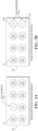
- the fan 21A in the fan array 29 is nonoperational and the fan array fault response control system 30 is controlling the speeds of all the operational fans 21 to a minimum of 0% and a maximum of 40% fan speed.
- This maximum fan speed setting is chosen typically when the spray pump 12 is energized to limit the amount of air and water splash that may otherwise come out of the nonoperational fan 21A should the fan speeds rise about 40%.
- the 40% selected maximum fan speed is adjustable depending on many factors such as configuration of the evaporative cooling device, operating conditions, operator inputs, method of control, position of nonoperational motor 21A, and other factors.
- the fans 21B of the fan array 29 are non-operational and the fan array fault response control system is controlling the speeds of all the operational motors 21 to a minimum of 0% and a maximum of 20% fan speed.
- This maximum fan speed setting is chosen typically when the spray pump 12 is energized to limit the amount of air and water splash that may otherwise come out of the nonoperational fans 21B should the fan speeds rise about 20%.
- the 20% selected maximum fan speed is adjustable depending on many factors such as configuration of the evaporative cooling device, operating conditions, operator inputs, method of control, position of non-operational fan 21 and other factors.
- the fan 21C is nonoperational and the fan array fault response control system 30 is now individually controlling the speeds of the operational fans 21 at different operational speeds.
- the speeds are being controlled based on the proximity from the nonoperational fan 21C. More specifically, the fans 21C, 21E immediately surrounding the nonoperational fan 21C are set to a maximum speed of 40% while fans 21D farther away are set to maximum speeds that will allow the unit to operate at a higher capacity while limiting air and water from exiting from the nonoperational fan 21C.
- the maximum fan speeds may be selected by the processor 31 based upon factors such as configuration of the evaporative cooling device, operating conditions, operator inputs, method of control.
- the fans 21F are non-operational and the fan array fault response control system is now individually controlling the speeds of the operational fans 21 at different operational speeds. In this case, the speeds are being controlled due to proximity from the nonoperational fans 21F. Note that the fans 21G immediately surrounding the nonoperational fans 21F are set to a maximum speed of 30%, the fans 21H farther away in the next column are set to a maximum fan speed of 40%, and the fans 211 still farther away are set to maximum speeds of 80% to 100%.
- the cooling tower 10 may operate at a higher capacity while the 30% and 40% speed limits of the fans 21G, 21H limits air and water from exiting from the non-operational fans 21F.
- the maximum fan speeds are chosen from extensive lab data and are available in the PLC program. Other factors such as configuration of the evaporative cooling device, operating conditions, operator inputs, method of control may be considered in setting the speed limit for the operational fans 21.
- the fan 21J is non-operational and the fan array fault response control system 30 has determined that it is acceptable to run the operational fans 21K up to full speed (100%) if desired. This determination may be based at least in part on the fan array fault response control system 30 determining that the spray water pump 12 is not energized, and/or that a user or the central cooling system control 44 has turned ON the override 36. On some units, when the spray water pump 12 is off or not energized, it is safe to operate all the fans 21 from 0% to 100%. When a fan 21 has become non-operational, the customer or the central cooling system control 44 can override to fan array fault response control system 30 to achieve maximum fan speeds.
- the fans 21L are non-operational and the fan array fault response control system 30 has determined that it is acceptable to run the operational fans 21L up to full speed (100%) if desired. This determination may be based at least in part on the fan array fault response control system 30 determining that the spray water pump 12 is not energized, and/or that the user or the central cooling system control 44 has turned ON the override 36.
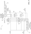
- FIG. 5 is a wiring schematic of a fan array fault response control system 200.
- the fan array fault response control system 200 includes a 24V alarm relay 202, a manual override switch 204, an override relay 206, an override light 208, and a fan alarm light 210, a fan alarm loop 212 that can be set off by any of the fans 21 or by another system input, and a fan speed control loop 214.
- the fans 21 include EC motors 22, and the components of the fan array fault response control system 200 function to remove the control signal (4-20ma) from each EC fan motor upon failure of one of the fans 21.
- the motor 22 of each operational fan 21 runs at a previously selected maximum fan speed (usually between 20 to 70% based on lab data and unit orientation).
- the fan alarm loop 212 may be closed and the fan alarm light 210 may be off.
- the fan 21 loses a control signal (which may be communicated from the fan array fault response control system 200 or a central cooling system control 44)
- the fan alarm loop 212 remains closed and the fan alarm light 212 remains off.
- the fan alarm loop 212 opens and the fan alarm light 210 turns on.
- the fan alarm loop 212 may open and the fan alarm light 210 remains off or, if on, turns off.
- contacts of the manual override switch 204 are open and the override light 208 is off.
- the contacts of the manual override switch 204 remain open.
- the contacts of the manual override switch 204 may be closed and the override light 208 may turned on.
- the override switch 204 and light 208 may not be affected by the presence or absence of a fan alarm or control signal.
- the override switch 204 may be separately actuated (either manually or by the higher level control system 44). The light 208 may only annunciate when the override switch 204 is closed and the unit is powered.
- the fan alarm loop 212 may open and the override light 208 may remain off or, if on, may turn off.
- the fan 21 may operate at a failsafe speed; for example, as requested by the fan array fault response control system 200.
- the fan array fault response control system 200 may include a wire break detection. In this way, fans 21 upstream of an internal control wire break can operate as normal, and fans 21 downstream of the internal control wire break operate at the failsafe speed.
- the fan array fault response control system 30 may operate one or more physical partitions, such as a movable cover, to reduce air and water flow through the opening associated with one or more non-operational fans 21.
- the use of physical partitions may be in addition to, or instead of, limiting the speed of the operational fans 21.
- the central cooling system control 44 includes a memory or is in communication with a cloud-based storage system to record historical data regarding the operation of the fan array fault response control system 30.
- the communication interface 38 may communicate with the central cooling system control 44 regarding instances when the system 30 limits the speed of the fans 21 and/or upon the override 36 being turned on by a user, as some examples.
Landscapes
- Engineering & Computer Science (AREA)
- Mechanical Engineering (AREA)
- General Engineering & Computer Science (AREA)
- Physics & Mathematics (AREA)
- Thermal Sciences (AREA)
- Cooling Or The Like Of Electrical Apparatus (AREA)
- Air Conditioning Control Device (AREA)
Description
- This invention relates to a heat rejection apparatus and to a method of controlling a heat rejection apparatus.
- Some heat rejection apparatuses, such as a closed-circuit cooling tower, an evaporative condenser, or an evaporative cooling tower, utilize an array of fans to generate airflow within the device. When one of the fans of the fan array fails, such as the failure of a motor associated with the fan, the operating fans continue to generate airflow within the device. For example, for a forced draft evaporative cooling unit with a fan array, one or more of the fans of the fan array may become non-operational. A non-operational fan may be completely non-operational such that the fan is unable to run at all, such as due to a complete motor failure, or partially non-operational such that the fan is unable to run at the requested speed but may still run at a reduced speed, such as due to a bearing failure or fan imbalance which limits the speed of the fan. The non-operational fan may be forced to run backwards by the operating fans. Further, the operational fans create a high pressure within the evaporative cooling device which can push air outwards through the opening of the non-operational fan and cause water to splash out through the opening. The air and water escaping through the non-operational fan may adversely affect operation of the forced draft evaporative cooling unit. Further, the water escaping through the opening of the non-operational fan may be undesirable in subfreezing climates.
- For an induced draft fan array, should one or more of the fans become nonoperational, the non-operational fan will be run backward by the operational fans. The nonoperational fan will pull air inward causing air recirculation and loss of total induced airflow.
- Historically, controlling the operation of an evaporative cooling device when one of the fans of the device fail has been controlled with physical barriers or louvers between the individual fans, which are not feasible for devices having a large array of smaller fans. Those solutions are expensive, impede access for maintenance, and can adversely affect device performance.
-
EP 2163768 A1 discloses a fan control system that controls a plurality of fans and, when a state arises wherein a fan becomes overloaded during operation, eliminates that overload. The fan control system comprises: a first fan; a second fan, which is adjacent to the first fan; a first motor, which rotates the first fan; a second motor, which rotates the second fan; and a control unit. The control unit controls the rotational speeds of the first motor and the second motor and, when the state has arisen wherein the rotational speed of the first motor must be decreased, decreases the rotational speeds of both the first motor and the second motor. -
US 2018/224174 A1 discloses a water recirculation system operates in a primary mode for evaporatively cooling air. When the water recirculation mode malfunctions, the controller switches a secondary once-through mode. The system includes a sump for collecting water run-off from the evaporative pads, and a pump in fluid communication with the sump. The pump transfers moisture from the sump to the distribution arrangement located at the top of the evaporative pads during the recirculation mode. An automatically operated make-up water valve delivers water to a distribution arrangement on the evaporative pads. A moisture distribution arrangement distributes moisture to the evaporative pads and an automatically operated sump drain valve retains water in the sump when closed and freely drains water from the sump when open. A water level control communicates the sump water level to a control system. A monitoring mechanism detects whether the water-recirculation system has malfunctioned or is operating correctly. - According to a first aspect of the present invention, defined by appended
independent claim 1, there is provided a heat rejection apparatus, such as a cooling tower, that includes a heat exchanger and a liquid distribution system configured to direct liquid toward the heat exchanger. The heat rejection apparatus includes a plurality of fans configured to generate airflow relative to the heat exchanger, a sump, and a pump operable to pump liquid from the sump to the liquid distribution system. The heat rejection apparatus further includes a controller operably coupled to the fans and configured to detect at least one non-operational fan of the plurality of fans. The controller is configured to effect a reduced fan speed of at least one operational fan of the plurality of fans upon detecting the at least one non-operational fan. The controller is operably coupled to the pump and is configured to determine whether the pump is operating. The controller is configured to effect the reduced fan speed of the at least one operational fan of the plurality of fans upon detecting the at least one non-operational fan and determining the pump is operating. The reduced fan speed of the at least one operational fan may inhibit internal air pressure near the at least one non-operational fan from causing the at least one non-operational fan to draw air and liquid outward from the heat rejection apparatus. - In another aspect of the present invention, a method is provided for controlling a heat rejection apparatus, wherein this method is defined by appended
independent claim 8. The heat rejection apparatus includes a heat exchanger, a liquid distribution system configured to direct liquid toward the heat exchanger, and a plurality of fans configured to generate airflow relative to the heat exchanger. The method includes determining at least one of the fans is non-operational and causing, upon detection of the at least one non-operational fan, at least one operational fan of the plurality of fans to rotate at a reduced fan speed. The method provides the at least one operational fan includes a plurality of operational fans, and the causing the at least one operational fan of the plurality of fans to rotate at the reduced fan speed includes causing different operational fans to rotate at different speeds based at least in part on the proximity of each operational fan to the at least one nonoperational fan. The method may thereby provide an approach to limit the liquid from being blown out of the heat rejection apparatus via the at least one non-operational fan. - To enable a better understanding of the present invention, and to show how the same may be carried into effect, reference will now be made, by way of example only, to the accompanying drawings, in which:
-
FIG. 1A is a view of a cooling tower; -
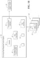
FIG. 1B is schematic view of a fan array fault response control system of the cooling tower ofFIG. 1A ; -
FIG. 2 is a flow diagram of a method of operating the fan array fault response control system ofFIG. 1B ; -
FIG. 3A is a schematic view of an eight-fan array with operational fans limited to 0% to 40% fan speed; -
FIG. 3B is a schematic view of an eight-fan array with operational fans limited to 0% to 20% fan speed; -
FIG. 4A is a schematic view of an eight-fan array where fan speeds are selectively controlled which is illustrative of the inventive method as defined by appendedindependent claim 8; -
FIG. 4B is a schematic view of an eight-fan array where fan speeds are selectively controlled which is illustrative of the inventive method as defined by appendedindependent claim 8; -
FIG. 4C is a schematic view of an eight-fan array where full fan operational speeds are permitted; -
FIG. 4D is a schematic of an eight-fan array where full fan operational speeds are permitted; and -
FIG. 5 is a wiring schematic of an example of a fan array fault response control system. - In accordance with one aspect of the present invention, as defined by appended
independent claim 1, a fan array fault response control system is provided as part of a heat rejection apparatus such as a cooling tower. The fan array fault response control system automatically detects and responds to one or more non-operational fans of a fan array of the heat rejection apparatus by means of at least the features defined in appendedindependent claim 1, without intervention by the end user of the device. The fan array fault response control system may detect and respond to a variety of faults that would prevent an individual fan motor from operating. Examples of situations that may cause a fan to become non-operational are a loss of a fan speed control signal, a failure of a fan motor, a tripped power breaker, loss of phase, failure of motor bearings, delamination of magnets, or short-circuited wiring or electronics. One or more of these situations, or other situations, may trigger remedial action by the fan array fault response control system. In one embodiment, the fan array fault response control system has an operating mode and responds to the fault by reconfiguring to a safe mode of operation. In the safe mode of operation, the fans are operated to minimize reversed airflow and water loss through the openings of the one or more non-operational fans. The safe mode of operation may include limiting all or some of the individual fans to lower speeds than normal to reduce the local air pressure acting on the non-operational fans so that the non-operational fans rotate slowly in the reverse direction or not at all. This keeps the nonoperational fans from pushing air outward from the heat rejection apparatus. Further, some operational fans may also have a minimum speed set to inhibit the operational fans from having backflow issues caused by the air pressure generated by the overall fan array. - More specifically, upon detecting a failure of one or more of the fans of the fan array, an alarm is operated. The alarm triggers a fan motor speed control system of the fan array fault response control system to set speed limits for the operational fans of the fan array. The speed limits may either be the same for all operational fans or may be different for the fans based upon a predetermined criteria. The criteria may include, for example, the location of the non-operational fans relative to the individual operational fans, whether the spray pump is operating or not, or a combination thereof. The speed limits of the operational fans can be varied to account for the overall operational state of the heat rejection apparatus. The alarm may include a local notification apparatus that is operated upon failure of one of the fans to assist a repair person in identifying the failure condition. Further, the alarm provides remote annunciation of the alarm to higher level system controls of the associated cooling system.
- Since performance requirements can vary throughout the operational life of a heat rejection apparatus, at times it may be necessary to override the safe mode of operation for the operational fans particularly in times of peak cooling demand. In one embodiment, the fan array fault response control system includes an override that provides the ability to change the fan array fault response control system to an override mode. In the override mode, the fan array fault response control system removes the limits on operational fan speeds as needed without affecting the alarm. The status of the override may be annunciated locally and/or remotely to higher level system controls of the cooling system. Once the condition triggering the alarm has been remediated, the fan array fault response control system will return to the operating mode and the fan array fault response control system will return the fans to normal operation. For example, upon the loss of a fan speed control signal at one or more of the fans, the fan array fault response control system will enter a safe mode and the one or more fans will operate at a failsafe speed. The fan array fault response control system will return to the operating mode and the one or more fans will automatically resume normal speed on restoration of the control signal.
- The fans may include one or more fans having electronically commutated (EC) motors. The EC motors are configured to send an alarm signal to the fan array fault response control system in the event of a fan failure.
- Referring now to
FIG. 1A , a heat rejection apparatus such as acooling tower 10 is provided that includes apump 12, a heat exchanger such as anindirect heat exchanger 14, aliquid distribution system 19, adrift eliminator 20, and afan array 29 including a plurality offans 21 havingmotors 22. Thecooling tower 10 has ahousing 13 that supports thefans 21 and forms aninternal compartment 13A which contains theindirect heat exchanger 14 and theliquid distribution system 19. - The
cooling tower 10 may take a variety of forms. For example, thecooling tower 10 may include a direct heat exchanger including fill sheets that receive liquid from theliquid distribution system 19 and airflow generated by thefans 21 directly cools the liquid. As another example, thecooling tower 10 may include a heat exchanger having two or more different heat exchange elements such as serpentine coils for indirectly cooling a process fluid that travels through the serpentine coils and fill sheets that receive the liquid sprayed onto the serpentine coils that permit the liquid to be directly cooled by airflow within thecooling tower 10. - The
fans 21 may each have amotor 22. As another example, afan 21 may include amotor 22 that drives thefan 21 and one or moreother fans 21. Referring momentarily toFIG. 1B , in one embodiment, thefans 21 have fan locks or keeps 23. The keeps 23 are configured to mechanically engage a portion of thefans 21, such as one or more fan blades and/or driveshafts, to inhibit rotation of the fan blades. The keep 23 associated with eachfan 21 may be actuated to inhibit rotation of the fan blades upon thefan 21 becoming non-operational and resist the fan blades from spinning in a direction that causes a vacuum and draws out from thecooling tower 10 through thenon-operational fan 21. - Returning to
FIG. 1A , thecooling tower 10 may operate wet in the evaporative mode, partially wet in a hybrid mode or can operate dry, with thespray pump 12 turned off when ambient conditions or lower loads permit. Thespray pump 12 receives the coldest cooled evaporatively sprayed fluid, usually water, fromcold water sump 11 and pumps it to theliquid distribution system 19 where the water comes out of nozzles ororifices 17 to distribute water over theindirect heat exchanger 14. Theliquid distribution system 19 andnozzles 17 operate to evenly distribute an evaporative fluid, such as water, over the top of theindirect heat exchanger 14. As the coldest water is distributed over the top ofindirect heat exchanger 14, thefans 21 of thefan array 29 force or push ambient air in underindirect heat exchanger 14, generally upward throughindirect heat exchanger 14, then throughdrift eliminators 20 which serve to prevent drift from leaving the unit. - In the
fan array 29, there are sixfans 21 and sixmotors 22 shown in this example but thatfan array 29 may include any plural number offans 21 andmotors 22, such as in the range of two and twentyfan 21/motor 22 assemblies as one example. Eachfan 21 may include fan blades 21A driven directly by amotor 22. Alternatively, eachfan 21 may be a direct driven radial style fan or may utilize a belt or gear drive. Thefans 21 may be electrocommutated (EC) fans that include circuitry configured to transmit an alarm signal in response to a failure of thefan 21. - The
fan array 29 causes air to generally flow in a counterflow direction relative to the falling water emitted from thenozzles 17. AlthoughFIG. 1A is shown withaxial fans 21 forcing or pushing air through the unit, there could additionally or alternatively be a fan array on top of the unit that induces air through the unit. - The
indirect heat exchanger 14 is shown with aninlet connection pipe 15 connected to inlet header 24 andoutlet connection pipe 16 connected tooutlet header 25. Inlet header 24 connects to the inlets of a plurality ofcoil circuits 14A whileoutlet header 25 connects to the outlet of thecoil circuits 14A. Eachcoil circuit 14A includes run lengths 14B connected withreturn bend sections 18. It should be understood that the process fluid direction may be reversed to optimize heat transfer and is not a limitation to embodiments presented. - With reference to
FIGS. 1A and1B , thecooling tower 10 has acontrol box 26 that includes a controller for an evaporative coil product such as a fan array faultresponse control system 30. The fan array faultresponse control system 30 supplies the necessary power tofan motors 22 via afan interface 42 and communicates viacommunication interface 38 with a centralcooling system control 44, which may be part of an HVAC system of a building. For example, the fan array faultresponse control system 30 may include an electrical circuit having logic provided by switches and relays. The fan array faultresponse control system 30 includes a programmable logic controller (PLC) or an application-specific integrated circuit (ASIC). The fan array faultresponse control system 30 may include hardware, such as aprocessor 31 and a non-transitory computer readable medium, such as amemory 33. As one example, thememory 33 may include random access memory (RAM), read only memory (ROM), an electrically erasable programmable read only memory (EEPROM), as some examples. The fan array faultresponse control system 30 may also include software. For example, theprocessor 31 of the fan array faultresponse control system 30 may execute computer-readable instructions stored in thememory 33. - The fan array fault
response control system 30 includes afan fault alarm 40 that communicates with thefans 21 via afan interface 42 and detects failures of thefans 21. Thefan fault alarm 40 turns on or otherwise becomes active from a signal sent from themotor 22 or could be activated from other fan operating detection methods such as a differential pressure switch, an amperage sensing current device, or a sail switch. The fan array faultresponse control system 30 has an operating mode wherein the fan array faultresponse control system 30 permits thefan interface 42 of the fan array faultresponse control system 30 to send fan speed control signals to thefans 21 according to instructions from the centralcooling system control 44. The fan speed control signals may include, for example, electrical power having a voltage and/or an amperage that is selected to provide a desired fan speed. As another example, the fan speed control signal may include a message communicated to a processor of thefan 21 and the fan-based processor directs the associatedmotor 22 to provide the desired fan speed. In one embodiment, the fan array faultresponse control system 30 is installed between thefans 21 and the centralcooling system control 44 such that the fan array faultresponse control system 30 intercepts speed control signals sent from the centralcooling system control 44 to thefans 21. - The fan array fault
response control system 30 may also operate in a safe mode, whereby the fan array faultresponse control system 30 adjusts the speed of thefan 21 from the speed requested by the centralcooling system control 44. The fan array faultresponse control system 30 further includes anoverride 36 that may be operated by the centralcooling system control 44 and reconfigures the fan array faultresponse control system 30 to an override mode. In the override mode, the fan array faultresponse control system 30 permits thefan interface 42 to send fan speed control signals to thefans 21 that produce a fan speed requested by the centralcooling system control 44. The centralcooling system control 44 may operate theoverride 36 during, for example, a high-demand situation for the associated HVAC system. - The
communication interface 38 may communicate with the centralcooling system control 44 using a number of different physical layers. In one example, the communications can be carried via a wired or bus connection or via wireless radio communication. Thecommunication interface 38 receives fan speed information from the centralcooling system control 44 and communicates the fan speed information to theprocessor 31. Theprocessor 31 is operatively coupled to thefan interface 42 of the fan array faultresponse control system 30 and causes thefan interface 42 to send fan speed control signals to themotors 22 of thefans 21. Thecommunication interface 38 may communicate information from the fan array faultresponse control system 30 to the centralcooling system control 44. For example, thecommunication interface 38 may communicate a fan fault annunciation from thefan fault alarm 40 and/or an override annunciation from theoverride 36 from the fan array faultresponse control system 30 to the centralcooling system control 44. - Regarding
FIG. 2 , amethod 100 is provided for operating the fan array faultresponse control system 30. Themethod 100 starts atoperation 101 wherein the fan array faultresponse control system 30 determines the status of theoverride 36. In one embodiment, theoverride 36 includes an electrical or a software-based switch and theoperation 100 involves checking whether the switch is turned on or turned off. The switch of theoverride 36 will be turned on upon thecommunication interface 38 receiving an override communication from the centralcooling system control 44. If theoverride 36 is turned on, the fan array faultresponse control system 30 is in the override mode. For example, a user may have requested an override at a portable computing device, e.g., a smartphone, in communication with the centralcooling system control 44. As another example, the centralcooling system control 44 may have sent an override request without user input such as if thecooling tower 10 is in a high-demand situation. The switch of theoverride 36 will remain turned on until thecommunication interface 38 receives a request to change the switch of theoverride 36 to the off position. In one embodiment, the fan array faultresponse control system 30 may include a user interface at thecooling tower 10 that permits a user to change the switch of theoverride 36 between on and off positions. - If the
override 36 is on atoperation 101, themethod 100 proceeds to set an override annunciation to ON atoperation 102. If the override annunciation was previously ON, the override annunciation will remain ON. If the override annunciation was previously OFF, the override annunciation will be turned ON. Theoperation 102 may include a making a local override OFF annunciation such as an audio or visual alert from a user interface of thecooling tower 10. Alternatively or additionally, theoperation 102 may include a remote override ON annunciation wherein thecommunication interface 38 sends an override ON annunciation communication to the centralcooling system control 44. The centralcooling system control 44 may relay the annunciation to an end user, such as building maintenance, such as via a display of thecentral cooling system 44, an SMS text message to a maintenance worker's phone, or an email to an email account associated with building maintenance. - Once the override annunciation is turned ON at
operation 102, the override annunciation will remain ON until theoverride 36 is set to OFF by a user at the user interface of thecooling tower 10 or by a communication from the centralcooling system control 44. In another embodiment, the fan array faultresponse control system 30 includes a timer that starts atoperation 102. When the timer expires, thecooling tower 10 resets the override annunciation to OFF. This limits the duration theoperation fans 21 may operate at the normal speed ranges requested by the centralcooling system control 44 when there are one or morenon-operational fans 21. In this manner, the fan array faultresponse control system 30 defaults to protecting thecooling tower 10 with anon-operational fan 21. - At
operation 103, the fan array faultresponse control system 30 detects whether thefan fault alarm 40 has an alarm condition. In the alarm condition, thefan fault alarm 40 indicates an error or fault at one or more of thefans 21. If thefan fault alarm 40 is not in the alarm condition, themethod 100 proceeds tooperation 104 wherein an alarm annunciation is set to OFF. Theoperation 104 may include a local alarm OFF annunciation, such as an audio or visual announcement, at a user interface of thecooling tower 10. Alternatively or in addition, theoperation 104 may include a remote alarm OFF annunciation such as thecontrol circuitry 38 sending an alert annunciation communication to the centralcooling system control 44. If the alarm annunciation was previously OFF, the alarm annunciation will remain OFF atoperation 103. If the alarm annunciation was previously ON, the alarm annunciation will be turned OFF atoperation 103. - The
method 100 proceeds fromoperation 104 tooperation 105 afteroperation 104. Atoperation 105, the fan array faultresponse control system 30 permits thefans 21 to operate throughout the full speed range of thefans 21. More specifically, the fan array faultresponse control system 30 permits alloperational fans 21 in thefan array 29 to operate across their normal speed range as requested by the centralcooling system control 44. Themethod 100 then returns tooperation 101 wherein the fan array faultresponse control system 30 repeats themethod 100 and continues to monitor thefans 21. - If, at
operation 103, the fan array faultresponse control system 30 detects an alarm condition of thefan fault alarm 40, themethod 100 proceeds tooperation 106. Atoperation 106, the fan array faultresponse control system 30 sets an alarm annunciation to ON. Theoperation 106 may include a local alarm ON annunciation, such as an audio or visual announcement, at a user interface of thecooling tower 10. Alternatively or in addition, theoperation 106 may include a remote alarm ON annunciation such as thecontrol circuitry 38 sending an alarm ON annunciation communication to the centralcooling system control 44. If the alarm annunciation was previously set to ON, the alarm annunciation will remain ON atoperation 106. Conversely, if the alarm annunciation was previously set to OFF, the alarm annunciation will be turned ON atoperation 106. Themethod 100 then proceeds tooperation 105 discussed above - Returning to
operation 101, if theoverride 36 is turned off, themethod 100 proceeds tooperation 107 wherein the override annunciation is set to OFF. Theoperation 107 may include a making a local override OFF annunciation such as an audio or visual alert from a user interface of thecooling tower 10. Alternatively or additionally, theoperation 107 may include a remote override OFF annunciation wherein thecommunication interface 38 sends an override OFF annunciation communication to the centralcooling system control 44. If the override annunciation was previously OFF, the override annunciation remains OFF atoperation 107. Conversely, if the override annunciation was previously ON, it will be turned OFF atoperation 107. - The
method 100 proceeds fromoperation 107 tooperation 108. Atoperation 108, the fan array faultresponse control system 30 detects whether thefan fault alarm 40 has an alarm condition. Thefan fault alarm 40 may have an alarm condition, for example, if the motor of one of thefans 21 has failed. In the alarm condition, thefan fault alarm 40 indicates an error or fault at one or more of thefans 21. If thefan fault alarm 40 is not in the alarm condition, themethod 100 proceeds tooperation 109 wherein the alarm annunciation is set to OFF. -
Operation 109 may include making a local alarm OFF annunciation, such as at a user interface of thecooling tower 10. Alternatively or in addition, theoperation 109 may include a remote alarm OFF annunciation such as thecontrol circuitry 38 sending an alarm OFF annunciation to the centralcooling system control 44. If the alarm annunciation was previously OFF, the alarm annunciation will remain OFF atoperation 109. If the alarm annunciation was previously ON, the alarm annunciation will be turned OFF atoperation 109. Once the alarm OFF annunciation has been made atoperation 109, themethod 100 proceeds tooperation 105 discussed above. - If the fan array fault
response control system 30 detects an alarm condition atoperation 108, themethod 100 proceeds tooperation 110. Atoperation 110, the fan array faultresponse control system 30 sets the alarm annunciation to ON. Theoperation 110 may include a local alarm ON annunciation, such as at a user interface of thecooling tower 10. Alternatively or in addition, theoperation 110 may include a remote alarm ON annunciation such as thecontrol circuitry 38 sending an alarm ON annunciation communication to the centralcooling system control 44. If the alarm annunciation was previously set to ON, the alarm annunciation will remain ON atoperation 110. Conversely, if the alarm annunciation was previously set to OFF, the alarm annunciation will be turned ON atoperation 110. - The
method 100 proceeds fromoperation 110 tooperation 111. Atoperation 111, alarm annunciation has been set to ON which indicates there is a fault at one or more of thefans 21 and the override annunciation has been set to OFF which indicates theoverride 36 has not been activated by a user or the centralcooling system control 44. The fan array faultresponse control system 30 therefore determines whether speed limiting is required for thefans 21. Speed limiting may be required, for example, if theprocessor 31 determines that speed limiting is required to minimize reverse airflow through nonoperational fans. As one example, theprocessor 31 may determine whether thespray pump 12 is energized and pumping water to thenozzles 17. This energization of thespray pump 12 indicates that that thecooling tower 10 is operating wet or partially wet and water is falling through the interior of thecooling tower 10. Theprocessor 31 determines that speed limiting should be employed to limit egress of water through the opening of thenonoperational fan 21. As another example, thecooling tower 10 may include an on-board vibration sensor operatively coupled to theprocessor 31. Theprocessor 31 determines that speed limiting should be employed if a sensed portion of thecooling tower 10 is vibrating with a magnitude or frequency above a predetermined threshold. If speed limiting is not required atoperation 111, themethod 100 proceeds tooperation 105 discussed above. - If speed limiting is required at
operation 111, the fan array faultresponse control system 30 limits the speed range of one or more operational fans in thefan array 29 atoperation 112. The fan array faultresponse control system 30 receives the requested fan speed for one or more of thefans 21 from thecentral cooling system 44. Because there is anon-operational fan 21 in thefan array 29, the fan array faultresponse control system 30 sends modified fan speed control signals to theoperational fans 21 to effect a slower speed of one or more of theoperational fans 21 than requested by the centralcooling system control 44. As another example, the fan array faultresponse control system 30 and thecentral cooling system 44 communicate with the one ormore fans 21 in a parallel manner. More specifically, the centralcooling system control 44 may communicate a requested fan speed to the one ormore fans 21. The fan array faultresponse control system 30 may communicate a limit speed range request to the one ormore fans 21 that takes priority over the requested fan speed communication from the centralcooling system control 44 such that the one ormore fans 21 respond to the fan array faultresponse control system 30 communication rather than the centralcooling system control 44. Theoperation 112 involves limiting fan speed in a number of ways, and the following are exemplary approaches that may be used individually or together. - First, the fan array fault
response control system 30 may limit fan speed by setting theoperational fans 21 in thefan array 29 to have the same speed. The speed selected is based upon the configuration of the evaporative cooling device, operating conditions, operator inputs, method of control, as some examples. In one embodiment, themotors 22 are EC motors and whenever the fan speed control signal is lost, themotors 22 default to a reduced predetermined speed. Theprocessor 31 may thereby limit fan speed by causing thefan interface 42 to not send a fan speed control signal to theoperational fans 21, which will force all themotors 22 to operate at the same reduced predetermined speed. In another approach, rather than sending no fan speed control signal to theoperational fans 21, the processor may cause thefan interface 42 to send the same fan speed control signal to theoperational fans 21. - A forced draft evaporative heat exchanger having a fan array fault response control system in accordance with the subject invention was tested by causing a fan of a fan array of the unit to be non-operational. With the spray pump of the forced draft evaporative heat exchange turned on, it was determined that the EC motors of the operational fans of the unit should not be operated above a maximum speed of 60% for the tested unit. The maximum fan speed for the operative fans was therefore set to a speed of between 0% to 60% of the speed requested by a central cooling system control. It should be noted that the maximum fan speed of the operational fans depends on many variables such as position of non-operational fan, proximity of evaporative cooling units to buildings and other structures and the climate to name a few variables. In another test involving a different forced draft evaporative heat exchanger unit, a fan speed limit of 40% was the maximum speed limit that could be utilized without water coming out of the nonoperational fans of the heat exchanger. In another test where the spray pump of a forced draft evaporative heat exchanger was turned off, the fan motors of operational fans of the forced draft evaporative heat exchange unit could be operated at any desired level between 0% to 100% when there is at least one non-operational fan motor in the fan array of the unit. In some applications, the fan array fault
response control system 30 may not be in communication with thespray pump 12. In this application, the fan array faultresponse control system 30 may assume that thespray pump 12 is on and limit fan speed upon failure of afan 21. - Second, the fan array fault
response control system 30 may limit fan speed by setting theoperational fans 21 in thefan array 29 to different minimum and/or maximum speeds. The fan speeds selected may be based upon the configuration of the evaporative cooling device, operating conditions, operator inputs, position of thenon-operational fans 21, as some examples. In one embodiment, themotors 22 are EC motors and the fan array faultresponse control system 30 includes a PLC. The PLC may look up preprogrammed speed values for eachoperational fan 21 based on the position of thenon-operational fans 21 in thefan array 29. By operating theoperational fans 21 individually, unit performance can be optimized when one or more of thefans 21 are non-operational in thefan array 29. - Third, the fan array fault
response control system 30 may limit fan speed by setting the same fan speed range for the all of theoperational fans 21, such as by setting minimum and/or maximum speed limits for theoperational fans 21. The fan speed range selected may be based upon the configuration of the evaporative cooling device, operating conditions, operator inputs, and/or position of thenonoperating fans 21, as some examples. By setting the same minimum and/or maximum speed limits for theoperational fans 21, theoperational fans 21 will follow the fan speed requirements from the centralcooling system control 44 as long as the fan speed requirements from the centralcooling system control 44 are within the range set by the minimum and/or maximum speed limit. Should the centralcooling system control 44 request a speed higher than a maximum set by thespeed limiting operation 112, theoperational fans 21 will run at the maximum speed allowed by thespeed limiting operation 112. If the centralcooling system control 44 requests a fan speed between the maximum speed limit and a minimum speed limit set at thespeed limiting operation 112, thefans 21 will rotate at the requested fan speed. If the centralcooling system control 44 requests a fan speed lower than the minimum speed limit set at thespeed limiting operation 112, theoperational fans 21 will run at the minimum speed allowed by thespeed limiting operation 112. As noted above, the fan array faultresponse control system 30 may set a minimum speed limit to limit air exiting through the openings of theoperational fans 21 that could occur if thecentral cooling system 44 requested stoppage of theoperational fans 21. In another embodiment, thespeed limiting operation 112 includes setting a maximum speed limit but does not include setting a minimum speed limit such that theoperational fans 21 will rotate at the speed requested by the centralcooling system control 44 as long as the requested speed is lower than the maximum speed limit. In another embodiment, thespeed limiting operation 112 includes setting a minimum fan speed but does not include setting a maximum speed limit such that theoperational fans 21 will rotate at the speed requested by the centralcooling system control 44 as long as the requested speed is higher than the minimum speed limit. - Fourth, the fan array fault
response control system 30 may limit fan speed by setting an individual fan speed range, such as by setting minimum and/or maximum fan speed limits, for eachoperational fan 21. The fan speed range for eachfan 21 may be based uponoperational fan 21 location, locations ofnon-operational fans 21, configuration of the evaporative cooling device, operating conditions, operator input, as some examples. Eachfan 21 will follow the speed requirements from the centralcooling system control 44 as long as thefan 21 is within the set fan speed range for theindividual fan 21. For example, upon the centralcooling system control 44 requesting a speed higher than the individual maximum set by thespeed limiting operation 112, theoperational fans 21 will run at the individual maximum speed allowed by thespeed limiting operation 112. The maximum speed limit and/or the minimum speed limit set at thespeed limiting operation 112 sets limits for the speeds of theoperational fans 21 as discussed above. Themethod 100 then returns tooperation 101. - In some applications, the
processor 31 is configured to operate one or more fan keeps 23 to inhibit rotation of fan blades of associatedfans 21. For example, it may be desirable to inhibit rotation of fan blades of anon-operational fan 21, fan blades of anoperational fan 21, or fan blades of both anon-operational fan 21 and anoperational fan 21. As such, theprocessor 31 may cause the keeps 23 to mechanically engage a portion of a fan 21 (e.g., fan blades and/or a driveshaft) to inhibit rotation of the fan blades. - Turning to
FIG. 3A , the fan 21A in thefan array 29 is nonoperational and the fan array faultresponse control system 30 is controlling the speeds of all theoperational fans 21 to a minimum of 0% and a maximum of 40% fan speed. This maximum fan speed setting is chosen typically when thespray pump 12 is energized to limit the amount of air and water splash that may otherwise come out of the nonoperational fan 21A should the fan speeds rise about 40%. The 40% selected maximum fan speed is adjustable depending on many factors such as configuration of the evaporative cooling device, operating conditions, operator inputs, method of control, position of nonoperational motor 21A, and other factors. - Referring to
FIG. 3B , the fans 21B of thefan array 29 are non-operational and the fan array fault response control system is controlling the speeds of all theoperational motors 21 to a minimum of 0% and a maximum of 20% fan speed. This maximum fan speed setting is chosen typically when thespray pump 12 is energized to limit the amount of air and water splash that may otherwise come out of the nonoperational fans 21B should the fan speeds rise about 20%. The 20% selected maximum fan speed is adjustable depending on many factors such as configuration of the evaporative cooling device, operating conditions, operator inputs, method of control, position ofnon-operational fan 21 and other factors. - Now referring to
FIG. 4A , the fan 21C is nonoperational and the fan array faultresponse control system 30 is now individually controlling the speeds of theoperational fans 21 at different operational speeds. In this case, the speeds are being controlled based on the proximity from the nonoperational fan 21C. More specifically, the fans 21C, 21E immediately surrounding the nonoperational fan 21C are set to a maximum speed of 40% while fans 21D farther away are set to maximum speeds that will allow the unit to operate at a higher capacity while limiting air and water from exiting from the nonoperational fan 21C. The maximum fan speeds may be selected by theprocessor 31 based upon factors such as configuration of the evaporative cooling device, operating conditions, operator inputs, method of control. - Turning to
FIG. 4B , thefans 21F are non-operational and the fan array fault response control system is now individually controlling the speeds of theoperational fans 21 at different operational speeds. In this case, the speeds are being controlled due to proximity from thenonoperational fans 21F. Note that the fans 21G immediately surrounding thenonoperational fans 21F are set to a maximum speed of 30%, the fans 21H farther away in the next column are set to a maximum fan speed of 40%, and the fans 211 still farther away are set to maximum speeds of 80% to 100%. By permitting the fans 211 to operate up to 80% of the fan speed requested by the centralcooling system control 44, thecooling tower 10 may operate at a higher capacity while the 30% and 40% speed limits of the fans 21G, 21H limits air and water from exiting from thenon-operational fans 21F. The maximum fan speeds are chosen from extensive lab data and are available in the PLC program. Other factors such as configuration of the evaporative cooling device, operating conditions, operator inputs, method of control may be considered in setting the speed limit for theoperational fans 21. - Turning to
FIG. 4C , thefan 21J is non-operational and the fan array faultresponse control system 30 has determined that it is acceptable to run theoperational fans 21K up to full speed (100%) if desired. This determination may be based at least in part on the fan array faultresponse control system 30 determining that thespray water pump 12 is not energized, and/or that a user or the centralcooling system control 44 has turned ON theoverride 36. On some units, when thespray water pump 12 is off or not energized, it is safe to operate all thefans 21 from 0% to 100%. When afan 21 has become non-operational, the customer or the centralcooling system control 44 can override to fan array faultresponse control system 30 to achieve maximum fan speeds. - Regarding
FIG. 4D , thefans 21L are non-operational and the fan array faultresponse control system 30 has determined that it is acceptable to run theoperational fans 21L up to full speed (100%) if desired. This determination may be based at least in part on the fan array faultresponse control system 30 determining that thespray water pump 12 is not energized, and/or that the user or the centralcooling system control 44 has turned ON theoverride 36. -
FIG. 5 is a wiring schematic of a fan array faultresponse control system 200. In this embodiment, there are relays that operate to control the maximum speeds of thefans 21. The fan array faultresponse control system 200 includes a24V alarm relay 202, amanual override switch 204, anoverride relay 206, anoverride light 208, and afan alarm light 210, afan alarm loop 212 that can be set off by any of thefans 21 or by another system input, and a fanspeed control loop 214. Thefans 21 includeEC motors 22, and the components of the fan array faultresponse control system 200 function to remove the control signal (4-20ma) from each EC fan motor upon failure of one of thefans 21. Upon the fan array faultresponse control system 200 removing the control signal from theoperational fans 21, themotor 22 of eachoperational fan 21 runs at a previously selected maximum fan speed (usually between 20 to 70% based on lab data and unit orientation). - During normal operation of a
fan 21, thefan alarm loop 212 may be closed and the fan alarm light 210 may be off. When thefan 21 loses a control signal (which may be communicated from the fan array faultresponse control system 200 or a central cooling system control 44), thefan alarm loop 212 remains closed and the fan alarm light 212 remains off. When thefan 21 fails or loses power, thefan alarm loop 212 opens and the fan alarm light 210 turns on. Upon loss of power to the unit (e.g., the cooling tower 10), thefan alarm loop 212 may open and the fan alarm light 210 remains off or, if on, turns off. - During normal operation of a
fan 21, contacts of themanual override switch 204 are open and theoverride light 208 is off. When thefan 21 loses a control signal, the contacts of themanual override switch 204 remain open. When thefan 21 fails or loses power, the contacts of themanual override switch 204 may be closed and theoverride light 208 may turned on. Theoverride switch 204 and light 208 may not be affected by the presence or absence of a fan alarm or control signal. Theoverride switch 204 may be separately actuated (either manually or by the higher level control system 44). The light 208 may only annunciate when theoverride switch 204 is closed and the unit is powered. - Upon loss of power to the unit (e.g., the cooling tower 10), the
fan alarm loop 212 may open and theoverride light 208 may remain off or, if on, may turn off. - Upon loss of a control signal at the
fan 21, thefan 21 may operate at a failsafe speed; for example, as requested by the fan array faultresponse control system 200. In one approach, the fan array faultresponse control system 200 may include a wire break detection. In this way,fans 21 upstream of an internal control wire break can operate as normal, andfans 21 downstream of the internal control wire break operate at the failsafe speed. - In another embodiment of the
cooling tower 10, the fan array faultresponse control system 30 may operate one or more physical partitions, such as a movable cover, to reduce air and water flow through the opening associated with one or morenon-operational fans 21. The use of physical partitions may be in addition to, or instead of, limiting the speed of theoperational fans 21. - In one embodiment, the central
cooling system control 44 includes a memory or is in communication with a cloud-based storage system to record historical data regarding the operation of the fan array faultresponse control system 30. Thecommunication interface 38 may communicate with the centralcooling system control 44 regarding instances when thesystem 30 limits the speed of thefans 21 and/or upon theoverride 36 being turned on by a user, as some examples. - While there have been illustrated and described particular embodiments of the present invention, it will be appreciated that numerous changes and modifications will occur to those skilled in the art, and it is intended for the present invention to cover all those changes and modifications which fall within the scope of the appended claims. For example, it will be appreciated that certain actions and/or operations may be described or depicted in a particular order of occurrence while those skilled in the art will understand that such specificity with respect to sequence is not actually required. It is intended that the phrase "at least one of" as used herein be interpreted in the disjunctive sense. For example, the phrase "at least one of A and B" is intended to encompass only A, only B, or both A and B.
Claims (10)
- A heat rejection apparatus (10) comprising:a heat exchanger (14);a liquid distribution system (19) configured to direct evaporative liquid toward the heat exchanger (14);a plurality of fans (21) configured to generate airflow relative to the heat exchanger (14);a sump (11) arranged to receive evaporative liquid from the heat exchanger (14);a pump (12) operable to pump (12) liquid from the sump (11) to the liquid distribution system (19);a controller operably coupled to the fans and configured to:detect at least one non-operational fan (21) of the plurality of fans (21); andeffect a reduced fan speed of at least one operational fan of the plurality of fans (21) upon detecting the at least one non-operational fan (21);wherein the controller is operably coupled to the pump (12) and is configured to determine whether the pump (12) is operating; andwherein the controller is configured to effect the reduced fan speed of the at least one operational fan of the plurality of fans (21) upon detecting the at least one non-operational fan (21) and determining the pump (12) is operating.
- The heat rejection apparatus (10) of claim 1 wherein the controller is configured to effect the reduced fan speed of the at least one operational fan of the plurality of fans (21) based at least in part on the proximity of the at least one operational fan to the at least one nonoperational fan (21), optionally wherein the at least one operational fan includes a plurality of operational fans (21)and the controller is configured to effect different reduced fan speeds for the operational fans based at least in part upon the proximity of each operational fan to the at least one non-operational fan (21).
- The heat rejection apparatus (10) of claim 1 or 2 wherein the controller is configured to:(i) effect a first reduced fan speed of the at least one operational fan upon detecting the at least one non-operational fan (21) and determining the pump (12) is operating; and(ii) effect a second fan speed of the at least one operational fan upon detecting the at least one non-operational fan (21) and determining the pump (12) is not operating.
- The heat rejection apparatus (10) of claim 1, 2 or 3, wherein:
the apparatus further comprises a keep configured to mechanically engage a portion of the at least one non-operational fan (21) and inhibit rotation of fan blades (21A) of the fan and the controller is configured to actuate the keep upon determining the at least one fan is nonoperational. - The heat rejection apparatus (10) of claim 4 wherein the heat exchanger (14) includes an inlet header (24) that receives a process fluid, an outlet header (25), and a plurality of coil circuits (14A) connecting the inlet and outlet header (25), and wherein each coil circuit (14A) includes a plurality of runs (14B) and bends (18) connecting the runs (14B).
- The heat rejection apparatus (10) of any one of claims 1 to 5 wherein the plurality of fans (21) is configured to provide a forced draft operation for the heat exchanger (14).
- The heat rejection apparatus (10) of claim 6 wherein the speed of the at least one operational fan is below the speed at which evaporative liquid would discharge from the at least one non-operational fan (21).
- A method of controlling a heat rejection apparatus (10) comprising a heat exchanger (14), a liquid distribution system (19) configured to direct liquid toward the heat exchanger (14), and a plurality of fans (21) configured to generate airflow relative to the heat exchanger (14), the method comprising:determining at least one of the fans is non-operational;causing, upon detection of the at least one non-operational fan (21), at least one operational fan of the plurality of fans (21) to rotate at a reduced fan speed;wherein the at least one operational fan includes a plurality of operational fans; andwherein causing the at least one operational fan of the plurality of fans (21) to rotate at the reduced fan speed includes causing different operational fans to rotate at different speeds based at least in part on the proximity of each operational fan to the at least one nonoperational fan (21).
- The method of claim 8 further comprising:
checking whether an override command has been received, wherein the causing the at least one operational fan of the plurality of fans (21) to rotate at the reduced fan speed includes causing the at least one operational fan to rotate at the reduced fan speed upon the override command not having been received. - The method of claim 8 further comprising:
receiving a requested fan speed for the at least one operational fan from a central system controller, wherein the causing the at least one operational fan of the plurality of fans (21) to rotate at the reduced fan speed includes causing the at least one operational fan to rotate at less than the requested fan speed from the central system controller.
Applications Claiming Priority (2)
| Application Number | Priority Date | Filing Date | Title |
|---|---|---|---|
| US201862779182P | 2018-12-13 | 2018-12-13 | |
| PCT/US2019/066263 WO2020123963A1 (en) | 2018-12-13 | 2019-12-13 | Fan array fault response control system |
Publications (4)
| Publication Number | Publication Date |
|---|---|
| EP3894775A1 EP3894775A1 (en) | 2021-10-20 |
| EP3894775A4 EP3894775A4 (en) | 2022-08-24 |
| EP3894775C0 EP3894775C0 (en) | 2024-08-21 |
| EP3894775B1 true EP3894775B1 (en) | 2024-08-21 |
Family
ID=71073664
Family Applications (1)
| Application Number | Title | Priority Date | Filing Date |
|---|---|---|---|
| EP19896781.2A Active EP3894775B1 (en) | 2018-12-13 | 2019-12-13 | Fan array fault response control system and method |
Country Status (7)
| Country | Link |
|---|---|
| US (1) | US11668534B2 (en) |
| EP (1) | EP3894775B1 (en) |
| CN (1) | CN113302445B (en) |
| AU (1) | AU2019396605B2 (en) |
| ES (1) | ES2985495T3 (en) |
| MX (1) | MX2021005799A (en) |
| WO (1) | WO2020123963A1 (en) |
Families Citing this family (7)
| Publication number | Priority date | Publication date | Assignee | Title |
|---|---|---|---|---|
| US11585603B2 (en) * | 2020-04-13 | 2023-02-21 | Anthony Staniulis, Jr. | Indirect-direct evaporative cooling and direct evaporative cooling units and method of controlling |
| US11859924B2 (en) | 2020-05-12 | 2024-01-02 | Baltimore Aircoil Company, Inc. | Cooling tower control system |
| CN116583706A (en) | 2020-10-25 | 2023-08-11 | 球体科技公司 | Cooling Apparatus and Methods |
| CN113323903B (en) * | 2021-06-18 | 2023-08-08 | 广东湾区智能终端工业设计研究院有限公司 | Method and device for hot start of fan |
| US11885342B1 (en) * | 2022-08-17 | 2024-01-30 | Siemens Industry, Inc. | Controller and method for adaptive speed control of a fan array |
| CN115779457A (en) * | 2022-12-20 | 2023-03-14 | 江苏远方动力科技有限公司 | Porous channel evaporator and air-cooled evaporative cooler |
| DE102023134798A1 (en) * | 2023-12-12 | 2025-06-12 | Ebm-Papst Mulfingen Gmbh & Co. Kg | Method for operating a flow generation system and flow generation system |
Family Cites Families (81)
| Publication number | Priority date | Publication date | Assignee | Title |
|---|---|---|---|---|
| US3922153A (en) | 1974-03-06 | 1975-11-25 | Baltimore Aircoil Co Inc | Injector type liquid cooling apparatus |
| US4085594A (en) * | 1977-02-14 | 1978-04-25 | Suntech, Inc. | Control system for cooling tower fans |
| USD253844S (en) | 1977-07-12 | 1980-01-01 | Baltimore Aircoil Company, Inc. | Water injected cooling tower |
| USD253781S (en) | 1977-07-12 | 1979-12-25 | Baltimore Aircoil Company, Inc. | Water injected cooling tower |
| US4265645A (en) | 1980-01-21 | 1981-05-05 | Baltimore Aircoil Co., Inc. | Injector type cooling tower having air discharge slots |
| US4283612A (en) | 1980-05-05 | 1981-08-11 | Baltimore Aircoil Co., Inc. | Machine guarding apparatus |
| US4530804A (en) | 1981-01-22 | 1985-07-23 | Baltimore Aircoil Company, Inc. | Forced draft cross flow, free-plenum evaporative heat exchanger |
| US4490312A (en) | 1982-08-19 | 1984-12-25 | Ceramic Cooling Tower Company | Cooling tower with interlocking tiles |
| US4543218A (en) | 1984-07-17 | 1985-09-24 | Ceramic Cooling Tower Company | Cooling tower with concrete support structure, fiberglass panels, and a fan supported by the liquid distribution system |
| US4637903A (en) | 1985-10-30 | 1987-01-20 | Ceramic Cooling Tower Company | Lightweight cooling tower |
| US4683101A (en) | 1985-12-26 | 1987-07-28 | Baltimore Aircoil Company, Inc. | Cross flow evaporative coil fluid cooling apparatus and method of cooling |
| US4737321A (en) | 1987-01-12 | 1988-04-12 | Baltimore Aircoil Company, Inc. | Air distribution system for large cooling towers |
| US4831831A (en) | 1988-02-16 | 1989-05-23 | Baltimore Aircoil Company, Inc. | Thermal storage unit with coil extension during melt |
| US4913710A (en) | 1989-05-11 | 1990-04-03 | Baltimore Aircoil Company, Inc. | Modular cooling tower |
| US4964279A (en) | 1989-06-07 | 1990-10-23 | Baltimore Aircoil Company | Cooling system with supplemental thermal storage |
| US5155961A (en) | 1989-08-14 | 1992-10-20 | Amsted Industries Incorporated | Lightweight cooling tower with cruciform columns |
| US5028357A (en) | 1989-08-14 | 1991-07-02 | Ceramic Cooling Tower Company | Lightweight cooling tower with cruciform columns |
| US5040377A (en) * | 1989-11-21 | 1991-08-20 | Johnson Service Company | Cooling system with improved fan control and method |
| US4976895A (en) | 1989-12-15 | 1990-12-11 | Ceramic Cooling Tower Company | Lightweight cooling tower with fan supported by a vertical liquid supply pipe |
| US5193352A (en) | 1991-05-03 | 1993-03-16 | Amsted Industries, Inc. | Air pre-cooler method and apparatus |
| US5150581A (en) | 1991-06-24 | 1992-09-29 | Baltimore Aircoil Company | Head pressure controller for air conditioning and refrigeration systems |
| US5180528A (en) | 1991-07-31 | 1993-01-19 | Amsted Industries Inc. | Apparatus and method for fluid distribution in a cooling tower |
| US5386709A (en) | 1992-12-10 | 1995-02-07 | Baltimore Aircoil Company, Inc. | Subcooling and proportional control of subcooling of liquid refrigerant circuits with thermal storage or low temperature reservoirs |
| US5383339A (en) | 1992-12-10 | 1995-01-24 | Baltimore Aircoil Company, Inc. | Supplemental cooling system for coupling to refrigerant-cooled apparatus |
| US5435382A (en) | 1993-06-16 | 1995-07-25 | Baltimore Aircoil Company, Inc. | Combination direct and indirect closed circuit evaporative heat exchanger |
| US5390505A (en) | 1993-07-23 | 1995-02-21 | Baltimore Aircoil Company, Inc. | Indirect contact chiller air-precooler method and apparatus |
| US5431858A (en) | 1994-04-14 | 1995-07-11 | Baltimore Aircoil Company, Inc. | Energy conserving fluid flow distribution system with internal strainer aNd method of use for promoting uniform water distribution |
| US5724828A (en) | 1995-04-21 | 1998-03-10 | Baltimore Aircoil Company, Inc. | Combination direct and indirect closed circuit evaporative heat exchanger with blow-through fan |
| US5596877A (en) | 1995-08-16 | 1997-01-28 | Baltimore Aircoil Company, Inc. | Header and coil arrangement for cooling apparatus |
| US5851446A (en) | 1996-09-09 | 1998-12-22 | Baltimore Aircoil Company, Inc. | Rigid cooling tower |
| US5902522A (en) | 1996-09-09 | 1999-05-11 | Baltimore Aircoil Company, Inc. | Rigid cooling tower and method of constructing a cooling tower |
| US6526333B1 (en) | 1997-05-13 | 2003-02-25 | Micron Technology, Inc. | Computer fan speed control system method |
| US6213200B1 (en) | 1999-03-08 | 2001-04-10 | Baltimore Aircoil Company, Inc. | Low profile heat exchange system and method with reduced water consumption |
| US6142219A (en) | 1999-03-08 | 2000-11-07 | Amstead Industries Incorporated | Closed circuit heat exchange system and method with reduced water consumption |
| US6237900B1 (en) | 1999-03-08 | 2001-05-29 | Baltimore Aircoil Company, Inc. | Rigid evaporative heat exchangers |
| US6223544B1 (en) | 1999-08-05 | 2001-05-01 | Johnson Controls Technology Co. | Integrated control and fault detection of HVAC equipment |
| US6188189B1 (en) * | 1999-12-23 | 2001-02-13 | Analog Devices, Inc. | Fan speed control system |
| US6574908B1 (en) | 2001-12-06 | 2003-06-10 | Walter Sanner | Fishing lure with spring loaded hooks |
| US6725132B2 (en) | 2002-06-20 | 2004-04-20 | Minebea Co., Ltd. | Intelligent cooling fan |
| US6932696B2 (en) * | 2003-01-08 | 2005-08-23 | Sun Microsystems, Inc. | Cooling system including redundant fan controllers |
| WO2004100336A1 (en) | 2003-05-02 | 2004-11-18 | Abb Inc. | Intelligence automatic bypass for a motor control device fault |
| US7310958B2 (en) | 2004-03-08 | 2007-12-25 | Baltimore Aircoil Company, Inc. | Control of heat exchanger operation |
| US7623028B2 (en) | 2004-05-27 | 2009-11-24 | Lawrence Kates | System and method for high-sensitivity sensor |
| US7107782B2 (en) | 2004-07-12 | 2006-09-19 | Baltimore Aircoil Company, Inc. | Evaporative heat exchanger and method |
| US7484718B2 (en) | 2006-02-13 | 2009-02-03 | Baltimore Aircoil Company, Inc | Cooling tower with direct and indirect cooling sections |
| US7779898B2 (en) | 2006-04-14 | 2010-08-24 | Baltimore Aircoil Company, Inc. | Heat transfer tube assembly with serpentine circuits |
| US7890215B2 (en) | 2006-12-22 | 2011-02-15 | Duncan Scot M | Optimized control system for cooling systems |
| US7802774B2 (en) | 2007-02-20 | 2010-09-28 | Baltimore Aircoil Company, Inc. | Cooling tower air inlet and drain pan |
| JP4254885B2 (en) | 2007-05-22 | 2009-04-15 | ダイキン工業株式会社 | Fan control system and air conditioner equipped with the fan control system |
| JP5176813B2 (en) * | 2008-09-19 | 2013-04-03 | 日本電気株式会社 | Cooling fan failure diagnosis system, failure diagnosis device, failure diagnosis method, failure diagnosis program, and cooling device |
| AU2010238347A1 (en) | 2009-04-16 | 2011-12-08 | Star Refrigeration Limited | Evaporative cooling device |
| US8774978B2 (en) | 2009-07-23 | 2014-07-08 | Siemens Industry, Inc. | Device and method for optimization of chilled water plant system operation |
| US8433450B2 (en) | 2009-09-11 | 2013-04-30 | Emerson Process Management Power & Water Solutions, Inc. | Optimized control of power plants having air cooled condensers |
| WO2011056412A2 (en) * | 2009-11-04 | 2011-05-12 | Evapco, Inc. | Hybrid heat exchange apparatus |
| US8449255B2 (en) | 2010-03-21 | 2013-05-28 | Btpatent Llc | Wind turbine blade system with air passageway |
| WO2011149487A2 (en) * | 2010-05-27 | 2011-12-01 | Johnson Controls Technology Company | Thermosyphon coolers for cooling systems with cooling towers |
| US8434746B2 (en) | 2010-07-02 | 2013-05-07 | Baltimore Aircoil Company, Inc. | Induced draft cooling tower |
| WO2012063280A1 (en) * | 2010-11-09 | 2012-05-18 | Hitachi, Ltd. | Structual fabric of a storage apparatus for mounting storage devices |
| CN202204336U (en) | 2011-07-28 | 2012-04-25 | 湖南省电力勘测设计院 | Assistant ventilating reverse flow wet type cooling tower |
| US8892223B2 (en) | 2011-09-07 | 2014-11-18 | Honeywell International Inc. | HVAC controller including user interaction log |
| WO2013059764A1 (en) | 2011-10-21 | 2013-04-25 | Prime Datum, Inc. | Direct drive fan system with variable process control |
| US20140014292A1 (en) | 2012-07-16 | 2014-01-16 | Google Inc. | Controlling data center airflow |
| US9803929B2 (en) | 2012-12-03 | 2017-10-31 | Baltimore Aircoil Company, Inc. | Indirect heat exchanger |
| US9057563B2 (en) | 2012-12-17 | 2015-06-16 | Baltimore Aircoil Company, Inc. | Cooling tower with indirect heat exchanger |
| US9057564B2 (en) | 2012-12-17 | 2015-06-16 | Baltimore Aircoil Company, Inc. | Cooling tower with indirect heat exchanger |
| US9004463B2 (en) | 2012-12-17 | 2015-04-14 | Baltimore Aircoil Company, Inc. | Cooling tower with indirect heat exchanger |
| US9255739B2 (en) | 2013-03-15 | 2016-02-09 | Baltimore Aircoil Company, Inc. | Cooling tower with indirect heat exchanger |
| US9279619B2 (en) | 2013-03-15 | 2016-03-08 | Baltimore Aircoil Company Inc. | Cooling tower with indirect heat exchanger |
| US10132577B2 (en) | 2014-01-20 | 2018-11-20 | Baltimore Aircoil Company, Inc. | Adiabatic refrigerant condenser controls system |
| US9746213B2 (en) | 2014-08-14 | 2017-08-29 | Siemens Industry, Inc | Demand flow for air cooled chillers |
| US9587885B2 (en) | 2014-10-09 | 2017-03-07 | Baltimore Aircoil Company, Inc. | Cooling tower with indirect heat exchanger |
| US9995533B2 (en) | 2015-12-03 | 2018-06-12 | Baltimore Aircoil Company, Inc. | Cooling tower with indirect heat exchanger |
| AU2017206116B2 (en) | 2016-01-08 | 2022-04-07 | Evapco, Inc. | Improvement of thermal capacity of elliptically finned heat exchanger |
| US10519960B2 (en) * | 2016-06-07 | 2019-12-31 | Microsoft Technology Licensing Llc | Fan failure detection and reporting |
| US10775117B2 (en) | 2016-09-30 | 2020-09-15 | Baltimore Aircoil Company | Water collection/deflection arrangements |
| US10571197B2 (en) | 2016-10-12 | 2020-02-25 | Baltimore Aircoil Company, Inc. | Indirect heat exchanger |
| US10415902B2 (en) | 2016-12-09 | 2019-09-17 | Baltimore Aircoil Company, Inc. | Cooling tower water distribution system |
| US10794643B2 (en) | 2016-12-19 | 2020-10-06 | Baltimore Aircoil Company, Inc. | Cooling tower wind wall system |
| US10619898B2 (en) | 2017-02-09 | 2020-04-14 | Baltimore Aircoil Company, Inc. | Water recirculation system |
| US11029093B2 (en) | 2017-03-30 | 2021-06-08 | Baltimore Aircoil Company, Inc. | Cooling tower with direct and indirect heat exchanger |
| US10619953B2 (en) | 2017-11-15 | 2020-04-14 | Baltimore Aircoil Company, Inc. | Automated control of heat exchanger operation |
-
2019
- 2019-12-13 CN CN201980082933.0A patent/CN113302445B/en active Active
- 2019-12-13 MX MX2021005799A patent/MX2021005799A/en unknown
- 2019-12-13 AU AU2019396605A patent/AU2019396605B2/en active Active
- 2019-12-13 EP EP19896781.2A patent/EP3894775B1/en active Active
- 2019-12-13 ES ES19896781T patent/ES2985495T3/en active Active
- 2019-12-13 US US16/714,044 patent/US11668534B2/en active Active
- 2019-12-13 WO PCT/US2019/066263 patent/WO2020123963A1/en not_active Ceased
Also Published As
| Publication number | Publication date |
|---|---|
| EP3894775A4 (en) | 2022-08-24 |
| ES2985495T3 (en) | 2024-11-06 |
| EP3894775A1 (en) | 2021-10-20 |
| US20200191506A1 (en) | 2020-06-18 |
| EP3894775C0 (en) | 2024-08-21 |
| AU2019396605A1 (en) | 2021-06-03 |
| CN113302445B (en) | 2024-04-02 |
| CN113302445A (en) | 2021-08-24 |
| MX2021005799A (en) | 2021-07-02 |
| AU2019396605B2 (en) | 2025-10-09 |
| US11668534B2 (en) | 2023-06-06 |
| WO2020123963A1 (en) | 2020-06-18 |
Similar Documents
| Publication | Publication Date | Title |
|---|---|---|
| AU2019396605B2 (en) | Fan array fault response control system | |
| US8779698B2 (en) | Automatic variable speed motor drive bypass | |
| US6936767B2 (en) | Apparatus for continuous cooling of electrical powered equipment | |
| CN107367014B (en) | Control method, device and system of air conditioner cluster | |
| CN110140437A (en) | Compact liquid refrigerating module for computer server | |
| JP2008291656A (en) | Fan control system and air conditioner equipped with the fan control system | |
| JP5267479B2 (en) | Air conditioning apparatus and air conditioning system | |
| JP5625640B2 (en) | Multi-unit fan drive device and failure processing method thereof | |
| US9784508B2 (en) | Method of monitoring a heat exchanger arrangement and ram air fan in an aircraft to prevent stall conditions | |
| JP2012159270A (en) | Control device, and heat pump device | |
| KR100917934B1 (en) | Self diagnosing hvac zone configuration | |
| KR102557884B1 (en) | Heat exchange control system | |
| JP2013137149A (en) | Air conditioning system | |
| CN107655142A (en) | Emergency control device and method for air conditioning unit | |
| JP2007148572A (en) | Electronic device, temperature control device, and temperature control method | |
| JP6702227B2 (en) | Vehicle cooling fan motor controller | |
| JP5959336B2 (en) | Task air conditioner | |
| JP2011153793A (en) | Communication terminal and refrigerating machine monitoring system | |
| JP2018096551A (en) | Cold water circulation system | |
| CN119755772B (en) | Wind frequency linkage control method, indoor unit, air handling system and storage medium | |
| JP2017155945A (en) | Air purification system | |
| JP4445601B2 (en) | Protective device for auger ice machine | |
| CN120176233A (en) | Air conditioning control method, device, electronic device and computer readable storage medium | |
| JP7450374B2 (en) | Pump device, inverter and control method | |
| JPH0960856A (en) | Smoke exhaust device |
Legal Events
| Date | Code | Title | Description |
|---|---|---|---|
| STAA | Information on the status of an ep patent application or granted ep patent |
Free format text: STATUS: THE INTERNATIONAL PUBLICATION HAS BEEN MADE |
|
| PUAI | Public reference made under article 153(3) epc to a published international application that has entered the european phase |
Free format text: ORIGINAL CODE: 0009012 |
|
| STAA | Information on the status of an ep patent application or granted ep patent |
Free format text: STATUS: REQUEST FOR EXAMINATION WAS MADE |
|
| 17P | Request for examination filed |
Effective date: 20210518 |
|
| AK | Designated contracting states |
Kind code of ref document: A1 Designated state(s): AL AT BE BG CH CY CZ DE DK EE ES FI FR GB GR HR HU IE IS IT LI LT LU LV MC MK MT NL NO PL PT RO RS SE SI SK SM TR |
|
| DAV | Request for validation of the european patent (deleted) | ||
| DAX | Request for extension of the european patent (deleted) | ||
| A4 | Supplementary search report drawn up and despatched |
Effective date: 20220725 |
|
| RIC1 | Information provided on ipc code assigned before grant |
Ipc: F28D 5/00 20060101ALI20220719BHEP Ipc: F28D 1/02 20060101ALI20220719BHEP Ipc: F25B 49/02 20060101ALI20220719BHEP Ipc: F25B 49/00 20060101ALI20220719BHEP Ipc: F25B 39/04 20060101ALI20220719BHEP Ipc: F04D 27/00 20060101ALI20220719BHEP Ipc: F04D 25/16 20060101ALI20220719BHEP Ipc: F28C 1/16 20060101ALI20220719BHEP Ipc: F28C 1/12 20060101ALI20220719BHEP Ipc: B01D 1/20 20060101ALI20220719BHEP Ipc: F28F 27/00 20060101ALI20220719BHEP Ipc: F28F 25/12 20060101ALI20220719BHEP Ipc: F28F 19/00 20060101AFI20220719BHEP |
|
| GRAP | Despatch of communication of intention to grant a patent |
Free format text: ORIGINAL CODE: EPIDOSNIGR1 |
|
| STAA | Information on the status of an ep patent application or granted ep patent |
Free format text: STATUS: GRANT OF PATENT IS INTENDED |
|
| RIC1 | Information provided on ipc code assigned before grant |
Ipc: F28D 5/00 20060101ALI20240219BHEP Ipc: F28D 1/02 20060101ALI20240219BHEP Ipc: F25B 49/02 20060101ALI20240219BHEP Ipc: F25B 49/00 20060101ALI20240219BHEP Ipc: F25B 39/04 20060101ALI20240219BHEP Ipc: F04D 27/00 20060101ALI20240219BHEP Ipc: F04D 25/16 20060101ALI20240219BHEP Ipc: F28C 1/16 20060101ALI20240219BHEP Ipc: F28C 1/12 20060101ALI20240219BHEP Ipc: B01D 1/20 20060101ALI20240219BHEP Ipc: F28F 27/00 20060101ALI20240219BHEP Ipc: F28F 25/12 20060101ALI20240219BHEP Ipc: F28F 19/00 20060101AFI20240219BHEP |
|
| INTG | Intention to grant announced |
Effective date: 20240327 |
|
| GRAS | Grant fee paid |
Free format text: ORIGINAL CODE: EPIDOSNIGR3 |
|
| GRAA | (expected) grant |
Free format text: ORIGINAL CODE: 0009210 |
|
| STAA | Information on the status of an ep patent application or granted ep patent |
Free format text: STATUS: THE PATENT HAS BEEN GRANTED |
|
| AK | Designated contracting states |
Kind code of ref document: B1 Designated state(s): AL AT BE BG CH CY CZ DE DK EE ES FI FR GB GR HR HU IE IS IT LI LT LU LV MC MK MT NL NO PL PT RO RS SE SI SK SM TR |
|
| REG | Reference to a national code |
Ref country code: GB Ref legal event code: FG4D |
|
| REG | Reference to a national code |
Ref country code: CH Ref legal event code: EP |
|
| REG | Reference to a national code |
Ref country code: IE Ref legal event code: FG4D |
|
| REG | Reference to a national code |
Ref country code: DE Ref legal event code: R096 Ref document number: 602019057647 Country of ref document: DE |
|
| U01 | Request for unitary effect filed |
Effective date: 20240903 |
|
| U07 | Unitary effect registered |
Designated state(s): AT BE BG DE DK EE FI FR IT LT LU LV MT NL PT RO SE SI Effective date: 20240917 |
|
| REG | Reference to a national code |
Ref country code: ES Ref legal event code: FG2A Ref document number: 2985495 Country of ref document: ES Kind code of ref document: T3 Effective date: 20241106 |
|
| U20 | Renewal fee for the european patent with unitary effect paid |
Year of fee payment: 6 Effective date: 20241121 |
|
| PG25 | Lapsed in a contracting state [announced via postgrant information from national office to epo] |
Ref country code: NO Free format text: LAPSE BECAUSE OF FAILURE TO SUBMIT A TRANSLATION OF THE DESCRIPTION OR TO PAY THE FEE WITHIN THE PRESCRIBED TIME-LIMIT Effective date: 20241121 |
|
| PG25 | Lapsed in a contracting state [announced via postgrant information from national office to epo] |
Ref country code: GR Free format text: LAPSE BECAUSE OF FAILURE TO SUBMIT A TRANSLATION OF THE DESCRIPTION OR TO PAY THE FEE WITHIN THE PRESCRIBED TIME-LIMIT Effective date: 20241122 Ref country code: PL Free format text: LAPSE BECAUSE OF FAILURE TO SUBMIT A TRANSLATION OF THE DESCRIPTION OR TO PAY THE FEE WITHIN THE PRESCRIBED TIME-LIMIT Effective date: 20240821 |
|
| PG25 | Lapsed in a contracting state [announced via postgrant information from national office to epo] |
Ref country code: IS Free format text: LAPSE BECAUSE OF FAILURE TO SUBMIT A TRANSLATION OF THE DESCRIPTION OR TO PAY THE FEE WITHIN THE PRESCRIBED TIME-LIMIT Effective date: 20241221 |
|
| PG25 | Lapsed in a contracting state [announced via postgrant information from national office to epo] |
Ref country code: HR Free format text: LAPSE BECAUSE OF FAILURE TO SUBMIT A TRANSLATION OF THE DESCRIPTION OR TO PAY THE FEE WITHIN THE PRESCRIBED TIME-LIMIT Effective date: 20240821 |
|
| PG25 | Lapsed in a contracting state [announced via postgrant information from national office to epo] |
Ref country code: RS Free format text: LAPSE BECAUSE OF FAILURE TO SUBMIT A TRANSLATION OF THE DESCRIPTION OR TO PAY THE FEE WITHIN THE PRESCRIBED TIME-LIMIT Effective date: 20241121 |
|
| PG25 | Lapsed in a contracting state [announced via postgrant information from national office to epo] |
Ref country code: RS Free format text: LAPSE BECAUSE OF FAILURE TO SUBMIT A TRANSLATION OF THE DESCRIPTION OR TO PAY THE FEE WITHIN THE PRESCRIBED TIME-LIMIT Effective date: 20241121 Ref country code: PL Free format text: LAPSE BECAUSE OF FAILURE TO SUBMIT A TRANSLATION OF THE DESCRIPTION OR TO PAY THE FEE WITHIN THE PRESCRIBED TIME-LIMIT Effective date: 20240821 Ref country code: NO Free format text: LAPSE BECAUSE OF FAILURE TO SUBMIT A TRANSLATION OF THE DESCRIPTION OR TO PAY THE FEE WITHIN THE PRESCRIBED TIME-LIMIT Effective date: 20241121 Ref country code: IS Free format text: LAPSE BECAUSE OF FAILURE TO SUBMIT A TRANSLATION OF THE DESCRIPTION OR TO PAY THE FEE WITHIN THE PRESCRIBED TIME-LIMIT Effective date: 20241221 Ref country code: HR Free format text: LAPSE BECAUSE OF FAILURE TO SUBMIT A TRANSLATION OF THE DESCRIPTION OR TO PAY THE FEE WITHIN THE PRESCRIBED TIME-LIMIT Effective date: 20240821 Ref country code: GR Free format text: LAPSE BECAUSE OF FAILURE TO SUBMIT A TRANSLATION OF THE DESCRIPTION OR TO PAY THE FEE WITHIN THE PRESCRIBED TIME-LIMIT Effective date: 20241122 |
|
| PG25 | Lapsed in a contracting state [announced via postgrant information from national office to epo] |
Ref country code: SM Free format text: LAPSE BECAUSE OF FAILURE TO SUBMIT A TRANSLATION OF THE DESCRIPTION OR TO PAY THE FEE WITHIN THE PRESCRIBED TIME-LIMIT Effective date: 20240821 |
|
| PG25 | Lapsed in a contracting state [announced via postgrant information from national office to epo] |
Ref country code: CZ Free format text: LAPSE BECAUSE OF FAILURE TO SUBMIT A TRANSLATION OF THE DESCRIPTION OR TO PAY THE FEE WITHIN THE PRESCRIBED TIME-LIMIT Effective date: 20240821 |
|
| PG25 | Lapsed in a contracting state [announced via postgrant information from national office to epo] |
Ref country code: SK Free format text: LAPSE BECAUSE OF FAILURE TO SUBMIT A TRANSLATION OF THE DESCRIPTION OR TO PAY THE FEE WITHIN THE PRESCRIBED TIME-LIMIT Effective date: 20240821 |
|
| PLBE | No opposition filed within time limit |
Free format text: ORIGINAL CODE: 0009261 |
|
| STAA | Information on the status of an ep patent application or granted ep patent |
Free format text: STATUS: NO OPPOSITION FILED WITHIN TIME LIMIT |
|
| PG25 | Lapsed in a contracting state [announced via postgrant information from national office to epo] |
Ref country code: MC Free format text: LAPSE BECAUSE OF FAILURE TO SUBMIT A TRANSLATION OF THE DESCRIPTION OR TO PAY THE FEE WITHIN THE PRESCRIBED TIME-LIMIT Effective date: 20240821 |
|
| 26N | No opposition filed |
Effective date: 20250522 |
|
| REG | Reference to a national code |
Ref country code: CH Ref legal event code: PL |
|
| PG25 | Lapsed in a contracting state [announced via postgrant information from national office to epo] |
Ref country code: CH Free format text: LAPSE BECAUSE OF NON-PAYMENT OF DUE FEES Effective date: 20241231 |
|
| PG25 | Lapsed in a contracting state [announced via postgrant information from national office to epo] |
Ref country code: IE Free format text: LAPSE BECAUSE OF NON-PAYMENT OF DUE FEES Effective date: 20241213 |
|
| U20 | Renewal fee for the european patent with unitary effect paid |
Year of fee payment: 7 Effective date: 20251119 |
|
| PGFP | Annual fee paid to national office [announced via postgrant information from national office to epo] |
Ref country code: GB Payment date: 20251120 Year of fee payment: 7 |
|
| PGFP | Annual fee paid to national office [announced via postgrant information from national office to epo] |
Ref country code: TR Payment date: 20251202 Year of fee payment: 7 |
|
| PGFP | Annual fee paid to national office [announced via postgrant information from national office to epo] |
Ref country code: ES Payment date: 20260102 Year of fee payment: 7 |