EP3894101B1 - Temperature control system - Google Patents
Temperature control system Download PDFInfo
- Publication number
- EP3894101B1 EP3894101B1 EP19849064.1A EP19849064A EP3894101B1 EP 3894101 B1 EP3894101 B1 EP 3894101B1 EP 19849064 A EP19849064 A EP 19849064A EP 3894101 B1 EP3894101 B1 EP 3894101B1
- Authority
- EP
- European Patent Office
- Prior art keywords
- pressure
- zone
- cooling
- pump
- valves
- Prior art date
- Legal status (The legal status is an assumption and is not a legal conclusion. Google has not performed a legal analysis and makes no representation as to the accuracy of the status listed.)
- Active
Links
Images


Classifications
-
- B—PERFORMING OPERATIONS; TRANSPORTING
- B21—MECHANICAL METAL-WORKING WITHOUT ESSENTIALLY REMOVING MATERIAL; PUNCHING METAL
- B21B—ROLLING OF METAL
- B21B45/00—Devices for surface or other treatment of work, specially combined with or arranged in, or specially adapted for use in connection with, metal-rolling mills
- B21B45/02—Devices for surface or other treatment of work, specially combined with or arranged in, or specially adapted for use in connection with, metal-rolling mills for lubricating, cooling, or cleaning
- B21B45/0203—Cooling
- B21B45/0209—Cooling devices, e.g. using gaseous coolants
- B21B45/0215—Cooling devices, e.g. using gaseous coolants using liquid coolants, e.g. for sections, for tubes
- B21B45/0233—Spray nozzles, Nozzle headers; Spray systems
-
- B—PERFORMING OPERATIONS; TRANSPORTING
- B21—MECHANICAL METAL-WORKING WITHOUT ESSENTIALLY REMOVING MATERIAL; PUNCHING METAL
- B21B—ROLLING OF METAL
- B21B27/00—Rolls, roll alloys or roll fabrication; Lubricating, cooling or heating rolls while in use
- B21B27/06—Lubricating, cooling or heating rolls
- B21B27/10—Lubricating, cooling or heating rolls externally
- B21B2027/103—Lubricating, cooling or heating rolls externally cooling externally
-
- B—PERFORMING OPERATIONS; TRANSPORTING
- B21—MECHANICAL METAL-WORKING WITHOUT ESSENTIALLY REMOVING MATERIAL; PUNCHING METAL
- B21B—ROLLING OF METAL
- B21B45/00—Devices for surface or other treatment of work, specially combined with or arranged in, or specially adapted for use in connection with, metal-rolling mills
- B21B45/02—Devices for surface or other treatment of work, specially combined with or arranged in, or specially adapted for use in connection with, metal-rolling mills for lubricating, cooling, or cleaning
- B21B45/0203—Cooling
- B21B45/0209—Cooling devices, e.g. using gaseous coolants
- B21B45/0215—Cooling devices, e.g. using gaseous coolants using liquid coolants, e.g. for sections, for tubes
-
- B—PERFORMING OPERATIONS; TRANSPORTING
- B21—MECHANICAL METAL-WORKING WITHOUT ESSENTIALLY REMOVING MATERIAL; PUNCHING METAL
- B21B—ROLLING OF METAL
- B21B45/00—Devices for surface or other treatment of work, specially combined with or arranged in, or specially adapted for use in connection with, metal-rolling mills
- B21B45/02—Devices for surface or other treatment of work, specially combined with or arranged in, or specially adapted for use in connection with, metal-rolling mills for lubricating, cooling, or cleaning
- B21B45/0203—Cooling
- B21B45/0209—Cooling devices, e.g. using gaseous coolants
- B21B45/0215—Cooling devices, e.g. using gaseous coolants using liquid coolants, e.g. for sections, for tubes
- B21B45/0218—Cooling devices, e.g. using gaseous coolants using liquid coolants, e.g. for sections, for tubes for strips, sheets, or plates
Definitions
- the invention relates to the field of rolling mills, in particular reducing metallurgical property transition in inline heat treatment for long rolling products, and in particular to a temperature control system and to a method of configuring a temperature control system used for cooling a rolling mill product.
- Document US 4 932 232 A discloses a spray header for cooling a strip or a roll in a rolling mill, the spray header comprising plural spray nozzles, each spray nozzle being provided with a flow control valve coupled to the spray header.
- a main supply line controlled by a shut-off valve delivers water to the spray header.
- the flow control valves of the spray nozzles are operated by a computer.
- a typical mill has fix speed centrifugal water pumps at the water treatment facility. These pumps are often very large and provide the total flow for all of the equipment of the entire rod/ bar mill at a relatively low pressure ( ⁇ 2 bar). Often the mill reheat furnace is on its own supply, since any reduction in the required pressure/flow could be catastrophic to this area. The large pump is often followed by a series of smaller booster pumps to increase the pressure depending on equipment design.
- Typical pressures are 6.0, 8.0, 10.5 and 14.0 bar: The 6.0 bar is used for rod mill water box, roughing mill roll cooling, and most other equipment. 8.0 bar is used for the high speed rolling equipment that uses tungsten carbide rolls and for processing rod quenched and tempered rebar. 10.5 bar is used for cooling bar mill plain round products using the bar mill water boxes. Finally 14.0 bar is used for quenched and tempered bar mill rebar product.
- the pressures are oversized to account for pressure losses in piping and valves used to achieve target processing conditions.
- a 'Cooling Zone' is a section of the mill to cool the product to a desired metallurgical set point before additional processing or finishing equipment.
- Standard rod mill cooling model has three (3) cooling zones. One before the No-Twist Mill (PreNTM), one after the No-Twist Mill (PostNTM) and one after the Reducing Sizing Mill (PostRSM).
- Each zone has a Pressure Reducing Valve (PRV) to help balance the required supply pressure for the zone.
- the zone pressure target is determined by the operator to achieve water box set point targets within the operating range of the valves (20 - 80% of full open position).
- a pressure transmitter located directly after the PRV, sends a signal to the PLC where a ⁇ Pressure Loop' program informs the valve to adjust and maintain the desired pressure.
- Each zone typically consists of one (1) to four (4) water boxes.
- Each rod mill waterbox is either 4.7 or 6.1 m long.
- the quantity and length of the water boxes are defined by the mills worst case processing conditions and the amount of quench time and equalization (relaxation) required to achieve the metallurgical defined set points.
- Design variables include: mill tonnage rate, max mill speed, grade set point temperature, furnace exit temperature, and number of stands.
- the worst case is a single finish dimension being processed at the fastest tonnage rate with the longest cooling requirement. All other cases require less water contact time. This equates to less cooling length since each product speed is roughly fixed.
- the rod mill cooling nozzle typical design pressure is 2.0 bar.
- a minimum pressure ⁇ 0.5 bar
- the product cooling is not effective in penetrating the steam jacket (created by the Leidenfrost effect) and cooling the product.
- the pressure is too high ( ⁇ 3.0 bar) the product surface is over-quenched and an undesirable allotrope of steel called martensite can form.
- a minimum water pressure of 5.0 bar is the design parameter to create martensite on the surface of the finished rod product.
- Bar mill cooling nozzles are of a different design and require a high pressure to overcome its significant pressure loss.
- the bar mill set point pressures for plain carbon and quenched and tempered are 7.0 and 12.0 bar respectively.
- the batch process is consistently rethreaded for each billet.
- the front end, and in some cases tail end, must be hot to prevent the product from cobbling and achieve proper laying pattern onto the cooling conveyor correctly.
- This threading length is called the 'hot length' since it is roughly the same temperature as the furnace exit billet temperature.
- the water boxes are turned off as the head passes though.
- the time between the finish of the previous product and the start of the next (billet gap) can be as short as 2 seconds.
- a 3-Way Divert Valve is used. After the hot length passes, the 3-Way Divert Valve is then shifted quickly to redirect water to the product.
- the 'hot length' distance is an operator input value in the ETCS and is determined by: product cross sectional dimension, and distances between controlling equipment. Once the water is directed to the product, a period of time occurs for the water to reach the set point pressure/ flow. This period of time is called the 'transition length' where final metallurgical properties have not yet been achieved.
- the transition length is cooler than the 'hot length' and typically looks the same temperature as the set point temperature of the finished product.
- the predominate method to determine the transition length is to cut several tensile strength samples and record the tensile strength as it reaches the set point value. Transition of scale thickness can also be an indicator of where the transition length begins and ends. Depending on end user's quality expectations; most mills must trim the 'hot' and 'transition length' to give the end user customer the desired product
- a temperature control system used for cooling a rolling mill product according to claim 1.
- the invention involves a system that increases front end uniformity of metallurgical properties and scale control for inline heat treatment of long rolling products by moving isolation valves closer to the cooling operation.
- Isolation valves are mounted to the waterbox or within close proximity of the cooling nozzle.
- Each isolation valve is associated with a single cooling nozzle. This offers a more discrete control of cooling length which will increase cooling efficiency.
- the isolation valve is able to open and close full stroke in less than a second which minimizes the time required for the cooling nozzle to achieve set point pressure.
- a pressure reducing valve is incorporated to alleviate supply pressure differentials due to operation of other cooling zones or equipment.
- a variable frequency drive pump is able to adjust the supply pressure to meet the set point temperature in order to achieve target temperature for single and / or multiple zones.
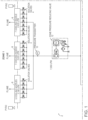
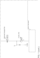
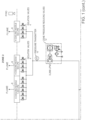
- FIG. 1 is a schematic diagram illustrating the inventive temperature control system 2 used in accordance with the invention.
- Valve reaction time is improved by reducing the distance of the current location of 3-Way Divert Valve ( ⁇ 3 m) from the process.
- the new isolation valve 4 is to be located on the outside of each water box 6 ( ⁇ 0.5 m) that corresponds to a number of nozzles. This reduction in distance improves the acceleration of water pressure to reach steady state at the cooling nozzle by approximately 1 second; for an average mean ring diameter of 1060 mm this equates to ⁇ 36 Rings at 120 M/s.
- Each zone 1, 2, and 3 includes their respective water boxes 6.
- the isolation valve 4 response from fully closed to fully open ( ⁇ 290 ms), matches closely to the guaranteed of the modified Fisher 3-Way Divert Valve ( ⁇ 300 ms) used in the prior art. This is possible since the size of the 2" isolation valve is significantly smaller than the 4 to 8" Fisher 3-Way Divert Valve. Since the isolation valve's 4 maximum dimension is 2"; it can only effectively process water suitable enough for one cooling nozzle. This means that there can only be one (1) secondary valve for each cooling nozzle. This greatly increases process control by giving the ability to uniformly predict how much pressure/flow is changed when a valve is actuated.
- VFD Variable Frequency Drive
- the zone PRVs 12 modulate the pressure as rolling condition parameters change based on zone entry and finishing temperatures.
- the zone entry temperature can help predict what is required while the zone exit pyrometer can fine tune the required finish temperature. Since the process needs to maintain the pressure between a range (0.5 and 3.0 bar for rod mills) a pressure transmitter is needed for each zone. In the event the water pressure falls below the required minimum for the zone the isolation valve will close to consolidate the cooling toward the finishing end of the zone.
- the zone PRVs 12 are used to set the water pressure for the zones 1, 2, and 3. Each zone 1, 2, or 3 is able to have different set points depending on processing conditions. It is critical that the supply pressure for each zone is maintained so that the process has the correct pressure set points for each zone.
- the pressure transmitters 10 offer ⁇ 1 millisecond response time which is much faster than the 145 millisecond response rate of the Rosemount 2088.
- the accuracy of the pressure 10 is ⁇ +/- 0.17 bar typical (+/- 0.34 bar max) a comparison to the standard Rosemount 2088 (+/- 0.14 bar) transmitter must be further evaluated.
- the Rosemount 2088 transmitter requires an expensive HART 475 communicator to set the device. The accuracy should be sufficient enough for the process. By focusing the modulation control to be based on temperature with a pressure reference the overall cost of the system can be drastically reduced. The expensive flowmeter with HART 475 communicator is no longer required.
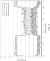
- FIG. 5 shows the existing 3-Way Divert Valve response rate against the two (2) leading contenders.
- FIG. 5 shows the existing 3-Way Divert Valve response rate against the two (2) leading contenders.
- six (6) valves were evaluated. Data points have been averaged to show comparative response rate to each other Actual data displays an overshoot and recovery before reaching steady state pressure.
- a key difference in response time is the location of the valves.
- the ASCO and Ross Dale CX isolation valves are located close to the process where as the Fisher 3-Way Divert Valve is located 8 m away. When the valves are closer to the operation the response is improved.
- This valve is an industrial valve used in paper mill applications to process thick slurries. It has a piston, 90 mm operator, which creates a positive seal when closed. The valve is available in fail open or fail closed default positions.
- the valve requires an externally mounted actuator; the ASCO 8317 was selected for its fast response rate and high flow coefficient value.
- the actuator is operated by a 24 Volt DC electrical supply and 4.1 bar instrument air supply, which is typical of rolling mill conditions.
- the valve data sheet claims to have 0.290 second response rate. Throughout testing this appeared to be consistently true even after cycle 500,000 cycles (1 year of typical production). Technical professionals at ASCO have claimed that this valve should be able to operate 1 million cycles without maintenance.
- the VFD Pump 8 is used to control torque when flow change is required while maintaining stable supply pressure. Pump selection discussed in this report only account for variable head. When the static head speed is reduced to a point where the flow is 0 LPM; the system pressure is equal to static head pressure. The static head pressure will vary depending on piping and elevation.
- the VFD Pump 8 selected allows the process to deadhead for short period of time ( ⁇ 30 seconds) without increasing pressure. When the system must deadhead for more than 30 seconds the pump can shut off. In figure 10, the flow decreases with the change in speed from point A to point B. Due to affinity laws: motor speed is proportional to the cube root of the motor power. Therefore the power consumption decreases with decreasing flow demand.
- BEP Best Efficiency Point
- the BEP is a point on the pump curve where the efficiency is the highest. At this point, the impeller is subjected to minimum radial force promoting a smooth operation with low vibration and noise. When the flow conditions change the efficiency is degraded for that pump. Armstrong double volute pump with VFD is selected increase process capabilities as flow requirements change.
- the invention improves acceleration of water pressure to reach steady state conditions to minimize transition length and achieve desired metallurgical properties of the final product.
- the invention replaces the large and expensive 3- Way Divert Valves with several smaller isolation valves close to the rolling process. By strategically placing the isolation valves closer to the cooling process, the lag time to achieve desired set point temperatures has been decreased significantly.
- the supply pumps must be variable frequency driven in order to accommodate the 'dead heading' and maintain pressure set points with increased accuracy.
Landscapes
- Engineering & Computer Science (AREA)
- Mechanical Engineering (AREA)
- Heat Treatments In General, Especially Conveying And Cooling (AREA)
- Furnace Housings, Linings, Walls, And Ceilings (AREA)
- Carbon Steel Or Casting Steel Manufacturing (AREA)
Description
- The invention relates to the field of rolling mills, in particular reducing metallurgical property transition in inline heat treatment for long rolling products, and in particular to a temperature control system and to a method of configuring a temperature control system used for cooling a rolling mill product.
- Document
US 4 932 232 A discloses a spray header for cooling a strip or a roll in a rolling mill, the spray header comprising plural spray nozzles, each spray nozzle being provided with a flow control valve coupled to the spray header. A main supply line controlled by a shut-off valve delivers water to the spray header. The flow control valves of the spray nozzles are operated by a computer. - Prior to 1980 the system had a very crude temperature control which relied heavily on operators to make adjustments when temperature set point changes where required. The pressures where then fixed for the rolling process and did not adapt to the change in process conditions (furnace exit temperature, change in product dimension, water temperature etc.). The current system, in use since the mid-1980s, uses an operator defined recipe system and is able to automate the cooling process by obtaining information from the zone finishing pyrometer and provide small incremental changes to the modulating valve as processing conditions change over time.
- A typical mill has fix speed centrifugal water pumps at the water treatment facility. These pumps are often very large and provide the total flow for all of the equipment of the entire rod/ bar mill at a relatively low pressure (~2 bar). Often the mill reheat furnace is on its own supply, since any reduction in the required pressure/flow could be catastrophic to this area. The large pump is often followed by a series of smaller booster pumps to increase the pressure depending on equipment design. Typical pressures are 6.0, 8.0, 10.5 and 14.0 bar: The 6.0 bar is used for rod mill water box, roughing mill roll cooling, and most other equipment. 8.0 bar is used for the high speed rolling equipment that uses tungsten carbide rolls and for processing rod quenched and tempered rebar. 10.5 bar is used for cooling bar mill plain round products using the bar mill water boxes. Finally 14.0 bar is used for quenched and tempered bar mill rebar product. The pressures are oversized to account for pressure losses in piping and valves used to achieve target processing conditions.
- A 'Cooling Zone' is a section of the mill to cool the product to a desired metallurgical set point before additional processing or finishing equipment. For each zone there is an exit pyrometer in which the operator defines the set point temperature. Standard rod mill cooling model has three (3) cooling zones. One before the No-Twist Mill (PreNTM), one after the No-Twist Mill (PostNTM) and one after the Reducing Sizing Mill (PostRSM). Each zone has a Pressure Reducing Valve (PRV) to help balance the required supply pressure for the zone. The zone pressure target is determined by the operator to achieve water box set point targets within the operating range of the valves (20 - 80% of full open position). A pressure transmitter, located directly after the PRV, sends a signal to the PLC where a `Pressure Loop' program informs the valve to adjust and maintain the desired pressure.
- Each zone typically consists of one (1) to four (4) water boxes. Each rod mill waterbox is either 4.7 or 6.1 m long. The quantity and length of the water boxes are defined by the mills worst case processing conditions and the amount of quench time and equalization (relaxation) required to achieve the metallurgical defined set points. Design variables include: mill tonnage rate, max mill speed, grade set point temperature, furnace exit temperature, and number of stands. The worst case is a single finish dimension being processed at the fastest tonnage rate with the longest cooling requirement. All other cases require less water contact time. This equates to less cooling length since each product speed is roughly fixed. The rod mill cooling nozzle typical design pressure is 2.0 bar.
- When the water pressure is less than a minimum pressure (~0.5 bar); the product cooling is not effective in penetrating the steam jacket (created by the Leidenfrost effect) and cooling the product. When the pressure is too high (~3.0 bar) the product surface is over-quenched and an undesirable allotrope of steel called martensite can form. In the case of the quenched and tempered process in rod mills, a minimum water pressure of 5.0 bar is the design parameter to create martensite on the surface of the finished rod product. Bar mill cooling nozzles are of a different design and require a high pressure to overcome its significant pressure loss. The bar mill set point pressures for plain carbon and quenched and tempered are 7.0 and 12.0 bar respectively.
- Since the finished product is made from billets, the batch process is consistently rethreaded for each billet. The front end, and in some cases tail end, must be hot to prevent the product from cobbling and achieve proper laying pattern onto the cooling conveyor correctly. This threading length is called the 'hot length' since it is roughly the same temperature as the furnace exit billet temperature. To keep the 'hot length' at elevated temperatures, the water boxes are turned off as the head passes though. The time between the finish of the previous product and the start of the next (billet gap) can be as short as 2 seconds. In order to divert the water flow away from the product quickly, a 3-Way Divert Valve is used. After the hot length passes, the 3-Way Divert Valve is then shifted quickly to redirect water to the product.
- The 'hot length' distance is an operator input value in the ETCS and is determined by: product cross sectional dimension, and distances between controlling equipment. Once the water is directed to the product, a period of time occurs for the water to reach the set point pressure/ flow. This period of time is called the 'transition length' where final metallurgical properties have not yet been achieved.
- The transition length is cooler than the 'hot length' and typically looks the same temperature as the set point temperature of the finished product. The predominate method to determine the transition length is to cut several tensile strength samples and record the tensile strength as it reaches the set point value. Transition of scale thickness can also be an indicator of where the transition length begins and ends. Depending on end user's quality expectations; most mills must trim the 'hot' and 'transition length' to give the end user customer the desired product
- According to one aspect of the invention, there is provided a temperature control system used for cooling a rolling mill product according to
claim 1. - According to another aspect of the invention, there is provided a method of configuring a temperature control system used for cooling a rolling mill product according to
claim 5. -
-
FIG. 1 is a schematic diagram illustrating the inventive temperature control system used in accordance with the invention; -
FIG. 2 is a graph illustrating the performance of a fixed speed centrifugal pump used in accordance with the invention; -
FIG. 3 is a graph illustrating the performance of a zone pressure reducing valve (PRV) used in accordance with the invention; -
FIG. 4 is a graph illustrating the performance of a Variable Frequency Drive (VFD) pump used in accordance with the invention; -
FIG. 5 is a graph illustrating the activation response of multiple isolation valves used in accordance with the invention; -
FIG. 6 is a graph illustrating the second response of a Ross Dale CX Valve using 4.1 bar pilot air pressure and no downstream resistance; -
FIG. 7 is a graph illustrating the second response of a ASCO 8290 With 90 mm Operator 4.1 bar pilot air pressure and 17.5 mm cooling nozzle downstream resistance; and -
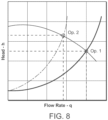
FIG. 8 is a graph illustrating a fixed speed pump using a downstream control valve. - The invention involves a system that increases front end uniformity of metallurgical properties and scale control for inline heat treatment of long rolling products by moving isolation valves closer to the cooling operation. Isolation valves are mounted to the waterbox or within close proximity of the cooling nozzle. Each isolation valve is associated with a single cooling nozzle. This offers a more discrete control of cooling length which will increase cooling efficiency. The isolation valve is able to open and close full stroke in less than a second which minimizes the time required for the cooling nozzle to achieve set point pressure. A pressure reducing valve is incorporated to alleviate supply pressure differentials due to operation of other cooling zones or equipment. A variable frequency drive pump is able to adjust the supply pressure to meet the set point temperature in order to achieve target temperature for single and / or multiple zones.
-
FIG. 1 is a schematic diagram illustrating the inventivetemperature control system 2 used in accordance with the invention. Valve reaction time is improved by reducing the distance of the current location of 3-Way Divert Valve (~3 m) from the process. Thenew isolation valve 4 is to be located on the outside of each water box 6 (<0.5 m) that corresponds to a number of nozzles. This reduction in distance improves the acceleration of water pressure to reach steady state at the cooling nozzle by approximately 1 second; for an average mean ring diameter of 1060 mm this equates to ~36 Rings at 120 M/s. Eachzone respective water boxes 6. - The
isolation valve 4 response, from fully closed to fully open (~290 ms), matches closely to the guaranteed of the modified Fisher 3-Way Divert Valve (~300 ms) used in the prior art. This is possible since the size of the 2" isolation valve is significantly smaller than the 4 to 8" Fisher 3-Way Divert Valve. Since the isolation valve's 4 maximum dimension is 2"; it can only effectively process water suitable enough for one cooling nozzle. This means that there can only be one (1) secondary valve for each cooling nozzle. This greatly increases process control by giving the ability to uniformly predict how much pressure/flow is changed when a valve is actuated. - When the
isolation valve 4 is closed the water pressure will be slightly higher than the required cooling set point. This increase in water pressure will change depending on the set point pressure. It has been observed that for 2.0 bar set point; the increased change in pressure is ~0.5 bar. - Since the water is no longer being diverted, the process will now stop the flow ('dead head') rather than divert the flow. When the downstream valves offer more resistance; the pressure after the pump will increase. Using a fixed speed pump, the pressure can only be increased by a factory determined set tolerance before the shut-off pressure is reached, as shown in
FIG. 2 . Once this upper limit has been obtained the pump must shut down or divert some flow to prevent damage to the pump. In order to keep the process running an AutomaticRecirculation Control valve 14 is installed. - With a Variable Frequency Drive (VFD)
pump 8, the process can continue to run for short periods of time while the system is dead headed to protect the water pumps from electrical/mechanical overload. Utilizing aVFD pump 8 reduces waste by only providing the pressure required; rather than having a fixed speed booster pump designed only for the worst case scenario water pressures and flows. TheVFD 8 pumps provide the rolling mill with better energy efficiency and reduced water consumption that requires filtration and cooling. TheVFD 8 pumps also provide better set point pressure stability. An Armstrong VFD Pump, as shown inFIG. 4 offers better control of water pressure for the same degree of change in process variable compared to the pressure reducing valve (PRV), as shown inFIG. 3 . - For typical rod mill systems: only a single VFD pump per strand is needed. Having separate supply pumps allows each strand to run independent of each other's processing conditions. Installing a standby pump is recommended to maintain production capability.
- By removing the standard 3-Way Divert Valve and utilizing the
VFD pump 8; the Back Pressure Valve (BPV) and its control loop is no longer required. This reduces the complexity of the system by delivering the required set point pressure without additional controls. - By treating an
entire zone - The
zone PRVs 12 modulate the pressure as rolling condition parameters change based on zone entry and finishing temperatures. The zone entry temperature can help predict what is required while the zone exit pyrometer can fine tune the required finish temperature. Since the process needs to maintain the pressure between a range (0.5 and 3.0 bar for rod mills) a pressure transmitter is needed for each zone. In the event the water pressure falls below the required minimum for the zone the isolation valve will close to consolidate the cooling toward the finishing end of the zone. - The
zone PRVs 12 are used to set the water pressure for thezones zone - The
pressure transmitters 10 offer <1 millisecond response time which is much faster than the 145 millisecond response rate of the Rosemount 2088. However, the accuracy of thepressure 10 is <+/- 0.17 bar typical (+/- 0.34 bar max) a comparison to the standard Rosemount 2088 (+/- 0.14 bar) transmitter must be further evaluated. The Rosemount 2088 transmitter requires an expensive HART 475 communicator to set the device. The accuracy should be sufficient enough for the process. By focusing the modulation control to be based on temperature with a pressure reference the overall cost of the system can be drastically reduced. The expensive flowmeter with HART 475 communicator is no longer required. - Several types of valves were tested in order to find the best fit for the invention.
FIG. 5 shows the existing 3-Way Divert Valve response rate against the two (2) leading contenders. In total six (6) valves were evaluated. Data points have been averaged to show comparative response rate to each other Actual data displays an overshoot and recovery before reaching steady state pressure. A key difference in response time is the location of the valves. In this test; the ASCO and Ross Dale CX isolation valves are located close to the process where as the Fisher 3-Way Divert Valve is located 8 m away. When the valves are closer to the operation the response is improved. - Fisher 3-Way Divert Valve claims to have 0.300 second actuation time. Through testing it was found that the valve does actuate within the 0.300 seconds however; the response rate to achieve steady state pressure is significantly longer than initially expected. Due to the distance of the pipe length (7.7 m) and increased resistance of altitude (2.3 m) the response rate is delayed significantly. In the test setup 1.3 seconds was required to achieve design pressure (2.0 bar).
- Ross Dale CX valve claimed to have 0.014 second response rate. Although some testing proved this to be true the valve can only operate if the pilot air supply is higher than the working pressure of the medium. Therefore for 2.0 bar water operating conditions the typical design of 4.1 bar of air is sufficient. However, as the conditions change and higher water pressures are required, the 4.1 bar air pressure is not strong enough to consistently close the valve. After cycle testing, half year (~250,000) cycles, the response rate was diminished and the seals needed to be replaced. In
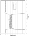
FIG. 6 , the downstream outlet is connected to a globe valve which is fully open. When the valve is open (between seconds 10.25 and 12.5 seconds) the inlet to the valve pressure drops ~3.5 bar and outlet pressure after the valve is ~3 bar. When the valve closes the inlet pressure increases and the outlet pressure never completely drops to 0 bar. At 4.1 bar pilot air supply, there is insufficient air pressure to close the valve. - This valve is an industrial valve used in paper mill applications to process thick slurries. It has a piston, 90 mm operator, which creates a positive seal when closed. The valve is available in fail open or fail closed default positions. The valve requires an externally mounted actuator; the ASCO 8317 was selected for its fast response rate and high flow coefficient value. The actuator is operated by a 24 Volt DC electrical supply and 4.1 bar instrument air supply, which is typical of rolling mill conditions. The valve data sheet claims to have 0.290 second response rate. Throughout testing this appeared to be consistently true even after cycle 500,000 cycles (1 year of typical production). Technical professionals at ASCO have claimed that this valve should be able to operate 1 million cycles without maintenance. The standard design of 4.1 bar of pilot air pressure is sufficient to close the valve to the guaranteed 6.2 bar incoming water pressure. Higher operating water pressures of 8.0 bar have been observed and the valve continues to perform as designed. In
FIG. 7 , the downstream outlet is connected to a 17.5 mm bore cooling nozzle. When the valve is open (betweenseconds 9 and 11.25 seconds) the inlet to the valve pressure drops ~1.5 bar and outlet pressure after the valve is ~5.6 bar, when the valve closes the inlet pressure increases and the outlet pressure drops to 0 bar at 4.1 bar pilot air supply, the valve is able to close - With a fixed speed pump, as the downstream control valve begins to close to decrease product cooling; the water pressure begins to increase as the total water requirement is reduced. In
FIG. 8 , the pressure starting at operation point 1 (Op.1) increases to operation point (Op.2) as the downstream water requirement is reduced. The motor power remains relatively constant and the flow decreases. - The
VFD Pump 8 is used to control torque when flow change is required while maintaining stable supply pressure. Pump selection discussed in this report only account for variable head. When the static head speed is reduced to a point where the flow is 0 LPM; the system pressure is equal to static head pressure. The static head pressure will vary depending on piping and elevation. - The
VFD Pump 8 selected allows the process to deadhead for short period of time (<30 seconds) without increasing pressure. When the system must deadhead for more than 30 seconds the pump can shut off. In figure 10, the flow decreases with the change in speed from point A to point B. Due to affinity laws: motor speed is proportional to the cube root of the motor power. Therefore the power consumption decreases with decreasing flow demand. - By installing a
pressure transmitter 10 downstream of thepump 8 and relaying information back to the drive, constant pressure can be maintained while the flow is decreasing. Through extensive testing of flow characteristics of the cooling nozzles the pressure vs flow relationship for various bore sizes has been defined. Using this data as the pump system curve; electrical and automation can map the required speed (or torque) to meet the E&A process set point. - In order to optimize pump selection, the Best Efficiency Point (BEP) is used. The BEP is a point on the pump curve where the efficiency is the highest. At this point, the impeller is subjected to minimum radial force promoting a smooth operation with low vibration and noise. When the flow conditions change the efficiency is degraded for that pump. Armstrong double volute pump with VFD is selected increase process capabilities as flow requirements change.
- The invention improves acceleration of water pressure to reach steady state conditions to minimize transition length and achieve desired metallurgical properties of the final product. First, the invention replaces the large and expensive 3- Way Divert Valves with several smaller isolation valves close to the rolling process. By strategically placing the isolation valves closer to the cooling process, the lag time to achieve desired set point temperatures has been decreased significantly. Furthermore, the supply pumps must be variable frequency driven in order to accommodate the 'dead heading' and maintain pressure set points with increased accuracy.
- Although the present invention has been shown and described with respect to several preferred embodiments thereof, various changes, omissions and additions to the form and detail thereof, may be made therein, without departing from the scope of the invention as defined by the appended claims.
Claims (8)
- A temperature control system (2) used for cooling a rolling mill product comprising:- a plurality of isolation valves (4) that are directly coupled to one or more water boxes (6);wherein the isolation valves (4) are located on the outside of the one or more water boxes (6) to reduce the time required to build up pressure for cooling and reducing the metallurgical property transition length of the rolling mill product,wherein the one or more water boxes (6) comprise a plurality of cooling nozzles for cooling the rolling mill product,wherein each of the cooling nozzles corresponds to one isolation valve (4), andwherein the one or more water boxes (6) are grouped into a plurality of zones,- a plurality of zone pressure reducing valves (12) to alleviate supply pressure differentials,wherein the zone pressure reducing valves (12) are configured to modulate the pressure based on the zone entry and finishing temperatures, andwherein zone pressure reducing valves (12) are configured to deliver the required zone pressure set point;- a plurality of pressure transmitters (10) positioned at each zone to detect its pressure; and- at least one pump (8) that is coupled to the isolation valves (4), the pump configured to provide the pressure needed for cooling.
- The temperature control system (2) of claim 1, wherein the pump (8) comprises a Variable Frequency Drive (VFD) pump.
- The temperature control system (2) of claim 1, wherein the pump (8) delivers the required set point pressure without additional control.
- The temperature control system (2) of claim 1 further comprising a plurality of zone VFD control pumps (8) that modulate the rolling mill condition parameters based on the zone entry and finishing temperatures.
- A method of configuring a temperature control system (2) used for cooling a rolling mill product comprising:- positioning a plurality of isolation valves (4) that are directly coupled to one or more water boxes (6),wherein the isolation valves (4) are located on the outside of the one or more water boxes (6) to reduce the time required to build up pressure for cooling and reducing the metallurgical property transition length of the rolling mill product;wherein the one or more water boxes (6) comprise a plurality of cooling nozzles for cooling the rolling mill product,wherein the one or more water boxes (6) are grouped into a plurality of zones, andwherein each of the cooling nozzles corresponds to one isolation valve (4);- wherein the temperature control system (2) further comprises a plurality of zone pressure reducing valves (12) to alleviate supply pressure differentials,wherein the zone pressure reducing valves (12) are configured to modulate the pressure based on the zone entry and finishing temperatures, andwherein the zone pressure reducing valves (12) are configured to deliver the required zone pressure set point;- positioning a plurality of pressure transmitters (10) at each zone to detect its pressure; and- coupling at least one pump (8) to the isolation valves (4) to provide the pressure needed for cooling.
- The method of claim 5, wherein the at least one pump (8) comprises a Variable Frequency Drive (VFD) pump.
- The method of claim 5, further comprising configuring the at least one pump (8) to deliver the required set point pressure without additional control.
- The method of claim 5 further comprising coupling a plurality of zone VFD control pumps (8) that modulate the rolling mill condition parameters based on the zone entry and finishing temperatures.
Applications Claiming Priority (3)
| Application Number | Priority Date | Filing Date | Title |
|---|---|---|---|
| US201862778486P | 2018-12-12 | 2018-12-12 | |
| US16/559,884 US20200188975A1 (en) | 2018-12-12 | 2019-09-04 | Temperature control system |
| PCT/US2019/064374 WO2020123217A1 (en) | 2018-12-12 | 2019-12-04 | Temperature control system |
Publications (2)
| Publication Number | Publication Date |
|---|---|
| EP3894101A1 EP3894101A1 (en) | 2021-10-20 |
| EP3894101B1 true EP3894101B1 (en) | 2024-03-06 |
Family
ID=71072104
Family Applications (1)
| Application Number | Title | Priority Date | Filing Date |
|---|---|---|---|
| EP19849064.1A Active EP3894101B1 (en) | 2018-12-12 | 2019-12-04 | Temperature control system |
Country Status (5)
| Country | Link |
|---|---|
| US (1) | US20200188975A1 (en) |
| EP (1) | EP3894101B1 (en) |
| CN (1) | CN113165036B (en) |
| ES (1) | ES2981232T3 (en) |
| WO (1) | WO2020123217A1 (en) |
Citations (8)
| Publication number | Priority date | Publication date | Assignee | Title |
|---|---|---|---|---|
| KR100679081B1 (en) | 2005-09-02 | 2007-02-05 | 주식회사 포스코 | Cooling device and cooling method of hot rolled steel sheet |
| US20100312399A1 (en) | 2007-09-27 | 2010-12-09 | Udo Borgmann | Operating method for a cooling section having centralized detection of valve characteristics and objects corresponding thereto |
| CN102069097A (en) | 2011-01-20 | 2011-05-25 | 马鞍山钢铁股份有限公司 | System and process for cooling after H-shaped steel is hot-rolled |
| CN103861879A (en) | 2014-03-28 | 2014-06-18 | 东北大学 | Online cooling device and control method for moderate-thickness plate |
| JP2014176875A (en) | 2013-03-15 | 2014-09-25 | Jfe Steel Corp | Control method for cooler of hot rolling line |
| WO2015139916A1 (en) | 2014-03-21 | 2015-09-24 | Primetals Technologies Austria GmbH | Cooling of a hot-rolled rolled product |
| US20150328670A1 (en) | 2012-09-03 | 2015-11-19 | Sms Siemag Ag | Method and device for dynamically supplying coolant to a cooling device for cooling metal strip or other rolled stock |
| EP3335812A1 (en) | 2016-12-14 | 2018-06-20 | Primetals Technologies Austria GmbH | Cooling system for cooling rolling stock |
Family Cites Families (6)
| Publication number | Priority date | Publication date | Assignee | Title |
|---|---|---|---|---|
| US4932232A (en) * | 1988-05-20 | 1990-06-12 | Alcan Aluminum Corporation | Methods of detecting and correcting spray header malfunctions |
| US6264767B1 (en) * | 1995-06-07 | 2001-07-24 | Ipsco Enterprises Inc. | Method of producing martensite-or bainite-rich steel using steckel mill and controlled cooling |
| JPH09253730A (en) * | 1996-03-19 | 1997-09-30 | Kawasaki Steel Corp | Cooling device for hot rolled steel strip |
| EP2767353A1 (en) * | 2013-02-15 | 2014-08-20 | Siemens VAI Metals Technologies GmbH | Cooling section with power cooling and laminar cooling |
| KR101763506B1 (en) * | 2013-03-11 | 2017-07-31 | 노벨리스 인크. | Improving the flatness of a rolled strip |
| CN105142813B (en) * | 2013-03-15 | 2017-04-05 | 诺维尔里斯公司 | Manufacturing method and apparatus for directional cooling in hot metal rolling |
-
2019
- 2019-09-04 US US16/559,884 patent/US20200188975A1/en not_active Abandoned
- 2019-12-04 ES ES19849064T patent/ES2981232T3/en active Active
- 2019-12-04 CN CN201980082597.XA patent/CN113165036B/en active Active
- 2019-12-04 WO PCT/US2019/064374 patent/WO2020123217A1/en not_active Ceased
- 2019-12-04 EP EP19849064.1A patent/EP3894101B1/en active Active
Patent Citations (8)
| Publication number | Priority date | Publication date | Assignee | Title |
|---|---|---|---|---|
| KR100679081B1 (en) | 2005-09-02 | 2007-02-05 | 주식회사 포스코 | Cooling device and cooling method of hot rolled steel sheet |
| US20100312399A1 (en) | 2007-09-27 | 2010-12-09 | Udo Borgmann | Operating method for a cooling section having centralized detection of valve characteristics and objects corresponding thereto |
| CN102069097A (en) | 2011-01-20 | 2011-05-25 | 马鞍山钢铁股份有限公司 | System and process for cooling after H-shaped steel is hot-rolled |
| US20150328670A1 (en) | 2012-09-03 | 2015-11-19 | Sms Siemag Ag | Method and device for dynamically supplying coolant to a cooling device for cooling metal strip or other rolled stock |
| JP2014176875A (en) | 2013-03-15 | 2014-09-25 | Jfe Steel Corp | Control method for cooler of hot rolling line |
| WO2015139916A1 (en) | 2014-03-21 | 2015-09-24 | Primetals Technologies Austria GmbH | Cooling of a hot-rolled rolled product |
| CN103861879A (en) | 2014-03-28 | 2014-06-18 | 东北大学 | Online cooling device and control method for moderate-thickness plate |
| EP3335812A1 (en) | 2016-12-14 | 2018-06-20 | Primetals Technologies Austria GmbH | Cooling system for cooling rolling stock |
Also Published As
| Publication number | Publication date |
|---|---|
| CN113165036B (en) | 2023-08-01 |
| CN113165036A (en) | 2021-07-23 |
| ES2981232T3 (en) | 2024-10-07 |
| US20200188975A1 (en) | 2020-06-18 |
| WO2020123217A1 (en) | 2020-06-18 |
| EP3894101A1 (en) | 2021-10-20 |
Similar Documents
| Publication | Publication Date | Title |
|---|---|---|
| US12392502B2 (en) | Controlled hydronic distribution system | |
| CN103551403B (en) | Controlled rolling and cooling system for bars | |
| EP3715593B1 (en) | Power plant and power output increase controlling method for power plant | |
| WO2009077650A1 (en) | Method for dealing with faults occurring during the manufacture of a material web | |
| CN105163876B (en) | Cooling end including strength cooling and section cooling | |
| CN114576812A (en) | Variable flow control method and system for water supply temperature time-varying cold water system | |
| US20200188975A1 (en) | Temperature control system | |
| CN103861875A (en) | Optimal control method of cold-rolling mill process cooling system | |
| KR101581168B1 (en) | Method for adjusting a drive load for a plurality of drives of a mill train for rolling rolling stock, control and/or regulation device, storage medium, program code and rolling mill | |
| CN107075974A (en) | With turbine control unit of the Thermal Stress Control device as master controller | |
| CN112246883A (en) | Rod and wire mill cooling water control device and method | |
| US20090090116A1 (en) | System and method for controlling temperature of industrial processing devices | |
| US12623389B2 (en) | Hydraulic device and method for regulating a hydraulic device | |
| US12618583B2 (en) | Method, system and computer program product for controlling an HVAC system | |
| JP3972342B2 (en) | Control method and control apparatus for air conditioning system and air conditioning system | |
| EP3495912B1 (en) | Parallel valve control | |
| JP2007262916A (en) | Condenser vacuum control method for condensate steam turbine | |
| RU2448805C1 (en) | Method of devices for adjustment of control actions in metallurgy | |
| Evteev et al. | Reconstruction of section for air cooling of wire rod in the 150 mill | |
| CN111094882A (en) | System and method for reducing energy consumption of a chilled water distribution system | |
| Klefoth et al. | Control crucial to copper rod quality | |
| CN121979311A (en) | A control system and method for water pressure in aerosol cooling nozzles for steel strips. | |
| Moninger et al. | Modernising the cooling line | |
| WO1996030703A1 (en) | Process control, method and apparatus | |
| JPH04140403A (en) | Steam turbine device and cooling operation thereof |
Legal Events
| Date | Code | Title | Description |
|---|---|---|---|
| STAA | Information on the status of an ep patent application or granted ep patent |
Free format text: STATUS: UNKNOWN |
|
| STAA | Information on the status of an ep patent application or granted ep patent |
Free format text: STATUS: THE INTERNATIONAL PUBLICATION HAS BEEN MADE |
|
| PUAI | Public reference made under article 153(3) epc to a published international application that has entered the european phase |
Free format text: ORIGINAL CODE: 0009012 |
|
| STAA | Information on the status of an ep patent application or granted ep patent |
Free format text: STATUS: REQUEST FOR EXAMINATION WAS MADE |
|
| 17P | Request for examination filed |
Effective date: 20210712 |
|
| AK | Designated contracting states |
Kind code of ref document: A1 Designated state(s): AL AT BE BG CH CY CZ DE DK EE ES FI FR GB GR HR HU IE IS IT LI LT LU LV MC MK MT NL NO PL PT RO RS SE SI SK SM TR |
|
| DAV | Request for validation of the european patent (deleted) | ||
| DAX | Request for extension of the european patent (deleted) | ||
| STAA | Information on the status of an ep patent application or granted ep patent |
Free format text: STATUS: EXAMINATION IS IN PROGRESS |
|
| 17Q | First examination report despatched |
Effective date: 20221017 |
|
| GRAP | Despatch of communication of intention to grant a patent |
Free format text: ORIGINAL CODE: EPIDOSNIGR1 |
|
| STAA | Information on the status of an ep patent application or granted ep patent |
Free format text: STATUS: GRANT OF PATENT IS INTENDED |
|
| INTG | Intention to grant announced |
Effective date: 20231121 |
|
| GRAS | Grant fee paid |
Free format text: ORIGINAL CODE: EPIDOSNIGR3 |
|
| GRAA | (expected) grant |
Free format text: ORIGINAL CODE: 0009210 |
|
| STAA | Information on the status of an ep patent application or granted ep patent |
Free format text: STATUS: THE PATENT HAS BEEN GRANTED |
|
| AK | Designated contracting states |
Kind code of ref document: B1 Designated state(s): AL AT BE BG CH CY CZ DE DK EE ES FI FR GB GR HR HU IE IS IT LI LT LU LV MC MK MT NL NO PL PT RO RS SE SI SK SM TR |
|
| REG | Reference to a national code |
Ref country code: CH Ref legal event code: EP |
|
| REG | Reference to a national code |
Ref country code: IE Ref legal event code: FG4D |
|
| REG | Reference to a national code |
Ref country code: DE Ref legal event code: R096 Ref document number: 602019047969 Country of ref document: DE |
|
| REG | Reference to a national code |
Ref country code: LT Ref legal event code: MG9D |
|
| PG25 | Lapsed in a contracting state [announced via postgrant information from national office to epo] |
Ref country code: LT Free format text: LAPSE BECAUSE OF FAILURE TO SUBMIT A TRANSLATION OF THE DESCRIPTION OR TO PAY THE FEE WITHIN THE PRESCRIBED TIME-LIMIT Effective date: 20240306 |
|
| REG | Reference to a national code |
Ref country code: NL Ref legal event code: MP Effective date: 20240306 |
|
| PG25 | Lapsed in a contracting state [announced via postgrant information from national office to epo] |
Ref country code: GR Free format text: LAPSE BECAUSE OF FAILURE TO SUBMIT A TRANSLATION OF THE DESCRIPTION OR TO PAY THE FEE WITHIN THE PRESCRIBED TIME-LIMIT Effective date: 20240607 |
|
| PG25 | Lapsed in a contracting state [announced via postgrant information from national office to epo] |
Ref country code: HR Free format text: LAPSE BECAUSE OF FAILURE TO SUBMIT A TRANSLATION OF THE DESCRIPTION OR TO PAY THE FEE WITHIN THE PRESCRIBED TIME-LIMIT Effective date: 20240306 Ref country code: RS Free format text: LAPSE BECAUSE OF FAILURE TO SUBMIT A TRANSLATION OF THE DESCRIPTION OR TO PAY THE FEE WITHIN THE PRESCRIBED TIME-LIMIT Effective date: 20240606 |
|
| PG25 | Lapsed in a contracting state [announced via postgrant information from national office to epo] |
Ref country code: RS Free format text: LAPSE BECAUSE OF FAILURE TO SUBMIT A TRANSLATION OF THE DESCRIPTION OR TO PAY THE FEE WITHIN THE PRESCRIBED TIME-LIMIT Effective date: 20240606 Ref country code: NO Free format text: LAPSE BECAUSE OF FAILURE TO SUBMIT A TRANSLATION OF THE DESCRIPTION OR TO PAY THE FEE WITHIN THE PRESCRIBED TIME-LIMIT Effective date: 20240606 Ref country code: LT Free format text: LAPSE BECAUSE OF FAILURE TO SUBMIT A TRANSLATION OF THE DESCRIPTION OR TO PAY THE FEE WITHIN THE PRESCRIBED TIME-LIMIT Effective date: 20240306 Ref country code: HR Free format text: LAPSE BECAUSE OF FAILURE TO SUBMIT A TRANSLATION OF THE DESCRIPTION OR TO PAY THE FEE WITHIN THE PRESCRIBED TIME-LIMIT Effective date: 20240306 Ref country code: GR Free format text: LAPSE BECAUSE OF FAILURE TO SUBMIT A TRANSLATION OF THE DESCRIPTION OR TO PAY THE FEE WITHIN THE PRESCRIBED TIME-LIMIT Effective date: 20240607 Ref country code: FI Free format text: LAPSE BECAUSE OF FAILURE TO SUBMIT A TRANSLATION OF THE DESCRIPTION OR TO PAY THE FEE WITHIN THE PRESCRIBED TIME-LIMIT Effective date: 20240306 Ref country code: BG Free format text: LAPSE BECAUSE OF FAILURE TO SUBMIT A TRANSLATION OF THE DESCRIPTION OR TO PAY THE FEE WITHIN THE PRESCRIBED TIME-LIMIT Effective date: 20240306 |
|
| REG | Reference to a national code |
Ref country code: AT Ref legal event code: MK05 Ref document number: 1662982 Country of ref document: AT Kind code of ref document: T Effective date: 20240306 |
|
| PG25 | Lapsed in a contracting state [announced via postgrant information from national office to epo] |
Ref country code: SE Free format text: LAPSE BECAUSE OF FAILURE TO SUBMIT A TRANSLATION OF THE DESCRIPTION OR TO PAY THE FEE WITHIN THE PRESCRIBED TIME-LIMIT Effective date: 20240306 Ref country code: LV Free format text: LAPSE BECAUSE OF FAILURE TO SUBMIT A TRANSLATION OF THE DESCRIPTION OR TO PAY THE FEE WITHIN THE PRESCRIBED TIME-LIMIT Effective date: 20240306 |
|
| PG25 | Lapsed in a contracting state [announced via postgrant information from national office to epo] |
Ref country code: NL Free format text: LAPSE BECAUSE OF FAILURE TO SUBMIT A TRANSLATION OF THE DESCRIPTION OR TO PAY THE FEE WITHIN THE PRESCRIBED TIME-LIMIT Effective date: 20240306 |
|
| PG25 | Lapsed in a contracting state [announced via postgrant information from national office to epo] |
Ref country code: NL Free format text: LAPSE BECAUSE OF FAILURE TO SUBMIT A TRANSLATION OF THE DESCRIPTION OR TO PAY THE FEE WITHIN THE PRESCRIBED TIME-LIMIT Effective date: 20240306 |
|
| PG25 | Lapsed in a contracting state [announced via postgrant information from national office to epo] |
Ref country code: IS Free format text: LAPSE BECAUSE OF FAILURE TO SUBMIT A TRANSLATION OF THE DESCRIPTION OR TO PAY THE FEE WITHIN THE PRESCRIBED TIME-LIMIT Effective date: 20240706 |
|
| REG | Reference to a national code |
Ref country code: ES Ref legal event code: FG2A Ref document number: 2981232 Country of ref document: ES Kind code of ref document: T3 Effective date: 20241007 |
|
| PG25 | Lapsed in a contracting state [announced via postgrant information from national office to epo] |
Ref country code: PT Free format text: LAPSE BECAUSE OF FAILURE TO SUBMIT A TRANSLATION OF THE DESCRIPTION OR TO PAY THE FEE WITHIN THE PRESCRIBED TIME-LIMIT Effective date: 20240708 Ref country code: SM Free format text: LAPSE BECAUSE OF FAILURE TO SUBMIT A TRANSLATION OF THE DESCRIPTION OR TO PAY THE FEE WITHIN THE PRESCRIBED TIME-LIMIT Effective date: 20240306 |
|
| PG25 | Lapsed in a contracting state [announced via postgrant information from national office to epo] |
Ref country code: EE Free format text: LAPSE BECAUSE OF FAILURE TO SUBMIT A TRANSLATION OF THE DESCRIPTION OR TO PAY THE FEE WITHIN THE PRESCRIBED TIME-LIMIT Effective date: 20240306 Ref country code: CZ Free format text: LAPSE BECAUSE OF FAILURE TO SUBMIT A TRANSLATION OF THE DESCRIPTION OR TO PAY THE FEE WITHIN THE PRESCRIBED TIME-LIMIT Effective date: 20240306 |
|
| PG25 | Lapsed in a contracting state [announced via postgrant information from national office to epo] |
Ref country code: AT Free format text: LAPSE BECAUSE OF FAILURE TO SUBMIT A TRANSLATION OF THE DESCRIPTION OR TO PAY THE FEE WITHIN THE PRESCRIBED TIME-LIMIT Effective date: 20240306 |
|
| PG25 | Lapsed in a contracting state [announced via postgrant information from national office to epo] |
Ref country code: PL Free format text: LAPSE BECAUSE OF FAILURE TO SUBMIT A TRANSLATION OF THE DESCRIPTION OR TO PAY THE FEE WITHIN THE PRESCRIBED TIME-LIMIT Effective date: 20240306 |
|
| PG25 | Lapsed in a contracting state [announced via postgrant information from national office to epo] |
Ref country code: SK Free format text: LAPSE BECAUSE OF FAILURE TO SUBMIT A TRANSLATION OF THE DESCRIPTION OR TO PAY THE FEE WITHIN THE PRESCRIBED TIME-LIMIT Effective date: 20240306 |
|
| PG25 | Lapsed in a contracting state [announced via postgrant information from national office to epo] |
Ref country code: SM Free format text: LAPSE BECAUSE OF FAILURE TO SUBMIT A TRANSLATION OF THE DESCRIPTION OR TO PAY THE FEE WITHIN THE PRESCRIBED TIME-LIMIT Effective date: 20240306 Ref country code: SK Free format text: LAPSE BECAUSE OF FAILURE TO SUBMIT A TRANSLATION OF THE DESCRIPTION OR TO PAY THE FEE WITHIN THE PRESCRIBED TIME-LIMIT Effective date: 20240306 Ref country code: RO Free format text: LAPSE BECAUSE OF FAILURE TO SUBMIT A TRANSLATION OF THE DESCRIPTION OR TO PAY THE FEE WITHIN THE PRESCRIBED TIME-LIMIT Effective date: 20240306 Ref country code: PT Free format text: LAPSE BECAUSE OF FAILURE TO SUBMIT A TRANSLATION OF THE DESCRIPTION OR TO PAY THE FEE WITHIN THE PRESCRIBED TIME-LIMIT Effective date: 20240708 Ref country code: PL Free format text: LAPSE BECAUSE OF FAILURE TO SUBMIT A TRANSLATION OF THE DESCRIPTION OR TO PAY THE FEE WITHIN THE PRESCRIBED TIME-LIMIT Effective date: 20240306 Ref country code: IS Free format text: LAPSE BECAUSE OF FAILURE TO SUBMIT A TRANSLATION OF THE DESCRIPTION OR TO PAY THE FEE WITHIN THE PRESCRIBED TIME-LIMIT Effective date: 20240706 Ref country code: EE Free format text: LAPSE BECAUSE OF FAILURE TO SUBMIT A TRANSLATION OF THE DESCRIPTION OR TO PAY THE FEE WITHIN THE PRESCRIBED TIME-LIMIT Effective date: 20240306 Ref country code: CZ Free format text: LAPSE BECAUSE OF FAILURE TO SUBMIT A TRANSLATION OF THE DESCRIPTION OR TO PAY THE FEE WITHIN THE PRESCRIBED TIME-LIMIT Effective date: 20240306 Ref country code: AT Free format text: LAPSE BECAUSE OF FAILURE TO SUBMIT A TRANSLATION OF THE DESCRIPTION OR TO PAY THE FEE WITHIN THE PRESCRIBED TIME-LIMIT Effective date: 20240306 |
|
| REG | Reference to a national code |
Ref country code: DE Ref legal event code: R026 Ref document number: 602019047969 Country of ref document: DE |
|
| PLBI | Opposition filed |
Free format text: ORIGINAL CODE: 0009260 |
|
| PLAB | Opposition data, opponent's data or that of the opponent's representative modified |
Free format text: ORIGINAL CODE: 0009299OPPO |
|
| PLAX | Notice of opposition and request to file observation + time limit sent |
Free format text: ORIGINAL CODE: EPIDOSNOBS2 |
|
| 26 | Opposition filed |
Opponent name: DANIELI & C.OFFICINE MECCANICHE SPA Effective date: 20241205 |
|
| PG25 | Lapsed in a contracting state [announced via postgrant information from national office to epo] |
Ref country code: DK Free format text: LAPSE BECAUSE OF FAILURE TO SUBMIT A TRANSLATION OF THE DESCRIPTION OR TO PAY THE FEE WITHIN THE PRESCRIBED TIME-LIMIT Effective date: 20240306 |
|
| R26 | Opposition filed (corrected) |
Opponent name: DANIELI & C.OFFICINE MECCANICHE SPA Effective date: 20241205 |
|
| PG25 | Lapsed in a contracting state [announced via postgrant information from national office to epo] |
Ref country code: DK Free format text: LAPSE BECAUSE OF FAILURE TO SUBMIT A TRANSLATION OF THE DESCRIPTION OR TO PAY THE FEE WITHIN THE PRESCRIBED TIME-LIMIT Effective date: 20240306 |
|
| PLBB | Reply of patent proprietor to notice(s) of opposition received |
Free format text: ORIGINAL CODE: EPIDOSNOBS3 |
|
| PG25 | Lapsed in a contracting state [announced via postgrant information from national office to epo] |
Ref country code: SI Free format text: LAPSE BECAUSE OF FAILURE TO SUBMIT A TRANSLATION OF THE DESCRIPTION OR TO PAY THE FEE WITHIN THE PRESCRIBED TIME-LIMIT Effective date: 20240306 |
|
| PG25 | Lapsed in a contracting state [announced via postgrant information from national office to epo] |
Ref country code: MC Free format text: LAPSE BECAUSE OF FAILURE TO SUBMIT A TRANSLATION OF THE DESCRIPTION OR TO PAY THE FEE WITHIN THE PRESCRIBED TIME-LIMIT Effective date: 20240306 |
|
| REG | Reference to a national code |
Ref country code: CH Ref legal event code: PL |
|
| PG25 | Lapsed in a contracting state [announced via postgrant information from national office to epo] |
Ref country code: LU Free format text: LAPSE BECAUSE OF NON-PAYMENT OF DUE FEES Effective date: 20241204 |
|
| GBPC | Gb: european patent ceased through non-payment of renewal fee |
Effective date: 20241204 |
|
| REG | Reference to a national code |
Ref country code: BE Ref legal event code: MM Effective date: 20241231 |
|
| PG25 | Lapsed in a contracting state [announced via postgrant information from national office to epo] |
Ref country code: BE Free format text: LAPSE BECAUSE OF NON-PAYMENT OF DUE FEES Effective date: 20241231 Ref country code: GB Free format text: LAPSE BECAUSE OF NON-PAYMENT OF DUE FEES Effective date: 20241204 |
|
| PG25 | Lapsed in a contracting state [announced via postgrant information from national office to epo] |
Ref country code: FR Free format text: LAPSE BECAUSE OF NON-PAYMENT OF DUE FEES Effective date: 20241231 |
|
| PG25 | Lapsed in a contracting state [announced via postgrant information from national office to epo] |
Ref country code: CH Free format text: LAPSE BECAUSE OF NON-PAYMENT OF DUE FEES Effective date: 20241231 |
|
| PG25 | Lapsed in a contracting state [announced via postgrant information from national office to epo] |
Ref country code: IE Free format text: LAPSE BECAUSE OF NON-PAYMENT OF DUE FEES Effective date: 20241204 |
|
| PGFP | Annual fee paid to national office [announced via postgrant information from national office to epo] |
Ref country code: DE Payment date: 20251211 Year of fee payment: 7 |
|
| PGFP | Annual fee paid to national office [announced via postgrant information from national office to epo] |
Ref country code: IT Payment date: 20251223 Year of fee payment: 7 |
|
| PG25 | Lapsed in a contracting state [announced via postgrant information from national office to epo] |
Ref country code: CY Free format text: LAPSE BECAUSE OF FAILURE TO SUBMIT A TRANSLATION OF THE DESCRIPTION OR TO PAY THE FEE WITHIN THE PRESCRIBED TIME-LIMIT; INVALID AB INITIO Effective date: 20191204 |
|
| PGFP | Annual fee paid to national office [announced via postgrant information from national office to epo] |
Ref country code: ES Payment date: 20260130 Year of fee payment: 7 |