EP3893777B1 - Bone anchor head extender - Google Patents
Bone anchor head extender Download PDFInfo
- Publication number
- EP3893777B1 EP3893777B1 EP19895802.7A EP19895802A EP3893777B1 EP 3893777 B1 EP3893777 B1 EP 3893777B1 EP 19895802 A EP19895802 A EP 19895802A EP 3893777 B1 EP3893777 B1 EP 3893777B1
- Authority
- EP
- European Patent Office
- Prior art keywords
- extender
- tulip head
- pedicle screw
- rod
- pedicle
- Prior art date
- Legal status (The legal status is an assumption and is not a legal conclusion. Google has not performed a legal analysis and makes no representation as to the accuracy of the status listed.)
- Active
Links
Images









Classifications
-
- A—HUMAN NECESSITIES
- A61—MEDICAL OR VETERINARY SCIENCE; HYGIENE
- A61B—DIAGNOSIS; SURGERY; IDENTIFICATION
- A61B17/00—Surgical instruments, devices or methods
- A61B17/56—Surgical instruments or methods for treatment of bones or joints; Devices specially adapted therefor
- A61B17/58—Surgical instruments or methods for treatment of bones or joints; Devices specially adapted therefor for osteosynthesis, e.g. bone plates, screws or setting implements
- A61B17/68—Internal fixation devices, including fasteners and spinal fixators, even if a part thereof projects from the skin
- A61B17/70—Spinal positioners or stabilisers, e.g. stabilisers comprising fluid filler in an implant
- A61B17/7001—Screws or hooks combined with longitudinal elements which do not contact vertebrae
- A61B17/7032—Screws or hooks with U-shaped head or back through which longitudinal rods pass
-
- A—HUMAN NECESSITIES
- A61—MEDICAL OR VETERINARY SCIENCE; HYGIENE
- A61B—DIAGNOSIS; SURGERY; IDENTIFICATION
- A61B17/00—Surgical instruments, devices or methods
- A61B17/56—Surgical instruments or methods for treatment of bones or joints; Devices specially adapted therefor
- A61B17/58—Surgical instruments or methods for treatment of bones or joints; Devices specially adapted therefor for osteosynthesis, e.g. bone plates, screws or setting implements
- A61B17/68—Internal fixation devices, including fasteners and spinal fixators, even if a part thereof projects from the skin
- A61B17/70—Spinal positioners or stabilisers, e.g. stabilisers comprising fluid filler in an implant
- A61B17/7001—Screws or hooks combined with longitudinal elements which do not contact vertebrae
- A61B17/7041—Screws or hooks combined with longitudinal elements which do not contact vertebrae with single longitudinal rod offset laterally from single row of screws or hooks
-
- A—HUMAN NECESSITIES
- A61—MEDICAL OR VETERINARY SCIENCE; HYGIENE
- A61B—DIAGNOSIS; SURGERY; IDENTIFICATION
- A61B17/00—Surgical instruments, devices or methods
- A61B17/56—Surgical instruments or methods for treatment of bones or joints; Devices specially adapted therefor
- A61B17/58—Surgical instruments or methods for treatment of bones or joints; Devices specially adapted therefor for osteosynthesis, e.g. bone plates, screws or setting implements
- A61B17/68—Internal fixation devices, including fasteners and spinal fixators, even if a part thereof projects from the skin
- A61B17/84—Fasteners therefor or fasteners being internal fixation devices
- A61B17/86—Pins or screws or threaded wires; nuts therefor
- A61B17/8685—Pins or screws or threaded wires; nuts therefor comprising multiple separate parts
Definitions
- Spinal fixation systems may be used to surgically fix, adjust, and/or align the spinal column.
- One type of spinal fixation system employs a spinal rod for supporting the spine and fixing, adjusting, and/or aligning all or portions of the spinal column into a desired orientation. Attachment of the spinal rod to the spinal column has been achieved using a variety of vertebral anchors. Pedicle screws have been used successfully as vertebral anchors. Pedicle screws and connectors in combination with spinal rods can align and correct deformities in the natural spinal alignment as well as repair traumatic injury. In general, a pedicle screw has a head with a receiving opening into which a spinal rod can be secured.
- a head extender for use with a pedicle screw to ease connection to a spinal rod is known.
- the pedicle screw head extenders provided in US 2011/0106178 A1 can be used with either fixed head pedicle screws or multi-axial head pedicle screws.
- the pedicle screw head extenders can either be threaded to or snapped into place within the various pedicle screws. It may also be possible to use the present invention with other types of spinal screws that may be connected to spinal rods without the screw actually being implanted through the pedicle of the spine. Further examples of head extenders for use with pedicle screws are disclosed by US 2010/0160981 A1 , US 2018/0317972 A1 and US 2014/0135839 A1 .
- a pedicle screw is set, i.e., screwed into a portion of the pedicle bone
- the location of a spinal rod to be set into it is also set due to the fixed position of the head of the pedicle screw. It can be the case that during the process of spinal fixation it is discovered that the fixed location of the head of the pedicle screw, and, therefore, the fixed location of the reduced spinal rod, is not ideal.
- spinal fixation apparatus that permits greater flexibility for neuromuscular and revision cases by providing for a greater variety of instrumentation.
- the present invention provides a pedicle screw tulip head extender according to claim 1.
- a pedicle screw is disclosed to teach the features of a bone anchor and how the one or more embodiments of tulip head extenders engage and/or work with such illustrative pedicle screws., but the disclosure is not to be limited only to pedicle screws, nor are the tulip head extenders limited to engaging and/or working with only pedicle screws.
- Pedicle screw 100 can be any of known pedicle screws with any of known beneficial features for installation and use in processes and systems such as, for example, of spinal fixation.
- the pedicle screw is described as including a screw shank 102, a neck 104, a head 106, which is often referred to as a tulip head 106.
- the tulip head 106 can include first and second tulip arms 112 opposed from each other. First and second tulip arms form a channel 107.
- First and second tulip arms 112 can extend from a curved lower surface (e.g., rod seat 108) defining the substantially U-shaped interior channel 107.
- the channel 107 can be constructed to receive a spinal fixation rod (e.g., 122) and can include a channel axis.
- the channel axis can correspond to, and be coincident with, a longitudinal axis of a spinal fixation rod when it is reduced into the channel 107.
- the shank can have an inner diameter and an outer diameter, the inner diameter and outer diameter each being determined by the size of the screw and the depth of threads 110 on shank 102.
- the thread depth, pitch, and other dimensional features can be predetermined based on the requirements of the pedicle screw, as is known in the art. That is, the proportions of the pedicle screw depicted are for illustrative purposes only and variations in the length, shape, and/or configuration of such pedicle screw may vary such as, for example, the shape and size of the head, the length of the shank, diameter of the screw, thread pitch, thread length, number of thread leads, shank induced compression and the like may be varied without departing from the scope of the disclosure.
- tulip head 106 may include features for compatible operation with driving tool (not shown) and a rod reduction device (not shown).
- a rod reduction device as is known in the art, may be used to engage with tulip head 106 to urge, or reduce, a spinal fixation rod into the channel 107 and toward the rod seat 108, manipulate one or more vertebrae, and/or insert a set screw for temporary or stationary fixation of the spinal rod into the pedicle screw tulip head 106.
- tulip head 106 can have various features, such as grasping tabs and/or pockets 114, for connectivity and operation of the driving tool, rod reducing tool, and/or other instruments, and internal threads 116 for receiving a set screw or other implants and/or instruments.
- Bone 118 can be a pedicle, and pedicle screw 100 can be driven into the pedicle until the neck 104 is adjacent the bone 118.
- the pedicle can be undertapped for the appropriate screw size.
- a flexible feeler probe may be used to verify presence of threads in the tapped hole.
- a feeler probe is advanced to the floor of the hole and a hemostat is clamped to the feeler probe at the point where it exits the pedicle.
- the appropriate screw diameter and length may subsequently be selected based on both preoperative measurement and intraoperative observation. The same technique can be repeated for any remaining pedicles that need to be inserted and/or instrumented.
- a rod reduction tool can be applied over the tulip head 106 of the screw.
- fingers of the rod reduction device can engage the pockets 114 of the pedicle screw tulip head 106.
- the rod 122 can then be reduced by the rod reduction device to set in rod seat 108.
- a set screw driver can then be used to introduce a set screw 124.
- the set screw can be passed through the rod reduction device and rotated until it bottoms out, securing rod 122 into the tulip head 106.
- the distance D1 from bone surface 120 and the axial center 126 of rod 122 is immovably fixed. As illustrated, the distance D1 is shown as extending to the axial center of the rod 122, but for description purposes the dimensions D1, as well as D2 and D3 described below, can be measured to the top or bottom of the rod without departing from the scope of the disclosure.
- FIG. 4 there is shown an embodiment of a pedicle screw tulip head extender 10 that, when engaged to and/or installed into tulip head 106, can facilitate the repositioning of rod 122 with respect to bone surface 120 from a distance D1 an additional distance D2, for a total distance D3.
- extender 10 permits the vertical repositioning of rod 122 from an original position shown as 122' without disturbing pedicle screw 100.
- the distance D2 can be predetermined by varying the geometry of extender 10, as will be more fully understood in light of the description below.
- pedicle screw tulip head extender 10 as shown in FIG. 4 is depicted in more detail in FIG. 5 .
- terms such as “vertical,” “upper,” “lower” “upwardly,” and “downwardly” are used in relation to the extender 10 in the orientation shown in the FIGS, and corresponding to the orientation generally experienced in use of pedicle screws and related instrumentation.
- Extender 10 has an upper body portion 12 joined to a lower body portion 14.
- the upper body portion 12 can be integrally formed with lower body portion 14, such as by machining from a blank, injection molding, etc., or the two parts can be manufactured separately and joined by adhesive, welding, press fit, or the like.
- Upper body portion 12 has a first extender arm 16 and a second extender arm 18 opposed to the first extender arm.
- First extender arm 16 and second extender arm 18 extend from a curved lower surface defining a substantially U-shaped interior channel 22 that has a first channel axis 24.
- the first channel axis 24 can correspond to, and be coincident with, a longitudinal axis of a rod 122 when reduced into extender 10.
- the first interior threads 20 of first and second extender arms can be complementary to receive an appropriately sized set screw (not shown).
- first and second extender arms 16 and 18, first interior threads 20, and interior channel 22 correspond to the same or similar functional features of a tulip head, such as tulip head 106 of pedicle screw 100.
- the features of the upper portion 12 of extender 10 can include any features 51 desired or required on illustrative bone anchors such as, for example, pockets, tabs, indentations, and openings, to engage with a variety of instruments such as, for example, a particular rod reducing tool, and, as such, facilitate rod reduction by known techniques, albeit reducing the rod a shorter distance than what would have been required to reduce it to the original rod seat 108 (e.g., FIGS. 2 and 3 ).
- Lower portion 14 extends downwardly from the upper portion 12, and has a portion sized to fit into the channel 107 and seat on the rod surface 108 of tulip head 106 of pedicle screw 100. That is, lower portion 14 can be a substantially U-shaped protrusion, joined to upper portion 12 by generally parallel spaced apart first and second U-shaped sides, 26 and 28 (side 28 on the side not seen in FIG. 5 ). First and second U-shaped sides can be substantially identical in size and shape and have a protrusion width PW having a dimension sized according to the channel width of the tulip head 106 of the pedicle screw 100.
- First and second U-shaped sides can be spaced apart a distance defining a protrusion depth PD, the protrusion depth PD being a dimension suitable for stable securement to the tulip head 106 of pedicle screw 100, and can be predetermined based on the sizing and requirements of related instrumentation.
- First and second sides 26 and 28 need not be U-shaped, but can have any shape constrained only in that the lower portion 14 be able to be insertable into and seat with the tulip head 106 of a pedicle screw 100 (e.g., channel 107 and seat 108).
- first and second sides 26 and 28 can have rectangular shape, for example, and remain functionally capable of being seated into the tulip head 106 of pedicle screw 100.
- the extender 10 can have first and second surfaces 30 and 32, which can be generally horizontally oriented portions of the lower surface of upper portion 12, and which can abut the top surface of tulip head 106 of pedicle screw 100 when the extender 10 is set into place. Although in some embodiments, the extender 10 may not have first and second surfaces 30 and 32 or such surface may not be generally horizontally oriented. In some embodiments, first and second sides 26 and 28 can extend a distance Ll below and generally perpendicular to first and second surfaces 30 and 32 to the bottom of the U-shaped sides. Distance Ll can be substantially equal to the depth of the channel having the rod seat 108 of tulip head 106.
- Curved lower surface 22 of upper portion 12 of extender 10 can be a distance L2 measured from the bottom of the U-shaped first and second sides 26 and 28.
- Distance L2 can be greater than distance Ll, and can be predetermined by design of extender 10 based on the desired distance D3, as shown in FIG. 4 .
- Lower portion 14 can have an open interior portion 34 defined between first and second U-shaped sides 26 and 28, and in which can be disposed an extender set screw 36.
- Open interior portion 34 can have open access through a pair of opposing windows 38, 40 (window 40 on the side not seen in FIG. 5 ) through which the extender set screw 36 may be inserted into and then in its position therein, threads of extender set screw 36 can extend radially outwardly from windows 38, 40. That is, the outside thread diameter of set screw 36 can be greater than the protrusion width PW.
- extender set screw 36 serves functionally similar to the set screw 124 shown in FIG. 3 to set, however, the extender 10 into the tulip head 106 of pedicle screw 100 as shown in FIG. 4 rather than to set the rod 122 into the tulip head as shown in FIG. 3 .
- An access opening 42 in upper portion 12 can extend downwardly through the upper portion 12 in a direction generally perpendicular to first channel axis 24. Access opening 42 provides access to the top of extender set screw 36.
- Extender set screw 36 can have on its top surface a driving portion which can engage with a driver to permit rotation of extender set screw 36 such that its external threads engage the internal threads 116 of tulip head 106, driving the extender set screw down into the tulip channel 107 and connecting the extender 10 to the pedicle screw 100.
- extender 10 can be attached to the tulip head 106 of a pedicle screw 100 to increase the distance from bone surface 120 from a distance having a dimension D1 to a distance having a dimension D3, which is greater than Dl.
- the lower portion 14 of extender 10 can be positioned between the tulip arms 112 and the threads of extender set screw 36 can engage the interior threads 116 of tulip head 106.
- Extender set screw 36 can be rotated by a driver extending through access opening 42 of extender 10 to connect and/or secure extender 10 to tulip head 106.
- first and second extender arms 16 and 18, first interior threads 20, and interior channel 22 effectively define a second tulip head into which a spinal fixation rod 122 can be reduced.
- the distance having a dimension D2 above which a rod would be reduced into tulip head 106 of pedicle screw 100 can be predetermined by adjusting by design the various described components and dimensions.
- a doctor or other operator can choose an extender 10 having dimensions, including dimensions L1 and L2 for the particular pedicle screw 100 being utilized, and the distance D3 that the rod is suspended or positioned over the bone and/or the distance the rod is suspended and/or positioned over the installed pedicle screw.
- extender 10 provides great flexibility to increase the rod reduction height relative to bone surface 120 for a fixed position of a tulip head 106 of a fixed pedicle screw 100.
- FIG. 6 illustrates in a perspective view that extender 10 can comprise a one-piece molded body, forged and/or machined body, and, as shown in FIG. 7 , a set screw can be disposed internally to the extender 10 body.
- extender 10 is molded of any polymer material, and can be injection molded.
- extender 10 has an upper body portion 12 joined to a lower body portion 14.
- Upper body portion 12 has two opposing extender arms 16, 18, each including a portion of interior threads 20.
- First arm 16 and second arm 18 can extend from a curved lower surface defining a substantially U-shaped interior channel 22 that can have a first channel axis 24.
- the first channel axis 24 can correspond to, and be coincident with, a longitudinal axis of a rod 122 when reduced into extender 10 (not shown).
- the first interior threads 20 of first and second arms can be complementary to receive an appropriately sized set screw 36, as shown in FIGS. 7-12 .
- An access opening 42 in upper portion 12 can extend downwardly through the upper portion 12 in a direction generally perpendicular to first channel axis 24. Access opening 42 provides access to the top of extender set screw 36.
- Extender set screw 36 can have on its top surface a driving portion 44 which can be a male or female socket that can engage with a driver to drive rotation of extender set screw 36.
- driving portion 44 can be a male or female socket that can engage with a driver to drive rotation of extender set screw 36.
- FIG. 8 a representative female socket driving portion 44 having a generally star-shaped geometry is illustrated.
- first and second extender arms 16 and 18, first interior threads 20, and interior channel 22 correspond to the same or similar functional features of a tulip head, such as tulip head 106 of pedicle screw 100.
- the features of the upper portion 12 of extender 10 can include any features 51 desired or required on illustrative bone anchors such as, for example, pockets, tabs, indentations, and openings, to engage with a variety of instruments such as, for example, a particular rod reducing tool, and, as such, facilitate rod reduction by known techniques, albeit reducing the rod a shorter distance than what would have been required to reduce it to the original rod seat 108.
- lower portion 14 can extend downwardly from the upper portion 12, and can have a portion sized to fit into the channel 107 and seat on the rod surface 108 of tulip head 106 of pedicle screw 100.
- First and second U-shaped sides can be substantially identical in size and shape and have a protrusion width PW having a dimension sized according to the channel width of the tulip head 106 of the pedicle screw 100.
- First and second U-shaped sides can be spaced apart a distance defining a protrusion depth PD, the protrusion depth PD being a dimension suitable for stable securement to the tulip head 106 of pedicle screw 100, and can be predetermined based on the sizing and requirements of related instrumentation.
- First and second sides 26 and 28 need not be U-shaped, but can have any shape constrained only in that the lower portion 14 be able to be insertable into and seat with the tulip head 106 of a pedicle screw 100.
- first and second sides 26 and 28 can have rectangular shape, for example, and remain functionally capable of being seated into the tulip head 106 of pedicle screw 100.
- the extender 10 can have first and second surfaces 30 and 32, which can be generally horizontally oriented portions of the lower surface of upper portion 12, and which can abut the top surface of tulip head 106 of pedicle screw 100 when the extender 10 is set into place.
- First and second sides 26 and 28 can extend a distance Ll below and generally perpendicular to first and second surfaces 30 and 32 to the bottom of the U-shaped sides. As discussed above with respect to FIG. 5 , but for conciseness not shown in FIGS 9-12 , a distance Ll can be substantially equal to the depth of the channel having the rod seat 108 of tulip head 106.
- Curved lower surface 22 of upper portion 12 of extender 10 can be a distance L2 measured from the bottom of the U-shaped first and second sides 26 and 28.
- Distance L2 can be greater than distance Ll, and can be predetermined by design of extender 10 based on the desired distance D3, as shown in FIG. 4 .
- Lower portion 14 can have an open interior portion 34 defined between first and second U-shaped sides 26 and 28, and in which can be disposed an extender set screw 36.
- Open interior portion 34 can have open access through a pair of opposing windows 38, 40 (window 40 on the side not seen in FIG. 5 ) through which the extender set screw 36 may be inserted into and then, when in its position therein, threads of extender set screw 36 can extend radially outwardly from the windows 38, 40. That is, the outside thread diameter of set screw 36 can be greater than the protrusion width PW.
- extender set screw 36 serves functionally as the set screw 124 shown in FIG. 3 to set, however, the extender 10 into the tulip head 106 of pedicle screw 100 as shown in FIG. 4 rather than to set the rod 122 into the tulip head as shown in FIG. 3 .
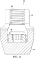
- FIGS. 11 and 12 are partial cross-sectional views of FIGS. 9 and 10 respectively and are provided for descriptive detail with respect to the various structure and features described above. For conciseness all the descriptive detail is not repeated, but the FIGS. can be understood by the description above and the various numbered call-outs of FIGS. 11 and 12 .
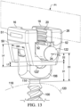
- FIG. 13 there is shown another example of a tulip head extender 10 that, when installed onto tulip head 106, can facilitate the repositioning of rod 122 with respect to bone surface 120 from a distance having a dimension D1 to an additional distance having a dimension D2, for a total distance having a dimension D3.
- extender 10 permits the vertical repositioning of rod 122 from an original position shown as 122 without disturbing the original position of pedicle screw 100.
- the dimension D2 can be predetermined by varying the geometry of extender 10, as will be more fully understood in light of the description below.
- the example embodiment of extender 10 shown in FIG. 13 can have a rod securing body portion 50 having two opposing arms 16, 18, each including a portion of first interior threads 20.
- First and second opposing arms can extend upwardly from a curved lower surface defining a substantially U-shaped interior channel 22 that can have a first channel axis 24.
- First arm 16 and second arm 18 can be described as being opposed across a first imaginary plane P1 parallel to first channel axis 24 and bisecting the securing body portion 50, and, when in use also bisecting tulip head 106 in a like manner.
- Extender 10 can have generally parallel spaced apart first and second U-shaped sides, 26 and 28.
- First and second U-shaped sides can be substantially identical in size and shape and have a separation width SW having a dimension sized according to the size of the tulip head 106 of the pedicle screw 100 over which extender 10 can be lowered and set, somewhat in saddle fashion.
- First and second sides 26 and 28 (opposite side of side 26) can each have an externally facing surface that is generally planar and perpendicular to the imaginary plane P1.
- First and second sides 26 and 28 need not be U-shaped, but can have any shape constrained only by general design and function considerations.
- first and second sides 26 and 28 can have rectangular shape, for example, and remain functionally capable of being saddled over the tulip head 106 of pedicle screw 100.
- first interior threads 20 of first and second arms can be complementary to receive an appropriately sized set screw (not shown).
- first and second arms 16 and 18, first interior threads 20, and interior channel 22 correspond to the same or similar functional features of a tulip head, such as tulip head 106 of pedicle screw 100.
- the features of the rod securing body 50 of extender 10 can include any features 51 desired or required on illustrative bone anchors such as, for example, pockets, tabs, indentations, and openings, to engage with a variety of instruments such as, for example, a particular rod reducing tool, and, as such, facilitate rod reduction as known, albeit reducing the rod a shorter distance than what would have been required to reduce it to the original rod seat as shown in FIG. 13 .
- Rod securing body 50 can be secured to tulip head 106 in any suitable manner, for example, by securing to mating engagement portions.
- rod securing body 50 can have tabs that can engage pockets 114 of tulip head 106.
- tabs of rod securing body can be flexibly resilient, and can be separated apart while rod securing body is pressed down onto tulip head 106 and snapped inwardly when tabs engage pockets 114.
- a first set screw can be, optionally, threadingly engaged to the internal extender threads 20 and threaded through the extender until it threadingly engages the internal threads 116 of tulip head 106.
- the first set screw can be threaded into the tulip head to the desired position to secure and/or hold a spinal fixation rod 122 in position within the extender channel between the curved surface of the channel 22 and the first set screw, and at the same time, to hold and/or secure the extender 50 to tulip head 106.
- a second extender set screw e.g., extender set screw 36
- Rod securing body 50 can have generally flat, inwardly extending surfaces 52 that can abut the top surface of tulip head 106 when rod securing body is positioned for receiving a rod.
- Interior channel 22 can have a lower surface a distance having a dimension L3 above the lower surface of the extender 10.
- Inwardly extending surfaces 52 can be disposed at a forth distance having a dimension L4 above the lower surface of extender 10.
- extender 10 is secured to tulip head 106 by placing over the tulip head 106 in a saddle-like fashion, first and second arms 16 and 18, first interior threads 20, and interior channel 22 effectively define a second tulip head into which a rod 122 can be reduced.
- the dimension D2 above which a rod would be reduced into tulip head 106 of pedicle screw 100 can be predetermined by adjusting by design the various described components and dimensions.
- a doctor or other operator can choose an extender 10 having dimensions, including dimensions L3 and L4 for the particular pedicle screw 100 being utilized, and the desired dimension D3 for elevated rod reduction.
- extender 10 provides great flexibility to increase the rod reduction height relative to bone surface 120 for a fixed position of a tulip head 106 of a fixed pedicle screw 100.
- extender 10 can be attached to the tulip head 106 of a pedicle screw 100 to increase the distance from bone surface 120 from a first distance having a dimension D1 to a third distance having a dimension D3, which is greater than D 1 .
- first and second arms 16 and 18, first interior threads 20, and interior channel 22 effectively define a second tulip head into which a rod 122 can be reduced.
- the second dimension D2 above which a rod would be reduced into tulip head 106 of pedicle screw 100 can be predetermined by adjusting by design the various described components and dimensions.
- extender 10 having dimensions, including dimensions L3 and L4 for the particular pedicle screw 100 being utilized, and the desired dimension D3 for rod reduction.
- extender 10 provides great flexibility to increase the rod reduction height relative to bone surface 120 for a fixed position of a tulip head 106 of a fixed pedicle screw 100.
- FIGS. 14-21 there is shown another example of a tulip head extender 10 that, when installed onto tulip head 106, can facilitate the repositioning of rod 122 with respect to bone surface 120 from a distance having a dimension D1 to an additional distance having a dimension D2, for a total distance having a dimension D3 (as depicted in FIG. 18 ).
- extender 10 permits the vertical repositioning of rod 122 without disturbing the original position of a pedicle screw 100.
- the dimension D2 can be predetermined by varying the geometry of extender 10, as will be more fully understood in light of the description below.
- extender 10 can comprise three discrete parts that together serve to fix a spinal fixation rod 122 on a pedicle screw head 106 at an elevated distance from the bone in which pedicle screw is affixed.
- FIG. 14 shows a perspective view of an extender 10 comprising three discrete parts, namely a saddle 70, a cap 72, and a set screw 74, which can be in all respects identical to the set screw 36 described above. All three parts can be made of any suitable material, including injection molded polymer materials.
- saddle 70 can be disposed within the tulip head 106 of a pedicle screw (i.e., within channel 107). Saddle 70 can be slid into the tulip head 106 and can rest on the rod seat 108. Saddle 70 can have on the upper, rod-facing side a surface that defines an elevated rod seat 108. Saddle 70 is described in more detail with respect to FIG. 19 .
- a cap 72 can be snapped onto tulip head 106, for example, by utilizing tabs 74 that can clip onto pockets 114 of tulip head 106.
- One tab 74 can be hooked into one pocket 114, and the cap 72 can be rotated and pressed such that the other tab 74 can be hooked, or snapped, into the opposite pocket 114.
- the tabs 74 can be fabricated from a material and/or by design such that one or more of the tabs 74 can flex outward to go over and/or about the outer circumference of the tulip head and then snap back into its normal position into one or more of the pockets 114.
- a spinal fixation rod 122 may be positioned into the saddle prior to the cap 73 being positioned upon and secured to the tulip head, thus positioning the rod 122 between the saddle and the cap.
- the set screw 36 may be threadingly engaged to the tulip head 106 and/or the cap 72.
- a spinal fixation rod 122 can be positioned between them, and secured to the tulip head 106 by inserting and securing a set screw 36, as shown in FIG. 14 (i.e., threadingly engaged to the tulip head 106 and/or the cap 72).
- FIG. 18 A schematic perspective view of the extender 10 shown in FIGS. 14-17 is depicted in FIG. 18 .
- extender 10 as described with reference to FIGS. 14-16 , is secured to a pedicle screw head 106 having a rod seat 108 at an elevation D1 above the bone surface, the elevated rod seat 108' can be elevated above the rod seat 108 by a distance having a dimension D2 which can be predetermined by adjusting by design the various described components and dimensions.
- a doctor or other operator can choose an saddle 70 having dimensions, specifically a saddle height dimension as discussed below, for the particular pedicle screw 100 being utilized, and the desired dimension D3 for elevated rod reduction.
- extender 10 provides great flexibility to increase the rod reduction height relative to bone surface 120 for a fixed position of a tulip head 106 of a fixed pedicle screw 100.
- FIG. 19 shows a perspective view of a representative saddle 70 used in the extender 10 shown in FIGS. 14-17 .
- saddle 70 can be generally H-shaped having a longitudinally extending curved surface 80 that serves as the elevated rod seat 108.
- a pair of opposing guide tabs 82 can be disposed at each longitudinal end of the curved surface 80.
- the size and spacing of tabs 82 can be predetermined according to the dimensions of the tulip head 106 onto which saddle 70 is placed.
- Saddle 70 can have a thickness from a bottom surface to a top surface of the elevated rod seat 108' SH, as shown in FIG. 19 .
- the saddle height SH can be predetermined for the desired dimension D3 for elevated rod reduction.
- Cap 72 can have two opposed tabs 74 that can have a general hook-shape such that a first tab 74' with a hook feature 84' that can engage with a pocket 114 of tulip head 106, as illustrated above with respect to FIG. 16 .
- a second tab 74" with a second hook feature 84" can be pressed down and snapped into a pocket 114 on the opposite side of a tulip head 106.
- a stress relief feature 86 which can include a slot 88 and/or a slit 90 on the upper portion of cap 72, from which tabs 74 extend downwardly, can be included on cap 72.
- Cap 72 can also have indented features, such as a pocket 114' on opposite side surfaces of cap 72. Pockets 114' provide a connection for connectivity and operation of known instruments such as, for example, a driving tool and/or rod reducing tool.
- Set screw 36 having external threads that engage with the internal threads of the tulip head of a pedicle screw, or other internal threads of extenders 10 as described herein.
- Set screw 36 can be turned by a tool that can be inserted into a driving portion 44 that can be a socket into which a driving tool can be inserted and securely rotated to rotate set screw 36.
- FIGS. 22-25 there is illustrated further examples of extenders 10 that facilitate positioning of a spinal fixation rod 122 both laterally and upwardly with respect to a fixed pedicle screw 100 tulip head 106.
- FIGS. 22 and 23 illustrate an extender 10 that facilitates laterally elevated in-line positioning of rod 22.
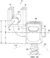
- FIGS. 24 and 25 illustrate an extender 10 that facilitates laterally elevated cross positioning of rod 22.
- extender 10 that permits a rod 122 to be reduced to an elevation greater than the elevation dictated by a pedicle screw 100 fixed in a bone 118.
- extender 10 can be a unitary construction, and can have a mounting bar 60 that can be cylindrical, and can be sized to fit and be secured into tulip head 106 of fixed pedicle screw 100. Securement of mounting bar 60 into tulip head 106 can be, for example, by a set screw (not shown) tightened into internal threads 116 of tulip head 106.
- Mounting bar can have any cross section, but can be a cylindrical shape having a central axis 62.
- Extender 10 as illustrated in FIGS. 22 and 23 can have disposed on an upturned end of mounting bar 60 an extender tulip head 64 that can be in size, shape, and function, substantially identical to tulip head 106 of pedicle screw 100.
- extender tulip head 64 can have two opposing arms 16, 18, each including a portion of interior threads 20.
- First arm 16 and second arm 18 can extend from a curved lower surface defining a substantially U-shaped interior channel 22 that can have a first channel axis 24 can be coincident with the central axis of rod 122 and can be generally parallel to and in the same plane as central axis 62.
- the first interior threads 20 of first and second arms can be complementary to receive an appropriately sized set screw (not shown).
- first and second arms 16 and 18, first interior threads 20, and interior channel 22 correspond to the functional features of a tulip head, such as tulip head 106 of pedicle screw 100.
- the features of the extender tulip head 64 can include any features required (but not shown) to engage with a particular rod reducing tool, and, as such, facilitate rod reduction as known, albeit reducing the rod to distance having a dimension D3 rather than distance a lesser dimension D1, as shown in FIG. 22 .
- the first channel axis 24 and the central rod axis 62 of mounting bar 60 are parallel and in the same plane, and thus a fixation rod 122 reduced into extender tulip head 64 is "in line" with the mounting bar 60, and thus in line directionally with where the fixation rod 122 would have been mounted in the tulip head 106 of pedicle screw 100.
- FIGS. 24 and 25 an example of another extender 10 that facilitates fixation of a rod 122 both laterally and upwardly with respect to a fixed pedicle screw 100 tulip head 106 is shown.
- the extender of FIGS. 24 and 25 is identical in most respects to that shown in FIGS. 22 and 23 , with the material difference being that extender tulip head 64 has a different orientation, such that a rod 122 reduced into it would not be "in line" with mounting bar, but be at some angle to it, albeit remaining elevated by distance having a dimension D2 with respect to the mounting bar.
- first arm 16 and second arm 18 can extend from a curved lower surface defining a substantially U-shaped interior channel 22 that can have a first channel axis 24 that is generally parallel to but in different plane than central axis 62.
- first channel axis 24 can be in a plane that is substantially perpendicular to a plane in which central axis 62 resides.
- the first interior threads 20 of first and second arms can be complementary to receive an appropriately sized set screw (not shown).
- first and second arms 16 and 18, first interior threads 20, and interior channel 22 correspond to the functional features of a tulip head, such as tulip head 106 of pedicle screw 100.
- the features of the extender tulip head 64 can include any features required (but not shown) to engage with a particular rod reducing tool, and, as such, facilitate rod reduction as known, albeit reducing the rod to distance to a dimension D3 rather than to a distance having a dimension D1 which is less than D3, as shown in FIG. 24 .
- dimension D3 can be varied depending on the dimensions of extender 10, specifically the distance which can be measured from mounting bar axis 62 and a lower surface 66 of head 64, which distance can be the dimension L5. More particularly, dimension D3 can be varied depending on the distance which can be measured from mounting bar axis 62 and a rod seating surface 22 of head 64, which distance can be the dimension L6.
- extenders 10 disclosed herein can provide a benefit in the installation and use of spinal fixation rods.
- a method of use of extender 10 includes affixing an extender 10 to an installed tulip head of a pedicle screw, thereby extending, with respect to the pedicle bone, the distance from the pedicle bone that a spinal fixation rod will seat.
- an extender 10 can safely span a gap between the distance from the pedicle bone of the rod seat 108 of a tulip head 106 of an installed pedicle screw and the distance that is determined as safely seating a spinal fixation rod.
- the extender 10 can have a set screw, e.g., set screw 36 of FIGS. 8 and 10 , threaded through the extender 10 and threaded onto the internal threads 116 of the tulip head 106, thereby securing the extender 10 to the tulip head 106.
- a spinal fixation rod 122 can be seated in the extender and secured, e.g., with another set screw threaded into first interior threads 20 as depicted in FIG. 5 .
- the saddle 70 provides for the extended distance with respect to the pedicle bone, i.e., the distance from the pedicle bone that a spinal fixation rod will seat.
- the cap 72 can then be snapped over the top of the tulip head into the slots on the side thereof.
- a set screw can then be tightened down, thereby pulling the cap 72 upward on the slots locking it in place.
- the apparatuses and methods disclosed herein may be used and/or applied in any regions of the spine such as for example, cervical, thoracic, lumbar, sacral, or coccygeal regions.
- the apparatuses and methods disclosed herein may be used and/or applied in severely curved regions of the spine, for example, the lumbar region of the spine, i.e., for a spinal fixation rod secured to any or all of Ll-L5 vertebrae.
- the lumbar region can often exhibit extreme lumbar curves where a spinal fixation rod would necessarily need to be significantly deformed, thus creating large stresses in the rod and/or the pedicle screw and/or the bone, as well as possible fracture of either the rod, screw, or bone.
- Extenders 10 can also be used in other vertebrae, including, for example, in the upper thoracic region for severe kyphosis, i.e., for a spinal fixation rod secured to any or all of T1 -T12 vertebrae, where there can also be significantly rod stresses present. Extenders 10 can also be used in vertebrae of the cervical region, i.e., for a spinal fixation rod secured to any or all of C1-C7.
- a method of use can include the following steps: inserting a pedicle screw having a tulip head in a vertebral bone to a predetermined distance; placing a spinal fixation rod in close proximity to, e.g., hovering over, the tulip head of the inserted pedicle screw; determining that the distance the spinal fixation rod must be reduced into the tulip head is too great to allow for safe reduction of the spinal fixation rod into the tulip head, e.g., because of the likelihood of excessive stress on the pedicle bone; securing an extender 10 to the tulip head of the pedicle screw; seating the spinal fixation rod into the extender 10; and securing the spinal fixation rod into the extender 10.
- a method of use for extenders as described above can be described as a method for securing a spinal fixation rod to a pedicle bone, the method including the following steps: providing a tulip head of a pedicle screw; providing a spinal fixation rod; securing an extender 10 to the tulip head of the pedicle screw; seating the spinal fixation rod into the extender 10; and securing the spinal fixation rod into the extender 10.
- a method of use for extenders as described above can be described as a method for securing a spinal fixation rod to a pedicle bone, the method including the following steps: providing a tulip head of a pedicle screw screwed into a pedicle bone; providing a spinal fixation rod; securing an extender 10 to the tulip head of the pedicle screw; seating the spinal fixation rod into the extender 10; and securing the spinal fixation rod into the extender 10.
- a method of use for extenders as described above can be described as a method for securing a spinal fixation rod to a pedicle bone, the method including the following steps: providing a plurality of pedicle screws each comprising a tulip head, and each screwed into a respective pedicle bone; securing at least one extender 10 to the tulip head of at least one of the tulip heads of at least one of the pedicle screws; bending a spinal fixation rod to an approximate shape; seating the bent spinal fixation rod into the at least one extender 10; and securing the spinal fixation rod into the at least one extender 10.
- a method of use for extenders as described above can be described as a method for securing a spinal fixation rod to a pedicle bone, the method including the following steps: providing a plurality of pedicle screws each comprising a tulip head, and each screwed into a respective pedicle bone; recognizing that the required shape of an attached spinal fixation rod will exert excessive stress on the pedicle bone; securing at least one extender 10 to the tulip head of at least one of the tulip heads of at least one of the plurality of pedicle screws; bending a spinal fixation rod to an approximate shape; seating the bent spinal fixation rod into the at least one extender 10; and securing the spinal fixation rod into the at least one extender 10.
- a method of use for extenders as described above can be described as a method for securing a spinal fixation rod to a pedicle bone, the method including the following steps: on the spine of a patient in need of orthopedic surgery, providing a plurality of pedicle screws each comprising a tulip head, and each screwed into a respective pedicle bone of the spine; recognizing that the required shape of an attached spinal fixation rod exerts excessive stress on the pedicle bone; securing at least one extender 10 to at least one of the tulip heads of at least one of the plurality of pedicle screws; bending a spinal fixation rod to an approximate shape; seating the bent spinal fixation rod into the at least one extender 10; and securing the spinal fixation rod into the at least one extender 10.
- a method of use for extenders as described above can be described as a method for securing a spinal fixation rod to a pedicle bone, the method including the following steps: on the lumbar region of a spine of a patient in need of orthopedic surgery, providing a plurality of pedicle screws each comprising a tulip head, and each screwed into a respective pedicle bone of the spine selected from the group consisting of L1-L5; recognizing that the required shape of an attached spinal fixation rod exerts excessive stress on the pedicle bone or the pedicle screw; securing at least one extender 10 to at least one of the tulip heads of at least one of the plurality of pedicle screws; bending a spinal fixation rod to an approximate shape; seating the bent spinal fixation rod into the at least one extender 10; and securing the spinal fixation rod into the at least one extender 10 in the lumbar region of the spine.
- a method of use for extenders as described above can be described as a method for securing a spinal fixation rod to a pedicle bone, the method including the following steps: on the cervical region of a spine of a patient in need of orthopedic surgery, providing a plurality of pedicle screws each comprising a tulip head, and each screwed into a respective pedicle bone of the spine selected from the group consisting of C 1 -C7; recognizing that the required shape of an attached spinal fixation rod exerts excessive stress on the pedicle bone or the pedicle screw; securing at least one extender 10 to at least one of the tulip heads of at least one of the plurality of pedicle screws; bending a spinal fixation rod to an approximate shape; seating the bent spinal fixation rod into the at least one extender 10; and securing the spinal fixation rod into the at least one extender 10 in the cervical region of the spine.
- a method of use for extenders as described above can be described as a method for securing a spinal fixation rod to a pedicle bone, the method including the following steps: on the thoracic region of a spine of a patient in need of orthopedic surgery, providing a plurality of pedicle screws each comprising a tulip head, and each screwed into a respective pedicle bone of the spine selected from the group consisting of T 1 -T12; recognizing that the required shape of an attached spinal fixation rod exerts excessive stress on the pedicle bone or the pedicle screw; securing at least one extender 10 to at least one of the tulip heads of at least one of the plurality of pedicle screws; bending a spinal fixation rod to an approximate shape; seating the bent spinal fixation rod into the at least one extender 10; and securing the spinal fixation rod into the at least one extender 10 in the thoracic region of the spine.
- a method of use for extenders as described above can be described as a method for repositioning and securing a spinal fixation rod to a pedicle bone, the method including the following steps: on the lumbar region of a spine of a patient in need of orthopedic surgery, providing a plurality of pedicle screws, each of the pedicle screws comprising a tulip head, and each screwed into a respective pedicle bone of the spine selected from the group consisting of L1-L5; seating a spinal fixation rod into a portion of the tulip heads; recognizing that the required shape of the spinal fixation rod exerts, or will exert, excessive stress on the pedicle bone or the pedicle screw; removing the spinal fixation rod from the portion of the tulip heads; securing at least one extender 10 to at least one of the tulip heads of at least one of the plurality of pedicle screws; re-seating the spinal fixation rod to into the portion of tulip heads, including the at
- the shape of the relevant portion of the spinal fixation rod 122 i.e., at and near the extender 10 can be characterized as wherein the radius of curvature of the bend in the spinal fixation rod is greater when used with an extender 10 relative to the radius of curvature necessary without the use of an extender 10.
- a method of use for extenders as described above can be described as a method for repositioning and securing a spinal fixation rod to a pedicle bone, the method including the following steps: on the cervical region of a spine of a patient in need of orthopedic surgery, providing a plurality of pedicle screws, each of the pedicle screws comprising a tulip head, and each screwed into a respective pedicle bone of the spine selected from the group consisting of Cl-C7; seating a spinal fixation rod into a portion of the tulip heads; recognizing that the required shape of the spinal fixation rod exerts, or will exert, excessive stress on the pedicle bone or the pedicle screw; removing the spinal fixation rod from the portion of the tulip heads; securing at least one extender 10 to at least one of the tulip heads of at least one of the plurality of pedicle screws; re-seating the spinal fixation rod to into the portion of tulip heads, including the at least one extend
- the shape of the relevant portion of the spinal fixation rod 122 i.e., at and near the extender 10 can be characterized as wherein the radius of curvature of the bend in the spinal fixation rod is greater when used with an extender 10 relative to the radius of curvature necessary without the use of an extender 10.
- a method of use for extenders as described above can be described as a method for repositioning and securing a spinal fixation rod to a pedicle bone, the method including the following steps: on the thoracic region of a spine of a patient in need of orthopedic surgery, providing a plurality of pedicle screws, each of the pedicle screws comprising a tulip head, and each screwed into a respective pedicle bone of the spine selected from the group consisting of T1-T12; seating a spinal fixation rod into a portion of the tulip heads; recognizing that the required shape of the spinal fixation rod exerts, or will exert, excessive stress on the pedicle bone or the pedicle screw; removing the spinal fixation rod from the portion of the tulip heads; securing at least one extender 10 to at least one of the tulip heads of at least one of the plurality of pedicle screws; re-seating the spinal fixation rod to into the portion of tulip heads, including the
- the shape of the relevant portion of the spinal fixation rod 122 i.e., the at and near the extender 10 can be characterized as wherein the radius of curvature of the bend in the spinal fixation rod is greater when used with an extender 10 relative to the radius of curvature necessary without the use of an extender 10.
- a non-claimed method for securing a spinal fixation rod to a pedicle bone in the lumbar region of a spine of a patient in need of orthopedic surgery to modify the curvature of the lumbar region including the following steps: providing a plurality of pedicle screws, at least one of the pedicle screws comprising a tulip head, and each screwed into a respective pedicle of a vertebrae of the spine selected from the group consisting of L1-L5; providing a pedicle screw extender; reducing a spinal fixation rod at least partially into the tulip head; recognizing that upon full reduction and securing of the spinal fixation rod into the tulip head the spinal fixation rod will exert excessive stress on the respective vertebra; removing the spinal fixation rod from the tulip head; securing the pedicle screw extender to the tulip head; re-reducing the spinal fixation rod into the pedicle screw extender; and securing the spinal fixation rod into the pedicle
- a non-claimed method for securing a spinal fixation rod to a pedicle bone of a spine of a patient in need of orthopedic surgery to modify the curvature of the spine including the following steps: providing a tulip head of a pedicle screw; providing a pedicle screw extender; providing a spinal fixation rod; securing the pedicle screw extender to the tulip head of the pedicle screw; seating the spinal fixation rod into the pedicle screw extender; and securing the spinal fixation rod into the pedicle screw extender.
- a non-claimed method for securing a spinal fixation rod to a pedicle bone on the lumbar region of a spine of a patient in need of orthopedic surgery to modify the curvature of the lumbar region including the following steps: providing a pedicle screw comprising a tulip head, the pedicle screw being screwed into a pedicle bone of a vertebrae of the spine selected from the group consisting of L1-L5; providing a pedicle screw extender; recognizing that the required shape of an attached spinal fixation rod exerts excessive stress on the pedicle bone; securing the pedicle screw extender to the tulip head of the pedicle screw; bending a spinal fixation rod to an approximate desired curvature of the lumbar region; seating the spinal fixation rod into the pedicle screw extender; and securing the spinal fixation rod into the pedicle screw extender.
- the pedicle screw extender comprises: an upper body portion joined to a lower body portion, the upper body portion having two opposing arms extending upwardly from a curved lower surface to define a substantially U-shaped interior channel having a first channel axis, the curved lower surface defining an access opening extending through the upper body portion in a direction generally perpendicular to the first channel axis, the lower body portion extending downwardly as a protrusion from the upper body portion and joined to the upper body portion and having first and second sides, the first and second sides being substantially planar and parallel and separated by an interior portion, the first and second sides defining a protrusion height and a protrusion width, and a screw disposed in the interior portion and having external threads defining a thread diameter greater than the protrusion width.
Landscapes
- Health & Medical Sciences (AREA)
- Orthopedic Medicine & Surgery (AREA)
- Life Sciences & Earth Sciences (AREA)
- Surgery (AREA)
- Neurology (AREA)
- Heart & Thoracic Surgery (AREA)
- Engineering & Computer Science (AREA)
- Biomedical Technology (AREA)
- Nuclear Medicine, Radiotherapy & Molecular Imaging (AREA)
- Medical Informatics (AREA)
- Molecular Biology (AREA)
- Animal Behavior & Ethology (AREA)
- General Health & Medical Sciences (AREA)
- Public Health (AREA)
- Veterinary Medicine (AREA)
- Surgical Instruments (AREA)
Description
- This application claims the priority benefit of
U.S. Provisional Patent App. No. 62/778,663 filed December 12, 2018 - Spinal fixation systems may be used to surgically fix, adjust, and/or align the spinal column. One type of spinal fixation system employs a spinal rod for supporting the spine and fixing, adjusting, and/or aligning all or portions of the spinal column into a desired orientation. Attachment of the spinal rod to the spinal column has been achieved using a variety of vertebral anchors. Pedicle screws have been used successfully as vertebral anchors. Pedicle screws and connectors in combination with spinal rods can align and correct deformities in the natural spinal alignment as well as repair traumatic injury. In general, a pedicle screw has a head with a receiving opening into which a spinal rod can be secured. From
US 2011/0106178 A1 , a head extender for use with a pedicle screw to ease connection to a spinal rod is known. The pedicle screw head extenders provided inUS 2011/0106178 A1 can be used with either fixed head pedicle screws or multi-axial head pedicle screws. The pedicle screw head extenders can either be threaded to or snapped into place within the various pedicle screws. It may also be possible to use the present invention with other types of spinal screws that may be connected to spinal rods without the screw actually being implanted through the pedicle of the spine. Further examples of head extenders for use with pedicle screws are disclosed byUS 2010/0160981 A1 ,US 2018/0317972 A1 andUS 2014/0135839 A1 . - However, once a pedicle screw is set, i.e., screwed into a portion of the pedicle bone, the location of a spinal rod to be set into it is also set due to the fixed position of the head of the pedicle screw. It can be the case that during the process of spinal fixation it is discovered that the fixed location of the head of the pedicle screw, and, therefore, the fixed location of the reduced spinal rod, is not ideal.
- Accordingly, there remains an unmet need for an apparatus, system, and method to provide for variable positioning of a spinal rod in a fixed pedicle screw.
- Further, there remains an unmet need for spinal fixation apparatus that permits greater flexibility for neuromuscular and revision cases by providing for a greater variety of instrumentation.
- The present invention provides a pedicle screw tulip head extender according to
claim 1. - Preferred embodiments are set forth in the dependent claims.
- Associated surgical methods are also described herein to aid understanding the invention. These methods do not form part of the claimed invention.
- The present disclosure will be more readily understood from a detailed description of some embodiments taken in conjunction with the following figures.
- The embodiments which form part of the invention are illustrated in the
figures 4-12 . - The examples shown in the other figures do not form part of the invention but represent background art that is useful for understanding the invention.
-
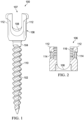
FIG. 1 depicts a side elevation view of an example of a pedicle screw. -
FIG. 2 depicts a partial cross-sectional view of a head of the pedicle screw ofFIG. 1 . -
FIG. 3 depicts a schematic representation of a pedicle screw in a bone. -
FIG. 4 depicts a perspective view of one embodiment of a pedicle screw extender of the present invention engaged with a pedicle screw. -
FIG. 5 depicts a perspective view of the pedicle screw extender ofFIG. 4 . -
FIG. 6 depicts a perspective view of one example of a pedicle screw extender of the present disclosure. -
FIG. 7 depicts a perspective view of the pedicle screw extender ofFIG. 6 . -
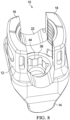
FIG. 8 depicts a top perspective view of the pedicle screw extender ofFIG. 6 . -
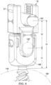
FIG. 9 depicts a side elevation view of the pedicle screw extender ofFIG. 6 . -
FIG. 10 depicts a side elevation view of the pedicle screw extender ofFIG. 6 . -
FIG. 11 depicts a partial cross-sectional view of Section 11-11 ofFIG. 9 . -
FIG. 12 depicts a partial cross-sectional view of Section 12-12 ofFIG. 10 . -
FIG. 13 depicts a perspective view of one example of a pedicle screw extender of the present disclosure. -
FIG. 14 depicts a perspective view of one example of a pedicle screw extender of the present disclosure engaged to head of a pedicle screw. -
FIG. 15 depicts a perspective view of a portion of the pedicle screw extender ofFIG. 14 . -
FIG. 16 depicts a perspective view of the pedicle screw extender ofFIG. 14 partially engaged with a head of a pedicle screw. -
FIG. 17 depicts a perspective view of a portion of the pedicle screw extender ofFIG. 14 engaged with a head of a pedicle screw. -
FIG. 18 depicts a schematic perspective view of the pedicle screw extender ofFIG. 14 engaged with a head of a pedicle screw. -
FIG. 19 depicts a perspective view of a portion of the pedicle screw extender ofFIG. 14 . -
FIG. 20 depicts a perspective view of a portion of the pedicle screw extender ofFIG. 14 . -
FIG. 21 depicts a perspective view of a portion of the pedicle screw extender ofFIG. 14 . -
FIG. 22 depicts a perspective view of one example of a pedicle screw extender of the present disclosure. -
FIG. 23 depicts a perspective view of one example of a pedicle screw extender of the present disclosure. -
FIG. 24 depicts a perspective view of one example of a pedicle screw extender of the present disclosure. -
FIG. 25 depicts a perspective view of one example of a pedicle screw extender of the present disclosure. - Various non-limiting embodiments of the present disclosure will now be described to provide an overall understanding of the principles of the structure, function, and use of the apparatuses, systems, methods, and processes disclosed herein. One or more examples of these non-limiting embodiments are illustrated in the accompanying drawings.
- Described herein are embodiments of bone anchors (e.g., hooks, screws, etc.) useful for orthopedic procedures such as, for example, spinal fixation. In the illustrated embodiments a pedicle screw is disclosed to teach the features of a bone anchor and how the one or more embodiments of tulip head extenders engage and/or work with such illustrative pedicle screws., but the disclosure is not to be limited only to pedicle screws, nor are the tulip head extenders limited to engaging and/or working with only pedicle screws.
- Referring to
FIG. 1 , arepresentative pedicle screw 100 is shown. Pediclescrew 100 can be any of known pedicle screws with any of known beneficial features for installation and use in processes and systems such as, for example, of spinal fixation. For the purposes of the present disclosure, the pedicle screw is described as including ascrew shank 102, aneck 104, ahead 106, which is often referred to as atulip head 106. Thetulip head 106 can include first andsecond tulip arms 112 opposed from each other. First and second tulip arms form achannel 107. First andsecond tulip arms 112 can extend from a curved lower surface (e.g., rod seat 108) defining the substantially U-shapedinterior channel 107. Thechannel 107 can be constructed to receive a spinal fixation rod (e.g., 122) and can include a channel axis. The channel axis can correspond to, and be coincident with, a longitudinal axis of a spinal fixation rod when it is reduced into thechannel 107. - The shank can have an inner diameter and an outer diameter, the inner diameter and outer diameter each being determined by the size of the screw and the depth of
threads 110 onshank 102. The thread depth, pitch, and other dimensional features can be predetermined based on the requirements of the pedicle screw, as is known in the art. That is, the proportions of the pedicle screw depicted are for illustrative purposes only and variations in the length, shape, and/or configuration of such pedicle screw may vary such as, for example, the shape and size of the head, the length of the shank, diameter of the screw, thread pitch, thread length, number of thread leads, shank induced compression and the like may be varied without departing from the scope of the disclosure. - Other components and features of a pedicle screw may be included that aid in its insertion into a bone and its use. For example, as depicted in the partial cross-sectional view of
tulip head 106 inFIG. 2 ,tulip head 106 may include features for compatible operation with driving tool (not shown) and a rod reduction device (not shown). As a specific example, a rod reduction device, as is known in the art, may be used to engage withtulip head 106 to urge, or reduce, a spinal fixation rod into thechannel 107 and toward therod seat 108, manipulate one or more vertebrae, and/or insert a set screw for temporary or stationary fixation of the spinal rod into the pediclescrew tulip head 106. For this reason,tulip head 106 can have various features, such as grasping tabs and/orpockets 114, for connectivity and operation of the driving tool, rod reducing tool, and/or other instruments, andinternal threads 116 for receiving a set screw or other implants and/or instruments. - Referring now to
FIG. 3 , there is shown apedicle screw 100 screwed into abone 118, the surface of which is representatively depicted by the dashedline 120.Bone 118 can be a pedicle, andpedicle screw 100 can be driven into the pedicle until theneck 104 is adjacent thebone 118. In an embodiment, the pedicle can be undertapped for the appropriate screw size. After the pedicle is undertapped a flexible feeler probe may be used to verify presence of threads in the tapped hole. To measure the length of the hole, a feeler probe is advanced to the floor of the hole and a hemostat is clamped to the feeler probe at the point where it exits the pedicle. The appropriate screw diameter and length may subsequently be selected based on both preoperative measurement and intraoperative observation. The same technique can be repeated for any remaining pedicles that need to be inserted and/or instrumented. - A rod reduction tool can be applied over the
tulip head 106 of the screw. In an embodiment, fingers of the rod reduction device can engage thepockets 114 of the pediclescrew tulip head 106. Therod 122 can then be reduced by the rod reduction device to set inrod seat 108. A set screw driver can then be used to introduce aset screw 124. The set screw can be passed through the rod reduction device and rotated until it bottoms out, securingrod 122 into thetulip head 106. - As depicted in
FIG. 3 , oncerod 122 is reduced intotulip head 106 and setscrew 124 is set, the distance D1 frombone surface 120 and theaxial center 126 ofrod 122 is immovably fixed. As illustrated, the distance D1 is shown as extending to the axial center of therod 122, but for description purposes the dimensions D1, as well as D2 and D3 described below, can be measured to the top or bottom of the rod without departing from the scope of the disclosure. - Referring to
FIG. 4 there is shown an embodiment of a pedicle screwtulip head extender 10 that, when engaged to and/or installed intotulip head 106, can facilitate the repositioning ofrod 122 with respect tobone surface 120 from a distance D1 an additional distance D2, for a total distance D3. As can be understood,extender 10 permits the vertical repositioning ofrod 122 from an original position shown as 122' without disturbingpedicle screw 100. The distance D2 can be predetermined by varying the geometry ofextender 10, as will be more fully understood in light of the description below. - An embodiment of pedicle screw
tulip head extender 10 as shown inFIG. 4 is depicted in more detail inFIG. 5 . In the illustrated embodiments, terms such as "vertical," "upper," "lower" "upwardly," and "downwardly" are used in relation to theextender 10 in the orientation shown in the FIGS, and corresponding to the orientation generally experienced in use of pedicle screws and related instrumentation.Extender 10 has anupper body portion 12 joined to alower body portion 14. Theupper body portion 12 can be integrally formed withlower body portion 14, such as by machining from a blank, injection molding, etc., or the two parts can be manufactured separately and joined by adhesive, welding, press fit, or the like.Upper body portion 12 has afirst extender arm 16 and asecond extender arm 18 opposed to the first extender arm.First extender arm 16 andsecond extender arm 18 extend from a curved lower surface defining a substantially U-shapedinterior channel 22 that has afirst channel axis 24. Thefirst channel axis 24 can correspond to, and be coincident with, a longitudinal axis of arod 122 when reduced intoextender 10. The firstinterior threads 20 of first and second extender arms can be complementary to receive an appropriately sized set screw (not shown). As can be understood from the description above, first andsecond extender arms interior threads 20, andinterior channel 22 correspond to the same or similar functional features of a tulip head, such astulip head 106 ofpedicle screw 100. As can be further understood, the features of theupper portion 12 ofextender 10 can include anyfeatures 51 desired or required on illustrative bone anchors such as, for example, pockets, tabs, indentations, and openings, to engage with a variety of instruments such as, for example, a particular rod reducing tool, and, as such, facilitate rod reduction by known techniques, albeit reducing the rod a shorter distance than what would have been required to reduce it to the original rod seat 108 (e.g.,FIGS. 2 and3 ). -
Lower portion 14 extends downwardly from theupper portion 12, and has a portion sized to fit into thechannel 107 and seat on therod surface 108 oftulip head 106 ofpedicle screw 100. That is,lower portion 14 can be a substantially U-shaped protrusion, joined toupper portion 12 by generally parallel spaced apart first and second U-shaped sides, 26 and 28 (side 28 on the side not seen inFIG. 5 ). First and second U-shaped sides can be substantially identical in size and shape and have a protrusion width PW having a dimension sized according to the channel width of thetulip head 106 of thepedicle screw 100. First and second U-shaped sides can be spaced apart a distance defining a protrusion depth PD, the protrusion depth PD being a dimension suitable for stable securement to thetulip head 106 ofpedicle screw 100, and can be predetermined based on the sizing and requirements of related instrumentation. First andsecond sides 26 and 28 need not be U-shaped, but can have any shape constrained only in that thelower portion 14 be able to be insertable into and seat with thetulip head 106 of a pedicle screw 100 (e.g.,channel 107 and seat 108). Thus, first andsecond sides 26 and 28 can have rectangular shape, for example, and remain functionally capable of being seated into thetulip head 106 ofpedicle screw 100. - The
extender 10 can have first andsecond surfaces upper portion 12, and which can abut the top surface oftulip head 106 ofpedicle screw 100 when theextender 10 is set into place. Although in some embodiments, theextender 10 may not have first andsecond surfaces second sides 26 and 28 can extend a distance Ll below and generally perpendicular to first andsecond surfaces rod seat 108 oftulip head 106. Curvedlower surface 22 ofupper portion 12 ofextender 10 can be a distance L2 measured from the bottom of the U-shaped first andsecond sides 26 and 28. Distance L2 can be greater than distance Ll, and can be predetermined by design ofextender 10 based on the desired distance D3, as shown inFIG. 4 . -
Lower portion 14 can have an openinterior portion 34 defined between first and secondU-shaped sides 26 and 28, and in which can be disposed an extender setscrew 36. Openinterior portion 34 can have open access through a pair of opposingwindows 38, 40 (window 40 on the side not seen inFIG. 5 ) through which the extender setscrew 36 may be inserted into and then in its position therein, threads of extender setscrew 36 can extend radially outwardly fromwindows 38, 40. That is, the outside thread diameter of setscrew 36 can be greater than the protrusion width PW. This allows the threads of the extender setscrew 36 to threadingly engage theinner threads 116 of the first andsecond tulip arms 112 when thelower portion 14 is inserted into thetulip channel 107, engaging and/or connecting theextender 10 to thetulip head 100. As can be understood from the description herein, extender setscrew 36 serves functionally similar to theset screw 124 shown inFIG. 3 to set, however, theextender 10 into thetulip head 106 ofpedicle screw 100 as shown inFIG. 4 rather than to set therod 122 into the tulip head as shown inFIG. 3 . - An access opening 42 in
upper portion 12 can extend downwardly through theupper portion 12 in a direction generally perpendicular tofirst channel axis 24.Access opening 42 provides access to the top of extender setscrew 36. Extender setscrew 36 can have on its top surface a driving portion which can engage with a driver to permit rotation of extender setscrew 36 such that its external threads engage theinternal threads 116 oftulip head 106, driving the extender set screw down into thetulip channel 107 and connecting theextender 10 to thepedicle screw 100. - Thus, according to the description above with reference to
FIGS. 4 and5 , it can be understood thatextender 10 can be attached to thetulip head 106 of apedicle screw 100 to increase the distance frombone surface 120 from a distance having a dimension D1 to a distance having a dimension D3, which is greater than Dl. As described, thelower portion 14 ofextender 10 can be positioned between thetulip arms 112 and the threads of extender setscrew 36 can engage theinterior threads 116 oftulip head 106. Extender setscrew 36 can be rotated by a driver extending through access opening 42 ofextender 10 to connect and/orsecure extender 10 totulip head 106. Once extender is secured totulip head 106 by tightening extender setscrew 36, first andsecond extender arms interior threads 20, andinterior channel 22 effectively define a second tulip head into which aspinal fixation rod 122 can be reduced. The distance having a dimension D2 above which a rod would be reduced intotulip head 106 ofpedicle screw 100 can be predetermined by adjusting by design the various described components and dimensions. Thus, in operation, a doctor or other operator can choose anextender 10 having dimensions, including dimensions L1 and L2 for theparticular pedicle screw 100 being utilized, and the distance D3 that the rod is suspended or positioned over the bone and/or the distance the rod is suspended and/or positioned over the installed pedicle screw. As can be understood, therefore,extender 10 provides great flexibility to increase the rod reduction height relative tobone surface 120 for a fixed position of atulip head 106 of a fixedpedicle screw 100. - An embodiment of
tulip head extender 10 similar to that shown inFIG. 4 is depicted in more detail inFIG. 6-12 .FIG. 6 illustrates in a perspective view thatextender 10 can comprise a one-piece molded body, forged and/or machined body, and, as shown inFIG. 7 , a set screw can be disposed internally to theextender 10 body. As an example,extender 10 is molded of any polymer material, and can be injection molded. As described above,extender 10 has anupper body portion 12 joined to alower body portion 14.Upper body portion 12 has two opposingextender arms interior threads 20.First arm 16 andsecond arm 18 can extend from a curved lower surface defining a substantially U-shapedinterior channel 22 that can have afirst channel axis 24. Thefirst channel axis 24 can correspond to, and be coincident with, a longitudinal axis of arod 122 when reduced into extender 10 (not shown). The firstinterior threads 20 of first and second arms can be complementary to receive an appropriatelysized set screw 36, as shown inFIGS. 7-12 . An access opening 42 inupper portion 12 can extend downwardly through theupper portion 12 in a direction generally perpendicular tofirst channel axis 24.Access opening 42 provides access to the top of extender setscrew 36. Extender setscrew 36 can have on its top surface a drivingportion 44 which can be a male or female socket that can engage with a driver to drive rotation of extender setscrew 36. InFIG. 8 , a representative femalesocket driving portion 44 having a generally star-shaped geometry is illustrated. - As can be understood from the description above, first and
second extender arms interior threads 20, andinterior channel 22 correspond to the same or similar functional features of a tulip head, such astulip head 106 ofpedicle screw 100. As can be further understood, the features of theupper portion 12 ofextender 10 can include anyfeatures 51 desired or required on illustrative bone anchors such as, for example, pockets, tabs, indentations, and openings, to engage with a variety of instruments such as, for example, a particular rod reducing tool, and, as such, facilitate rod reduction by known techniques, albeit reducing the rod a shorter distance than what would have been required to reduce it to theoriginal rod seat 108. - As shown in the side elevation views of
FIGS. 9 and10 ,lower portion 14 can extend downwardly from theupper portion 12, and can have a portion sized to fit into thechannel 107 and seat on therod surface 108 oftulip head 106 ofpedicle screw 100. First and second U-shaped sides can be substantially identical in size and shape and have a protrusion width PW having a dimension sized according to the channel width of thetulip head 106 of thepedicle screw 100. First and second U-shaped sides can be spaced apart a distance defining a protrusion depth PD, the protrusion depth PD being a dimension suitable for stable securement to thetulip head 106 ofpedicle screw 100, and can be predetermined based on the sizing and requirements of related instrumentation. First andsecond sides 26 and 28 need not be U-shaped, but can have any shape constrained only in that thelower portion 14 be able to be insertable into and seat with thetulip head 106 of apedicle screw 100. Thus, first andsecond sides 26 and 28 can have rectangular shape, for example, and remain functionally capable of being seated into thetulip head 106 ofpedicle screw 100. - The
extender 10 can have first andsecond surfaces upper portion 12, and which can abut the top surface oftulip head 106 ofpedicle screw 100 when theextender 10 is set into place. First andsecond sides 26 and 28 can extend a distance Ll below and generally perpendicular to first andsecond surfaces FIG. 5 , but for conciseness not shown inFIGS 9-12 , a distance Ll can be substantially equal to the depth of the channel having therod seat 108 oftulip head 106. Curvedlower surface 22 ofupper portion 12 ofextender 10 can be a distance L2 measured from the bottom of the U-shaped first andsecond sides 26 and 28. Distance L2 can be greater than distance Ll, and can be predetermined by design ofextender 10 based on the desired distance D3, as shown inFIG. 4 . -
Lower portion 14 can have an openinterior portion 34 defined between first and secondU-shaped sides 26 and 28, and in which can be disposed an extender setscrew 36. Openinterior portion 34 can have open access through a pair of opposingwindows 38, 40 (window 40 on the side not seen inFIG. 5 ) through which the extender setscrew 36 may be inserted into and then, when in its position therein, threads of extender setscrew 36 can extend radially outwardly from thewindows 38, 40. That is, the outside thread diameter of setscrew 36 can be greater than the protrusion width PW. This allows the threads of the extender setscrew 36 to threadingly engage theinner threads 116 of the first andsecond tulip arms 112 when thelower portion 14 is inserted into thetulip channel 107, engaging and/or connecting theextender 10 to thetulip head 100. As can be understood from the description herein, extender setscrew 36 serves functionally as theset screw 124 shown inFIG. 3 to set, however, theextender 10 into thetulip head 106 ofpedicle screw 100 as shown inFIG. 4 rather than to set therod 122 into the tulip head as shown inFIG. 3 . -
FIGS. 11 and12 are partial cross-sectional views ofFIGS. 9 and10 respectively and are provided for descriptive detail with respect to the various structure and features described above. For conciseness all the descriptive detail is not repeated, but the FIGS. can be understood by the description above and the various numbered call-outs ofFIGS. 11 and12 . - Referring now to
FIG. 13 there is shown another example of atulip head extender 10 that, when installed ontotulip head 106, can facilitate the repositioning ofrod 122 with respect tobone surface 120 from a distance having a dimension D1 to an additional distance having a dimension D2, for a total distance having a dimension D3. As can be understood,extender 10 permits the vertical repositioning ofrod 122 from an original position shown as 122 without disturbing the original position ofpedicle screw 100. The dimension D2 can be predetermined by varying the geometry ofextender 10, as will be more fully understood in light of the description below. - The example embodiment of
extender 10 shown inFIG. 13 can have a rod securingbody portion 50 having two opposingarms interior threads 20. First and second opposing arms can extend upwardly from a curved lower surface defining a substantially U-shapedinterior channel 22 that can have afirst channel axis 24.First arm 16 andsecond arm 18 can be described as being opposed across a first imaginary plane P1 parallel tofirst channel axis 24 and bisecting the securingbody portion 50, and, when in use also bisectingtulip head 106 in a like manner. -
Extender 10 can have generally parallel spaced apart first and second U-shaped sides, 26 and 28. First and second U-shaped sides can be substantially identical in size and shape and have a separation width SW having a dimension sized according to the size of thetulip head 106 of thepedicle screw 100 over which extender 10 can be lowered and set, somewhat in saddle fashion. First andsecond sides 26 and 28 (opposite side of side 26) can each have an externally facing surface that is generally planar and perpendicular to the imaginary plane P1. First andsecond sides 26 and 28 need not be U-shaped, but can have any shape constrained only by general design and function considerations. Thus, first andsecond sides 26 and 28 can have rectangular shape, for example, and remain functionally capable of being saddled over thetulip head 106 ofpedicle screw 100. - The first
interior threads 20 of first and second arms can be complementary to receive an appropriately sized set screw (not shown). As can be understood from the description above, first andsecond arms interior threads 20, andinterior channel 22 correspond to the same or similar functional features of a tulip head, such astulip head 106 ofpedicle screw 100. As can be further understood, the features of therod securing body 50 ofextender 10 can include anyfeatures 51 desired or required on illustrative bone anchors such as, for example, pockets, tabs, indentations, and openings, to engage with a variety of instruments such as, for example, a particular rod reducing tool, and, as such, facilitate rod reduction as known, albeit reducing the rod a shorter distance than what would have been required to reduce it to the original rod seat as shown inFIG. 13 . -
Rod securing body 50 can be secured totulip head 106 in any suitable manner, for example, by securing to mating engagement portions. For example,rod securing body 50 can have tabs that can engagepockets 114 oftulip head 106. In an example, tabs of rod securing body can be flexibly resilient, and can be separated apart while rod securing body is pressed down ontotulip head 106 and snapped inwardly when tabs engage pockets 114. In another example, a first set screw can be, optionally, threadingly engaged to theinternal extender threads 20 and threaded through the extender until it threadingly engages theinternal threads 116 oftulip head 106. The first set screw can be threaded into the tulip head to the desired position to secure and/or hold aspinal fixation rod 122 in position within the extender channel between the curved surface of thechannel 22 and the first set screw, and at the same time, to hold and/or secure theextender 50 totulip head 106. Optionally, a second extender set screw (e.g., extender set screw 36) can be threadingly engaged to theinternal threads 20 of theextender 50 to provided additional hold and/or securement of thespinal fixation rod 122 to the extender.Rod securing body 50 can have generally flat, inwardly extendingsurfaces 52 that can abut the top surface oftulip head 106 when rod securing body is positioned for receiving a rod.Interior channel 22 can have a lower surface a distance having a dimension L3 above the lower surface of theextender 10. Inwardly extendingsurfaces 52 can be disposed at a forth distance having a dimension L4 above the lower surface ofextender 10. - Once
extender 10, as described with reference toFIG. 13 , is secured totulip head 106 by placing over thetulip head 106 in a saddle-like fashion, first andsecond arms interior threads 20, andinterior channel 22 effectively define a second tulip head into which arod 122 can be reduced. The dimension D2 above which a rod would be reduced intotulip head 106 ofpedicle screw 100 can be predetermined by adjusting by design the various described components and dimensions. Thus, in operation, a doctor or other operator can choose anextender 10 having dimensions, including dimensions L3 and L4 for theparticular pedicle screw 100 being utilized, and the desired dimension D3 for elevated rod reduction. As can be understood, therefore,extender 10 provides great flexibility to increase the rod reduction height relative tobone surface 120 for a fixed position of atulip head 106 of a fixedpedicle screw 100. - Thus, according to the description above with reference to
FIG. 13 , it can be understood that in anexample extender 10 can be attached to thetulip head 106 of apedicle screw 100 to increase the distance frombone surface 120 from a first distance having a dimension D1 to a third distance having a dimension D3, which is greater thanD 1 . Onceextender 10 is secured totulip head 106, first andsecond arms interior threads 20, andinterior channel 22 effectively define a second tulip head into which arod 122 can be reduced. The second dimension D2 above which a rod would be reduced intotulip head 106 ofpedicle screw 100 can be predetermined by adjusting by design the various described components and dimensions. Thus, in operation, a doctor or other operator, can choose anextender 10 having dimensions, including dimensions L3 and L4 for theparticular pedicle screw 100 being utilized, and the desired dimension D3 for rod reduction. As can be understood, therefore,extender 10 provides great flexibility to increase the rod reduction height relative tobone surface 120 for a fixed position of atulip head 106 of a fixedpedicle screw 100. - Referring now to
FIGS. 14-21 , there is shown another example of atulip head extender 10 that, when installed ontotulip head 106, can facilitate the repositioning ofrod 122 with respect tobone surface 120 from a distance having a dimension D1 to an additional distance having a dimension D2, for a total distance having a dimension D3 (as depicted inFIG. 18 ). As can be understood by the description herein,extender 10 permits the vertical repositioning ofrod 122 without disturbing the original position of apedicle screw 100. The dimension D2 can be predetermined by varying the geometry ofextender 10, as will be more fully understood in light of the description below. - As shown in the example of
FIGS. 14-21 ,extender 10 can comprise three discrete parts that together serve to fix aspinal fixation rod 122 on apedicle screw head 106 at an elevated distance from the bone in which pedicle screw is affixed.FIG. 14 shows a perspective view of anextender 10 comprising three discrete parts, namely asaddle 70, acap 72, and aset screw 74, which can be in all respects identical to theset screw 36 described above. All three parts can be made of any suitable material, including injection molded polymer materials. - Referring to
FIG. 15 ,saddle 70 can be disposed within thetulip head 106 of a pedicle screw (i.e., within channel 107).Saddle 70 can be slid into thetulip head 106 and can rest on therod seat 108.Saddle 70 can have on the upper, rod-facing side a surface that defines anelevated rod seat 108.Saddle 70 is described in more detail with respect toFIG. 19 . - Referring to
FIG. 16 , acap 72 can be snapped ontotulip head 106, for example, by utilizingtabs 74 that can clip ontopockets 114 oftulip head 106. Onetab 74 can be hooked into onepocket 114, and thecap 72 can be rotated and pressed such that theother tab 74 can be hooked, or snapped, into theopposite pocket 114. In other words, thetabs 74 can be fabricated from a material and/or by design such that one or more of thetabs 74 can flex outward to go over and/or about the outer circumference of the tulip head and then snap back into its normal position into one or more of thepockets 114. Once snapped ontotulip head 106,cap 72 is secured ontotulip head 106 as shown inFIG. 17 . Aspinal fixation rod 122 may be positioned into the saddle prior to the cap 73 being positioned upon and secured to the tulip head, thus positioning therod 122 between the saddle and the cap. Once positioned, theset screw 36 may be threadingly engaged to thetulip head 106 and/or thecap 72. Alternatively, once thesaddle 70 andcap 72 are positioned onto thetulip head 106, aspinal fixation rod 122 can be positioned between them, and secured to thetulip head 106 by inserting and securing aset screw 36, as shown inFIG. 14 (i.e., threadingly engaged to thetulip head 106 and/or the cap 72). - A schematic perspective view of the
extender 10 shown inFIGS. 14-17 is depicted inFIG. 18 . Onceextender 10, as described with reference toFIGS. 14-16 , is secured to apedicle screw head 106 having arod seat 108 at an elevation D1 above the bone surface, the elevated rod seat 108' can be elevated above therod seat 108 by a distance having a dimension D2 which can be predetermined by adjusting by design the various described components and dimensions. Thus, in operation, a doctor or other operator can choose ansaddle 70 having dimensions, specifically a saddle height dimension as discussed below, for theparticular pedicle screw 100 being utilized, and the desired dimension D3 for elevated rod reduction. As can be understood, therefore,extender 10 provides great flexibility to increase the rod reduction height relative tobone surface 120 for a fixed position of atulip head 106 of a fixedpedicle screw 100. -
FIG. 19 shows a perspective view of arepresentative saddle 70 used in theextender 10 shown inFIGS. 14-17 . In particular, saddle 70 can be generally H-shaped having a longitudinally extendingcurved surface 80 that serves as theelevated rod seat 108. A pair of opposingguide tabs 82 can be disposed at each longitudinal end of thecurved surface 80. The size and spacing oftabs 82 can be predetermined according to the dimensions of thetulip head 106 onto which saddle 70 is placed.Saddle 70 can have a thickness from a bottom surface to a top surface of the elevated rod seat 108' SH, as shown inFIG. 19 . The saddle height SH can be predetermined for the desired dimension D3 for elevated rod reduction. - Referring to
FIG. 20 , there is shown a perspective view ofcap 72.Cap 72 can have two opposedtabs 74 that can have a general hook-shape such that a first tab 74' with a hook feature 84' that can engage with apocket 114 oftulip head 106, as illustrated above with respect toFIG. 16 . Asecond tab 74" with asecond hook feature 84" can be pressed down and snapped into apocket 114 on the opposite side of atulip head 106. Astress relief feature 86, which can include aslot 88 and/or aslit 90 on the upper portion ofcap 72, from whichtabs 74 extend downwardly, can be included oncap 72.Cap 72 can also have indented features, such as a pocket 114' on opposite side surfaces ofcap 72. Pockets 114' provide a connection for connectivity and operation of known instruments such as, for example, a driving tool and/or rod reducing tool. - Referring to
FIG. 21 there is illustrated in perspective aset screw 36 having external threads that engage with the internal threads of the tulip head of a pedicle screw, or other internal threads ofextenders 10 as described herein. Setscrew 36 can be turned by a tool that can be inserted into a drivingportion 44 that can be a socket into which a driving tool can be inserted and securely rotated to rotate setscrew 36. - Referring to
FIGS. 22-25 there is illustrated further examples ofextenders 10 that facilitate positioning of aspinal fixation rod 122 both laterally and upwardly with respect to a fixedpedicle screw 100tulip head 106.FIGS. 22 and23 illustrate anextender 10 that facilitates laterally elevated in-line positioning ofrod 22.FIGS. 24 and25 illustrate anextender 10 that facilitates laterally elevated cross positioning ofrod 22. - As shown in
FIG. 22 , anextender 10 is illustrated that permits arod 122 to be reduced to an elevation greater than the elevation dictated by apedicle screw 100 fixed in abone 118. As shown inFIGS. 22 and23 ,extender 10 can be a unitary construction, and can have a mountingbar 60 that can be cylindrical, and can be sized to fit and be secured intotulip head 106 of fixedpedicle screw 100. Securement of mountingbar 60 intotulip head 106 can be, for example, by a set screw (not shown) tightened intointernal threads 116 oftulip head 106. Mounting bar can have any cross section, but can be a cylindrical shape having acentral axis 62. -
Extender 10 as illustrated inFIGS. 22 and23 can have disposed on an upturned end of mountingbar 60 anextender tulip head 64 that can be in size, shape, and function, substantially identical totulip head 106 ofpedicle screw 100. In general,extender tulip head 64 can have two opposingarms interior threads 20.First arm 16 andsecond arm 18 can extend from a curved lower surface defining a substantially U-shapedinterior channel 22 that can have afirst channel axis 24 can be coincident with the central axis ofrod 122 and can be generally parallel to and in the same plane ascentral axis 62. The firstinterior threads 20 of first and second arms can be complementary to receive an appropriately sized set screw (not shown). As can be understood from the description herein, first andsecond arms interior threads 20, andinterior channel 22 correspond to the functional features of a tulip head, such astulip head 106 ofpedicle screw 100. As can be further understood, the features of theextender tulip head 64 can include any features required (but not shown) to engage with a particular rod reducing tool, and, as such, facilitate rod reduction as known, albeit reducing the rod to distance having a dimension D3 rather than distance a lesser dimension D1, as shown inFIG. 22 . - In the example illustrated in
FIGS. 22 and23 , thefirst channel axis 24 and thecentral rod axis 62 of mountingbar 60 are parallel and in the same plane, and thus afixation rod 122 reduced intoextender tulip head 64 is "in line" with the mountingbar 60, and thus in line directionally with where thefixation rod 122 would have been mounted in thetulip head 106 ofpedicle screw 100. - As can be understood with respect to
FIGS. 24 and25 , an example of anotherextender 10 that facilitates fixation of arod 122 both laterally and upwardly with respect to a fixedpedicle screw 100tulip head 106 is shown. The extender ofFIGS. 24 and25 is identical in most respects to that shown inFIGS. 22 and23 , with the material difference being thatextender tulip head 64 has a different orientation, such that arod 122 reduced into it would not be "in line" with mounting bar, but be at some angle to it, albeit remaining elevated by distance having a dimension D2 with respect to the mounting bar. In an example,first arm 16 andsecond arm 18 can extend from a curved lower surface defining a substantially U-shapedinterior channel 22 that can have afirst channel axis 24 that is generally parallel to but in different plane thancentral axis 62. In an example,first channel axis 24 can be in a plane that is substantially perpendicular to a plane in whichcentral axis 62 resides. However, in general, as described above, the firstinterior threads 20 of first and second arms can be complementary to receive an appropriately sized set screw (not shown). As can be understood from the description herein, first andsecond arms interior threads 20, andinterior channel 22 correspond to the functional features of a tulip head, such astulip head 106 ofpedicle screw 100. As can be further understood, the features of theextender tulip head 64 can include any features required (but not shown) to engage with a particular rod reducing tool, and, as such, facilitate rod reduction as known, albeit reducing the rod to distance to a dimension D3 rather than to a distance having a dimension D1 which is less than D3, as shown inFIG. 24 . - As depicted in
FIG. 25 dimension D3 can be varied depending on the dimensions ofextender 10, specifically the distance which can be measured from mountingbar axis 62 and alower surface 66 ofhead 64, which distance can be the dimension L5. More particularly, dimension D3 can be varied depending on the distance which can be measured from mountingbar axis 62 and arod seating surface 22 ofhead 64, which distance can be the dimension L6. - The
extenders 10 disclosed herein can provide a benefit in the installation and use of spinal fixation rods. In general, a method of use ofextender 10 includes affixing anextender 10 to an installed tulip head of a pedicle screw, thereby extending, with respect to the pedicle bone, the distance from the pedicle bone that a spinal fixation rod will seat. In general, anextender 10 can safely span a gap between the distance from the pedicle bone of therod seat 108 of atulip head 106 of an installed pedicle screw and the distance that is determined as safely seating a spinal fixation rod. - For
extenders 10 of the type illustrated and disclosed, for example, with respect toFIGS. 4-12 , theextender 10 can have a set screw, e.g., setscrew 36 ofFIGS. 8 and10 , threaded through theextender 10 and threaded onto theinternal threads 116 of thetulip head 106, thereby securing theextender 10 to thetulip head 106. After theextender 10 is secured to thetulip head 106, aspinal fixation rod 122 can be seated in the extender and secured, e.g., with another set screw threaded into firstinterior threads 20 as depicted inFIG. 5 . - For
extenders 10 of the type illustrated and disclosed, for example, with respect toFIGS. 14-21 , thesaddle 70 provides for the extended distance with respect to the pedicle bone, i.e., the distance from the pedicle bone that a spinal fixation rod will seat. Thecap 72 can then be snapped over the top of the tulip head into the slots on the side thereof. A set screw can then be tightened down, thereby pulling thecap 72 upward on the slots locking it in place. - The apparatuses and methods disclosed herein may be used and/or applied in any regions of the spine such as for example, cervical, thoracic, lumbar, sacral, or coccygeal regions. In some examples, the apparatuses and methods disclosed herein may be used and/or applied in severely curved regions of the spine, for example, the lumbar region of the spine, i.e., for a spinal fixation rod secured to any or all of Ll-L5 vertebrae. The lumbar region can often exhibit extreme lumbar curves where a spinal fixation rod would necessarily need to be significantly deformed, thus creating large stresses in the rod and/or the pedicle screw and/or the bone, as well as possible fracture of either the rod, screw, or bone.
Extenders 10 can also be used in other vertebrae, including, for example, in the upper thoracic region for severe kyphosis, i.e., for a spinal fixation rod secured to any or all of T1 -T12 vertebrae, where there can also be significantly rod stresses present.Extenders 10 can also be used in vertebrae of the cervical region, i.e., for a spinal fixation rod secured to any or all of C1-C7. - Representative examples of the present disclosure described above can be described as follows.
- In a non-claimed example of a method of use can include the following steps: inserting a pedicle screw having a tulip head in a vertebral bone to a predetermined distance; placing a spinal fixation rod in close proximity to, e.g., hovering over, the tulip head of the inserted pedicle screw; determining that the distance the spinal fixation rod must be reduced into the tulip head is too great to allow for safe reduction of the spinal fixation rod into the tulip head, e.g., because of the likelihood of excessive stress on the pedicle bone; securing an
extender 10 to the tulip head of the pedicle screw; seating the spinal fixation rod into theextender 10; and securing the spinal fixation rod into theextender 10. - A method of use for extenders as described above can be described as a method for securing a spinal fixation rod to a pedicle bone, the method including the following steps: providing a tulip head of a pedicle screw; providing a spinal fixation rod; securing an
extender 10 to the tulip head of the pedicle screw; seating the spinal fixation rod into theextender 10; and securing the spinal fixation rod into theextender 10. - A method of use for extenders as described above can be described as a method for securing a spinal fixation rod to a pedicle bone, the method including the following steps: providing a tulip head of a pedicle screw screwed into a pedicle bone; providing a spinal fixation rod; securing an
extender 10 to the tulip head of the pedicle screw; seating the spinal fixation rod into theextender 10; and securing the spinal fixation rod into theextender 10. - A method of use for extenders as described above can be described as a method for securing a spinal fixation rod to a pedicle bone, the method including the following steps: providing a plurality of pedicle screws each comprising a tulip head, and each screwed into a respective pedicle bone; securing at least one
extender 10 to the tulip head of at least one of the tulip heads of at least one of the pedicle screws; bending a spinal fixation rod to an approximate shape; seating the bent spinal fixation rod into the at least oneextender 10; and securing the spinal fixation rod into the at least oneextender 10. - A method of use for extenders as described above can be described as a method for securing a spinal fixation rod to a pedicle bone, the method including the following steps: providing a plurality of pedicle screws each comprising a tulip head, and each screwed into a respective pedicle bone; recognizing that the required shape of an attached spinal fixation rod will exert excessive stress on the pedicle bone; securing at least one
extender 10 to the tulip head of at least one of the tulip heads of at least one of the plurality of pedicle screws; bending a spinal fixation rod to an approximate shape; seating the bent spinal fixation rod into the at least oneextender 10; and securing the spinal fixation rod into the at least oneextender 10. - A method of use for extenders as described above can be described as a method for securing a spinal fixation rod to a pedicle bone, the method including the following steps: on the spine of a patient in need of orthopedic surgery, providing a plurality of pedicle screws each comprising a tulip head, and each screwed into a respective pedicle bone of the spine; recognizing that the required shape of an attached spinal fixation rod exerts excessive stress on the pedicle bone; securing at least one
extender 10 to at least one of the tulip heads of at least one of the plurality of pedicle screws; bending a spinal fixation rod to an approximate shape; seating the bent spinal fixation rod into the at least oneextender 10; and securing the spinal fixation rod into the at least oneextender 10. - A method of use for extenders as described above can be described as a method for securing a spinal fixation rod to a pedicle bone, the method including the following steps: on the lumbar region of a spine of a patient in need of orthopedic surgery, providing a plurality of pedicle screws each comprising a tulip head, and each screwed into a respective pedicle bone of the spine selected from the group consisting of L1-L5; recognizing that the required shape of an attached spinal fixation rod exerts excessive stress on the pedicle bone or the pedicle screw; securing at least one
extender 10 to at least one of the tulip heads of at least one of the plurality of pedicle screws; bending a spinal fixation rod to an approximate shape; seating the bent spinal fixation rod into the at least oneextender 10; and securing the spinal fixation rod into the at least oneextender 10 in the lumbar region of the spine. - A method of use for extenders as described above can be described as a method for securing a spinal fixation rod to a pedicle bone, the method including the following steps: on the cervical region of a spine of a patient in need of orthopedic surgery, providing a plurality of pedicle screws each comprising a tulip head, and each screwed into a respective pedicle bone of the spine selected from the group consisting of C 1 -C7; recognizing that the required shape of an attached spinal fixation rod exerts excessive stress on the pedicle bone or the pedicle screw; securing at least one
extender 10 to at least one of the tulip heads of at least one of the plurality of pedicle screws; bending a spinal fixation rod to an approximate shape; seating the bent spinal fixation rod into the at least oneextender 10; and securing the spinal fixation rod into the at least oneextender 10 in the cervical region of the spine. - A method of use for extenders as described above can be described as a method for securing a spinal fixation rod to a pedicle bone, the method including the following steps: on the thoracic region of a spine of a patient in need of orthopedic surgery, providing a plurality of pedicle screws each comprising a tulip head, and each screwed into a respective pedicle bone of the spine selected from the group consisting of T 1 -T12; recognizing that the required shape of an attached spinal fixation rod exerts excessive stress on the pedicle bone or the pedicle screw; securing at least one
extender 10 to at least one of the tulip heads of at least one of the plurality of pedicle screws; bending a spinal fixation rod to an approximate shape; seating the bent spinal fixation rod into the at least oneextender 10; and securing the spinal fixation rod into the at least oneextender 10 in the thoracic region of the spine. - A method of use for extenders as described above can be described as a method for repositioning and securing a spinal fixation rod to a pedicle bone, the method including the following steps: on the lumbar region of a spine of a patient in need of orthopedic surgery, providing a plurality of pedicle screws, each of the pedicle screws comprising a tulip head, and each screwed into a respective pedicle bone of the spine selected from the group consisting of L1-L5; seating a spinal fixation rod into a portion of the tulip heads; recognizing that the required shape of the spinal fixation rod exerts, or will exert, excessive stress on the pedicle bone or the pedicle screw; removing the spinal fixation rod from the portion of the tulip heads; securing at least one
extender 10 to at least one of the tulip heads of at least one of the plurality of pedicle screws; re-seating the spinal fixation rod to into the portion of tulip heads, including the at least oneextender 10; and securing the spinal fixation rod into the tulip heads, including the at least oneextender 10, in the lumbar region of the spine. For each of the methods of use described above involving bending a spinal fixation rod prior to it being secured to anextender 10, the shape of the relevant portion of thespinal fixation rod 122, i.e., at and near theextender 10, can be characterized as wherein the radius of curvature of the bend in the spinal fixation rod is greater when used with anextender 10 relative to the radius of curvature necessary without the use of anextender 10. - A method of use for extenders as described above can be described as a method for repositioning and securing a spinal fixation rod to a pedicle bone, the method including the following steps: on the cervical region of a spine of a patient in need of orthopedic surgery, providing a plurality of pedicle screws, each of the pedicle screws comprising a tulip head, and each screwed into a respective pedicle bone of the spine selected from the group consisting of Cl-C7; seating a spinal fixation rod into a portion of the tulip heads; recognizing that the required shape of the spinal fixation rod exerts, or will exert, excessive stress on the pedicle bone or the pedicle screw; removing the spinal fixation rod from the portion of the tulip heads; securing at least one
extender 10 to at least one of the tulip heads of at least one of the plurality of pedicle screws; re-seating the spinal fixation rod to into the portion of tulip heads, including the at least oneextender 10; and securing the spinal fixation rod into the tulip heads, including the at least oneextender 10, in the cervical region of the spine. For each of the methods of use described above involving bending a spinal fixation rod prior to it being secured to anextender 10, the shape of the relevant portion of thespinal fixation rod 122, i.e., at and near theextender 10, can be characterized as wherein the radius of curvature of the bend in the spinal fixation rod is greater when used with anextender 10 relative to the radius of curvature necessary without the use of anextender 10. - A method of use for extenders as described above can be described as a method for repositioning and securing a spinal fixation rod to a pedicle bone, the method including the following steps: on the thoracic region of a spine of a patient in need of orthopedic surgery, providing a plurality of pedicle screws, each of the pedicle screws comprising a tulip head, and each screwed into a respective pedicle bone of the spine selected from the group consisting of T1-T12; seating a spinal fixation rod into a portion of the tulip heads; recognizing that the required shape of the spinal fixation rod exerts, or will exert, excessive stress on the pedicle bone or the pedicle screw; removing the spinal fixation rod from the portion of the tulip heads; securing at least one
extender 10 to at least one of the tulip heads of at least one of the plurality of pedicle screws; re-seating the spinal fixation rod to into the portion of tulip heads, including the at least oneextender 10; and securing the spinal fixation rod into the tulip heads, including the at least oneextender 10, in the thoracic region of the spine. For each of the methods of use described above involving bending a spinal fixation rod prior to it being secured to anextender 10, the shape of the relevant portion of thespinal fixation rod 122, i.e., the at and near theextender 10, can be characterized as wherein the radius of curvature of the bend in the spinal fixation rod is greater when used with anextender 10 relative to the radius of curvature necessary without the use of anextender 10. - A non-claimed method for securing a spinal fixation rod to a pedicle bone in the lumbar region of a spine of a patient in need of orthopedic surgery to modify the curvature of the lumbar region, the method including the following steps: providing a plurality of pedicle screws, at least one of the pedicle screws comprising a tulip head, and each screwed into a respective pedicle of a vertebrae of the spine selected from the group consisting of L1-L5; providing a pedicle screw extender; reducing a spinal fixation rod at least partially into the tulip head; recognizing that upon full reduction and securing of the spinal fixation rod into the tulip head the spinal fixation rod will exert excessive stress on the respective vertebra; removing the spinal fixation rod from the tulip head; securing the pedicle screw extender to the tulip head; re-reducing the spinal fixation rod into the pedicle screw extender; and securing the spinal fixation rod into the pedicle screw extender.
- A non-claimed method for securing a spinal fixation rod to a pedicle bone of a spine of a patient in need of orthopedic surgery to modify the curvature of the spine, the method including the following steps: providing a tulip head of a pedicle screw; providing a pedicle screw extender; providing a spinal fixation rod; securing the pedicle screw extender to the tulip head of the pedicle screw; seating the spinal fixation rod into the pedicle screw extender; and securing the spinal fixation rod into the pedicle screw extender.
- A non-claimed method for securing a spinal fixation rod to a pedicle bone on the lumbar region of a spine of a patient in need of orthopedic surgery to modify the curvature of the lumbar region, the method including the following steps: providing a pedicle screw comprising a tulip head, the pedicle screw being screwed into a pedicle bone of a vertebrae of the spine selected from the group consisting of L1-L5; providing a pedicle screw extender; recognizing that the required shape of an attached spinal fixation rod exerts excessive stress on the pedicle bone; securing the pedicle screw extender to the tulip head of the pedicle screw; bending a spinal fixation rod to an approximate desired curvature of the lumbar region; seating the spinal fixation rod into the pedicle screw extender; and securing the spinal fixation rod into the pedicle screw extender.
- The method wherein the pedicle screw extender comprises: an upper body portion joined to a lower body portion, the upper body portion having two opposing arms extending upwardly from a curved lower surface to define a substantially U-shaped interior channel having a first channel axis, the curved lower surface defining an access opening extending through the upper body portion in a direction generally perpendicular to the first channel axis, the lower body portion extending downwardly as a protrusion from the upper body portion and joined to the upper body portion and having first and second sides, the first and second sides being substantially planar and parallel and separated by an interior portion, the first and second sides defining a protrusion height and a protrusion width, and a screw disposed in the interior portion and having external threads defining a thread diameter greater than the protrusion width.
- The foregoing description of embodiments and examples has been presented for purposes of illustration and description.
- The scope of the invention is defined by the claims appended hereto.
Claims (13)
- A pedicle screw tulip head extender (10), the tulip head extender (10) allowing vertical repositioning of a rod (122) with respect to a bone surface (120) when engaged to and/or installed into a U-shaped interior channel (107) formed by opposed first and second tulip arms (112) of a tulip head (106) of a pedicle screw (100), the tulip head extender (10) comprising:
a body having an upper body portion (12) joined to a lower body portion (14), wherein the upper body portion (12) is either integrally formed with lower body portion (14) by machining from a blank, injection molding, or the like, or the upper body portion (12) and the lower body portion (14) are formed separately and joined by adhesive, welding, press fit, or the likei. the upper body portion having two opposing arms (16, 18) extending upwardly from a curved lower surface to define a substantially U-shaped interior channel (22) having a first channel axis (24) that is coincident with a longitudinal axis of the rod (122) when reduced into the extender (10), the curved lower surface defining an access opening (42) extending through the upper body portion in a direction generally perpendicular to the first channel axis,ii. the lower body portion extending downwardly as a protrusion from the upper body portion and joined to the upper body portion and having first and second sides (26, 28),
characterized in that
the first and second sides being substantially planar and parallel and separated by an open interior portion (34), the first and second sides defining a protrusion depth (PD) and a protrusion width (PW),
and byiii. an extender set screw (36) disposed in the open interior portion (34) and having external threads defining a thread diameter greater than the protrusion width (PW) allowing the threads of the extender set screw (36) to threadingly engage inner threads (116) of the tulip head (106) of the pedicle screw (100) to connect and/or secure the extender (10) to the tulip head (106). - The pedicle screw tulip head extender of Claim 1, wherein the lower body portion is substantially a U-shaped protrusion.
- The pedicle screw tulip head extender of Claim 1 or 2, wherein the first and second sides are substantially U-shaped.
- The pedicle screw tulip head extender of any one of Claims 1 to 3, wherein the two opposing arms each comprise complementary first interior threads (20) for receiving a set screw.
- The pedicle screw tulip head extender of any one of Claims 1 to 4, wherein the extender set screw comprises a driving portion (44) accessible through the access opening.
- The pedicle screw tulip head extender of any one of Claims 1 to 5, wherein the upper body portion comprises a feature (51) for engaging with a rod reducing tool.
- The pedicle screw tulip head extender of any one of Claims 1 to 6, wherein the open interior portion includes a pair of opposing windows (38, 40).
- The pedicle screw tulip head extender of Claim 7, wherein the open interior portion includes open access through the pair of opposing windows (38, 40) through which the extender set screw may be inserted into and then in the extender set screw's position therein, threads of extender set screw can extend radially outwardly from the pair of opposing windows.
- The pedicle screw tulip head extender of any one of Claims 1 to 8, further comprising first and second surfaces (30, 32), wherein the first and second surfaces are generally horizontally oriented portions of a lower surface of the upper portion (12), whereby the first and second surfaces abut a top surface of the tulip head (106) of the pedicle screw (100) when the extender is set into place within the tulip head.
- The pedicle screw tulip head extender of Claim 9, wherein the first and second sides extend a distance (Ll) below the first and second surfaces.
- The pedicle screw tulip head extender of Claim 10, wherein the distance (Ll) is substantially equal to a depth of a channel of a rod seat (108) of the tulip head (106).
- The pedicle screw tulip head extender of any one of Claims 6 to 11, wherein the feature (51) comprises a pocket, tab, indentation, or opening to engage with a variety of instruments.
- The pedicle screw tulip head extender of any one of Claims 1 to 12, wherein the lower portion is sized to fit into a channel (107) and seat on a rod surface (108) of the tulip head (106).
Priority Applications (1)
| Application Number | Priority Date | Filing Date | Title |
|---|---|---|---|
| EP25155809.4A EP4523641B1 (en) | 2018-12-12 | 2019-12-12 | Bone anchor head extender |
Applications Claiming Priority (2)
| Application Number | Priority Date | Filing Date | Title |
|---|---|---|---|
| US201862778663P | 2018-12-12 | 2018-12-12 | |
| PCT/US2019/066061 WO2020123857A1 (en) | 2018-12-12 | 2019-12-12 | Bone anchor head extender |
Related Child Applications (1)
| Application Number | Title | Priority Date | Filing Date |
|---|---|---|---|
| EP25155809.4A Division EP4523641B1 (en) | 2018-12-12 | 2019-12-12 | Bone anchor head extender |
Publications (3)
| Publication Number | Publication Date |
|---|---|
| EP3893777A1 EP3893777A1 (en) | 2021-10-20 |
| EP3893777A4 EP3893777A4 (en) | 2023-03-15 |
| EP3893777B1 true EP3893777B1 (en) | 2025-02-05 |
Family
ID=71076620
Family Applications (2)
| Application Number | Title | Priority Date | Filing Date |
|---|---|---|---|
| EP19895802.7A Active EP3893777B1 (en) | 2018-12-12 | 2019-12-12 | Bone anchor head extender |
| EP25155809.4A Active EP4523641B1 (en) | 2018-12-12 | 2019-12-12 | Bone anchor head extender |
Family Applications After (1)
| Application Number | Title | Priority Date | Filing Date |
|---|---|---|---|
| EP25155809.4A Active EP4523641B1 (en) | 2018-12-12 | 2019-12-12 | Bone anchor head extender |
Country Status (6)
| Country | Link |
|---|---|
| US (3) | US11547453B2 (en) |
| EP (2) | EP3893777B1 (en) |
| JP (2) | JP7440933B2 (en) |
| AU (2) | AU2019398345B2 (en) |
| CA (2) | CA3240702A1 (en) |
| WO (1) | WO2020123857A1 (en) |
Families Citing this family (4)
| Publication number | Priority date | Publication date | Assignee | Title |
|---|---|---|---|---|
| WO2023023340A2 (en) * | 2021-08-20 | 2023-02-23 | Snj Patents, Llc | Minimally invasive surgery add on screw system |
| WO2023056438A1 (en) * | 2021-10-01 | 2023-04-06 | Orthopediatrics Corp. | Implants for guided spinal growth |
| USD1045082S1 (en) * | 2022-01-18 | 2024-10-01 | Mirus Llc | Rod attachment extension |
| US20250312070A1 (en) * | 2024-04-05 | 2025-10-09 | Ortho Development Corporation | Double tulip spinal fixation connectors and related methods and apparatus |
Family Cites Families (34)
| Publication number | Priority date | Publication date | Assignee | Title |
|---|---|---|---|---|
| US6217578B1 (en) | 1999-10-19 | 2001-04-17 | Stryker Spine S.A. | Spinal cross connector |
| CA2354747A1 (en) | 2000-08-08 | 2002-02-08 | Depuy Acromed, Inc. | Spinal rod/plate locking mechanisms and surgical methods |
| US6485491B1 (en) * | 2000-09-15 | 2002-11-26 | Sdgi Holdings, Inc. | Posterior fixation system |
| US6869433B2 (en) | 2001-01-12 | 2005-03-22 | Depuy Acromed, Inc. | Polyaxial screw with improved locking |
| DE102004010380A1 (en) * | 2004-03-03 | 2005-09-22 | Biedermann Motech Gmbh | Anchoring element and stabilizing device for the dynamic stabilization of vertebrae or bones with such an anchoring element |
| US7462182B2 (en) * | 2004-08-10 | 2008-12-09 | Warsaw Orthopedic, Inc. | Reducing instrument for spinal surgery |
| JP2008536584A (en) | 2005-04-18 | 2008-09-11 | アルファスパイン インコーポレーテッド | Cam base and rod connection system and method |
| EP1876975A2 (en) * | 2005-04-27 | 2008-01-16 | James Marino | Mono-planar pedilcle screw method, system, and kit |
| US20090036929A1 (en) * | 2005-07-22 | 2009-02-05 | Joey Camia Reglos | Offset connector for a spinal stabilization rod |
| US8100946B2 (en) * | 2005-11-21 | 2012-01-24 | Synthes Usa, Llc | Polyaxial bone anchors with increased angulation |
| US20080015597A1 (en) * | 2006-04-28 | 2008-01-17 | Whipple Dale E | Large diameter bone anchor assembly |
| EP2135573B1 (en) * | 2007-07-20 | 2011-10-12 | Biedermann Motech GmbH | Bone anchoring device |
| US9050141B2 (en) * | 2008-02-02 | 2015-06-09 | Texas Scottish Rite Hospital For Children | Pedicle screw |
| WO2010075442A1 (en) * | 2008-12-22 | 2010-07-01 | Life Spine, Inc. | Posterior cervical cross connector assemblies |
| US8361123B2 (en) * | 2009-10-16 | 2013-01-29 | Depuy Spine, Inc. | Bone anchor assemblies and methods of manufacturing and use thereof |
| US8663289B2 (en) * | 2009-10-29 | 2014-03-04 | Warsaw Orthopedic, Inc. | Pedicle screw head extender |
| EP2460482A1 (en) * | 2010-12-03 | 2012-06-06 | Zimmer Spine | Rod holding device |
| US8668721B2 (en) * | 2011-01-11 | 2014-03-11 | Warsaw Orthopedic, Inc. | Connector apparatus and method |
| US9247964B1 (en) * | 2011-03-01 | 2016-02-02 | Nuasive, Inc. | Spinal Cross-connector |
| US9603635B2 (en) * | 2011-07-15 | 2017-03-28 | Globus Medical, Inc | Orthopedic fixation devices and methods of installation thereof |
| US8758411B1 (en) * | 2011-10-25 | 2014-06-24 | Nuvasive, Inc. | Implants and methods for treating spinal disorders |
| US20130211458A1 (en) * | 2012-02-13 | 2013-08-15 | Warsaw Orthopedic, Inc. | Bone fastener and methods of use |
| ES2539501T3 (en) | 2012-06-18 | 2015-07-01 | Biedermann Technologies Gmbh & Co. Kg | Bone anchor |
| US9271758B2 (en) * | 2012-08-28 | 2016-03-01 | Warsaw, Orthopedic, Inc. | Bone fastener and methods of use |
| US9023087B2 (en) * | 2012-11-09 | 2015-05-05 | Blackstone Medical, Inc. | Percutaneous modular head-to-head cross connector |
| US9579125B2 (en) * | 2013-02-09 | 2017-02-28 | Vertiscrew, Llc | Bone screw |
| US9463047B2 (en) * | 2013-02-09 | 2016-10-11 | Vertiscrew, Llc | Bone screw |
| EP2873383B1 (en) * | 2013-11-14 | 2016-10-19 | Biedermann Technologies GmbH & Co. KG | Polyaxial bone anchoring device with enlarged pivot angle |
| US10149702B2 (en) * | 2015-01-12 | 2018-12-11 | Imds Llc | Polyaxial screw and rod system |
| DE102015008036A1 (en) * | 2015-06-09 | 2016-12-15 | Signus Medizintechnik Gmbh | Pedicle screw with tulip |
| DE102016108972A1 (en) | 2016-05-13 | 2017-11-16 | Aesculap Ag | Bone thread pedicle screw of large diameter |
| US10485596B2 (en) * | 2016-12-06 | 2019-11-26 | Medos International Sàrl | Longitudinally-adjustable bone anchors and related methods |
| US10966761B2 (en) * | 2017-03-28 | 2021-04-06 | Medos International Sarl | Articulating implant connectors and related methods |
| WO2018204676A1 (en) | 2017-05-03 | 2018-11-08 | Advance Research System, Llc | Extension ready spinal support systems |
-
2019
- 2019-12-12 CA CA3240702A patent/CA3240702A1/en active Pending
- 2019-12-12 CA CA3122995A patent/CA3122995C/en active Active
- 2019-12-12 AU AU2019398345A patent/AU2019398345B2/en active Active
- 2019-12-12 EP EP19895802.7A patent/EP3893777B1/en active Active
- 2019-12-12 US US17/413,481 patent/US11547453B2/en active Active
- 2019-12-12 WO PCT/US2019/066061 patent/WO2020123857A1/en not_active Ceased
- 2019-12-12 JP JP2021533429A patent/JP7440933B2/en active Active
- 2019-12-12 EP EP25155809.4A patent/EP4523641B1/en active Active
-
2022
- 2022-12-06 US US18/076,379 patent/US12201328B2/en active Active
-
2024
- 2024-02-08 JP JP2024017547A patent/JP2024050854A/en not_active Ceased
-
2025
- 2025-01-06 US US19/010,562 patent/US20250134558A1/en active Pending
- 2025-12-10 AU AU2025279676A patent/AU2025279676A1/en active Pending
Also Published As
| Publication number | Publication date |
|---|---|
| US20220061891A1 (en) | 2022-03-03 |
| US20230098136A1 (en) | 2023-03-30 |
| US11547453B2 (en) | 2023-01-10 |
| JP7440933B2 (en) | 2024-02-29 |
| US12201328B2 (en) | 2025-01-21 |
| EP4523641A2 (en) | 2025-03-19 |
| EP4523641A3 (en) | 2025-06-04 |
| CA3122995A1 (en) | 2020-06-18 |
| AU2019398345A8 (en) | 2021-07-29 |
| JP2024050854A (en) | 2024-04-10 |
| EP3893777A1 (en) | 2021-10-20 |
| AU2019398345A1 (en) | 2021-07-15 |
| CA3240702A1 (en) | 2020-06-18 |
| AU2019398345B2 (en) | 2025-09-11 |
| EP4523641B1 (en) | 2026-05-13 |
| US20250134558A1 (en) | 2025-05-01 |
| AU2025279676A1 (en) | 2026-01-15 |
| JP2022511969A (en) | 2022-02-01 |
| EP3893777A4 (en) | 2023-03-15 |
| CA3122995C (en) | 2025-06-03 |
| BR112021011300A2 (en) | 2021-08-31 |
| WO2020123857A1 (en) | 2020-06-18 |
Similar Documents
| Publication | Publication Date | Title |
|---|---|---|
| US12201328B2 (en) | Bone anchor head extender | |
| US8894690B2 (en) | Offset connection bone anchor assembly | |
| US7575588B2 (en) | Midline occipital vertebral fixation system | |
| EP1567074B1 (en) | Multi-axial,orthopaedic rod cross-link connector system for correcting spinal defects | |
| US8382809B2 (en) | Poly-axial pedicle screw implements and lock screw therefor | |
| US7766946B2 (en) | Device for securing spinal rods | |
| US7857834B2 (en) | Spinal implant fixation assembly | |
| EP1809191B1 (en) | Multi-axial anchor assemblies for spinal implants | |
| US5562662A (en) | Spinal fixation system and method | |
| US7572280B2 (en) | Multi-axial anchor assemblies for spinal implants and methods | |
| JP4536118B2 (en) | Spine implant with a wide range of multiaxial fastener assemblies | |
| US20070093824A1 (en) | Pedicle fixation rod alignment system | |
| US20090093843A1 (en) | Dynamic spine stabilization system | |
| KR20090015933A (en) | Connector device | |
| EP2422729A2 (en) | Vertebral stabilization transition connector | |
| CN101431952A (en) | Connector apparatus | |
| EP3677204A1 (en) | Surgical connectors and instrumentation | |
| US12558130B2 (en) | Bone anchor head converter | |
| US20170164984A1 (en) | Rib hook devices, systems, and methods of use | |
| EP1898818A2 (en) | Multi-axial anchor assemblies for spinal implants and methods | |
| BR112021011300B1 (en) | Pedicle Screw Tulip Head Extender |
Legal Events
| Date | Code | Title | Description |
|---|---|---|---|
| STAA | Information on the status of an ep patent application or granted ep patent |
Free format text: STATUS: THE INTERNATIONAL PUBLICATION HAS BEEN MADE |
|
| PUAI | Public reference made under article 153(3) epc to a published international application that has entered the european phase |
Free format text: ORIGINAL CODE: 0009012 |
|
| STAA | Information on the status of an ep patent application or granted ep patent |
Free format text: STATUS: REQUEST FOR EXAMINATION WAS MADE |
|
| 17P | Request for examination filed |
Effective date: 20210616 |
|
| AK | Designated contracting states |
Kind code of ref document: A1 Designated state(s): AL AT BE BG CH CY CZ DE DK EE ES FI FR GB GR HR HU IE IS IT LI LT LU LV MC MK MT NL NO PL PT RO RS SE SI SK SM TR |
|
| DAV | Request for validation of the european patent (deleted) | ||
| DAX | Request for extension of the european patent (deleted) | ||
| A4 | Supplementary search report drawn up and despatched |
Effective date: 20230210 |
|
| RIC1 | Information provided on ipc code assigned before grant |
Ipc: A61B 17/70 20060101AFI20230206BHEP |
|
| GRAP | Despatch of communication of intention to grant a patent |
Free format text: ORIGINAL CODE: EPIDOSNIGR1 |
|
| STAA | Information on the status of an ep patent application or granted ep patent |
Free format text: STATUS: GRANT OF PATENT IS INTENDED |
|
| RIC1 | Information provided on ipc code assigned before grant |
Ipc: A61B 17/70 20060101AFI20240708BHEP |
|
| INTG | Intention to grant announced |
Effective date: 20240718 |
|
| GRAS | Grant fee paid |
Free format text: ORIGINAL CODE: EPIDOSNIGR3 |
|
| P01 | Opt-out of the competence of the unified patent court (upc) registered |
Free format text: CASE NUMBER: APP_62704/2024 Effective date: 20241125 |
|
| GRAA | (expected) grant |
Free format text: ORIGINAL CODE: 0009210 |
|
| STAA | Information on the status of an ep patent application or granted ep patent |
Free format text: STATUS: THE PATENT HAS BEEN GRANTED |
|
| AK | Designated contracting states |
Kind code of ref document: B1 Designated state(s): AL AT BE BG CH CY CZ DE DK EE ES FI FR GB GR HR HU IE IS IT LI LT LU LV MC MK MT NL NO PL PT RO RS SE SI SK SM TR |
|
| REG | Reference to a national code |
Ref country code: GB Ref legal event code: FG4D |
|
| REG | Reference to a national code |
Ref country code: CH Ref legal event code: EP |
|
| REG | Reference to a national code |
Ref country code: IE Ref legal event code: FG4D |
|
| REG | Reference to a national code |
Ref country code: DE Ref legal event code: R096 Ref document number: 602019065656 Country of ref document: DE |
|
| REG | Reference to a national code |
Ref country code: NL Ref legal event code: MP Effective date: 20250205 |
|
| PG25 | Lapsed in a contracting state [announced via postgrant information from national office to epo] |
Ref country code: RS Free format text: LAPSE BECAUSE OF FAILURE TO SUBMIT A TRANSLATION OF THE DESCRIPTION OR TO PAY THE FEE WITHIN THE PRESCRIBED TIME-LIMIT Effective date: 20250505 |
|
| PG25 | Lapsed in a contracting state [announced via postgrant information from national office to epo] |
Ref country code: FI Free format text: LAPSE BECAUSE OF FAILURE TO SUBMIT A TRANSLATION OF THE DESCRIPTION OR TO PAY THE FEE WITHIN THE PRESCRIBED TIME-LIMIT Effective date: 20250205 |
|
| PG25 | Lapsed in a contracting state [announced via postgrant information from national office to epo] |
Ref country code: PL Free format text: LAPSE BECAUSE OF FAILURE TO SUBMIT A TRANSLATION OF THE DESCRIPTION OR TO PAY THE FEE WITHIN THE PRESCRIBED TIME-LIMIT Effective date: 20250205 |
|
| PG25 | Lapsed in a contracting state [announced via postgrant information from national office to epo] |
Ref country code: ES Free format text: LAPSE BECAUSE OF FAILURE TO SUBMIT A TRANSLATION OF THE DESCRIPTION OR TO PAY THE FEE WITHIN THE PRESCRIBED TIME-LIMIT Effective date: 20250205 |
|
| REG | Reference to a national code |
Ref country code: LT Ref legal event code: MG9D |
|
| PG25 | Lapsed in a contracting state [announced via postgrant information from national office to epo] |
Ref country code: IS Free format text: LAPSE BECAUSE OF FAILURE TO SUBMIT A TRANSLATION OF THE DESCRIPTION OR TO PAY THE FEE WITHIN THE PRESCRIBED TIME-LIMIT Effective date: 20250605 Ref country code: NO Free format text: LAPSE BECAUSE OF FAILURE TO SUBMIT A TRANSLATION OF THE DESCRIPTION OR TO PAY THE FEE WITHIN THE PRESCRIBED TIME-LIMIT Effective date: 20250505 |
|
| PG25 | Lapsed in a contracting state [announced via postgrant information from national office to epo] |
Ref country code: NL Free format text: LAPSE BECAUSE OF FAILURE TO SUBMIT A TRANSLATION OF THE DESCRIPTION OR TO PAY THE FEE WITHIN THE PRESCRIBED TIME-LIMIT Effective date: 20250205 |
|
| PG25 | Lapsed in a contracting state [announced via postgrant information from national office to epo] |
Ref country code: HR Free format text: LAPSE BECAUSE OF FAILURE TO SUBMIT A TRANSLATION OF THE DESCRIPTION OR TO PAY THE FEE WITHIN THE PRESCRIBED TIME-LIMIT Effective date: 20250205 |
|
| PG25 | Lapsed in a contracting state [announced via postgrant information from national office to epo] |
Ref country code: PT Free format text: LAPSE BECAUSE OF FAILURE TO SUBMIT A TRANSLATION OF THE DESCRIPTION OR TO PAY THE FEE WITHIN THE PRESCRIBED TIME-LIMIT Effective date: 20250605 Ref country code: LV Free format text: LAPSE BECAUSE OF FAILURE TO SUBMIT A TRANSLATION OF THE DESCRIPTION OR TO PAY THE FEE WITHIN THE PRESCRIBED TIME-LIMIT Effective date: 20250205 |
|
| PG25 | Lapsed in a contracting state [announced via postgrant information from national office to epo] |
Ref country code: BG Free format text: LAPSE BECAUSE OF FAILURE TO SUBMIT A TRANSLATION OF THE DESCRIPTION OR TO PAY THE FEE WITHIN THE PRESCRIBED TIME-LIMIT Effective date: 20250205 Ref country code: GR Free format text: LAPSE BECAUSE OF FAILURE TO SUBMIT A TRANSLATION OF THE DESCRIPTION OR TO PAY THE FEE WITHIN THE PRESCRIBED TIME-LIMIT Effective date: 20250506 |
|
| REG | Reference to a national code |
Ref country code: AT Ref legal event code: MK05 Ref document number: 1764750 Country of ref document: AT Kind code of ref document: T Effective date: 20250205 |
|
| PG25 | Lapsed in a contracting state [announced via postgrant information from national office to epo] |
Ref country code: SE Free format text: LAPSE BECAUSE OF FAILURE TO SUBMIT A TRANSLATION OF THE DESCRIPTION OR TO PAY THE FEE WITHIN THE PRESCRIBED TIME-LIMIT Effective date: 20250205 |
|
| PG25 | Lapsed in a contracting state [announced via postgrant information from national office to epo] |
Ref country code: SM Free format text: LAPSE BECAUSE OF FAILURE TO SUBMIT A TRANSLATION OF THE DESCRIPTION OR TO PAY THE FEE WITHIN THE PRESCRIBED TIME-LIMIT Effective date: 20250205 |
|
| PG25 | Lapsed in a contracting state [announced via postgrant information from national office to epo] |
Ref country code: DK Free format text: LAPSE BECAUSE OF FAILURE TO SUBMIT A TRANSLATION OF THE DESCRIPTION OR TO PAY THE FEE WITHIN THE PRESCRIBED TIME-LIMIT Effective date: 20250205 |
|
| PG25 | Lapsed in a contracting state [announced via postgrant information from national office to epo] |
Ref country code: IT Free format text: LAPSE BECAUSE OF FAILURE TO SUBMIT A TRANSLATION OF THE DESCRIPTION OR TO PAY THE FEE WITHIN THE PRESCRIBED TIME-LIMIT Effective date: 20250205 |
|
| PG25 | Lapsed in a contracting state [announced via postgrant information from national office to epo] |
Ref country code: AT Free format text: LAPSE BECAUSE OF FAILURE TO SUBMIT A TRANSLATION OF THE DESCRIPTION OR TO PAY THE FEE WITHIN THE PRESCRIBED TIME-LIMIT Effective date: 20250205 |
|
| PG25 | Lapsed in a contracting state [announced via postgrant information from national office to epo] |
Ref country code: EE Free format text: LAPSE BECAUSE OF FAILURE TO SUBMIT A TRANSLATION OF THE DESCRIPTION OR TO PAY THE FEE WITHIN THE PRESCRIBED TIME-LIMIT Effective date: 20250205 Ref country code: CZ Free format text: LAPSE BECAUSE OF FAILURE TO SUBMIT A TRANSLATION OF THE DESCRIPTION OR TO PAY THE FEE WITHIN THE PRESCRIBED TIME-LIMIT Effective date: 20250205 |
|
| PG25 | Lapsed in a contracting state [announced via postgrant information from national office to epo] |
Ref country code: RO Free format text: LAPSE BECAUSE OF FAILURE TO SUBMIT A TRANSLATION OF THE DESCRIPTION OR TO PAY THE FEE WITHIN THE PRESCRIBED TIME-LIMIT Effective date: 20250205 |
|
| PG25 | Lapsed in a contracting state [announced via postgrant information from national office to epo] |
Ref country code: SK Free format text: LAPSE BECAUSE OF FAILURE TO SUBMIT A TRANSLATION OF THE DESCRIPTION OR TO PAY THE FEE WITHIN THE PRESCRIBED TIME-LIMIT Effective date: 20250205 |
|
| REG | Reference to a national code |
Ref country code: DE Ref legal event code: R097 Ref document number: 602019065656 Country of ref document: DE |
|
| PLBE | No opposition filed within time limit |
Free format text: ORIGINAL CODE: 0009261 |
|
| STAA | Information on the status of an ep patent application or granted ep patent |
Free format text: STATUS: NO OPPOSITION FILED WITHIN TIME LIMIT |
|
| PGFP | Annual fee paid to national office [announced via postgrant information from national office to epo] |
Ref country code: GB Payment date: 20251229 Year of fee payment: 7 |
|
| 26N | No opposition filed |
Effective date: 20251106 |
|
| PGFP | Annual fee paid to national office [announced via postgrant information from national office to epo] |
Ref country code: DE Payment date: 20251229 Year of fee payment: 7 |