EP3893618A1 - Motor controller electronics arrangements with actively cooled feeder cables - Google Patents
Motor controller electronics arrangements with actively cooled feeder cables Download PDFInfo
- Publication number
- EP3893618A1 EP3893618A1 EP21167380.1A EP21167380A EP3893618A1 EP 3893618 A1 EP3893618 A1 EP 3893618A1 EP 21167380 A EP21167380 A EP 21167380A EP 3893618 A1 EP3893618 A1 EP 3893618A1
- Authority
- EP
- European Patent Office
- Prior art keywords
- coolant
- feeder cable
- cold plate
- coolant jacket
- housing
- Prior art date
- Legal status (The legal status is an assumption and is not a legal conclusion. Google has not performed a legal analysis and makes no representation as to the accuracy of the status listed.)
- Granted
Links
Images


Classifications
-
- H—ELECTRICITY
- H05—ELECTRIC TECHNIQUES NOT OTHERWISE PROVIDED FOR
- H05K—PRINTED CIRCUITS; CASINGS OR CONSTRUCTIONAL DETAILS OF ELECTRIC APPARATUS; MANUFACTURE OF ASSEMBLAGES OF ELECTRICAL COMPONENTS
- H05K7/00—Constructional details common to different types of electric apparatus
- H05K7/20—Modifications to facilitate cooling, ventilating, or heating
- H05K7/2089—Modifications to facilitate cooling, ventilating, or heating for power electronics, e.g. for inverters for controlling motor
- H05K7/20927—Liquid coolant without phase change
-
- B—PERFORMING OPERATIONS; TRANSPORTING
- B64—AIRCRAFT; AVIATION; COSMONAUTICS
- B64D—EQUIPMENT FOR FITTING IN OR TO AIRCRAFT; FLIGHT SUITS; PARACHUTES; ARRANGEMENT OR MOUNTING OF POWER PLANTS OR PROPULSION TRANSMISSIONS IN AIRCRAFT
- B64D27/00—Arrangement or mounting of power plants in aircraft; Aircraft characterised by the type or position of power plants
- B64D27/02—Aircraft characterised by the type or position of power plants
- B64D27/30—Aircraft characterised by electric power plants
- B64D27/34—All-electric aircraft
-
- B—PERFORMING OPERATIONS; TRANSPORTING
- B64—AIRCRAFT; AVIATION; COSMONAUTICS
- B64D—EQUIPMENT FOR FITTING IN OR TO AIRCRAFT; FLIGHT SUITS; PARACHUTES; ARRANGEMENT OR MOUNTING OF POWER PLANTS OR PROPULSION TRANSMISSIONS IN AIRCRAFT
- B64D31/00—Power plant control systems; Arrangement of power plant control systems in aircraft
- B64D31/16—Power plant control systems; Arrangement of power plant control systems in aircraft for electric power plants
-
- H—ELECTRICITY
- H02—GENERATION; CONVERSION OR DISTRIBUTION OF ELECTRIC POWER
- H02K—DYNAMO-ELECTRIC MACHINES
- H02K11/00—Structural association of dynamo-electric machines with electric components or with devices for shielding, monitoring or protection
- H02K11/30—Structural association with control circuits or drive circuits
- H02K11/33—Drive circuits, e.g. power electronics
-
- H—ELECTRICITY
- H02—GENERATION; CONVERSION OR DISTRIBUTION OF ELECTRIC POWER
- H02K—DYNAMO-ELECTRIC MACHINES
- H02K5/00—Casings; Enclosures; Supports
- H02K5/04—Casings or enclosures characterised by the shape, form or construction thereof
- H02K5/20—Casings or enclosures characterised by the shape, form or construction thereof with channels or ducts for flow of cooling medium
- H02K5/203—Casings or enclosures characterised by the shape, form or construction thereof with channels or ducts for flow of cooling medium specially adapted for liquids, e.g. cooling jackets
-
- H—ELECTRICITY
- H02—GENERATION; CONVERSION OR DISTRIBUTION OF ELECTRIC POWER
- H02K—DYNAMO-ELECTRIC MACHINES
- H02K5/00—Casings; Enclosures; Supports
- H02K5/04—Casings or enclosures characterised by the shape, form or construction thereof
- H02K5/22—Auxiliary parts of casings not covered by groups H02K5/06-H02K5/20, e.g. shaped to form connection boxes or terminal boxes
- H02K5/225—Terminal boxes or connection arrangements
-
- H—ELECTRICITY
- H02—GENERATION; CONVERSION OR DISTRIBUTION OF ELECTRIC POWER
- H02K—DYNAMO-ELECTRIC MACHINES
- H02K9/00—Arrangements for cooling or ventilating
- H02K9/19—Arrangements for cooling or ventilating for machines with closed casing and closed-circuit cooling using a liquid cooling medium, e.g. oil
Definitions
- the present disclosure is generally related to electrical systems, and more particularly to managing heat in electrical systems.
- Vehicles such as in aircraft, commonly employ electric machines (e.g., generators, such as solid-state generators, and motors) for various vehicle functions, such as for propulsion.
- the motors generally receive electrical power through a feeder cable.
- the feeder cable is generally connected to a power supply, such as a battery and/or a generator, through a motor controller.
- the motor controller controls the electric motor by controlling the electrical power provided to the motor, typically through varying frequency of alternating current (AC) power communicated to motor through the feeder cable.
- AC alternating current
- AC alternating current
- Heat generated by resistive heating of the feeder cable increases temperature of the electrical conductor carrying the electric current, as well as the insulation wrapping the conductor.
- the heat is generally communicated to the ambient air environment through the sheath electrically insulating the electrical conductor.
- the electrical conductor also conducts heat to the auxiliary circuitries connected to opposite ends of the electrical conductor, including the motor controller. Since the amount of heat conducted to the motor controller corresponds to temperature of the feeder cable, and feeder cable temperature corresponds to both the amount of current carried by the feeder cable and gauge of the electrical conductor, the electrical conductor is generally sized to accommodate the continuous and peak current carried by the feeder cable.
- an electronics assembly including a motor controller electronics arrangement, comprising: a housing enclosing a solid-state switch array; a cold plate arranged within the housing and in thermal communication with the solid-state switch array; a feeder cable electrically connected to the solid-state switch array; and a coolant jacket extending about the feeder cable and separated from the switch arrangement by the housing, wherein the feeder cable is in liquid communication with the cold plate to limit communication of heat from the feeder cable to an interior of the housing.
- the electronics assembly includes a coolant supply conduit fluidly coupling the coolant jacket to the cold plate.
- the electronics assembly includes a coolant return conduit fluidly coupling the coolant jacket to the cold plate.
- the electronics assembly includes a liquid coolant circulating between the coolant jacket and the cold plate.
- the feeder cable comprises: an electric motor portion; a motor controller portion connected to the electric motor portion; and an intermediate portion connected the motor controller portion to the electric motor portion, wherein the electric motor portion of the feeder cable is spaced apart from the motor controller portion of the feeder cable by the intermediate portion of the feeder cable.
- the coolant jacket is spaced apart from the housing.
- the coolant jacket has a coolant inlet and a coolant outlet, and wherein the coolant inlet separates the coolant outlet from the housing along the feeder cable.
- the electronics assembly includes a coolant supply conduit fluidly coupling the coolant inlet to the cold plate.
- the electronics assembly includes a coolant return conduit fluidly coupling the coolant outlet to the cold plate.
- the electronics assembly includes a liquid coolant traversing the coolant jacket and in thermal communication with the feeder cable through the coolant jacket.
- the electronics assembly includes a source terminal electrically connected to the feeder cable by the switch arrangement.
- the electronics assembly includes a pump fluidly coupling the cold plate to the coolant jacket; and a heat exchanger fluidly coupling the coolant jacket to the cold plate.
- the electronics assembly includes an electric motor electrically connected to the switch arrangement by the feeder cable.
- the feeder cable is an A-phase feeder cable
- the coolant jacket is an A-phase coolant jacket
- an electrical system including an electric motor; an electronics assembly as disclosed above, wherein the feeder cable is electrically connected to the electric motor; and a power source electrically connected to the feeder cable by the solid-state switch array.
- the electronics assembly further includes coolant supply conduit fluidly coupling the coolant jacket to the cold plate; a coolant return conduit fluidly coupling the coolant jacket to the cold plate; and a liquid coolant circulating between the coolant jacket and the cold plate.
- the coolant jacket has a coolant inlet and a coolant outlet, and wherein the coolant inlet separates the coolant outlet from the housing along the feeder cable, the electronics assembly further includes: a pump fluidly coupling the cold plate to the coolant jacket; and a heat exchanger fluidly coupling the coolant jacket to the cold plate.
- a method of cooling a feeder cable including at a housing enclosing a solid-state switch array, a cold plate arranged within the housing and in thermal communication with the solid-state switch array, and a feeder cable electrically connected to the solid-state switch array and having a coolant jacket extending thereabout that is separated from the solid-state switch array by the housing and in liquid communication with the cold plate, generating heat with supply power flowing through the feeder cable; flowing liquid coolant to the coolant jacket from the cold plate; communicating heat from the feeder cable to the liquid coolant as the liquid coolant traverses the coolant jacket; and returning the liquid coolant to the cold plate.
- the method includes actively circulating the liquid coolant through the coolant jacket and along the feeder cable using a pump fluidly coupling the coolant jacket to the cold plate.
- the feeder cable has a proximal portion and a distal portion, the proximal portion connecting the distal portion to the housing, the method further comprising flowing the liquid coolant outward from the housing to maintain the proximal portion at lower temperature than the distal portion of the feeder cable.
- the present disclosure provides a motor controller electronics arrangement having feeder cables that are undersized relative to peak currents carried by the feeder cables due to cooling of an intermediate portion of the feeder cable proximate to the motor controller.
- the present disclosure allows feeder cables to run at temperatures greater than the temperature rating of auxiliary circuitries arranged within the housing and otherwise heated by the feeder cable due to thermal separation provided by the coolant jacket between the motor controller portion and the motor portion of the feeder cable.
- FIG. 1 a partial view of an example of a motor controller electronics arrangement in accordance with the disclosure is shown in FIG. 1 and is designated generally by reference character 100. While the disclosure is directed to the motor controller electronics arrangement 100, the disclosure is applicable to all high power electronics, including inverters, converters and other power electronics assemblies.
- FIGS. 2-4 Other embodiments of motor controller electronics arrangements, electrical systems, and methods of cooling motor controllers in motor controller electronics arrangements are provided in FIGS. 2-4 , as will be described.
- the systems and methods described herein can be used to provide power to electric motors, such as in electrically propelled aircraft, though the present disclosure is not limited to electrically propelled aircraft or to any particular type of vehicle in general.
- a vehicle 10 e.g., a hybrid electric aircraft
- the vehicle 10 includes a propulsor 12, a gas turbine engine 14 that receives fuel 15, e.g., from an aircraft fuel tank 17, and an electric motor 16.
- the gas turbine engine 14 and electric motor 16 may be connected in parallel to the propulsor 12 by a gearbox 19.
- the vehicle 10 also includes an electrical system 18 (otherwise referred to as an electronics assembly).
- the propulsor 12 is operably associated with the gas turbine engine 14, e.g., via a shaft and/or a gearbox.
- the electric motor 16 is operably connected to the gas turbine engine 14 and is electrically connected to the electrical system 18.
- the propulsor 12 includes a propeller or a fan.
- the electric motor 16 is an alternating current (AC) power electric motor, such as a three (3) phase AC electric motor.
- the electrical system 18 includes a power source 20, a source bus 22, a motor controller 102, and a feed bus 24.
- the power source 20 is connected to the source bus 22, the source bus 22 connects the power source 20 to the motor controller 102, and the feed bus 24 connects the motor controller 102 to the electric motor 16.
- the power source 20 include a direct current (DC) power source, such as a DC generator and/or a battery.
- the power source 20 includes an alternating current (AC) power source, such as an AC generator. It is contemplated that the electric motor 16 be an alternating current (AC) motor, such as a three (3) phase electric motor.
- the motor controller 102 is arranged to convert the source power 26 provided by the power source 20 via the source bus 22 into a flow of feed power 28.
- the feed power 28 is communicated by the motor controller 102 to the electric motor 16 via the feed bus 24 and is adapted for control of the electric motor 16, e.g., via controlling the frequency of the feed power 28.
- the feed power 28 causes the electric motor 16 to rotate R the propulsor 12.
- the gas turbine engine 14 and the electric motor 16 are arranged to cooperatively rotate the propulsor 12 during certain operating regimes, e.g., during takeoff and climbing of an aircraft, allowing the gas turbine engine 14 to be undersized in relation to the peak horsepower requirement of the vehicle 10.
- the motor controller electronics arrangement 100 includes a coolant jacket 104.
- the coolant jacket 104 is thermally coupled to the feed bus 24 and is arranged to limit communication of the heat Q into the motor controller 102 from the feed bus 24.
- the motor controller electronics arrangement 100 includes a motor controller 102, a coolant jacket 104, a coolant supply conduit 106, and a coolant return conduit 108.
- the motor controller electronics arrangement 100 also includes a liquid coolant 110, a liquid coolant pump 112, and a heat exchanger 114.
- other configurations could also work including passive circulation, phase change coolant, etc.
- the motor controller 102 includes a housing 116, a solid-state switch array 118, a source terminal 120.
- the motor controller 102 also includes auxiliary circuitries 122, a supply terminal 124, a cold plate 126, and a controller 128.
- the motor controller 102 additionally includes a coolant supply port 130 and a coolant return port 132.
- the solid-state switch array 118, auxiliary circuitries 122, and the cold plate 126 are enclosed with the interior 135 of the housing 116.
- the solid-state switch array 118 is configured to convert the source power 26 (shown in FIG. 1 ) into the supply power 30 (shown in FIG. 1 ).
- the controller 128 is operably connected to the solid-state switch array 118 and has a motor mode 44 wherein the controller 128 causes the solid-state switch array 118 to convert the source power 26 (shown in FIG. 1 ) into the feed power 28 (shown in FIG. 1 ).
- the solid-state switch array 118 is operably associated with the controller 128 and is electrically connected to the auxiliary circuitries 122.
- the solid-state switch array 118 also electrically couples the source terminal 120 to the supply terminal 124 and is thermally coupled to the cold plate 126 (e.g., in intimate mechanical contact) for rejecting heat Q thereto while converting the source power 26 into the supply power 30.
- the auxiliary circuitries 122 has a temperature rating 134, e.g., a temperature below reliable operation of the auxiliary circuitries 122 is assured.
- the auxiliary circuitries 122 includes one or more of a capacitor and/or an inductor.
- the source terminal 120 extends through the housing 116 to the environment external to the housing 116, is electrically connected to the source bus 22, and electrically couples the source bus 22 to the solid-state switch array 118.
- the source terminal includes a DC source terminal 136 and a DC return terminal 138.
- the DC source terminal 136 seats thereon the DC source lead 26A and the DC return terminal 138 seats thereon the DC return lead 26B to communicate the source power 26 to the solid-state switch array 118.
- the supply terminal 124 extends through the housing 116 to the environment external to the housing 116, is electrically connected to the feed bus 24, and electrically couples the solid-state switch array 118 to the feed bus 24.
- the supply terminal 124 is a three-phase terminal and includes an A-phase terminal 140 (corresponding to a first phase of the three phase (AC)), a B-phase terminal 142 (corresponding to a second phase of the three phase (AC)), and a C-phase terminal 144 (corresponding to a third phase of the three phase (AC)).
- the A-phase terminal 140 seats thereon the A-phase feeder cable 32, which electrically couples the A-phase terminal 140 to the electric motor 16.
- the B-phase terminal 142 seats thereon the B-phase feeder cable 34, which electrically couples the B-phase terminal 142 to the electric motor 16.
- the C-phase terminal 144 seats thereon the C-phase feeder cable 36, which electrically couples the C-phase terminal 144 to the electric motor 16. It is to be appreciated that another form of conductor, such as a bus bar, may be used for the cables 32-36.
- the coolant supply port 130 extends through the housing 116 and into the external environment outside of the housing 116, is connected to the cold plate 126, and seats thereon the coolant supply conduit 106.
- the coolant return port 132 extends through the housing 116 and into the interior of the housing 116, is connected to the cold plate 126, and seats thereon the coolant return conduit 108.
- the coolant jacket 104 is arranged outside of the housing 116, is spaced apart from the housing 116, and extends about the A-phase feeder cable 32. More specifically, the coolant jacket 104 fluidly couples the coolant supply conduit 106 to the coolant return conduit 108 and envelopes an end portion 38 of the A-phase feeder cable 32.
- the liquid coolant pump 112 be arranged along the coolant supply conduit 106 to force the liquid coolant 110 through the coolant jacket 104 for active cooling of the end portion 38 of the feed bus 24 by removal of heat Q from the end portion 38 of the feed bus 24. It is also contemplated that the heat exchanger 114 be arranged along the coolant return conduit 108 to reject the heat Q to the external environment 42 prior recirculation of the liquid coolant 110 through the cold plate 126.
- the liquid coolant 110 includes a hydrofluoroether (HFE) composition or water/glycol fluids. Examples of suitable HFE compositions include NovecTM engineered fluids, available from the 3M Corporation of St Paul, Minnesota.
- the coolant jacket 104 includes a jacket body 148.
- the jacket body 148 defines therein a coolant channel 150 and has a motor controller end 152 with a motor controller feeder cable portion aperture 154, an electric motor end 156 with an electric motor feeder cable portion aperture 158, a coolant inlet port 160, and a coolant outlet port 162.
- the coolant inlet port 160 extends through the jacket body 148 between the motor controller feeder cable portion aperture 154 and the electric motor feeder cable portion aperture 158, is in fluid communication with the coolant channel 150, and fluidly couples the coolant supply conduit 106 to the coolant channel 150.
- the coolant outlet port 162 extends through the jacket body 148 between the coolant inlet port 160 and the electric motor feeder cable portion aperture 158, is in fluid communication with the coolant channel 150, and fluidly couples the coolant return conduit 108 to the coolant channel 150.
- the end portion 38 of the feed bus 24 (shown in FIG. 2 ) is arranged within the coolant channel 150 for circulating the liquid coolant 110 along the end portion 38 of the feed bus 24 arranged within the coolant channel 150.
- heat Q generated resistively within the feed bus 24 from communication therethrough of the supply power 30 (shown in FIG. 2 ), is communicated between the liquid coolant 110 and the feed bus 24.
- Transfer of the heat Q causes the end portion 38 of the feed bus 24 between the motor controller feeder cable portion aperture 154 and the motor controller 102 (shown in FIG. 2 ) to run at a lower temperature than an electric motor portion 50 of the feed bus 24 between the electric motor feeder cable portion aperture 158 and the electric motor 16 (shown in FIG. 1 ).
- the coolant jacket 104 extends about the A-phase feeder cable 32 and in this respect is an A-phase coolant jacket. More specifically, the A-phase feeder cable 32 extends through the motor controller feeder cable portion aperture 154 and the electric motor feeder cable portion aperture 158 such that only a portion of the A-phase feeder cable 32 is cooled. Applicant has determined that by removing heat from an intermediate portion A of the A-phase feeder cable 32 only, heat generated within an electric motor portion B of the A-phase feeder cable 32, e.g., a proximal portion, can be blocked from entering the housing 116 and a motor controller portion C of the A-phase feeder cable 32, e.g., a distal portion of the feeder cable. Consequently, the motor controller portion C of the A-phase feeder cable 32 runs at a lower temperature than a temperature than the electric motor portion B of the A-phase feeder cable 32.
- the temperature of the motor controller portion C of the A-phase feeder cable 32 be lower than the temperature rating 134 (shown in FIG. 2 ) of the auxiliary circuitries 122.
- the electric motor portion B of the A-phase feeder cable 32 can run about 200 degrees Celsius (about 392 degrees Fahrenheit) and motor controller portion of the A-phase feeder cable 32 run at a temperature between 70 degrees Celsius (158 degrees Fahrenheit) and 200 degrees Celsius (392 degrees Fahrenheit), e.g., at 70 degrees Celsius (158 degrees Fahrenheit), and an intermediate portion 40 of the A-phase feeder cable 32 is arranged within an interior 164 of the coolant jacket 104.
- the motor controller electronics arrangement 100 includes a B-phase coolant jacket 160 and a C-phase coolant jacket.
- the B-phase coolant jacket 160 is similar to the A-phase coolant jacket 104 and additionally extends about the B-phase feeder cable 34, is separated from the solid-state switch array 118 by the housing 116 and is also in liquid communication with the cold plate 126.
- the C-phase coolant jacket 170 is similar to the A-phase coolant jacket 104 and additionally extends about the C-phase feeder cable 36, is separated from the solid-state switch array 118 by the housing 116 and is also in liquid communication with the cold plate 126.
- a method 200 of cooling a feeder cable e.g., a feeder cable of the feed bus 24 (shown in FIG. 1 ).
- the method 200 includes converting DC power into AC power, e.g., the source power 26 (shown in FIG. 1 ) into the supply power 30 (shown in FIG. 1 ), as shown with box 210.
- the AC power is communicated to an electric motor through a feeder cable, e.g., to the electric motor 16 (shown in FIG. 1 ) through the A-phase feeder cable 32 (shown in FIG. 3 ), as shown with box 220.
- heat be generated with the flow of AC power through the feeder cable, e.g., the heat Q (shown in FIG. 2 ), as shown with box 230.
- a liquid coolant is flowed through a coolant jacket from a cold plate arranged within the housing of a motor controller, e.g., the liquid coolant 110 (shown in FIG. 2 ) flowed through the coolant jacket 104 (shown in FIG. 2 ) from the cold plate 126 (shown in FIG. 2 ).
- the feeder cable be actively cooled by the liquid coolant, e.g., by pumping the liquid coolant through the coolant jacket by the liquid coolant pump 112 (shown in FIG. 2 ), as shown with box 242.
- the liquid coolant can be flow outward from the housing and along the feeder cable in a direction toward the electric motor, e.g., from the motor controller portion C (shown in FIG. 3 ) of the feeder cable toward an electric motor portion B (shown in FIG. 3 ) of the feeder cable, as shown with box 244.
- the liquid coolant can be flowed along only a portion of the feeder cable, e.g., along the intermediate portion A (shown in FIG. 3 ) of the feeder cable, as shown with box 246.
- heat Q is communicated from the feeder cable to the liquid coolant as the liquid coolant traverses the coolant jacket and along only the portion of the feeder cable.
- the liquid coolant is then returned to the cold plate arranged within the motor controller.
- the liquid coolant can be returned to the cold plate through a heat exchanger, e.g., the heat exchanger 114 (shown in FIG. 2 ), as also shown with box 260.
- a motor controller portion of the feeder cable connected to the motor controller can be maintained below a temperature rating of auxiliary circuitries, e.g. the temperature rating 134 (shown in FIG. 2 ) of the auxiliary circuitries 122 (shown in FIG. 2 ), while an electric motor portion of the feeder cable is maintained at a temperature about the temperature rating of the auxiliary circuitries, as also shown with box 260.
- Vehicles such as aircraft, commonly employ electric motors.
- the electric motors are generally controlled by a motor controller to provide variable frequency AC power to the electric motor to control the speed of the motor.
- the variable frequency AC power is communicated to the electric motor by feeder cables, which electrically connect the motor controller to the electric motor.
- the variable frequency AC power generally resistively heats the feeder cable is a way that corresponds to the amount of electrical power communicated to the electric motor by the feeder cable.
- the heat is typically removed from the feeder cables passively with a flow of ambient air across the feeder cable, typically through cooperation of the feeder cable gauge and ambient air temperature to limit the amount of heat introduced into the motor controller by the feeder cable.
- feeder cables are actively cooled. More specifically, the feeder cables are cooled at location outside the housing of the motor controller and proximate the housing, limiting heat communicated to the motor controller from the feeder cable.
- liquid coolant is provided to the feeder cable using coolant received from a cold plate arranged within the motor controller. It is contemplated that, in accordance with certain examples, the coolant received from the motor controller is circulated from the motor controller and through a coolant jacket surrounding a portion of the feeder cable to remove heat from the feeder cable.
- coolant having a temperature of about 70 degrees Celsius can be introduced into the coolant jacket and communicated along a portion of the feeder cable generating heat through resistive heating otherwise sufficient to cause the cable to run at temperatures of about 200 degrees Celsius (about 392 degrees Fahrenheit).
- This allows the feeder cable to run relatively hot in relation to the temperature rating of auxiliary circuitries within the housing of the motor controller as the coolant jacket limits (or eliminates entirely) introduction of heat from the feeder cable into the interior of the housing of the motor controller.
Landscapes
- Engineering & Computer Science (AREA)
- Power Engineering (AREA)
- Microelectronics & Electronic Packaging (AREA)
- Aviation & Aerospace Engineering (AREA)
- Physics & Mathematics (AREA)
- Thermal Sciences (AREA)
- Motor Or Generator Cooling System (AREA)
Abstract
Description
- The present disclosure is generally related to electrical systems, and more particularly to managing heat in electrical systems.
- Vehicles, such as in aircraft, commonly employ electric machines (e.g., generators, such as solid-state generators, and motors) for various vehicle functions, such as for propulsion. The motors generally receive electrical power through a feeder cable. The feeder cable is generally connected to a power supply, such as a battery and/or a generator, through a motor controller. The motor controller controls the electric motor by controlling the electrical power provided to the motor, typically through varying frequency of alternating current (AC) power communicated to motor through the feeder cable. As the feeder cable communicates electrical power the current conveying the electrical power resistively heats the feeder cable. In addition to a motor controller, there are other high electrical current applications requiring feeder wire cooling.
- Heat generated by resistive heating of the feeder cable increases temperature of the electrical conductor carrying the electric current, as well as the insulation wrapping the conductor. The heat is generally communicated to the ambient air environment through the sheath electrically insulating the electrical conductor. The electrical conductor also conducts heat to the auxiliary circuitries connected to opposite ends of the electrical conductor, including the motor controller. Since the amount of heat conducted to the motor controller corresponds to temperature of the feeder cable, and feeder cable temperature corresponds to both the amount of current carried by the feeder cable and gauge of the electrical conductor, the electrical conductor is generally sized to accommodate the continuous and peak current carried by the feeder cable.
- Such systems and methods have generally been acceptable for their intended purpose. However, there remains a need in the art, especially for high power applications, for improved motor controller electronics arrangements, electrical systems, aircraft propulsion architecture, and methods for cooling feeder cables in motor controller electronics arrangements.
- Disclosed is an electronics assembly including a motor controller electronics arrangement, comprising: a housing enclosing a solid-state switch array; a cold plate arranged within the housing and in thermal communication with the solid-state switch array; a feeder cable electrically connected to the solid-state switch array; and a coolant jacket extending about the feeder cable and separated from the switch arrangement by the housing, wherein the feeder cable is in liquid communication with the cold plate to limit communication of heat from the feeder cable to an interior of the housing.
- In addition to one or more of the above disclosed aspects of the electronics assembly, or as an alternate, the electronics assembly includes a coolant supply conduit fluidly coupling the coolant jacket to the cold plate.
- In addition to one or more of the above disclosed aspects of the electronics assembly, or as an alternate, the electronics assembly includes a coolant return conduit fluidly coupling the coolant jacket to the cold plate.
- In addition to one or more of the above disclosed aspects of the electronics assembly, or as an alternate, the electronics assembly includes a liquid coolant circulating between the coolant jacket and the cold plate.
- In addition to one or more of the above disclosed aspects of the electronics assembly, or as an alternate, the feeder cable comprises: an electric motor portion; a motor controller portion connected to the electric motor portion; and an intermediate portion connected the motor controller portion to the electric motor portion, wherein the electric motor portion of the feeder cable is spaced apart from the motor controller portion of the feeder cable by the intermediate portion of the feeder cable.
- In addition to one or more of the above disclosed aspects of the electronics assembly, or as an alternate, the coolant jacket is spaced apart from the housing.
- In addition to one or more of the above disclosed aspects of the electronics assembly, or as an alternate, the coolant jacket has a coolant inlet and a coolant outlet, and wherein the coolant inlet separates the coolant outlet from the housing along the feeder cable.
- In addition to one or more of the above disclosed aspects of the electronics assembly, or as an alternate, the electronics assembly includes a coolant supply conduit fluidly coupling the coolant inlet to the cold plate.
- In addition to one or more of the above disclosed aspects of the electronics assembly, or as an alternate, the electronics assembly includes a coolant return conduit fluidly coupling the coolant outlet to the cold plate.
- In addition to one or more of the above disclosed aspects of the electronics assembly, or as an alternate, the electronics assembly includes a liquid coolant traversing the coolant jacket and in thermal communication with the feeder cable through the coolant jacket.
- In addition to one or more of the above disclosed aspects of the electronics assembly, or as an alternate, the electronics assembly includes a source terminal electrically connected to the feeder cable by the switch arrangement.
- In addition to one or more of the above disclosed aspects of the electronics assembly, or as an alternate, the electronics assembly includes a pump fluidly coupling the cold plate to the coolant jacket; and a heat exchanger fluidly coupling the coolant jacket to the cold plate.
- In addition to one or more of the above disclosed aspects of the electronics assembly, or as an alternate, the electronics assembly includes an electric motor electrically connected to the switch arrangement by the feeder cable.
- In addition to one or more of the above disclosed aspects of the electronics assembly, or as an alternate, wherein the feeder cable is an A-phase feeder cable, wherein the coolant jacket is an A-phase coolant jacket, and further comprising: a B-phase feeder cable electrically connected to the solid-state switch array; and a B-phase coolant jacket extending about the B-phase feeder cable, wherein the B-phase coolant jacket is separated from the solid-state switch array by the housing and is in liquid communication with the cold plate.
- Disclosed is an electrical system, including an electric motor; an electronics assembly as disclosed above, wherein the feeder cable is electrically connected to the electric motor; and a power source electrically connected to the feeder cable by the solid-state switch array.
- In addition to one or more of the above disclosed aspects of the electrical system, or as an alternate, the electronics assembly further includes coolant supply conduit fluidly coupling the coolant jacket to the cold plate; a coolant return conduit fluidly coupling the coolant jacket to the cold plate; and a liquid coolant circulating between the coolant jacket and the cold plate.
- In addition to one or more of the above disclosed aspects of the electrical system, or as an alternate, the coolant jacket has a coolant inlet and a coolant outlet, and wherein the coolant inlet separates the coolant outlet from the housing along the feeder cable, the electronics assembly further includes: a pump fluidly coupling the cold plate to the coolant jacket; and a heat exchanger fluidly coupling the coolant jacket to the cold plate.
- Disclosed is a method of cooling a feeder cable, including at a housing enclosing a solid-state switch array, a cold plate arranged within the housing and in thermal communication with the solid-state switch array, and a feeder cable electrically connected to the solid-state switch array and having a coolant jacket extending thereabout that is separated from the solid-state switch array by the housing and in liquid communication with the cold plate, generating heat with supply power flowing through the feeder cable; flowing liquid coolant to the coolant jacket from the cold plate; communicating heat from the feeder cable to the liquid coolant as the liquid coolant traverses the coolant jacket; and returning the liquid coolant to the cold plate.
- In addition to one or more of the above disclosed aspects of the method, or as an alternate, the method includes actively circulating the liquid coolant through the coolant jacket and along the feeder cable using a pump fluidly coupling the coolant jacket to the cold plate.
- In addition to one or more of the above disclosed aspects of the method, or as an alternate, the feeder cable has a proximal portion and a distal portion, the proximal portion connecting the distal portion to the housing, the method further comprising flowing the liquid coolant outward from the housing to maintain the proximal portion at lower temperature than the distal portion of the feeder cable.
- Technical effects of the present disclosure include the capability to limit (or eliminate entirely) communication of heat generated by feeder cable resistive heating into motor controllers. In certain examples the present disclosure provides a motor controller electronics arrangement having feeder cables that are undersized relative to peak currents carried by the feeder cables due to cooling of an intermediate portion of the feeder cable proximate to the motor controller. In accordance with certain examples, the present disclosure allows feeder cables to run at temperatures greater than the temperature rating of auxiliary circuitries arranged within the housing and otherwise heated by the feeder cable due to thermal separation provided by the coolant jacket between the motor controller portion and the motor portion of the feeder cable.
- The following descriptions should not be considered limiting in any way. With reference to the accompanying drawings, like elements are numbered alike:
-
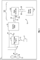
FIG. 1 is a schematic view of a vehicle including an electrical system with a motor controller, showing a power source connected to an electric motor through a source cable and a supply cable (i.e. feeder cable); -
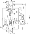
FIG. 2 is a schematic view of the motor controller electronics arrangement ofFIG. 1 , showing the coolant jacket receiving cold liquid coolant at a coolant inlet and returning heated liquid coolant to the cold plate from a coolant outlet; -
FIG. 3 is a schematic view of the portion of the motor controller electronics arrangement ofFIG. 1 , showing liquid coolant traversing a proximal portion of the feeder cable within the coolant jacket; and -
FIG. 4 is a block diagram of a method of cooling a motor controller electronics arrangement, showing operations of the method according to an illustrative and non-limiting example of the method. - Reference will now be made to the drawings wherein like reference numerals identify similar structural features or aspects of the subject disclosure. For purposes of explanation and illustration, and not limitation, a partial view of an example of a motor controller electronics arrangement in accordance with the disclosure is shown in
FIG. 1 and is designated generally byreference character 100. While the disclosure is directed to the motorcontroller electronics arrangement 100, the disclosure is applicable to all high power electronics, including inverters, converters and other power electronics assemblies. - Other embodiments of motor controller electronics arrangements, electrical systems, and methods of cooling motor controllers in motor controller electronics arrangements are provided in
FIGS. 2-4 , as will be described. The systems and methods described herein can be used to provide power to electric motors, such as in electrically propelled aircraft, though the present disclosure is not limited to electrically propelled aircraft or to any particular type of vehicle in general. - With reference to
FIG. 1 , avehicle 10, e.g., a hybrid electric aircraft, is shown. Thevehicle 10 includes apropulsor 12, agas turbine engine 14 that receivesfuel 15, e.g., from anaircraft fuel tank 17, and anelectric motor 16. Thegas turbine engine 14 andelectric motor 16 may be connected in parallel to thepropulsor 12 by agearbox 19. Thevehicle 10 also includes an electrical system 18 (otherwise referred to as an electronics assembly). - The
propulsor 12 is operably associated with thegas turbine engine 14, e.g., via a shaft and/or a gearbox. Theelectric motor 16 is operably connected to thegas turbine engine 14 and is electrically connected to theelectrical system 18. In certain examples thepropulsor 12 includes a propeller or a fan. In accordance with certain examples theelectric motor 16 is an alternating current (AC) power electric motor, such as a three (3) phase AC electric motor. - The
electrical system 18 includes apower source 20, asource bus 22, amotor controller 102, and afeed bus 24. Thepower source 20 is connected to thesource bus 22, thesource bus 22 connects thepower source 20 to themotor controller 102, and thefeed bus 24 connects themotor controller 102 to theelectric motor 16. In certain examples thepower source 20 include a direct current (DC) power source, such as a DC generator and/or a battery. In accordance with certain examples thepower source 20 includes an alternating current (AC) power source, such as an AC generator. It is contemplated that theelectric motor 16 be an alternating current (AC) motor, such as a three (3) phase electric motor. - The
motor controller 102 is arranged to convert thesource power 26 provided by thepower source 20 via thesource bus 22 into a flow offeed power 28. Thefeed power 28 is communicated by themotor controller 102 to theelectric motor 16 via thefeed bus 24 and is adapted for control of theelectric motor 16, e.g., via controlling the frequency of thefeed power 28. Thefeed power 28 causes theelectric motor 16 to rotate R thepropulsor 12. In certain examples thegas turbine engine 14 and theelectric motor 16 are arranged to cooperatively rotate thepropulsor 12 during certain operating regimes, e.g., during takeoff and climbing of an aircraft, allowing thegas turbine engine 14 to be undersized in relation to the peak horsepower requirement of thevehicle 10. - As will be appreciated by those of skill in the art in view of the present disclosure, flowing the
feed power 28 through thefeed bus 24 resistively heats thefeed bus 24, increasing temperature of thefeed bus 24. Since increasing the temperature of thefeed bus 24 increases temperature of electrical components of themotor controller 102 via conduction, thefeed bus 24 should be sized to limit the amount of heat conducted into themotor controller 102. To limit the size of the feed bus 24 (and thereby thermal conduction) the motorcontroller electronics arrangement 100 includes acoolant jacket 104. Thecoolant jacket 104 is thermally coupled to thefeed bus 24 and is arranged to limit communication of the heat Q into themotor controller 102 from thefeed bus 24. - With reference to
FIG. 2 , the motorcontroller electronics arrangement 100 is shown. The motorcontroller electronics arrangement 100 includes amotor controller 102, acoolant jacket 104, acoolant supply conduit 106, and acoolant return conduit 108. The motorcontroller electronics arrangement 100 also includes aliquid coolant 110, aliquid coolant pump 112, and aheat exchanger 114. As an alternative to the pump, other configurations could also work including passive circulation, phase change coolant, etc. - The
motor controller 102 includes ahousing 116, a solid-state switch array 118, asource terminal 120. Themotor controller 102 also includesauxiliary circuitries 122, asupply terminal 124, acold plate 126, and acontroller 128. Themotor controller 102 additionally includes acoolant supply port 130 and acoolant return port 132. - The solid-
state switch array 118,auxiliary circuitries 122, and thecold plate 126 are enclosed with theinterior 135 of thehousing 116. The solid-state switch array 118 is configured to convert the source power 26 (shown inFIG. 1 ) into the supply power 30 (shown inFIG. 1 ). In this respect thecontroller 128 is operably connected to the solid-state switch array 118 and has a motor mode 44 wherein thecontroller 128 causes the solid-state switch array 118 to convert the source power 26 (shown inFIG. 1 ) into the feed power 28 (shown inFIG. 1 ). - The solid-
state switch array 118 is operably associated with thecontroller 128 and is electrically connected to theauxiliary circuitries 122. The solid-state switch array 118 also electrically couples thesource terminal 120 to thesupply terminal 124 and is thermally coupled to the cold plate 126 (e.g., in intimate mechanical contact) for rejecting heat Q thereto while converting thesource power 26 into the supply power 30. It is contemplated that theauxiliary circuitries 122 has atemperature rating 134, e.g., a temperature below reliable operation of theauxiliary circuitries 122 is assured. In certain examples theauxiliary circuitries 122 includes one or more of a capacitor and/or an inductor. - The
source terminal 120 extends through thehousing 116 to the environment external to thehousing 116, is electrically connected to thesource bus 22, and electrically couples thesource bus 22 to the solid-state switch array 118. In the illustrated example the source terminal includes aDC source terminal 136 and aDC return terminal 138. The DC source terminal 136 seats thereon the DC source lead 26A and theDC return terminal 138 seats thereon the DC return lead 26B to communicate thesource power 26 to the solid-state switch array 118. - The
supply terminal 124 extends through thehousing 116 to the environment external to thehousing 116, is electrically connected to thefeed bus 24, and electrically couples the solid-state switch array 118 to thefeed bus 24. In the illustrated example thesupply terminal 124 is a three-phase terminal and includes an A-phase terminal 140 (corresponding to a first phase of the three phase (AC)), a B-phase terminal 142 (corresponding to a second phase of the three phase (AC)), and a C-phase terminal 144 (corresponding to a third phase of the three phase (AC)). The A-phase terminal 140 seats thereon theA-phase feeder cable 32, which electrically couples theA-phase terminal 140 to theelectric motor 16. The B-phase terminal 142 seats thereon the B-phase feeder cable 34, which electrically couples the B-phase terminal 142 to theelectric motor 16. The C-phase terminal 144 seats thereon the C-phase feeder cable 36, which electrically couples the C-phase terminal 144 to theelectric motor 16. It is to be appreciated that another form of conductor, such as a bus bar, may be used for the cables 32-36. - The
coolant supply port 130 extends through thehousing 116 and into the external environment outside of thehousing 116, is connected to thecold plate 126, and seats thereon thecoolant supply conduit 106. Thecoolant return port 132 extends through thehousing 116 and into the interior of thehousing 116, is connected to thecold plate 126, and seats thereon thecoolant return conduit 108. Thecoolant jacket 104 is arranged outside of thehousing 116, is spaced apart from thehousing 116, and extends about theA-phase feeder cable 32. More specifically, thecoolant jacket 104 fluidly couples thecoolant supply conduit 106 to thecoolant return conduit 108 and envelopes an end portion 38 of theA-phase feeder cable 32. - It is contemplated that the
liquid coolant pump 112 be arranged along thecoolant supply conduit 106 to force theliquid coolant 110 through thecoolant jacket 104 for active cooling of the end portion 38 of thefeed bus 24 by removal of heat Q from the end portion 38 of thefeed bus 24. It is also contemplated that theheat exchanger 114 be arranged along thecoolant return conduit 108 to reject the heat Q to theexternal environment 42 prior recirculation of theliquid coolant 110 through thecold plate 126. In certain examples theliquid coolant 110 includes a hydrofluoroether (HFE) composition or water/glycol fluids. Examples of suitable HFE compositions include Novec™ engineered fluids, available from the 3M Corporation of St Paul, Minnesota. - With reference to
FIG. 3 , thecoolant jacket 104 is shown according to an example. Thecoolant jacket 104 includes ajacket body 148. Thejacket body 148 defines therein acoolant channel 150 and has amotor controller end 152 with a motor controller feedercable portion aperture 154, anelectric motor end 156 with an electric motor feedercable portion aperture 158, acoolant inlet port 160, and acoolant outlet port 162. - The
coolant inlet port 160 extends through thejacket body 148 between the motor controller feedercable portion aperture 154 and the electric motor feedercable portion aperture 158, is in fluid communication with thecoolant channel 150, and fluidly couples thecoolant supply conduit 106 to thecoolant channel 150. Thecoolant outlet port 162 extends through thejacket body 148 between thecoolant inlet port 160 and the electric motor feedercable portion aperture 158, is in fluid communication with thecoolant channel 150, and fluidly couples thecoolant return conduit 108 to thecoolant channel 150. The end portion 38 of the feed bus 24 (shown inFIG. 2 ) is arranged within thecoolant channel 150 for circulating theliquid coolant 110 along the end portion 38 of thefeed bus 24 arranged within thecoolant channel 150. - As the
liquid coolant 110 traverses thecoolant channel 150 heat Q, generated resistively within thefeed bus 24 from communication therethrough of the supply power 30 (shown inFIG. 2 ), is communicated between theliquid coolant 110 and thefeed bus 24. Transfer of the heat Q causes the end portion 38 of thefeed bus 24 between the motor controller feedercable portion aperture 154 and the motor controller 102 (shown inFIG. 2 ) to run at a lower temperature than an electric motor portion 50 of thefeed bus 24 between the electric motor feedercable portion aperture 158 and the electric motor 16 (shown inFIG. 1 ). This limits conduction of the heat Q into themotor controller 102, limiting heating of the auxiliary circuitries 122 (shown inFIG. 2 ), e.g., such that the temperature of theauxiliary circuitries 122 remains thetemperature rating 134 of theauxiliary circuitries 122. - As shown in
FIG. 3 thecoolant jacket 104 extends about theA-phase feeder cable 32 and in this respect is an A-phase coolant jacket. More specifically, theA-phase feeder cable 32 extends through the motor controller feedercable portion aperture 154 and the electric motor feedercable portion aperture 158 such that only a portion of theA-phase feeder cable 32 is cooled. Applicant has determined that by removing heat from an intermediate portion A of theA-phase feeder cable 32 only, heat generated within an electric motor portion B of theA-phase feeder cable 32, e.g., a proximal portion, can be blocked from entering thehousing 116 and a motor controller portion C of theA-phase feeder cable 32, e.g., a distal portion of the feeder cable. Consequently, the motor controller portion C of theA-phase feeder cable 32 runs at a lower temperature than a temperature than the electric motor portion B of theA-phase feeder cable 32. - It is contemplated that the temperature of the motor controller portion C of the
A-phase feeder cable 32 be lower than the temperature rating 134 (shown inFIG. 2 ) of theauxiliary circuitries 122. In certain examples the electric motor portion B of theA-phase feeder cable 32 can run about 200 degrees Celsius (about 392 degrees Fahrenheit) and motor controller portion of theA-phase feeder cable 32 run at a temperature between 70 degrees Celsius (158 degrees Fahrenheit) and 200 degrees Celsius (392 degrees Fahrenheit), e.g., at 70 degrees Celsius (158 degrees Fahrenheit), and an intermediate portion 40 of theA-phase feeder cable 32 is arranged within an interior 164 of thecoolant jacket 104. - As also shown in
FIG. 3 the motorcontroller electronics arrangement 100 includes a B-phase coolant jacket 160 and a C-phase coolant jacket. The B-phase coolant jacket 160 is similar to theA-phase coolant jacket 104 and additionally extends about the B-phase feeder cable 34, is separated from the solid-state switch array 118 by thehousing 116 and is also in liquid communication with thecold plate 126. The C-phase coolant jacket 170 is similar to theA-phase coolant jacket 104 and additionally extends about the C-phase feeder cable 36, is separated from the solid-state switch array 118 by thehousing 116 and is also in liquid communication with thecold plate 126. - With reference to
FIG. 4 , amethod 200 of cooling a feeder cable, e.g., a feeder cable of the feed bus 24 (shown inFIG. 1 ), is shown. Themethod 200 includes converting DC power into AC power, e.g., the source power 26 (shown inFIG. 1 ) into the supply power 30 (shown inFIG. 1 ), as shown withbox 210. The AC power is communicated to an electric motor through a feeder cable, e.g., to the electric motor 16 (shown inFIG. 1 ) through the A-phase feeder cable 32 (shown inFIG. 3 ), as shown withbox 220. It is contemplated heat be generated with the flow of AC power through the feeder cable, e.g., the heat Q (shown inFIG. 2 ), as shown withbox 230. - As shown with
box 240, a liquid coolant is flowed through a coolant jacket from a cold plate arranged within the housing of a motor controller, e.g., the liquid coolant 110 (shown inFIG. 2 ) flowed through the coolant jacket 104 (shown inFIG. 2 ) from the cold plate 126 (shown inFIG. 2 ). It is contemplated that the feeder cable be actively cooled by the liquid coolant, e.g., by pumping the liquid coolant through the coolant jacket by the liquid coolant pump 112 (shown inFIG. 2 ), as shown withbox 242. In certain examples the liquid coolant can be flow outward from the housing and along the feeder cable in a direction toward the electric motor, e.g., from the motor controller portion C (shown inFIG. 3 ) of the feeder cable toward an electric motor portion B (shown inFIG. 3 ) of the feeder cable, as shown withbox 244. In accordance with certain examples the liquid coolant can be flowed along only a portion of the feeder cable, e.g., along the intermediate portion A (shown inFIG. 3 ) of the feeder cable, as shown withbox 246. - As shown with
box 250, heat Q is communicated from the feeder cable to the liquid coolant as the liquid coolant traverses the coolant jacket and along only the portion of the feeder cable. As shown withbox 260, the liquid coolant is then returned to the cold plate arranged within the motor controller. It is contemplated that, in certain examples, the liquid coolant can be returned to the cold plate through a heat exchanger, e.g., the heat exchanger 114 (shown inFIG. 2 ), as also shown withbox 260. It is also contemplated that, in accordance with certain examples, a motor controller portion of the feeder cable connected to the motor controller can be maintained below a temperature rating of auxiliary circuitries, e.g. the temperature rating 134 (shown inFIG. 2 ) of the auxiliary circuitries 122 (shown inFIG. 2 ), while an electric motor portion of the feeder cable is maintained at a temperature about the temperature rating of the auxiliary circuitries, as also shown withbox 260. - Vehicles, such as aircraft, commonly employ electric motors. The electric motors are generally controlled by a motor controller to provide variable frequency AC power to the electric motor to control the speed of the motor. The variable frequency AC power is communicated to the electric motor by feeder cables, which electrically connect the motor controller to the electric motor. The variable frequency AC power generally resistively heats the feeder cable is a way that corresponds to the amount of electrical power communicated to the electric motor by the feeder cable. The heat is typically removed from the feeder cables passively with a flow of ambient air across the feeder cable, typically through cooperation of the feeder cable gauge and ambient air temperature to limit the amount of heat introduced into the motor controller by the feeder cable.
- In examples described herein feeder cables are actively cooled. More specifically, the feeder cables are cooled at location outside the housing of the motor controller and proximate the housing, limiting heat communicated to the motor controller from the feeder cable. In accordance with certain examples, liquid coolant is provided to the feeder cable using coolant received from a cold plate arranged within the motor controller. It is contemplated that, in accordance with certain examples, the coolant received from the motor controller is circulated from the motor controller and through a coolant jacket surrounding a portion of the feeder cable to remove heat from the feeder cable. For example, coolant having a temperature of about 70 degrees Celsius (about 158 degrees Fahrenheit) can be introduced into the coolant jacket and communicated along a portion of the feeder cable generating heat through resistive heating otherwise sufficient to cause the cable to run at temperatures of about 200 degrees Celsius (about 392 degrees Fahrenheit). This allows the feeder cable to run relatively hot in relation to the temperature rating of auxiliary circuitries within the housing of the motor controller as the coolant jacket limits (or eliminates entirely) introduction of heat from the feeder cable into the interior of the housing of the motor controller.
- The term "about" is intended to include the degree of error associated with measurement of the particular quantity based upon the equipment available at the time of filing the application.
- The terminology used herein is for the purpose of describing particular embodiments only and is not intended to be limiting of the present disclosure. As used herein, the singular forms "a", "an" and "the" are intended to include the plural forms as well, unless the context clearly indicates otherwise. It will be further understood that the terms "comprises" and/or "comprising," when used in this specification, specify the presence of stated features, integers, steps, operations, elements, and/or components, but do not preclude the presence or addition of one or more other features, integers, steps, operations, element components, and/or groups thereof.
- While the present disclosure has been described with reference to an exemplary embodiment or embodiments, it will be understood by those skilled in the art that various changes may be made and equivalents may be substituted for elements thereof without departing from the scope of the present disclosure. In addition, many modifications may be made to adapt a particular situation or material to the teachings of the present disclosure without departing from the essential scope thereof. Therefore, it is intended that the present disclosure not be limited to the particular embodiment disclosed as the best mode contemplated for carrying out this present disclosure, but that the present disclosure will include all embodiments falling within the scope of the claims.
Claims (15)
- An electronics assembly, including,
a motor controller electronics arrangement (100), comprising:a housing (116) enclosing a solid-state switch array;a cold plate (126) arranged within the housing and in thermal communication with the solid-state switch array;a feeder cable (32) electrically connected to the solid-state switch array; anda coolant jacket (104) extending about the feeder cable and separated from the switch arrangement by the housing,wherein the feeder cable (32) is in liquid communication with the cold plate to limit communication of heat from the feeder cable to an interior of the housing. - The electronics assembly of claim 1, further comprising a coolant supply conduit fluidly coupling the coolant jacket to the cold plate and/or further comprising a coolant return conduit fluidly coupling the coolant jacket to the cold plate.
- The electronics assembly of claim 1 or 2, further comprising a liquid coolant circulating between the coolant jacket and the cold plate.
- The electronics assembly of any preceding claim, wherein the feeder cable comprises:an electric motor portion;a motor controller portion connected to the electric motor portion; andan intermediate portion connected the motor controller portion to the electric motor portion, wherein the electric motor portion of the feeder cable is spaced apart from the motor controller portion of the feeder cable by the intermediate portion of the feeder cable.
- The electronics assembly of any preceding claim, wherein the coolant jacket is spaced apart from the housing.
- The electronics assembly of any preceding claim, wherein the coolant jacket has a coolant inlet and a coolant outlet, and wherein the coolant inlet separates the coolant outlet from the housing along the feeder cable.
- The electronics assembly of claim 6, further comprising a coolant supply conduit fluidly coupling the coolant inlet to the cold plate, or further comprising a coolant return conduit fluidly coupling the coolant outlet to the cold plate, or further comprising a liquid coolant traversing the coolant jacket and in thermal communication with the feeder cable through the coolant jacket.
- The electronics assembly of any preceding claim, further comprising a source terminal electrically connected to the feeder cable by the switch arrangement, and/or further comprising an electric motor electrically connected to the switch arrangement by the feeder cable..
- The electronics assembly of any preceding claim, further comprising:a pump fluidly coupling the cold plate to the coolant jacket; anda heat exchanger fluidly coupling the coolant jacket to the cold plate.
- The electronics assembly of any preceding claim, wherein the feeder cable is an A-phase feeder cable, wherein the coolant jacket is an A-phase coolant jacket, and further comprising:a B-phase feeder cable electrically connected to the solid-state switch array; anda B-phase coolant jacket extending about the B-phase feeder cable, wherein the B-phase coolant jacket is separated from the solid-state switch array by the housing and is in liquid communication with the cold plate.
- An electrical system, comprising:an electric motor;the electronics assembly as recited in any preceding claim, wherein the feeder cable is electrically connected to the electric motor; anda power source electrically connected to the feeder cable by the solid-state switch array.
- The electrical system of claim 11, wherein the electronics assembly further comprises:a coolant supply conduit fluidly coupling the coolant jacket to the cold plate;a coolant return conduit fluidly coupling the coolant jacket to the cold plate; anda liquid coolant circulating between the coolant jacket and the cold plate, and/or wherein the coolant jacket has a coolant inlet and a coolant outlet, and wherein the coolant inlet separates the coolant outlet from the housing along the feeder cable, the motor controller electronics arrangement further comprising:a pump fluidly coupling the cold plate to the coolant jacket; anda heat exchanger fluidly coupling the coolant jacket to the cold plate.
- A method of cooling a feeder cable, comprising:at a housing enclosing a solid-state switch array, a cold plate arranged within the housing and in thermal communication with the solid-state switch array, and a feeder cable electrically connected to the solid-state switch array and having a coolant jacket extending thereabout that is separated from the solid-state switch array by the housing and in liquid communication with the cold plate,generating heat with supply power flowing through the feeder cable;flowing liquid coolant to the coolant jacket from the cold plate;communicating heat from the feeder cable to the liquid coolant as the liquid coolant traverses the coolant jacket; andreturning the liquid coolant to the cold plate.
- The method of claim 13, further comprising actively circulating the liquid coolant through the coolant jacket and along the feeder cable using a pump fluidly coupling the coolant jacket to the cold plate.
- The method of claim 13 or 14, wherein the feeder cable has a proximal portion and a distal portion, the proximal portion connecting the distal portion to the housing, the method further comprising flowing the liquid coolant outward from the housing to maintain the proximal portion at lower temperature than the distal portion of the feeder cable.
Applications Claiming Priority (1)
| Application Number | Priority Date | Filing Date | Title |
|---|---|---|---|
| US202063008105P | 2020-04-10 | 2020-04-10 |
Publications (2)
| Publication Number | Publication Date |
|---|---|
| EP3893618A1 true EP3893618A1 (en) | 2021-10-13 |
| EP3893618B1 EP3893618B1 (en) | 2023-12-27 |
Family
ID=75438615
Family Applications (1)
| Application Number | Title | Priority Date | Filing Date |
|---|---|---|---|
| EP21167380.1A Active EP3893618B1 (en) | 2020-04-10 | 2021-04-08 | Motor controller electronics arrangements with actively cooled feeder cables |
Country Status (2)
| Country | Link |
|---|---|
| US (1) | US12015324B2 (en) |
| EP (1) | EP3893618B1 (en) |
Families Citing this family (2)
| Publication number | Priority date | Publication date | Assignee | Title |
|---|---|---|---|---|
| US11807381B2 (en) * | 2021-03-16 | 2023-11-07 | Rolls-Royce Corporation | Aircraft hybrid propulsion system including cold plate for a high density power converter |
| US12096606B2 (en) * | 2022-03-25 | 2024-09-17 | Toyota Motor Engineering & Manufacturing North America, Inc. | Hybrid cooling systems for electric machines |
Citations (3)
| Publication number | Priority date | Publication date | Assignee | Title |
|---|---|---|---|---|
| EP3392148A1 (en) * | 2017-04-21 | 2018-10-24 | General Electric Company | Hybrid propulsion system for an aircraft |
| EP3392149A1 (en) * | 2017-04-21 | 2018-10-24 | General Electric Company | Propulsion system for an aircraft |
| WO2020015825A1 (en) * | 2018-07-17 | 2020-01-23 | Siemens Aktiengesellschaft | Power semiconductor module |
Family Cites Families (6)
| Publication number | Priority date | Publication date | Assignee | Title |
|---|---|---|---|---|
| US7710228B2 (en) | 2007-11-16 | 2010-05-04 | Hamilton Sundstrand Corporation | Electrical inductor assembly |
| US9178400B2 (en) | 2012-09-25 | 2015-11-03 | Hamilton Sundstrand Corporation | Cooling arrangement for a motor assembly and method of cooling a motor assembly |
| US9220184B2 (en) * | 2013-03-15 | 2015-12-22 | Hamilton Sundstrand Corporation | Advanced cooling for power module switches |
| US10696412B2 (en) | 2017-09-29 | 2020-06-30 | The Boeing Company | Combined fluid ice protection and electronic cooling system |
| US10651761B2 (en) * | 2018-09-14 | 2020-05-12 | Hamilton Sundstrand Corporation | Power converters with segregated switch and drive modules |
| JP7432322B2 (en) * | 2019-08-27 | 2024-02-16 | 株式会社Subaru | motor device |
-
2021
- 2021-04-06 US US17/223,513 patent/US12015324B2/en active Active
- 2021-04-08 EP EP21167380.1A patent/EP3893618B1/en active Active
Patent Citations (3)
| Publication number | Priority date | Publication date | Assignee | Title |
|---|---|---|---|---|
| EP3392148A1 (en) * | 2017-04-21 | 2018-10-24 | General Electric Company | Hybrid propulsion system for an aircraft |
| EP3392149A1 (en) * | 2017-04-21 | 2018-10-24 | General Electric Company | Propulsion system for an aircraft |
| WO2020015825A1 (en) * | 2018-07-17 | 2020-01-23 | Siemens Aktiengesellschaft | Power semiconductor module |
Also Published As
| Publication number | Publication date |
|---|---|
| US20210320554A1 (en) | 2021-10-14 |
| EP3893618B1 (en) | 2023-12-27 |
| US12015324B2 (en) | 2024-06-18 |
Similar Documents
| Publication | Publication Date | Title |
|---|---|---|
| CN118545247B (en) | Aircraft propulsion unit | |
| US11479145B2 (en) | Electric storage device for providing electric energy for a charging operation of at least one electrically-driven motor vehicle, and retrofit module and operating method | |
| CN110040005A (en) | The temperature control equipment of quick charge station and charge cable with charge cable | |
| EP3893618B1 (en) | Motor controller electronics arrangements with actively cooled feeder cables | |
| US10870357B2 (en) | Charging station | |
| CN101673980B (en) | Assemblies for electrical machines | |
| US9482142B2 (en) | Cooling system for an electric vehicle and method for producing a cooling system | |
| EP2450217B1 (en) | Cooling system | |
| CN112448543B (en) | Motor device | |
| US20180270994A1 (en) | Power Inverter with Liquid Cooled Busbars | |
| CN108128270B (en) | On-board power grids and motor vehicles of motor vehicles | |
| CN112154078A (en) | Charging harness device for a battery of a motor vehicle | |
| CN114447527A (en) | Liquid cooled electrical connector | |
| CN115257353A (en) | Drive systems and electric vehicles for electric vehicles | |
| CN116890628A (en) | Cooling system for electric vehicles | |
| US20250196584A1 (en) | High voltage pump and heater assembly with scavenge path | |
| EP3893620B1 (en) | Motor controller electronics arrangements with passively cooled feeder cables | |
| CN118891432A (en) | High-voltage electric fan system | |
| US20240120806A1 (en) | Cooling system for an electric traction machine for a motor vehicle | |
| CN119678360A (en) | Assembly consisting of an electric motor and a device for controlling the electric motor, and method for controlling such an assembly | |
| US20120112568A1 (en) | Cooling system for an electric machine system including an alternating current (ac) electric machine having an integrated switch assembly | |
| WO2012061219A2 (en) | Electric machine system including an alternating electric current (ac) electric machine having a switch module | |
| US12562622B2 (en) | Cooling system for effective cooling of an electric machine of a motor vehicle | |
| US12176843B2 (en) | Control apparatus for electric power generation system | |
| US20250337300A1 (en) | Electric vehicle coolant warming thermal system |
Legal Events
| Date | Code | Title | Description |
|---|---|---|---|
| PUAI | Public reference made under article 153(3) epc to a published international application that has entered the european phase |
Free format text: ORIGINAL CODE: 0009012 |
|
| STAA | Information on the status of an ep patent application or granted ep patent |
Free format text: STATUS: THE APPLICATION HAS BEEN PUBLISHED |
|
| AK | Designated contracting states |
Kind code of ref document: A1 Designated state(s): AL AT BE BG CH CY CZ DE DK EE ES FI FR GB GR HR HU IE IS IT LI LT LU LV MC MK MT NL NO PL PT RO RS SE SI SK SM TR |
|
| STAA | Information on the status of an ep patent application or granted ep patent |
Free format text: STATUS: REQUEST FOR EXAMINATION WAS MADE |
|
| 17P | Request for examination filed |
Effective date: 20220407 |
|
| RBV | Designated contracting states (corrected) |
Designated state(s): AL AT BE BG CH CY CZ DE DK EE ES FI FR GB GR HR HU IE IS IT LI LT LU LV MC MK MT NL NO PL PT RO RS SE SI SK SM TR |
|
| GRAP | Despatch of communication of intention to grant a patent |
Free format text: ORIGINAL CODE: EPIDOSNIGR1 |
|
| STAA | Information on the status of an ep patent application or granted ep patent |
Free format text: STATUS: GRANT OF PATENT IS INTENDED |
|
| INTG | Intention to grant announced |
Effective date: 20230714 |
|
| GRAS | Grant fee paid |
Free format text: ORIGINAL CODE: EPIDOSNIGR3 |
|
| GRAA | (expected) grant |
Free format text: ORIGINAL CODE: 0009210 |
|
| STAA | Information on the status of an ep patent application or granted ep patent |
Free format text: STATUS: THE PATENT HAS BEEN GRANTED |
|
| AK | Designated contracting states |
Kind code of ref document: B1 Designated state(s): AL AT BE BG CH CY CZ DE DK EE ES FI FR GB GR HR HU IE IS IT LI LT LU LV MC MK MT NL NO PL PT RO RS SE SI SK SM TR |
|
| REG | Reference to a national code |
Ref country code: GB Ref legal event code: FG4D |
|
| REG | Reference to a national code |
Ref country code: CH Ref legal event code: EP |
|
| REG | Reference to a national code |
Ref country code: DE Ref legal event code: R096 Ref document number: 602021007997 Country of ref document: DE |
|
| REG | Reference to a national code |
Ref country code: IE Ref legal event code: FG4D |
|
| PG25 | Lapsed in a contracting state [announced via postgrant information from national office to epo] |
Ref country code: GR Free format text: LAPSE BECAUSE OF FAILURE TO SUBMIT A TRANSLATION OF THE DESCRIPTION OR TO PAY THE FEE WITHIN THE PRESCRIBED TIME-LIMIT Effective date: 20240328 |
|
| REG | Reference to a national code |
Ref country code: LT Ref legal event code: MG9D |
|
| PG25 | Lapsed in a contracting state [announced via postgrant information from national office to epo] |
Ref country code: LT Free format text: LAPSE BECAUSE OF FAILURE TO SUBMIT A TRANSLATION OF THE DESCRIPTION OR TO PAY THE FEE WITHIN THE PRESCRIBED TIME-LIMIT Effective date: 20231227 |
|
| PG25 | Lapsed in a contracting state [announced via postgrant information from national office to epo] |
Ref country code: ES Free format text: LAPSE BECAUSE OF FAILURE TO SUBMIT A TRANSLATION OF THE DESCRIPTION OR TO PAY THE FEE WITHIN THE PRESCRIBED TIME-LIMIT Effective date: 20231227 |
|
| PG25 | Lapsed in a contracting state [announced via postgrant information from national office to epo] |
Ref country code: LT Free format text: LAPSE BECAUSE OF FAILURE TO SUBMIT A TRANSLATION OF THE DESCRIPTION OR TO PAY THE FEE WITHIN THE PRESCRIBED TIME-LIMIT Effective date: 20231227 Ref country code: GR Free format text: LAPSE BECAUSE OF FAILURE TO SUBMIT A TRANSLATION OF THE DESCRIPTION OR TO PAY THE FEE WITHIN THE PRESCRIBED TIME-LIMIT Effective date: 20240328 Ref country code: FI Free format text: LAPSE BECAUSE OF FAILURE TO SUBMIT A TRANSLATION OF THE DESCRIPTION OR TO PAY THE FEE WITHIN THE PRESCRIBED TIME-LIMIT Effective date: 20231227 Ref country code: ES Free format text: LAPSE BECAUSE OF FAILURE TO SUBMIT A TRANSLATION OF THE DESCRIPTION OR TO PAY THE FEE WITHIN THE PRESCRIBED TIME-LIMIT Effective date: 20231227 Ref country code: BG Free format text: LAPSE BECAUSE OF FAILURE TO SUBMIT A TRANSLATION OF THE DESCRIPTION OR TO PAY THE FEE WITHIN THE PRESCRIBED TIME-LIMIT Effective date: 20240327 |
|
| REG | Reference to a national code |
Ref country code: NL Ref legal event code: MP Effective date: 20231227 |
|
| REG | Reference to a national code |
Ref country code: AT Ref legal event code: MK05 Ref document number: 1645772 Country of ref document: AT Kind code of ref document: T Effective date: 20231227 |
|
| PG25 | Lapsed in a contracting state [announced via postgrant information from national office to epo] |
Ref country code: NL Free format text: LAPSE BECAUSE OF FAILURE TO SUBMIT A TRANSLATION OF THE DESCRIPTION OR TO PAY THE FEE WITHIN THE PRESCRIBED TIME-LIMIT Effective date: 20231227 |
|
| PG25 | Lapsed in a contracting state [announced via postgrant information from national office to epo] |
Ref country code: SE Free format text: LAPSE BECAUSE OF FAILURE TO SUBMIT A TRANSLATION OF THE DESCRIPTION OR TO PAY THE FEE WITHIN THE PRESCRIBED TIME-LIMIT Effective date: 20231227 Ref country code: RS Free format text: LAPSE BECAUSE OF FAILURE TO SUBMIT A TRANSLATION OF THE DESCRIPTION OR TO PAY THE FEE WITHIN THE PRESCRIBED TIME-LIMIT Effective date: 20231227 Ref country code: NO Free format text: LAPSE BECAUSE OF FAILURE TO SUBMIT A TRANSLATION OF THE DESCRIPTION OR TO PAY THE FEE WITHIN THE PRESCRIBED TIME-LIMIT Effective date: 20240327 Ref country code: NL Free format text: LAPSE BECAUSE OF FAILURE TO SUBMIT A TRANSLATION OF THE DESCRIPTION OR TO PAY THE FEE WITHIN THE PRESCRIBED TIME-LIMIT Effective date: 20231227 Ref country code: LV Free format text: LAPSE BECAUSE OF FAILURE TO SUBMIT A TRANSLATION OF THE DESCRIPTION OR TO PAY THE FEE WITHIN THE PRESCRIBED TIME-LIMIT Effective date: 20231227 Ref country code: HR Free format text: LAPSE BECAUSE OF FAILURE TO SUBMIT A TRANSLATION OF THE DESCRIPTION OR TO PAY THE FEE WITHIN THE PRESCRIBED TIME-LIMIT Effective date: 20231227 |
|
| PG25 | Lapsed in a contracting state [announced via postgrant information from national office to epo] |
Ref country code: IS Free format text: LAPSE BECAUSE OF FAILURE TO SUBMIT A TRANSLATION OF THE DESCRIPTION OR TO PAY THE FEE WITHIN THE PRESCRIBED TIME-LIMIT Effective date: 20240427 |
|
| PG25 | Lapsed in a contracting state [announced via postgrant information from national office to epo] |
Ref country code: CZ Free format text: LAPSE BECAUSE OF FAILURE TO SUBMIT A TRANSLATION OF THE DESCRIPTION OR TO PAY THE FEE WITHIN THE PRESCRIBED TIME-LIMIT Effective date: 20231227 Ref country code: AT Free format text: LAPSE BECAUSE OF FAILURE TO SUBMIT A TRANSLATION OF THE DESCRIPTION OR TO PAY THE FEE WITHIN THE PRESCRIBED TIME-LIMIT Effective date: 20231227 |
|
| PG25 | Lapsed in a contracting state [announced via postgrant information from national office to epo] |
Ref country code: SK Free format text: LAPSE BECAUSE OF FAILURE TO SUBMIT A TRANSLATION OF THE DESCRIPTION OR TO PAY THE FEE WITHIN THE PRESCRIBED TIME-LIMIT Effective date: 20231227 |
|
| PG25 | Lapsed in a contracting state [announced via postgrant information from national office to epo] |
Ref country code: SM Free format text: LAPSE BECAUSE OF FAILURE TO SUBMIT A TRANSLATION OF THE DESCRIPTION OR TO PAY THE FEE WITHIN THE PRESCRIBED TIME-LIMIT Effective date: 20231227 Ref country code: SK Free format text: LAPSE BECAUSE OF FAILURE TO SUBMIT A TRANSLATION OF THE DESCRIPTION OR TO PAY THE FEE WITHIN THE PRESCRIBED TIME-LIMIT Effective date: 20231227 Ref country code: RO Free format text: LAPSE BECAUSE OF FAILURE TO SUBMIT A TRANSLATION OF THE DESCRIPTION OR TO PAY THE FEE WITHIN THE PRESCRIBED TIME-LIMIT Effective date: 20231227 Ref country code: IT Free format text: LAPSE BECAUSE OF FAILURE TO SUBMIT A TRANSLATION OF THE DESCRIPTION OR TO PAY THE FEE WITHIN THE PRESCRIBED TIME-LIMIT Effective date: 20231227 Ref country code: IS Free format text: LAPSE BECAUSE OF FAILURE TO SUBMIT A TRANSLATION OF THE DESCRIPTION OR TO PAY THE FEE WITHIN THE PRESCRIBED TIME-LIMIT Effective date: 20240427 Ref country code: EE Free format text: LAPSE BECAUSE OF FAILURE TO SUBMIT A TRANSLATION OF THE DESCRIPTION OR TO PAY THE FEE WITHIN THE PRESCRIBED TIME-LIMIT Effective date: 20231227 Ref country code: CZ Free format text: LAPSE BECAUSE OF FAILURE TO SUBMIT A TRANSLATION OF THE DESCRIPTION OR TO PAY THE FEE WITHIN THE PRESCRIBED TIME-LIMIT Effective date: 20231227 Ref country code: AT Free format text: LAPSE BECAUSE OF FAILURE TO SUBMIT A TRANSLATION OF THE DESCRIPTION OR TO PAY THE FEE WITHIN THE PRESCRIBED TIME-LIMIT Effective date: 20231227 |
|
| PG25 | Lapsed in a contracting state [announced via postgrant information from national office to epo] |
Ref country code: PT Free format text: LAPSE BECAUSE OF FAILURE TO SUBMIT A TRANSLATION OF THE DESCRIPTION OR TO PAY THE FEE WITHIN THE PRESCRIBED TIME-LIMIT Effective date: 20240429 Ref country code: PL Free format text: LAPSE BECAUSE OF FAILURE TO SUBMIT A TRANSLATION OF THE DESCRIPTION OR TO PAY THE FEE WITHIN THE PRESCRIBED TIME-LIMIT Effective date: 20231227 |
|
| PG25 | Lapsed in a contracting state [announced via postgrant information from national office to epo] |
Ref country code: PT Free format text: LAPSE BECAUSE OF FAILURE TO SUBMIT A TRANSLATION OF THE DESCRIPTION OR TO PAY THE FEE WITHIN THE PRESCRIBED TIME-LIMIT Effective date: 20240429 Ref country code: PL Free format text: LAPSE BECAUSE OF FAILURE TO SUBMIT A TRANSLATION OF THE DESCRIPTION OR TO PAY THE FEE WITHIN THE PRESCRIBED TIME-LIMIT Effective date: 20231227 |
|
| REG | Reference to a national code |
Ref country code: DE Ref legal event code: R097 Ref document number: 602021007997 Country of ref document: DE |
|
| PG25 | Lapsed in a contracting state [announced via postgrant information from national office to epo] |
Ref country code: DK Free format text: LAPSE BECAUSE OF FAILURE TO SUBMIT A TRANSLATION OF THE DESCRIPTION OR TO PAY THE FEE WITHIN THE PRESCRIBED TIME-LIMIT Effective date: 20231227 |
|
| PG25 | Lapsed in a contracting state [announced via postgrant information from national office to epo] |
Ref country code: DK Free format text: LAPSE BECAUSE OF FAILURE TO SUBMIT A TRANSLATION OF THE DESCRIPTION OR TO PAY THE FEE WITHIN THE PRESCRIBED TIME-LIMIT Effective date: 20231227 |
|
| PLBE | No opposition filed within time limit |
Free format text: ORIGINAL CODE: 0009261 |
|
| STAA | Information on the status of an ep patent application or granted ep patent |
Free format text: STATUS: NO OPPOSITION FILED WITHIN TIME LIMIT |
|
| PG25 | Lapsed in a contracting state [announced via postgrant information from national office to epo] |
Ref country code: MC Free format text: LAPSE BECAUSE OF FAILURE TO SUBMIT A TRANSLATION OF THE DESCRIPTION OR TO PAY THE FEE WITHIN THE PRESCRIBED TIME-LIMIT Effective date: 20231227 |
|
| PG25 | Lapsed in a contracting state [announced via postgrant information from national office to epo] |
Ref country code: MC Free format text: LAPSE BECAUSE OF FAILURE TO SUBMIT A TRANSLATION OF THE DESCRIPTION OR TO PAY THE FEE WITHIN THE PRESCRIBED TIME-LIMIT Effective date: 20231227 |
|
| REG | Reference to a national code |
Ref country code: CH Ref legal event code: PL |
|
| 26N | No opposition filed |
Effective date: 20240930 |
|
| PG25 | Lapsed in a contracting state [announced via postgrant information from national office to epo] |
Ref country code: LU Free format text: LAPSE BECAUSE OF NON-PAYMENT OF DUE FEES Effective date: 20240408 |
|
| REG | Reference to a national code |
Ref country code: BE Ref legal event code: MM Effective date: 20240430 |
|
| PG25 | Lapsed in a contracting state [announced via postgrant information from national office to epo] |
Ref country code: LU Free format text: LAPSE BECAUSE OF NON-PAYMENT OF DUE FEES Effective date: 20240408 |
|
| PG25 | Lapsed in a contracting state [announced via postgrant information from national office to epo] |
Ref country code: BE Free format text: LAPSE BECAUSE OF NON-PAYMENT OF DUE FEES Effective date: 20240430 |
|
| PG25 | Lapsed in a contracting state [announced via postgrant information from national office to epo] |
Ref country code: BE Free format text: LAPSE BECAUSE OF NON-PAYMENT OF DUE FEES Effective date: 20240430 Ref country code: CH Free format text: LAPSE BECAUSE OF NON-PAYMENT OF DUE FEES Effective date: 20240430 |
|
| PG25 | Lapsed in a contracting state [announced via postgrant information from national office to epo] |
Ref country code: IE Free format text: LAPSE BECAUSE OF NON-PAYMENT OF DUE FEES Effective date: 20240408 |
|
| PG25 | Lapsed in a contracting state [announced via postgrant information from national office to epo] |
Ref country code: SI Free format text: LAPSE BECAUSE OF FAILURE TO SUBMIT A TRANSLATION OF THE DESCRIPTION OR TO PAY THE FEE WITHIN THE PRESCRIBED TIME-LIMIT Effective date: 20231227 |
|
| PGFP | Annual fee paid to national office [announced via postgrant information from national office to epo] |
Ref country code: DE Payment date: 20250319 Year of fee payment: 5 |
|
| PG25 | Lapsed in a contracting state [announced via postgrant information from national office to epo] |
Ref country code: CY Free format text: LAPSE BECAUSE OF FAILURE TO SUBMIT A TRANSLATION OF THE DESCRIPTION OR TO PAY THE FEE WITHIN THE PRESCRIBED TIME-LIMIT; INVALID AB INITIO Effective date: 20210408 |
|
| PG25 | Lapsed in a contracting state [announced via postgrant information from national office to epo] |
Ref country code: HU Free format text: LAPSE BECAUSE OF FAILURE TO SUBMIT A TRANSLATION OF THE DESCRIPTION OR TO PAY THE FEE WITHIN THE PRESCRIBED TIME-LIMIT; INVALID AB INITIO Effective date: 20210408 |
|
| P01 | Opt-out of the competence of the unified patent court (upc) registered |
Free format text: CASE NUMBER: UPC_APP_0018733_3893618/2025 Effective date: 20251221 |
|
| PGFP | Annual fee paid to national office [announced via postgrant information from national office to epo] |
Ref country code: GB Payment date: 20260319 Year of fee payment: 6 |
|
| PGFP | Annual fee paid to national office [announced via postgrant information from national office to epo] |
Ref country code: FR Payment date: 20260319 Year of fee payment: 6 |