EP3893533A1 - Data transmission method and apparatus - Google Patents
Data transmission method and apparatus Download PDFInfo
- Publication number
- EP3893533A1 EP3893533A1 EP18943586.0A EP18943586A EP3893533A1 EP 3893533 A1 EP3893533 A1 EP 3893533A1 EP 18943586 A EP18943586 A EP 18943586A EP 3893533 A1 EP3893533 A1 EP 3893533A1
- Authority
- EP
- European Patent Office
- Prior art keywords
- symbol
- transmission resource
- available transmission
- configuration factor
- control signaling
- Prior art date
- Legal status (The legal status is an assumption and is not a legal conclusion. Google has not performed a legal analysis and makes no representation as to the accuracy of the status listed.)
- Pending
Links
- 230000005540 biological transmission Effects 0.000 title claims abstract description 274
- 238000000034 method Methods 0.000 title claims abstract description 69
- 238000013507 mapping Methods 0.000 claims abstract description 39
- 230000011664 signaling Effects 0.000 claims description 104
- 238000012545 processing Methods 0.000 claims description 29
- 230000004044 response Effects 0.000 claims description 23
- 238000004364 calculation method Methods 0.000 claims description 13
- 238000010586 diagram Methods 0.000 description 24
- 238000004891 communication Methods 0.000 description 22
- 230000008569 process Effects 0.000 description 16
- 238000005516 engineering process Methods 0.000 description 9
- 230000006870 function Effects 0.000 description 7
- 230000003287 optical effect Effects 0.000 description 5
- 238000007726 management method Methods 0.000 description 4
- 230000005236 sound signal Effects 0.000 description 4
- 230000001133 acceleration Effects 0.000 description 2
- 230000009471 action Effects 0.000 description 2
- 230000010267 cellular communication Effects 0.000 description 2
- 230000008859 change Effects 0.000 description 2
- 238000006243 chemical reaction Methods 0.000 description 2
- 125000004122 cyclic group Chemical group 0.000 description 2
- 238000013500 data storage Methods 0.000 description 2
- 230000003993 interaction Effects 0.000 description 2
- 230000002093 peripheral effect Effects 0.000 description 2
- 238000013439 planning Methods 0.000 description 2
- 238000013468 resource allocation Methods 0.000 description 2
- 238000001228 spectrum Methods 0.000 description 2
- 230000006978 adaptation Effects 0.000 description 1
- 238000004458 analytical method Methods 0.000 description 1
- 238000003491 array Methods 0.000 description 1
- 230000001413 cellular effect Effects 0.000 description 1
- 230000000295 complement effect Effects 0.000 description 1
- 238000010276 construction Methods 0.000 description 1
- 238000001514 detection method Methods 0.000 description 1
- 238000005562 fading Methods 0.000 description 1
- 238000003384 imaging method Methods 0.000 description 1
- 239000004973 liquid crystal related substance Substances 0.000 description 1
- 230000007774 longterm Effects 0.000 description 1
- 229910044991 metal oxide Inorganic materials 0.000 description 1
- 150000004706 metal oxides Chemical class 0.000 description 1
- 238000010295 mobile communication Methods 0.000 description 1
- 238000012986 modification Methods 0.000 description 1
- 230000004048 modification Effects 0.000 description 1
- 230000010363 phase shift Effects 0.000 description 1
- 230000011218 segmentation Effects 0.000 description 1
- 239000004065 semiconductor Substances 0.000 description 1
- 230000003068 static effect Effects 0.000 description 1
- 230000009466 transformation Effects 0.000 description 1
Images



Classifications
-
- H—ELECTRICITY
- H04—ELECTRIC COMMUNICATION TECHNIQUE
- H04L—TRANSMISSION OF DIGITAL INFORMATION, e.g. TELEGRAPHIC COMMUNICATION
- H04L5/00—Arrangements affording multiple use of the transmission path
- H04L5/0001—Arrangements for dividing the transmission path
- H04L5/0003—Two-dimensional division
- H04L5/0005—Time-frequency
- H04L5/0007—Time-frequency the frequencies being orthogonal, e.g. OFDM(A) or DMT
-
- H—ELECTRICITY
- H04—ELECTRIC COMMUNICATION TECHNIQUE
- H04L—TRANSMISSION OF DIGITAL INFORMATION, e.g. TELEGRAPHIC COMMUNICATION
- H04L27/00—Modulated-carrier systems
- H04L27/26—Systems using multi-frequency codes
- H04L27/2601—Multicarrier modulation systems
- H04L27/2626—Arrangements specific to the transmitter only
- H04L27/2627—Modulators
- H04L27/2634—Inverse fast Fourier transform [IFFT] or inverse discrete Fourier transform [IDFT] modulators in combination with other circuits for modulation
- H04L27/2636—Inverse fast Fourier transform [IFFT] or inverse discrete Fourier transform [IDFT] modulators in combination with other circuits for modulation with FFT or DFT modulators, e.g. standard single-carrier frequency-division multiple access [SC-FDMA] transmitter or DFT spread orthogonal frequency division multiplexing [DFT-SOFDM]
-
- H—ELECTRICITY
- H04—ELECTRIC COMMUNICATION TECHNIQUE
- H04L—TRANSMISSION OF DIGITAL INFORMATION, e.g. TELEGRAPHIC COMMUNICATION
- H04L27/00—Modulated-carrier systems
- H04L27/26—Systems using multi-frequency codes
- H04L27/2601—Multicarrier modulation systems
- H04L27/2602—Signal structure
- H04L27/26025—Numerology, i.e. varying one or more of symbol duration, subcarrier spacing, Fourier transform size, sampling rate or down-clocking
-
- H—ELECTRICITY
- H04—ELECTRIC COMMUNICATION TECHNIQUE
- H04L—TRANSMISSION OF DIGITAL INFORMATION, e.g. TELEGRAPHIC COMMUNICATION
- H04L5/00—Arrangements affording multiple use of the transmission path
- H04L5/003—Arrangements for allocating sub-channels of the transmission path
- H04L5/0044—Allocation of payload; Allocation of data channels, e.g. PDSCH or PUSCH
-
- H—ELECTRICITY
- H04—ELECTRIC COMMUNICATION TECHNIQUE
- H04W—WIRELESS COMMUNICATION NETWORKS
- H04W72/00—Local resource management
- H04W72/20—Control channels or signalling for resource management
-
- H—ELECTRICITY
- H04—ELECTRIC COMMUNICATION TECHNIQUE
- H04L—TRANSMISSION OF DIGITAL INFORMATION, e.g. TELEGRAPHIC COMMUNICATION
- H04L5/00—Arrangements affording multiple use of the transmission path
- H04L5/0091—Signalling for the administration of the divided path, e.g. signalling of configuration information
- H04L5/0092—Indication of how the channel is divided
-
- H—ELECTRICITY
- H04—ELECTRIC COMMUNICATION TECHNIQUE
- H04W—WIRELESS COMMUNICATION NETWORKS
- H04W72/00—Local resource management
- H04W72/04—Wireless resource allocation
- H04W72/044—Wireless resource allocation based on the type of the allocated resource
Definitions
- the present invention relates to the technical field of communication, and more particularly, to a data transmission method and apparatus.
- V2X Vehicle to Everything
- V2X refers to a new-generation information communication technology for connecting vehicles to everything.
- V2X includes Vehicle to Vehicle (V2V), Vehicle to Pedestrian (V2P), and Vehicle to Infrastructure (V2I).
- Cellular based V2X (C-V2X) is a wireless communication technology for vehicles formed based on such as a 3rd-Generation (3G)/4th-Generation (4G)/5th-Generation (5G) cellular communication technology, and usually includes two types of communication interfaces: one is short-distance direct communication interface (PC5) between a vehicle, a pedestrian and an infrastructure, and the other is a cellular communication interface (Uu) capable of implementing long-distance reliable communication of a larger range.
- a communication standard for the PC5 interface in V2X is based on Device to Device (D2D), and a broadcast communication manner is used, namely information is sent by broadcasting to multiple vehicles from a single vehicle.
- D2D Device to Device
- a subcarrier spacing is fixed to be 15KHz, and scheduling is performed in a unit of subframe.
- the length of a subframe is 1ms, and a subframe includes 14 symbols.
- rate matching for data the number of bits that can be borne is calculated according to loads of the 14 symbols.
- GP Guard Period
- Examples of the invention provide a method and apparatus for data transmission.
- the technical solutions are implemented as follows.
- a method for data transmission method applied to a sending device and including: during performing resource mapping of data to be transmitted onto a first symbol of an available transmission resource, determining a first subcarrier spacing, at least one target subcarrier, a number of inverse fast fourier transform (IFFT) points and a zero-setting length for the first symbol of the available transmission resource, according to a carrier spacing configuration factor and a second subcarrier spacing for a second symbol of the available transmission resource; mapping, in a frequency domain, the data to be transmitted to each of the at least one target subcarrier; modulating the data to be transmitted according to each of the at least one target subcarrier and the number of IFFT points to obtain a time-domain symbol; setting foremost information of the zero-setting length in the time-domain symbol to 0 to obtain an output symbol; and transmitting the output symbol.
- IFFT inverse fast fourier transform
- resource mapping is performed in the frequency domain using the first subcarrier spacing determined based on the carrier spacing configuration factor, and the foremost information of the zero-setting length in the time-domain symbol obtained by modulation is set to 0.
- a receiving device does not process or perform statistics on the foremost information of the zero-setting length in the output symbol, and instead, modulates and processes remaining information in the output symbol except the zero-setting length to obtain the data to be transmitted, so that a function as GP is realized.
- the problem in the related art that the receiving device loses useful information of at least one symbol because no data is sent on the last symbol can be solved.
- the decoding performance can be improved, and the quality of service and the system performance can be improved.
- the carrier spacing configuration factor is equal to 1 in response to that a carrier frequency band of the available transmission resource is greater than 6GHz; or, a value of the carrier spacing configuration factor includes 1, 2, or 3 in response to that the carrier frequency band of the available transmission resource is less than 6GHz.
- the method further includes one of following acts: receiving a first control signaling from a network access device, and parsing the first control signaling to obtain the carrier spacing configuration factor; receiving a second control signaling from a cluster header device in a cluster to which the sending device belongs, and parsing the second control signaling to obtain the carrier spacing configuration factor; or determining the carrier spacing configuration factor according to a processing capability of the sending device.
- the method further includes: sending a third control signaling to a receiving device, the third control signaling including the carrier spacing configuration factor.
- a method for data transmission is provided, applied to a receiving device and including: determining a first subcarrier spacing, a number of fast fourier transform (FFT) points and a zero-setting length for a first symbol of an available transmission resource of a sending device according to a carrier spacing configuration factor; and in response to receiving an output symbol from the sending device, determining data to be transmitted according to the carrier spacing configuration factor, the number of FFT points and remaining information in the output symbol except the zero-setting length.
- FFT fast fourier transform
- the method further includes one of following acts: receiving a third control signaling from the sending device, and parsing the third control signaling to obtain the carrier spacing configuration factor; receiving a fourth control signaling from a network access device, and parsing the fourth control signaling to obtain the carrier spacing configuration factor; or receiving a fifth control signaling from a cluster header device in a cluster to which the receiving device belongs, and parsing the fifth control signaling to obtain the carrier spacing configuration factor.
- an apparatus for data transmission including: a first determination module, configured to: during performing resource mapping of data to be transmitted onto a first symbol of an available transmission resource, determine a first subcarrier spacing, at least one target subcarrier, a number of inverse fast fourier transform (IFFT) points and a zero-setting length for the first symbol of the available transmission resource, according to a carrier spacing configuration factor and a second subcarrier spacing for a second symbol of the available transmission resource; a mapping module, configured to map, in a frequency domain, the data to be transmitted to each of the at least one target subcarrier; a modulation module, configured to modulate the data to be transmitted according to each of the at least one target subcarrier and the number of IFFT points to obtain a time-domain symbol; a processing module, configured to set foremost information of the zero-setting length in the time-domain symbol to 0 to obtain an output symbol; and a transmitting module, configured to transmit the output symbol.
- IFFT inverse fast fourier transform
- the carrier spacing configuration factor is equal to 1 in response to that a carrier frequency band of the available transmission resource is greater than 6GHz; or a value of the carrier spacing configuration factor includes 1, 2, or 3 in response to that the carrier frequency band of the available transmission resource is less than 6GHz.
- the apparatus may further include one of following: a first receiving module, configured to receive a first control signaling from a network access device, and parse the first control signaling to obtain the carrier spacing configuration factor; a second receiving module, configured to receive a second control signaling from a cluster header device in a cluster to which the sending device belongs, and parse the second control signaling to obtain the carrier spacing configuration factor; or a second determination module, configured to determine the carrier spacing configuration factor according to a processing capability of the sending device.
- a first receiving module configured to receive a first control signaling from a network access device, and parse the first control signaling to obtain the carrier spacing configuration factor
- a second receiving module configured to receive a second control signaling from a cluster header device in a cluster to which the sending device belongs, and parse the second control signaling to obtain the carrier spacing configuration factor
- a second determination module configured to determine the carrier spacing configuration factor according to a processing capability of the sending device.
- the apparatus may further include: a sending module, configured to send a third control signaling to a receiving device, the third control signaling including the carrier spacing configuration factor.
- an apparatus for data transmission apparatus including: a third determination module, configured to determine a first subcarrier spacing, a number of fast fourier transform (FFT) points and a zero-setting length for a first symbol of an available transmission resource of a sending device according to a carrier spacing configuration factor; and a fourth determination module, configured to: in response to receiving an output symbol from the sending device, determine data to be transmitted according to the carrier spacing configuration factor, the number of FFT points and remaining information in the output symbol except the zero-setting length.
- FFT fast fourier transform
- the apparatus may further include one of following: a third receiving module, configured to receive a third control signaling from the sending device, and parsing the third control signaling to obtain the carrier spacing configuration factor; a fourth receiving module, configured to receive a fourth control signaling from a network access device, and parsing the fourth control signaling to obtain the carrier spacing configuration factor; or a fifth receiving module, configured to receive a fifth control signaling from a cluster header device in a cluster to which the receiving device belongs, and parsing the fifth control signaling to obtain the carrier spacing configuration factor.
- an apparatus for data transmission including: a processor; and a memory configured to store instructions executable for the processor, wherein the processor may be configured to: during performing resource mapping of data to be transmitted onto a first symbol of an available transmission resource, determine a first subcarrier spacing, at least one target subcarrier, a number of inverse fast fourier transform (IFFT) points and a zero-setting length for the first symbol of the available transmission resource, according to a carrier spacing configuration factor and a second subcarrier spacing for a second symbol of the available transmission resource; map, in a frequency domain, the data to be transmitted to each of the at least one target subcarrier; modulate the data to be transmitted according to each of the at least one target subcarrier and the number of IFFT points to obtain a time-domain symbol; set foremost information of the zero-setting length in the time-domain symbol to 0 to obtain an output symbol; and transmit the output symbol.
- IFFT inverse fast fourier transform
- an apparatus for data transmission including: a processor; and a memory configured to store instructions executable for the processor, wherein the processor is configured to: determine a first subcarrier spacing, a number of fast fourier transform (FFT) points and a zero-setting length for a first symbol of an available transmission resource of a sending device according to a carrier spacing configuration factor; and in response to receiving an output symbol from the sending device, determine data to be transmitted according to the carrier spacing configuration factor, the number of FFT points and remaining information in the output symbol except the zero-setting length.
- FFT fast fourier transform
- a computer-readable storage medium having stored thereon computer instructions which, when executed by a processor, implement the steps of the method as described in the first aspect.
- a computer-readable storage medium having stored thereon computer instructions which, when executed by a processor, implement the steps of the method as described in the second aspect.
- the examples of the invention provide a method for data transmission, which is applied to a sending device.
- the method includes the following. During performing resource mapping of data to be transmitted onto a first symbol of an available transmission resource, a first subcarrier spacing, at least one target subcarrier, a number of IFFT points and a zero-setting length for the first symbol of the available transmission resource are determined according to a carrier spacing configuration factor and a second subcarrier spacing for a second symbol of the available transmission resource.
- the data to be transmitted is mapped to each of the at least one target subcarrier in a frequency domain.
- the data to be transmitted is modulated according to each of the at least one target subcarrier and the number of IFFT points to obtain a time-domain symbol. Foremost information of the zero-setting length in the time-domain symbol is set to 0 to obtain an output symbol.
- the output symbol is transmitted.
- resource mapping is performed in the frequency domain using the first subcarrier spacing determined based on the carrier spacing configuration factor, and the foremost information of the zero-setting length in the time-domain symbol obtained by modulation is set to 0.
- a receiving device does not process or perform statistics on the foremost information of the zero-setting length in the output symbol, and instead, modulates and processes remaining information in the output symbol except the zero-setting length to obtain the data to be transmitted, so that a function as GP is realized.
- the problem in the related art that the receiving device loses useful information of at least one symbol because no data is sent on the last symbol can be solved.
- the decoding performance can be improved, and the quality of service and the system performance can be improved.
- the method for data transmission provided in the examples of the invention may be applied to a 4G/5G-based C-V2X communication network.
- the sending device and receiving device involved in the invention may include, for example, a device like a vehicle-mounted device, a road-side unit, or a handheld device.
- the handheld device may include for example an electronic device like a smart phone, a notebook computer, or an intelligent wearable device.
- a network access device involved in the invention may include for example a communication device that provides wireless access service for a terminal, like a base station or a relay station.
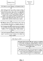
- FIG. 1 illustrates a flow chart of a method for data transmission according to an example.
- An execution body of the method for data transmission may be a sending device.
- the method includes the following Steps 101 to 105.
- Step 101 during performing resource mapping of data to be transmitted onto a first symbol of an available transmission resource, a first subcarrier spacing, at least one target subcarrier, a number of IFFT points and a zero-setting length for the first symbol of the available transmission resource are determined according to a carrier spacing configuration factor and a second subcarrier spacing for a second symbol of the available transmission resource.
- the data to be transmitted may include user data or a pilot signal.
- the available transmission resource refers to time-domain, frequency-domain, space-domain and code-domain practical physical transmission resources allocated to the sending device.
- the first symbol of the available transmission resource may be a first symbol sent by the sending device, or may be a first symbol in a time slot.
- the second subcarrier spacing for the second symbol of the available transmission resource may be a subcarrier spacing designated by a network access device upon resource allocation.
- an implementation of the operation that the sending device pre-obtains the carrier spacing configuration factor may include any one or combination of the following modes.
- the sending device may send a third control signaling to a receiving device after determining the carrier spacing configuration factor.
- the third control signaling includes the carrier spacing configuration factor.
- the carrier spacing configuration factor is represented by a preset bit in the third control signaling.
- Step 102 the data to be transmitted is mapped to each of the at least one target subcarrier in a frequency domain.
- Step 103 the data to be transmitted is modulated according to each of the at least one target subcarrier and the number of IFFT points to obtain a time-domain symbol.
- Orthogonal Frequency Division Multiplexing (OFDM) modulation is performed on the data to be transmitted according to each of the at least one target subcarrier and the number of IFFT points to obtain the time-domain symbol.
- OFDM Orthogonal Frequency Division Multiplexing
- Step 104 foremost information of the zero-setting length in the time-domain symbol is set to 0 to obtain an output symbol.
- Step 105 the output symbol is transmitted.
- the receiving device when receiving the output symbol from the sending device, the receiving device does not process or perform statistics on the foremost information of the zero-setting length in the output symbol, and instead, demodulates and processes remaining information in the output symbol except the zero-setting length to obtain the data to be transmitted.
- resource mapping is performed in the frequency domain using the first subcarrier spacing determined based on the carrier spacing configuration factor, and the foremost information of the zero-setting length in the time-domain symbol obtained by modulation is set to 0.
- a receiving device does not process or perform statistics on the foremost information of the zero-setting length in the output symbol, and instead, modulates and processes remaining information in the output symbol except the zero-setting length to obtain the data to be transmitted, so that a function as GP is realized.
- the problem in the related art that the receiving device loses useful information of at least one symbol because no data is sent on the last symbol can be solved.
- the decoding performance can be improved, and the quality of service and the system performance can be improved.
- an implementation of the operation that the first subcarrier spacing, the at least one target subcarrier, the number of IFFT points and the zero-setting length for the first symbol of the available transmission resource are determined according to the carrier spacing configuration factor and the second subcarrier spacing for the second symbol of the available transmission resource may include that:
- T2 is the second subcarrier spacing for the second symbol of the available transmission resource, and n is the carrier spacing configuration factor.
- Each of the at least one target subcarrier is determined in the frequency domain of the first symbol of the available transmission resource according to the first subcarrier spacing for the first symbol of the available transmission resource.
- the carrier spacing configuration factor is equal to 1 when a carrier frequency band of the available transmission resource is greater than 6GHz; or, a value of the carrier spacing configuration factor may include 1, 2, or 3 when the carrier frequency band of the available transmission resource is less than 6GHz.
- subcarrier spacings 60khz and 120khz may be scheduled by a system when the carrier frequency band is greater than 6GHz. Namely there is a double relationship only, and correspondingly, n is 1. Subcarrier spacings 15khz, 30khz, 60khz, and 120khz may be scheduled by the system when the carrier frequency band is below 6GHz. Namely there are double, quadruple and octuple relationships only, and correspondingly, n is 1, 2, or 3.
- the carrier spacing configuration factor may be represented by 2 bits.
- '00' represents that the carrier spacing configuration factor is 1
- '01' represents that the carrier spacing configuration factor is 2
- '11' represents that the carrier spacing configuration factor is 3.
- FIG. 2 illustrates a flow chart of a method for data transmission according to an example.
- An execution body of the method for data transmission may be a receiving device.
- the method includes the following Steps 201 to 202.
- Step 201 a first subcarrier spacing, a number of FFT points and a zero-setting length for a first symbol of an available transmission resource of a sending device are determined according to a carrier spacing configuration factor.
- an implementation of the operation that the receiving device pre-obtains the carrier spacing configuration factor may include any one or combination of the following modes.
- Step 202 in response to receiving an output symbol from the sending device, data to be transmitted is determined according to the carrier spacing configuration factor, the number of FFT points and remaining information in the output symbol except the zero-setting length.
- the carrier spacing configuration factor corresponding to the sending device is pre-obtained.
- the receiving device When receiving the output symbol from the sending device, the receiving device does not process or perform statistics on the foremost information of the zero-setting length in the output symbol, and instead, modulates and processes remaining information in the output symbol except the zero-setting length, to obtain the data to be transmitted, so that a function as GP is realized. Since a last symbol of each subframe contains information, the problem in the related art that the receiving device loses useful information of at least one symbol because no data is sent on the last symbol can be solved. The decoding performance can be improved, and thus the quality of service and the system performance can be improved.
- the number of FFT points N3 for the first symbol of the available transmission resource of the sending device is calculated according to a number of FFT points N4 for the second symbol of the available transmission resource of the sending device.
- FIG. 3 illustrates a flow chart of a method for data transmission according to an example.
- a sending device and receiving device in a 4G/5G-based C-V2X communication network cooperate to implement the method.
- the method for data transmission involved in the invention may include the following Steps 301 to 307.
- Step 301 the sending device obtains a carrier spacing configuration factor.
- Step 302 during performing resource mapping of data to be transmitted onto a first symbol of an available transmission resource, the sending device determines a first subcarrier spacing, at least one target subcarrier, a number of IFFT points and a zero-setting length for the first symbol of the available transmission resource according to the carrier spacing configuration factor and a second subcarrier spacing for a second symbol of the available transmission resource.
- Step 303 the sending device maps the data to be transmitted to each of the at least one target subcarrier in a frequency domain.
- Step 304 the sending device modulates the data to be transmitted according to each of the at least one target subcarrier and the number of IFFT points to obtain a time-domain symbol.
- Step 305 the sending device sets foremost information of the zero-setting length in the time-domain symbol to 0 to obtain an output symbol.
- Step 306 the sending device transmits the output symbol.
- Step 307 the receiving device determines the first subcarrier spacing, a number of FFT points and the zero-setting length for the first symbol of the available transmission resource of the sending device according to the carrier spacing configuration factor.
- Step 308 when receiving the output symbol from the sending device, the receiving device determines the data to be transmitted according to the carrier spacing configuration factor, the number of FFT points and remaining information in the output symbol except the zero-setting length.
- the receiving device does not make statistics on the foremost information of the zero-setting length in the first symbol in the output symbol, and performs analog signal reception and/or Automatic Gain Control (AGC) operation and processing on the remaining information in the first symbol in the output symbol except the zero-setting length, and the other symbols of the output symbol to obtain the data to be transmitted.
- AGC Automatic Gain Control
- the number of FFT points for the first symbol of the output symbol is 1/2 n times the number of FFT points for the second symbol.
- the number of FFT points for the second symbol is designated by a network access device upon resource allocation.
- the resource mapping is performed in the frequency domain using the first subcarrier spacing determined based on the carrier spacing configuration factor, and the foremost information of the zero-setting length in the time-domain symbol obtained by modulation is set to 0.
- the receiving device does not process or perform statistics on the foremost information of the zero-setting length in the output symbol, and instead, modulates and processes the remaining information in the output symbol except the zero-setting length to obtain the data to be transmitted, so that a function as GP is realized.
- a processing process of a physical layer in a mobile communication system may include the following steps.
- Step 1) a Cyclic Redundancy Check (CRC) code is added to each transport block: for ensuring error detection of a channel, all data blocks sent by a Media Access Control (MAC) layer need to be added to a CRC code.
- CRC Cyclic Redundancy Check
- Step 2 code block segmentation, and addition of CRC information to code block segments: for ensuring that the size of a code block is not greater than a threshold, for example, 6,144 bits, the transport block needs to be segmented; and for ensuring that the receiving device can stop erroneous decoding in advance, the CRC information is further added to each code block.
- a threshold for example, 6,144 bits
- Step 3 channel coding: a k-bit sequence is mapped to an m-bit sequence.
- the bits that have not been coded are referred to as original bits or source bits, and coded bits are referred to as codewords or codeword bits.
- codewords or codeword bits are referred to as codewords or codeword bits.
- m is more than or equal to k, and k/m is referred to as a code rate.
- Step 4 rate matching is performed: it is judged whether a practically transmitted physical resource is matched with the coded bits or not. If the practically transmitted physical resource is greater than the number of the coded bits, the coded bits need to be duplicated to a certain extent according to a certain rule. If the practically transmitted physical resource is less than the number of the coded bits, part of coded bits need to be removed, to enable that a transmission capability is matched with the transmitted data.
- RBs Resource Blocks
- QPSK Quadrature Phase Shift Keying
- Step 5 cascading of code blocks.
- Step 6 channel interleaving: for avoiding the influence of selective fading of the channel on information, the data to be transmitted needs to be interleaved.
- mapping from a logical channel to a physical channel during performing resource mapping of the data to be transmitted onto a first symbol of an available transmission resource, a first subcarrier spacing, at least one target subcarrier, a number of IFFT points and a zero-setting length for the first symbol of the available transmission resource are determined according to a carrier spacing configuration factor and a second subcarrier spacing for a second symbol of the available transmission resource.
- the data to be transmitted is mapped to each of the at least one target subcarrier in the frequency domain.
- a subcarrier spacing of the at least one target subcarrier is the first subcarrier spacing.
- the available transmission resource refers to time-domain, frequency-domain, space-domain and code-domain practical physical transmission resources allocated to the sending device.
- a value of the carrier spacing configuration factor n may be determined according to a carrier frequency band of the available transmission resource.
- FIG. 4 to FIG. 6 illustrate schematic diagrams of frequency-domain resource mapping on a first symbol according to an example. There is made such a hypothesis that the carrier frequency band of the available transmission resource is less than 6GHz. FIG. 4 to FIG. 6 illustrate three different frequency-domain resource mapping manners respectively.
- Step 8 OFDM modulation is performed, and a Cyclic Prefix (CP) is added: OFDM modulation is performed on the data to be transmitted according to each of the at least one target subcarrier and the number of IFFT points to obtain a time-domain symbol.
- the number of IFFT points for the first symbol is 1/2 n times that for the second symbol.
- a foremost (1-1/2 n ) length of information in the time-domain symbol is set to 0 to obtain an output symbol.
- Step 9 parallel-to-serial conversion: parallel-to-serial conversion is completed, and the output symbol is transmitted according to a time sequence.
- the receiving device pre-obtains a mapping manner for the first symbol of the available transmission resource of the sending device.
- the receiving device does not make statistics on the foremost (1-1/2 n ) length of information in the output symbol, and only performs analog signal reception and/or AGC operation and processing on remaining information in the first symbol in the output symbol except the foremost (1-1/2 n ) length of information and performs analog signal reception on other subsequently received symbols in the output symbol.
- a number of FFT points for the first symbol corresponding to the output symbol is 1/2n times that for the second symbol, thereby realizing a function as GP. Since a last symbol of each subframe contains information, the problem in the related art that the receiving device loses useful information of at least one symbol because no data is sent on the last symbol can be solved, and the decoding performance and the system performance can be improved.
- FIG. 7 illustrates a block diagram of an apparatus for data transmission according to an example.
- the apparatus may be applied to a sending device.
- the apparatus for data transmission includes a first determination module 701, a mapping module 702, a modulation module 703, a processing module 704 and a transmitting module 705.
- the first determination module 701 is configured to: during performing resource mapping of data to be transmitted onto a first symbol of an available transmission resource, determine a first subcarrier spacing, at least one target subcarrier, a number of inverse fast fourier transform (IFFT) points and a zero-setting length for the first symbol of the available transmission resource, according to a carrier spacing configuration factor and a second subcarrier spacing for a second symbol of the available transmission resource.
- IFFT inverse fast fourier transform
- the mapping module 702 is configured to map, in a frequency domain, the data to be transmitted to each of the at least one target subcarrier.
- the modulation module 703 is configured to modulate the data to be transmitted according to each of the at least one target subcarrier and the number of IFFT points to obtain a time-domain symbol.
- the processing module 704 is configured to set foremost information of the zero-setting length in the time-domain symbol to 0 to obtain an output symbol.
- the transmitting module 705 is configured to transmit the output symbol.
- resource mapping is performed in the frequency domain using the first subcarrier spacing determined based on the carrier spacing configuration factor, and the foremost information of the zero-setting length in the time-domain symbol obtained by modulation is set to 0.
- a receiving device does not process or perform statistics on the foremost information of the zero-setting length in the output symbol, and instead, modulates and processes remaining information in the output symbol except the zero-setting length to obtain the data to be transmitted, so that a function as GP is realized. Since a last symbol of each subframe contains information, the problem that the receiving device loses useful information of at least one symbol because no data is sent on the last symbol can be solved.
- the decoding performance can be improved, and the quality of service and the system performance can be improved.
- the first determination module 701 may be further configured to include a first calculation submodule 801, a determination submodule 802, a second calculation submodule 803 and a third calculation submodule 804.
- T2 is the second subcarrier spacing for the second symbol of the available transmission resource, and n is the carrier spacing configuration factor
- the determination submodule 802 is configured to determine each of the at least one target subcarrier in the frequency domain of the first symbol of the available transmission resource according to the first subcarrier spacing for the first symbol of the available transmission resource.
- the carrier spacing configuration factor is equal to 1 in response to that a carrier frequency band of the available transmission resource is greater than 6GHz; or a value of the carrier spacing configuration factor includes 1, 2, or 3 in response to that the carrier frequency band of the available transmission resource is less than 6GHz.
- the apparatus for data transmission of in FIG. 7 may further include a first receiving module 901.
- the first receiving module 901 is configured to receive a first control signaling sent by a network access device and parse the first control signaling to obtain the carrier spacing configuration factor.
- the apparatus for data transmission of in FIG. 7 may further include a second receiving module 902.
- the second receiving module 902 is configured to receive a second control signaling from a cluster header device in a cluster to which the sending device belongs, and parse the second control signaling to obtain the carrier spacing configuration factor.
- the apparatus for data transmission of in FIG. 7 may further include a second determination module 903.
- the second determination module 903 is configured to determine the carrier spacing configuration factor according to a processing capability of the sending device.
- the apparatus for data transmission of in FIG. 7 may further include a sending module 1001.
- the sending module 1001 is configured to send a third control signaling to a receiving device.
- the third control signaling includes the carrier spacing configuration factor.
- FIG. 11 illustrates a block diagram of an apparatus for data transmission according to an example.
- the apparatus may be applied to a receiving device.
- the apparatus for data transmission includes a third determination module 1101 and a fourth determination module 1102.
- the third determination module 1001 is configured to determine a first subcarrier spacing, a number of fast fourier transform (FFT) points and a zero-setting length for a first symbol of an available transmission resource of a sending device, according to a carrier spacing configuration factor.
- FFT fast fourier transform
- the fourth determination module 1102 is configured to: in response to receiving an output symbol from the sending device, determine data to be transmitted according to the carrier spacing configuration factor, the number of FFT points and remaining information in the output symbol except the zero-setting length.
- the apparatus for data transmission of FIG. 11 may further include a third receiving module 1201.
- the third receiving module 1201 is configured to receive a third control signaling from the sending device, and parse the third control signaling to obtain the carrier spacing configuration factor.
- the apparatus for data transmission of FIG. 11 may further include a fourth receiving module 1202.
- the fourth receiving module 1202 is configured to receive a fourth control signaling from a network access device, and parse the fourth control signaling to obtain the carrier spacing configuration factor.
- the apparatus for data transmission of in FIG. 11 may further include a fifth receiving module 1203.
- the fifth receiving module 1203 is configured to receive a fifth control signaling from a cluster header device in a cluster to which the receiving device belongs, and parse the fifth control signaling to obtain the carrier spacing configuration factor.
- FIG. 13 illustrates a block diagram of an apparatus 1300 for data transmission according to an example.
- the apparatus 1300 for data transmission is applied to a sending device, and includes: a processor 1301; and a memory 1302 configured to store instructions executable for the processor.
- the processor 1301 is configured to: during performing resource mapping of data to be transmitted onto a first symbol of an available transmission resource, determine a first subcarrier spacing, at least one target subcarrier, a number of inverse fast fourier transform (IFFT) points and a zero-setting length for the first symbol of the available transmission resource, according to a carrier spacing configuration factor and a second subcarrier spacing for a second symbol of the available transmission resource; map, in a frequency domain, the data to be transmitted to each of the at least one target subcarrier; modulate the data to be transmitted according to each of the at least one target subcarrier and the number of IFFT points to obtain a time-domain symbol; set foremost information of the zero-setting length in the time-domain symbol to 0 to obtain an output symbol; and transmit the output symbol.
- IFFT inverse fast fourier transform
- the carrier spacing configuration factor is equal to 1 in response to that a carrier frequency band of the available transmission resource is greater than 6GHz; or a value of the carrier spacing configuration factor includes 1, 2, or 3 in response to that the carrier frequency band of the available transmission resource is less than 6GHz.
- the processor 1301 may be further configured to perform one of following acts: receiving a first control signaling from a network access device, and parsing the first control signaling to obtain the carrier spacing configuration factor; receiving a second control signaling from a cluster header device in a cluster to which the sending device belongs, and parsing the second control signaling to obtain the carrier spacing configuration factor; or determining the carrier spacing configuration factor according to a processing capability of the sending device.
- the processor 1301 may be further configured to: send a third control signaling to a receiving device, the third control signaling including the carrier spacing configuration factor.
- FIG. 14 illustrates a block diagram of an apparatus 1400 for data transmission according to an example.
- the apparatus 1400 for data transmission is applied to a receiving device, and includes: a processor 1401; and a memory 1402 configured to store an instruction executable for the processor.
- the processor 1401 is configured to: determine a first subcarrier spacing, a number of fast fourier transform (FFT) points and a zero-setting length for a first symbol of an available transmission resource of a sending device, according to a carrier spacing configuration factor; and in response to receiving an output symbol from the sending device, determine data to be transmitted according to the carrier spacing configuration factor, the number of FFT points and remaining information in the output symbol except the zero-setting length.
- FFT fast fourier transform
- the processor 1401 may be further configured to perform one of following acts: receiving a third control signaling from the sending device, and parse the third control signaling to obtain the carrier spacing configuration factor; receiving a fourth control signaling from a network access device, and parse the fourth control signaling to obtain the carrier spacing configuration factor; or receiving a fifth control signaling from a cluster header device in a cluster to which the receiving device belongs, and parsing the fifth control signaling to obtain the carrier spacing configuration factor.
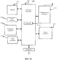
- FIG. 15 illustrates a block diagram of an apparatus for data transmission according to an example.
- the apparatus 1500 for data transmission is applied to a sending device.
- the apparatus 1500 for data transmission may include one or more of the following components: a processing component 1502, a memory 1504, a power component 1506, a multimedia component 1508, an audio component 1510, an input/output (I/O) interface 1512, a sensor component 1514, and a communication component 1516.
- the processing component 1502 typically controls overall operations of the apparatus 1500 for data transmission, such as the operations associated with display, telephone calls, data communications, camera operations, and recording operations.
- the processing component 1502 may include one or more processors 1520 to execute instructions to perform all or part of the steps in the abovementioned method.
- the processing component 1502 may include one or more modules which facilitate interaction between the processing component 1502 and the other components.
- the processing component 1502 may include a multimedia module to facilitate interaction between the multimedia component 1508 and the processing component 1502.
- the memory 1504 is configured to store various types of data to support the operation of the apparatus 1500 for data transmission. Examples of such data include instructions for any applications or methods operated on the apparatus 1500 for data transmission, contact data, phonebook data, messages, pictures, video, etc.
- the memory 1504 may be implemented by any type of volatile or non-volatile memory devices, or a combination thereof, such as a Static Random Access Memory (SRAM), an Electrically Erasable Programmable Read-Only Memory (EEPROM), an Erasable Programmable Read-Only Memory (EPROM), a Programmable Read-Only Memory (PROM), a Read-Only Memory (ROM), a magnetic memory, a flash memory, and a magnetic or optical disk.
- SRAM Static Random Access Memory
- EEPROM Electrically Erasable Programmable Read-Only Memory
- EPROM Erasable Programmable Read-Only Memory
- PROM Programmable Read-Only Memory
- ROM Read-Only Memory
- magnetic memory a magnetic memory
- flash memory and a magnetic
- the power component 1506 provides power for various components of the apparatus 1500 for data transmission.
- the power component 1506 may include a power management system, one or more power supplies, and other components associated with generation, management and distribution of power for the apparatus 1500 for data transmission.
- the multimedia component 1508 includes a screen providing an output interface between the apparatus 1500 for data transmission and a user.
- the screen may include a Liquid Crystal Display (LCD) and a Touch Panel (TP). If the screen includes the TP, the screen may be implemented as a touch screen to receive input signals from the user.
- the TP includes one or more touch sensors to sense touches, swipes, and gestures on the TP. The touch sensors may not only sense a boundary of a touch or swipe action, but also sense a duration and pressure associated with the touch or swipe action.
- the multimedia component 1508 includes a front camera and/or a rear camera.
- the front camera and/or the rear camera may receive external multimedia data when the apparatus 1500 for data transmission is in an operating mode, such as a photographing mode or a video mode.
- an operating mode such as a photographing mode or a video mode.
- Each of the front camera and the rear camera may be a fixed optical lens system or have focusing and optical zooming capabilities.
- the audio component 1510 is configured to output and/or input an audio signal.
- the audio component 1510 includes a Microphone (MIC), and the MIC is configured to receive an external audio signal when the apparatus 1500 for data transmission is in the operating mode, such as a call mode, a recording mode and a voice recognition mode.
- the received audio signal may be further stored in the memory 1504 or sent through the communication component 1516.
- the audio component 1510 further includes a speaker configured to output the audio signal.
- the I/O interface 1512 provides an interface between the processing component 1502 and a peripheral interface module, and the peripheral interface module may be a keyboard, a click wheel, a button and the like.
- the button may include, but not limited to: a home button, a volume button, a start button and a lock button.
- the sensor component 1514 includes one or more sensors configured to provide status assessment in various aspects for the apparatus 1500 for data transmission. For instance, the sensor component 1514 may detect an on/off status of the apparatus 1500 for data transmission and relative positioning of components, such as a display and small keyboard of the apparatus 1500 for data transmission, and the sensor component 1514 may further detect a change in a position of the apparatus 1500 for data transmission or a component of the apparatus 1500 for data transmission, presence or absence of contact between the user and the apparatus 1500 for data transmission, orientation or acceleration/deceleration of the apparatus 1500 for data transmission and a change in temperature of the apparatus 1500 for data transmission.
- the sensor component 1514 may include a proximity sensor configured to detect presence of an object nearby without any physical contact.
- the sensor component 1514 may also include a light sensor, such as a Complementary Metal Oxide Semiconductor (CMOS) or Charge Coupled Device (CCD) image sensor, configured for use in an imaging application.
- CMOS Complementary Metal Oxide Semiconductor
- CCD Charge Coupled Device
- the sensor component 1514 may also include an acceleration sensor, a gyroscope sensor, a magnetic sensor, a pressure sensor or a temperature sensor.
- the communication component 1516 is configured to facilitate wired or wireless communication between the apparatus 1500 for data transmission and another device.
- the apparatus 1500 for data transmission may access a communication standard based wireless network, such as Wireless Fidelity (WiFi), 2nd-Generation (2G), 3G, 4G, 5G, or a combination thereof, or an intercom network.
- the communication component 1516 receives a broadcast signal or broadcast associated information from an external broadcast management system through a broadcast channel.
- the communication component 1516 further includes a Near Field Communication (NFC) module to facilitate short-range communication.
- the NFC module may be implemented based on a Radio Frequency Identification (RFID) technology, an Infrared Data Association (IrDA) technology, an Ultra Wide Band (UWB) technology, a Bluetooth (BT) technology and another technology.
- RFID Radio Frequency Identification
- IrDA Infrared Data Association
- UWB Ultra Wide Band
- BT Bluetooth
- the apparatus 1500 for data transmission may be implemented by one or more Application Specific Integrated Circuits (ASICs), Digital Signal Processors (DSPs), Digital Signal Processing Devices (DSPDs), Programmable Logic Devices (PLDs), Field Programmable Gate Arrays (FPGAs), controllers, micro-controllers, microprocessors or other electronic components, and is configured to execute the abovementioned method.
- ASICs Application Specific Integrated Circuits
- DSPs Digital Signal Processors
- DSPDs Digital Signal Processing Devices
- PLDs Programmable Logic Devices
- FPGAs Field Programmable Gate Arrays
- controllers micro-controllers, microprocessors or other electronic components, and is configured to execute the abovementioned method.
- non-transitory computer-readable storage medium including instructions, such as the memory 1504 including instructions, and the instructions may be executed by the processor 1520 of the apparatus 1500 for data transmission to implement the abovementioned method.
- the non-transitory computer-readable storage medium may be a ROM, a Random Access Memory (RAM), a Compact Disc Read-Only Memory (CD-ROM), a magnetic tape, a floppy disc, an optical data storage device and the like.
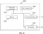
- FIG. 16 illustrates a block diagram of an apparatus for data transmission according to an example.
- the apparatus 1600 for data transmission may be provided as a server.
- the apparatus 1600 for data transmission includes a processing component 1602, further including one or more processors, and includes a memory resource represented by a memory 1603.
- the memory is configured to store instructions executable for the processing component 1602, for example, an application program.
- the application program stored in the memory 1603 may include one or more modules of which each corresponds to a set of instructions.
- the processing component 1602 is configured to execute the instructions to execute the abovementioned method.
- the apparatus 1600 for data transmission may further include a power component 1606 configured to execute power management of the apparatus 1600 for data transmission, a wired or wireless network interface 1605 configured to connect the apparatus 1600 for data transmission to a network, and an I/O interface 1608.
- the apparatus 1600 for data transmission may be operated based on an operating system stored in the memory 1603, for example, Windows ServerTM, Max OS XTM, UnixTM, LinuxTM, FreeBSDTM, or the like.
- the non-transitory computer-readable storage medium may be a ROM, a RAM, a CD-ROM, a magnetic tape, a floppy disk, and an optical data storage device.
- the apparatus 1500 for data transmission or the apparatus 1600 for data transmission is enabled to execute the following method.
- the method including that: during performing resource mapping of data to be transmitted onto a first symbol of an available transmission resource, a first subcarrier spacing, at least one target subcarrier, a number of inverse fast fourier transform (IFFT) points and a zero-setting length for the first symbol of the available transmission resource are determined according to a carrier spacing configuration factor and a second subcarrier spacing for a second symbol of the available transmission resource; the data to be transmitted is mapped, in a frequency domain, to each of the at least one target subcarrier; the data to be transmitted is modulated according to each of the at least one target subcarrier and the number of IFFT points to obtain a time-domain symbol; foremost information of the zero-setting length in the time-domain symbol is set to 0 to obtain an output symbol; and the output symbol is transmitted.
- IFFT inverse fast fourier transform
- the operation that the first subcarrier spacing, the at least one target subcarrier, the number of inverse fast fourier transform (IFFT) points and the zero-setting length for the first symbol of the available transmission resource are determined according to the carrier spacing configuration factor and the second subcarrier spacing for the second symbol of the available transmission resource include the following.
- T2 is the second subcarrier spacing for the second symbol of the available transmission resource, and n is the carrier spacing configuration factor.
- Each of the at least one target subcarrier is determined in the frequency domain of the first symbol of the available transmission resource according to the first subcarrier spacing for the first symbol of the available transmission resource.
- the carrier spacing configuration factor is equal to 1 in response to that a carrier frequency band of the available transmission resource is greater than 6GHz; or a value of the carrier spacing configuration factor includes 1, 2, or 3 in response to that the carrier frequency band of the available transmission resource is less than 6GHz.
- the method further includes one of following acts: receiving a first control signaling from a network access device, and parsing the first control signaling to obtain the carrier spacing configuration factor; receiving a second control signaling from a cluster header device in a cluster to which the sending device belongs, and parsing the second control signaling to obtain the carrier spacing configuration factor; or determining the carrier spacing configuration factor according to a processing capability of the sending device.
- the method further includes: sending a third control signaling to a receiving device, the third control signaling including the carrier spacing configuration factor.
Landscapes
- Engineering & Computer Science (AREA)
- Signal Processing (AREA)
- Computer Networks & Wireless Communication (AREA)
- Physics & Mathematics (AREA)
- Mathematical Physics (AREA)
- Discrete Mathematics (AREA)
- General Physics & Mathematics (AREA)
- Mobile Radio Communication Systems (AREA)
Abstract
Description
- The present invention relates to the technical field of communication, and more particularly, to a data transmission method and apparatus.
- Vehicle to Everything (V2X) refers to a new-generation information communication technology for connecting vehicles to everything. V2X includes Vehicle to Vehicle (V2V), Vehicle to Pedestrian (V2P), and Vehicle to Infrastructure (V2I). Cellular based V2X (C-V2X) is a wireless communication technology for vehicles formed based on such as a 3rd-Generation (3G)/4th-Generation (4G)/5th-Generation (5G) cellular communication technology, and usually includes two types of communication interfaces: one is short-distance direct communication interface (PC5) between a vehicle, a pedestrian and an infrastructure, and the other is a cellular communication interface (Uu) capable of implementing long-distance reliable communication of a larger range. A communication standard for the PC5 interface in V2X is based on Device to Device (D2D), and a broadcast communication manner is used, namely information is sent by broadcasting to multiple vehicles from a single vehicle.
- In the related art, in a Long Term Evolution (LTE) V2X communication technology, a subcarrier spacing is fixed to be 15KHz, and scheduling is performed in a unit of subframe. The length of a subframe is 1ms, and a subframe includes 14 symbols. During rate matching for data, the number of bits that can be borne is calculated according to loads of the 14 symbols. However, during mapping from a logical channel to a physical channel, considering interferences of a base station to uplink/downlink data, a Guard Period (GP) is introduced, namely no data is practically sent on the last symbol of each subframe, making it impossible for a receiving device to obtain useful information of at least one symbol, reducing the decoding performance and affecting the quality of service and the system performance.
- Examples of the invention provide a method and apparatus for data transmission. The technical solutions are implemented as follows.
- According to a first aspect of the invention, a method for data transmission method is provided, applied to a sending device and including: during performing resource mapping of data to be transmitted onto a first symbol of an available transmission resource, determining a first subcarrier spacing, at least one target subcarrier, a number of inverse fast fourier transform (IFFT) points and a zero-setting length for the first symbol of the available transmission resource, according to a carrier spacing configuration factor and a second subcarrier spacing for a second symbol of the available transmission resource; mapping, in a frequency domain, the data to be transmitted to each of the at least one target subcarrier; modulating the data to be transmitted according to each of the at least one target subcarrier and the number of IFFT points to obtain a time-domain symbol; setting foremost information of the zero-setting length in the time-domain symbol to 0 to obtain an output symbol; and transmitting the output symbol.
- In the method for data transmission provided in the examples of the invention, during performing resource mapping of the data to be transmitted onto the first symbol of the available transmission resource, resource mapping is performed in the frequency domain using the first subcarrier spacing determined based on the carrier spacing configuration factor, and the foremost information of the zero-setting length in the time-domain symbol obtained by modulation is set to 0. When receiving the output symbol from the sending device, a receiving device does not process or perform statistics on the foremost information of the zero-setting length in the output symbol, and instead, modulates and processes remaining information in the output symbol except the zero-setting length to obtain the data to be transmitted, so that a function as GP is realized. Since a last symbol of each subframe contains information, the problem in the related art that the receiving device loses useful information of at least one symbol because no data is sent on the last symbol can be solved. The decoding performance can be improved, and the quality of service and the system performance can be improved.
- In an example, the operation of determining the first subcarrier spacing, the at least one target subcarrier, the number of inverse fast fourier transform (IFFT) points and the zero-setting length for the first symbol of the available transmission resource, according to the carrier spacing configuration factor and the second subcarrier spacing for the second symbol of the available transmission resource includes: calculating, based on a formula T1=T2*2n, the first subcarrier spacing T1 for the first symbol of the available transmission resource, wherein T2 is the second subcarrier spacing for the second symbol of the available transmission resource, and n is the carrier spacing configuration factor; determining each of the at least one target subcarrier in the frequency domain of the first symbol of the available transmission resource according to the first subcarrier spacing for the first symbol of the available transmission resource; calculating, based on a formula N1=N2/2n, the number of IFFT points N1 for the first symbol of the available transmission resource according to a number of IFFT points N2 for the second symbol of the available transmission resource; and calculating, based on a formula L0=1-1/2n, the zero-setting length L0.
- In an example, the carrier spacing configuration factor is equal to 1 in response to that a carrier frequency band of the available transmission resource is greater than 6GHz; or, a value of the carrier spacing configuration factor includes 1, 2, or 3 in response to that the carrier frequency band of the available transmission resource is less than 6GHz.
- In an example, the method further includes one of following acts: receiving a first control signaling from a network access device, and parsing the first control signaling to obtain the carrier spacing configuration factor; receiving a second control signaling from a cluster header device in a cluster to which the sending device belongs, and parsing the second control signaling to obtain the carrier spacing configuration factor; or determining the carrier spacing configuration factor according to a processing capability of the sending device.
- In an example, the method further includes: sending a third control signaling to a receiving device, the third control signaling including the carrier spacing configuration factor.
- According to a second aspect of the invention, a method for data transmission is provided, applied to a receiving device and including: determining a first subcarrier spacing, a number of fast fourier transform (FFT) points and a zero-setting length for a first symbol of an available transmission resource of a sending device according to a carrier spacing configuration factor; and in response to receiving an output symbol from the sending device, determining data to be transmitted according to the carrier spacing configuration factor, the number of FFT points and remaining information in the output symbol except the zero-setting length.
- In an example, the method further includes one of following acts: receiving a third control signaling from the sending device, and parsing the third control signaling to obtain the carrier spacing configuration factor; receiving a fourth control signaling from a network access device, and parsing the fourth control signaling to obtain the carrier spacing configuration factor; or receiving a fifth control signaling from a cluster header device in a cluster to which the receiving device belongs, and parsing the fifth control signaling to obtain the carrier spacing configuration factor.
- In an example, the operation of determining the first subcarrier spacing, the number of fast fourier transform (FFT) points and the zero-setting length for the first symbol of the available transmission resource of the sending device according to the carrier spacing configuration factor includes: calculating, based on a formula T1=T2*2n, the first subcarrier spacing T1 for the first symbol of the available transmission resource of the sending device, wherein T2 is a second subcarrier spacing for a second symbol of the available transmission resource of the sending device, and n is the carrier spacing configuration factor; calculating, based on a formula N3=N4/2n, the number of FFT points N3 for the first symbol of the available transmission resource of the sending device according to a number of FFT points N4 for the second symbol of the available transmission resource of the sending device; and calculating, based on a formula L0=1-1/2n, the zero-setting length L0.
- According to a third aspect of the invention, an apparatus for data transmission is provided, including: a first determination module, configured to: during performing resource mapping of data to be transmitted onto a first symbol of an available transmission resource, determine a first subcarrier spacing, at least one target subcarrier, a number of inverse fast fourier transform (IFFT) points and a zero-setting length for the first symbol of the available transmission resource, according to a carrier spacing configuration factor and a second subcarrier spacing for a second symbol of the available transmission resource; a mapping module, configured to map, in a frequency domain, the data to be transmitted to each of the at least one target subcarrier; a modulation module, configured to modulate the data to be transmitted according to each of the at least one target subcarrier and the number of IFFT points to obtain a time-domain symbol; a processing module, configured to set foremost information of the zero-setting length in the time-domain symbol to 0 to obtain an output symbol; and a transmitting module, configured to transmit the output symbol.
- In an example, the first determination module includes: a first calculation submodule, configured to calculate, based on a formula T1=T2*2n, the first subcarrier spacing T1 for the first symbol of the available transmission resource, wherein T2 is the second subcarrier spacing for the second symbol of the available transmission resource, and n is the carrier spacing configuration factor; a determination submodule, configured to determine each of the at least one target subcarrier in the frequency domain of the first symbol of the available transmission resource according to the first subcarrier spacing for the first symbol of the available transmission resource; a second calculation submodule, configured to calculate, based on a formula N1=N2/2n, the number of IFFT points N1 for the first symbol of the available transmission resource according to a number of IFFT points N2 for the second symbol of the available transmission resource; and a third calculation submodule, configured to calculate, based on a formula L0=1-1/2°, the zero-setting length L0.
- In an example, the carrier spacing configuration factor is equal to 1 in response to that a carrier frequency band of the available transmission resource is greater than 6GHz; or a value of the carrier spacing configuration factor includes 1, 2, or 3 in response to that the carrier frequency band of the available transmission resource is less than 6GHz.
- In an example, the apparatus may further include one of following: a first receiving module, configured to receive a first control signaling from a network access device, and parse the first control signaling to obtain the carrier spacing configuration factor; a second receiving module, configured to receive a second control signaling from a cluster header device in a cluster to which the sending device belongs, and parse the second control signaling to obtain the carrier spacing configuration factor; or a second determination module, configured to determine the carrier spacing configuration factor according to a processing capability of the sending device.
- In an example, the apparatus may further include: a sending module, configured to send a third control signaling to a receiving device, the third control signaling including the carrier spacing configuration factor.
- According to a fourth aspect of the invention, an apparatus for data transmission apparatus is provided, including: a third determination module, configured to determine a first subcarrier spacing, a number of fast fourier transform (FFT) points and a zero-setting length for a first symbol of an available transmission resource of a sending device according to a carrier spacing configuration factor; and a fourth determination module, configured to: in response to receiving an output symbol from the sending device, determine data to be transmitted according to the carrier spacing configuration factor, the number of FFT points and remaining information in the output symbol except the zero-setting length.
- In an example, the apparatus may further include one of following: a third receiving module, configured to receive a third control signaling from the sending device, and parsing the third control signaling to obtain the carrier spacing configuration factor; a fourth receiving module, configured to receive a fourth control signaling from a network access device, and parsing the fourth control signaling to obtain the carrier spacing configuration factor; or a fifth receiving module, configured to receive a fifth control signaling from a cluster header device in a cluster to which the receiving device belongs, and parsing the fifth control signaling to obtain the carrier spacing configuration factor.
- In an example, the third determination module is further configured to: calculate, based on a formula T1=T2*2n, the first subcarrier spacing T1 for the first symbol of the available transmission resource of the sending device, wherein T2 is a second subcarrier spacing for a second symbol of the available transmission resource of the sending device, and n is the carrier spacing configuration factor; calculate, based on a formula N3=N4/2n, the number of FFT points N3 for the first symbol of the available transmission resource of the sending device according to a number of FFT points N4 for the second symbol of the available transmission resource of the sending device; and calculate, based on a formula L0=1-1/2n, the zero-setting length L0.
- According to a fifth aspect of the invention, an apparatus for data transmission is provided, including: a processor; and a memory configured to store instructions executable for the processor, wherein the processor may be configured to: during performing resource mapping of data to be transmitted onto a first symbol of an available transmission resource, determine a first subcarrier spacing, at least one target subcarrier, a number of inverse fast fourier transform (IFFT) points and a zero-setting length for the first symbol of the available transmission resource, according to a carrier spacing configuration factor and a second subcarrier spacing for a second symbol of the available transmission resource; map, in a frequency domain, the data to be transmitted to each of the at least one target subcarrier; modulate the data to be transmitted according to each of the at least one target subcarrier and the number of IFFT points to obtain a time-domain symbol; set foremost information of the zero-setting length in the time-domain symbol to 0 to obtain an output symbol; and transmit the output symbol.
- According to a sixth aspect of the invention, an apparatus for data transmission is provided, including: a processor; and a memory configured to store instructions executable for the processor, wherein the processor is configured to: determine a first subcarrier spacing, a number of fast fourier transform (FFT) points and a zero-setting length for a first symbol of an available transmission resource of a sending device according to a carrier spacing configuration factor; and in response to receiving an output symbol from the sending device, determine data to be transmitted according to the carrier spacing configuration factor, the number of FFT points and remaining information in the output symbol except the zero-setting length.
- According to a seventh aspect of the invention, a computer-readable storage medium is provided, having stored thereon computer instructions which, when executed by a processor, implement the steps of the method as described in the first aspect.
- According to an eighth aspect of the invention, a computer-readable storage medium is provided, having stored thereon computer instructions which, when executed by a processor, implement the steps of the method as described in the second aspect.
- It should be understood that the above general descriptions and detailed descriptions below are only exemplary and explanatory and are not intended to limit the invention.
- The accompanying drawings, which are incorporated in and constitute a part of this specification, illustrate examples consistent with the invention and, together with the description, serve to explain the principles of the invention.
-
FIG. 1 illustrates a flow chart of a data transmission method according to an example. -
FIG. 2 illustrates a flow chart of a data transmission method according to an example. -
FIG. 3 illustrates a flow chart of a data transmission method according to an example. -
FIG. 4 illustrates a schematic diagram of frequency-domain resource mapping on a first symbol according to an example. -
FIG. 5 illustrates a schematic diagram of frequency-domain resource mapping on a first symbol according to an example. -
FIG. 6 illustrates a schematic diagram of frequency-domain resource mapping on a first symbol according to an example. -
FIG. 7 illustrates a block diagram of an apparatus for data transmission according to an example. -
FIG. 8 illustrates a block diagram of an apparatus for data transmission according to an example. -
FIG. 9A illustrates a block diagram of an apparatus for data transmission according to an example. -
FIG. 9B illustrates a block diagram of an apparatus for data transmission according to an example. -
FIG. 9C illustrates a block diagram of an apparatus for data transmission according to an example. -
FIG. 10 illustrates a block diagram of an apparatus for data transmission according to an example. -
FIG. 11 illustrates a block diagram of an apparatus for data transmission according to an example. -
FIG. 12A illustrates a block diagram of an apparatus for data transmission according to an example. -
FIG. 12B is a block diagram of a data transmission apparatus, according to an example. -
FIG. 12C illustrates a block diagram of an apparatus for data transmission according to an example. -
FIG. 13 illustrates a block diagram of an apparatus for data transmission according to an example. -
FIG. 14 illustrates a block diagram of an apparatus for data transmission according to an example. -
FIG. 15 illustrates a block diagram of an apparatus for data transmission according to an example. -
FIG. 16 illustrates a block diagram of an apparatus for data transmission according to an example. - Reference will now be made in detail to embodiments, examples of which are illustrated in the accompanying drawings. The following description refers to the accompanying drawings in which the same numbers in different drawings represent the same or similar elements unless otherwise represented. The implementations set forth in the following description of embodiments do not represent all implementations consistent with the invention. Instead, they are merely examples of apparatuses and methods consistent with aspects related to the invention as recited in the appended claims.
- The examples of the invention provide a method for data transmission, which is applied to a sending device. The method includes the following. During performing resource mapping of data to be transmitted onto a first symbol of an available transmission resource, a first subcarrier spacing, at least one target subcarrier, a number of IFFT points and a zero-setting length for the first symbol of the available transmission resource are determined according to a carrier spacing configuration factor and a second subcarrier spacing for a second symbol of the available transmission resource. The data to be transmitted is mapped to each of the at least one target subcarrier in a frequency domain. The data to be transmitted is modulated according to each of the at least one target subcarrier and the number of IFFT points to obtain a time-domain symbol. Foremost information of the zero-setting length in the time-domain symbol is set to 0 to obtain an output symbol. The output symbol is transmitted.
- In the method for data transmission provided in the examples of the invention, during performing resource mapping of the data to be transmitted onto the first symbol of the available transmission resource, resource mapping is performed in the frequency domain using the first subcarrier spacing determined based on the carrier spacing configuration factor, and the foremost information of the zero-setting length in the time-domain symbol obtained by modulation is set to 0. When receiving the output symbol from the sending device, a receiving device does not process or perform statistics on the foremost information of the zero-setting length in the output symbol, and instead, modulates and processes remaining information in the output symbol except the zero-setting length to obtain the data to be transmitted, so that a function as GP is realized. Since a last symbol of each subframe contains information, the problem in the related art that the receiving device loses useful information of at least one symbol because no data is sent on the last symbol can be solved. The decoding performance can be improved, and the quality of service and the system performance can be improved.
- It is to be noted that the method for data transmission provided in the examples of the invention may be applied to a 4G/5G-based C-V2X communication network. The sending device and receiving device involved in the invention may include, for example, a device like a vehicle-mounted device, a road-side unit, or a handheld device. The handheld device may include for example an electronic device like a smart phone, a notebook computer, or an intelligent wearable device. A network access device involved in the invention may include for example a communication device that provides wireless access service for a terminal, like a base station or a relay station.
- Based on the above analysis, the following particular examples are proposed.
-
FIG. 1 illustrates a flow chart of a method for data transmission according to an example. An execution body of the method for data transmission may be a sending device. As illustrated inFIG. 1 , the method includes the followingSteps 101 to 105. - In
Step 101, during performing resource mapping of data to be transmitted onto a first symbol of an available transmission resource, a first subcarrier spacing, at least one target subcarrier, a number of IFFT points and a zero-setting length for the first symbol of the available transmission resource are determined according to a carrier spacing configuration factor and a second subcarrier spacing for a second symbol of the available transmission resource. - Exemplarily, the data to be transmitted may include user data or a pilot signal. The available transmission resource refers to time-domain, frequency-domain, space-domain and code-domain practical physical transmission resources allocated to the sending device. The first symbol of the available transmission resource may be a first symbol sent by the sending device, or may be a first symbol in a time slot. The second subcarrier spacing for the second symbol of the available transmission resource may be a subcarrier spacing designated by a network access device upon resource allocation.
- Exemplarily, an implementation of the operation that the sending device pre-obtains the carrier spacing configuration factor may include any one or combination of the following modes.
- Mode 1: the network access device determines the carrier spacing configuration factor according to a coverage radius. The network access device sends first control signaling to the sending device, the first control signaling including the carrier spacing configuration factor. The sending device receives the first control signaling from the network access device, and parses the first control signaling to obtain the carrier spacing configuration factor. Optionally, the carrier spacing configuration factor is represented by a preset bit in the first control signaling.
- Mode 2: a cluster header device in a cluster to which the sending device belongs determines the carrier spacing configuration factor according to a transmission distance. The cluster header device sends a second control signaling to the sending device, the second control signaling including the carrier spacing configuration factor. The sending device receives the second control signaling from the cluster header device in the cluster to which the sending device belongs, and parses the second control signaling to obtain the carrier spacing configuration factor. Optionally, the carrier spacing configuration factor is represented by a preset bit in the second control signaling.
Exemplarily, if the sending device belongs to a cluster, the cluster header device in the cluster may determine the carrier spacing configuration factor according to the transmission distance, and notify the sending device of the carrier spacing configuration factor through the second control signaling. For example, the cluster may be a network composed of multiple devices, and the cluster header device may be a centralized control device selected from the multiple devices. - Mode 3: the sending device determines the carrier spacing configuration factor according to a processing capability of the sending device.
- Optionally, the sending device may send a third control signaling to a receiving device after determining the carrier spacing configuration factor. The third control signaling includes the carrier spacing configuration factor. Optionally, the carrier spacing configuration factor is represented by a preset bit in the third control signaling.
- In
Step 102, the data to be transmitted is mapped to each of the at least one target subcarrier in a frequency domain. - In
Step 103, the data to be transmitted is modulated according to each of the at least one target subcarrier and the number of IFFT points to obtain a time-domain symbol. - For example, Orthogonal Frequency Division Multiplexing (OFDM) modulation is performed on the data to be transmitted according to each of the at least one target subcarrier and the number of IFFT points to obtain the time-domain symbol.
- In
Step 104, foremost information of the zero-setting length in the time-domain symbol is set to 0 to obtain an output symbol. - Exemplarily, after the time-domain symbol is obtained by modulation, foremost bits of the zero-setting length in the first symbol of the time-domain symbol are set to 0, and zero-setting processing is not performed on any other symbol.
- In
Step 105, the output symbol is transmitted. - Exemplarily, when receiving the output symbol from the sending device, the receiving device does not process or perform statistics on the foremost information of the zero-setting length in the output symbol, and instead, demodulates and processes remaining information in the output symbol except the zero-setting length to obtain the data to be transmitted.
- By means of the technical solution provided in the example of the invention, during performing resource mapping of the data to be transmitted onto the first symbol of the available transmission resource, resource mapping is performed in the frequency domain using the first subcarrier spacing determined based on the carrier spacing configuration factor, and the foremost information of the zero-setting length in the time-domain symbol obtained by modulation is set to 0. When receiving the output symbol from the sending device, a receiving device does not process or perform statistics on the foremost information of the zero-setting length in the output symbol, and instead, modulates and processes remaining information in the output symbol except the zero-setting length to obtain the data to be transmitted, so that a function as GP is realized. Since a last symbol of each subframe contains information, the problem in the related art that the receiving device loses useful information of at least one symbol because no data is sent on the last symbol can be solved. The decoding performance can be improved, and the quality of service and the system performance can be improved.
- In an example, an implementation of the operation that the first subcarrier spacing, the at least one target subcarrier, the number of IFFT points and the zero-setting length for the first symbol of the available transmission resource are determined according to the carrier spacing configuration factor and the second subcarrier spacing for the second symbol of the available transmission resource may include that:
- After the carrier spacing configuration factor and the second subcarrier spacing T2 for the second symbol of the available transmission resource are obtained, the first subcarrier spacing T1 for the first symbol of the available transmission resource is calculated based on a formula T1=T2*2n. T2 is the second subcarrier spacing for the second symbol of the available transmission resource, and n is the carrier spacing configuration factor. Each of the at least one target subcarrier is determined in the frequency domain of the first symbol of the available transmission resource according to the first subcarrier spacing for the first symbol of the available transmission resource. The number of IFFT points N1 for the first symbol of the available transmission resource is calculated based on a formula N1=N2/2n according to a number of IFFT points N2 for the second symbol of the available transmission resource. The zero-setting length L0 is calculated based on a formula L0=1-1/2n.
- During particular implementation, the numerical value 2 in T1=T2*2n may be set in a protocol. Specifically, the calculation formula T1=T2*2n including the numerical value 2 may be set in codes executable for a processor of a terminal or the network access device.
- In an example, based on present frequency spectrum planning, the carrier spacing configuration factor is equal to 1 when a carrier frequency band of the available transmission resource is greater than 6GHz; or, a value of the carrier spacing configuration factor may include 1, 2, or 3 when the carrier frequency band of the available transmission resource is less than 6GHz.
- According to the present frequency spectrum planning, subcarrier spacings 60khz and 120khz may be scheduled by a system when the carrier frequency band is greater than 6GHz. Namely there is a double relationship only, and correspondingly, n is 1. Subcarrier spacings 15khz, 30khz, 60khz, and 120khz may be scheduled by the system when the carrier frequency band is below 6GHz. Namely there are double, quadruple and octuple relationships only, and correspondingly, n is 1, 2, or 3.
- Exemplarily, when a value of the carrier spacing configuration factor may include 1, 2, or 3, the carrier spacing configuration factor may be represented by 2 bits. For example, '00' represents that the carrier spacing configuration factor is 1, '01' represents that the carrier spacing configuration factor is 2, and '11' represents that the carrier spacing configuration factor is 3.
-
FIG. 2 illustrates a flow chart of a method for data transmission according to an example. An execution body of the method for data transmission may be a receiving device. As illustrated inFIG. 2 , the method includes the followingSteps 201 to 202. - In
Step 201, a first subcarrier spacing, a number of FFT points and a zero-setting length for a first symbol of an available transmission resource of a sending device are determined according to a carrier spacing configuration factor. - Exemplarily, an implementation of the operation that the receiving device pre-obtains the carrier spacing configuration factor may include any one or combination of the following modes.
- Mode a: the sending device determines the carrier spacing configuration factor according to a processing capability of the sending device, and sends a third control signaling to the receiving device. The third control signaling includes the carrier spacing configuration factor. The receiving device receives the third control signaling from the sending device, and parses the third control signaling to obtain the carrier spacing configuration factor.
- Mode b: a network access device determines the carrier spacing configuration factor according to a coverage radius. The network access device sends a fourth control signaling to the receiving device. The fourth control signaling includes the carrier spacing configuration factor. The receiving device receives the fourth control signaling from the network access device, and parses the fourth control signaling to obtain the carrier spacing configuration factor.
- Mode c: a cluster header device in a cluster to which the sending device belongs determines the carrier spacing configuration factor according to a transmission distance, and sends a fifth control signaling to the receiving device. The fifth control signaling includes the carrier spacing configuration factor. The receiving device receives the fifth control signaling from the cluster header device in the cluster to which the sending device belongs, and parses the fifth control signaling to obtain the carrier spacing configuration factor.
- In
Step 202, in response to receiving an output symbol from the sending device, data to be transmitted is determined according to the carrier spacing configuration factor, the number of FFT points and remaining information in the output symbol except the zero-setting length. - By means of the technical solution provided in the examples of the invention, the carrier spacing configuration factor corresponding to the sending device is pre-obtained. When receiving the output symbol from the sending device, the receiving device does not process or perform statistics on the foremost information of the zero-setting length in the output symbol, and instead, modulates and processes remaining information in the output symbol except the zero-setting length, to obtain the data to be transmitted, so that a function as GP is realized. Since a last symbol of each subframe contains information, the problem in the related art that the receiving device loses useful information of at least one symbol because no data is sent on the last symbol can be solved. The decoding performance can be improved, and thus the quality of service and the system performance can be improved.
- In an example, the operation in the abovementioned example that the first subcarrier spacing, the number of FFT points and the zero-setting length for the first symbol of the available transmission resource of the sending device are determined according to the carrier spacing configuration factor may include that:
By the formula T1=T2*2n, the first subcarrier spacing T1 for the first symbol of the available transmission resource of the sending device is calculated. T2 is a second subcarrier spacing for a second symbol of the available transmission resource of the sending device, and n is the carrier spacing configuration factor. By the formula N3=N4/2n, the number of FFT points N3 for the first symbol of the available transmission resource of the sending device is calculated according to a number of FFT points N4 for the second symbol of the available transmission resource of the sending device. The zero-setting length L0 is calculated based on a formula L0=1-1/2n. -
FIG. 3 illustrates a flow chart of a method for data transmission according to an example. A sending device and receiving device in a 4G/5G-based C-V2X communication network cooperate to implement the method. As illustrated inFIG. 3 , based on the examples illustrated inFIG. 1 and FIG. 2 , the method for data transmission involved in the invention may include the following Steps 301 to 307. - In Step 301, the sending device obtains a carrier spacing configuration factor.
- In Step 302, during performing resource mapping of data to be transmitted onto a first symbol of an available transmission resource, the sending device determines a first subcarrier spacing, at least one target subcarrier, a number of IFFT points and a zero-setting length for the first symbol of the available transmission resource according to the carrier spacing configuration factor and a second subcarrier spacing for a second symbol of the available transmission resource.
- In
Step 303, the sending device maps the data to be transmitted to each of the at least one target subcarrier in a frequency domain. - In
Step 304, the sending device modulates the data to be transmitted according to each of the at least one target subcarrier and the number of IFFT points to obtain a time-domain symbol. - In
Step 305, the sending device sets foremost information of the zero-setting length in the time-domain symbol to 0 to obtain an output symbol. - In
Step 306, the sending device transmits the output symbol. - In Step 307, the receiving device determines the first subcarrier spacing, a number of FFT points and the zero-setting length for the first symbol of the available transmission resource of the sending device according to the carrier spacing configuration factor.
- In Step 308, when receiving the output symbol from the sending device, the receiving device determines the data to be transmitted according to the carrier spacing configuration factor, the number of FFT points and remaining information in the output symbol except the zero-setting length.
- Exemplarily, the receiving device does not make statistics on the foremost information of the zero-setting length in the first symbol in the output symbol, and performs analog signal reception and/or Automatic Gain Control (AGC) operation and processing on the remaining information in the first symbol in the output symbol except the zero-setting length, and the other symbols of the output symbol to obtain the data to be transmitted. The number of FFT points for the first symbol of the output symbol is 1/2n times the number of FFT points for the second symbol. The number of FFT points for the second symbol is designated by a network access device upon resource allocation.
- By means of the technical solution provided in the example of the invention, during performing resource mapping of the data to be transmitted onto the first symbol of the available transmission resource, the resource mapping is performed in the frequency domain using the first subcarrier spacing determined based on the carrier spacing configuration factor, and the foremost information of the zero-setting length in the time-domain symbol obtained by modulation is set to 0. When receiving the output symbol from the sending device, the receiving device does not process or perform statistics on the foremost information of the zero-setting length in the output symbol, and instead, modulates and processes the remaining information in the output symbol except the zero-setting length to obtain the data to be transmitted, so that a function as GP is realized. Since a last symbol of each subframe contains information, the problem in the related art that the receiving device loses useful information of at least one symbol because no data is sent on the last symbol can be solved. The decoding performance can be improved, and thus the quality of service and the system performance can be improved.
- In an example, a processing process of a physical layer in a mobile communication system may include the following steps.
- In Step 1), a Cyclic Redundancy Check (CRC) code is added to each transport block: for ensuring error detection of a channel, all data blocks sent by a Media Access Control (MAC) layer need to be added to a CRC code.
- In Step 2), code block segmentation, and addition of CRC information to code block segments: for ensuring that the size of a code block is not greater than a threshold, for example, 6,144 bits, the transport block needs to be segmented; and for ensuring that the receiving device can stop erroneous decoding in advance, the CRC information is further added to each code block.
- In Step 3), channel coding: a k-bit sequence is mapped to an m-bit sequence. The bits that have not been coded are referred to as original bits or source bits, and coded bits are referred to as codewords or codeword bits. Generally, m is more than or equal to k, and k/m is referred to as a code rate.
- In Step 4), rate matching is performed: it is judged whether a practically transmitted physical resource is matched with the coded bits or not. If the practically transmitted physical resource is greater than the number of the coded bits, the coded bits need to be duplicated to a certain extent according to a certain rule. If the practically transmitted physical resource is less than the number of the coded bits, part of coded bits need to be removed, to enable that a transmission capability is matched with the transmitted data. An example of a rate matching process is as follows: if physical bearers presently allocated to the sending device (user) are 2 Resource Blocks (RBs), 12 subcarriers and 14 symbols on each RB, a modulation mode is Quadrature Phase Shift Keying (QPSK) modulation, and a single-port antenna is used for transmission, then 2*12*14*2=672 physical bearers are available at present, the data to be transmitted includes 70 bits after being coded. In such a case, the 70 bits need to be duplicated to be 672 bits according to a certain rule.
- In Step 5), cascading of code blocks.
- In Step 6), channel interleaving: for avoiding the influence of selective fading of the channel on information, the data to be transmitted needs to be interleaved.
- In Step 7), mapping from a logical channel to a physical channel: during performing resource mapping of the data to be transmitted onto a first symbol of an available transmission resource, a first subcarrier spacing, at least one target subcarrier, a number of IFFT points and a zero-setting length for the first symbol of the available transmission resource are determined according to a carrier spacing configuration factor and a second subcarrier spacing for a second symbol of the available transmission resource. The data to be transmitted is mapped to each of the at least one target subcarrier in the frequency domain. A subcarrier spacing of the at least one target subcarrier is the first subcarrier spacing. The available transmission resource refers to time-domain, frequency-domain, space-domain and code-domain practical physical transmission resources allocated to the sending device. A value of the carrier spacing configuration factor n may be determined according to a carrier frequency band of the available transmission resource.
-
FIG. 4 to FIG. 6 illustrate schematic diagrams of frequency-domain resource mapping on a first symbol according to an example. There is made such a hypothesis that the carrier frequency band of the available transmission resource is less than 6GHz.FIG. 4 to FIG. 6 illustrate three different frequency-domain resource mapping manners respectively. - Referring to
FIG. 4 , the carrier spacing configuration factor n is equal to 1, and the first subcarrier spacing Δf2 for the first symbol (L=0) of the available transmission resource is 21 times, namely twice, of the second subcarrier spacing Δf1 for the second symbol (L=1) of the available transmission resource. - Referring to
FIG. 5 , the carrier spacing configuration factor n is equal to 2, and the first subcarrier spacing Δf3 for the first symbol (L=0) of the available transmission resource is 22 times, namely four times, of the second subcarrier spacing Δf1 for the second symbol (L=1) of the available transmission resource. - Referring to
FIG. 6 , the carrier spacing configuration factor n is equal to 3, and the first subcarrier spacing Δf4 for the first symbol (L=0) of the available transmission resource is 23 times, namely eight times, of the second subcarrier spacing Δf1 for the second symbol (L=1) of the available transmission resource. - In Step 8), OFDM modulation is performed, and a Cyclic Prefix (CP) is added: OFDM modulation is performed on the data to be transmitted according to each of the at least one target subcarrier and the number of IFFT points to obtain a time-domain symbol. During transformation to a time domain, the number of IFFT points for the first symbol is 1/2n times that for the second symbol. A foremost (1-1/2n) length of information in the time-domain symbol is set to 0 to obtain an output symbol.
- In Step 9), parallel-to-serial conversion: parallel-to-serial conversion is completed, and the output symbol is transmitted according to a time sequence.
- The receiving device pre-obtains a mapping manner for the first symbol of the available transmission resource of the sending device. The receiving device does not make statistics on the foremost (1-1/2n) length of information in the output symbol, and only performs analog signal reception and/or AGC operation and processing on remaining information in the first symbol in the output symbol except the foremost (1-1/2n) length of information and performs analog signal reception on other subsequently received symbols in the output symbol. A number of FFT points for the first symbol corresponding to the output symbol is 1/2n times that for the second symbol, thereby realizing a function as GP. Since a last symbol of each subframe contains information, the problem in the related art that the receiving device loses useful information of at least one symbol because no data is sent on the last symbol can be solved, and the decoding performance and the system performance can be improved.
- The below is an apparatus example of the invention, which may be used to execute the method example of the invention. Parts that are not described in detail in the apparatus example may refer to the method example.
-
FIG. 7 illustrates a block diagram of an apparatus for data transmission according to an example. The apparatus may be applied to a sending device. Referring toFIG. 7 , the apparatus for data transmission includes afirst determination module 701, amapping module 702, amodulation module 703, aprocessing module 704 and atransmitting module 705. - The
first determination module 701 is configured to: during performing resource mapping of data to be transmitted onto a first symbol of an available transmission resource, determine a first subcarrier spacing, at least one target subcarrier, a number of inverse fast fourier transform (IFFT) points and a zero-setting length for the first symbol of the available transmission resource, according to a carrier spacing configuration factor and a second subcarrier spacing for a second symbol of the available transmission resource. - The
mapping module 702 is configured to map, in a frequency domain, the data to be transmitted to each of the at least one target subcarrier. - The
modulation module 703 is configured to modulate the data to be transmitted according to each of the at least one target subcarrier and the number of IFFT points to obtain a time-domain symbol. - The
processing module 704 is configured to set foremost information of the zero-setting length in the time-domain symbol to 0 to obtain an output symbol. - The transmitting
module 705 is configured to transmit the output symbol. - By means of the apparatus provided in the example of the invention, during performing resource mapping of the data to be transmitted onto the first symbol of the available transmission resource, resource mapping is performed in the frequency domain using the first subcarrier spacing determined based on the carrier spacing configuration factor, and the foremost information of the zero-setting length in the time-domain symbol obtained by modulation is set to 0. When receiving the output symbol from the sending device, a receiving device does not process or perform statistics on the foremost information of the zero-setting length in the output symbol, and instead, modulates and processes remaining information in the output symbol except the zero-setting length to obtain the data to be transmitted, so that a function as GP is realized. Since a last symbol of each subframe contains information, the problem that the receiving device loses useful information of at least one symbol because no data is sent on the last symbol can be solved. The decoding performance can be improved, and the quality of service and the system performance can be improved.
- In an example, as illustrated in
FIG. 8 , in the apparatus for data transmission of inFIG. 7 , thefirst determination module 701 may be further configured to include afirst calculation submodule 801, adetermination submodule 802, asecond calculation submodule 803 and athird calculation submodule 804. - The
first calculation submodule 801 is configured to calculate, based on a formula T1=T2*2n, the first subcarrier spacing T1 for the first symbol of the available transmission resource. T2 is the second subcarrier spacing for the second symbol of the available transmission resource, and n is the carrier spacing configuration factor - The
determination submodule 802 is configured to determine each of the at least one target subcarrier in the frequency domain of the first symbol of the available transmission resource according to the first subcarrier spacing for the first symbol of the available transmission resource. - The
second calculation submodule 803 is configured to calculate, based on a formula N1=N2/2n, the number of IFFT points N1 for the first symbol of the available transmission resource according to a number of IFFT points N2 for the second symbol of the available transmission resource. - The
third calculation submodule 804 is configured to calculate, based on a formula L0=1-1/2n, the zero-setting length L0. - In an example, the carrier spacing configuration factor is equal to 1 in response to that a carrier frequency band of the available transmission resource is greater than 6GHz; or a value of the carrier spacing configuration factor includes 1, 2, or 3 in response to that the carrier frequency band of the available transmission resource is less than 6GHz.
- In an example, as illustrated in
FIG. 9A , the apparatus for data transmission of inFIG. 7 may further include afirst receiving module 901. Thefirst receiving module 901 is configured to receive a first control signaling sent by a network access device and parse the first control signaling to obtain the carrier spacing configuration factor. - In an example, as illustrated in
FIG. 9B , the apparatus for data transmission of inFIG. 7 may further include asecond receiving module 902. Thesecond receiving module 902 is configured to receive a second control signaling from a cluster header device in a cluster to which the sending device belongs, and parse the second control signaling to obtain the carrier spacing configuration factor. - In an example, as illustrated in
FIG. 9C , the apparatus for data transmission of inFIG. 7 may further include asecond determination module 903. Thesecond determination module 903 is configured to determine the carrier spacing configuration factor according to a processing capability of the sending device. - In an example, as illustrated in
FIG. 10 , the apparatus for data transmission of inFIG. 7 may further include asending module 1001. - The sending
module 1001 is configured to send a third control signaling to a receiving device. The third control signaling includes the carrier spacing configuration factor. -
FIG. 11 illustrates a block diagram of an apparatus for data transmission according to an example. The apparatus may be applied to a receiving device. Referring toFIG. 11 , the apparatus for data transmission includes athird determination module 1101 and afourth determination module 1102. - The
third determination module 1001 is configured to determine a first subcarrier spacing, a number of fast fourier transform (FFT) points and a zero-setting length for a first symbol of an available transmission resource of a sending device, according to a carrier spacing configuration factor. - The
fourth determination module 1102 is configured to: in response to receiving an output symbol from the sending device, determine data to be transmitted according to the carrier spacing configuration factor, the number of FFT points and remaining information in the output symbol except the zero-setting length. - In an example, as illustrated in
FIG. 12A , the apparatus for data transmission ofFIG. 11 may further include athird receiving module 1201. Thethird receiving module 1201 is configured to receive a third control signaling from the sending device, and parse the third control signaling to obtain the carrier spacing configuration factor. - In an example, as illustrated in
FIG. 12B , the apparatus for data transmission ofFIG. 11 may further include afourth receiving module 1202. Thefourth receiving module 1202 is configured to receive a fourth control signaling from a network access device, and parse the fourth control signaling to obtain the carrier spacing configuration factor. - In an example, as illustrated in
FIG. 12C , the apparatus for data transmission of inFIG. 11 may further include afifth receiving module 1203. Thefifth receiving module 1203 is configured to receive a fifth control signaling from a cluster header device in a cluster to which the receiving device belongs, and parse the fifth control signaling to obtain the carrier spacing configuration factor. - In an example, the
third determination module 1101 is configured to: calculate, based on a formula T1=T2*2n, the first subcarrier spacing T1 for the first symbol of the available transmission resource of the sending device, with T2 being a second subcarrier spacing for a second symbol of the available transmission resource of the sending device, and n being the carrier spacing configuration factor; calculate, based on a formula N3=N4/2n, the number of FFT points N3 for the first symbol of the available transmission resource of the sending device according to a number of FFT points N4 for the second symbol of the available transmission resource of the sending device; and calculate, based on a formula L0=1-1/2n, the zero-setting length L0. -
FIG. 13 illustrates a block diagram of anapparatus 1300 for data transmission according to an example. Theapparatus 1300 for data transmission is applied to a sending device, and includes: aprocessor 1301; and amemory 1302 configured to store instructions executable for the processor. - The
processor 1301 is configured to: during performing resource mapping of data to be transmitted onto a first symbol of an available transmission resource, determine a first subcarrier spacing, at least one target subcarrier, a number of inverse fast fourier transform (IFFT) points and a zero-setting length for the first symbol of the available transmission resource, according to a carrier spacing configuration factor and a second subcarrier spacing for a second symbol of the available transmission resource; map, in a frequency domain, the data to be transmitted to each of the at least one target subcarrier; modulate the data to be transmitted according to each of the at least one target subcarrier and the number of IFFT points to obtain a time-domain symbol; set foremost information of the zero-setting length in the time-domain symbol to 0 to obtain an output symbol; and transmit the output symbol. - In an example, the
processor 1301 may be further configured to: calculate, based on a formula T1=T2*2n, the first subcarrier spacing T1 for the first symbol of the available transmission resource, with T2 being the second subcarrier spacing for the second symbol of the available transmission resource, and n being the carrier spacing configuration factor; determine each of the at least one target subcarrier in the frequency domain of the first symbol of the available transmission resource according to the first subcarrier spacing for the first symbol of the available transmission resource; calculate, based on a formula N1=N2/2n, the number of IFFT points N1 for the first symbol of the available transmission resource according to a number of IFFT points N2 for the second symbol of the available transmission resource; and calculate, based on a formula L0=1-1/2n, the zero-setting length L0. - In an example, the carrier spacing configuration factor is equal to 1 in response to that a carrier frequency band of the available transmission resource is greater than 6GHz; or a value of the carrier spacing configuration factor includes 1, 2, or 3 in response to that the carrier frequency band of the available transmission resource is less than 6GHz.
- In an example, the
processor 1301 may be further configured to perform one of following acts: receiving a first control signaling from a network access device, and parsing the first control signaling to obtain the carrier spacing configuration factor; receiving a second control signaling from a cluster header device in a cluster to which the sending device belongs, and parsing the second control signaling to obtain the carrier spacing configuration factor; or determining the carrier spacing configuration factor according to a processing capability of the sending device. - In an example, the
processor 1301 may be further configured to: send a third control signaling to a receiving device, the third control signaling including the carrier spacing configuration factor. -
FIG. 14 illustrates a block diagram of anapparatus 1400 for data transmission according to an example. Theapparatus 1400 for data transmission is applied to a receiving device, and includes: aprocessor 1401; and amemory 1402 configured to store an instruction executable for the processor. - The
processor 1401 is configured to: determine a first subcarrier spacing, a number of fast fourier transform (FFT) points and a zero-setting length for a first symbol of an available transmission resource of a sending device, according to a carrier spacing configuration factor; and in response to receiving an output symbol from the sending device, determine data to be transmitted according to the carrier spacing configuration factor, the number of FFT points and remaining information in the output symbol except the zero-setting length. - In an example, the
processor 1401 may be further configured to perform one of following acts: receiving a third control signaling from the sending device, and parse the third control signaling to obtain the carrier spacing configuration factor; receiving a fourth control signaling from a network access device, and parse the fourth control signaling to obtain the carrier spacing configuration factor; or receiving a fifth control signaling from a cluster header device in a cluster to which the receiving device belongs, and parsing the fifth control signaling to obtain the carrier spacing configuration factor. - In an example, the
processor 1401 may be further configured to: calculate, based on a formula T1=T2*2n, the first subcarrier spacing T1 for the first symbol of the available transmission resource of the sending device, with T2 being a second subcarrier spacing for a second symbol of the available transmission resource of the sending device, and n being the carrier spacing configuration factor; calculate, based on a formula N3=N4/2n, the number of FFT points N3 for the first symbol of the available transmission resource of the sending device according to a number of FFT points N4 for the second symbol of the available transmission resource of the sending device; and calculate, based on a formula L0=1-1/2n, the zero-setting length L0. - With respect to the apparatuses in the above examples, the specific manners for performing operations for individual modules therein have been described in detail in the examples regarding the methods, which will not be elaborated herein.
-
FIG. 15 illustrates a block diagram of an apparatus for data transmission according to an example. Theapparatus 1500 for data transmission is applied to a sending device. Theapparatus 1500 for data transmission may include one or more of the following components: aprocessing component 1502, amemory 1504, apower component 1506, amultimedia component 1508, anaudio component 1510, an input/output (I/O)interface 1512, asensor component 1514, and acommunication component 1516. - The
processing component 1502 typically controls overall operations of theapparatus 1500 for data transmission, such as the operations associated with display, telephone calls, data communications, camera operations, and recording operations. Theprocessing component 1502 may include one ormore processors 1520 to execute instructions to perform all or part of the steps in the abovementioned method. Moreover, theprocessing component 1502 may include one or more modules which facilitate interaction between theprocessing component 1502 and the other components. For instance, theprocessing component 1502 may include a multimedia module to facilitate interaction between themultimedia component 1508 and theprocessing component 1502. - The
memory 1504 is configured to store various types of data to support the operation of theapparatus 1500 for data transmission. Examples of such data include instructions for any applications or methods operated on theapparatus 1500 for data transmission, contact data, phonebook data, messages, pictures, video, etc. Thememory 1504 may be implemented by any type of volatile or non-volatile memory devices, or a combination thereof, such as a Static Random Access Memory (SRAM), an Electrically Erasable Programmable Read-Only Memory (EEPROM), an Erasable Programmable Read-Only Memory (EPROM), a Programmable Read-Only Memory (PROM), a Read-Only Memory (ROM), a magnetic memory, a flash memory, and a magnetic or optical disk. - The
power component 1506 provides power for various components of theapparatus 1500 for data transmission. Thepower component 1506 may include a power management system, one or more power supplies, and other components associated with generation, management and distribution of power for theapparatus 1500 for data transmission. - The
multimedia component 1508 includes a screen providing an output interface between theapparatus 1500 for data transmission and a user. In some examples, the screen may include a Liquid Crystal Display (LCD) and a Touch Panel (TP). If the screen includes the TP, the screen may be implemented as a touch screen to receive input signals from the user. The TP includes one or more touch sensors to sense touches, swipes, and gestures on the TP. The touch sensors may not only sense a boundary of a touch or swipe action, but also sense a duration and pressure associated with the touch or swipe action. In some examples, themultimedia component 1508 includes a front camera and/or a rear camera. The front camera and/or the rear camera may receive external multimedia data when theapparatus 1500 for data transmission is in an operating mode, such as a photographing mode or a video mode. Each of the front camera and the rear camera may be a fixed optical lens system or have focusing and optical zooming capabilities. - The
audio component 1510 is configured to output and/or input an audio signal. For example, theaudio component 1510 includes a Microphone (MIC), and the MIC is configured to receive an external audio signal when theapparatus 1500 for data transmission is in the operating mode, such as a call mode, a recording mode and a voice recognition mode. The received audio signal may be further stored in thememory 1504 or sent through thecommunication component 1516. In some examples, theaudio component 1510 further includes a speaker configured to output the audio signal. - The I/
O interface 1512 provides an interface between theprocessing component 1502 and a peripheral interface module, and the peripheral interface module may be a keyboard, a click wheel, a button and the like. The button may include, but not limited to: a home button, a volume button, a start button and a lock button. - The
sensor component 1514 includes one or more sensors configured to provide status assessment in various aspects for theapparatus 1500 for data transmission. For instance, thesensor component 1514 may detect an on/off status of theapparatus 1500 for data transmission and relative positioning of components, such as a display and small keyboard of theapparatus 1500 for data transmission, and thesensor component 1514 may further detect a change in a position of theapparatus 1500 for data transmission or a component of theapparatus 1500 for data transmission, presence or absence of contact between the user and theapparatus 1500 for data transmission, orientation or acceleration/deceleration of theapparatus 1500 for data transmission and a change in temperature of theapparatus 1500 for data transmission. Thesensor component 1514 may include a proximity sensor configured to detect presence of an object nearby without any physical contact. Thesensor component 1514 may also include a light sensor, such as a Complementary Metal Oxide Semiconductor (CMOS) or Charge Coupled Device (CCD) image sensor, configured for use in an imaging application. In some examples, thesensor component 1514 may also include an acceleration sensor, a gyroscope sensor, a magnetic sensor, a pressure sensor or a temperature sensor. - The
communication component 1516 is configured to facilitate wired or wireless communication between theapparatus 1500 for data transmission and another device. Theapparatus 1500 for data transmission may access a communication standard based wireless network, such as Wireless Fidelity (WiFi), 2nd-Generation (2G), 3G, 4G, 5G, or a combination thereof, or an intercom network. In an example, thecommunication component 1516 receives a broadcast signal or broadcast associated information from an external broadcast management system through a broadcast channel. In an example, thecommunication component 1516 further includes a Near Field Communication (NFC) module to facilitate short-range communication. For example, the NFC module may be implemented based on a Radio Frequency Identification (RFID) technology, an Infrared Data Association (IrDA) technology, an Ultra Wide Band (UWB) technology, a Bluetooth (BT) technology and another technology. - In an example, the
apparatus 1500 for data transmission may be implemented by one or more Application Specific Integrated Circuits (ASICs), Digital Signal Processors (DSPs), Digital Signal Processing Devices (DSPDs), Programmable Logic Devices (PLDs), Field Programmable Gate Arrays (FPGAs), controllers, micro-controllers, microprocessors or other electronic components, and is configured to execute the abovementioned method. - In an example, there is also provided a non-transitory computer-readable storage medium including instructions, such as the
memory 1504 including instructions, and the instructions may be executed by theprocessor 1520 of theapparatus 1500 for data transmission to implement the abovementioned method. For example, the non-transitory computer-readable storage medium may be a ROM, a Random Access Memory (RAM), a Compact Disc Read-Only Memory (CD-ROM), a magnetic tape, a floppy disc, an optical data storage device and the like. -
FIG. 16 illustrates a block diagram of an apparatus for data transmission according to an example. For example, theapparatus 1600 for data transmission may be provided as a server. Theapparatus 1600 for data transmission includes aprocessing component 1602, further including one or more processors, and includes a memory resource represented by amemory 1603. The memory is configured to store instructions executable for theprocessing component 1602, for example, an application program. The application program stored in thememory 1603 may include one or more modules of which each corresponds to a set of instructions. In addition, theprocessing component 1602 is configured to execute the instructions to execute the abovementioned method. - The
apparatus 1600 for data transmission may further include apower component 1606 configured to execute power management of theapparatus 1600 for data transmission, a wired orwireless network interface 1605 configured to connect theapparatus 1600 for data transmission to a network, and an I/O interface 1608. Theapparatus 1600 for data transmission may be operated based on an operating system stored in thememory 1603, for example, Windows ServerTM, Max OS XTM, UnixTM, LinuxTM, FreeBSDTM, or the like. - There is provided a non-transitory computer-readable storage medium. For example, the non-transitory computer-readable storage medium may be a ROM, a RAM, a CD-ROM, a magnetic tape, a floppy disk, and an optical data storage device. When instructions in the storage medium are executed by the
apparatus 1500 for data transmission or theapparatus 1600 for data transmission, theapparatus 1500 for data transmission or theapparatus 1600 for data transmission is enabled to execute the following method. The method including that:
during performing resource mapping of data to be transmitted onto a first symbol of an available transmission resource, a first subcarrier spacing, at least one target subcarrier, a number of inverse fast fourier transform (IFFT) points and a zero-setting length for the first symbol of the available transmission resource are determined according to a carrier spacing configuration factor and a second subcarrier spacing for a second symbol of the available transmission resource; the data to be transmitted is mapped, in a frequency domain, to each of the at least one target subcarrier; the data to be transmitted is modulated according to each of the at least one target subcarrier and the number of IFFT points to obtain a time-domain symbol; foremost information of the zero-setting length in the time-domain symbol is set to 0 to obtain an output symbol; and the output symbol is transmitted. - In an example, the operation that the first subcarrier spacing, the at least one target subcarrier, the number of inverse fast fourier transform (IFFT) points and the zero-setting length for the first symbol of the available transmission resource are determined according to the carrier spacing configuration factor and the second subcarrier spacing for the second symbol of the available transmission resource include the following. The first subcarrier spacing T1 for the first symbol of the available transmission resource is calculated based on a formula T1=T2*2n. T2 is the second subcarrier spacing for the second symbol of the available transmission resource, and n is the carrier spacing configuration factor. Each of the at least one target subcarrier is determined in the frequency domain of the first symbol of the available transmission resource according to the first subcarrier spacing for the first symbol of the available transmission resource. The number of IFFT points N1 for the first symbol of the available transmission resource is determined based on a formula N1=N2/2n according to a number of IFFT points N2 for the second symbol of the available transmission resource. The zero-setting length L0 is calculated based on a formula L0=1-1/2°.
- In an example, the carrier spacing configuration factor is equal to 1 in response to that a carrier frequency band of the available transmission resource is greater than 6GHz; or a value of the carrier spacing configuration factor includes 1, 2, or 3 in response to that the carrier frequency band of the available transmission resource is less than 6GHz.
- In an example, the method further includes one of following acts: receiving a first control signaling from a network access device, and parsing the first control signaling to obtain the carrier spacing configuration factor; receiving a second control signaling from a cluster header device in a cluster to which the sending device belongs, and parsing the second control signaling to obtain the carrier spacing configuration factor; or determining the carrier spacing configuration factor according to a processing capability of the sending device.
- In an example, the method further includes: sending a third control signaling to a receiving device, the third control signaling including the carrier spacing configuration factor.
- Other implementation solutions of the invention will be apparent to those skilled in the art from consideration of the specification and practice of the invention. This application is intended to cover any variations, uses, or adaptations of the invention following the general principles thereof and including such departures from the invention as come within known or customary practice in the art. It is intended that the specification and examples be considered as exemplary only, with a true scope and spirit of the disclosure being indicated by the appended claims.
- It will be appreciated that the invention is not limited to the exact construction that has been described above and illustrated in the accompanying drawings, and that various modifications and changes may be made without departing from the scope thereof. It is intended that the scope of the invention only be limited by the appended claims.
Claims (20)
- A method for data transmission, applied to a sending device and comprising:during performing resource mapping of data to be transmitted onto a first symbol of an available transmission resource, determining a first subcarrier spacing, at least one target subcarrier, a number of inverse fast fourier transform (IFFT) points and a zero-setting length for the first symbol of the available transmission resource, according to a carrier spacing configuration factor and a second subcarrier spacing for a second symbol of the available transmission resource;mapping, in a frequency domain, the data to be transmitted to each of the at least one target subcarrier;modulating the data to be transmitted according to each of the at least one target subcarrier and the number of IFFT points to obtain a time-domain symbol;setting foremost information of the zero-setting length in the time-domain symbol to 0 to obtain an output symbol; andtransmitting the output symbol.
- The method of claim 1, wherein determining the first subcarrier spacing, the at least one target subcarrier, the number of inverse fast fourier transform (IFFT) points and the zero-setting length for the first symbol of the available transmission resource, according to the carrier spacing configuration factor and the second subcarrier spacing for the second symbol of the available transmission resource comprises:calculating, based on a formula T1=T2*2n, the first subcarrier spacing T1 for the first symbol of the available transmission resource, wherein T2 is the second subcarrier spacing for the second symbol of the available transmission resource, and n is the carrier spacing configuration factor;determining each of the at least one target subcarrier in the frequency domain of the first symbol of the available transmission resource according to the first subcarrier spacing for the first symbol of the available transmission resource;calculating, based on a formula N1=N2/2n, the number of IFFT points N1 for the first symbol of the available transmission resource according to a number of IFFT points N2 for the second symbol of the available transmission resource; andcalculating, based on a formula L0=1-1/2n, the zero-setting length L0.
- The method of claim 1, wherein the carrier spacing configuration factor is equal to 1 in response to that a carrier frequency band of the available transmission resource is greater than 6GHz; or
a value of the carrier spacing configuration factor comprises 1, 2, or 3 in response to that the carrier frequency band of the available transmission resource is less than 6GHz. - The method of claim 1, further comprising one of following acts:receiving a first control signaling from a network access device, and parsing the first control signaling to obtain the carrier spacing configuration factor;receiving a second control signaling from a cluster header device in a cluster to which the sending device belongs, and parsing the second control signaling to obtain the carrier spacing configuration factor; ordetermining the carrier spacing configuration factor according to a processing capability of the sending device.
- The method of claim 1, further comprising:
sending a third control signaling to a receiving device, the third control signaling comprising the carrier spacing configuration factor. - A method for data transmission, applied to a receiving device and comprising:determining a first subcarrier spacing, a number of fast fourier transform (FFT) points and a zero-setting length for a first symbol of an available transmission resource of a sending device according to a carrier spacing configuration factor; andin response to receiving an output symbol from the sending device, determining data to be transmitted according to the carrier spacing configuration factor, the number of FFT points and remaining information in the output symbol except the zero-setting length.
- The method of claim 6, further comprising one of following acts:receiving a third control signaling from the sending device, and parsing the third control signaling to obtain the carrier spacing configuration factor;receiving a fourth control signaling from a network access device, and parsing the fourth control signaling to obtain the carrier spacing configuration factor; orreceiving a fifth control signaling from a cluster header device in a cluster to which the receiving device belongs, and parsing the fifth control signaling to obtain the carrier spacing configuration factor.
- The method of claim 6, wherein determining the first subcarrier spacing, the number of fast fourier transform (FFT) points and the zero-setting length for the first symbol of the available transmission resource of the sending device according to the carrier spacing configuration factor comprises:calculating, based on a formula T1=T2*2n, the first subcarrier spacing T1 for the first symbol of the available transmission resource of the sending device, wherein T2 is a second subcarrier spacing for a second symbol of the available transmission resource of the sending device, and n is the carrier spacing configuration factor;calculating, based on a formula N3=N4/2n, the number of FFT points N3 for the first symbol of the available transmission resource of the sending device according to a number of FFT points N4 for the second symbol of the available transmission resource of the sending device; andcalculating, based on a formula L0=1-1/2n, the zero-setting length L0.
- An apparatus for data transmission, comprising:a first determination module, configured to: during performing resource mapping of data to be transmitted onto a first symbol of an available transmission resource, determine a first subcarrier spacing, at least one target subcarrier, a number of inverse fast fourier transform (IFFT) points and a zero-setting length for the first symbol of the available transmission resource, according to a carrier spacing configuration factor and a second subcarrier spacing for a second symbol of the available transmission resource;a mapping module, configured to map, in a frequency domain, the data to be transmitted to each of the at least one target subcarrier;a modulation module, configured to modulate the data to be transmitted according to each of the at least one target subcarrier and the number of IFFT points to obtain a time-domain symbol;a processing module, configured to set foremost information of the zero-setting length in the time-domain symbol to 0 to obtain an output symbol; anda transmitting module, configured to transmit the output symbol.
- The apparatus of claim 9, wherein the first determination module comprises:a first calculation submodule, configured to calculate, based on a formula T1=T2∗2n, the first subcarrier spacing T1 for the first symbol of the available transmission resource, wherein T2 is the second subcarrier spacing for the second symbol of the available transmission resource, and n is the carrier spacing configuration factor;a determination submodule, configured to determine each of the at least one target subcarrier in the frequency domain of the first symbol of the available transmission resource according to the first subcarrier spacing for the first symbol of the available transmission resource;a second calculation submodule, configured to calculate, based on a formula N1=N2/2n, the number of IFFT points N1 for the first symbol of the available transmission resource according to a number of IFFT points N2 for the second symbol of the available transmission resource; anda third calculation submodule, configured to calculate, based on a formula L0=1-1/2n, the zero-setting length L0.
- The apparatus of claim 9, wherein the carrier spacing configuration factor is equal to 1 in response to that a carrier frequency band of the available transmission resource is greater than 6GHz; or
a value of the carrier spacing configuration factor comprises 1, 2, or 3 in response to that the carrier frequency band of the available transmission resource is less than 6GHz. - The apparatus of claim 9, further comprising one of following:a first receiving module, configured to receive a first control signaling from a network access device, and parse the first control signaling to obtain the carrier spacing configuration factor;a second receiving module, configured to receive a second control signaling from a cluster header device in a cluster to which the sending device belongs, and parse the second control signaling to obtain the carrier spacing configuration factor; ora second determination module, configured to determine the carrier spacing configuration factor according to a processing capability of the sending device.
- The apparatus of claim 9, further comprising:
a sending module, configured to send a third control signaling to a receiving device, the third control signaling comprising the carrier spacing configuration factor. - An apparatus for data transmission, comprising:a third determination module, configured to determine a first subcarrier spacing, a number of fast fourier transform (FFT) points and a zero-setting length for a first symbol of an available transmission resource of a sending device according to a carrier spacing configuration factor; anda fourth determination module, configured to: in response to receiving an output symbol from the sending device, determine data to be transmitted according to the carrier spacing configuration factor, the number of FFT points and remaining information in the output symbol except the zero-setting length.
- The apparatus of claim 14, further comprising one of following:a third receiving module, configured to receive a third control signaling from the sending device, and parse the third control signaling to obtain the carrier spacing configuration factor;a fourth receiving module, configured to receive a fourth control signaling from a network access device, and parse the fourth control signaling to obtain the carrier spacing configuration factor; ora fifth receiving module, configured to receive a fifth control signaling from a cluster header device in a cluster to which the receiving device belongs, and parse the fifth control signaling to obtain the carrier spacing configuration factor.
- The apparatus of claim 14, wherein the third determination module is configured to:calculate, based on a formula T1=T2*2n, the first subcarrier spacing T1 for the first symbol of the available transmission resource of the sending device, wherein T2 is a second subcarrier spacing for a second symbol of the available transmission resource of the sending device, and n is the carrier spacing configuration factor;calculate, based on a formula N3=N4/2n, the number of FFT points N3 for the first symbol of the available transmission resource of the sending device according to a number of FFT points N4 for the second symbol of the available transmission resource of the sending device; andcalculate, based on a formula L0=1-1/2n, the zero-setting length L0.
- An apparatus for data transmission, comprising:a processor; anda memory configured to store instructions executable for the processor,wherein the processor is configured to:during performing resource mapping of data to be transmitted onto a first symbol of an available transmission resource, determine a first subcarrier spacing, at least one target subcarrier, a number of inverse fast fourier transform (IFFT) points and a zero-setting length for the first symbol of the available transmission resource, according to a carrier spacing configuration factor and a second subcarrier spacing for a second symbol of the available transmission resource;map, in a frequency domain, the data to be transmitted to each of the at least one target subcarrier;modulate the data to be transmitted according to each of the at least one target subcarrier and the number of IFFT points to obtain a time-domain symbol;set foremost information of the zero-setting length in the time-domain symbol to 0 to obtain an output symbol; andtransmit the output symbol.
- An apparatus for data transmission, comprising:a processor; anda memory configured to store instructions executable for the processor,wherein the processor is configured to:determine a first subcarrier spacing, a number of fast fourier transform (FFT) points and a zero-setting length for a first symbol of an available transmission resource of a sending device according to a carrier spacing configuration factor; andin response to receiving an output symbol from the sending device, determine data to be transmitted according to the carrier spacing configuration factor, the number of FFT points and remaining information in the output symbol except the zero-setting length.
- A computer-readable storage medium having stored thereon computer instructions which, when executed by a processor, implement the steps of the method of any one of claims 1-5.
- A computer-readable storage medium having stored thereon computer instructions which, when executed by a processor, implement the steps of the method of any one of claims 6-8.
Applications Claiming Priority (1)
| Application Number | Priority Date | Filing Date | Title |
|---|---|---|---|
| PCT/CN2018/122362 WO2020124486A1 (en) | 2018-12-20 | 2018-12-20 | Data transmission method and apparatus |
Publications (2)
| Publication Number | Publication Date |
|---|---|
| EP3893533A1 true EP3893533A1 (en) | 2021-10-13 |
| EP3893533A4 EP3893533A4 (en) | 2022-07-20 |
Family
ID=66261390
Family Applications (1)
| Application Number | Title | Priority Date | Filing Date |
|---|---|---|---|
| EP18943586.0A Pending EP3893533A4 (en) | 2018-12-20 | 2018-12-20 | Data transmission method and apparatus |
Country Status (4)
| Country | Link |
|---|---|
| US (1) | US20220052899A1 (en) |
| EP (1) | EP3893533A4 (en) |
| CN (1) | CN109716800B (en) |
| WO (1) | WO2020124486A1 (en) |
Families Citing this family (2)
| Publication number | Priority date | Publication date | Assignee | Title |
|---|---|---|---|---|
| CN110574317B (en) * | 2019-07-30 | 2022-05-20 | 北京小米移动软件有限公司 | Information sending and receiving method and device, sending equipment and receiving equipment |
| WO2021184355A1 (en) * | 2020-03-20 | 2021-09-23 | Oppo广东移动通信有限公司 | Method and device for determining guard interval, and storage medium |
Family Cites Families (12)
| Publication number | Priority date | Publication date | Assignee | Title |
|---|---|---|---|---|
| EP3050391B1 (en) * | 2013-09-27 | 2020-08-05 | Telefonaktiebolaget LM Ericsson (publ) | Methods, apparatuses, and computer program products for generating fractional guard periods |
| CN104065608B (en) * | 2014-06-03 | 2018-01-26 | 北京创毅视讯科技有限公司 | The data processing method and communication equipment of a kind of communication equipment |
| US10021677B2 (en) * | 2014-10-31 | 2018-07-10 | Qualcomm Incorporated | Two-stage PDCCH with DCI flag and DCI format size indicator |
| WO2017015837A1 (en) * | 2015-07-27 | 2017-02-02 | 华为技术有限公司 | Method and apparatus for realizing data transmission |
| US10356800B2 (en) * | 2016-05-09 | 2019-07-16 | Qualcomm Incorporated | Scalable numerology with symbol boundary alignment for uniform and non-uniform symbol duration in wireless communication |
| US10536314B2 (en) * | 2016-06-03 | 2020-01-14 | Centre Of Excellence In Wireless Technology | OFDMA apparatus and method thereof for performing OFDM based communication in wireless communication system |
| US20180026823A1 (en) * | 2016-07-22 | 2018-01-25 | Rajendra Kumar | High capacity orthogonal frequency division multiple accessing systems and methods |
| CN107733604B (en) * | 2016-08-12 | 2023-06-16 | 华为技术有限公司 | A communication method and device |
| CN107889238B (en) * | 2016-09-30 | 2021-04-20 | 华为技术有限公司 | Resource configuration method, network device and terminal device |
| CN109792426B (en) * | 2016-09-30 | 2022-03-01 | 诺基亚技术有限公司 | Method for making null cyclic prefix suitable for frequency domain null single carrier communication system |
| US10644820B2 (en) * | 2017-02-06 | 2020-05-05 | Huawei Technologies Co., Ltd. | Waveform-coding for multicarrier wake up radio frame |
| US10917278B2 (en) * | 2017-04-28 | 2021-02-09 | Nokia Technologies Oy | Frequency-domain transmitters and receivers which adapt to different subcarrier spacing configurations |
-
2018
- 2018-12-20 WO PCT/CN2018/122362 patent/WO2020124486A1/en not_active Ceased
- 2018-12-20 EP EP18943586.0A patent/EP3893533A4/en active Pending
- 2018-12-20 US US17/416,416 patent/US20220052899A1/en not_active Abandoned
- 2018-12-20 CN CN201880003239.0A patent/CN109716800B/en active Active
Also Published As
| Publication number | Publication date |
|---|---|
| US20220052899A1 (en) | 2022-02-17 |
| WO2020124486A1 (en) | 2020-06-25 |
| CN109716800B (en) | 2021-10-26 |
| EP3893533A4 (en) | 2022-07-20 |
| CN109716800A (en) | 2019-05-03 |
Similar Documents
| Publication | Publication Date | Title |
|---|---|---|
| US11963208B2 (en) | Resource allocation method and apparatus | |
| US20220394493A1 (en) | Apparatus and method of processing collision between ssb transmission and periodic transmission | |
| CN109196888B (en) | Parameter set acquisition method and device | |
| US20210068084A1 (en) | Data transmission method and apparatus and user equipment | |
| US12407384B2 (en) | Method and apparatus for selecting antenna panel | |
| CN111919415B (en) | Data transmission method and device and storage medium | |
| US20220353875A1 (en) | Coexistence interference reporting method and apparatus, mobile terminal, and storage medium | |
| US12483349B2 (en) | Information indication and determination methods and apparatuses | |
| CN111955035A (en) | Method and device for transmitting positioning reference signal, electronic device and storage medium | |
| CN116964981A (en) | Activation beam determination method, device, communication equipment and storage medium | |
| CN114846886A (en) | Method, device, communication equipment and storage medium for determining transmission direction | |
| CN106688203B (en) | Method and device for determining transmission time interval, base station and user equipment | |
| EP3893533A1 (en) | Data transmission method and apparatus | |
| CN112823485B (en) | Uplink control information processing method and device, communication equipment and storage medium | |
| CN111466127A (en) | Processing method, device and storage medium for enhanced uplink coverage | |
| CN115088375A (en) | Random access parameter configuration method, device and storage medium | |
| US11937224B2 (en) | Data transmission method and apparatus | |
| CN114080771B (en) | Information transmission method and device, communication equipment and storage medium of PUCCH | |
| US11838932B2 (en) | Method and apparatus for configuring guard period | |
| US12108383B2 (en) | Method and device for sending and receiving information after transforming frequency domain to a time domain using resource mapping | |
| CN116391390B (en) | Side-link communication method, device and storage medium | |
| US20240205946A1 (en) | Sidelink communication method and apparatus, and storage medium | |
| CN121605725A (en) | An uplink waveform configuration method, apparatus, and storage medium | |
| CN117751661A (en) | Information processing method, apparatus, communication device and storage medium | |
| CN115943579A (en) | Wireless communication device and method |
Legal Events
| Date | Code | Title | Description |
|---|---|---|---|
| STAA | Information on the status of an ep patent application or granted ep patent |
Free format text: STATUS: THE INTERNATIONAL PUBLICATION HAS BEEN MADE |
|
| PUAI | Public reference made under article 153(3) epc to a published international application that has entered the european phase |
Free format text: ORIGINAL CODE: 0009012 |
|
| STAA | Information on the status of an ep patent application or granted ep patent |
Free format text: STATUS: REQUEST FOR EXAMINATION WAS MADE |
|
| 17P | Request for examination filed |
Effective date: 20210708 |
|
| AK | Designated contracting states |
Kind code of ref document: A1 Designated state(s): AL AT BE BG CH CY CZ DE DK EE ES FI FR GB GR HR HU IE IS IT LI LT LU LV MC MK MT NL NO PL PT RO RS SE SI SK SM TR |
|
| DAV | Request for validation of the european patent (deleted) | ||
| DAX | Request for extension of the european patent (deleted) | ||
| REG | Reference to a national code |
Ref country code: DE Ref legal event code: R079 Free format text: PREVIOUS MAIN CLASS: H04W0004400000 Ipc: H04L0027260000 |
|
| A4 | Supplementary search report drawn up and despatched |
Effective date: 20220622 |
|
| RIC1 | Information provided on ipc code assigned before grant |
Ipc: H04L 5/00 20060101ALI20220615BHEP Ipc: H04L 27/26 20060101AFI20220615BHEP |
|
| STAA | Information on the status of an ep patent application or granted ep patent |
Free format text: STATUS: EXAMINATION IS IN PROGRESS |
|
| 17Q | First examination report despatched |
Effective date: 20230626 |