EP3893375A1 - Phase current balancer using artificial neural network - Google Patents
Phase current balancer using artificial neural network Download PDFInfo
- Publication number
- EP3893375A1 EP3893375A1 EP21166738.1A EP21166738A EP3893375A1 EP 3893375 A1 EP3893375 A1 EP 3893375A1 EP 21166738 A EP21166738 A EP 21166738A EP 3893375 A1 EP3893375 A1 EP 3893375A1
- Authority
- EP
- European Patent Office
- Prior art keywords
- phase current
- information
- power converter
- multiphase power
- inputs
- Prior art date
- Legal status (The legal status is an assumption and is not a legal conclusion. Google has not performed a legal analysis and makes no representation as to the accuracy of the status listed.)
- Withdrawn
Links
- 238000013528 artificial neural network Methods 0.000 title claims abstract description 104
- 238000010801 machine learning Methods 0.000 claims abstract description 170
- 210000002569 neuron Anatomy 0.000 claims abstract description 16
- 238000012937 correction Methods 0.000 claims description 21
- 238000012360 testing method Methods 0.000 claims description 21
- 238000005259 measurement Methods 0.000 claims description 19
- 238000000034 method Methods 0.000 claims description 17
- 239000013598 vector Substances 0.000 claims description 17
- 238000012549 training Methods 0.000 claims description 12
- 230000015654 memory Effects 0.000 claims description 9
- 238000012545 processing Methods 0.000 claims description 6
- 230000002123 temporal effect Effects 0.000 claims description 4
- 230000006870 function Effects 0.000 description 26
- 238000013459 approach Methods 0.000 description 17
- 238000010586 diagram Methods 0.000 description 11
- 230000004044 response Effects 0.000 description 9
- 238000006243 chemical reaction Methods 0.000 description 6
- 239000003795 chemical substances by application Substances 0.000 description 6
- 230000006399 behavior Effects 0.000 description 5
- 230000000306 recurrent effect Effects 0.000 description 5
- 230000002787 reinforcement Effects 0.000 description 5
- 230000004913 activation Effects 0.000 description 4
- 230000000903 blocking effect Effects 0.000 description 4
- 230000001052 transient effect Effects 0.000 description 4
- 230000007246 mechanism Effects 0.000 description 3
- 210000004205 output neuron Anatomy 0.000 description 3
- 230000008569 process Effects 0.000 description 3
- 238000005070 sampling Methods 0.000 description 3
- 229920006395 saturated elastomer Polymers 0.000 description 3
- 230000009471 action Effects 0.000 description 2
- 230000008901 benefit Effects 0.000 description 2
- 239000003990 capacitor Substances 0.000 description 2
- 230000001364 causal effect Effects 0.000 description 2
- 238000013461 design Methods 0.000 description 2
- 238000012986 modification Methods 0.000 description 2
- 230000004048 modification Effects 0.000 description 2
- 230000000630 rising effect Effects 0.000 description 2
- 230000005355 Hall effect Effects 0.000 description 1
- 238000013473 artificial intelligence Methods 0.000 description 1
- 238000010276 construction Methods 0.000 description 1
- 238000011217 control strategy Methods 0.000 description 1
- 230000007547 defect Effects 0.000 description 1
- 235000019800 disodium phosphate Nutrition 0.000 description 1
- 230000005669 field effect Effects 0.000 description 1
- 238000007667 floating Methods 0.000 description 1
- 238000003306 harvesting Methods 0.000 description 1
- 210000002364 input neuron Anatomy 0.000 description 1
- 238000010606 normalization Methods 0.000 description 1
- 238000012536 packaging technology Methods 0.000 description 1
- 238000009738 saturating Methods 0.000 description 1
- 239000004065 semiconductor Substances 0.000 description 1
- 230000006403 short-term memory Effects 0.000 description 1
- 238000004088 simulation Methods 0.000 description 1
- 238000012731 temporal analysis Methods 0.000 description 1
- 238000000700 time series analysis Methods 0.000 description 1
- 230000009466 transformation Effects 0.000 description 1
- 238000000844 transformation Methods 0.000 description 1
- 230000001131 transforming effect Effects 0.000 description 1
- 230000007704 transition Effects 0.000 description 1
Images




Classifications
-
- H—ELECTRICITY
- H02—GENERATION; CONVERSION OR DISTRIBUTION OF ELECTRIC POWER
- H02M—APPARATUS FOR CONVERSION BETWEEN AC AND AC, BETWEEN AC AND DC, OR BETWEEN DC AND DC, AND FOR USE WITH MAINS OR SIMILAR POWER SUPPLY SYSTEMS; CONVERSION OF DC OR AC INPUT POWER INTO SURGE OUTPUT POWER; CONTROL OR REGULATION THEREOF
- H02M3/00—Conversion of DC power input into DC power output
- H02M3/02—Conversion of DC power input into DC power output without intermediate conversion into AC
- H02M3/04—Conversion of DC power input into DC power output without intermediate conversion into AC by static converters
- H02M3/10—Conversion of DC power input into DC power output without intermediate conversion into AC by static converters using discharge tubes with control electrode or semiconductor devices with control electrode
- H02M3/145—Conversion of DC power input into DC power output without intermediate conversion into AC by static converters using discharge tubes with control electrode or semiconductor devices with control electrode using devices of a triode or transistor type requiring continuous application of a control signal
- H02M3/155—Conversion of DC power input into DC power output without intermediate conversion into AC by static converters using discharge tubes with control electrode or semiconductor devices with control electrode using devices of a triode or transistor type requiring continuous application of a control signal using semiconductor devices only
- H02M3/156—Conversion of DC power input into DC power output without intermediate conversion into AC by static converters using discharge tubes with control electrode or semiconductor devices with control electrode using devices of a triode or transistor type requiring continuous application of a control signal using semiconductor devices only with automatic control of output voltage or current, e.g. switching regulators
- H02M3/158—Conversion of DC power input into DC power output without intermediate conversion into AC by static converters using discharge tubes with control electrode or semiconductor devices with control electrode using devices of a triode or transistor type requiring continuous application of a control signal using semiconductor devices only with automatic control of output voltage or current, e.g. switching regulators including plural semiconductor devices as final control devices for a single load
- H02M3/1584—Conversion of DC power input into DC power output without intermediate conversion into AC by static converters using discharge tubes with control electrode or semiconductor devices with control electrode using devices of a triode or transistor type requiring continuous application of a control signal using semiconductor devices only with automatic control of output voltage or current, e.g. switching regulators including plural semiconductor devices as final control devices for a single load with a plurality of power processing stages connected in parallel
-
- H—ELECTRICITY
- H02—GENERATION; CONVERSION OR DISTRIBUTION OF ELECTRIC POWER
- H02M—APPARATUS FOR CONVERSION BETWEEN AC AND AC, BETWEEN AC AND DC, OR BETWEEN DC AND DC, AND FOR USE WITH MAINS OR SIMILAR POWER SUPPLY SYSTEMS; CONVERSION OF DC OR AC INPUT POWER INTO SURGE OUTPUT POWER; CONTROL OR REGULATION THEREOF
- H02M3/00—Conversion of DC power input into DC power output
-
- H—ELECTRICITY
- H03—ELECTRONIC CIRCUITRY
- H03M—CODING; DECODING; CODE CONVERSION IN GENERAL
- H03M1/00—Analogue/digital conversion; Digital/analogue conversion
- H03M1/12—Analogue/digital converters
- H03M1/1205—Multiplexed conversion systems
- H03M1/122—Shared using a single converter or a part thereof for multiple channels, e.g. a residue amplifier for multiple stages
-
- H—ELECTRICITY
- H02—GENERATION; CONVERSION OR DISTRIBUTION OF ELECTRIC POWER
- H02M—APPARATUS FOR CONVERSION BETWEEN AC AND AC, BETWEEN AC AND DC, OR BETWEEN DC AND DC, AND FOR USE WITH MAINS OR SIMILAR POWER SUPPLY SYSTEMS; CONVERSION OF DC OR AC INPUT POWER INTO SURGE OUTPUT POWER; CONTROL OR REGULATION THEREOF
- H02M3/00—Conversion of DC power input into DC power output
- H02M3/02—Conversion of DC power input into DC power output without intermediate conversion into AC
- H02M3/04—Conversion of DC power input into DC power output without intermediate conversion into AC by static converters
Definitions
- Multiphase power converters are commonly used when high load currents are required, e.g., for DC-DC power conversion for CPUs (central processing units), GPUs (general processing units), etc. This applies to both peak current and thermal design current. Higher load currents often require more phases.
- Multiphase power converters include at least two phases and each phase typically has a power stage and an inductor.
- Increasing power consumption requirements of GPUs, CPUs, and other types of electronic loads require DC-DC power converters to include additional phases in order to adequately power these systems.
- multiphase converters are highly advantageous in these high current applications: they combine the delivery of high currents with high energy-efficiency, low output ripple, good thermal resilience and high performance for load transient responses.
- phase current balance A major challenge in harvesting the benefits of a multiphase design is phase current balance. Mainly, the energy transferred by each phase is ideally equal across the phases over one switching cycle regardless of whether the converter is exposed to a steady state or a transient load. Also, other disturbances may cause phase current imbalance, e.g., different thermal conditions for the power stages, a surge or dip in the input voltage, etc. Phase current imbalance reduces efficiency over circulating currents and may even lead to damage of the DC-DC converter and/or the connected load, e.g., by saturating the inductor. To improve efficiency for light loads, one or more phases may be deactivated under light-load conditions and reactivated if the load current increases above a given threshold. Phase dropping/adding poses another challenge when attempting to balance the phase currents.
- Phase current balance may be achieved by using the exact same components and the same layout for each phase.
- high quality components with very low tolerance are common.
- component matching may be employed. This requires components to be chosen which tolerate more current than actually needed, especially the output inductor is chosen in such a way that it does not saturate at the expected maximal phase current. This extra margin makes the solution larger, which is a problem especially for mobile devices. Also, higher voltage ratings may be considered, especially for the output capacitors.
- An additional regulator may be provided for balancing the phase currents. While the concepts vary slightly, the input is the individual phase current and either the regulation output or the switching voltage signal is manipulated directly. Common regulation schemes are based on an error current which is defined by the average current and the individual phase current. This commonly involves measuring the current through one or more phases by appropriate circuitry. The signals are averaged and by means of a differential amplifier, an error voltage signal is generated which is then fed to the modulator driving the phases.
- the ML-based phase current balancer comprises: one or more inputs; one or more outputs; and an artificial neural network comprising a plurality of artificial neurons and trained to provide corrective phase current imbalance information at the one or more outputs for correcting phase current imbalance within the multiphase power converter, based on information available at the one or more inputs and indicative of individual phase currents of the multiphase power converter.
- an artificial neural network comprising a plurality of artificial neurons and trained to provide corrective phase current imbalance information at the one or more outputs for correcting phase current imbalance within the multiphase power converter, based on information available at the one or more inputs and indicative of individual phase currents of the multiphase power converter.
- the multiphase power converter comprises: a plurality of phases, each phase being configured to provide a phase current to a load coupled to the multiphase power converter; a modulator configured to generate modulation signals for switching the respective phases so as to regulate an output voltage of the multiphase power converter provided to the load; and a machine learning (ML) -based phase current balancer configured to aid in balancing the phase currents.
- ML machine learning
- the ML-based phase current balancer comprises: one or more inputs; one or more outputs; and an artificial neural network comprising a plurality of artificial neurons and trained to provide corrective phase current imbalance information at the one or more outputs for correcting imbalance between the individual phase currents, based on information available at the one or more inputs and indicative of the individual phase currents.
- the electronic system comprises: a board; a load attached to the board; and a multiphase power converter configured to provide dc power to the load.
- the multiphase power converter comprises: a plurality of phases, each phase being configured to provide a phase current to the load; a modulator configured to generate modulation signals for switching the respective phases so as to regulate an output voltage of the multiphase power converter provided to the load; and a machine learning (ML) -based phase current balancer configured to aid in balancing the phase currents.
- ML machine learning
- the ML-based phase current balancer comprises: one or more inputs; one or more outputs; and an artificial neural network comprising a plurality of artificial neurons and trained to provide corrective phase current imbalance information at the one or more outputs for correcting imbalance between the individual phase currents, based on information available at the one or more inputs and indicative of the individual phase currents.
- the method comprises: connecting the multiphase power converter to a test load; and executing a reinforcement-learning algorithm that defines biases and weights for an artificial neural network included in the ML-based phase current balancer, the biases and weights enabling the artificial neural network to provide corrective phase current imbalance information for correcting phase current imbalance that arises within the multiphase power converter while connected to the test load.
- ML machine learning
- the embodiments described herein utilize a machine learning (ML) -based method for implementing phase current balancing in multiphase power converters.
- the ML-based phase current balancer described herein includes an artificial neural network and is trained to provide corrective phase current imbalance information for correcting phase current imbalance within a multiphase power converter, based on information indicative of individual phase currents of the multiphase power converter.
- the ML-based phase current balancer is described herein in the context of a buck converter multiphase power converter.
- the ML-based phase current balancer may be used with any other kind of multiphase topology for power conversion such as but not limited to boost converters, buck-boost converters, etc.
- ML machine learning
- FIG. 1 illustrates an embodiment of a multiphase power converter 100.
- the multiphase power converter 100 includes N phases 102 where N is a positive integer greater than or equal to 2.
- Each phase 102 of the multiphase power converter 100 is configured to provide a phase current I ph,x to a load 104 coupled to the multiphase power converter 100.
- the phases 102 may each include high-side and low-side switch devices such as power MOSFETs (metal-oxide-semiconductor field-effect transistors), related gate driver circuitry, an inductor (L), capacitors (C), etc. These components may be integrated monolithically on the same die (chip) or use a multi-die packaging technology.
- MOSFETs metal-oxide-semiconductor field-effect transistors
- L inductor
- C capacitors
- each phase 102 is connected to a modulation signal V mod,x which may be a pulsed voltage for controlling which switch of the corresponding phase 102 is closed (conducting) and which switch device is opened (not conducting), therefore influencing the power converter output voltage V out .
- V mod,x may be a pulsed voltage for controlling which switch of the corresponding phase 102 is closed (conducting) and which switch device is opened (not conducting), therefore influencing the power converter output voltage V out .
- the phase modulation signals V mod,x may be pulsed on-off (digital) signals computed from a regulation output REG and may depend on the control strategy, e.g., pulse width modulation (PWM), pulsed frequency modulation (PFM), etc.
- PWM pulse width modulation
- PFM pulsed frequency modulation
- the underlying regulation scheme is implemented by a regulator 104 such as a PID (proportional-integral-derivative) regulator.
- the regulator 104 reacts based on an error voltage V err which may be the difference between the measured output voltage value and a target voltage value V target .
- Other implementations of the power converter regulation scheme implemented by the regulator 104 may include bang-bang regulation, PI (proportional-integral) regulation, non-linear regulation schemes, and even more advanced regulation schemes such as model predictive control (MPC), etc.
- MPC model predictive control
- the multiphase power converter 100 also includes a modulator 106 for generating the modulation signals V mod,x for switching the respective phases 102 to regulate the output voltage V out of the multiphase power converter 100 provided to the load 104.
- the modulator 106 may implement PWM, PFM, or any other modulation scheme employed in multiphase power converters.
- the multiphase power converter 100 also includes a machine learning (ML) -based phase current balancer 108 for balancing the phase currents I ph,x provided to the load 104.
- the ML-based phase current balancer 108 includes one or more inputs 110, one or more outputs 112, and an artificial neural network (ANN) 114 having a plurality of artificial neurons.
- the ML-based phase current balancer 108 is trained to provide corrective phase current imbalance information l Ph_corr,x at the one or more outputs 112 for correcting imbalance between the individual phase currents I ph,x , based on information available at the one or more inputs 110 and indicative of the individual phase currents I ph,x .
- the ML-based phase current balancer 108 may be implemented as a dedicated circuit in hardware, embedded software executed by a microprocessor or the like, or any combination thereof.
- the information available at the one or more inputs 110 of the ML-based phase current balancer 108 includes phase current measurements l out,x for the individual phases 102 of the multiphase power converter 100.
- the artificial neural network 114 of the ML-based phase current balancer 108 is trained to provide the corrective phase current imbalance information I ph_corr,x at the one or more outputs 112 based on the phase current measurements I out,x available at the one or more inputs 110.
- the phase current measurements I out,x may be obtained by equipping each phase 102 with current sensing functionality, e.g., which transforms the current I ph,x provided by the corresponding phase 102 into a voltage.
- the sense circuitry may implement MOSFET RDS(on) sensing where RDS(on) is the on-state of a MOSFET when in the on (conducting) state.
- the sense circuitry may instead sense an amplified voltage across a current sense resistor.
- Other current sense options are hall effect sensors, inductor direct current resistance (DCR) sensing circuits, etc.
- phase current measurements I out,x may be the average current measured from one rising edge to the next rising edge of the corresponding phase modulation signal V mod,x .
- Transformed phase current signals V(I out,x ) which are voltages, may be input directly into an ADC.
- an analog-averaged signal of all the phase currents may be generated from the transformed phase current signals V(I out,x ). The difference between the individual phase current error and the average value may be fed as an amplified signal into an ADC.
- the information available at the one or more inputs 110 of the ML-based phase current balancer 108 may include temperature information for the individual phases 102 of the multiphase power converter 100. Temperature information available for each phase 102 indicates whether one phase 102 is running hotter than another phase 102. For example, current imbalance over a long period of time, a defect in a power stage, physical location, etc. each influence temperature variation across the phases 102.
- the artificial neural network of the ML-based phase current balancer 108 may be trained to provide corrective phase current imbalance information I ph_corr,x at the one or more outputs 112 of the ML-based phase current balancer 108 also based on phase temperature information available at the one or more inputs 110 of the ML-based phase current balancer 108.
- the information available at the one or more inputs 110 of the ML-based phase current balancer 108 may include output voltage (V out ) and/or error voltage (V err ) information for the multiphase power converter 100.
- V out may be fed into an ADC or an offset may be created from the output voltage V out , e.g., with either the target voltage V target or some averaged value offset.
- the error voltage V err used as input for the regulation also may be input to the ML-based phase current balancer 108.
- the artificial neural network 114 of the ML-based phase current balancer 108 is trained to provide corrective phase current imbalance information l Ph_corr,x at the one or more outputs 112 based on the output voltage and/or error voltage information available at the one or more inputs 110.
- FIG. 2 illustrates an embodiment of an ADC circuit 200 for converting transformed phase current signals V(I out,x ), which are voltages, into corresponding digital values.
- the ADC circuit 200 may convert output voltage and/or error voltage information (V out /V err ) for the multiphase power converter 100 into corresponding digital values.
- the transformed phase currents V(I out,x ) and/or the output / error voltage information (V out /V err ) are fed into a multi-channel ADC 202 after having been (briefly) stored in respective sample and hold (S&H) units 204.
- S&H sample and hold
- each digitized set of values I 0,x, I 0,1 , ..., I 0,k ; V 0,x , V 0,1 , ..., V 0,k is stored by a respective first-in first-out (FIFO) memory queue 206 and represents a temporal evolution of the phase current i ph,x for the corresponding phase 102 and/or output / error voltage (V out /V err ) of the multiphase power converter 100.
- FIFO first-in first-out
- the artificial neural network 114 of the ML-based phase current balancer 108 uses the digitized values I 0,x, I 0,1 , ..., I 0,k ; V 0,x , V 0,1 , ..., V 0,k provided by the ADC circuit 200 as input.
- the artificial neural network 114 is trained to provide corrective phase current imbalance information I ph_corr,x for each phase 102 based on the digitized sets of phase current values I 0,x, I 0,1 , ..., I 0,k and/or based on the digitized set of output/error voltage values V 0,x , V 0 , 1 , ..., V 0,k provided by the ADC circuit 200.
- the controller of the multiphase power converter 100 may be equipped with a multi-channel ADC, e.g., as shown in Figure 2 , or with a high-speed ADC having sample-and-hold circuits for transforming all analog voltages into digital, numerical values.
- the information input to the ML-based phase current balancer 108 and which is indicative of the individual phase currents I ph,x may include phase current measurements I out,x for the individual phases 102, temperature information for the individual phases 102, output voltage (V out ) information for the multiphase power converter 100 and/or error voltage (Verr) information for the multiphase power converter 100.
- phase current measurements I out,x for the individual phases 102 may include temperature information for the individual phases 102, output voltage (V out ) information for the multiphase power converter 100 and/or error voltage (Verr) information for the multiphase power converter 100.
- the latency - i.e. the time needed for the ML-based phase current balancer 108 to react to an event - may still be high for quickly changing load conditions.
- the current measurement for each phase 102 must be measured, e.g., over one switching cycle, potentially averaged, then converted into a digital signal. Only then are phase current balancing computations executed by the ML-based phase current balancer 108.
- the information input to the ML-based phase current balancer 108 may be derived from or correspond to the individual phase modulation signals V mod,x instead of or in addition to direct phase current measurements I out,x .
- the latency described above may be reduced by inputting phase modulation information to the ML-based phase current balancer 108.
- the phase modulation information is digital and thus has less latency than direct current measurements, and is indicative of the individual phase currents I ph,x .
- FIG 3 illustrates another embodiment of a multiphase power converter 300.
- the multiphase power converter 300 shown in Figure 3 is similar to the multiphase power converter 100 shown in Figure 1 .
- the information available at the one or more inputs 110 of the ML-based phase current balancer 108 includes phase modulation information such as duty cycle information t x for the individual phases 102 of the multiphase power converter 300.
- the artificial neural network 114 of the ML-based phase current balancer 108 is trained to provide corrective phase current imbalance information I ph_corr,x at the one or more outputs 112 of the ML-based phase current balancer 108 based on the phase modulation information available at the one or more inputs 110 of the ML-based phase current balancer 108.
- duty cycle information t x input to the ML-based phase current balancer 108 may include on-time information, off-time information and tristate-time information for the individual phases 102 of the multiphase power converter 300.
- the on-time information, off-time information and tristate-time information for the individual phases 102 are digital measurements or values which relate to the phase currents i ph,x .
- a time vector t x for each phase 102 may be input to the ML-based phase current balancer 108 and include on-time information, off-time information and tristate-time information for that phase 102.
- the modulator 106 may provide the time vector t x to the ML-based phase current balancer 108.
- the on-time (t on ) represents the time the high-side switch device of the corresponding phase 102 is conducting and the low-side switch device is blocking.
- the switching node between the high-side switch device and the low-side switch device is subjected to the input voltage (Vin) when the high-side switch device is conducting and the low-side switch device is blocking, as shown in Figure 4 .
- the off-time (t off ) represents the time the low-side switch device of the corresponding phase 102 is conducting and the high-side switch device is blocking.
- the switching node between the high-side switch device and the low-side switch device is at ground (GND) when the low-side switch device is conducting and the high-side switch device is blocking, also as shown in Figure 4 .
- a floating switch node voltage (V f ) is characterized by the tristate time (t tri ), also as shown in Figure 4 .
- the artificial neural network 114 of the ML-based phase current balancer 108 may be trained to provide corrective phase current imbalance information I ph_corr,x at the one or more outputs 112 of the ML-based phase current balancer 108 based on the phase-specific on-time information, off-time information and tristate-time information available at the one or more inputs 110 of the ML-based phase current balancer 108.
- the phase-specific duty cycle information t x is indicative of the individual phase currents i ph,x but with less latency compared to the phase current information I out,x since current measurement and analog-to-digital conversion steps may be skipped.
- measuring the individual output currents I out,x may be skipped since the difference between the target voltage V target and the output voltage V out also provides a good indication of whether the multiphase power converter 300 is in steady-state or subject to a load transition.
- Figure 5 illustrates an embodiment of the ML-based phase current balancer 108.
- the artificial neural network 114 of the ML-based phase current balancer 108 may be trained to provide corrective phase current imbalance information I ph_corr,x at the one or more outputs 112 as respective correction terms PBCTX for the individual phases 102 of the multiphase power converter 100, 300.
- PBCTX phase current imbalance information
- a two-phase system is considered.
- the calculus applies for any number of phases 102.
- the ML-based phase current balancer 108 produces two corrections terms PBCT 0 and PBCT 1 from three time series / vector inputs I 0 I 1 , V err .
- the first two time series / vector inputs, I 0 and I 1 represent a temporal evolution of the two corresponding phase currents.
- the third time series / vector input, V err indicates the error voltage and thus the error current. Only for simplicity, it is assumed that the time series / vector inputs I 0 . I 0 , V err to the ML-based phase current balancer 108 have the same sampling frequency and the same length I. However, particularly for the error voltage time series / vector input V err , a higher sampling frequency may be considered for a better resolution of the ripple.
- An input layer of the neural network 114 may perform the transformations with respect to average currents or any other normalization as explained earlier.
- Figure 6 illustrates an embodiment of the artificial neural network 114 included in the ML-based phase current balancer 108.
- the artificial neural network 114 is based on a multilayer perceptron or other type of feedforward neural network and includes artificial input neurons 400, artificial hidden neurons 402 and artificial output neurons 404.
- the artificial neural network 114 may be trained to set the correction terms PBCT 0 , PBCT 1 to zero if the phase currents i ph,x of the multiphase power converter 100, 300 are balanced and the voltage error V err for the multiphase power converter 100, 300 is within a defined range.
- the artificial neural network 114 also has positive and negative branches between the artificial neurons 400, 402, 404 such that an individual one of the correction terms PBCT 0 , PBCT 1 is negative if the corresponding phase current i ph,x of the multiphase power converter 100, 300 is below a first threshold and positive if the corresponding phase current i ph,x is above a second threshold.
- the corresponding correction term PBCT 0 / PBCT 1 is made negative which in turn increases on-time of the corresponding phase 102. If the artificial neural network 114 determines that an individual phase current i ph,x is too large, the corresponding correction term PBCT 0 / PBCT 1 is made positive which in turn increases off-time of the corresponding phase 102.
- the tanh(.) activation function is shown in Figure 6 for the artificial output neurons 404.
- the tanh(.) activation function yields a 1 or 0 output and therefore will provide the PBCT x values described above.
- Other activation functions may be used for the artificial output neurons 404 such as but not limited to ArcTan(.), SoftSign(.), ISRU(.) and SQNL(.). These activation functions also will yield the PBCT x values described above.
- the intersecting lines shown in Figure 6 indicate connections between the individual artificial neurons 400, 402, 404.
- the input, output and hidden layers of the artificial neural network 114 are connected densely meaning that there is a weighted connection from each and every neuron 400/402/404 in one layer to each and every neuron 400/402/404 in the next layer.
- the artificial neural network 114 may be trained to limit the correction terms PBCT 0 , PBCT 1 regardless of the degree of phase current imbalance within the multiphase power converter 100, 300 and/or the amount of voltage error V err for the multiphase power converter 100, 300. If the multiphase power converter 100, 300 is highly unbalanced or subjected to a highly transient load, this already causes a reaction by the regulator 104 which may decide, e.g., to dampen or boost accordingly. Limiting the value of the correction terms PBCT 0 , PBCT 1 reduces the likelihood of an overcorrection under extreme conditions.
- the structure of the artificial neural network 114 may be adapted to further optimize processing efficiency.
- the artificial neural network 114 handles four different time series / vectors: I 0 I 1 , V err , and PBCT x . There are many possibilities for efficiently handling the four different time series / vectors I 0 I 1 , V err , PBCT x using artificial neural networks.
- Figure 7 illustrates another embodiment of the artificial neural network 114 included in the ML-based phase current balancer 108.
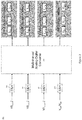
- the information available at the one or more inputs 110 of the ML-based phase current balancer 108 includes a separate time series / vector I 0 I 1 for each phase 102 of the multiphase power converter 100, 300 and a third time series / vector V err which represents the error voltage of the multiphase power converter 100, 300.
- the artificial neural network 114 includes individual first neural networks 500 for processing the separate input time series / vectors I 0 I 1 , V err and a denser second neural network 502 for combining outputs of the individual first neural networks 500.
- Artificial neural network architectures for time series handling may include recurrent neural networks.
- causal dilated neural networks may be used for time series analysis. While still being a feedforward neural network, the structure of causal dilated neural networks reduces the amount of weights which makes training and inference computationally inexpensive.
- recurrent neural networks also provide repeatable performance. Long short-term memory networks and gated recurrent units are just two examples of recurrent neural networks. Attention mechanisms may be provided to boost the performance of a recurrent neural network.
- the artificial neural network 114 of the ML-based phase current balancer 108 described herein may utilize any of these architectures, with the architecture selection depending on the exact application and associated requirements.
- the correction information PBCT x output by the artificial neural network 114 may be used to modify the modulation and/or regulation behaviour of the multiphase power converter 100, 300.
- the correction values PBCT 0 , PBCT 1 output by the ML-based phase current balancer 108 may be added/subtracted to the output REG of regulator 104 for each switching cycle. This approach may be well-suited for dual-edge regulation schemes.
- the correction values PBCT 0 , PBCT 1 output by the ML-based phase current balancer 108 may be used as an offset in the modulator 106 so that the modulation starts at an offset instead of zero in the case of PFM or PWM
- the modulator 106 uses the corrective phase current imbalance information PBCT x provided by the ML-based phase current balancer 108 in generating the modulation signals V mod,x for switching the respective phases 102.
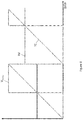
- Figure 8 provides a graphic representation of this approach.
- the regulation output together with the regulation strategy (e.g., PWM, constant on-time, PFM, etc.) and potentially an over current protection mechanism may form the basis for computing the reference value RV(t), which is updated for each phase 102 and switching cycle.
- the modulator 106 may update the reference value RV(t) for each phase 102 based on the corrective phase current imbalance information PBCTx provided by the ML-based phase current balancer 108.
- the output PBCT x of the ML-based phase current balancer 108 may become an input to the computation of the reference value RV(t), which may be updated for each switching cycle and for each phase 102 individually.
- appropriate values for the correction values PBCT 0 , PBCT 1 output by the ML-based phase current balancer 108 are learned using a reinforcement learning approach.
- Reinforcement learning is an algorithm that defines biases and weights of the artificial neural network 114. To minimize overhead, the reinforcement learning mechanism may be implemented outside the multiphase power converter controller.
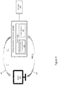
- Figure 9 illustrates an embodiment in which a host computer or another dedicated training chip 600 communicates with the multiphase power converter 100, 300.
- the multiphase power converter 100, 300 includes the ML-based phase current balancer 108, as previously explained herein.
- the host system 600 runs the reinforcement-learning algorithm.
- An interface 604 with sufficient bandwidth is provided, and/or at least a controller 602 of the multiphase power converter 100, 300 includes buffer memory 606, so that all necessary data can be accessed from the host system 600.
- the reinforcement-learning algorithm may be executed inside a computing cloud environment with a local computer PC only acting as a gateway to the host system 600.
- the controller 602 may be directly capable to directly interface with a cloud-based host system 600.
- the multiphase power converter 100, 300 is connected to a test load 608.
- the host system 600 executes a reinforcement-learning algorithm that defines biases and weights for the artificial neural network 114 included in the ML-based phase current balancer 108.
- the biases and weights learned through the reinforcement-learning algorithm enable the artificial neural network 114 to provide corrective phase current imbalance information I ph_corr,x for correcting phase current imbalance that arises within the multiphase power converter 100, 300 while connected to the test load 608.
- Connecting the multiphase power converter 100, 300 to the test load 608 provides an ML environment in which the ML agent learns an optimal phase current balancing behaviour by trial and error using feedback from the ML environment.
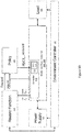
- Figure 10 illustrates an embodiment of the ML environment.
- Part of the ML agent may be located inside the multiphase power converter controller 602, e.g., inside the artificial neural network 114 of the ML-based phase current balancer 108.
- the host system 600 may provide another function of the ML agent: a policy 700 that maps the states, which are the current values of the corrective phase current imbalance information PBCTx, to some actions such as updated values for PBCTx.
- the host system 600 may also include an environment controller 702 and provide a reward function 704.
- the environment controller 702 subjects the multiphase power converter 100, 300, which is power by a power supply 706, to a plurality of tests and observing a response of the multiphase power converter 100, 300 to the tests, e.g., by recording the associated phase currents, error voltage and possible input and output voltages. From these responses, a reward function value 'Reward' is computed based on the actual responses and desired responses.
- the policy 700 maps the output values PBCTx of the artificial neural network 114 to updated output values PBCTx_updated that minimize the reward function 704.
- the reward function 704 measures how well the phase currents are being balanced during the testing process. For good phase current balance, the reward function 704 provides a high reward value. For poor phase current balance, the reward function 704 provides a low reward value. Determination of how well or how poorly the phase current balance, error voltage information V err and/or phase current information I x of the kind previously described herein may be used. Any deviation from zero values are penalized. Depending on the reward value, the policy 700 may make some changes. The changes may be made randomly, at least in the beginning. This is how weights and biases of the artificial neural network 114 are trained, to optimize (e.g. maximize or minimize) the reward function 704. The policy 700 executes reinforcement learning which carries out changes within the artificial neural network 114.
- the reward function 704, reinforcement learning algorithm and training collectively yield updated values PBCTx_updated for the artificial neural network 114.
- the types of tests that are run may be modified. For example, the tests may be different for memory, POL (point-of-load), etc.
- the ML agent approach provides much more freedom to modify the ML-based phase current balancer 108.
- the policy 700 can learn about changes in current behavior over several cycles, to prepare the multiphase power converter 100, 300.
- the reward function 704 may be programmed for the specific tests being carried out.
- the ML agent may subject the multiphase power converter 100, 300 to certain conditions and the difference of the observed values for input voltage, output voltage and phase currents is recorded and compared to optimal behavior values.
- the policy 700 attempts to find actions, e.g., updates of the PBCTx value, that allow minimizing the reward function 704.
- actions e.g., updates of the PBCTx value
- Several approaches may be implemented for the policy 700, from purely random approaches such as Monte Carlo to more sophisticated approaches such as SARSA, Q-learning, Deep Deterministic Policy Gradient, etc. In principal, all of these approaches will work but their convergence behavior may vary dramatically. Yet other policy approaches are possible.
- the ML agent may also indicate to the policy 700 and the reward function 704 overcurrent conditions that arise within the multiphase power converter 100, 300 during the tests, so that the policy 700 develops an understanding of admissible values and inadmissible areas over time and the value of the reward function 704 is set to avoid the inadmissible areas.
- the multiphase power converter 100, 300 may include an additional phase current balancer for overriding the ML-based phase current balancer 108 when the ML-based phase current balancer 108 provides an incorrect prediction which causes the phase current imbalance to worsen, e.g., when an unexpected or untested condition arises during operation that the ML-based phase current balancer 108 has not be trained for.
- the backup phase current balancer e.g.
- bang-bang may be in parallel with the ML-based phase current balancer 108.
- the output of the ML-based phase current balancer 108 may be ignored and instead the output of the backup phase current balancer is used.
- the switchover range may be set to avoid catastrophic problems such as saturated inductors, damaged switch devices, etc.
- the multiphase power converter 100, 300 may instead be shutdown system instead of providing a backup phase current balancer, when catastrophic problems arise.
- the multiphase power converter controller 602 may also have safety measures in place such procedures for handling overcurrent conditions, overtemperature conditions, etc. If a ML misprediction occurs during training, the weights/biases of the artificial neural network 114 are updated accordingly. If a ML misprediction occurs during actual field use, information about the problematic condition may be recorded for later diagnostics.
- phase over current protection may be an event provided to both the reward function 704, e.g. by giving an infinity reward value, and the policy 700.
- the policy 700 may develop over time an understanding of admissible values and inadmissible areas and avoid the inadmissible areas. For safety reasons and speed, simulations may be used for the initial part of the training process and use ML learning for fine tuning on a real system. Even the best statistical approach may fail for some corner case may arise.
- a well-balanced system may become highly unbalanced or unstable for very specific test settings, e.g. due to some resonance phenomena.
- an additional regulation scheme such as bang-bang may be run in parallel with the ML-based current balancer 108 and the two update-strategies may be mixed, e.g. by using the mean of the two output values.
- Further modifications to the approaches described herein may include providing the current and/or voltage time series information as a time series of digital values. This approach requires a very high sampling frequency of the corresponding signals. Hence, the time vector itself may be computed. Instead of modifying the reference value RV(t) of the modulator 106, a time series of a digital signal may be provided as an output of the ML-based phase current balancer 108 and that is logically combined with the signal REG provided from the regulator 104. Phase dropping and adding may also be implemented with the ML-based phase current balancing approaches described herein. Accordingly, input voltage and input current may be added to include some efficiency information and include this into the reward function 704.
- FIG 11 illustrates an embodiment of an electronic system 800 that utilizes the ML-based phase current balancer 108 described herein.
- the electronic system 800 includes a board 802 and at least one load 804 attached to the board 802.
- the load 804 is a processor subsystem which may include one or more processors and related memory.
- the term "processor” as used herein means an electronic circuit which performs operations on an external data source such as memory or some other data stream.
- processor includes CPUs, microprocessors, GPUs, DSPs, image processors, artificial intelligence (Al) accelerators, network or packet processors, coprocessors, multi-core processors, front-end processors, baseband processors, etc. The type of processor depends on the electronic system 400.
- the load 804 may be a CPU, a microprocessor, a coprocessor, a multi-core processor, a front-end processor, etc.
- the load 804 may be a baseband processor.
- the load 804 may be a GPU or an image processor.
- the load 904 may be a network or packet processor.
- a multiphase power converter 100, 300 is attached to the system board 100 and configured to provide dc power to the load 404.
- the power modules 100 may be attached to the system board 100 with each power module 100 providing one phase current to the load 404. Phases may be enabled and disabled at different points of operation, as load demand warrants.
- Each power module 100 attached to the system board 100 has the construction and function previously described herein. Accordingly, each power module 100 attached to the system board 100 provides a switch node (SW) of a half bridge circuit for supplying an output voltage to the load 404.
- SW switch node
- a multiphase power converter 100, 300 for providing dc power to the load 804 is also attached to the system board 100.
- the multiphase power converter 100, 300 includes a plurality of phases 102, each phase 102 being configured to provide a phase current I ph,x to the load 804, a modulator 106 for generating modulation signals V mod,x for switching the respective phases 102 so as to regulate an output voltage of the multiphase power converter 100, 300 provided to the load 804, and the ML-based phase current balancer 108 for aiding in balancing the phase currents I ph,x .
- the ML-based phase current balancer 108 includes one or more inputs 110, one or more outputs 112, and an artificial neural network 114 comprising a plurality of artificial neurons 400, 402, 400 and trained to provide corrective phase current imbalance information I ph_corr,x / PBCT x at the one or more outputs 112 for correcting imbalance between the individual phase currents I ph,x , based on information available at the one or more inputs 110 and indicative of the individual phase currents I ph,x .
- the information input to the ML-based phase current balancer 108 and which is indicative of the individual phase currents I ph,x may include phase current measurements I out,x for the individual phases 102, temperature information for the individual phases 102, output voltage (V out ) information for the multiphase power converter 100, error voltage (Verr) information for the multiphase power converter 100, and/or information derived from or corresponding to the individual phase modulation signals V mod,x .
Landscapes
- Engineering & Computer Science (AREA)
- Power Engineering (AREA)
- Theoretical Computer Science (AREA)
- Dc-Dc Converters (AREA)
- Physics & Mathematics (AREA)
- Computational Linguistics (AREA)
- Evolutionary Computation (AREA)
- Artificial Intelligence (AREA)
- Biomedical Technology (AREA)
- Biophysics (AREA)
- Health & Medical Sciences (AREA)
- Data Mining & Analysis (AREA)
- Life Sciences & Earth Sciences (AREA)
- General Health & Medical Sciences (AREA)
- Molecular Biology (AREA)
- Computing Systems (AREA)
- General Engineering & Computer Science (AREA)
- General Physics & Mathematics (AREA)
- Mathematical Physics (AREA)
- Software Systems (AREA)
Abstract
Description
- Multiphase power converters are commonly used when high load currents are required, e.g., for DC-DC power conversion for CPUs (central processing units), GPUs (general processing units), etc. This applies to both peak current and thermal design current. Higher load currents often require more phases.
- Multiphase power converters include at least two phases and each phase typically has a power stage and an inductor. Increasing power consumption requirements of GPUs, CPUs, and other types of electronic loads require DC-DC power converters to include additional phases in order to adequately power these systems. Implemented correctly, multiphase converters are highly advantageous in these high current applications: they combine the delivery of high currents with high energy-efficiency, low output ripple, good thermal resilience and high performance for load transient responses.
- A major challenge in harvesting the benefits of a multiphase design is phase current balance. Mainly, the energy transferred by each phase is ideally equal across the phases over one switching cycle regardless of whether the converter is exposed to a steady state or a transient load. Also, other disturbances may cause phase current imbalance, e.g., different thermal conditions for the power stages, a surge or dip in the input voltage, etc. Phase current imbalance reduces efficiency over circulating currents and may even lead to damage of the DC-DC converter and/or the connected load, e.g., by saturating the inductor. To improve efficiency for light loads, one or more phases may be deactivated under light-load conditions and reactivated if the load current increases above a given threshold. Phase dropping/adding poses another challenge when attempting to balance the phase currents.
- Phase current balance may be achieved by using the exact same components and the same layout for each phase. In addition, high quality components with very low tolerance are common. For highly critical applications, component matching may be employed. This requires components to be chosen which tolerate more current than actually needed, especially the output inductor is chosen in such a way that it does not saturate at the expected maximal phase current. This extra margin makes the solution larger, which is a problem especially for mobile devices. Also, higher voltage ratings may be considered, especially for the output capacitors. An additional regulator may be provided for balancing the phase currents. While the concepts vary slightly, the input is the individual phase current and either the regulation output or the switching voltage signal is manipulated directly. Common regulation schemes are based on an error current which is defined by the average current and the individual phase current. This commonly involves measuring the current through one or more phases by appropriate circuitry. The signals are averaged and by means of a differential amplifier, an error voltage signal is generated which is then fed to the modulator driving the phases.
- All of the measures described above resolve the phase current balancing issue to some degree. However, as power demand increases and requirements with respect to energy efficiency and transient responses tighten, more phases are being used which demands more flexible and more powerful methods for balancing the phase currents in multiphase power converters.
- Thus, there is a need for an improved phase current balancer for multiphase power converters.
- According to an embodiment of a machine learning (ML) -based phase current balancer for a multiphase power converter, the ML-based phase current balancer comprises: one or more inputs; one or more outputs; and an artificial neural network comprising a plurality of artificial neurons and trained to provide corrective phase current imbalance information at the one or more outputs for correcting phase current imbalance within the multiphase power converter, based on information available at the one or more inputs and indicative of individual phase currents of the multiphase power converter.
- According to an embodiment of a multiphase power converter, the multiphase power converter comprises: a plurality of phases, each phase being configured to provide a phase current to a load coupled to the multiphase power converter; a modulator configured to generate modulation signals for switching the respective phases so as to regulate an output voltage of the multiphase power converter provided to the load; and a machine learning (ML) -based phase current balancer configured to aid in balancing the phase currents. The ML-based phase current balancer comprises: one or more inputs; one or more outputs; and an artificial neural network comprising a plurality of artificial neurons and trained to provide corrective phase current imbalance information at the one or more outputs for correcting imbalance between the individual phase currents, based on information available at the one or more inputs and indicative of the individual phase currents.
- According to an embodiment of an electronic system, the electronic system comprises: a board; a load attached to the board; and a multiphase power converter configured to provide dc power to the load. The multiphase power converter comprises: a plurality of phases, each phase being configured to provide a phase current to the load; a modulator configured to generate modulation signals for switching the respective phases so as to regulate an output voltage of the multiphase power converter provided to the load; and a machine learning (ML) -based phase current balancer configured to aid in balancing the phase currents. The ML-based phase current balancer comprises: one or more inputs; one or more outputs; and an artificial neural network comprising a plurality of artificial neurons and trained to provide corrective phase current imbalance information at the one or more outputs for correcting imbalance between the individual phase currents, based on information available at the one or more inputs and indicative of the individual phase currents.
- According to an embodiment of a method for training a machine learning (ML) -based phase current balancer of a multiphase power converter, the method comprises: connecting the multiphase power converter to a test load; and executing a reinforcement-learning algorithm that defines biases and weights for an artificial neural network included in the ML-based phase current balancer, the biases and weights enabling the artificial neural network to provide corrective phase current imbalance information for correcting phase current imbalance that arises within the multiphase power converter while connected to the test load.
- Those skilled in the art will recognize additional features and advantages upon reading the following detailed description, and upon viewing the accompanying drawings.
- The elements of the drawings are not necessarily to scale relative to each other. Like reference numerals designate corresponding similar parts. The features of the various illustrated embodiments can be combined unless they exclude each other. Embodiments are depicted in the drawings and are detailed in the description which follows.
-
Figure 1 illustrates a block diagram of an embodiment of a multiphase power converter having a machine learning (ML) -based phase current balancer. -
Figure 2 illustrates a block diagram of an embodiment of an analog-to-digital circuit for converting transformed phase current signals into corresponding digital values. -
Figure 3 illustrates a block diagram of another embodiment of a multiphase power converter having an ML-based phase current balancer. -
Figure 4 illustrates a waveform diagram for signals of a modulator. -
Figure 5 illustrates a block diagram of an embodiment of an ML-based phase current balancer. -
Figure 6 illustrates a block diagram of an embodiment of an artificial neural network included in an ML-based phase current balancer. -
Figure 7 illustrates a block diagram of another embodiment of an artificial neural network included in an ML-based phase current balancer. -
Figure 8 illustrates a waveform diagram for modifying modulator operation based on an output of an ML-based phase current balancer. -
Figure 9 illustrates a block diagram of an embodiment of an ML-based system for training an artificial neural network of an ML-based phase current balancer. -
Figure 10 illustrates a block diagram of another embodiment of an ML-based system for training an artificial neural network of an ML-based phase current balancer. -
Figure 11 illustrates a block diagram of an embodiment of an electron system that includes a multiphase power converter having an ML-based phase current balancer. - The embodiments described herein utilize a machine learning (ML) -based method for implementing phase current balancing in multiphase power converters. The ML-based phase current balancer described herein includes an artificial neural network and is trained to provide corrective phase current imbalance information for correcting phase current imbalance within a multiphase power converter, based on information indicative of individual phase currents of the multiphase power converter. For simplification only, the ML-based phase current balancer is described herein in the context of a buck converter multiphase power converter. However, the ML-based phase current balancer may be used with any other kind of multiphase topology for power conversion such as but not limited to boost converters, buck-boost converters, etc.
- By employing a machine learning (ML) method for balancing phase current balances in a multiphase power converter, additional information such as ripple information of the output voltage also may be incorporated into the balancing procedure. Additional information about the regulation state allows the ML-based phase current balancer to develop an even more appropriate reaction to detected phase imbalances, especially during fast transients. Described next are various embodiments of the ML-based phase current balancer, methods of training the ML-based phase current balancer, and an electronic system that includes the ML-based phase current balancer.
-
Figure 1 illustrates an embodiment of amultiphase power converter 100. Themultiphase power converter 100 includesN phases 102 where N is a positive integer greater than or equal to 2. Eachphase 102 of themultiphase power converter 100 is configured to provide a phase current Iph,x to aload 104 coupled to themultiphase power converter 100. Thephases 102 may each include high-side and low-side switch devices such as power MOSFETs (metal-oxide-semiconductor field-effect transistors), related gate driver circuitry, an inductor (L), capacitors (C), etc. These components may be integrated monolithically on the same die (chip) or use a multi-die packaging technology. The driver circuitry of eachphase 102 is connected to a modulation signal Vmod,x which may be a pulsed voltage for controlling which switch of thecorresponding phase 102 is closed (conducting) and which switch device is opened (not conducting), therefore influencing the power converter output voltage Vout. - The phase modulation signals Vmod,x may be pulsed on-off (digital) signals computed from a regulation output REG and may depend on the control strategy, e.g., pulse width modulation (PWM), pulsed frequency modulation (PFM), etc. The underlying regulation scheme is implemented by a
regulator 104 such as a PID (proportional-integral-derivative) regulator. Theregulator 104 reacts based on an error voltage Verr which may be the difference between the measured output voltage value and a target voltage value Vtarget. Other implementations of the power converter regulation scheme implemented by theregulator 104 may include bang-bang regulation, PI (proportional-integral) regulation, non-linear regulation schemes, and even more advanced regulation schemes such as model predictive control (MPC), etc. - The
multiphase power converter 100 also includes amodulator 106 for generating the modulation signals Vmod,x for switching therespective phases 102 to regulate the output voltage Vout of themultiphase power converter 100 provided to theload 104. Themodulator 106 may implement PWM, PFM, or any other modulation scheme employed in multiphase power converters. - The
multiphase power converter 100 also includes a machine learning (ML) -based phasecurrent balancer 108 for balancing the phase currents Iph,x provided to theload 104. The ML-based phasecurrent balancer 108 includes one ormore inputs 110, one ormore outputs 112, and an artificial neural network (ANN) 114 having a plurality of artificial neurons. The ML-based phasecurrent balancer 108 is trained to provide corrective phase current imbalance information lPh_corr,x at the one ormore outputs 112 for correcting imbalance between the individual phase currents Iph,x, based on information available at the one ormore inputs 110 and indicative of the individual phase currents Iph,x. The ML-based phasecurrent balancer 108 may be implemented as a dedicated circuit in hardware, embedded software executed by a microprocessor or the like, or any combination thereof. - In one embodiment, the information available at the one or
more inputs 110 of the ML-based phasecurrent balancer 108 includes phase current measurements lout,x for theindividual phases 102 of themultiphase power converter 100. According to this embodiment, the artificialneural network 114 of the ML-based phasecurrent balancer 108 is trained to provide the corrective phase current imbalance information Iph_corr,x at the one ormore outputs 112 based on the phase current measurements Iout,x available at the one ormore inputs 110. - The phase current measurements Iout,x may be obtained by equipping each
phase 102 with current sensing functionality, e.g., which transforms the current Iph,x provided by thecorresponding phase 102 into a voltage. For example, the sense circuitry may implement MOSFET RDS(on) sensing where RDS(on) is the on-state of a MOSFET when in the on (conducting) state. The sense circuitry may instead sense an amplified voltage across a current sense resistor. Other current sense options are hall effect sensors, inductor direct current resistance (DCR) sensing circuits, etc. - In each case, peak phase current may be measured. The peak phase current occurs right with the falling edge of the switching signal which leads to opening of the high-side switch device and closing of the low-side switch device of the
corresponding phase 102. The peak phase current provides a good measure for the risk of system failing due to a saturated inductor. Depending on the regulation scheme, inductor values, etc., the phase current measurements Iout,x may be the average current measured from one rising edge to the next rising edge of the corresponding phase modulation signal Vmod,x. Transformed phase current signals V(Iout,x), which are voltages, may be input directly into an ADC. In another option, an analog-averaged signal of all the phase currents may be generated from the transformed phase current signals V(Iout,x). The difference between the individual phase current error and the average value may be fed as an amplified signal into an ADC. - Separately or in combination, the information available at the one or
more inputs 110 of the ML-based phasecurrent balancer 108 may include temperature information for theindividual phases 102 of themultiphase power converter 100. Temperature information available for eachphase 102 indicates whether onephase 102 is running hotter than anotherphase 102. For example, current imbalance over a long period of time, a defect in a power stage, physical location, etc. each influence temperature variation across thephases 102. The artificial neural network of the ML-based phasecurrent balancer 108 may be trained to provide corrective phase current imbalance information Iph_corr,x at the one ormore outputs 112 of the ML-based phasecurrent balancer 108 also based on phase temperature information available at the one ormore inputs 110 of the ML-based phasecurrent balancer 108. - Separately or in combination, the information available at the one or
more inputs 110 of the ML-based phasecurrent balancer 108 may include output voltage (Vout) and/or error voltage (Verr) information for themultiphase power converter 100. For example, the output voltage Vout may be fed into an ADC or an offset may be created from the output voltage Vout, e.g., with either the target voltage Vtarget or some averaged value offset. The error voltage Verr used as input for the regulation also may be input to the ML-based phasecurrent balancer 108. In each case, the artificialneural network 114 of the ML-based phasecurrent balancer 108 is trained to provide corrective phase current imbalance information lPh_corr,x at the one ormore outputs 112 based on the output voltage and/or error voltage information available at the one ormore inputs 110. -
Figure 2 illustrates an embodiment of anADC circuit 200 for converting transformed phase current signals V(Iout,x), which are voltages, into corresponding digital values. Separately or in combination, theADC circuit 200 may convert output voltage and/or error voltage information (Vout/Verr) for themultiphase power converter 100 into corresponding digital values. The transformed phase currents V(Iout,x) and/or the output / error voltage information (Vout/Verr) are fed into amulti-channel ADC 202 after having been (briefly) stored in respective sample and hold (S&H)units 204. After analog-to-digital conversion by themulti-channel ADC 202, each digitized set of values I0,x, I0,1, ..., I0,k; V0,x, V0,1, ..., V0,k is stored by a respective first-in first-out (FIFO)memory queue 206 and represents a temporal evolution of the phase current iph,x for thecorresponding phase 102 and/or output / error voltage (Vout/Verr) of themultiphase power converter 100. - The artificial
neural network 114 of the ML-based phasecurrent balancer 108 uses the digitized values I0,x, I0,1, ..., I0,k; V0,x, V0,1, ..., V0,k provided by theADC circuit 200 as input. The artificialneural network 114 is trained to provide corrective phase current imbalance information Iph_corr,x for eachphase 102 based on the digitized sets of phase current values I0,x, I0,1, ..., I0,k and/or based on the digitized set of output/error voltage values V0,x, V0,1, ..., V0,k provided by theADC circuit 200. The controller of themultiphase power converter 100 may be equipped with a multi-channel ADC, e.g., as shown inFigure 2 , or with a high-speed ADC having sample-and-hold circuits for transforming all analog voltages into digital, numerical values. - As explained above, the information input to the ML-based phase
current balancer 108 and which is indicative of the individual phase currents Iph,x may include phase current measurements Iout,x for theindividual phases 102, temperature information for theindividual phases 102, output voltage (Vout) information for themultiphase power converter 100 and/or error voltage (Verr) information for themultiphase power converter 100. Each of these approaches increases flexibility of the phase balancing approach. However, the latency - i.e. the time needed for the ML-based phasecurrent balancer 108 to react to an event - may still be high for quickly changing load conditions. For example, the current measurement for eachphase 102 must be measured, e.g., over one switching cycle, potentially averaged, then converted into a digital signal. Only then are phase current balancing computations executed by the ML-based phasecurrent balancer 108. Output voltage (Vout) and error voltage (Verr) information may have even more latency. - To further reduce latency, the information input to the ML-based phase
current balancer 108 may be derived from or correspond to the individual phase modulation signals Vmod,x instead of or in addition to direct phase current measurements Iout,x. Considering that high-performance controllers for multiphase power converters are digital, the latency described above may be reduced by inputting phase modulation information to the ML-based phasecurrent balancer 108. The phase modulation information is digital and thus has less latency than direct current measurements, and is indicative of the individual phase currents Iph,x. -
Figure 3 illustrates another embodiment of amultiphase power converter 300. Themultiphase power converter 300 shown inFigure 3 is similar to themultiphase power converter 100 shown inFigure 1 . Different, however, the information available at the one ormore inputs 110 of the ML-based phasecurrent balancer 108 includes phase modulation information such as duty cycle information tx for theindividual phases 102 of themultiphase power converter 300. The artificialneural network 114 of the ML-based phasecurrent balancer 108 is trained to provide corrective phase current imbalance information Iph_corr,x at the one ormore outputs 112 of the ML-based phasecurrent balancer 108 based on the phase modulation information available at the one ormore inputs 110 of the ML-based phasecurrent balancer 108. - For example, in the case of PWM modulation where switching frequency is fixed and the duty cycle of the modulation signals Vmod,x is adjusted to regulate the output voltage Vout of the
multiphase power converter 300, duty cycle information tx input to the ML-based phasecurrent balancer 108 may include on-time information, off-time information and tristate-time information for theindividual phases 102 of themultiphase power converter 300. The on-time information, off-time information and tristate-time information for theindividual phases 102 are digital measurements or values which relate to the phase currents iph,x. A time vector tx for eachphase 102 may be input to the ML-based phasecurrent balancer 108 and include on-time information, off-time information and tristate-time information for thatphase 102. - The
modulator 106 may provide the time vector tx to the ML-based phasecurrent balancer 108. The on-time (ton) represents the time the high-side switch device of thecorresponding phase 102 is conducting and the low-side switch device is blocking. The switching node between the high-side switch device and the low-side switch device is subjected to the input voltage (Vin) when the high-side switch device is conducting and the low-side switch device is blocking, as shown inFigure 4 . The off-time (toff) represents the time the low-side switch device of thecorresponding phase 102 is conducting and the high-side switch device is blocking. The switching node between the high-side switch device and the low-side switch device is at ground (GND) when the low-side switch device is conducting and the high-side switch device is blocking, also as shown inFigure 4 . A floating switch node voltage (Vf) is characterized by the tristate time (ttri), also as shown inFigure 4 . - The artificial
neural network 114 of the ML-based phasecurrent balancer 108 may be trained to provide corrective phase current imbalance information Iph_corr,x at the one ormore outputs 112 of the ML-based phasecurrent balancer 108 based on the phase-specific on-time information, off-time information and tristate-time information available at the one ormore inputs 110 of the ML-based phasecurrent balancer 108. The phase-specific duty cycle information tx is indicative of the individual phase currents iph,x but with less latency compared to the phase current information Iout,x since current measurement and analog-to-digital conversion steps may be skipped. Depending on requirements regarding precision, application and phase considerations, measuring the individual output currents Iout,x may be skipped since the difference between the target voltage Vtarget and the output voltage Vout also provides a good indication of whether themultiphase power converter 300 is in steady-state or subject to a load transition. -
Figure 5 illustrates an embodiment of the ML-based phasecurrent balancer 108. The artificialneural network 114 of the ML-based phasecurrent balancer 108 may be trained to provide corrective phase current imbalance information Iph_corr,x at the one ormore outputs 112 as respective correction terms PBCTX for theindividual phases 102 of themultiphase power converter phases 102. In the two-phase scenario, the ML-based phasecurrent balancer 108 produces two corrections terms PBCT0 and PBCT1 from three time series / vector inputsI 0 I 1 ,Verr . The first two time series / vector inputs,I 0 andI 1 , represent a temporal evolution of the two corresponding phase currents. The third time series / vector input,Verr , indicates the error voltage and thus the error current. Only for simplicity, it is assumed that the time series / vector inputsI 0 .I 0 , Verr to the ML-based phasecurrent balancer 108 have the same sampling frequency and the same length I. However, particularly for the error voltage time series / vector inputVerr , a higher sampling frequency may be considered for a better resolution of the ripple. An input layer of theneural network 114 may perform the transformations with respect to average currents or any other normalization as explained earlier. -
Figure 6 illustrates an embodiment of the artificialneural network 114 included in the ML-based phasecurrent balancer 108. According to this embodiment, the artificialneural network 114 is based on a multilayer perceptron or other type of feedforward neural network and includesartificial input neurons 400, artificialhidden neurons 402 andartificial output neurons 404. - The artificial
neural network 114 may be trained to set the correction terms PBCT0, PBCT1 to zero if the phase currents iph,x of themultiphase power converter multiphase power converter neural network 114 also has positive and negative branches between theartificial neurons multiphase power converter neural network 114 determines that an individual phase current iph,x is too small, the corresponding correction term PBCT0 / PBCT1 is made negative which in turn increases on-time of thecorresponding phase 102. If the artificialneural network 114 determines that an individual phase current iph,x is too large, the corresponding correction term PBCT0 / PBCT1 is made positive which in turn increases off-time of thecorresponding phase 102. - The tanh(.) activation function is shown in
Figure 6 for theartificial output neurons 404. The tanh(.) activation function yields a 1 or 0 output and therefore will provide the PBCTx values described above. Other activation functions may be used for theartificial output neurons 404 such as but not limited to ArcTan(.), SoftSign(.), ISRU(.) and SQNL(.). These activation functions also will yield the PBCTx values described above. - The intersecting lines shown in
Figure 6 indicate connections between the individualartificial neurons neural network 114 are connected densely meaning that there is a weighted connection from each and everyneuron 400/402/404 in one layer to each and everyneuron 400/402/404 in the next layer. - Regardless of the type of artificial neural network architecture, the artificial
neural network 114 may be trained to limit the correction terms PBCT0, PBCT1 regardless of the degree of phase current imbalance within themultiphase power converter multiphase power converter multiphase power converter regulator 104 which may decide, e.g., to dampen or boost accordingly. Limiting the value of the correction terms PBCT0, PBCT1 reduces the likelihood of an overcorrection under extreme conditions. - In addition to setting and possibly even limiting the permissible range of output values for the correction terms PBCT0, PBCT1, the structure of the artificial
neural network 114 may be adapted to further optimize processing efficiency. InFigures 5 and6 , the artificialneural network 114 handles four different time series / vectors:I 0 I 1 ,Verr , and PBCTx. There are many possibilities for efficiently handling the four different time series / vectorsI0 I 1 ,Verr , PBCTx using artificial neural networks. -
Figure 7 illustrates another embodiment of the artificialneural network 114 included in the ML-based phasecurrent balancer 108. According to this embodiment, the information available at the one ormore inputs 110 of the ML-based phasecurrent balancer 108 includes a separate time series / vectorI0 I 1 for eachphase 102 of themultiphase power converter Verr which represents the error voltage of themultiphase power converter neural network 114 includes individual firstneural networks 500 for processing the separate input time series / vectorsI0 I 1 ,Verr and a denser secondneural network 502 for combining outputs of the individual firstneural networks 500. - Artificial neural network architectures for time series handling may include recurrent neural networks. For example, causal dilated neural networks may be used for time series analysis. While still being a feedforward neural network, the structure of causal dilated neural networks reduces the amount of weights which makes training and inference computationally inexpensive. For time series problems, recurrent neural networks also provide repeatable performance. Long short-term memory networks and gated recurrent units are just two examples of recurrent neural networks. Attention mechanisms may be provided to boost the performance of a recurrent neural network. The artificial
neural network 114 of the ML-based phasecurrent balancer 108 described herein may utilize any of these architectures, with the architecture selection depending on the exact application and associated requirements. - The correction information PBCTx output by the artificial
neural network 114 may be used to modify the modulation and/or regulation behaviour of themultiphase power converter current balancer 108 may be added/subtracted to the output REG ofregulator 104 for each switching cycle. This approach may be well-suited for dual-edge regulation schemes. Separately or in combination, the correction values PBCT0, PBCT1 output by the ML-based phasecurrent balancer 108 may be used as an offset in themodulator 106 so that the modulation starts at an offset instead of zero in the case of PFM or PWM - In one embodiment, the
modulator 106 uses the corrective phase current imbalance information PBCTx provided by the ML-based phasecurrent balancer 108 in generating the modulation signals Vmod,x for switching the respective phases 102. For example, themodulator 106 may generate the modulation signals Vmod,x for therespective phases 102 by comparing a timer counter TC(t) to a reference value RV(t) for eachphase 102 and setting the level of the corresponding modulation signal Vmod,x accordingly, e.g., as given by:
individual phase 102. -
Figure 8 provides a graphic representation of this approach. The regulation output together with the regulation strategy (e.g., PWM, constant on-time, PFM, etc.) and potentially an over current protection mechanism may form the basis for computing the reference value RV(t), which is updated for eachphase 102 and switching cycle. Themodulator 106 may update the reference value RV(t) for eachphase 102 based on the corrective phase current imbalance information PBCTx provided by the ML-based phasecurrent balancer 108. - The output PBCTx of the ML-based phase
current balancer 108 may become an input to the computation of the reference value RV(t), which may be updated for each switching cycle and for eachphase 102 individually. For example, themodulator 106 may add the output PBCTx of the ML-based phasecurrent balancer 108 as a correction term PBCT(t) to the reference value RV(t) for thecorresponding phase 102 as given by:
- Described next are various embodiments for training the ML-based phase
current balancer 108. In one embodiment, appropriate values for the correction values PBCT0, PBCT1 output by the ML-based phasecurrent balancer 108 are learned using a reinforcement learning approach. Reinforcement learning is an algorithm that defines biases and weights of the artificialneural network 114. To minimize overhead, the reinforcement learning mechanism may be implemented outside the multiphase power converter controller. -
Figure 9 illustrates an embodiment in which a host computer or anotherdedicated training chip 600 communicates with themultiphase power converter multiphase power converter current balancer 108, as previously explained herein. Thehost system 600 runs the reinforcement-learning algorithm. Aninterface 604 with sufficient bandwidth is provided, and/or at least acontroller 602 of themultiphase power converter buffer memory 606, so that all necessary data can be accessed from thehost system 600. Besides a direct connection to thehost system 600, the reinforcement-learning algorithm may be executed inside a computing cloud environment with a local computer PC only acting as a gateway to thehost system 600. For some applications, thecontroller 602 may be directly capable to directly interface with a cloud-basedhost system 600. - To train the ML-based phase
current balancer 108, themultiphase power converter test load 608. Thehost system 600 executes a reinforcement-learning algorithm that defines biases and weights for the artificialneural network 114 included in the ML-based phasecurrent balancer 108. The biases and weights learned through the reinforcement-learning algorithm enable the artificialneural network 114 to provide corrective phase current imbalance information Iph_corr,x for correcting phase current imbalance that arises within themultiphase power converter test load 608. Connecting themultiphase power converter test load 608 provides an ML environment in which the ML agent learns an optimal phase current balancing behaviour by trial and error using feedback from the ML environment. -
Figure 10 illustrates an embodiment of the ML environment. Part of the ML agent may be located inside the multiphasepower converter controller 602, e.g., inside the artificialneural network 114 of the ML-based phasecurrent balancer 108. Thehost system 600 may provide another function of the ML agent: apolicy 700 that maps the states, which are the current values of the corrective phase current imbalance information PBCTx, to some actions such as updated values for PBCTx. Thehost system 600 may also include anenvironment controller 702 and provide areward function 704. In one embodiment, theenvironment controller 702 subjects themultiphase power converter power supply 706, to a plurality of tests and observing a response of themultiphase power converter policy 700 maps the output values PBCTx of the artificialneural network 114 to updated output values PBCTx_updated that minimize thereward function 704. - The
reward function 704 measures how well the phase currents are being balanced during the testing process. For good phase current balance, thereward function 704 provides a high reward value. For poor phase current balance, thereward function 704 provides a low reward value. Determination of how well or how poorly the phase current balance, error voltage informationVerr and/or phase current informationIx of the kind previously described herein may be used. Any deviation from zero values are penalized. Depending on the reward value, thepolicy 700 may make some changes. The changes may be made randomly, at least in the beginning. This is how weights and biases of the artificialneural network 114 are trained, to optimize (e.g. maximize or minimize) thereward function 704. Thepolicy 700 executes reinforcement learning which carries out changes within the artificialneural network 114. - The
reward function 704, reinforcement learning algorithm and training collectively yield updated values PBCTx_updated for the artificialneural network 114. Depending on the application, the types of tests that are run may be modified. For example, the tests may be different for memory, POL (point-of-load), etc. The ML agent approach provides much more freedom to modify the ML-based phasecurrent balancer 108. Thepolicy 700 can learn about changes in current behavior over several cycles, to prepare themultiphase power converter reward function 704 may be programmed for the specific tests being carried out. - To compute the value of the
reward function 704, the ML agent may subject themultiphase power converter - The
policy 700 attempts to find actions, e.g., updates of the PBCTx value, that allow minimizing thereward function 704. Several approaches may be implemented for thepolicy 700, from purely random approaches such as Monte Carlo to more sophisticated approaches such as SARSA, Q-learning, Deep Deterministic Policy Gradient, etc. In principal, all of these approaches will work but their convergence behavior may vary dramatically. Yet other policy approaches are possible. - The ML agent may also indicate to the
policy 700 and thereward function 704 overcurrent conditions that arise within themultiphase power converter policy 700 develops an understanding of admissible values and inadmissible areas over time and the value of thereward function 704 is set to avoid the inadmissible areas. - Other safeguards may be taken. For example, the ML approach is statistics-driven and therefore incorrect predictions may occur. Accordingly, limits may be placed on what the ML-based phase
current balancer 108 is permitted to do and not do. If evolution of the phase current balancing goes far off, the ML approach may be modified. Separately or in addition, themultiphase power converter current balancer 108 when the ML-based phasecurrent balancer 108 provides an incorrect prediction which causes the phase current imbalance to worsen, e.g., when an unexpected or untested condition arises during operation that the ML-based phasecurrent balancer 108 has not be trained for. The backup phase current balancer, e.g. bang-bang, may be in parallel with the ML-based phasecurrent balancer 108. When the phase current balancing results fall outside a defined range, the output of the ML-based phasecurrent balancer 108 may be ignored and instead the output of the backup phase current balancer is used. The switchover range may be set to avoid catastrophic problems such as saturated inductors, damaged switch devices, etc. Themultiphase power converter power converter controller 602 may also have safety measures in place such procedures for handling overcurrent conditions, overtemperature conditions, etc. If a ML misprediction occurs during training, the weights/biases of the artificialneural network 114 are updated accordingly. If a ML misprediction occurs during actual field use, information about the problematic condition may be recorded for later diagnostics. - The ML learning process described herein may result in settings which cause the
multiphase power converter reward function 704, e.g. by giving an infinity reward value, and thepolicy 700. Thepolicy 700 may develop over time an understanding of admissible values and inadmissible areas and avoid the inadmissible areas. For safety reasons and speed, simulations may be used for the initial part of the training process and use ML learning for fine tuning on a real system. Even the best statistical approach may fail for some corner case may arise. For example, a well-balanced system may become highly unbalanced or unstable for very specific test settings, e.g. due to some resonance phenomena. As explained above, an additional regulation scheme such as bang-bang may be run in parallel with the ML-basedcurrent balancer 108 and the two update-strategies may be mixed, e.g. by using the mean of the two output values. - Further modifications to the approaches described herein may include providing the current and/or voltage time series information as a time series of digital values. This approach requires a very high sampling frequency of the corresponding signals. Hence, the time vector itself may be computed. Instead of modifying the reference value RV(t) of the
modulator 106, a time series of a digital signal may be provided as an output of the ML-based phasecurrent balancer 108 and that is logically combined with the signal REG provided from theregulator 104. Phase dropping and adding may also be implemented with the ML-based phase current balancing approaches described herein. Accordingly, input voltage and input current may be added to include some efficiency information and include this into thereward function 704. -
Figure 11 illustrates an embodiment of anelectronic system 800 that utilizes the ML-based phasecurrent balancer 108 described herein. Theelectronic system 800 includes aboard 802 and at least oneload 804 attached to theboard 802. In one embodiment, theload 804 is a processor subsystem which may include one or more processors and related memory. The term "processor" as used herein means an electronic circuit which performs operations on an external data source such as memory or some other data stream. The term "processor" as used herein includes CPUs, microprocessors, GPUs, DSPs, image processors, artificial intelligence (Al) accelerators, network or packet processors, coprocessors, multi-core processors, front-end processors, baseband processors, etc. The type of processor depends on theelectronic system 400. For example, in the case of a computer, server, mobile device, etc., theload 804 may be a CPU, a microprocessor, a coprocessor, a multi-core processor, a front-end processor, etc. In the case of a network interface that manages radio functions of a wireless network, theload 804 may be a baseband processor. In the case of a graphics card, theload 804 may be a GPU or an image processor. In the case of a network interface card, the load 904 may be a network or packet processor. These are just some examples of electronic systems and related loads, and should not be considered limiting. - A
multiphase power converter system board 100 and configured to provide dc power to theload 404. For example, in the case of a multi-phase VR, at least two of thepower modules 100 may be attached to thesystem board 100 with eachpower module 100 providing one phase current to theload 404. Phases may be enabled and disabled at different points of operation, as load demand warrants. Eachpower module 100 attached to thesystem board 100 has the construction and function previously described herein. Accordingly, eachpower module 100 attached to thesystem board 100 provides a switch node (SW) of a half bridge circuit for supplying an output voltage to theload 404. - A
multiphase power converter load 804 is also attached to thesystem board 100. The multiphase power converter 100, 300 includes a plurality of phases 102, each phase 102 being configured to provide a phase current Iph,x to the load 804, a modulator 106 for generating modulation signals Vmod,x for switching the respective phases 102 so as to regulate an output voltage of the multiphase power converter 100, 300 provided to the load 804, and the ML-based phase current balancer 108 for aiding in balancing the phase currents Iph,x. As previously explained herein, the ML-based phase current balancer 108 includes one or more inputs 110, one or more outputs 112, and an artificial neural network 114 comprising a plurality of artificial neurons 400, 402, 400 and trained to provide corrective phase current imbalance information Iph_corr,x / PBCTx at the one or more outputs 112 for correcting imbalance between the individual phase currents Iph,x, based on information available at the one or more inputs 110 and indicative of the individual phase currents Iph,x. As previously explained herein, the information input to the ML-based phase current balancer 108 and which is indicative of the individual phase currents Iph,x may include phase current measurements Iout,x for the individual phases 102, temperature information for the individual phases 102, output voltage (Vout) information for the multiphase power converter 100, error voltage (Verr) information for the multiphase power converter 100, and/or information derived from or corresponding to the individual phase modulation signals Vmod,x. - Although the present disclosure is not so limited, the following numbered examples demonstrate one or more aspects of the disclosure.
- Example 1. A machine learning (ML) -based phase current balancer for a multiphase power converter, the ML-based phase current balancer comprising: one or more inputs; one or more outputs; and an artificial neural network comprising a plurality of artificial neurons and trained to provide corrective phase current imbalance information at the one or more outputs for correcting phase current imbalance within the multiphase power converter, based on information available at the one or more inputs and indicative of individual phase currents of the multiphase power converter.
- Example 2. The ML-based phase current balancer of example 1, wherein the information available at the one or more inputs comprises phase current measurements for individual phases of the multiphase power converter, and wherein the artificial neural network is trained to provide the corrective phase current imbalance information at the one or more outputs based on the phase current measurements available at the one or more inputs.
- Example 3. The ML-based phase current balancer of example 2, wherein the phase current measurements available at the one or more inputs represent a temporal evolution of the phase current for the individual phases of the multiphase power converter.
- Example 4. The ML-based phase current balancer of examples 2 or 3, wherein the information available at the one or more inputs further comprises output voltage and/or error voltage information for the multiphase power converter, and wherein the artificial neural network is trained to provide the corrective phase current imbalance information at the one or more outputs also based on the output voltage and/or error voltage information available at the one or more inputs.
- Example 5. The ML-based phase current balancer of example 4, further comprising analog-to-digital converter circuitry and a memory queue, wherein the phase current measurements and the output voltage and/or error voltage information are available at the one or more inputs as respective individual voltages, and wherein the analog-to-digital converter circuitry is configured to convert the individual voltages into respective individual digital values for storage in the memory queue for input to the artificial neural network.
- Example 6. The ML-based phase current balancer of any of examples 2 through 5, wherein the information available at the one or more inputs further comprises temperature information for the individual phases of the multiphase power converter, and wherein the artificial neural network is trained to provide the corrective phase current imbalance information at the one or more outputs also based on the temperature information available at the one or more inputs.
- Example 7. The ML-based phase current balancer of any of examples 1 through 6, wherein the information available at the one or more inputs comprises duty cycle information for individual phases of the multiphase power converter, and wherein the artificial neural network is trained to provide the corrective phase current imbalance information at the one or more outputs based on the duty cycle information available at the one or more inputs.
- Example 8. The ML-based phase current balancer of any of examples 1 through 7, wherein the information available at the one or more inputs comprises on-time information, off-time information and tristate-time information for the individual phases of the multiphase power converter, and wherein the artificial neural network is trained to provide the corrective phase current imbalance information at the one or more outputs based on the on-time information, the off-time information and the tristate-time information available at the one or more inputs.
- Example 9. The ML-based phase current balancer of example 8, wherein the information available at the one or more inputs further comprises output voltage and/or error voltage information for the multiphase power converter, and wherein the artificial neural network is trained to provide the corrective phase current imbalance information at the one or more outputs also based on the output voltage and/or error voltage information available at the one or more inputs.
- Example 10. The ML-based phase current balancer of example 8 or 9, wherein the information available at the one or more inputs further comprises temperature information for the individual phases of the multiphase power converter, and wherein the artificial neural network is trained to provide the corrective phase current imbalance information at the one or more outputs also based on the temperature information available at the one or more inputs.
- Example 11. The ML-based phase current balancer of any of examples 1 through 10, wherein the information available at the one or more inputs comprises error voltage information indicative of a difference between a target voltage and an output voltage of the multiphase power converter, and wherein the artificial neural network is trained to provide the corrective phase current imbalance information at the one or more outputs based on the error voltage information available at the one or more inputs.
- Example 12. The ML-based phase current balancer of any of examples 1 through 11, wherein the artificial neural network is trained to provide the corrective phase current imbalance information at the one or more outputs as respective correction terms for individual phases of the multiphase power converter.
- Example 13. The ML-based phase current balancer of example 12, wherein the artificial neural network is trained to set the correction terms to zero if the phase currents of the multiphase power converter are balanced and a voltage error for the multiphase power converter is within a defined range, and wherein the artificial neural network comprises positive and negative branches between the artificial neurons such that an individual one of the correction terms is negative if the corresponding phase current of the multiphase power converter is below a first threshold and positive if the corresponding phase current is above a second threshold.
- Example 14. The ML-based phase current balancer of examples 12 or 13, wherein the artificial neural network is trained to limit the correction terms regardless of the degree of phase current imbalance within the multiphase power converter and/or an amount of voltage error for the multiphase power converter.
- Example 15. The ML-based phase current balancer of any of examples 1 through 14, wherein the information available at the one or more inputs comprises a separate time series or time vector for each phase of the multiphase power converter, and wherein the artificial neural network comprises individual first neural networks for processing the separate time series or time vector and a denser second neural network for combining outputs of the individual first neural networks.
- Example 16. A multiphase power converter, comprising: a plurality of phases, each phase being configured to provide a phase current to a load coupled to the multiphase power converter; a modulator configured to generate modulation signals for switching the respective phases so as to regulate an output voltage of the multiphase power converter provided to the load; and a machine learning (ML) -based phase current balancer configured to aid in balancing the phase currents. The ML-based phase current balancer comprises: one or more inputs; one or more outputs; and an artificial neural network comprising a plurality of artificial neurons and trained to provide corrective phase current imbalance information at the one or more outputs for correcting imbalance between the individual phase currents, based on information available at the one or more inputs and indicative of the individual phase currents.
- Example 17. The multiphase power converter of example 16, wherein the modulator is configured to use the corrective phase current imbalance information provided by the ML-based phase current balancer in generating the modulation signals for switching the respective phases.
- Example 18. The multiphase power converter of example 17, wherein the modulator is configured to generate the modulation signals for the respective phases by comparing a timer counter to a reference value for each phase, and wherein the modulator is configured to update the reference value for each phase based on the corrective phase current imbalance information provided by the ML-based phase current balancer.
- Example 19. The multiphase power converter of example 18, wherein the artificial neural network of the ML-based phase current balancer is trained to provide the corrective phase current imbalance information at the one or more outputs as respective correction terms for the individual phases, and wherein the modulator is configured to update the reference value for each individual phase by adding the respective correction term to the corresponding reference value for each individual phase.
- Example 20. The multiphase power converter of any of examples 16 through 19, wherein the information available at the one or more inputs of the ML-based phase current balancer comprises on-time information, off-time information and tristate-time information for the individual phases of the multiphase power converter, wherein the artificial neural network of the ML-based phase current balancer is trained to provide the corrective phase current imbalance information at the one or more outputs based on the on-time information, the off-time information and the tristate-time information available at the one or more inputs, and wherein the modulator is configured to provide the on-time information, the off-time information and the tristate-time information to the one or more inputs of the ML-based phase current balancer.
- Example 21. The multiphase power converter of any of examples 16 through 20, further comprising an additional phase current balancer that overrides the ML-based phase current balancer when the ML-based phase current balancer provides an incorrect prediction which causes the phase current imbalance to worsen.
- Example 22. An electronic system, comprising: a board; a load attached to the board; and a multiphase power converter configured to provide dc power to the load. The multiphase power converter comprises: a plurality of phases, each phase being configured to provide a phase current to the load; a modulator configured to generate modulation signals for switching the respective phases so as to regulate an output voltage of the multiphase power converter provided to the load; and a machine learning (ML) -based phase current balancer configured to aid in balancing the phase currents. The ML-based phase current balancer comprises: one or more inputs; one or more outputs; and an artificial neural network comprising a plurality of artificial neurons and trained to provide corrective phase current imbalance information at the one or more outputs for correcting imbalance between the individual phase currents, based on information available at the one or more inputs and indicative of the individual phase currents.
- Example 23. A method for training a machine learning (ML) -based phase current balancer of a multiphase power converter, the method comprising: connecting the multiphase power converter to a test load; and executing a reinforcement-learning algorithm that defines biases and weights for an artificial neural network included in the ML-based phase current balancer, the biases and weights enabling the artificial neural network to provide corrective phase current imbalance information for correcting phase current imbalance that arises within the multiphase power converter while connected to the test load.
- Example 24. The method of example 23, wherein executing the reinforcement-learning algorithm comprises: subjecting the multiphase power converter to a plurality of tests and observing a response of the multiphase power converter to the tests; computing a value of a reward function based on a difference between the response of the multiphase power converter to a test and a target response; and implementing a policy that maps output values of the artificial neural network to updated output values that minimize the reward function.
- Example 25. The method of example 24, further comprising: indicating to the policy and the reward function overcurrent conditions that arise within the multiphase power converter during the tests, so that the policy develops an understanding of admissible values and inadmissible areas over time and the value of the reward function is set to avoid the inadmissible areas.
- Terms such as "first", "second", and the like, are used to describe various elements, regions, sections, etc. and are also not intended to be limiting. Like terms refer to like elements throughout the description.
- As used herein, the terms "having", "containing", "including", "comprising" and the like are open ended terms that indicate the presence of stated elements or features, but do not preclude additional elements or features. The articles "a", "an" and "the" are intended to include the plural as well as the singular, unless the context clearly indicates otherwise.
- It is to be understood that the features of the various embodiments described herein may be combined with each other, unless specifically noted otherwise.
Claims (16)
- A machine learning (ML) -based phase current balancer for a multiphase power converter, the ML-based phase current balancer (108) comprising:one or more inputs (110);one or more outputs (112); andan artificial neural network (114) comprising a plurality of artificial neurons and trained to provide corrective phase current imbalance information at the one or more outputs (112) for correcting phase current imbalance within the multiphase power converter, based on information available at the one or more inputs and indicative of individual phase currents (Iph,0, Iph,1, Iph,n-1) of the multiphase power converter.
- The ML-based phase current balancer of claim 1,
wherein the information available at the one or more inputs (110) comprises phase current measurements for individual phases of the multiphase power converter, and
wherein the artificial neural network (114) is trained to provide the corrective phase current imbalance information at the one or more outputs (112) based on the phase current measurements available at the one or more inputs (110). - The ML-based phase current balancer of claim 2, wherein the phase current measurements available at the one or more inputs (110) represent a temporal evolution of the phase current (Iph,0, Iph,1, Iph,n-1) for the individual phases of the multiphase power converter.
- The ML-based phase current balancer of claim 2 or 3,
wherein the information available at the one or more inputs (110) further comprises output voltage and/or error voltage information for the multiphase power converter, and
wherein the artificial neural network is trained to provide the corrective phase current imbalance information at the one or more outputs (112) also based on the output voltage and/or error voltage information available at the one or more inputs (110) . - The ML-based phase current balancer of claim 4, further comprising analog-to-digital converter circuitry (202) and a memory queue (206),
wherein the phase current measurements and the output voltage and/or error voltage information are available at the one or more inputs as respective individual voltages, and
wherein the analog-to-digital converter circuitry (202) is configured to convert the individual voltages into respective individual digital values for storage in the memory queue (206) for input to the artificial neural network (114). - The ML-based phase current balancer of any one of claims 2 to 5,
wherein the information available at the one or more inputs (110) further comprises temperature information for the individual phases of the multiphase power converter, and
wherein the artificial neural network /114) is trained to provide the corrective phase current imbalance information at the one or more outputs (112) also based on the temperature information available at the one or more inputs (110). - The ML-based phase current balancer of claim 1,
wherein the information available at the one or more inputs comprises duty cycle information for individual phases of the multiphase power converter, and
wherein the artificial neural network (114) is trained to provide the corrective phase current imbalance information at the one or more outputs (112) based on the duty cycle information available at the one or more inputs (110). - The ML-based phase current balancer of claim 1,
wherein the information available at the one or more inputs (110) comprises on-time information, off-time information and tristate-time information for the individual phases of the multiphase power converter, and
wherein the artificial neural network (114) is trained to provide the corrective phase current imbalance information at the one or more outputs based on the on-time information, the off-time information and the tristate-time information available at the one or more inputs (110). - The ML-based phase current balancer of claim 8,
wherein the information available at the one or more inputs (110) further comprises output voltage and/or error voltage information for the multiphase power converter, and
wherein the artificial neural network (114) is trained to provide the corrective phase current imbalance information at the one or more outputs (112) also based on the output voltage and/or error voltage information available at the one or more inputs (110) . - The ML-based phase current balancer of claim 8,
wherein the information available at the one or more inputs (110) further comprises temperature information for the individual phases of the multiphase power converter, and
wherein the artificial neural network (114) is trained to provide the corrective phase current imbalance information at the one or more outputs (112) also based on the temperature information available at the one or more inputs (110). - The ML-based phase current balancer of claim 1,
wherein the information available at the one or more inputs (110) comprises error voltage information indicative of a difference between a target voltage and an output voltage of the multiphase power converter, and
wherein the artificial neural network (114) is trained to provide the corrective phase current imbalance information at the one or more outputs (112) based on the error voltage information available at the one or more inputs (110). - The ML-based phase current balancer of any one of the preceding claims, wherein the artificial neural network (114) is trained to provide the corrective phase current imbalance information at the one or more outputs (112) as respective correction terms for individual phases of the multiphase power converter.
- The ML-based phase current balancer of claim 1, wherein the information available at the one or more inputs comprises a separate time series or time vector for each phase of the multiphase power converter, and wherein the artificial neural network comprises individual first neural networks for processing the separate time series or time vector and a denser second neural network for combining outputs of the individual first neural networks.
- A multiphase power converter, comprising:a plurality of phases (102), each phase (102) being configured to provide a phase current (Iph,0, Iph,1, Iph,n-1) to a load (104) coupled to the multiphase power converter;a modulator (106) configured to generate modulation signals for switching the respective phases (102) so as to regulate an output voltage (Vout) of the multiphase power converter provided to the load (104); anda machine learning (ML) -based phase current balancer (108) according to any one of claims 1 to 13.
- An electronic system, comprising:a board;a load (104) attached to the board; anda multiphase power converter according to claim 14 configured to provide dc power to the load (104).
- A method for training a machine learning (ML) -based phase current balancer of a multiphase power converter, the method comprising:connecting the multiphase power converter to a test load; andexecuting a reinforcement-learning algorithm that defines biases and weights for an artificial neural network included in the ML-based phase current balancer, the biases and weights enabling the artificial neural network to provide corrective phase current imbalance information for correcting phase current imbalance that arises within the multiphase power converter while connected to the test load.
Applications Claiming Priority (1)
| Application Number | Priority Date | Filing Date | Title |
|---|---|---|---|
| US16/841,213 US11646748B2 (en) | 2020-04-06 | 2020-04-06 | ML-based phase current balancer |
Publications (1)
| Publication Number | Publication Date |
|---|---|
| EP3893375A1 true EP3893375A1 (en) | 2021-10-13 |
Family
ID=75362517
Family Applications (1)
| Application Number | Title | Priority Date | Filing Date |
|---|---|---|---|
| EP21166738.1A Withdrawn EP3893375A1 (en) | 2020-04-06 | 2021-04-01 | Phase current balancer using artificial neural network |
Country Status (3)
| Country | Link |
|---|---|
| US (1) | US11646748B2 (en) |
| EP (1) | EP3893375A1 (en) |
| CN (1) | CN113497553A (en) |
Families Citing this family (3)
| Publication number | Priority date | Publication date | Assignee | Title |
|---|---|---|---|---|
| US11228248B1 (en) * | 2020-08-13 | 2022-01-18 | Semiconductor Components Industries, Llc | Multiphase controller with failure diagnostic mechanism |
| CN114118404A (en) * | 2021-10-20 | 2022-03-01 | 广西电网有限责任公司 | Electric energy meter phase unbalance state syndrome research and judgment method based on neural network |
| GB202307717D0 (en) * | 2023-05-23 | 2023-07-05 | Tdk Lambda Uk Ltd | Controller for a multi-phase power converter, multi-phase power converter, multi-phase power converter and method |
Family Cites Families (15)
| Publication number | Priority date | Publication date | Assignee | Title |
|---|---|---|---|---|
| US5003243A (en) * | 1987-09-29 | 1991-03-26 | Kabushiki Kaisha Toshiba | Control apparatus for induction machine |
| US5196778A (en) * | 1989-06-23 | 1993-03-23 | Mitsubishi Denki Kabushiki Kaisha | Control apparatus suitable for use in induction motor |
| GB2261966B (en) * | 1991-11-30 | 1995-11-08 | Toshiba Kk | Driving control apparatus for induction motor |
| US5576632A (en) * | 1994-06-30 | 1996-11-19 | Siemens Corporate Research, Inc. | Neural network auto-associator and method for induction motor monitoring |
| US5943660A (en) * | 1995-06-28 | 1999-08-24 | Board Of Regents The University Of Texas System | Method for feedback linearization of neural networks and neural network incorporating same |
| US6215271B1 (en) * | 1999-05-11 | 2001-04-10 | Satcon Technology Corporation | Charging system having a controlled rectifier bridge and a single voltage sensor |
| US6629089B1 (en) * | 2000-09-29 | 2003-09-30 | Cirrus Logic, Inc. | Artificial neural network voice coil motor controller |
| US6630809B2 (en) * | 2001-11-29 | 2003-10-07 | Ballard Power Systems Corporation | System and method for induction motor control |
| US7187155B2 (en) * | 2004-05-14 | 2007-03-06 | Rockwell Automation Technologies, Inc. | Leakage inductance saturation compensation for a slip control technique of a motor drive |
| US7602164B2 (en) * | 2006-04-10 | 2009-10-13 | Hai Huu Vo | Adaptive DC to DC converter system |
| US7903433B2 (en) * | 2007-12-26 | 2011-03-08 | Texas Instruments Incorporated | Current balancing for multi-phase converters |
| US7888923B2 (en) | 2009-03-27 | 2011-02-15 | Texas Instruments Incorporated | Dynamic phase manager for multi-phase switching regulators |
| US9369043B2 (en) | 2012-10-23 | 2016-06-14 | Texas Instruments Deutschland Gmbh | Phase current balancing for multiphase converters |
| US10333390B2 (en) * | 2015-05-08 | 2019-06-25 | The Board Of Trustees Of The University Of Alabama | Systems and methods for providing vector control of a grid connected converter with a resonant circuit grid filter |
| US10797589B2 (en) * | 2017-09-28 | 2020-10-06 | Texas Instruments Incorporated | Methods and apparatus to compensate for power factor loss using a phasor cancellation based compensation scheme |
-
2020
- 2020-04-06 US US16/841,213 patent/US11646748B2/en active Active
-
2021
- 2021-04-01 EP EP21166738.1A patent/EP3893375A1/en not_active Withdrawn
- 2021-04-02 CN CN202110361610.4A patent/CN113497553A/en active Pending
Non-Patent Citations (4)
| Title |
|---|
| HU KAI-YU ET AL: "A Digital Multiphase Converter with Sensor-less Current and Thermal Balance Mechanism", 2018 IEEE ASIAN SOLID-STATE CIRCUITS CONFERENCE (A-SSCC), IEEE, 5 November 2018 (2018-11-05), pages 175 - 178, XP033474552, DOI: 10.1109/ASSCC.2018.8579301 * |
| JASOUR A M Z ET AL: "Design of a MIMO controller for a multimodul Dc-Dc converter based on Particle Swarm Optimized neural network", POWER AND ENERGY CONFERENCE, 2008. PECON 2008. IEEE 2ND INTERNATIONAL, IEEE, PISCATAWAY, NJ, USA, 1 December 2008 (2008-12-01), pages 224 - 230, XP031412910, ISBN: 978-1-4244-2404-7 * |
| LUKIC Z ET AL: "Sensorless Self-Tuning Digital CPM Controller With Multiple Parameter Estimation and Thermal Stress Equalization", IEEE TRANSACTIONS ON POWER ELECTRONICS, INSTITUTE OF ELECTRICAL AND ELECTRONICS ENGINEERS, USA, vol. 26, no. 12, 1 December 2011 (2011-12-01), pages 3948 - 3963, XP011479935, ISSN: 0885-8993, DOI: 10.1109/TPEL.2011.2131684 * |
| MARUTA HIDENORI ET AL: "Improvement of current balanced parallel soft-start operation for dc-dc converters with current prediction", 2015 INTERNATIONAL CONFERENCE ON RENEWABLE ENERGY RESEARCH AND APPLICATIONS (ICRERA), IEEE, 22 November 2015 (2015-11-22), pages 1058 - 1062, XP032873843, DOI: 10.1109/ICRERA.2015.7418572 * |
Also Published As
| Publication number | Publication date |
|---|---|
| CN113497553A (en) | 2021-10-12 |
| US20210312275A1 (en) | 2021-10-07 |
| US11646748B2 (en) | 2023-05-09 |
Similar Documents
| Publication | Publication Date | Title |
|---|---|---|
| Peng et al. | Application of digital twin concept in condition monitoring for dc-dc converter | |
| US9645626B2 (en) | Circuits and methods providing supply voltage control based on transient load prediction | |
| US11646748B2 (en) | ML-based phase current balancer | |
| US7791324B2 (en) | Switching regulator without a dedicated input current sense element | |
| US9958356B2 (en) | Process and device for testing the powertrain of at least partially electrically driven vehicles | |
| CN107707118B (en) | Electronic device including power management integrated circuit | |
| US20070222463A1 (en) | Power conversion efficiency management | |
| Poblete et al. | Distributed neural network observer for submodule capacitor voltage estimation in modular multilevel converters | |
| US9086707B2 (en) | System and method for modulating a duty cycle of a switching mode power supply | |
| US10622897B2 (en) | Controller for buck DC/DC converter with effective decoupling | |
| US10148256B2 (en) | Signal generating circuit, voltage conversion device, and signal generating method | |
| EP3972100A1 (en) | Ai-based error prediction for power conversion regulators | |
| EP3902130A1 (en) | Current emulation in a power supply | |
| CN101446997A (en) | Power electronic circuit optimization method based on particle swarm algorithm | |
| US11327553B2 (en) | Distributed digital low-dropout voltage micro regulator | |
| CN113157045A (en) | Voltage regulator circuit and method | |
| CN107615662A (en) | Signal generating circuit, voltage conversion device and computer program | |
| Shenoy et al. | Power supply aware computing | |
| EP4645663A1 (en) | Parallel power supply device and program | |
| EP3148063A1 (en) | Predictive current share system and control method for controlling this system | |
| Halivni et al. | Transient suppression scheme for mitigation of high-performance VRM intricate load profiles | |
| Etz et al. | A comparison between digital and analog control for a buck converter | |
| KR20180023477A (en) | Uninterruptible power supply for unbalanced load | |
| JP6556407B1 (en) | Switching power supply apparatus and power supply apparatus for nuclear magnetic resonance imaging apparatus using the same | |
| Xu | Optimization of system identification for multi-rail DC-DC power converters |
Legal Events
| Date | Code | Title | Description |
|---|---|---|---|
| PUAI | Public reference made under article 153(3) epc to a published international application that has entered the european phase |
Free format text: ORIGINAL CODE: 0009012 |
|
| STAA | Information on the status of an ep patent application or granted ep patent |
Free format text: STATUS: THE APPLICATION HAS BEEN PUBLISHED |
|
| AK | Designated contracting states |
Kind code of ref document: A1 Designated state(s): AL AT BE BG CH CY CZ DE DK EE ES FI FR GB GR HR HU IE IS IT LI LT LU LV MC MK MT NL NO PL PT RO RS SE SI SK SM TR |
|
| STAA | Information on the status of an ep patent application or granted ep patent |
Free format text: STATUS: REQUEST FOR EXAMINATION WAS MADE |
|
| 17P | Request for examination filed |
Effective date: 20220413 |
|
| RBV | Designated contracting states (corrected) |
Designated state(s): AL AT BE BG CH CY CZ DE DK EE ES FI FR GB GR HR HU IE IS IT LI LT LU LV MC MK MT NL NO PL PT RO RS SE SI SK SM TR |
|
| STAA | Information on the status of an ep patent application or granted ep patent |
Free format text: STATUS: EXAMINATION IS IN PROGRESS |
|
| 17Q | First examination report despatched |
Effective date: 20230629 |
|
| STAA | Information on the status of an ep patent application or granted ep patent |
Free format text: STATUS: THE APPLICATION IS DEEMED TO BE WITHDRAWN |
|
| 18D | Application deemed to be withdrawn |
Effective date: 20240110 |