EP3893333A1 - Connector module - Google Patents
Connector module Download PDFInfo
- Publication number
- EP3893333A1 EP3893333A1 EP21165791.1A EP21165791A EP3893333A1 EP 3893333 A1 EP3893333 A1 EP 3893333A1 EP 21165791 A EP21165791 A EP 21165791A EP 3893333 A1 EP3893333 A1 EP 3893333A1
- Authority
- EP
- European Patent Office
- Prior art keywords
- connector
- case
- housing
- tubular shell
- module
- Prior art date
- Legal status (The legal status is an assumption and is not a legal conclusion. Google has not performed a legal analysis and makes no representation as to the accuracy of the status listed.)
- Withdrawn
Links
- 230000005489 elastic deformation Effects 0.000 claims abstract description 7
- 239000012212 insulator Substances 0.000 claims description 15
- 239000004020 conductor Substances 0.000 description 55
- 230000007246 mechanism Effects 0.000 description 10
- 238000006073 displacement reaction Methods 0.000 description 9
- 238000003780 insertion Methods 0.000 description 8
- 230000037431 insertion Effects 0.000 description 8
- 239000000463 material Substances 0.000 description 8
- 238000003466 welding Methods 0.000 description 8
- 239000011347 resin Substances 0.000 description 7
- 229920005989 resin Polymers 0.000 description 7
- 238000007789 sealing Methods 0.000 description 5
- 230000002349 favourable effect Effects 0.000 description 4
- 239000007788 liquid Substances 0.000 description 4
- 239000002184 metal Substances 0.000 description 4
- 239000010409 thin film Substances 0.000 description 4
- XLYOFNOQVPJJNP-UHFFFAOYSA-N water Substances O XLYOFNOQVPJJNP-UHFFFAOYSA-N 0.000 description 3
- 230000000694 effects Effects 0.000 description 2
- 238000009877 rendering Methods 0.000 description 2
- 230000000717 retained effect Effects 0.000 description 2
- 230000035939 shock Effects 0.000 description 2
- 230000008054 signal transmission Effects 0.000 description 2
- 238000010521 absorption reaction Methods 0.000 description 1
- 230000002411 adverse Effects 0.000 description 1
- 230000008901 benefit Effects 0.000 description 1
- 230000000994 depressogenic effect Effects 0.000 description 1
- 230000006866 deterioration Effects 0.000 description 1
- 230000006872 improvement Effects 0.000 description 1
- 239000011810 insulating material Substances 0.000 description 1
- 238000012986 modification Methods 0.000 description 1
- 230000004048 modification Effects 0.000 description 1
- 238000000465 moulding Methods 0.000 description 1
- 230000003287 optical effect Effects 0.000 description 1
- 230000000750 progressive effect Effects 0.000 description 1
- 230000000644 propagated effect Effects 0.000 description 1
- 230000002441 reversible effect Effects 0.000 description 1
- 239000012780 transparent material Substances 0.000 description 1
Images




Classifications
-
- H—ELECTRICITY
- H01—ELECTRIC ELEMENTS
- H01R—ELECTRICALLY-CONDUCTIVE CONNECTIONS; STRUCTURAL ASSOCIATIONS OF A PLURALITY OF MUTUALLY-INSULATED ELECTRICAL CONNECTING ELEMENTS; COUPLING DEVICES; CURRENT COLLECTORS
- H01R13/00—Details of coupling devices of the kinds covered by groups H01R12/70 or H01R24/00 - H01R33/00
- H01R13/40—Securing contact members in or to a base or case; Insulating of contact members
- H01R13/42—Securing in a demountable manner
- H01R13/428—Securing in a demountable manner by resilient locking means on the contact members; by locking means on resilient contact members
- H01R13/432—Securing in a demountable manner by resilient locking means on the contact members; by locking means on resilient contact members by stamped-out resilient tongue snapping behind shoulder in base or case
-
- H—ELECTRICITY
- H01—ELECTRIC ELEMENTS
- H01R—ELECTRICALLY-CONDUCTIVE CONNECTIONS; STRUCTURAL ASSOCIATIONS OF A PLURALITY OF MUTUALLY-INSULATED ELECTRICAL CONNECTING ELEMENTS; COUPLING DEVICES; CURRENT COLLECTORS
- H01R13/00—Details of coupling devices of the kinds covered by groups H01R12/70 or H01R24/00 - H01R33/00
- H01R13/46—Bases; Cases
- H01R13/502—Bases; Cases composed of different pieces
- H01R13/512—Bases; Cases composed of different pieces assembled by screw or screws
-
- H—ELECTRICITY
- H01—ELECTRIC ELEMENTS
- H01R—ELECTRICALLY-CONDUCTIVE CONNECTIONS; STRUCTURAL ASSOCIATIONS OF A PLURALITY OF MUTUALLY-INSULATED ELECTRICAL CONNECTING ELEMENTS; COUPLING DEVICES; CURRENT COLLECTORS
- H01R13/00—Details of coupling devices of the kinds covered by groups H01R12/70 or H01R24/00 - H01R33/00
- H01R13/46—Bases; Cases
- H01R13/52—Dustproof, splashproof, drip-proof, waterproof, or flameproof cases
- H01R13/521—Sealing between contact members and housing, e.g. sealing insert
-
- H—ELECTRICITY
- H01—ELECTRIC ELEMENTS
- H01R—ELECTRICALLY-CONDUCTIVE CONNECTIONS; STRUCTURAL ASSOCIATIONS OF A PLURALITY OF MUTUALLY-INSULATED ELECTRICAL CONNECTING ELEMENTS; COUPLING DEVICES; CURRENT COLLECTORS
- H01R13/00—Details of coupling devices of the kinds covered by groups H01R12/70 or H01R24/00 - H01R33/00
- H01R13/62—Means for facilitating engagement or disengagement of coupling parts or for holding them in engagement
- H01R13/621—Bolt, set screw or screw clamp
- H01R13/6215—Bolt, set screw or screw clamp using one or more bolts
-
- H—ELECTRICITY
- H01—ELECTRIC ELEMENTS
- H01R—ELECTRICALLY-CONDUCTIVE CONNECTIONS; STRUCTURAL ASSOCIATIONS OF A PLURALITY OF MUTUALLY-INSULATED ELECTRICAL CONNECTING ELEMENTS; COUPLING DEVICES; CURRENT COLLECTORS
- H01R13/00—Details of coupling devices of the kinds covered by groups H01R12/70 or H01R24/00 - H01R33/00
- H01R13/62—Means for facilitating engagement or disengagement of coupling parts or for holding them in engagement
- H01R13/639—Additional means for holding or locking coupling parts together, after engagement, e.g. separate keylock, retainer strap
-
- H—ELECTRICITY
- H01—ELECTRIC ELEMENTS
- H01R—ELECTRICALLY-CONDUCTIVE CONNECTIONS; STRUCTURAL ASSOCIATIONS OF A PLURALITY OF MUTUALLY-INSULATED ELECTRICAL CONNECTING ELEMENTS; COUPLING DEVICES; CURRENT COLLECTORS
- H01R13/00—Details of coupling devices of the kinds covered by groups H01R12/70 or H01R24/00 - H01R33/00
- H01R13/648—Protective earth or shield arrangements on coupling devices, e.g. anti-static shielding
- H01R13/658—High frequency shielding arrangements, e.g. against EMI [Electro-Magnetic Interference] or EMP [Electro-Magnetic Pulse]
- H01R13/6581—Shield structure
-
- H—ELECTRICITY
- H01—ELECTRIC ELEMENTS
- H01R—ELECTRICALLY-CONDUCTIVE CONNECTIONS; STRUCTURAL ASSOCIATIONS OF A PLURALITY OF MUTUALLY-INSULATED ELECTRICAL CONNECTING ELEMENTS; COUPLING DEVICES; CURRENT COLLECTORS
- H01R13/00—Details of coupling devices of the kinds covered by groups H01R12/70 or H01R24/00 - H01R33/00
- H01R13/648—Protective earth or shield arrangements on coupling devices, e.g. anti-static shielding
- H01R13/658—High frequency shielding arrangements, e.g. against EMI [Electro-Magnetic Interference] or EMP [Electro-Magnetic Pulse]
- H01R13/6581—Shield structure
- H01R13/6582—Shield structure with resilient means for engaging mating connector
- H01R13/6583—Shield structure with resilient means for engaging mating connector with separate conductive resilient members between mating shield members
-
- H—ELECTRICITY
- H01—ELECTRIC ELEMENTS
- H01R—ELECTRICALLY-CONDUCTIVE CONNECTIONS; STRUCTURAL ASSOCIATIONS OF A PLURALITY OF MUTUALLY-INSULATED ELECTRICAL CONNECTING ELEMENTS; COUPLING DEVICES; CURRENT COLLECTORS
- H01R13/00—Details of coupling devices of the kinds covered by groups H01R12/70 or H01R24/00 - H01R33/00
- H01R13/648—Protective earth or shield arrangements on coupling devices, e.g. anti-static shielding
- H01R13/658—High frequency shielding arrangements, e.g. against EMI [Electro-Magnetic Interference] or EMP [Electro-Magnetic Pulse]
- H01R13/6591—Specific features or arrangements of connection of shield to conductive members
- H01R13/6596—Specific features or arrangements of connection of shield to conductive members the conductive member being a metal grounding panel
-
- H—ELECTRICITY
- H01—ELECTRIC ELEMENTS
- H01R—ELECTRICALLY-CONDUCTIVE CONNECTIONS; STRUCTURAL ASSOCIATIONS OF A PLURALITY OF MUTUALLY-INSULATED ELECTRICAL CONNECTING ELEMENTS; COUPLING DEVICES; CURRENT COLLECTORS
- H01R24/00—Two-part coupling devices, or either of their cooperating parts, characterised by their overall structure
- H01R24/38—Two-part coupling devices, or either of their cooperating parts, characterised by their overall structure having concentrically or coaxially arranged contacts
- H01R24/40—Two-part coupling devices, or either of their cooperating parts, characterised by their overall structure having concentrically or coaxially arranged contacts specially adapted for high frequency
-
- H—ELECTRICITY
- H01—ELECTRIC ELEMENTS
- H01R—ELECTRICALLY-CONDUCTIVE CONNECTIONS; STRUCTURAL ASSOCIATIONS OF A PLURALITY OF MUTUALLY-INSULATED ELECTRICAL CONNECTING ELEMENTS; COUPLING DEVICES; CURRENT COLLECTORS
- H01R24/00—Two-part coupling devices, or either of their cooperating parts, characterised by their overall structure
- H01R24/38—Two-part coupling devices, or either of their cooperating parts, characterised by their overall structure having concentrically or coaxially arranged contacts
- H01R24/40—Two-part coupling devices, or either of their cooperating parts, characterised by their overall structure having concentrically or coaxially arranged contacts specially adapted for high frequency
- H01R24/54—Intermediate parts, e.g. adapters, splitters or elbows
- H01R24/542—Adapters
-
- H—ELECTRICITY
- H04—ELECTRIC COMMUNICATION TECHNIQUE
- H04N—PICTORIAL COMMUNICATION, e.g. TELEVISION
- H04N23/00—Cameras or camera modules comprising electronic image sensors; Control thereof
- H04N23/50—Constructional details
-
- H—ELECTRICITY
- H04—ELECTRIC COMMUNICATION TECHNIQUE
- H04N—PICTORIAL COMMUNICATION, e.g. TELEVISION
- H04N23/00—Cameras or camera modules comprising electronic image sensors; Control thereof
- H04N23/57—Mechanical or electrical details of cameras or camera modules specially adapted for being embedded in other devices
-
- H—ELECTRICITY
- H05—ELECTRIC TECHNIQUES NOT OTHERWISE PROVIDED FOR
- H05K—PRINTED CIRCUITS; CASINGS OR CONSTRUCTIONAL DETAILS OF ELECTRIC APPARATUS; MANUFACTURE OF ASSEMBLAGES OF ELECTRICAL COMPONENTS
- H05K9/00—Screening of apparatus or components against electric or magnetic fields
- H05K9/0007—Casings
- H05K9/0018—Casings with provisions to reduce aperture leakages in walls, e.g. terminals, connectors, cables
-
- H—ELECTRICITY
- H01—ELECTRIC ELEMENTS
- H01R—ELECTRICALLY-CONDUCTIVE CONNECTIONS; STRUCTURAL ASSOCIATIONS OF A PLURALITY OF MUTUALLY-INSULATED ELECTRICAL CONNECTING ELEMENTS; COUPLING DEVICES; CURRENT COLLECTORS
- H01R12/00—Structural associations of a plurality of mutually-insulated electrical connecting elements, specially adapted for printed circuits, e.g. printed circuit boards [PCB], flat or ribbon cables, or like generally planar structures, e.g. terminal strips, terminal blocks; Coupling devices specially adapted for printed circuits, flat or ribbon cables, or like generally planar structures; Terminals specially adapted for contact with, or insertion into, printed circuits, flat or ribbon cables, or like generally planar structures
- H01R12/70—Coupling devices
- H01R12/91—Coupling devices allowing relative movement between coupling parts, e.g. floating or self aligning
-
- H—ELECTRICITY
- H01—ELECTRIC ELEMENTS
- H01R—ELECTRICALLY-CONDUCTIVE CONNECTIONS; STRUCTURAL ASSOCIATIONS OF A PLURALITY OF MUTUALLY-INSULATED ELECTRICAL CONNECTING ELEMENTS; COUPLING DEVICES; CURRENT COLLECTORS
- H01R13/00—Details of coupling devices of the kinds covered by groups H01R12/70 or H01R24/00 - H01R33/00
- H01R13/46—Bases; Cases
- H01R13/52—Dustproof, splashproof, drip-proof, waterproof, or flameproof cases
- H01R13/5202—Sealing means between parts of housing or between housing part and a wall, e.g. sealing rings
-
- H—ELECTRICITY
- H01—ELECTRIC ELEMENTS
- H01R—ELECTRICALLY-CONDUCTIVE CONNECTIONS; STRUCTURAL ASSOCIATIONS OF A PLURALITY OF MUTUALLY-INSULATED ELECTRICAL CONNECTING ELEMENTS; COUPLING DEVICES; CURRENT COLLECTORS
- H01R13/00—Details of coupling devices of the kinds covered by groups H01R12/70 or H01R24/00 - H01R33/00
- H01R13/62—Means for facilitating engagement or disengagement of coupling parts or for holding them in engagement
- H01R13/629—Additional means for facilitating engagement or disengagement of coupling parts, e.g. aligning or guiding means, levers, gas pressure electrical locking indicators, manufacturing tolerances
- H01R13/631—Additional means for facilitating engagement or disengagement of coupling parts, e.g. aligning or guiding means, levers, gas pressure electrical locking indicators, manufacturing tolerances for engagement only
- H01R13/6315—Additional means for facilitating engagement or disengagement of coupling parts, e.g. aligning or guiding means, levers, gas pressure electrical locking indicators, manufacturing tolerances for engagement only allowing relative movement between coupling parts, e.g. floating connection
-
- H—ELECTRICITY
- H01—ELECTRIC ELEMENTS
- H01R—ELECTRICALLY-CONDUCTIVE CONNECTIONS; STRUCTURAL ASSOCIATIONS OF A PLURALITY OF MUTUALLY-INSULATED ELECTRICAL CONNECTING ELEMENTS; COUPLING DEVICES; CURRENT COLLECTORS
- H01R13/00—Details of coupling devices of the kinds covered by groups H01R12/70 or H01R24/00 - H01R33/00
- H01R13/648—Protective earth or shield arrangements on coupling devices, e.g. anti-static shielding
- H01R13/658—High frequency shielding arrangements, e.g. against EMI [Electro-Magnetic Interference] or EMP [Electro-Magnetic Pulse]
- H01R13/6581—Shield structure
- H01R13/6582—Shield structure with resilient means for engaging mating connector
-
- H—ELECTRICITY
- H01—ELECTRIC ELEMENTS
- H01R—ELECTRICALLY-CONDUCTIVE CONNECTIONS; STRUCTURAL ASSOCIATIONS OF A PLURALITY OF MUTUALLY-INSULATED ELECTRICAL CONNECTING ELEMENTS; COUPLING DEVICES; CURRENT COLLECTORS
- H01R13/00—Details of coupling devices of the kinds covered by groups H01R12/70 or H01R24/00 - H01R33/00
- H01R13/648—Protective earth or shield arrangements on coupling devices, e.g. anti-static shielding
- H01R13/658—High frequency shielding arrangements, e.g. against EMI [Electro-Magnetic Interference] or EMP [Electro-Magnetic Pulse]
- H01R13/6591—Specific features or arrangements of connection of shield to conductive members
- H01R13/6597—Specific features or arrangements of connection of shield to conductive members the conductive member being a contact of the connector
-
- H—ELECTRICITY
- H01—ELECTRIC ELEMENTS
- H01R—ELECTRICALLY-CONDUCTIVE CONNECTIONS; STRUCTURAL ASSOCIATIONS OF A PLURALITY OF MUTUALLY-INSULATED ELECTRICAL CONNECTING ELEMENTS; COUPLING DEVICES; CURRENT COLLECTORS
- H01R13/00—Details of coupling devices of the kinds covered by groups H01R12/70 or H01R24/00 - H01R33/00
- H01R13/73—Means for mounting coupling parts to apparatus or structures, e.g. to a wall
- H01R13/74—Means for mounting coupling parts in openings of a panel
- H01R13/748—Means for mounting coupling parts in openings of a panel using one or more screws
-
- H—ELECTRICITY
- H01—ELECTRIC ELEMENTS
- H01R—ELECTRICALLY-CONDUCTIVE CONNECTIONS; STRUCTURAL ASSOCIATIONS OF A PLURALITY OF MUTUALLY-INSULATED ELECTRICAL CONNECTING ELEMENTS; COUPLING DEVICES; CURRENT COLLECTORS
- H01R2103/00—Two poles
-
- H—ELECTRICITY
- H01—ELECTRIC ELEMENTS
- H01R—ELECTRICALLY-CONDUCTIVE CONNECTIONS; STRUCTURAL ASSOCIATIONS OF A PLURALITY OF MUTUALLY-INSULATED ELECTRICAL CONNECTING ELEMENTS; COUPLING DEVICES; CURRENT COLLECTORS
- H01R2201/00—Connectors or connections adapted for particular applications
- H01R2201/26—Connectors or connections adapted for particular applications for vehicles
Definitions
- This disclosure relates to a connector module to be electrically connected to a connection target instrument.
- the connector module disclosed in Japanese Unexamined Patent Application No. 2019-67740 publication includes a connector case fixed to a main body case of the connection target instrument and a connector accommodated in the connector case ("terminal module" in the document).
- the connector includes a contact ("center conductor” in the document), an insulator holder supporting the contact inserted therein (“insulator holder” in the document), a conductive tubular shell (“conductive shell” in the document) surrounding the outer circumferential portion of the holder, and a conductive shield case placed in engagement with the tubular shell for shielding against external electromagnetic waves.
- the shield case includes, as projections, a plurality of elastic portions engageable with the outer circumferential portion of the tubular shell. These elastic portions function to maintain good contact between the tubular shell and the shield case, thus realizing high shielding performance.
- Japanese Unexamined Patent Application No. 2007-127206 discloses a connector module to be electrically connected to a connection target instrument having a circuit board.
- the connector module disclosed in Japanese Unexamined Patent Application No. 2007-127206 includes a seal device to be fixed to a case of the connection target instrument and a connector fixed to the seal device.
- the seal device includes an outer circumferential annular member adhesively secured to the case, an inner annular member adhesively secured to the outer circumference of the connector, and a flexible thin film member fixedly attached to the outer circumferential annular member and the inner annular member. It is described that as the flexible thin film member fills the gap present between the connector and the case, positional displacement (misalignment) if any present between the case and the connector can be absorbed.
- Japanese Unexamined Patent Application No. 2014-137913 discloses a connector module ("floating connector" in the document) to be electrically connected with a connection target instrument having a coaxial plug.
- the connector module disclosed in Japanese Unexamined Patent Application No. 2014-137913 includes a tubular outer shell to be fixed to a case and a tubular movable shell to be movably assembled with the tubular outer shell via a seal member. It is described that as the tubular movable shell is movable relative to the tubular outer shell, fitting connection is still possible even if a positional displacement is present in the insertion position of the coaxial plug.
- the connector module disclosed in Japanese Unexamined Patent Application No. 2019-67740 publication includes a conductive shield case engageable with a tubular shell for providing shield against external electromagnetic waves, so it is possible to secure high shielding performance. Yet, this module has room for improvement in the respect of absorption of positional displacement between the connection target instrument and the connector.
- the connector module disclosed in Japanese Unexamined Patent Application No. 2007-127206 is capable of absorbing positional displacement between the connection target instrument and the connector, thanks to the flexible thin film member, yet this flexible thin film member is problematic in its strength.
- a connector module configured to be electrically connected to a connection target instrument, comprises:
- the shield case is engaged with the tubular shell via the elastic portion.
- the elastic portion will be deformed flexibly to absorb the resultant shock.
- the durability of the tubular shell and/or the shield case can be improved.
- the shield case includes the first member and the second member and in the first member, there is formed an elastic piece contactable with the second member.
- the elastic piece is elastically deformed to reduce the gap between the first member and the second member, thus establishing electric connection therebetween.
- the connector module having the above configuration can maintain high shielding performance.
- the elastic piece extends from an outer edge portion of the first member.
- the above arrangement of the elastic piece extending from an outer edge portion of the first member provides an advantage of facilitating the elastic deformation, thus rendering the contact state between the first member and the second member favorable. Moreover, since the arrangement requires merely providing the elastic piece as an extension member from the outer edge portion of the first member, working of the first member is made easy.
- the elastic piece is formed by cutting out a part of the first member.
- the elastic deformation is made easy, so that the contact state between the first member and the second member is rendered favorable. Moreover, by providing the cut-out part within a minimum area, it becomes also possible to secure a larger area for the first member and a larger area also for the contact between the first member and the second member. Further, as the elastic piece is formed within the first member, it becomes possible to improve the yield of material to form the first member.
- the housing includes an outer circumferential portion that protrudes to the outer side and that is fixed to the outer face of the connector case.
- a rotation-preventing member engageable with the housing for preventing rotation of the housing.
- the housing includes an outer circumferential portion that protrudes to the outer side and that is fixed to the inner face of the connector case, and there is provided a seal member capable of forming a gap between the connector case and the outer circumferential portion.
- the connector before the connector case is fixed to the main body case of the connection target instrument via the fastener member can be readily fixed in position with the connection target instrument, thanks to the gap formed by the seal member.
- a connector module 10 to be used in a camera unit 100 (vehicle-mounted camera) configured to be mounted in a vehicle. It is understood, however, that the invention is not limited to the following embodiments, but various modifications will be possible within a range not deviating from the essence thereof.
- the camera unit 100 includes a camera module 110 (an example of "connection target instrument"), the connector module 10 and an insulator main body case 9 formed of a resin or the like for accommodating the camera module 110 therein.
- the camera module 110 includes, at least, an image sensor 101, an electronic circuit 102 for controlling driving of the image sensor 101 and processing image signals outputted from the image sensor 101, and an optical system 104 having a lens 103 for condensing light onto the image sensor 101.
- This camera unit 100 can be used also for other applications than vehicle mounting application (e.g. can be mounted on a bicycle, a drone, etc.)
- the camera unit 100 is electrically connected to an image processing device (not shown) or a monitor device (not shown) via a coaxial cable 120.
- the coaxial cable 120 is a cable configured such that an inner conductor and an outer conductor are arranged coaxially across a dielectric (insulator) therebetween.
- the inner conductor is responsible for signal transmission and the outer conductor functions as a shield for suppressing influence of electromagnetic waves to the inner conductor.
- the inner conductor is responsible also for supplying power from the image processing device or the monitor device to the image sensor 101 and the electronic circuit 102 of the camera unit 100 and also for outputting video signals outputted from the image sensor 101 and the electronic circuit 102 to the image processing device and the monitor device.
- the image sensor 101 of the camera module 110 is a CCD (Charge Coupled Device) sensor or a CIS (CMOS Image Sensor).
- the lens 103 is not limited to a single sheet of lens, but may be plurality of sheets of lens.
- the electronic circuit 102 includes a clock driver for driving the image sensor 101, an A/D converter for converting analog signals outputted from the image sensor 101 to digital signals, and so on.
- the electronic circuit 102 is configured as a circuit board including electronic devices or components mounted on a signal or a plurality of printed boards. In this, a flexible board may be used for electrical connection between adjacent circuit boards.
- a receptacle A (see Fig. 5 ) is mounted on the circuit board on which the electronic circuit 102 is formed.
- the connector module 10 is electrically connected not only to the receptacle A, but also electrically connected to the coaxial cable 120 to establish electrical connection between the electronic circuit 102 and the coaxial cable 120.
- Fig. 2 shows an overall perspective view of the camera unit 100.
- Figs. 3-4 show exploded perspective views of the connector module 10.
- Fig. 5 shows a vertical section of the connector module 10.
- the connector module 10 includes a connector case 10A and a connector 10B inserted in the connector case 10A.
- the connector case 10A and the main body case 9 are fixed to each other via a plurality of (two in this embodiment) bolts B (an example of "fastener member”).
- the connector 10B includes a housing 8, a terminal module 30, an outer seal member 6, a shield case 7 and a rotation-preventing mechanism 5 (an example of "rotation-preventing member”).
- Fig. 1 shows an example of "rotation-preventing member”
- the terminal module 30 includes a center conductor 1 (or a core conductor; an example of "conductor”), a holder 2, a tubular shell 3 and an inner seal member 4.
- the terminal module 30 has similar functions to those of the coaxial cable 120 described above.
- the center conductor 1 corresponds to the inner conductor of the coaxial cable 120
- the holder 2 corresponds to the dielectric (insulator) of the coaxial cable 120
- the tubular shell 3 corresponds to the outer conductor of the coaxial cable 120.
- the connector case 10A is a case for accommodating the connector 10B, whereas the housing 8 of the connector 10B is s case for accommodating the terminal module 30 and the outer seal member 6.
- the connector case 10A in the camera unit 100, is to be located rearwardly of the camera module 110. For this reason, it may sometimes be called a "rear case”.
- the main body case 9 may sometimes be called a "front case” relative to the rear case in the camera unit 100.
- the connector case 10A in which the housing 8 is inserted and fixed and the main body case 9 are fastened to each other via the plurality of bolts B, forming therein an accommodating space for the terminal module 30, the outer seal member 6, the shield case 7, the rotation-preventing mechanism 5 and the receptacle A (see also Fig. 5 ).
- the shield case 7 shields an inner space E2 of the shield case 7 against electromagnetic waves propagated through an outer space E1 of the shield case 7. More particularly, the shield case 7 covers at least a part of the receptacle A of the camera module 110, thus shielding the electronic circuit 102 against the electromagnetic waves such as electromagnetic noise.
- This shield case 7 is connected to the ground (GND) of the electronic circuit 102.
- the outer conductor of the coaxial cable 120 described above is electrically connected to the tubular shell 3.
- the shield case 7 and the tubular shell 3 are electrically connected to each other. Therefore, when the shield case 7 is connected to the ground of the electronic circuit 102, the tubular shell 3 and the outer conductor of the coaxial cable 120 are also connected to the ground of the electronic circuit 102.
- the connector module 10 includes the connector case 10A and the connector 10B.
- the connector 10B includes the housing 8, the terminal module 30, the outer seal member 6, the shield case 7 and the rotation-preventing mechanism 5.
- the terminal module 30 includes the center conductor 1, the holder 2, the tubular shell 3 and the inner seal member 4.
- the center (core) conductor 1 is a linear conductor for signal transmission.
- the center conductor 1 is constituted solely of a linear portion 1a, so the extension direction of the center conductor 1 will be referred to as a first direction L herein.
- the direction orthogonal to the first direction L will be referred to as a radial direction R; and in this radial direction R, the direction toward the center conductor 1 will be referred to as a radial inner side R1 and the direction away from the center conductor 1 will be referred to as a radial outer side R2, respectively.
- the holder 2 is a cylindrical member comprised of a cylindrical insulator defining at the center thereof a thorough hole 23 through which the center conductor 1 extends and which supports the center conductor 1 inserted therein.
- the holder 2 is formed of an insulating material (non-conductive) material such as a resin in order to insulate the center conductor 1 from the outside.
- the length of the holder 2 in the first direction L is shorter than that of the center conductor 1. Therefore, the holder 2 supports the center conductor 1 by covering a center portion 14 of the center conductor 1 in the first direction L. Namely, opposed ends of the center conductor 1 are not covered by the holder 2, but exposed to present a first terminal portion 11 and a second terminal portion 12, respectively.
- the first terminal portion 11 is disposed on the side of the coaxial cable 120 and the second terminal portion 12 is disposed on the side of the camera module 110 (on the side of the receptacle A).
- Fig. 4 shows an exploded perspective view for the sake convenience, the center conductor 1 is insert-molded in the holder 2. At opposed end portions of the center portion 14 covered by the holder 2, there are formed a first annular protruding portion 14a and a second annular protruding portion 14b which protrude to the radial outer side R2.
- the annular protruding portions 14a, 14b at the opposed end portions of the center portion 14 of the center conductor 1 and insert-molding this center portion 14 in the holder 2, accidental detachment of the center conductor 1 from the holder 2 can be prevented reliably.
- the respective outside diameters of the first terminal portion 11 and the second terminal portion 12 are set smaller.
- the linear portion 1a of the center conductor 1 is constituted of the first terminal portion 11, the second terminal portion 12 and the center portion 14.
- the first terminal portion 11 or the second terminal portion 12 may be formed in a curved shape.
- the holder 2 flares out to the radial outer side R2 toward the second terminal portion 12 and includes a plurality of (three in this embodiment) elastically deformable protruding pieces 22.
- These protruding pieces 22 are constituted of cantilever beam-like arms each having a free end on the side of the second terminal portion 12.
- the protruding pieces 22 are elastically deformed to the radial inner side R1 and will reach a first engaging recess portion 31 of the tubular shell 3 to be described later, after which the protruding pieces 22 will return to the radial outer side R2, whereby engagement is established between the protruding pieces 22 and the first engaging recess portion 31 of the tubular shell 3.
- assembly between the holder 2 and the tubular shell 3 is easy and also as the engagement between the protruding pieces 22 and the first engaging recess portion 31 prevents inadvertent detachment of the holder 2 from the tubular shell 3.
- the tubular shell 3 is a cylindrically shaped conductor member surrounding the radial outer side R2 of the holder 2 and includes a tubular end portion 34 protruding from the housing 8 (i.e. not covered by the housing 3). In the inner circumferential face of this tubular end portion 34, there is formed a tapered face 34b whose diameter progressively increases toward the opening.
- the tubular shell 3 is formed of metal. In the tubular shell 3, there is formed an annular extension portion 33 extending in an annular form from the inner circumferential face to the radial inner side R1.
- the first engaging recess portion 31 receded in the annular form from the inner circumferential face to the radial outer side R2. And, as described above, to this first engaging recess portion 31, the plurality of protruding pieces 22 of the holder 2 will come into engagement. With this, the holder 2 is fixed to the tubular shell 3. As the bottom side of this first engaging recess portion 31 is closed, intrusion of electromagnetic noise to the holder 2 side is prevented.
- the first engaging recess portion 31 in this embodiment is formed by carrying out a cutting work in the inner circumferential face of the tubular shell 3.
- tubular shell 3 there is also formed a second engaging recess portion 32 receded in an annular form from the outer circumferential face near the center to the radial inner side R1.
- this second engaging recess portion 32 comes into engagement with a plurality of engaging pawls 81a to be described later of the housing 8, inadvertent detachment of the tubular shell 3 from the housing 8 is prevented.
- a third engaging recess portion 34a receded in an annular form from the outer circumferential face to the radial inner side R1.
- the inner seal member 4 provides sealing for preventing liquid or the like from entering the inside of the terminal module 30 acting as a coaxial cable.
- the inner seal member 4 is an annular-shaped member having elasticity (elastic member).
- the inner seal member 4 is mounted in the terminal module 30 such that one side face thereof in the first direction L is retained by the annular extension portion 33 and the other side face thereof is retained by the end face of the holder 2 in the first direction L.
- the terminal module 30 As described above, one side of the inner seal member 4 is placed in contact with the annular extension portion 33 and the holder 2 supporting the center conductor 1 is placed in contact with the other side of the inner seal member 4 and the protruding pieces 22 of the holder 2 are engaged with the first engaging recess portion 31 of the tubular shell 3.
- the inner seal member 4 and the holder 2 are disposed at specified positions along the first direction L as being sandwiched between the annular extension portion 33 and the protruding pieces 22 of the holder 2.
- the terminal module 30 configured as above will be assembled with the housing 8 as being inserted toward a cylindrical space E3 of the housing 8.
- the housing 8 is a case that accommodates the terminal module 30 and the outer seal member 6 and supports the terminal module 30 (tubular shell 3) by inserting this therein.
- the outer face of the terminal module 30 is constituted of the conductive tubular shell 3, in order to insulate the tubular shell 3 from the outside of the connector module 10, the housing 8 is formed of an insulator (non-conductive) material such as a resin.
- the housing 8 includes a cylindrically-shaped tubular portion 8A and an outer circumferential portion 8B protruding in an annular form from the tubular portion 8A to the radial outer side R2.
- the plurality of (four in this embodiment) engaging pawls 81a protruding from the base end portions thereof on the first terminal portion 11 side along the first direction L and protruding, on the leading ends thereof, to the radial inner side R1.
- these engaging pawls 81a are engaged with the second engaging recess portion 32 of the tubular shell 3.
- the surface of the outer circumferential portion 8B is exposed to be flush with the outer face of the connector case 10A. Then, by providing e.g. laser welding work in the outer circumferential portion 8B, the connector case 10A and the connector 10B (housing 8) will be fixed to each other in a water-tight manner.
- the tubular portion 8A includes, with the outer circumferential portion 8B as a border therebetween, a first cylindrical portion 81 on the first terminal portion 11 side along the first direction L and a second cylindrical portion 82 on the second terminal portion 12 side along the first direction L.
- a plurality of (two in this embodiment) engaging protruding portions 83 protruding on the radial outer side R2 with which the rotation-preventing mechanism 5 comes into engagement.
- This engaging producing portion 83 includes a stepped portion 83a with which a second rotation-preventing member 5B to be described later comes into engagement and a protruding engaging portion 83b further protruding on the radial outer side R2 on the opposed sides (see Fig. 4 ).
- a seal recess portion 84 In the inner circumferential face of the second cylindrical portion 82, there is formed a seal recess portion 84 in which the outer seal member 6 will be fitted.
- This outer seal member 6 is disposed to come into contact with the seal recess portion 84 acting as the bottom of the housing 8 in the first direction L.
- the outer seal member 6 too is an annular member having elasticity (elastic member), like the inner seal member 4.
- the above-described inner seal member 4 comes into pressed contact with the inner circumferential face of the tubular shell 3 and the outer circumferential face of the center conductor 1 and the outer seal member 6 comes into pressed contact with the inner circumferential face of the housing 8 and the outer circumferential face of the tubular shell 3, thereby to prevent intrusion of liquid to the cylindrical space E3 of the housing 8.
- the connector case 10A and the connector 10B housing 8) will be fixed to each other in a water-tight manner, thus preventing intrusion of liquid to the inside of the connector case 10A.
- the sealing using the inner seal member 4 and the outer seal member 6, etc. will be effective.
- the camera unit 100 as a vehicle-mounted camera will often be used for driving or steering assistance or recording traveling conditions.
- the camera unit 100 will often be mounted in a bumper or a door or on the exterior of the vehicle.
- the exterior of the vehicle will often be subjected to splashing of water or water droplets from rain, snow or a water pool on a road. Therefore, it is advantageous to provide the connector module 10 with the water-proof property by proving the sealing arrangement described above.
- the shield case 7 consists of a first member 7A and a second member 7B.
- the shield case 7 shields the inner space E2 of the shield case 7 against electromagnetic waves present in the outer space E1 of the shield case 7, e.g. electromagnetic waves such as electromagnetic noises that can influence signals transmitted via the center conductor 1, electromagnetic noises that influence e.g. the electronic circuit102 of the camera module 110 (see also Fig. 5 ).
- the shield case 7 too is formed of a conductive material such as a metal.
- the first member 7A is formed like a flat plate having at the center thereof a circular opening portion 73 through which the terminal module 30 (tubular shell 3) extends.
- a plurality of (six in this embodiment) elastically deformable elastic portions 75 protruding to be bent in the first direction L.
- electrical connection is formed (see also Fig. 5 ).
- each one of the plurality of elastic portions 75 is formed in a trapezoidal shape and are of the identical shape and arranged equidistantly in the circumferential direction.
- the plurality of elastic portions 75 may be formed like triangular plates or the like and the shapes and the distances thereof may be varied, thus there are not limitations in these regards.
- the first member 7A includes a plurality of (two for each side, eight in total, in this embodiment) extension members 74 (an example of "elastic piece") extending to be bent toward the second member 7B from the outer edge portion 73a of the rectangular flat plate.
- each one of the plurality of extension members 74 is formed like a bar having a curved leading end portion 74a, these members being of the identical shape.
- This extension member 74 is elastically deformable, with a curved convex face of the curved leading end portion 74a protruding to be able to contact the second member 7B. Namely, with these extension members 74, a gap G1 is formed between the first member 7A and the second member 7B (see Fig. 5 ).
- the electrical connection is established between the shield case 7 and the terminal module 30 (tubular shell 3).
- the plurality of extension members 74 are not limited to the above, but may be formed as wide flat plates or the like.
- the second member 7B is a bottomed rectangular tubular case and includes a rectangular bottom portion 71 orthogonal to the first direction L along the extension direction of the center conductor 1 and a side wall portion 72 bent from the circumference of the bottom portion 71 and extending along the first direction L.
- a circular opening portion 71a through which the terminal module 30 (tubular shell 3) extends, and on the radial inner side R1 of the opening portion 71a of the bottom portion 71, the elastic portion 75 is located and the leading end portion 74a of the extension member 74 comes into contact with the portion of the bottom portion 71 on more radial outer side R2 than the opening portion 71a.
- first corner portions 71b located on a diagonal line of the bottom portion 71
- cutouts are formed.
- a pin insertion hole 71c in which a stopper pin P will be inserted for preventing inadvertent withdrawal of the second member 7B from the connector case 10A.
- protrusion insertion holes 71d1 in which stopper protrusions T formed in the connector case 10A to be described later are to be inserted.
- the side wall portions 72 extend vertically along the first direction L in correspondence with the shape of the bottom portion 71.
- the rotation-preventing mechanism 5 includes a first rotation-preventing member 5A and a second rotation-preventing member 5B. These first rotation-preventing member 5A and second rotation-preventing member 5B are formed of insulator (non-conductive) material such as a resin.
- the rotation-preventing mechanism 5 is disposed between the connector case 10A and the shield case 7 and comes into engagement with the housing 8, thus preventing rotation of this housing 8 (see also Fig. 5 ).
- the first rotation-preventing member 5A is a ring-like member formed of a pair of curved portions 51 and a pair of straight portions 52.
- the second rotation-preventing member 5B is provided in the form of a ring formed integrally of a pair of U-shaped members 53 arranged in reverse from each other and joined to each other.
- this U-shaped member 53 In an inner side face of this U-shaped member 53, there is formed, as a cutout, an engaging recess portion 53a in which the protruding engaging portion 83b of the housing 8 described above is engaged; and in outer side faces of a pair of corner portions on a diagonal line of the second rotation-preventing member 5B, there are formed depression portions 55 depressed in L-shape.
- the first rotation-preventing member 5A prevents rotation of the housing 8 relative to the connector case 10A as the groove 52b of the block portion 52a is engaged and fixed in position relative to the protruding portion 15b1 of the connector case 10A to be described later and the engaging protruding portion 83 of the housing 8 is placed in opposition to the straight portion 52.
- the second rotation-preventing member 5B prevents rotation of the housing 8 relative to the connector case 10A as the depression portion 55 is engaged and fixed in position with a first bulging portion 15c of the connector case 10A to be described later and the protruding engaging portion 83b of the housing 8 is engaged with the engaging recess portion 53a as being in contact with the stepped portion 83a formed in the second cylindrical portion 82 of the housing 8.
- first rotation-preventing member 5A and the second rotation-preventing member 5B rotation of the housing 8 relative to the connector case 10A can be prevented in a reliable manner.
- either one of the first rotation-preventing member 5A and the second rotation-preventing member 5B may be omitted.
- the connector case 10A is a box-like member having the bottom portion 15 and the side walls 16 formed of an insulator (non-conductive) material such as a resin.
- an annular recess portion 15a as an annular-shaped groove in which the outer circumferential portion 8B of the housing 8 is to be inserted.
- an insertion hole portion 15a1 At the center of this annular recess portion 15a, there is formed an insertion hole portion 15a1 in which the second cylindrical portion 82 of the housing 8 is to be inserted.
- the connector case 10A and the connector 10B are fixed to each other in a water-tight manner.
- bolt accommodating portions 16a are formed, as cutouts, bolt accommodating portions 16a in which heads of bolts B will be fitted and there are formed therethrough screw holes Ba into which the bolts B are to be threaded.
- a circumferential groove portion 15b along the outer circumferential face of the first rotation-preventing member 5A; and at a position of this circumferential groove portion 15b corresponding to the groove 52b of the first rotation-preventing member 5A, there is formed, as a protrusion, a protruding portion 15b1 engageable with the groove 52b.
- a pair of first bulging portions 15c having engaging holes Pa in which the stopper pins P will be engaged.
- connection module 10 An assembled finished article in which the terminal module 30 and the shield case 7 have been accommodated in and fixed to the housing 8 and the connector case 10A is a "connector module 10" in a narrow sense of the term.
- This connector module 10 in the narrow sense of the term with addition of the main body case 9 thereto may be referred to as the "connector module 10" also.
- the connector module 10 In the case of such inclusion of the main body case 9, there is possibility of the camera module 110 being accommodated in the main body case 9. In this latter case, the connector module 10 will be understood to be substantially synonymous with the camera unit 100.
- Fig. 6 illustrates a mode of electrically connecting the camera module 110 to the above-described narrowly defined connector module 10 relating to the first embodiment.
- the terminal module 30 from the side of the second cylindrical portion 82 of the housing 8, the terminal module 30, the outer seal member 6, the connector case 10A, the first rotation-preventing member 5A, the second rotation-preventing member 5B, and the first member 7A and the second member 7B of the shield case 7 will be assembled in this mentioned order and then the shield case 7 will be fixed to the connector case 10A via the stopper pins P, whereby the connector module 10 is fabricated.
- the connector case 10A As shown in Fig.
- the tubular end portion 34 of the tubular shell 3 of this connector module 10 will be brought closer to the receptacle A having a conductor Aa electrically connected to the circuit board formed in the electronic circuit 102.
- the receptacle A will come into contact with the tapered face 34b formed in the inner circumferential face of the tubular end portion 34 of the tubular shell 3.
- the tapered face 34b and the receptacle A will come into contact with each other; and along the tapered face 34b, the terminal module 30, the housing 8 and the rotation-preventing mechanism 5 will be moved relative to the connector case 10A in the radial direction R. Further, due to the actions of the stopper pin P and the stopper protrusion T, the first member 7A of the shield case 7 engaged with the tubular shell 3 will move in slidable contact in the radial direction R relative to the second member 7B of the shield case 7 fixed to the connector case 10A.
- the connector case 10A and the main body case 9 will be fastened to each other via the plurality of bolts B.
- the second member 7B placed in contact with the main body case 9 will be pushed up and the extension members 74 will be elastically deformed in such a manner as to fill the gap G1 between the first member 7A and the second member 7B, thus rendering the contact between the first member 7A and the second member 7B more reliable.
- the shield case 7 since the shield case 7 is engaged with the tubular shell 3 via the elastic portions 75, even if there occurs e.g. vibration, the resultant shock can be effectively absorbed by flexible deformation of the elastic portions 75. As a result, the durability of the tubular shell 3 and the shield case 7 can be enhanced.
- the shield case 7 of this embodiment includes the first member 7A and the second member 7B; and in the first member 7A, there are formed the extension members 74 (elastic pieces) as protrusions that can contact the second member 7B.
- the gap G1 is formed between the first member 7A and the second member 7B by the extension members 74 formed in the first member 7A. Namely, with flexible deformation of the extension members 74, the first member 7A can move relative to the second member 7B. As a result, at the time of attaching the receptacle A to the connector 10B, even if there is present a positional displacement or deviation between the axes thereof, as the first member 7A engaged via the elastic portions 75 with the tubular shell 3 covering the center conductor 1 is moved together with the tubular shell 3, positional alignment is made possible with correction of the positional displacement.
- the connector module 10 of this embodiment can maintain high sealing performance.
- the elastic pieces are constituted of the plurality of extension members 74 extending from the outer edge portion 73a of the rectangular-shaped flat plate as described above, these extension members 74 can be elastically deformed easily and the contact state between the first member 7A and the second member 7B can be rendered favorable.
- the above arrangement requires only providing the extension members 74 as extensions from the outer edge portion 73a of the flat plate, working of the first member 7A is easy.
- annular shaped outer circumferential portion 8B fixed to the outer face of the connector case 10A is formed in the housing 8 as provided in the instant embodiment, this outer circumferential portion 8B can be easily fixed to the connector case 10A by laser welding.
- this is received by the connector case 10A and the housing 8, so load application between the conductor members (the center conductor 1, the tubular shell 3, the shield case 7) of the connector 10B and the electronic circuit 102 of the camera module 110 can be suppressed.
- the rotation-preventing mechanism 5 for preventing the rotation of the housing 8 as provided in the instant embodiment, positioning of the housing 8 can be carried out reliably and the operation of fixing the housing 8 with the connector case 10A can be carried out easily.
- a connector module 10 relating to a second embodiment will be explained in details. Incidentally, in the following discussion, those effects, functions and members having similar to those of the first embodiment will be explained with using the same or like reference signs and numerals for the sake of convenience.
- the connector module 10 relating to the second embodiment differs from the first embodiment in that this module 10 does not include the rotation-preventing mechanism 5, but includes an annular seal member S.
- the connector module 10 includes a connector case 10A and a connector 10B.
- the connector 10B includes a housing 8, a terminal module 30, an outer seal member 6, a shield case 7, and an annular seal member S (an example of "seal member").
- the terminal module 30 includes a center conductor 1, a holder 2, a tubular shell 3 and an inner seal member 4.
- the center conductor 1, the holder 2 and the inner seal member 4 relating to this embodiment are identical to those in the first embodiment, so explanation thereof will be omitted.
- the tubular shell 3 is a cylindrically shaped conductive member covering a radial outer side R2 of the holder 2 and includes a tubular end portion 34 protruding from the housing 8. In the inner circumferential face of this tubular end portion 34, there is formed a tapered face 34b whose diameter progressively increases toward the opening.
- the tubular shell 3 is formed of metal.
- annular extension portion 33 extending in an annular form from the inner circumferential face to the radial inner side R1.
- first engaging recess portion 31 receded in the annular form from the inner circumferential face to the radial outer side R2.
- a plurality of protruding pieces 22 of the holder 2 will come into engagement.
- the holder 2 is fixed to the tubular shell 3.
- the first engaging recess portion 31 in this embodiment is formed by carrying out a cutting work in the inner circumferential face of the tubular shell 3.
- annular protruding portion 35 protruding in an annular form from the outer circumferential face near the center to the radial outer side R2.
- annular protruding portion 35 and an annular stepped portion 85 of the housing 8 to be described later are fixed to each other via bonding, welding, etc., inadvertent detachment of the tubular shell 3 from the housing 8 is prevented.
- a third engaging recess portion 34a receded in an annular form from the outer circumferential face to the radial inner side R1.
- the housing 8 is a case that accommodates the terminal module 30 and the outer seal member 6 and supports the terminal module 30 (tubular shell 3) by inserting this therein.
- the outer face of the terminal module 30 is constituted of the conductive tubular shell 3, in order to insulate the tubular shell 3 from the outer face of the connector module 10, the housing 8 is formed of an insulator (non-conductive) material such as a resin.
- the housing 8 includes a tubular portion 8A and an outer circumferential portion 8B protruding in a rectangular form from the end portion of the tubular portion 8A to the radial outer side R2.
- an annular stepped portion 85 which comes into contact with the tubular shell 3.
- a seal recess portion 84 to which the outer seal member 6 is to be attached.
- This outer seal member 6 is disposed to come into contact with the seal recess portion 84 forming the bottom of the housing 8 in the first direction L.
- the outer seal member 6 too like the inner seal member 4, is an annular-shaped member having elasticity (elastic member).
- the outer circumferential portion 8B is accommodated in the connector case 10A and an annular seal member S is provided between the outer circumferential portion 8B and the connector case 10A. Due to this annular seal member S, a gap G2 is formed between the outer circumferential portion 8B and the connector case 10A. And, when the connector case 10A and the main body case 9 are fixed to each other via bolts B (not shown, see Fig. 1 and 5 relating to the first embodiment), the annular seal member S is compressed, thus fixing the connector case 10A and the connector 10B (housing 8) in a water-tight manner. Further, as shown in Figs.
- cutouts are formed in a pair of corner portions located on a diagonal line of the outer circumferential portion 8B and in a pair of corner portions located on a diagonal different from the above-described angular portions, there are formed protruding through holes 8a in which stopper protrusions T formed in the connector case 10A to be described later are to be fitted.
- the protruding through hole 8a has an inside diameter greater than the outside diameter of the stopper protrusion T, so that the housing 8 is movable relative to the connector case 10A. Incidentally, if it is desired to secure the connector case 10A to the housing 8 firmly, laser welding will be possible with forming the connector case 10A of a transparent material.
- the shield case 7 consists of a first member 7A and a second member 7B.
- the shield case 7 shields an inner space E2 of the shield case 7 against electromagnetic waves present in an outer space E1 of the shield case 7, e.g. electromagnetic waves such as electromagnetic noises that can influence signals transmitted via the center conductor 1, electromagnetic noises that influence e.g. the electronic circuit 102 of the camera module 110 (see also Fig. 9 ).
- the shield case 7 too is formed of a conductive material such as a metal.
- the first member 7A is provided in a form of a rectangular flat plate defining, at the center thereof, a circular opening portion 73 through which the terminal module 30 (tubular shell 3) extends.
- a plurality of (six in this embodiment) elastically deformable elastic portions 75 bent in the first direction L to protrude in a cylindrical form.
- each one of the plurality of elastic portions 75 is formed of an identical shape constituted of a trapezoidal plate and these portions 75 are arranged equidistantly in the circumferential direction.
- the plurality of elastic portions 75 may be constituted of e.g. triangular flat plates and the respective shape and spacing may be made different. There are no limitations in these regards.
- the first member 7A includes a plurality of (six in this embodiment) cut pieces 77 (an example of "elastic piece") formed by cutting away parts of the flat plate and bent toward the second member 7B.
- the cut pieces 77 have their base end portions 77a joined via a plurality of through hole portions 76 formed by cutting away a flat plate in U-shape and arranged radially.
- the plurality of cut pieces 77 are of an identical shape with curved leading end portions 77b.
- This cut piece 77 is configured to be elastically deformable, so that a curved convex face of the curved leading end portion 77b is formed to protrude to be able to come into contact with the second member 7B.
- the second member 7B has a same arrangement except for omission of the pin insertion hole 71c relating to the first embodiment. Therefore, explanation thereof will be omitted.
- the annular seal member S is a circular annular member (elastic member) having elasticity and providing shielding against intrusion of liquid or the like to the inside of the connector case 10A.
- a first annular protruding portion Sa that comes into pressed contact with the outer circumferential side of the outer circumferential portion 8B of the housing 8 and the outer circumferential side of a seal accommodating recess portion 15e of the connector case 10A to be described later.
- annular protruding portion Sb that comes into pressed contact with the inner circumferential side of the outer circumferential portion 8B of the housing 8 and the inner circumferential side of the seal accommodating recess portion 15e of the connector case 10A.
- These portions i.e. the first annular protruding portion Sa and the second annular protruding portion Sb, are arranged in a common plane in the radial direction R.
- the water-proof function can be maintained by the other one of the annular protruding portions Sa, Sb.
- the connector case 10A is a box-like member having the bottom portion 15 and the side walls 16 formed of an insulator (non-conductive) material such as a resin. At the center of the bottom portion 15, there is formed an insertion hole portion 15a1 in which the tubular portion 8A of the housing 8 is to be inserted. At a pair of corner portions located on a diagonal line of the outer faces of the side walls 16, there are formed, as cutouts, bolt accommodating portions 16a in which heads of bolts B will be fitted and there are formed therethrough screw holes Ba into which the bolts B will be threaded.
- the seal accommodating recess portion 15e As shown in Fig. 8 , in the inner face of the bottom portion 15, there is formed the seal accommodating recess portion 15e as a circumferential groove for accommodating the annular seal member S. In the inner face of the side wall 16 and at a pair of corner portions located on a diagonal line different from the bolt accommodating portion 16a, there are formed stopper protrusions T engageable with the protruding insertion holes 71d1 of the second member 7B.
- the terminal module 30 and the housing 8 will move relative to the connector case 10A in the radial direction R. Further, the first member 7A of the shield case 7 engaged with the tubular shell 3 will move in slidable contact in the radial direction R relative to the second member 7B of the shield case 7 fixed to the connector case 10A with the stopper protrusions T.
- the terminal module 30 and the housing 8 will smoothly move relative to the shield case 7 in the radial direction R and the axis of the tubular shell 3 and the axis of the conductor Aa of the receptacle A will be brought into agreement with each other and electrical connection will be established for both the center conductor 1 (second terminal portion 12) and the conductor Aa.
- the connector case 10A and the main body case 9 will be fastened to each other via the plurality of bolts B.
- the extension members 74 will be elastically deformed in such a manner as to fill the gap G1 between the first member 7A and the second member 7B and the annular seal member S will be compressed in such a manner as to fill the gap G2 between the outer circumferential portion 8B of the housing 8 and the connector case 10A, whereby the contact between the first member 7A and the second member 7B is rendered reliable and the desired water-proof performance is maintained also.
- the elastic pieces are constituted of a plurality of cut pieces 77 formed radially in the flat plate of the first member 7A as so provided in this embodiment, the cut pieces 77 can be elastically deformed easily and the contact state between the first member 7A and the second member 7B is rendered favorable. Moreover, by providing the through hole portion 76 within a minimum area, it becomes also possible to secure a larger flat plate area for the first member 7A and a larger area for the contact between the first member 7A and the second member 7B. Further, as the cut piece 77 is formed within the flat plate of the first member 7A, it becomes possible to improve the yield of material to form the first member. 7A. The other functions and effects are same as those of the first embodiment, thus explanation thereof being omitted.
Landscapes
- Engineering & Computer Science (AREA)
- Multimedia (AREA)
- Signal Processing (AREA)
- Microelectronics & Electronic Packaging (AREA)
- Details Of Connecting Devices For Male And Female Coupling (AREA)
- Casings For Electric Apparatus (AREA)
- Connector Housings Or Holding Contact Members (AREA)
- Shielding Devices Or Components To Electric Or Magnetic Fields (AREA)
Abstract
Provided is a connector module that is highly durable and that also allows easy position alignment with a connection target instrument while maintaining high shielding performance. The connector module includes a connector case (10A) and a connector (10B) inserted in the connector case (10A). The connector (10B) includes a contact (1), a holder (2), a conductive tubular shell (3), a housing (8) and a conductive shield case (7). The shield case (7) includes a first member (7A) having an elastic portion (75) and a second member (7B) in the form of a bottomed tube. The first member (7A) forms an elastic piece (74) contactable with the second member (7B). Fixing of the connector case (10A) to a main body case (9) via a fastener member (B) causes, in the connector (10B), elastic deformation of the elastic piece (74), resulting in decrease in a gap (G1) between the first member (7A) and the second member (7B), consequently in establishment of electrical connection between the first member (7A) and the second member (7B).
Description
- This disclosure relates to a connector module to be electrically connected to a connection target instrument.
- Conventionally, there is known a connector module to be electrically connected to a connection target instrument such as a camera module (see e.g. Japanese Unexamined Patent Application No.
2019-67740 2019-67740 - Japanese Unexamined Patent Application No.
2007-127206 2007-127206 - Japanese Unexamined Patent Application No.
2014-137913 2014-137913 - The connector module disclosed in Japanese Unexamined Patent Application No.
2019-67740 2007-127206 2014-137913 2014-137913 - In view of the above, there is a need for a connector module that is highly durable and that also allows easy position alignment with a connection target instrument while maintaining high shielding performance.
- In one aspect of a connector module proposed taking the above into consideration, a connector module configured to be electrically connected to a connection target instrument, comprises:
- a connector case to be fixed to a main body case of the connection target instrument via a fastener member;
- a connector inserted in the connector case;
- the connector including a conductive contact, an insulator holder supporting the contact inserted therein, a conductive tubular shell surrounding the outer side of the holder, an insulator housing supporting the tubular shell inserted therein, and a conductive shield case engageable with the tubular shell for shielding against external electromagnetic waves;
- the shield case including a first member having an elastic portion to come into contact with an outer circumferential portion of the tubular shell protruding from the housing and a second member in the form of a bottomed tube coming into contact with the first member;
- the first member forming an elastic piece contactable with the second member; and
- fixing of the connector case to the main body case via the fastener member causing, in the connector, elastic deformation of the elastic piece, resulting in decrease in a gap between the first member and the second member, consequently in establishment of electrical connection between the first member and the second member.
- In the above-described configuration, the shield case is engaged with the tubular shell via the elastic portion. Thus, even if vibration or the like occurs, the elastic portion will be deformed flexibly to absorb the resultant shock. As a result, the durability of the tubular shell and/or the shield case can be improved.
- Further, in the above configuration, the shield case includes the first member and the second member and in the first member, there is formed an elastic piece contactable with the second member. When the connector case is fixed to the main body case via the fastener member, in the connector, resultant elastic deformation occurring in the elastic member serves to reduce the gap between the first member and the second member, thus establishing electrical connection between the first member and the second member. Namely, in the connector before being fixed to the main body case of the connection target instrument via the fastener member, a gap is present between the first member and the second member due to the presence of the elastic piece formed in the first member. As a result, progressive flexible deformation of the elastic member allows relative movement of the first member relative to the second member. Therefore, even if positional displacement is present between the axes of these members at the time of attachment of the connection target instrument to the connector, the first member engaged via its elastic portion with the tubular shell enclosing the contact will move together with the tubular shell, in the course of which the positional displacement will be resolved and positional alignment can be established consequently.
- Moreover, when the connector case is fixed to the main body case via the fastener member, in the connector, the elastic piece is elastically deformed to reduce the gap between the first member and the second member, thus establishing electric connection therebetween. In this way, the connector module having the above configuration can maintain high shielding performance.
- As described above, it has now become possible to provide a connector module that is highly durable and that also allows easy position alignment with a connection target instrument while maintaining high shielding performance.
- Preferably, the elastic piece extends from an outer edge portion of the first member.
- The above arrangement of the elastic piece extending from an outer edge portion of the first member provides an advantage of facilitating the elastic deformation, thus rendering the contact state between the first member and the second member favorable. Moreover, since the arrangement requires merely providing the elastic piece as an extension member from the outer edge portion of the first member, working of the first member is made easy.
- Preferably, the elastic piece is formed by cutting out a part of the first member.
- With the above arrangement of forming the elastic piece by cutting out a part of the first member, the elastic deformation is made easy, so that the contact state between the first member and the second member is rendered favorable. Moreover, by providing the cut-out part within a minimum area, it becomes also possible to secure a larger area for the first member and a larger area also for the contact between the first member and the second member. Further, as the elastic piece is formed within the first member, it becomes possible to improve the yield of material to form the first member.
- Further preferably, the housing includes an outer circumferential portion that protrudes to the outer side and that is fixed to the outer face of the connector case.
- With the above-described arrangement in which in the housing, there is formed an outer circumferential portion to be fixed to the outer face of the connector case, it becomes readily possible to fix this outer circumferential portion to the connector case by means of e.g. welding. Further, as the connector case to be fixed and fastened to the connection target instrument is fixed to the housing, even if a load is applied to the connector due to vibration, etc., this load can be effectively received by the connector case and the housing. As a result, it is possible to suppress a load which may be applied between the conductive members of the connector (the contact, the tubular shell, the shield case) and a conductive member of the connection target instrument (e.g. an electronic component on the circuit board).
- Further preferably, between the connector case and the shield case, there is provided a rotation-preventing member engageable with the housing for preventing rotation of the housing.
- With the above arrangement of providing a rotation-preventing member for preventing rotation of the housing, positioning of the housing can be carried out in a reliable manner, so that a fixing operation of fixing the housing to the connector case is facilitated.
- Further preferably, the housing includes an outer circumferential portion that protrudes to the outer side and that is fixed to the inner face of the connector case, and there is provided a seal member capable of forming a gap between the connector case and the outer circumferential portion.
- With the above-described arrangement, while the seal member ensures sealing performance, the connector before the connector case is fixed to the main body case of the connection target instrument via the fastener member can be readily fixed in position with the connection target instrument, thanks to the gap formed by the seal member.
-
-
Fig. 1 is a view schematically showing an arrangement of a camera unit (vehicle-mounted camera), -
Fig. 2 is an overall perspective view of the camera unit, -
Fig. 3 is an exploded perspective view of a connector module according to a first embodiment, -
Fig. 4 is an exploded perspective view of the connector module according to the first embodiment, -
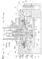
Fig. 5 is a vertical section of the connector module according to the first embodiment, -
Fig. 6 is a vertical section showing a state of connecting a connection target instrument to the connector module relating to the first embodiment, -
Fig. 7 is an exploded perspective view of a connector module according to a second embodiment, -
Fig. 8 is an exploded perspective view of the connector module according to the second embodiment, and -
Fig. 9 is a vertical section of the connector module according to the second embodiment. - Next, embodiments of a connector module relating to the present disclosure will be explained with reference to the accompanying drawings.
In this embodiment, as schematically shown inFig. 1 , there will be explained, as an example thereof, aconnector module 10 to be used in a camera unit 100 (vehicle-mounted camera) configured to be mounted in a vehicle. It is understood, however, that the invention is not limited to the following embodiments, but various modifications will be possible within a range not deviating from the essence thereof. - As shown in
Fig. 1 , thecamera unit 100 includes a camera module 110 (an example of "connection target instrument"), theconnector module 10 and an insulatormain body case 9 formed of a resin or the like for accommodating thecamera module 110 therein. Thecamera module 110 includes, at least, animage sensor 101, anelectronic circuit 102 for controlling driving of theimage sensor 101 and processing image signals outputted from theimage sensor 101, and anoptical system 104 having alens 103 for condensing light onto theimage sensor 101. Thiscamera unit 100 can be used also for other applications than vehicle mounting application (e.g. can be mounted on a bicycle, a drone, etc.) - The
camera unit 100 is electrically connected to an image processing device (not shown) or a monitor device (not shown) via acoaxial cable 120. Thecoaxial cable 120 is a cable configured such that an inner conductor and an outer conductor are arranged coaxially across a dielectric (insulator) therebetween. The inner conductor is responsible for signal transmission and the outer conductor functions as a shield for suppressing influence of electromagnetic waves to the inner conductor. In this embodiment, the inner conductor is responsible also for supplying power from the image processing device or the monitor device to theimage sensor 101 and theelectronic circuit 102 of thecamera unit 100 and also for outputting video signals outputted from theimage sensor 101 and theelectronic circuit 102 to the image processing device and the monitor device. - The
image sensor 101 of thecamera module 110 is a CCD (Charge Coupled Device) sensor or a CIS (CMOS Image Sensor). Thelens 103 is not limited to a single sheet of lens, but may be plurality of sheets of lens. Theelectronic circuit 102 includes a clock driver for driving theimage sensor 101, an A/D converter for converting analog signals outputted from theimage sensor 101 to digital signals, and so on. - The
electronic circuit 102 is configured as a circuit board including electronic devices or components mounted on a signal or a plurality of printed boards. In this, a flexible board may be used for electrical connection between adjacent circuit boards. On the circuit board on which theelectronic circuit 102 is formed, a receptacle A (seeFig. 5 ) is mounted. Theconnector module 10 is electrically connected not only to the receptacle A, but also electrically connected to thecoaxial cable 120 to establish electrical connection between theelectronic circuit 102 and thecoaxial cable 120. -
Fig. 2 shows an overall perspective view of thecamera unit 100.Figs. 3-4 show exploded perspective views of theconnector module 10.Fig. 5 shows a vertical section of theconnector module 10. As shown inFig. 2 , theconnector module 10 includes aconnector case 10A and aconnector 10B inserted in theconnector case 10A. Theconnector case 10A and themain body case 9 are fixed to each other via a plurality of (two in this embodiment) bolts B (an example of "fastener member"). As shown inFig. 3 , theconnector 10B includes ahousing 8, aterminal module 30, anouter seal member 6, ashield case 7 and a rotation-preventing mechanism 5 (an example of "rotation-preventing member"). Further, as shown inFig. 4 , theterminal module 30 includes a center conductor 1 (or a core conductor; an example of "conductor"), aholder 2, atubular shell 3 and aninner seal member 4. Theterminal module 30 has similar functions to those of thecoaxial cable 120 described above. Thecenter conductor 1 corresponds to the inner conductor of thecoaxial cable 120, theholder 2 corresponds to the dielectric (insulator) of thecoaxial cable 120 and thetubular shell 3 corresponds to the outer conductor of thecoaxial cable 120. - As shown in
Fig. 5 , theconnector case 10A is a case for accommodating theconnector 10B, whereas thehousing 8 of theconnector 10B is s case for accommodating theterminal module 30 and theouter seal member 6. As shown inFig. 2 , theconnector case 10A, in thecamera unit 100, is to be located rearwardly of thecamera module 110. For this reason, it may sometimes be called a "rear case". In a like manner, themain body case 9 may sometimes be called a "front case" relative to the rear case in thecamera unit 100. Theconnector case 10A in which thehousing 8 is inserted and fixed and themain body case 9 are fastened to each other via the plurality of bolts B, forming therein an accommodating space for theterminal module 30, theouter seal member 6, theshield case 7, the rotation-preventingmechanism 5 and the receptacle A (see alsoFig. 5 ). - As shown in
Fig. 5 , theshield case 7 shields an inner space E2 of theshield case 7 against electromagnetic waves propagated through an outer space E1 of theshield case 7. More particularly, theshield case 7 covers at least a part of the receptacle A of thecamera module 110, thus shielding theelectronic circuit 102 against the electromagnetic waves such as electromagnetic noise. Thisshield case 7 is connected to the ground (GND) of theelectronic circuit 102. The outer conductor of thecoaxial cable 120 described above is electrically connected to thetubular shell 3. As will be described later herein, theshield case 7 and thetubular shell 3 are electrically connected to each other. Therefore, when theshield case 7 is connected to the ground of theelectronic circuit 102, thetubular shell 3 and the outer conductor of thecoaxial cable 120 are also connected to the ground of theelectronic circuit 102. - Next, with reference to
Figs. 2-6 , theconnector module 10 relating to the first embodiment will be described in greater details. - As described above, the
connector module 10 includes theconnector case 10A and theconnector 10B. Theconnector 10B includes thehousing 8, theterminal module 30, theouter seal member 6, theshield case 7 and the rotation-preventingmechanism 5. Further, theterminal module 30 includes thecenter conductor 1, theholder 2, thetubular shell 3 and theinner seal member 4. - As shown in
Figs. 4-5 , the center (core)conductor 1 is a linear conductor for signal transmission. In this embodiment, thecenter conductor 1 is constituted solely of alinear portion 1a, so the extension direction of thecenter conductor 1 will be referred to as a first direction L herein. Further, the direction orthogonal to the first direction L will be referred to as a radial direction R; and in this radial direction R, the direction toward thecenter conductor 1 will be referred to as a radial inner side R1 and the direction away from thecenter conductor 1 will be referred to as a radial outer side R2, respectively. - The
holder 2 is a cylindrical member comprised of a cylindrical insulator defining at the center thereof athorough hole 23 through which thecenter conductor 1 extends and which supports thecenter conductor 1 inserted therein. Theholder 2 is formed of an insulating material (non-conductive) material such as a resin in order to insulate thecenter conductor 1 from the outside. The length of theholder 2 in the first direction L is shorter than that of thecenter conductor 1. Therefore, theholder 2 supports thecenter conductor 1 by covering acenter portion 14 of thecenter conductor 1 in the first direction L. Namely, opposed ends of thecenter conductor 1 are not covered by theholder 2, but exposed to present a firstterminal portion 11 and a secondterminal portion 12, respectively. The firstterminal portion 11 is disposed on the side of thecoaxial cable 120 and thesecond terminal portion 12 is disposed on the side of the camera module 110 (on the side of the receptacle A). ThoughFig. 4 shows an exploded perspective view for the sake convenience, thecenter conductor 1 is insert-molded in theholder 2. At opposed end portions of thecenter portion 14 covered by theholder 2, there are formed a first annular protrudingportion 14a and a second annular protrudingportion 14b which protrude to the radial outer side R2. With the above-described integral arrangement of forming the annular protrudingportions center portion 14 of thecenter conductor 1 and insert-molding thiscenter portion 14 in theholder 2, accidental detachment of thecenter conductor 1 from theholder 2 can be prevented reliably. Further, as compared with the outside diameter of thecenter portion 14, the respective outside diameters of the firstterminal portion 11 and thesecond terminal portion 12 are set smaller. With this, thelinear portion 1a of thecenter conductor 1 is constituted of the firstterminal portion 11, thesecond terminal portion 12 and thecenter portion 14. Incidentally, in thecenter conductor 1, only either one of the first annular protrudingportion 14a and the second annular protrudingportion 14b may be formed. Further alternatively, the firstterminal portion 11 or thesecond terminal portion 12 may be formed in a curved shape. - At its end portion on the side of the
second terminal portion 12, theholder 2 flares out to the radial outer side R2 toward thesecond terminal portion 12 and includes a plurality of (three in this embodiment) elastically deformable protrudingpieces 22. These protrudingpieces 22 are constituted of cantilever beam-like arms each having a free end on the side of thesecond terminal portion 12. In operation, as theholder 2 is progressively inserted into thetubular shell 3, the protrudingpieces 22 are elastically deformed to the radial inner side R1 and will reach a firstengaging recess portion 31 of thetubular shell 3 to be described later, after which the protrudingpieces 22 will return to the radial outer side R2, whereby engagement is established between the protrudingpieces 22 and the firstengaging recess portion 31 of thetubular shell 3. Thus, assembly between theholder 2 and thetubular shell 3 is easy and also as the engagement between the protrudingpieces 22 and the firstengaging recess portion 31 prevents inadvertent detachment of theholder 2 from thetubular shell 3. - The
tubular shell 3 is a cylindrically shaped conductor member surrounding the radial outer side R2 of theholder 2 and includes atubular end portion 34 protruding from the housing 8 (i.e. not covered by the housing 3). In the inner circumferential face of thistubular end portion 34, there is formed atapered face 34b whose diameter progressively increases toward the opening. Thetubular shell 3 is formed of metal. In thetubular shell 3, there is formed anannular extension portion 33 extending in an annular form from the inner circumferential face to the radial inner side R1. Further, in thetubular shell 3, at a part thereof on the side of thesecond terminal portion 12, there is formed the firstengaging recess portion 31 receded in the annular form from the inner circumferential face to the radial outer side R2. And, as described above, to this firstengaging recess portion 31, the plurality of protrudingpieces 22 of theholder 2 will come into engagement. With this, theholder 2 is fixed to thetubular shell 3. As the bottom side of this firstengaging recess portion 31 is closed, intrusion of electromagnetic noise to theholder 2 side is prevented. The firstengaging recess portion 31 in this embodiment is formed by carrying out a cutting work in the inner circumferential face of thetubular shell 3. Further, in thetubular shell 3, there is also formed a secondengaging recess portion 32 receded in an annular form from the outer circumferential face near the center to the radial inner side R1. As this secondengaging recess portion 32 comes into engagement with a plurality of engagingpawls 81a to be described later of thehousing 8, inadvertent detachment of thetubular shell 3 from thehousing 8 is prevented. Still further, at thetubular end portion 34 of thetubular shell 3, there is formed a thirdengaging recess portion 34a receded in an annular form from the outer circumferential face to the radial inner side R1. - The
inner seal member 4 provides sealing for preventing liquid or the like from entering the inside of theterminal module 30 acting as a coaxial cable. Theinner seal member 4 is an annular-shaped member having elasticity (elastic member). Theinner seal member 4 is mounted in theterminal module 30 such that one side face thereof in the first direction L is retained by theannular extension portion 33 and the other side face thereof is retained by the end face of theholder 2 in the first direction L. - In this way, with the
terminal module 30 as described above, one side of theinner seal member 4 is placed in contact with theannular extension portion 33 and theholder 2 supporting thecenter conductor 1 is placed in contact with the other side of theinner seal member 4 and the protrudingpieces 22 of theholder 2 are engaged with the firstengaging recess portion 31 of thetubular shell 3. In other words, in theterminal module 30, theinner seal member 4 and theholder 2 are disposed at specified positions along the first direction L as being sandwiched between theannular extension portion 33 and the protrudingpieces 22 of theholder 2. Theterminal module 30 configured as above will be assembled with thehousing 8 as being inserted toward a cylindrical space E3 of thehousing 8. - As shown in
Figs. 3 through 5 , thehousing 8 is a case that accommodates theterminal module 30 and theouter seal member 6 and supports the terminal module 30 (tubular shell 3) by inserting this therein. As the outer face of theterminal module 30 is constituted of the conductivetubular shell 3, in order to insulate thetubular shell 3 from the outside of theconnector module 10, thehousing 8 is formed of an insulator (non-conductive) material such as a resin. - The
housing 8 includes a cylindrically-shapedtubular portion 8A and an outercircumferential portion 8B protruding in an annular form from thetubular portion 8A to the radial outer side R2. In the inner circumferential face of thetubular portion 8A, there are provided the plurality of (four in this embodiment) engagingpawls 81a protruding from the base end portions thereof on the firstterminal portion 11 side along the first direction L and protruding, on the leading ends thereof, to the radial inner side R1. As described above, these engagingpawls 81a are engaged with the secondengaging recess portion 32 of thetubular shell 3. The surface of the outercircumferential portion 8B is exposed to be flush with the outer face of theconnector case 10A. Then, by providing e.g. laser welding work in the outercircumferential portion 8B, theconnector case 10A and theconnector 10B (housing 8) will be fixed to each other in a water-tight manner. - The
tubular portion 8A includes, with the outercircumferential portion 8B as a border therebetween, a firstcylindrical portion 81 on the firstterminal portion 11 side along the first direction L and a secondcylindrical portion 82 on thesecond terminal portion 12 side along the first direction L. In the outer circumferential face of the secondcylindrical portion 82, there are formed a plurality of (two in this embodiment) engaging protrudingportions 83 protruding on the radial outer side R2 with which the rotation-preventingmechanism 5 comes into engagement. This engaging producingportion 83 includes a steppedportion 83a with which a second rotation-preventing member 5B to be described later comes into engagement and a protrudingengaging portion 83b further protruding on the radial outer side R2 on the opposed sides (seeFig. 4 ). In the inner circumferential face of the secondcylindrical portion 82, there is formed aseal recess portion 84 in which theouter seal member 6 will be fitted. Thisouter seal member 6 is disposed to come into contact with theseal recess portion 84 acting as the bottom of thehousing 8 in the first direction L. Theouter seal member 6 too is an annular member having elasticity (elastic member), like theinner seal member 4. - The above-described
inner seal member 4 comes into pressed contact with the inner circumferential face of thetubular shell 3 and the outer circumferential face of thecenter conductor 1 and theouter seal member 6 comes into pressed contact with the inner circumferential face of thehousing 8 and the outer circumferential face of thetubular shell 3, thereby to prevent intrusion of liquid to the cylindrical space E3 of thehousing 8. Then, by providing e.g. laser welding work in the outercircumferential portion 8B, theconnector case 10A and theconnector 10B (housing 8) will be fixed to each other in a water-tight manner, thus preventing intrusion of liquid to the inside of theconnector case 10A. In case theconnector module 10 is used in thecamera unit 100 as a vehicle-mounted camera as provided in this embodiment, the sealing using theinner seal member 4 and theouter seal member 6, etc. will be effective. Namely, thecamera unit 100 as a vehicle-mounted camera will often be used for driving or steering assistance or recording traveling conditions. In such case, thecamera unit 100 will often be mounted in a bumper or a door or on the exterior of the vehicle. The exterior of the vehicle will often be subjected to splashing of water or water droplets from rain, snow or a water pool on a road. Therefore, it is advantageous to provide theconnector module 10 with the water-proof property by proving the sealing arrangement described above. - As shown in
Figs. 3-4 , theshield case 7 consists of afirst member 7A and asecond member 7B. Theshield case 7 shields the inner space E2 of theshield case 7 against electromagnetic waves present in the outer space E1 of theshield case 7, e.g. electromagnetic waves such as electromagnetic noises that can influence signals transmitted via thecenter conductor 1, electromagnetic noises that influence e.g. the electronic circuit102 of the camera module 110 (see alsoFig. 5 ). To this end, theshield case 7 too is formed of a conductive material such as a metal. - The
first member 7A is formed like a flat plate having at the center thereof acircular opening portion 73 through which the terminal module 30 (tubular shell 3) extends. In aninner edge portion 73e of this openingportion 73, there are formed a plurality of (six in this embodiment) elastically deformableelastic portions 75 protruding to be bent in the first direction L. As inner ends 75a of these plurality ofelastic portions 75 come into contact with a bottom portion 34a1 and one side wall 34a2 (an example of an outer circumferential portion of the tubular shell 3) of the thirdengaging recess portion 34a, electrical connection is formed (see alsoFig. 5 ). In this embodiment, each one of the plurality ofelastic portions 75 is formed in a trapezoidal shape and are of the identical shape and arranged equidistantly in the circumferential direction. Incidentally, the plurality ofelastic portions 75 may be formed like triangular plates or the like and the shapes and the distances thereof may be varied, thus there are not limitations in these regards. - Further, the
first member 7A includes a plurality of (two for each side, eight in total, in this embodiment) extension members 74 (an example of "elastic piece") extending to be bent toward thesecond member 7B from theouter edge portion 73a of the rectangular flat plate. In this embodiment, each one of the plurality ofextension members 74 is formed like a bar having a curvedleading end portion 74a, these members being of the identical shape. Thisextension member 74 is elastically deformable, with a curved convex face of the curvedleading end portion 74a protruding to be able to contact thesecond member 7B. Namely, with theseextension members 74, a gap G1 is formed between thefirst member 7A and thesecond member 7B (seeFig. 5 ). In this way, as the inner ends 75a of the plurality ofelastic portions 75 come into contact with the outer circumferential portion of thetubular shell 3 and theleading end portions 74a of theextension members 74 come into contact with thesecond member 7B, the electrical connection is established between theshield case 7 and the terminal module 30 (tubular shell 3). Incidentally, the plurality ofextension members 74 are not limited to the above, but may be formed as wide flat plates or the like. - The
second member 7B is a bottomed rectangular tubular case and includes arectangular bottom portion 71 orthogonal to the first direction L along the extension direction of thecenter conductor 1 and aside wall portion 72 bent from the circumference of thebottom portion 71 and extending along the first direction L. At the center of thebottom portion 71, there is formed acircular opening portion 71a through which the terminal module 30 (tubular shell 3) extends, and on the radial inner side R1 of theopening portion 71a of thebottom portion 71, theelastic portion 75 is located and theleading end portion 74a of theextension member 74 comes into contact with the portion of thebottom portion 71 on more radial outer side R2 than the openingportion 71a. In a pair offirst corner portions 71b located on a diagonal line of thebottom portion 71, cutouts are formed. At and through thisfirst corner portion 71b, there is formed apin insertion hole 71c in which a stopper pin P will be inserted for preventing inadvertent withdrawal of thesecond member 7B from theconnector case 10A. Further, in a pair ofsecond corner portions 71d located on the diagonal line different from that of the pair offirst corner portions 71b, there are formed therethrough protrusion insertion holes 71d1 in which stopper protrusions T formed in theconnector case 10A to be described later are to be inserted. Theside wall portions 72 extend vertically along the first direction L in correspondence with the shape of thebottom portion 71. - The rotation-preventing
mechanism 5 includes a first rotation-preventingmember 5A and a second rotation-preventing member 5B. These first rotation-preventingmember 5A and second rotation-preventing member 5B are formed of insulator (non-conductive) material such as a resin. The rotation-preventingmechanism 5 is disposed between theconnector case 10A and theshield case 7 and comes into engagement with thehousing 8, thus preventing rotation of this housing 8 (see alsoFig. 5 ). The first rotation-preventingmember 5A is a ring-like member formed of a pair ofcurved portions 51 and a pair ofstraight portions 52. At the centers of thestraight portions 52, there are formed a pair ofblock portions 52a protruding on the radial outer side R2 and at the centers of the faces of the pair ofblock portions 52a on the side of theconnector case 10A, there are formedgrooves 52b along the radial direction R. The second rotation-preventing member 5B is provided in the form of a ring formed integrally of a pair ofU-shaped members 53 arranged in reverse from each other and joined to each other. In an inner side face of thisU-shaped member 53, there is formed, as a cutout, an engagingrecess portion 53a in which the protruding engagingportion 83b of thehousing 8 described above is engaged; and in outer side faces of a pair of corner portions on a diagonal line of the second rotation-preventing member 5B, there are formeddepression portions 55 depressed in L-shape. - The first rotation-preventing
member 5A prevents rotation of thehousing 8 relative to theconnector case 10A as thegroove 52b of theblock portion 52a is engaged and fixed in position relative to the protruding portion 15b1 of theconnector case 10A to be described later and the engaging protrudingportion 83 of thehousing 8 is placed in opposition to thestraight portion 52. Further, the second rotation-preventing member 5B prevents rotation of thehousing 8 relative to theconnector case 10A as thedepression portion 55 is engaged and fixed in position with a first bulgingportion 15c of theconnector case 10A to be described later and the protruding engagingportion 83b of thehousing 8 is engaged with the engagingrecess portion 53a as being in contact with the steppedportion 83a formed in the secondcylindrical portion 82 of thehousing 8. In this way, thanks to the first rotation-preventingmember 5A and the second rotation-preventing member 5B, rotation of thehousing 8 relative to theconnector case 10A can be prevented in a reliable manner. However, either one of the first rotation-preventingmember 5A and the second rotation-preventing member 5B may be omitted. - As shown in
Fig. 3 , theconnector case 10A is a box-like member having thebottom portion 15 and theside walls 16 formed of an insulator (non-conductive) material such as a resin. In an outer face of thebottom portion 15, there is formed anannular recess portion 15a as an annular-shaped groove in which the outercircumferential portion 8B of thehousing 8 is to be inserted. At the center of thisannular recess portion 15a, there is formed an insertion hole portion 15a1 in which the secondcylindrical portion 82 of thehousing 8 is to be inserted. As described above, when the outercircumferential portion 8B is inserted to theannular recess portion 15a, the surface of the outercircumferential portion 8B will be in flush with the outer face of theconnector case 10A and by providing e.g. a laser welding work in the outercircumferential portion 8B, theconnector case 10A and theconnector 10B (housing 8) are fixed to each other in a water-tight manner. At a pair of corner portions located on a diagonal linee of the outer faces of theside walls 16, there are formed, as cutouts, boltaccommodating portions 16a in which heads of bolts B will be fitted and there are formed therethrough screw holes Ba into which the bolts B are to be threaded. - As shown in
Fig. 4 , in the inner face of thebottom portion 15, there is formed acircumferential groove portion 15b along the outer circumferential face of the first rotation-preventingmember 5A; and at a position of thiscircumferential groove portion 15b corresponding to thegroove 52b of the first rotation-preventingmember 5A, there is formed, as a protrusion, a protruding portion 15b1 engageable with thegroove 52b. At the corner portions located on the diagonal line of the inner faces of theside walls 16, there are formed a pair of first bulgingportions 15c having engaging holes Pa in which the stopper pins P will be engaged. At the corner portions in the inner faces of theside walls 16 located on the different diagonal line from that of the pair of first bulgingportions 15c, there are formed a pair of second bulgingportions 15d having stoper protrusions T engageable with protrusion insertion holes 71d1 of thesecond member 7B. - An assembled finished article in which the
terminal module 30 and theshield case 7 have been accommodated in and fixed to thehousing 8 and theconnector case 10A is a "connector module 10" in a narrow sense of the term. Thisconnector module 10 in the narrow sense of the term with addition of themain body case 9 thereto may be referred to as the "connector module 10" also. In the case of such inclusion of themain body case 9, there is possibility of thecamera module 110 being accommodated in themain body case 9. In this latter case, theconnector module 10 will be understood to be substantially synonymous with thecamera unit 100. Therefore, all of the assembled article of theterminal module 30 and theshield case 7 being accommodated and fixed thehousing 8 and theconnector case 10A, the intermediate assembled article including themain body case 9 additionally, and thecamera unit 100 accommodating thecamera module 110 can be caused to correspond to theconnector module 10. -
Fig. 6 illustrates a mode of electrically connecting thecamera module 110 to the above-described narrowly definedconnector module 10 relating to the first embodiment. As shown inFig. 4 , from the side of the secondcylindrical portion 82 of thehousing 8, theterminal module 30, theouter seal member 6, theconnector case 10A, the first rotation-preventingmember 5A, the second rotation-preventing member 5B, and thefirst member 7A and thesecond member 7B of theshield case 7 will be assembled in this mentioned order and then theshield case 7 will be fixed to theconnector case 10A via the stopper pins P, whereby theconnector module 10 is fabricated. As shown inFig. 6 , thetubular end portion 34 of thetubular shell 3 of thisconnector module 10 will be brought closer to the receptacle A having a conductor Aa electrically connected to the circuit board formed in theelectronic circuit 102. In this, if the axis of the conductor As of the receptacle A is displaced or deviated in the radial direction R relative to the axis of thetubular shell 3, the receptacle A will come into contact with the taperedface 34b formed in the inner circumferential face of thetubular end portion 34 of thetubular shell 3. - And, as the
connector module 10 and the receptacle A are bought further closer to each other, the taperedface 34b and the receptacle A will come into contact with each other; and along the taperedface 34b, theterminal module 30, thehousing 8 and the rotation-preventingmechanism 5 will be moved relative to theconnector case 10A in the radial direction R. Further, due to the actions of the stopper pin P and the stopper protrusion T, thefirst member 7A of theshield case 7 engaged with thetubular shell 3 will move in slidable contact in the radial direction R relative to thesecond member 7B of theshield case 7 fixed to theconnector case 10A. In the course of this, since the curved convex face formed at theleading end portion 74a of theextension member 74 of thefirst member 7A is placed in contact with thesecond member 7B via the gap G1, theterminal module 30, thehousing 8, etc. will be moved smoothly in the radial direction R relative to theconnector case 10A, whereby the axis of thetubular shell 3 and the axis of the conductor Aa of the receptacle will be bought into agreement and both the center conductor 1 (second terminal portion 12) and the conductor Aa will be electrically connected. Under this condition, by providing e.g. a laser welding work in the outercircumferential portion 8B of thehousing 8, theconnector case 10A and theconnector 10B (housing 8) will be fixed and sealed to each other. Finally, theconnector case 10A and themain body case 9 will be fastened to each other via the plurality of bolts B. In this, thesecond member 7B placed in contact with themain body case 9 will be pushed up and theextension members 74 will be elastically deformed in such a manner as to fill the gap G1 between thefirst member 7A and thesecond member 7B, thus rendering the contact between thefirst member 7A and thesecond member 7B more reliable. - In this embodiment, since the
shield case 7 is engaged with thetubular shell 3 via theelastic portions 75, even if there occurs e.g. vibration, the resultant shock can be effectively absorbed by flexible deformation of theelastic portions 75. As a result, the durability of thetubular shell 3 and theshield case 7 can be enhanced. Moreover, theshield case 7 of this embodiment includes thefirst member 7A and thesecond member 7B; and in thefirst member 7A, there are formed the extension members 74 (elastic pieces) as protrusions that can contact thesecond member 7B. Further, in theconnector 10B before theconnector case 10A is fixed to themain body case 9 via the bolts B, the gap G1 is formed between thefirst member 7A and thesecond member 7B by theextension members 74 formed in thefirst member 7A. Namely, with flexible deformation of theextension members 74, thefirst member 7A can move relative to thesecond member 7B. As a result, at the time of attaching the receptacle A to theconnector 10B, even if there is present a positional displacement or deviation between the axes thereof, as thefirst member 7A engaged via theelastic portions 75 with thetubular shell 3 covering thecenter conductor 1 is moved together with thetubular shell 3, positional alignment is made possible with correction of the positional displacement. - Furthermore, when the
connector case 10A is fixed to themain body case 9 via the bolts B, in theconnector 10B, thanks to the elastic deformation of theextension members 74, the gap G1 between thefirst member 7A and thesecond member 7B will be reduced, thus establishing electrical connection between thefirst member 7A and thesecond member 7B. Consequently, theconnector module 10 of this embodiment can maintain high sealing performance. Further, if the elastic pieces are constituted of the plurality ofextension members 74 extending from theouter edge portion 73a of the rectangular-shaped flat plate as described above, theseextension members 74 can be elastically deformed easily and the contact state between thefirst member 7A and thesecond member 7B can be rendered favorable. Moreover, the above arrangement requires only providing theextension members 74 as extensions from theouter edge portion 73a of the flat plate, working of thefirst member 7A is easy. - If the annular shaped outer
circumferential portion 8B fixed to the outer face of theconnector case 10A is formed in thehousing 8 as provided in the instant embodiment, this outercircumferential portion 8B can be easily fixed to theconnector case 10A by laser welding. In addition, even when a load is applied to theconnector 10B due to e.g. vibration, this is received by theconnector case 10A and thehousing 8, so load application between the conductor members (thecenter conductor 1, thetubular shell 3, the shield case 7) of theconnector 10B and theelectronic circuit 102 of thecamera module 110 can be suppressed. Further, with provision of the rotation-preventingmechanism 5 for preventing the rotation of thehousing 8 as provided in the instant embodiment, positioning of thehousing 8 can be carried out reliably and the operation of fixing thehousing 8 with theconnector case 10A can be carried out easily. - Next, with reference to
Figs. 7 through 9 , aconnector module 10 relating to a second embodiment will be explained in details. Incidentally, in the following discussion, those effects, functions and members having similar to those of the first embodiment will be explained with using the same or like reference signs and numerals for the sake of convenience. Theconnector module 10 relating to the second embodiment differs from the first embodiment in that thismodule 10 does not include the rotation-preventingmechanism 5, but includes an annular seal member S. - As shown in
Fig. 9 , theconnector module 10 includes aconnector case 10A and aconnector 10B. Theconnector 10B includes ahousing 8, aterminal module 30, anouter seal member 6, ashield case 7, and an annular seal member S (an example of "seal member"). Further, theterminal module 30 includes acenter conductor 1, aholder 2, atubular shell 3 and aninner seal member 4. - As shown in
Figs. 7-8 , thecenter conductor 1, theholder 2 and theinner seal member 4 relating to this embodiment are identical to those in the first embodiment, so explanation thereof will be omitted. - As shown in
Fig. 9 , thetubular shell 3 is a cylindrically shaped conductive member covering a radial outer side R2 of theholder 2 and includes atubular end portion 34 protruding from thehousing 8. In the inner circumferential face of thistubular end portion 34, there is formed atapered face 34b whose diameter progressively increases toward the opening. Thetubular shell 3 is formed of metal. In thetubular shell 3, at a part thereof on the side of the firstterminal portion 11, there is formed anannular extension portion 33 extending in an annular form from the inner circumferential face to the radial inner side R1. Further, in thetubular shell 3, at a part thereof on the side of thesecond terminal portion 12, there is formed a firstengaging recess portion 31 receded in the annular form from the inner circumferential face to the radial outer side R2. To this firstengaging recess portion 31, a plurality of protrudingpieces 22 of theholder 2 will come into engagement. With this, theholder 2 is fixed to thetubular shell 3. As the bottom side of this firstengaging recess portion 31 is closed, intrusion of electromagnetic noise to theholder 2 side is prevented. The firstengaging recess portion 31 in this embodiment is formed by carrying out a cutting work in the inner circumferential face of thetubular shell 3. Further, in thetubular shell 3, there is formed an annular protrudingportion 35 protruding in an annular form from the outer circumferential face near the center to the radial outer side R2. As this annular protrudingportion 35 and an annular steppedportion 85 of thehousing 8 to be described later are fixed to each other via bonding, welding, etc., inadvertent detachment of thetubular shell 3 from thehousing 8 is prevented. Still further, at thetubular end portion 34 of thetubular shell 3, there is formed a thirdengaging recess portion 34a receded in an annular form from the outer circumferential face to the radial inner side R1. - The
housing 8 is a case that accommodates theterminal module 30 and theouter seal member 6 and supports the terminal module 30 (tubular shell 3) by inserting this therein. As the outer face of theterminal module 30 is constituted of the conductivetubular shell 3, in order to insulate thetubular shell 3 from the outer face of theconnector module 10, thehousing 8 is formed of an insulator (non-conductive) material such as a resin. - The
housing 8 includes atubular portion 8A and an outercircumferential portion 8B protruding in a rectangular form from the end portion of thetubular portion 8A to the radial outer side R2. In the inner circumferential face of thetubular portion 8A, there is formed at the center thereof an annular steppedportion 85 which comes into contact with thetubular shell 3. At the end portion where the outercircumferential portion 8B is formed, there is formed aseal recess portion 84 to which theouter seal member 6 is to be attached. Thisouter seal member 6 is disposed to come into contact with theseal recess portion 84 forming the bottom of thehousing 8 in the first direction L. Theouter seal member 6 too, like theinner seal member 4, is an annular-shaped member having elasticity (elastic member). - As shown in
Fig. 9 , the outercircumferential portion 8B is accommodated in theconnector case 10A and an annular seal member S is provided between the outercircumferential portion 8B and theconnector case 10A. Due to this annular seal member S, a gap G2 is formed between the outercircumferential portion 8B and theconnector case 10A. And, when theconnector case 10A and themain body case 9 are fixed to each other via bolts B (not shown, seeFig. 1 and5 relating to the first embodiment), the annular seal member S is compressed, thus fixing theconnector case 10A and theconnector 10B (housing 8) in a water-tight manner. Further, as shown inFigs. 7-8 , cutouts are formed in a pair of corner portions located on a diagonal line of the outercircumferential portion 8B and in a pair of corner portions located on a diagonal different from the above-described angular portions, there are formed protruding throughholes 8a in which stopper protrusions T formed in theconnector case 10A to be described later are to be fitted. The protruding throughhole 8a has an inside diameter greater than the outside diameter of the stopper protrusion T, so that thehousing 8 is movable relative to theconnector case 10A. Incidentally, if it is desired to secure theconnector case 10A to thehousing 8 firmly, laser welding will be possible with forming theconnector case 10A of a transparent material. - The
shield case 7 consists of afirst member 7A and asecond member 7B. Theshield case 7 shields an inner space E2 of theshield case 7 against electromagnetic waves present in an outer space E1 of theshield case 7, e.g. electromagnetic waves such as electromagnetic noises that can influence signals transmitted via thecenter conductor 1, electromagnetic noises that influence e.g. theelectronic circuit 102 of the camera module 110 (see alsoFig. 9 ). To this end, theshield case 7 too is formed of a conductive material such as a metal. - The
first member 7A is provided in a form of a rectangular flat plate defining, at the center thereof, acircular opening portion 73 through which the terminal module 30 (tubular shell 3) extends. In aninner edge portion 73e of this openingportion 73, there are formed a plurality of (six in this embodiment) elastically deformableelastic portions 75 bent in the first direction L to protrude in a cylindrical form. As each one ofinner ends 75a of these plurality ofelastic portions 75 comes into contact with a bottom portion 34a1 and one side wall 34a2 (an example of the outer circumferential portion of the tubular shell 3) of the thirdengaging recess portion 34a, electrical connection is established (see alsoFig. 9 ). In this embodiment, each one of the plurality ofelastic portions 75 is formed of an identical shape constituted of a trapezoidal plate and theseportions 75 are arranged equidistantly in the circumferential direction. Incidentally, the plurality ofelastic portions 75 may be constituted of e.g. triangular flat plates and the respective shape and spacing may be made different. There are no limitations in these regards. - Further, the
first member 7A includes a plurality of (six in this embodiment) cut pieces 77 (an example of "elastic piece") formed by cutting away parts of the flat plate and bent toward thesecond member 7B. Thecut pieces 77 have theirbase end portions 77a joined via a plurality of throughhole portions 76 formed by cutting away a flat plate in U-shape and arranged radially. In this embodiment, the plurality ofcut pieces 77 are of an identical shape with curvedleading end portions 77b. Thiscut piece 77 is configured to be elastically deformable, so that a curved convex face of the curvedleading end portion 77b is formed to protrude to be able to come into contact with thesecond member 7B. Namely, with thesecut pieces 77, there is formed a gap G1 between thefirst member 7A and thesecond member 7B (see alsoFig. 9 ). In this way, as the inner ends 77a of the plurality ofelastic portions 75 come into contact with the outer circumferential portion of thetubular shell 3 and theleading end portions 77b of thecut pieces 77 come into contact with thesecond member 7B, theshield case 7 and the terminal module 30 (tubular shell 3) are electrically connected to each other. - The
second member 7B has a same arrangement except for omission of thepin insertion hole 71c relating to the first embodiment. Therefore, explanation thereof will be omitted. - As shown in
Figs. 7-9 , the annular seal member S is a circular annular member (elastic member) having elasticity and providing shielding against intrusion of liquid or the like to the inside of theconnector case 10A. In an outer circumferential portion on the radial outer side R2 of the annular seal member S, there is formed a first annular protruding portion Sa that comes into pressed contact with the outer circumferential side of the outercircumferential portion 8B of thehousing 8 and the outer circumferential side of a sealaccommodating recess portion 15e of theconnector case 10A to be described later. Further, in an inner circumferential portion on the radial inner side R1 of the annular seal member S, there is formed a second annular protruding portion Sb that comes into pressed contact with the inner circumferential side of the outercircumferential portion 8B of thehousing 8 and the inner circumferential side of the sealaccommodating recess portion 15e of theconnector case 10A. These portions, i.e. the first annular protruding portion Sa and the second annular protruding portion Sb, are arranged in a common plane in the radial direction R. By providing separately the first annular protruding portion Sa and the second annular protruding portion Sb, even when one of the annular protruding portions Sa, Sb is deformed to invite deterioration in the water-proof performance, the water-proof function can be maintained by the other one of the annular protruding portions Sa, Sb. - The
connector case 10A is a box-like member having thebottom portion 15 and theside walls 16 formed of an insulator (non-conductive) material such as a resin. At the center of thebottom portion 15, there is formed an insertion hole portion 15a1 in which thetubular portion 8A of thehousing 8 is to be inserted. At a pair of corner portions located on a diagonal line of the outer faces of theside walls 16, there are formed, as cutouts, boltaccommodating portions 16a in which heads of bolts B will be fitted and there are formed therethrough screw holes Ba into which the bolts B will be threaded. - As shown in
Fig. 8 , in the inner face of thebottom portion 15, there is formed the sealaccommodating recess portion 15e as a circumferential groove for accommodating the annular seal member S. In the inner face of theside wall 16 and at a pair of corner portions located on a diagonal line different from thebolt accommodating portion 16a, there are formed stopper protrusions T engageable with the protruding insertion holes 71d1 of thesecond member 7B. - As shown in
Fig. 9 , in this embodiment too, if the axis of the receptacle A is displaced or deviated in the radial direction R from the axis of thetubular shell 3, theterminal module 30 and thehousing 8 will move relative to theconnector case 10A in the radial direction R. Further, thefirst member 7A of theshield case 7 engaged with thetubular shell 3 will move in slidable contact in the radial direction R relative to thesecond member 7B of theshield case 7 fixed to theconnector case 10A with the stopper protrusions T. In this, the curved convex face formed at aleading end portion 77b of acut piece 77 of thefirst member 7A will come into contact with thesecond member 7B via a gap G1 and as the gap G2 is formed by the annular seal member S between the outercircumferential portion 8B of thehousing 8 and theconnector case 10A, theterminal module 30 and thehousing 8 will smoothly move relative to theshield case 7 in the radial direction R and the axis of thetubular shell 3 and the axis of the conductor Aa of the receptacle A will be brought into agreement with each other and electrical connection will be established for both the center conductor 1 (second terminal portion 12) and the conductor Aa. Lastly, theconnector case 10A and themain body case 9 will be fastened to each other via the plurality of bolts B. As a result, theextension members 74 will be elastically deformed in such a manner as to fill the gap G1 between thefirst member 7A and thesecond member 7B and the annular seal member S will be compressed in such a manner as to fill the gap G2 between the outercircumferential portion 8B of thehousing 8 and theconnector case 10A, whereby the contact between thefirst member 7A and thesecond member 7B is rendered reliable and the desired water-proof performance is maintained also. - If the elastic pieces are constituted of a plurality of
cut pieces 77 formed radially in the flat plate of thefirst member 7A as so provided in this embodiment, thecut pieces 77 can be elastically deformed easily and the contact state between thefirst member 7A and thesecond member 7B is rendered favorable. Moreover, by providing the throughhole portion 76 within a minimum area, it becomes also possible to secure a larger flat plate area for thefirst member 7A and a larger area for the contact between thefirst member 7A and thesecond member 7B. Further, as thecut piece 77 is formed within the flat plate of thefirst member 7A, it becomes possible to improve the yield of material to form the first member. 7A. The other functions and effects are same as those of the first embodiment, thus explanation thereof being omitted. -
- (1) The
shield case 7 in the first embodiment and theshield case 7 in the second embodiment differ in the shape of thefirst member 7A. However, eitherfirst member 7A may be employed in both the embodiments. - (2) In the foregoing embodiment, the inner ends 75a of the
elastic portions 75 are brought into contact with the bottom portion 34a1 and the one side wall 34a2 of the thirdengaging recess portion 34a. In addition, the center portions of theelastic portions 75 too may be brought into contact with the bottom portion 34a1 of the thirdengaging recess portion 34a, and the contact portion between theelastic portions 75 and the thirdengaging recess portion 34a is not particularly limited. Moreover, theelastic portion 75 may be bent from theinner edge portion 73e to protrude in the opposite direction to the side wall portion 72 (direction opposite to the inner space E2 of the shield case 7). - (3) With omission of the rotation-preventing
mechanism 5 used in the first embodiment, a positioning protrusion or the like maybe provided in the outercircumferential portion 8B of thehousing 8. - (4) In the
housing 8 described above, thetubular portion 8A was formed cylindrical. Instead, it may be formed like an angular tube having a polygonal cross section. Further, in thehousing 8 relating to the first embodiment, the outercircumferential portion 8B was formed like a circular ring. However, it may be formed polygonal. Also, in thehousing 8 relating to the second embodiment, the outercircumferential portion 8B was formed rectangular, but this may be formed like a circular ring or like a polygonal shape other than the rectangular shape. - (5) The
connector module 10 described above is not limited to a coaxial connector, but maybe a multiple-pole differential connector.
Claims (6)
- A connector module (10) configured to be electrically connected to a connection target instrument (110), the connector module (10) comprising:a connector case (10A) to be fixed to a main body case (9) of the connection target instrument (110) via a fastener member (B);a connector (10B) inserted in the connector case (10A);the connector (10B) including a conductive contact (1), an insulator holder (2) supporting the contact (1) inserted therein, a conductive tubular shell (3) surrounding the outer side of the holder (2), an insulator housing (8) supporting the tubular shell (3) inserted therein, and a conductive shield case (7) engageable with the tubular shell (3) for shielding against external electromagnetic waves;the shield case (7) including a first member (7A) having an elastic portion (75) to come into contact with an outer circumferential portion of the tubular shell (3) protruding from the housing (8) and a second member (7B) in the form of a bottomed tube coming into contact with the first member (7A);the first member (7A) forming an elastic piece (74) contactable with the second member (7B); andfixing of the connector case (10A) to the main body case (9) via the fastener member (B) causing, in the connector (10B), elastic deformation of the elastic piece (74), resulting in decrease in a gap (G1) between the first member (7A) and the second member (7B), consequently in establishment of electrical connection between the first member (7A) and the second member (7B).
- The connector module (10) of claim 1, wherein the elastic piece (74) extends from an outer edge portion of the first member (7A).
- The connector module (10) of claim 1, wherein the elastic piece (74) is formed by cutting out a part of the first member (7A).
- The connector module (10) of any one of claims 1-3, wherein the housing (8) includes an outer circumferential portion (8B) that protrudes to the outer side and that is fixed to the outer face of the connector case (10A).
- The connector module (10) of claim 4, wherein between the connector case (10A) and the shield case (7), there is provided a rotation-preventing member (5) engageable with the housing (8) for preventing rotation of the housing (8).
- The connector module (10) of any one of claims 1-3, wherein:the housing (8) includes an outer circumferential portion (8B) that protrudes to the outer side and that is fixed to the inner face of the connector case (10A); andthere is provided a seal member (S) capable of forming a gap (G2) between the connector case (10A) and the outer circumferential portion (8B).
Applications Claiming Priority (1)
| Application Number | Priority Date | Filing Date | Title |
|---|---|---|---|
| JP2020069272A JP2021166161A (en) | 2020-04-07 | 2020-04-07 | Connector module |
Publications (1)
| Publication Number | Publication Date |
|---|---|
| EP3893333A1 true EP3893333A1 (en) | 2021-10-13 |
Family
ID=75302247
Family Applications (1)
| Application Number | Title | Priority Date | Filing Date |
|---|---|---|---|
| EP21165791.1A Withdrawn EP3893333A1 (en) | 2020-04-07 | 2021-03-30 | Connector module |
Country Status (4)
| Country | Link |
|---|---|
| US (1) | US11515673B2 (en) |
| EP (1) | EP3893333A1 (en) |
| JP (1) | JP2021166161A (en) |
| CN (1) | CN113497392A (en) |
Families Citing this family (32)
| Publication number | Priority date | Publication date | Assignee | Title |
|---|---|---|---|---|
| EP3923421A1 (en) * | 2020-06-09 | 2021-12-15 | Afag Holding AG | Electrical connecting device with a base body and a sliding body |
| JP7128237B2 (en) * | 2020-07-29 | 2022-08-30 | 矢崎総業株式会社 | waterproof connector |
| JP7280558B2 (en) * | 2020-10-12 | 2023-05-24 | Smk株式会社 | Floating structure of coaxial connector |
| WO2022092224A1 (en) * | 2020-10-29 | 2022-05-05 | イリソ電子工業株式会社 | Connector |
| TWM615534U (en) * | 2021-04-07 | 2021-08-11 | 帛江科技股份有限公司 | Coaxial connector |
| CN115224521B (en) * | 2021-04-19 | 2024-12-03 | 上海莫仕连接器有限公司 | Floating connector and combination thereof |
| WO2022244165A1 (en) * | 2021-05-19 | 2022-11-24 | 山一電機株式会社 | Connector, connector assembly, camera module, and assembly method |
| JP7004190B1 (en) * | 2021-07-21 | 2022-01-21 | Smk株式会社 | Coaxial connector with floating mechanism |
| CN115939863B (en) * | 2021-08-05 | 2025-11-25 | 上海莫仕连接器有限公司 | Floating connectors and their combinations |
| TWI820479B (en) * | 2021-09-07 | 2023-11-01 | 明泰科技股份有限公司 | Floating electrical connector and circuit connection structure |
| JP7748863B2 (en) * | 2021-12-07 | 2025-10-03 | 日本航空電子工業株式会社 | Floating connector and floating connector assembly |
| CN217239921U (en) * | 2022-01-22 | 2022-08-19 | 富士康(昆山)电脑接插件有限公司 | Connector assembly |
| JP7805826B2 (en) * | 2022-03-14 | 2026-01-26 | ホシデン株式会社 | Connector Module |
| JP7854318B2 (en) * | 2022-03-22 | 2026-05-01 | 日本航空電子工業株式会社 | Floating connector |
| TWI835107B (en) * | 2022-04-01 | 2024-03-11 | 佳必琪國際股份有限公司 | Waterproof structure of socket connector |
| JP7757877B2 (en) * | 2022-05-27 | 2025-10-22 | 株式会社オートネットワーク技術研究所 | connector |
| TWI829254B (en) * | 2022-07-20 | 2024-01-11 | 群光電子股份有限公司 | Connector |
| CN117638555A (en) * | 2022-08-19 | 2024-03-01 | 上海莫仕连接器有限公司 | Electric connector |
| JP7570796B2 (en) * | 2022-09-14 | 2024-10-22 | 矢崎総業株式会社 | Connection direction changeable connector and wire harness |
| JP7822289B2 (en) | 2022-09-27 | 2026-03-02 | ホシデン株式会社 | Connector Module |
| CN120188354A (en) * | 2022-11-16 | 2025-06-20 | 星电株式会社 | Connector modules |
| JP2024084929A (en) | 2022-12-14 | 2024-06-26 | タイコエレクトロニクスジャパン合同会社 | connector |
| JP2024084928A (en) | 2022-12-14 | 2024-06-26 | タイコエレクトロニクスジャパン合同会社 | connector |
| JP2024111717A (en) | 2023-02-06 | 2024-08-19 | タイコエレクトロニクスジャパン合同会社 | Connector Assembly |
| CN116531027B (en) * | 2023-06-08 | 2025-11-11 | 声索生物科技(上海)有限公司 | Self-correcting device of transmission shaft and ultrasonic probe |
| JP7396529B1 (en) * | 2023-07-19 | 2023-12-12 | Smk株式会社 | Rear case for in-vehicle camera and case for in-vehicle camera |
| JP2025074784A (en) * | 2023-10-30 | 2025-05-14 | パナソニックオートモーティブシステムズ株式会社 | In-vehicle cameras |
| JP7442728B1 (en) * | 2023-12-14 | 2024-03-04 | Smk株式会社 | Method for fixing a terminal module to a case housing an electronic device and structure for fixing a terminal module to a case housing an electronic device |
| JP2025098729A (en) * | 2023-12-20 | 2025-07-02 | パナソニックオートモーティブシステムズ株式会社 | In-vehicle camera |
| DE102024101263A1 (en) * | 2024-01-17 | 2025-07-17 | Te Connectivity Solutions Gmbh | Connector assembly for coaxial connectors |
| US20250390005A1 (en) * | 2024-06-21 | 2025-12-25 | Amphenol Corporation | Direct cable connection for automotive cameras |
| CN121602125A (en) * | 2024-08-20 | 2026-03-03 | 泰科电子(上海)有限公司 | Connector housing assembly and coaxial connector |
Citations (8)
| Publication number | Priority date | Publication date | Assignee | Title |
|---|---|---|---|---|
| JP2007127206A (en) | 2005-11-04 | 2007-05-24 | Yazaki Corp | Seal device, seal structure, and connector with seal device |
| JP2014137913A (en) | 2013-01-17 | 2014-07-28 | Smk Corp | Floating connector |
| WO2017125164A1 (en) * | 2016-01-22 | 2017-07-27 | Rosenberger Hochfrequenztechnik Gmbh & Co. Kg | Camera module |
| EP3264537A1 (en) * | 2016-07-01 | 2018-01-03 | Hosiden Corporation | Connector module and vehicle-mounted camera using such module |
| EP3343705A1 (en) * | 2016-12-27 | 2018-07-04 | Hosiden Corporation | Receptacle connector and camera unit |
| US20180287306A1 (en) * | 2015-12-09 | 2018-10-04 | Connaught Electronics Ltd. | Camera with a housing for shielding electromagnetic radiation and motor vehicle |
| JP2019067740A (en) | 2017-10-02 | 2019-04-25 | ホシデン株式会社 | Connector module and on-vehicle camera using the same |
| US10601191B2 (en) * | 2017-10-02 | 2020-03-24 | Hosiden Corporation | Connector module and onboard camera using the same |
Family Cites Families (1)
| Publication number | Priority date | Publication date | Assignee | Title |
|---|---|---|---|---|
| CN119812865A (en) * | 2017-09-27 | 2025-04-11 | 泰科电子(上海)有限公司 | Cable Assemblies and Electrical Connectors |
-
2020
- 2020-04-07 JP JP2020069272A patent/JP2021166161A/en active Pending
-
2021
- 2021-03-30 US US17/216,938 patent/US11515673B2/en active Active
- 2021-03-30 EP EP21165791.1A patent/EP3893333A1/en not_active Withdrawn
- 2021-04-01 CN CN202110354880.2A patent/CN113497392A/en active Pending
Patent Citations (8)
| Publication number | Priority date | Publication date | Assignee | Title |
|---|---|---|---|---|
| JP2007127206A (en) | 2005-11-04 | 2007-05-24 | Yazaki Corp | Seal device, seal structure, and connector with seal device |
| JP2014137913A (en) | 2013-01-17 | 2014-07-28 | Smk Corp | Floating connector |
| US20180287306A1 (en) * | 2015-12-09 | 2018-10-04 | Connaught Electronics Ltd. | Camera with a housing for shielding electromagnetic radiation and motor vehicle |
| WO2017125164A1 (en) * | 2016-01-22 | 2017-07-27 | Rosenberger Hochfrequenztechnik Gmbh & Co. Kg | Camera module |
| EP3264537A1 (en) * | 2016-07-01 | 2018-01-03 | Hosiden Corporation | Connector module and vehicle-mounted camera using such module |
| EP3343705A1 (en) * | 2016-12-27 | 2018-07-04 | Hosiden Corporation | Receptacle connector and camera unit |
| JP2019067740A (en) | 2017-10-02 | 2019-04-25 | ホシデン株式会社 | Connector module and on-vehicle camera using the same |
| US10601191B2 (en) * | 2017-10-02 | 2020-03-24 | Hosiden Corporation | Connector module and onboard camera using the same |
Also Published As
| Publication number | Publication date |
|---|---|
| CN113497392A (en) | 2021-10-12 |
| JP2021166161A (en) | 2021-10-14 |
| US11515673B2 (en) | 2022-11-29 |
| US20210313746A1 (en) | 2021-10-07 |
Similar Documents
| Publication | Publication Date | Title |
|---|---|---|
| US11515673B2 (en) | Electrical connector module with shielding members engaging upon connection to a mating connector | |
| US11757236B2 (en) | Shield member, shield unit, and connector module | |
| EP3462550B1 (en) | Connector module and onboard camera using the same | |
| US11967791B2 (en) | Coaxial connector | |
| US11569611B2 (en) | Connector assembly with an intermediate insulating member and a potting material that fills a portion in an outer conductor more on the front side than on the front surface of the intermediate insulating member | |
| EP3264537B1 (en) | Connector module and vehicle-mounted camera using such module | |
| EP2808694B1 (en) | Ultrasonic wave device | |
| JP2019067740A (en) | Connector module and on-vehicle camera using the same | |
| JP6749232B2 (en) | Receptacle connector and camera unit | |
| JP2018107035A (en) | Receptacle connector and connector | |
| EP3886545B1 (en) | Housing and electronic device | |
| JP6343494B2 (en) | connector | |
| US11228150B2 (en) | Connector and electronic device | |
| CN212460629U (en) | Automobile data recorder | |
| EP4618574A1 (en) | Camera module | |
| KR20240068502A (en) | Camera modure for vehicle | |
| KR20210082427A (en) | Camera module | |
| JP2003086304A (en) | connector |
Legal Events
| Date | Code | Title | Description |
|---|---|---|---|
| PUAI | Public reference made under article 153(3) epc to a published international application that has entered the european phase |
Free format text: ORIGINAL CODE: 0009012 |
|
| STAA | Information on the status of an ep patent application or granted ep patent |
Free format text: STATUS: THE APPLICATION HAS BEEN PUBLISHED |
|
| AK | Designated contracting states |
Kind code of ref document: A1 Designated state(s): AL AT BE BG CH CY CZ DE DK EE ES FI FR GB GR HR HU IE IS IT LI LT LU LV MC MK MT NL NO PL PT RO RS SE SI SK SM TR |
|
| STAA | Information on the status of an ep patent application or granted ep patent |
Free format text: STATUS: THE APPLICATION IS DEEMED TO BE WITHDRAWN |
|
| 18D | Application deemed to be withdrawn |
Effective date: 20220414 |