EP3893322A1 - Secondary battery - Google Patents
Secondary battery Download PDFInfo
- Publication number
- EP3893322A1 EP3893322A1 EP19950389.7A EP19950389A EP3893322A1 EP 3893322 A1 EP3893322 A1 EP 3893322A1 EP 19950389 A EP19950389 A EP 19950389A EP 3893322 A1 EP3893322 A1 EP 3893322A1
- Authority
- EP
- European Patent Office
- Prior art keywords
- negative electrode
- positive electrode
- pouch
- tabs
- electrode tabs
- Prior art date
- Legal status (The legal status is an assumption and is not a legal conclusion. Google has not performed a legal analysis and makes no representation as to the accuracy of the status listed.)
- Granted
Links
Images




Classifications
-
- H—ELECTRICITY
- H01—ELECTRIC ELEMENTS
- H01M—PROCESSES OR MEANS, e.g. BATTERIES, FOR THE DIRECT CONVERSION OF CHEMICAL ENERGY INTO ELECTRICAL ENERGY
- H01M50/00—Constructional details or processes of manufacture of the non-active parts of electrochemical cells other than fuel cells, e.g. hybrid cells
- H01M50/50—Current conducting connections for cells or batteries
- H01M50/531—Electrode connections inside a battery casing
- H01M50/54—Connection of several leads or tabs of plate-like electrode stacks, e.g. electrode pole straps or bridges
-
- H—ELECTRICITY
- H01—ELECTRIC ELEMENTS
- H01M—PROCESSES OR MEANS, e.g. BATTERIES, FOR THE DIRECT CONVERSION OF CHEMICAL ENERGY INTO ELECTRICAL ENERGY
- H01M10/00—Secondary cells; Manufacture thereof
- H01M10/05—Accumulators with non-aqueous electrolyte
- H01M10/052—Li-accumulators
-
- H—ELECTRICITY
- H01—ELECTRIC ELEMENTS
- H01M—PROCESSES OR MEANS, e.g. BATTERIES, FOR THE DIRECT CONVERSION OF CHEMICAL ENERGY INTO ELECTRICAL ENERGY
- H01M10/00—Secondary cells; Manufacture thereof
- H01M10/05—Accumulators with non-aqueous electrolyte
- H01M10/058—Construction or manufacture
- H01M10/0585—Construction or manufacture of accumulators having only flat construction elements, i.e. flat positive electrodes, flat negative electrodes and flat separators
-
- H—ELECTRICITY
- H01—ELECTRIC ELEMENTS
- H01M—PROCESSES OR MEANS, e.g. BATTERIES, FOR THE DIRECT CONVERSION OF CHEMICAL ENERGY INTO ELECTRICAL ENERGY
- H01M50/00—Constructional details or processes of manufacture of the non-active parts of electrochemical cells other than fuel cells, e.g. hybrid cells
- H01M50/10—Primary casings; Jackets or wrappings
- H01M50/102—Primary casings; Jackets or wrappings characterised by their shape or physical structure
- H01M50/105—Pouches or flexible bags
-
- H—ELECTRICITY
- H01—ELECTRIC ELEMENTS
- H01M—PROCESSES OR MEANS, e.g. BATTERIES, FOR THE DIRECT CONVERSION OF CHEMICAL ENERGY INTO ELECTRICAL ENERGY
- H01M50/00—Constructional details or processes of manufacture of the non-active parts of electrochemical cells other than fuel cells, e.g. hybrid cells
- H01M50/10—Primary casings; Jackets or wrappings
- H01M50/172—Arrangements of electric connectors penetrating the casing
- H01M50/174—Arrangements of electric connectors penetrating the casing adapted for the shape of the cells
- H01M50/178—Arrangements of electric connectors penetrating the casing adapted for the shape of the cells for pouch or flexible bag cells
-
- H—ELECTRICITY
- H01—ELECTRIC ELEMENTS
- H01M—PROCESSES OR MEANS, e.g. BATTERIES, FOR THE DIRECT CONVERSION OF CHEMICAL ENERGY INTO ELECTRICAL ENERGY
- H01M50/00—Constructional details or processes of manufacture of the non-active parts of electrochemical cells other than fuel cells, e.g. hybrid cells
- H01M50/10—Primary casings; Jackets or wrappings
- H01M50/183—Sealing members
-
- H—ELECTRICITY
- H01—ELECTRIC ELEMENTS
- H01M—PROCESSES OR MEANS, e.g. BATTERIES, FOR THE DIRECT CONVERSION OF CHEMICAL ENERGY INTO ELECTRICAL ENERGY
- H01M50/00—Constructional details or processes of manufacture of the non-active parts of electrochemical cells other than fuel cells, e.g. hybrid cells
- H01M50/20—Mountings; Secondary casings or frames; Racks, modules or packs; Suspension devices; Shock absorbers; Transport or carrying devices; Holders
-
- H—ELECTRICITY
- H01—ELECTRIC ELEMENTS
- H01M—PROCESSES OR MEANS, e.g. BATTERIES, FOR THE DIRECT CONVERSION OF CHEMICAL ENERGY INTO ELECTRICAL ENERGY
- H01M50/00—Constructional details or processes of manufacture of the non-active parts of electrochemical cells other than fuel cells, e.g. hybrid cells
- H01M50/50—Current conducting connections for cells or batteries
- H01M50/543—Terminals
- H01M50/547—Terminals characterised by the disposition of the terminals on the cells
- H01M50/55—Terminals characterised by the disposition of the terminals on the cells on the same side of the cell
-
- H—ELECTRICITY
- H01—ELECTRIC ELEMENTS
- H01M—PROCESSES OR MEANS, e.g. BATTERIES, FOR THE DIRECT CONVERSION OF CHEMICAL ENERGY INTO ELECTRICAL ENERGY
- H01M50/00—Constructional details or processes of manufacture of the non-active parts of electrochemical cells other than fuel cells, e.g. hybrid cells
- H01M50/50—Current conducting connections for cells or batteries
- H01M50/543—Terminals
- H01M50/552—Terminals characterised by their shape
- H01M50/553—Terminals adapted for prismatic, pouch or rectangular cells
- H01M50/557—Plate-shaped terminals
-
- H—ELECTRICITY
- H01—ELECTRIC ELEMENTS
- H01M—PROCESSES OR MEANS, e.g. BATTERIES, FOR THE DIRECT CONVERSION OF CHEMICAL ENERGY INTO ELECTRICAL ENERGY
- H01M50/00—Constructional details or processes of manufacture of the non-active parts of electrochemical cells other than fuel cells, e.g. hybrid cells
- H01M50/40—Separators; Membranes; Diaphragms; Spacing elements inside cells
- H01M50/463—Separators, membranes or diaphragms characterised by their shape
-
- Y—GENERAL TAGGING OF NEW TECHNOLOGICAL DEVELOPMENTS; GENERAL TAGGING OF CROSS-SECTIONAL TECHNOLOGIES SPANNING OVER SEVERAL SECTIONS OF THE IPC; TECHNICAL SUBJECTS COVERED BY FORMER USPC CROSS-REFERENCE ART COLLECTIONS [XRACs] AND DIGESTS
- Y02—TECHNOLOGIES OR APPLICATIONS FOR MITIGATION OR ADAPTATION AGAINST CLIMATE CHANGE
- Y02E—REDUCTION OF GREENHOUSE GAS [GHG] EMISSIONS, RELATED TO ENERGY GENERATION, TRANSMISSION OR DISTRIBUTION
- Y02E60/00—Enabling technologies; Technologies with a potential or indirect contribution to GHG emissions mitigation
- Y02E60/10—Energy storage using batteries
-
- Y—GENERAL TAGGING OF NEW TECHNOLOGICAL DEVELOPMENTS; GENERAL TAGGING OF CROSS-SECTIONAL TECHNOLOGIES SPANNING OVER SEVERAL SECTIONS OF THE IPC; TECHNICAL SUBJECTS COVERED BY FORMER USPC CROSS-REFERENCE ART COLLECTIONS [XRACs] AND DIGESTS
- Y02—TECHNOLOGIES OR APPLICATIONS FOR MITIGATION OR ADAPTATION AGAINST CLIMATE CHANGE
- Y02P—CLIMATE CHANGE MITIGATION TECHNOLOGIES IN THE PRODUCTION OR PROCESSING OF GOODS
- Y02P70/00—Climate change mitigation technologies in the production process for final industrial or consumer products
- Y02P70/50—Manufacturing or production processes characterised by the final manufactured product
Definitions
- the present invention relates to a pouch-type secondary battery, and more specifically, to a secondary battery in which a positive electrode lead and a negative electrode lead are positioned at a central portion of a top surface or a bottom surface of a pouch to minimize a size of a sealing part, thereby capable of increasing in capacity to a volume and reducing a current density deviation within an electrode assembly.
- lithium secondary batteries having high energy density and low self-discharge characteristics and capable of maintaining relatively high voltage have been commercialized and widely used, and researches and developments for improving performances of the lithium secondary batteries have been actively conducted.
- the secondary batteries have a structure in which an electrode assembly and an electrolyte are embedded within a case such as a can and a pouch.
- the electrode assembly has a structure in which a positive electrode, a separator, and a negative electrode are repeatedly stacked.
- the electrode assemblies are generally classified into a jelly-roll type and a stacked type. In the jelly-roll type, positive electrodes, separators, and negative electrodes are stacked and rolled to be embedded within a case. In the stacked type, positive electrodes, separators, and negative electrodes are cut into a certain size and stacked.
- a stacked type electrode assembly 2 is manufactured in a hexahedral shape having quadrangular top and bottom surfaces as illustrated in FIG. 1 , and is embedded within a pouch that is divided into an upper part 1a and a lower part 1b.
- the upper part 1a and the lower part 1b of the pouch are sealed by applying heat and a pressure on edge portions (outside a portion displayed as a dotted line on the upper part of the pouch).
- a sealing part at which sealing is performed is disposed on each of the edge portions of the pouch and may unnecessarily occupy a space.
- the sealing part causes an increase in sizes of battery module and battery pack.
- a positive electrode terminal 3b and a negative electrode terminal 4b through which current flows are positioned on one side of the sealing part.
- a current density deviation may increase within the electrode assembly 2 to cause generation of heat and degradation of the electrode.
- a main objective of the present invention is to provide a secondary battery in which the number and surface area of sealing parts are minimized to increase in capacity to a volume, and a positive electrode terminal and a negative electrode terminal are positioned at a central portion to reduce a current density deviation (a difference between a current density in the vicinity of the positive electrode terminal and the negative electrode terminal and a current density in a region away from the positive electrode terminal and the negative electrode terminal) within an electrode assembly.
- the present invention is to provide a secondary battery in which an electrode assembly comprising positive electrodes, of which positive electrode tabs are connected to each other, and negative electrodes, of which negative electrode tabs are connected to each other, is embedded in a pouch
- the secondary battery comprising: the electrode assembly having a quadrangular shape with four sides, wherein a space part that is an empty space is defined between the two sides facing each other, and the positive electrode tabs and the negative electrode tabs are positioned within the space part; a positive electrode lead having one end connected to the positive electrode tabs; a negative electrode lead having one end connected to the negative electrode tabs; and the pouch in which the electrode assembly is embedded, wherein the other end of the positive electrode lead and the other end of the negative electrode lead pass through the pouch to protrude from one of the largest surfaces of the pouch to the outside.
- a hole which passes through both surfaces of the electrode assembly in a thickness direction between the facing two horizontal sides and between the facing two vertical sides, may be defined in the electrode assembly to define the space part.
- Each of the positive electrode tabs positioned within the space part may be spaced a predetermined distance from each of the negative electrode tabs positioned within the space part.
- the hole defining the space part may have a quadrangular shape.
- the pouch may have a quadrangular shape with four sides, wherein only one side is opened in a state in which the three sides are closed so that the electrode assembly is inserted into the pouch, and when the electrode assembly is inserted, the opened side and a portion, through which each of the positive electrode lead and the negative electrode lead protrudes, are sealed.
- the present invention additionally provides a configuration in which two sub-electrode assemblies are provided. That is, the electrode assembly may be constituted by two sub-electrode assemblies, each of which has the positive electrode tabs and the negative electrode tabs protruding from the same side, wherein, in a state in which the positive electrode tabs of the sub-electrode assemblies are disposed to face each other, the facing positive electrode tabs are connected to each other, and in a state in which the negative electrode tabs of the sub-electrode assemblies are disposed to face each other, the facing negative electrode tabs are connected to each other, wherein the sub-electrode assemblies are spaced apart from each other to define a space part between the sub-electrode assemblies.
- bonding of the facing positive electrode tabs and bonding of the facing negative electrode tabs may be performed through thermal fusion using ultrasonic waves in a state in which, when one tab is disposed below the other tab, the other tab is seated on the one tab to surface-contact each other.
- the positive electrode lead when the facing positive electrode tabs are bonded to each other, the positive electrode lead may be bonded together with the positive electrode tabs in a state in which the positive electrode lead is disposed on the uppermost positive electrode tab, and when the facing negative electrode tabs are bonded to each other, the negative electrode lead may be bonded together with the negative electrode tabs in a state in which the negative electrode lead is disposed on the uppermost negative electrode tab.
- the pouch may be constituted by connecting two sub-pouches, into which the sub-electrode assemblies are respectively inserted, to each other.
- Each of the sub-pouches may have a quadrangular shape, wherein, in a state in which only one side, through which the positive electrode tabs and the negative electrode tabs are exposed, is opened, and the three sides are closed, the opened sides of the sub-pouches face each other at a position at which the facing positive electrode tabs of the sub-electrode assemblies are connected to each other, and the facing negative electrode tabs of the sub-electrode assemblies are connected to each other.
- the opened sides may be bonded to each other to seal the inside of the pouch.
- the plurality of secondary batteries having the above-described constituents may be connected to each other to additionally provide a large capacity electric storage device such as a battery module and/or a battery pack.
- the present invention comprising the above-described continents has the structure in which the positive electrode lead and the negative electrode lead pass through the pouch to protrude from one of the largest surfaces (that is, the top surface or the bottom surface) of the pouch to the outside.
- the number and size of the sealing parts in the pouch may be minimized, and the current density deviation within the electrode assembly may be reduced.
- the two sub-electrode assemblies are connected to each other, and the two sub-pouches are connected to each other.
- the sealing part on the edge portion of the pouch may be removed.
- the present invention relates to a secondary battery in which an electrode assembly 20 comprising positive electrodes 23, of which positive electrode tabs 20a are connected to each other, and negative electrodes 25, of which negative electrode tabs 22a are connected to each other, is embedded in a pouch 10.
- a positive electrode lead 20b connected to the positive electrode tabs 20a and a negative electrode lead 22b connected to the negative electrode tabs 22a are positioned at a central portion of the pouch 10 to achieve a reduction in current density deviation.
- FIG. 2 is a perspective view illustrating the inside of a secondary battery according to a first embodiment of the present invention
- FIG. 3 is a perspective view illustrating a state before an electrode assembly is embedded within a pouch.
- an electrode assembly 20 in the embodiment has a quadrangular shape with four sides (that is, side surfaces) and is constituted by repeatedly stacking a positive electrode 23, a separator 24, and a negative electrode 25 as illustrated in FIG. 4 .
- the electrode assembly 20 has a space part 21 that is an empty space defined between relatively short sides (horizontal sides) facing each other and between relatively long sides (vertical sides) facing each other, that is, in a region (a central portion).
- a positive electrode tab 20a protruding from the positive electrode 23 and a negative electrode tab 22a protruding from the negative electrode 25 are disposed within the space part 21. That is, each of the positive electrode 23, the negative electrode 25, and the separator 24 has a structure in which a quadrangular holes is punched at the same position, as illustrated in FIG. 4 , to define the space part 21 when stacked on each other.
- the space part 21 is constituted by stacking the quadrangular holes to pass through both surfaces of the electrode assembly in a thickness direction.
- the negative electrode tabs 22a are merged together after being bent upward, and then bonded to a negative electrode lead 22b.
- the positive electrode tabs 20a are merged together after being bent upward, and then bonded to a positive electrode lead 20b. That is, one end of the positive electrode lead 20b and one end of the negative electrode lead 22b are bonded to the positive electrode tabs 20a and the negative electrode tab 22a, respectively.
- the positive electrode tabs 20a and the negative electrode tabs 22a positioned within the space part 21 are spaced a predetermined distance from each other in a width direction of the electrode assembly 20.
- the pouch 10 has an opened hexahedral shape that has surfaces at the three sides and no surface at one side between a top surface and a bottom surface as illustrated in FIG. 3 .
- a cutoff part 12 having a predetermined length is defined on the top surface (or the bottom surface) of the pouch 10 so that the positive electrode lead and the negative electrode lead protrude outward from the pouch.
- the cutoff part 12 is provided at a position overlapping the inside of the space part 21 of the electrode assembly 20 when the electrode assembly 20 is inserted into the pouch 10, and has a sufficient width and length so that the positive electrode lead 20b and the negative electrode lead 22b protrude.
- the cutoff part 12 and the opened portion of the pouch 10, through which the electrode assembly 20 enters are sealed (by applying heat and a pressure) to define a sealing part S.
- the opened portion through which the electrode assembly 20 enters may be sealed when a pressure is vertically applied in a state in which upper and lower inner surfaces are in contact with each other.
- the cutoff part 12 may be sealed by applying heat and a pressure in a state in which edge portions of the cutoff part 12 are pulled to overlap each other, or may be sealed by applying heat and a pressure in a state in which the cutoff part 12 is covered with a cover (not shown) made of the same material as the pouch 10.
- the sealing may be established by applying an adhesive material that ensures appropriate insulating properties and sealing performance.
- the pouch 10 has the quadrangular hexahedron shape with the four sides between the top surface and the bottom surface. Only the one side surface is opened in a state in which the three side surfaces are closed so that the electrode assembly 20 is inserted. When the electrode assembly 20 is inserted, the opened side surface and the portion, through which the positive electrode lead and the negative electrode lead protrude, are sealed.
- the number of sealing parts may be reduced to increase in volume of the electrode assembly to a total volume, thereby increasing in capacity when compared to the structure having the four sealing parts according to the related art.
- the positive electrode lead 20b and the negative electrode lead 22b protrude outward through the cutoff part 12, and the cutoff part 12 is disposed to be positioned at a central portion of the top surface or the bottom surface of the pouch 10.
- a difference (a current density deviation) between a current density in the vicinity of a positive electrode terminal and a negative electrode terminal and a current density in a region away from the positive electrode terminal and the negative electrode terminal within the electrode assembly may be minimized to increase in charging/discharging efficiency and retard the degradation of the electrodes.
- the secondary battery provided in the embodiment has the constituents and effects which satisfy the objective of the present invention that is intended to provide the secondary battery having the increasing capacity to the volume and the reduced current density deviation.
- two sub-electrode assemblies 40 and 50 are connected to each other to constitute an electrode assembly
- two sub-pouches 30 and 60 are connected to each other to constitute a pouch.
- FIG. 6 is a perspective view illustrating the inside of a secondary battery according to a second embodiment of the present invention
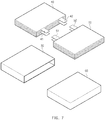
- FIG. 7 is an exploded perspective view of sub-electrode assemblies and sub-pouches.
- a positive electrode, a separator, and a negative electrode are sequentially stacked in each of the sub-electrode assemblies 40 and 50.
- Positive electrode tabs 41 and 51 merged together after protruding from the positive electrodes and negative electrode tabs 42 and 52 merged together after protruding from the negative electrodes protrude from the same side.
- the facing positive electrode tabs 41 and 51 of the sub-electrode assemblies 40 and 50 are disposed to face each other, and the negative electrode tabs 42 and 52 of the sub-electrode assemblies 40 and 50 face each other, the facing positive electrode tabs 41 and 51 are connected to each other, and the facing negative electrode tabs 42 and 52 are connected to each other, as illustrated in FIG. 8 .
- the sub-electrode assemblies 40 and 50 are spaced apart from each other to define a space part 80, and the space part 80 preferably has a minimum size to occupy a small space within the pouch.
- bonding of the facing positive electrode tabs 41 and 51 and bonding of the facing negative electrode tabs 42 and 52 are performed through thermal fusing using ultrasonic waves in a state in which, when one tab is disposed below the other tab, the other tab is seated on the one tab to surface-contact the one tab.
- a positive electrode lead 70a is bonded together with the positive electrode tabs 41 and 51 in a state in which the positive electrode lead is disposed on the uppermost positive electrode tab.
- a negative electrode lead 70b is bonded together with the negative electrode tabs 42 and 52 in a state in which the negative electrode lead is disposed on the upper most negative electrode tab.
- the pouch is constituted by connecting the two sub-pouches 30 and 60, into which the sub-electrode assemblies 40 and 50 are respectively inserted, to each other.
- Each of the sub-pouches 30 and 60 has a quadrangular hexahedron shape.
- the opened sides (the side surfaces) of the sub-pouches 40 and 50 face each other at a position at which the facing positive electrode tabs 41 and 51 of the sub-electrode assemblies are connected to each other, and the facing negative electrode tabs 42 and 52 of the sub-electrode assemblies are connected to each other.
- the opened sides (the side surfaces) are bonded to each other to seal the inside of the pouch.
- the bonding may be performed by applying the heat and pressure in a state in which edge portions are pulled to overlap each other, or may be performed by applying the heat and pressure in a state in which a portion to be bonded is covered with a cover (not shown) made of the same material as the pouch.
- the sealing may be established by applying an adhesive material that ensures insulating properties and sealing performance.
- the positive electrode lead 70a and the negative electrode lead 70b are positioned at a central portion of the pouch, and thus sealing parts disposed along edges of the pouch may be removed. Therefore, a capacity to a volume may increase, and a current density deviation may be reduced when compared to the related art. That is, the secondary battery provided in the embodiment also has the constituents and effects that satisfy the objective of the present invention.
- the positive electrode lead and the negative electrode lead are positioned at the central portion of the largest surface (that is, the top surface or the bottom surface) of the pouch, and thus the capacity to the volume may increase.
- the plurality of secondary batteries are electrically connected to each other to constitute a battery module and/or a battery pack, a size of the secondary battery may be reduced, and connection structures of the negative electrode lead and the positive electrode lead may be simplified.
- the present invention comprising the above-described constituents has the structure in which the positive electrode lead and the negative electrode lead pass through the pouch to protrude from one of the largest surfaces of the pouch to the outside, and thus the number and size of the sealing parts in the pouch may be minimized, and the current density deviation within the electrode assembly may be reduced.
- the two sub-electrode assemblies are connected to each other, and the two sub-pouches are connected to each other.
- the sealing part on the edge portion of the pouch may be removed.
Landscapes
- Chemical & Material Sciences (AREA)
- Chemical Kinetics & Catalysis (AREA)
- Electrochemistry (AREA)
- General Chemical & Material Sciences (AREA)
- Engineering & Computer Science (AREA)
- Manufacturing & Machinery (AREA)
- Connection Of Batteries Or Terminals (AREA)
- Secondary Cells (AREA)
Abstract
Description
- The present invention relates to a pouch-type secondary battery, and more specifically, to a secondary battery in which a positive electrode lead and a negative electrode lead are positioned at a central portion of a top surface or a bottom surface of a pouch to minimize a size of a sealing part, thereby capable of increasing in capacity to a volume and reducing a current density deviation within an electrode assembly.
- Demands of high-efficiency secondary batteries are rapidly increasing in fields of a mobile device, an electric vehicle, or the like. However, among the secondary batteries, lithium secondary batteries having high energy density and low self-discharge characteristics and capable of maintaining relatively high voltage have been commercialized and widely used, and researches and developments for improving performances of the lithium secondary batteries have been actively conducted.
- The secondary batteries have a structure in which an electrode assembly and an electrolyte are embedded within a case such as a can and a pouch. The electrode assembly has a structure in which a positive electrode, a separator, and a negative electrode are repeatedly stacked. The electrode assemblies are generally classified into a jelly-roll type and a stacked type. In the jelly-roll type, positive electrodes, separators, and negative electrodes are stacked and rolled to be embedded within a case. In the stacked type, positive electrodes, separators, and negative electrodes are cut into a certain size and stacked.
- Among the types, a stacked type electrode assembly 2 is manufactured in a hexahedral shape having quadrangular top and bottom surfaces as illustrated in
FIG. 1 , and is embedded within a pouch that is divided into anupper part 1a and alower part 1b. When the electrode assembly 2 is embedded within the pouch, theupper part 1a and thelower part 1b of the pouch are sealed by applying heat and a pressure on edge portions (outside a portion displayed as a dotted line on the upper part of the pouch). - However, as described above, a sealing part at which sealing is performed is disposed on each of the edge portions of the pouch and may unnecessarily occupy a space. Particularly, in a battery module, a battery pack, or the like in which a plurality of secondary batteries are mounted, the sealing part causes an increase in sizes of battery module and battery pack.
- In addition, as illustrated in
FIG. 1 , apositive electrode terminal 3b and anegative electrode terminal 4b through which current flows are positioned on one side of the sealing part. However, in a structure, in which thepositive electrode terminal 3b connected to apositive electrode tab 3a and thenegative electrode terminal 4b connected to anegative electrode tab 4a are disposed to lean toward only one side, a current density deviation may increase within the electrode assembly 2 to cause generation of heat and degradation of the electrode. - Accordingly, a main objective of the present invention is to provide a secondary battery in which the number and surface area of sealing parts are minimized to increase in capacity to a volume, and a positive electrode terminal and a negative electrode terminal are positioned at a central portion to reduce a current density deviation (a difference between a current density in the vicinity of the positive electrode terminal and the negative electrode terminal and a current density in a region away from the positive electrode terminal and the negative electrode terminal) within an electrode assembly.
- To achieve the above-described objects, the present invention is to provide a secondary battery in which an electrode assembly comprising positive electrodes, of which positive electrode tabs are connected to each other, and negative electrodes, of which negative electrode tabs are connected to each other, is embedded in a pouch, the secondary battery comprising: the electrode assembly having a quadrangular shape with four sides, wherein a space part that is an empty space is defined between the two sides facing each other, and the positive electrode tabs and the negative electrode tabs are positioned within the space part; a positive electrode lead having one end connected to the positive electrode tabs; a negative electrode lead having one end connected to the negative electrode tabs; and the pouch in which the electrode assembly is embedded, wherein the other end of the positive electrode lead and the other end of the negative electrode lead pass through the pouch to protrude from one of the largest surfaces of the pouch to the outside.
- A hole, which passes through both surfaces of the electrode assembly in a thickness direction between the facing two horizontal sides and between the facing two vertical sides, may be defined in the electrode assembly to define the space part.
- Each of the positive electrode tabs positioned within the space part may be spaced a predetermined distance from each of the negative electrode tabs positioned within the space part. The hole defining the space part may have a quadrangular shape.
- The pouch may have a quadrangular shape with four sides, wherein only one side is opened in a state in which the three sides are closed so that the electrode assembly is inserted into the pouch, and when the electrode assembly is inserted, the opened side and a portion, through which each of the positive electrode lead and the negative electrode lead protrudes, are sealed.
- Furthermore, the present invention additionally provides a configuration in which two sub-electrode assemblies are provided. That is, the electrode assembly may be constituted by two sub-electrode assemblies, each of which has the positive electrode tabs and the negative electrode tabs protruding from the same side, wherein, in a state in which the positive electrode tabs of the sub-electrode assemblies are disposed to face each other, the facing positive electrode tabs are connected to each other, and in a state in which the negative electrode tabs of the sub-electrode assemblies are disposed to face each other, the facing negative electrode tabs are connected to each other, wherein the sub-electrode assemblies are spaced apart from each other to define a space part between the sub-electrode assemblies.
- Here, bonding of the facing positive electrode tabs and bonding of the facing negative electrode tabs may be performed through thermal fusion using ultrasonic waves in a state in which, when one tab is disposed below the other tab, the other tab is seated on the one tab to surface-contact each other.
- Here, when the facing positive electrode tabs are bonded to each other, the positive electrode lead may be bonded together with the positive electrode tabs in a state in which the positive electrode lead is disposed on the uppermost positive electrode tab, and when the facing negative electrode tabs are bonded to each other, the negative electrode lead may be bonded together with the negative electrode tabs in a state in which the negative electrode lead is disposed on the uppermost negative electrode tab.
- The pouch may be constituted by connecting two sub-pouches, into which the sub-electrode assemblies are respectively inserted, to each other. Each of the sub-pouches may have a quadrangular shape, wherein, in a state in which only one side, through which the positive electrode tabs and the negative electrode tabs are exposed, is opened, and the three sides are closed, the opened sides of the sub-pouches face each other at a position at which the facing positive electrode tabs of the sub-electrode assemblies are connected to each other, and the facing negative electrode tabs of the sub-electrode assemblies are connected to each other. The opened sides may be bonded to each other to seal the inside of the pouch.
- The plurality of secondary batteries having the above-described constituents may be connected to each other to additionally provide a large capacity electric storage device such as a battery module and/or a battery pack.
- The present invention comprising the above-described continents has the structure in which the positive electrode lead and the negative electrode lead pass through the pouch to protrude from one of the largest surfaces (that is, the top surface or the bottom surface) of the pouch to the outside. Thus, the number and size of the sealing parts in the pouch may be minimized, and the current density deviation within the electrode assembly may be reduced.
- Furthermore, according to the present invention, the two sub-electrode assemblies are connected to each other, and the two sub-pouches are connected to each other. Thus, the sealing part on the edge portion of the pouch may be removed.
-
-
FIG. 1 is a perspective view illustrating a state before a pouch is sealed in a pouch-type secondary battery according to the related art. -
FIG. 2 is a perspective view illustrating the inside of a secondary battery according to a first embodiment of the present invention. -
FIG. 3 is a perspective view illustrating a state before an electrode assembly is embedded within a pouch in the secondary battery ofFIG. 2 . -
FIG. 4 is an exploded perspective view of a positive electrode, a separator, and a negative electrode which constitute the electrode assembly according to the first embodiment. -
FIG. 5 is a perspective view illustrating a sealing part S defined in the secondary battery according to the first embodiment. -
FIG. 6 is a perspective view illustrating the inside of a secondary battery according to a second embodiment of the present invention. -
FIG. 7 is an exploded perspective view of sub-electrode assemblies and sub-pouches in the secondary battery according to the second embodiment. -
FIG. 8 is a plan view illustrating a state in which the sub-electrode assemblies are coupled to each other. -
FIG. 9 is a side view illustrating a state in which the sub-electrode assemblies are coupled to each other. -
FIG. 10 is a perspective view illustrating a sealing part S defined in the secondary battery according to the second embodiment. - Hereinafter, the present invention will be described in detail with reference to the accompanying drawings so that the present invention can be easily carried out by a person skill in the art to which the present invention pertains. However, the present invention may be embodied in several different forms, and not be limited to the embodiments set forth herein.
- A part unrelated to the description will be omitted so as to clearly describe the present invention, and the same reference symbols are affixed to identical or similar elements throughout the specification.
- Also, terms or words used in this specification and claims should not be restrictively interpreted as ordinary meanings or dictionary-based meanings, but should be interpreted as meanings and concepts conforming to the scope of the present invention on the basis of the principle that an inventor can properly define the concept of a term to describe and explain his or her invention in the best ways.
- The present invention relates to a secondary battery in which an
electrode assembly 20 comprisingpositive electrodes 23, of whichpositive electrode tabs 20a are connected to each other, andnegative electrodes 25, of whichnegative electrode tabs 22a are connected to each other, is embedded in apouch 10. Apositive electrode lead 20b connected to thepositive electrode tabs 20a and anegative electrode lead 22b connected to thenegative electrode tabs 22a are positioned at a central portion of thepouch 10 to achieve a reduction in current density deviation. Hereinafter, embodiments according to the present invention will be described in more detail with reference to the accompanying drawing. -
FIG. 2 is a perspective view illustrating the inside of a secondary battery according to a first embodiment of the present invention, andFIG. 3 is a perspective view illustrating a state before an electrode assembly is embedded within a pouch. Referring to the drawings, anelectrode assembly 20 in the embodiment has a quadrangular shape with four sides (that is, side surfaces) and is constituted by repeatedly stacking apositive electrode 23, aseparator 24, and anegative electrode 25 as illustrated inFIG. 4 . Theelectrode assembly 20 has aspace part 21 that is an empty space defined between relatively short sides (horizontal sides) facing each other and between relatively long sides (vertical sides) facing each other, that is, in a region (a central portion). - A
positive electrode tab 20a protruding from thepositive electrode 23 and anegative electrode tab 22a protruding from thenegative electrode 25 are disposed within thespace part 21. That is, each of thepositive electrode 23, thenegative electrode 25, and theseparator 24 has a structure in which a quadrangular holes is punched at the same position, as illustrated inFIG. 4 , to define thespace part 21 when stacked on each other. Thus, thespace part 21 is constituted by stacking the quadrangular holes to pass through both surfaces of the electrode assembly in a thickness direction. - Here, as illustrated in
FIG. 3 , thenegative electrode tabs 22a are merged together after being bent upward, and then bonded to anegative electrode lead 22b. Thepositive electrode tabs 20a are merged together after being bent upward, and then bonded to apositive electrode lead 20b. That is, one end of thepositive electrode lead 20b and one end of thenegative electrode lead 22b are bonded to thepositive electrode tabs 20a and thenegative electrode tab 22a, respectively. Thepositive electrode tabs 20a and thenegative electrode tabs 22a positioned within thespace part 21 are spaced a predetermined distance from each other in a width direction of theelectrode assembly 20. - In addition, unlike the pouch according to the related art having the structure with the upper part and the lower part separated from each other, the
pouch 10 has an opened hexahedral shape that has surfaces at the three sides and no surface at one side between a top surface and a bottom surface as illustrated inFIG. 3 . Also, acutoff part 12 having a predetermined length is defined on the top surface (or the bottom surface) of thepouch 10 so that the positive electrode lead and the negative electrode lead protrude outward from the pouch. - The
cutoff part 12 is provided at a position overlapping the inside of thespace part 21 of theelectrode assembly 20 when theelectrode assembly 20 is inserted into thepouch 10, and has a sufficient width and length so that thepositive electrode lead 20b and thenegative electrode lead 22b protrude. - Also, when the
electrode assembly 20 is inserted into thepouch 10 so that thepositive electrode lead 20b and thenegative electrode lead 22b protrude outward from thecutoff part 12, thecutoff part 12 and the opened portion of thepouch 10, through which theelectrode assembly 20 enters, are sealed (by applying heat and a pressure) to define a sealing part S. - Here, the opened portion through which the
electrode assembly 20 enters may be sealed when a pressure is vertically applied in a state in which upper and lower inner surfaces are in contact with each other. On the other hand, thecutoff part 12 may be sealed by applying heat and a pressure in a state in which edge portions of thecutoff part 12 are pulled to overlap each other, or may be sealed by applying heat and a pressure in a state in which thecutoff part 12 is covered with a cover (not shown) made of the same material as thepouch 10. Alternatively, the sealing may be established by applying an adhesive material that ensures appropriate insulating properties and sealing performance. - In the embodiment, the
pouch 10 has the quadrangular hexahedron shape with the four sides between the top surface and the bottom surface. Only the one side surface is opened in a state in which the three side surfaces are closed so that theelectrode assembly 20 is inserted. When theelectrode assembly 20 is inserted, the opened side surface and the portion, through which the positive electrode lead and the negative electrode lead protrude, are sealed. Thus, the number of sealing parts may be reduced to increase in volume of the electrode assembly to a total volume, thereby increasing in capacity when compared to the structure having the four sealing parts according to the related art. - Also, in the embodiment, the
positive electrode lead 20b and thenegative electrode lead 22b protrude outward through thecutoff part 12, and thecutoff part 12 is disposed to be positioned at a central portion of the top surface or the bottom surface of thepouch 10. Thus, a difference (a current density deviation) between a current density in the vicinity of a positive electrode terminal and a negative electrode terminal and a current density in a region away from the positive electrode terminal and the negative electrode terminal within the electrode assembly may be minimized to increase in charging/discharging efficiency and retard the degradation of the electrodes. - Therefore, the secondary battery provided in the embodiment has the constituents and effects which satisfy the objective of the present invention that is intended to provide the secondary battery having the increasing capacity to the volume and the reduced current density deviation.
- In the embodiment, two
sub-electrode assemblies -
FIG. 6 is a perspective view illustrating the inside of a secondary battery according to a second embodiment of the present invention, andFIG. 7 is an exploded perspective view of sub-electrode assemblies and sub-pouches. In the embodiment as illustrated, a positive electrode, a separator, and a negative electrode are sequentially stacked in each of thesub-electrode assemblies Positive electrode tabs negative electrode tabs - In a state in which the
positive electrode tabs sub-electrode assemblies negative electrode tabs sub-electrode assemblies positive electrode tabs negative electrode tabs FIG. 8 . Here, thesub-electrode assemblies space part 80, and thespace part 80 preferably has a minimum size to occupy a small space within the pouch. - As more clearly illustrated in
FIG. 9 , bonding of the facingpositive electrode tabs negative electrode tabs - Here, when the facing
positive electrode tabs positive electrode lead 70a is bonded together with thepositive electrode tabs negative electrode tabs negative electrode lead 70b is bonded together with thenegative electrode tabs - The pouch is constituted by connecting the two sub-pouches 30 and 60, into which the
sub-electrode assemblies positive electrode tab negative electrode tab positive electrode tabs negative electrode tabs - Similar to the first embodiment described above, the bonding may be performed by applying the heat and pressure in a state in which edge portions are pulled to overlap each other, or may be performed by applying the heat and pressure in a state in which a portion to be bonded is covered with a cover (not shown) made of the same material as the pouch. Alternatively, the sealing may be established by applying an adhesive material that ensures insulating properties and sealing performance.
- In a secondary battery according to the embodiment, the
positive electrode lead 70a and thenegative electrode lead 70b are positioned at a central portion of the pouch, and thus sealing parts disposed along edges of the pouch may be removed. Therefore, a capacity to a volume may increase, and a current density deviation may be reduced when compared to the related art. That is, the secondary battery provided in the embodiment also has the constituents and effects that satisfy the objective of the present invention. - In the secondary batteries according to the first embodiment and the second embodiment described above, the positive electrode lead and the negative electrode lead are positioned at the central portion of the largest surface (that is, the top surface or the bottom surface) of the pouch, and thus the capacity to the volume may increase. When the plurality of secondary batteries are electrically connected to each other to constitute a battery module and/or a battery pack, a size of the secondary battery may be reduced, and connection structures of the negative electrode lead and the positive electrode lead may be simplified.
- The present invention comprising the above-described constituents has the structure in which the positive electrode lead and the negative electrode lead pass through the pouch to protrude from one of the largest surfaces of the pouch to the outside, and thus the number and size of the sealing parts in the pouch may be minimized, and the current density deviation within the electrode assembly may be reduced.
- Furthermore, according to the present invention, the two sub-electrode assemblies are connected to each other, and the two sub-pouches are connected to each other. Thus, the sealing part on the edge portion of the pouch may be removed.
- Although the present invention is described by specific embodiments and drawings, the present invention is not limited thereto, and various changes and modifications may be made by a person skilled in the art to which the present invention pertains within the technical idea of the present invention and equivalent scope of the appended claims.
Claims (11)
- A secondary battery in which an electrode assembly comprising positive electrodes, of which positive electrode tabs are connected to each other, and negative electrodes, of which negative electrode tabs are connected to each other, is embedded in a pouch, the secondary battery comprising:the electrode assembly having a quadrangular shape with four sides, wherein a space part that is an empty space is defined between the two sides facing each other, and the positive electrode tabs and the negative electrode tabs are positioned within the space part;a positive electrode lead having one end connected to the positive electrode tabs;a negative electrode lead having one end connected to the negative electrode tabs; andthe pouch in which the electrode assembly is embedded,wherein the other end of the positive electrode lead and the other end of the negative electrode lead pass through the pouch to protrude from one of the largest surfaces of the pouch to the outside.
- The secondary battery of claim 1, wherein a hole, which passes through both surfaces of the electrode assembly in a thickness direction between the facing two horizontal sides and between the facing two vertical sides, is defined in the electrode assembly to define the space part.
- The secondary battery of claim 2, wherein each of the positive electrode tabs positioned within the space part is spaced a predetermined distance from each of the negative electrode tabs positioned within the space part.
- The secondary battery of claim 2, wherein the hole defining the space part has a quadrangular shape.
- The secondary battery of any one of claims 2 to 4, wherein the pouch has a quadrangular shape with four sides,wherein only one side is opened in a state in which the three sides are closed so that the electrode assembly is inserted into the pouch, andwhen the electrode assembly is inserted, the opened side and a portion, through which each of the positive electrode lead and the negative electrode lead protrudes, are sealed.
- The secondary battery of claim 1, wherein the electrode assembly is constituted by two sub-electrode assemblies, each of which has the positive electrode tabs and the negative electrode tabs protruding from the same side,wherein, in a state in which the positive electrode tabs of the sub-electrode assemblies are disposed to face each other, the facing positive electrode tabs are connected to each other, and in a state in which the negative electrode tabs of the sub-electrode assemblies are disposed to face each other, the facing negative electrode tabs are connected to each other,wherein the sub-electrode assemblies are spaced apart from each other to define a space part between the sub-electrode assemblies.
- The secondary battery of claim 6, wherein bonding of the facing positive electrode tabs and bonding of the facing negative electrode tabs are performed through thermal fusion using ultrasonic waves in a state in which, when one tab is disposed below the other tab, the other tab is seated on the one tab to surface-contact each other.
- The secondary battery of claim 7, wherein, when the facing positive electrode tabs are bonded to each other, the positive electrode lead is bonded together with the positive electrode tabs in a state in which the positive electrode lead is disposed on the uppermost positive electrode tab, and
when the facing negative electrode tabs are bonded to each other, the negative electrode lead is bonded together with the negative electrode tabs in a state in which the negative electrode lead is disposed on the uppermost negative electrode tab. - The secondary battery of any one of claims 6 to 8, wherein the pouch is constituted by connecting two sub-pouches, into which the sub-electrode assemblies are respectively inserted, to each other.
- The secondary battery of claim 9, wherein each of the sub-pouches has a quadrangular shape,wherein, in a state in which only one side, through which the positive electrode tabs and the negative electrode tabs are exposed, is opened, and the three sides are closed, the opened sides of the sub-pouches face each other at a position at which the facing positive electrode tabs of the sub-electrode assemblies are connected to each other, and the facing negative electrode tabs of the sub-electrode assemblies are connected to each other, andthe opened sides are bonded to each other to seal the inside of the pouch.
- A battery module equipped with at least two or more secondary batteries of any one of claims 1 to 4 and 6 to 8 .
Applications Claiming Priority (1)
| Application Number | Priority Date | Filing Date | Title |
|---|---|---|---|
| PCT/KR2019/014400 WO2021085664A1 (en) | 2019-10-29 | 2019-10-29 | Secondary battery |
Publications (3)
| Publication Number | Publication Date |
|---|---|
| EP3893322A1 true EP3893322A1 (en) | 2021-10-13 |
| EP3893322A4 EP3893322A4 (en) | 2022-01-26 |
| EP3893322B1 EP3893322B1 (en) | 2026-06-24 |
Family
ID=75715536
Family Applications (1)
| Application Number | Title | Priority Date | Filing Date |
|---|---|---|---|
| EP19950389.7A Active EP3893322B1 (en) | 2019-10-29 | 2019-10-29 | Secondary battery |
Country Status (5)
| Country | Link |
|---|---|
| US (1) | US12068505B2 (en) |
| EP (1) | EP3893322B1 (en) |
| CN (1) | CN113348589B (en) |
| ES (1) | ES3075754T3 (en) |
| WO (1) | WO2021085664A1 (en) |
Cited By (1)
| Publication number | Priority date | Publication date | Assignee | Title |
|---|---|---|---|---|
| EP4109617A3 (en) * | 2021-06-21 | 2023-01-04 | Dongguan Poweramp Technology Limited | Electrochemical apparatus and electronic apparatus |
Families Citing this family (1)
| Publication number | Priority date | Publication date | Assignee | Title |
|---|---|---|---|---|
| CN113979513B (en) * | 2021-09-27 | 2024-07-02 | 添可智能科技有限公司 | Cleaning device and disinfection assembly |
Family Cites Families (34)
| Publication number | Priority date | Publication date | Assignee | Title |
|---|---|---|---|---|
| KR0152392B1 (en) | 1995-11-08 | 1998-11-02 | 양승택 | A method for detecting frame synchronization of qam |
| JP4250932B2 (en) | 2002-08-30 | 2009-04-08 | ソニー株式会社 | Battery block made of non-aqueous electrolyte battery and battery pack of exchange equipment size |
| JP2006032240A (en) | 2004-07-21 | 2006-02-02 | Nissan Motor Co Ltd | Assembled battery |
| KR101233521B1 (en) | 2006-05-08 | 2013-02-14 | 삼성에스디아이 주식회사 | Can for lithium rechargeable battery and Lithium rechargeable battery using the same |
| KR101310176B1 (en) * | 2007-07-20 | 2013-09-24 | 에낙스 가부시키가이샤 | Electric energy storage device and its manufacturing method |
| JP2009026999A (en) * | 2007-07-20 | 2009-02-05 | Nisshinbo Ind Inc | Electric double layer capacitor |
| US20090081552A1 (en) | 2007-09-24 | 2009-03-26 | Greatbatch Ltd. | Electrochemical cell with tightly held electrode assembly |
| JP4604131B2 (en) | 2008-05-29 | 2010-12-22 | パナソニック株式会社 | Organic EL display and manufacturing method thereof |
| US8557411B2 (en) * | 2009-08-14 | 2013-10-15 | Samsung Sdi Co., Ltd. | Secondary battery with a connection tab folded around an insulator and method of manufacturing the same |
| US8940429B2 (en) | 2010-07-16 | 2015-01-27 | Apple Inc. | Construction of non-rectangular batteries |
| KR101182282B1 (en) * | 2010-10-12 | 2012-09-12 | 에스비리모티브 주식회사 | Secondary battery |
| US9065085B2 (en) | 2011-04-19 | 2015-06-23 | Samsung Sdi Co., Ltd. | Battery pack |
| US9716258B2 (en) | 2011-04-26 | 2017-07-25 | Samsung Sdi Co., Ltd. | Battery pack |
| KR20120122660A (en) | 2011-04-29 | 2012-11-07 | 김광옥 | Floating colander |
| KR101383629B1 (en) | 2012-03-14 | 2014-04-14 | 주식회사 엘지화학 | Battery Cell Havig Through Hole and Battery Pack Comprising The Same |
| US20140113184A1 (en) * | 2012-10-18 | 2014-04-24 | Apple Inc. | Three-dimensional non-rectangular battery cell structures |
| KR101587920B1 (en) | 2012-11-27 | 2016-01-22 | 주식회사 엘지화학 | Improved secondary battery for structure of cell body and secondary battery assembly having the same |
| KR101549174B1 (en) * | 2012-12-18 | 2015-09-01 | 주식회사 엘지화학 | Secondary battery and method for manufacturing the same |
| KR101573683B1 (en) * | 2013-02-13 | 2015-12-03 | 주식회사 엘지화학 | Battery Cell of Irregular Structure |
| KR101741028B1 (en) | 2013-04-08 | 2017-05-29 | 삼성에스디아이 주식회사 | Battery unit and battery module using the same |
| KR101775540B1 (en) | 2013-07-02 | 2017-09-06 | 삼성에스디아이 주식회사 | Rechargeable battery with electrode assemblies |
| KR101686583B1 (en) | 2013-11-29 | 2016-12-14 | 주식회사 엘지화학 | Battery Module of Cartridge Stacking Structure |
| US10586954B2 (en) * | 2014-05-23 | 2020-03-10 | Semiconductor Energy Laboratory Co., Ltd. | Electronic device including secondary battery |
| KR102284485B1 (en) | 2014-09-29 | 2021-08-02 | 삼성에스디아이 주식회사 | Battery pack |
| KR101520392B1 (en) * | 2014-11-26 | 2015-05-14 | 삼성에스디아이 주식회사 | Rechargeable battery |
| KR101520393B1 (en) | 2014-11-26 | 2015-05-14 | 삼성에스디아이 주식회사 | Rechargeable battery |
| KR101726770B1 (en) | 2014-12-15 | 2017-04-13 | 주식회사 엘지화학 | Battery Pack Comprising Battery Cell Assembly Having Electrode Terminals without Position Overlapping |
| KR102324344B1 (en) | 2015-01-27 | 2021-11-10 | 삼성에스디아이 주식회사 | Battery Pack |
| EP3279976A4 (en) * | 2015-03-30 | 2018-10-17 | Eliiy Power Co., Ltd. | Sealed battery and battery pack |
| KR101681758B1 (en) | 2015-06-18 | 2016-12-02 | 주식회사 루트제이드 | Lithium ion secondary battery |
| KR102124945B1 (en) | 2016-01-21 | 2020-06-19 | 주식회사 엘지화학 | Electrode Assembly and Secondary battery with the Same and Method of thereof |
| KR102264702B1 (en) | 2016-07-18 | 2021-06-11 | 삼성에스디아이 주식회사 | Rechargeable battery |
| KR101858680B1 (en) | 2016-08-11 | 2018-05-16 | (주)테크랜드 | Apparatus and method for folding cells of secondary cell battery |
| US10003112B1 (en) | 2017-12-01 | 2018-06-19 | GM Global Technology Operations LLC | Battery backplane assembly with integrated bus bar connections and thermal management features |
-
2019
- 2019-10-29 US US17/423,310 patent/US12068505B2/en active Active
- 2019-10-29 EP EP19950389.7A patent/EP3893322B1/en active Active
- 2019-10-29 CN CN201980088115.1A patent/CN113348589B/en active Active
- 2019-10-29 WO PCT/KR2019/014400 patent/WO2021085664A1/en not_active Ceased
- 2019-10-29 ES ES19950389T patent/ES3075754T3/en active Active
Cited By (2)
| Publication number | Priority date | Publication date | Assignee | Title |
|---|---|---|---|---|
| EP4109617A3 (en) * | 2021-06-21 | 2023-01-04 | Dongguan Poweramp Technology Limited | Electrochemical apparatus and electronic apparatus |
| US12658535B2 (en) | 2021-06-21 | 2026-06-16 | Ningde Amperex Technology Limited | Electrochemical device and electronic device |
Also Published As
| Publication number | Publication date |
|---|---|
| US20220085461A1 (en) | 2022-03-17 |
| CN113348589A (en) | 2021-09-03 |
| EP3893322A4 (en) | 2022-01-26 |
| WO2021085664A1 (en) | 2021-05-06 |
| US12068505B2 (en) | 2024-08-20 |
| EP3893322B1 (en) | 2026-06-24 |
| ES3075754T3 (en) | 2026-08-07 |
| CN113348589B (en) | 2023-05-23 |
Similar Documents
| Publication | Publication Date | Title |
|---|---|---|
| US9136555B2 (en) | Rechargeable battery | |
| KR102505729B1 (en) | Secondary battery | |
| KR101264527B1 (en) | Pouch case and battery pack using the same | |
| US10003049B2 (en) | Secondary battery of improved safety | |
| CN102751527B (en) | Secondary battery | |
| CN109428043B (en) | Secondary battery | |
| KR101424003B1 (en) | Pouch-type Secondary Battery for preventing swelling phenomena | |
| CN105122535B (en) | Electrical storage device | |
| KR102397122B1 (en) | Battery Module | |
| US8568929B2 (en) | Electrode assembly including separators having crossing pores and rechargeable battery | |
| JP2011082162A (en) | Secondary battery | |
| CN105322210A (en) | Rechargeable battery | |
| KR102328993B1 (en) | Pouch type secondary battery | |
| US10199616B2 (en) | Battery pack including cell frames coupled to each other | |
| KR102278997B1 (en) | Electrode assembly and manufacturing method for the same | |
| KR20170002140A (en) | Secondary Battery And Fabricating Method Thereof | |
| JP2014212113A (en) | Battery cell for secondary battery, and battery pack including the same | |
| EP2978061B1 (en) | Pouch-type secondary battery and secondary battery module comprising same | |
| EP4451431A1 (en) | Secondary battery | |
| CN110176621A (en) | Secondary cell | |
| KR20170086346A (en) | Battery cell | |
| US12068505B2 (en) | Secondary battery | |
| KR102390767B1 (en) | Secondary Battery | |
| KR100590009B1 (en) | Secondary Battery and Electrode Assembly Used in the Same | |
| KR102792589B1 (en) | Secondary battery and manufacturing method thereof |
Legal Events
| Date | Code | Title | Description |
|---|---|---|---|
| STAA | Information on the status of an ep patent application or granted ep patent |
Free format text: STATUS: THE INTERNATIONAL PUBLICATION HAS BEEN MADE |
|
| PUAI | Public reference made under article 153(3) epc to a published international application that has entered the european phase |
Free format text: ORIGINAL CODE: 0009012 |
|
| STAA | Information on the status of an ep patent application or granted ep patent |
Free format text: STATUS: REQUEST FOR EXAMINATION WAS MADE |
|
| 17P | Request for examination filed |
Effective date: 20210708 |
|
| AK | Designated contracting states |
Kind code of ref document: A1 Designated state(s): AL AT BE BG CH CY CZ DE DK EE ES FI FR GB GR HR HU IE IS IT LI LT LU LV MC MK MT NL NO PL PT RO RS SE SI SK SM TR |
|
| A4 | Supplementary search report drawn up and despatched |
Effective date: 20211223 |
|
| RIC1 | Information provided on ipc code assigned before grant |
Ipc: H01M 50/557 20210101ALI20211217BHEP Ipc: H01M 50/55 20210101ALI20211217BHEP Ipc: H01M 50/54 20210101ALI20211217BHEP Ipc: H01M 50/183 20210101ALI20211217BHEP Ipc: H01M 50/178 20210101ALI20211217BHEP Ipc: H01M 50/105 20210101ALI20211217BHEP Ipc: H01M 10/0585 20100101ALI20211217BHEP Ipc: H01M 50/20 20210101ALI20211217BHEP Ipc: H01M 50/50 20210101ALI20211217BHEP Ipc: H01M 50/531 20210101ALI20211217BHEP Ipc: H01M 50/543 20210101ALI20211217BHEP Ipc: H01M 50/10 20210101AFI20211217BHEP |
|
| RAP3 | Party data changed (applicant data changed or rights of an application transferred) |
Owner name: LG ENERGY SOLUTION, LTD. |
|
| DAV | Request for validation of the european patent (deleted) | ||
| DAX | Request for extension of the european patent (deleted) | ||
| REG | Reference to a national code |
Ref country code: DE Free format text: PREVIOUS MAIN CLASS: H01M0050100000 Ipc: H01M0050463000 Ref country code: DE Ref legal event code: R079 Ref document number: 602019086039 Country of ref document: DE Free format text: PREVIOUS MAIN CLASS: H01M0050100000 Ipc: H01M0050463000 |
|
| GRAP | Despatch of communication of intention to grant a patent |
Free format text: ORIGINAL CODE: EPIDOSNIGR1 |
|
| STAA | Information on the status of an ep patent application or granted ep patent |
Free format text: STATUS: GRANT OF PATENT IS INTENDED |
|
| RIC1 | Information provided on ipc code assigned before grant |
Ipc: H01M 50/463 20210101AFI20260121BHEP Ipc: H01M 50/557 20210101ALI20260121BHEP Ipc: H01M 50/10 20210101ALI20260121BHEP Ipc: H01M 50/543 20210101ALI20260121BHEP Ipc: H01M 50/531 20210101ALI20260121BHEP Ipc: H01M 50/20 20210101ALI20260121BHEP Ipc: H01M 50/50 20210101ALI20260121BHEP Ipc: H01M 10/0585 20100101ALI20260121BHEP Ipc: H01M 50/105 20210101ALI20260121BHEP Ipc: H01M 50/178 20210101ALI20260121BHEP Ipc: H01M 50/183 20210101ALI20260121BHEP Ipc: H01M 50/54 20210101ALI20260121BHEP Ipc: H01M 50/55 20210101ALI20260121BHEP |
|
| INTG | Intention to grant announced |
Effective date: 20260212 |
|
| P01 | Opt-out of the competence of the unified patent court (upc) registered |
Free format text: CASE NUMBER: UPC_APP_0009364_3893322/2026 Effective date: 20260311 |
|
| GRAS | Grant fee paid |
Free format text: ORIGINAL CODE: EPIDOSNIGR3 |
|
| GRAA | (expected) grant |
Free format text: ORIGINAL CODE: 0009210 |
|
| STAA | Information on the status of an ep patent application or granted ep patent |
Free format text: STATUS: THE PATENT HAS BEEN GRANTED |
|
| AK | Designated contracting states |
Kind code of ref document: B1 Designated state(s): AL AT BE BG CH CY CZ DE DK EE ES FI FR GB GR HR HU IE IS IT LI LT LU LV MC MK MT NL NO PL PT RO RS SE SI SK SM TR |
|
| REG | Reference to a national code |
Ref country code: CH Ref legal event code: F10 Free format text: ST27 STATUS EVENT CODE: U-0-0-F10-F00 (AS PROVIDED BY THE NATIONAL OFFICE) Effective date: 20260624 Ref country code: GB Ref legal event code: FG4D |
|
| REG | Reference to a national code |
Ref country code: IE Ref legal event code: FG4D |
|
| REG | Reference to a national code |
Ref country code: DE Ref legal event code: R096 Ref document number: 602019086039 Country of ref document: DE |
|
| REG | Reference to a national code |
Ref country code: ES Ref legal event code: FG2A Ref document number: 3075754 Country of ref document: ES Kind code of ref document: T3 Effective date: 20260807 |