EP3893291A1 - Battery module having pad composite having swelling absorption and heat shielding function, battery pack comprising same and vehicle - Google Patents
Battery module having pad composite having swelling absorption and heat shielding function, battery pack comprising same and vehicle Download PDFInfo
- Publication number
- EP3893291A1 EP3893291A1 EP20767165.2A EP20767165A EP3893291A1 EP 3893291 A1 EP3893291 A1 EP 3893291A1 EP 20767165 A EP20767165 A EP 20767165A EP 3893291 A1 EP3893291 A1 EP 3893291A1
- Authority
- EP
- European Patent Office
- Prior art keywords
- battery module
- pad
- battery
- module according
- swelling
- Prior art date
- Legal status (The legal status is an assumption and is not a legal conclusion. Google has not performed a legal analysis and makes no representation as to the accuracy of the status listed.)
- Granted
Links
Images

Classifications
-
- H—ELECTRICITY
- H01—ELECTRIC ELEMENTS
- H01M—PROCESSES OR MEANS, e.g. BATTERIES, FOR THE DIRECT CONVERSION OF CHEMICAL ENERGY INTO ELECTRICAL ENERGY
- H01M10/00—Secondary cells; Manufacture thereof
- H01M10/60—Heating or cooling; Temperature control
- H01M10/61—Types of temperature control
- H01M10/613—Cooling or keeping cold
-
- H—ELECTRICITY
- H01—ELECTRIC ELEMENTS
- H01M—PROCESSES OR MEANS, e.g. BATTERIES, FOR THE DIRECT CONVERSION OF CHEMICAL ENERGY INTO ELECTRICAL ENERGY
- H01M10/00—Secondary cells; Manufacture thereof
- H01M10/60—Heating or cooling; Temperature control
- H01M10/62—Heating or cooling; Temperature control specially adapted for specific applications
- H01M10/625—Vehicles
-
- H—ELECTRICITY
- H01—ELECTRIC ELEMENTS
- H01M—PROCESSES OR MEANS, e.g. BATTERIES, FOR THE DIRECT CONVERSION OF CHEMICAL ENERGY INTO ELECTRICAL ENERGY
- H01M10/00—Secondary cells; Manufacture thereof
- H01M10/60—Heating or cooling; Temperature control
- H01M10/64—Heating or cooling; Temperature control characterised by the shape of the cells
- H01M10/647—Prismatic or flat cells, e.g. pouch cells
-
- H—ELECTRICITY
- H01—ELECTRIC ELEMENTS
- H01M—PROCESSES OR MEANS, e.g. BATTERIES, FOR THE DIRECT CONVERSION OF CHEMICAL ENERGY INTO ELECTRICAL ENERGY
- H01M10/00—Secondary cells; Manufacture thereof
- H01M10/60—Heating or cooling; Temperature control
- H01M10/65—Means for temperature control structurally associated with the cells
- H01M10/658—Means for temperature control structurally associated with the cells by thermal insulation or shielding
-
- H—ELECTRICITY
- H01—ELECTRIC ELEMENTS
- H01M—PROCESSES OR MEANS, e.g. BATTERIES, FOR THE DIRECT CONVERSION OF CHEMICAL ENERGY INTO ELECTRICAL ENERGY
- H01M50/00—Constructional details or processes of manufacture of the non-active parts of electrochemical cells other than fuel cells, e.g. hybrid cells
- H01M50/20—Mountings; Secondary casings or frames; Racks, modules or packs; Suspension devices; Shock absorbers; Transport or carrying devices; Holders
- H01M50/204—Racks, modules or packs for multiple batteries or multiple cells
- H01M50/207—Racks, modules or packs for multiple batteries or multiple cells characterised by their shape
- H01M50/211—Racks, modules or packs for multiple batteries or multiple cells characterised by their shape adapted for pouch cells
-
- H—ELECTRICITY
- H01—ELECTRIC ELEMENTS
- H01M—PROCESSES OR MEANS, e.g. BATTERIES, FOR THE DIRECT CONVERSION OF CHEMICAL ENERGY INTO ELECTRICAL ENERGY
- H01M50/00—Constructional details or processes of manufacture of the non-active parts of electrochemical cells other than fuel cells, e.g. hybrid cells
- H01M50/20—Mountings; Secondary casings or frames; Racks, modules or packs; Suspension devices; Shock absorbers; Transport or carrying devices; Holders
- H01M50/233—Mountings; Secondary casings or frames; Racks, modules or packs; Suspension devices; Shock absorbers; Transport or carrying devices; Holders characterised by physical properties of casings or racks, e.g. dimensions
- H01M50/242—Mountings; Secondary casings or frames; Racks, modules or packs; Suspension devices; Shock absorbers; Transport or carrying devices; Holders characterised by physical properties of casings or racks, e.g. dimensions adapted for protecting batteries against vibrations, collision impact or swelling
-
- H—ELECTRICITY
- H01—ELECTRIC ELEMENTS
- H01M—PROCESSES OR MEANS, e.g. BATTERIES, FOR THE DIRECT CONVERSION OF CHEMICAL ENERGY INTO ELECTRICAL ENERGY
- H01M50/00—Constructional details or processes of manufacture of the non-active parts of electrochemical cells other than fuel cells, e.g. hybrid cells
- H01M50/20—Mountings; Secondary casings or frames; Racks, modules or packs; Suspension devices; Shock absorbers; Transport or carrying devices; Holders
- H01M50/289—Mountings; Secondary casings or frames; Racks, modules or packs; Suspension devices; Shock absorbers; Transport or carrying devices; Holders characterised by spacing elements or positioning means within frames, racks or packs
- H01M50/293—Mountings; Secondary casings or frames; Racks, modules or packs; Suspension devices; Shock absorbers; Transport or carrying devices; Holders characterised by spacing elements or positioning means within frames, racks or packs characterised by the material
-
- H—ELECTRICITY
- H01—ELECTRIC ELEMENTS
- H01M—PROCESSES OR MEANS, e.g. BATTERIES, FOR THE DIRECT CONVERSION OF CHEMICAL ENERGY INTO ELECTRICAL ENERGY
- H01M2220/00—Batteries for particular applications
- H01M2220/20—Batteries in motive systems, e.g. vehicle, ship, plane
-
- Y—GENERAL TAGGING OF NEW TECHNOLOGICAL DEVELOPMENTS; GENERAL TAGGING OF CROSS-SECTIONAL TECHNOLOGIES SPANNING OVER SEVERAL SECTIONS OF THE IPC; TECHNICAL SUBJECTS COVERED BY FORMER USPC CROSS-REFERENCE ART COLLECTIONS [XRACs] AND DIGESTS
- Y02—TECHNOLOGIES OR APPLICATIONS FOR MITIGATION OR ADAPTATION AGAINST CLIMATE CHANGE
- Y02E—REDUCTION OF GREENHOUSE GAS [GHG] EMISSIONS, RELATED TO ENERGY GENERATION, TRANSMISSION OR DISTRIBUTION
- Y02E60/00—Enabling technologies; Technologies with a potential or indirect contribution to GHG emissions mitigation
- Y02E60/10—Energy storage using batteries
-
- Y—GENERAL TAGGING OF NEW TECHNOLOGICAL DEVELOPMENTS; GENERAL TAGGING OF CROSS-SECTIONAL TECHNOLOGIES SPANNING OVER SEVERAL SECTIONS OF THE IPC; TECHNICAL SUBJECTS COVERED BY FORMER USPC CROSS-REFERENCE ART COLLECTIONS [XRACs] AND DIGESTS
- Y02—TECHNOLOGIES OR APPLICATIONS FOR MITIGATION OR ADAPTATION AGAINST CLIMATE CHANGE
- Y02P—CLIMATE CHANGE MITIGATION TECHNOLOGIES IN THE PRODUCTION OR PROCESSING OF GOODS
- Y02P70/00—Climate change mitigation technologies in the production process for final industrial or consumer products
- Y02P70/50—Manufacturing or production processes characterised by the final manufactured product
Definitions
- the present disclosure relates to a battery module including a pad composite having swelling absorption and heat shielding functions, a battery pack and a vehicle including the battery module, and more specifically, to a battery module including a pad composite having a swelling absorption pad compressed according to expansion of a battery cell by swelling and a heat shielding pad expanded when the swelling absorption pad is damaged due to a rise in an internal temperature of the battery module to fill the space occupied by the swelling absorption pad, and a battery pack and a vehicle including the battery module.
- a battery module includes a cooling system to prevent the life span of the battery module from being shortened rapidly due to temperature when used for a long time.
- the cooling system is designed in consideration of a heat generation amount and the like according to the environment in which the battery module is used.
- the temperature may continuously rise. In this case, if the temperature exceeds a critical temperature, thermal runaway may occur to cause a safety issue.
- a buffer member compressed according to expansion of the battery cell due to swelling to absorb the swelling is applied between adjacent battery cells.
- the buffer member may employ an EPP pad (an expanded polypropylene pad) or a urethane pad.
- the buffer pad made of this material has a certain level of elasticity in a normal use of the battery module to have a function of absorbing swelling by being compressed when the battery cell expands due to swelling. Also, the buffer pad may have a function of maintaining a gap between adjacent battery cells and delaying heat transfer between adjacent battery cells at abnormal heating.
- the buffer pad of this material may be easily damaged and contracted if a thermal runaway phenomenon occurs in some battery cells so that the temperature in the battery module exceeds a threshold value.
- the buffer pad is damaged by heat and contracted as described above, the gap between adjacent battery cells is reduced with the buffer pad being interposed therebetween, and thus the thermal runaway phenomenon may be propagated faster between the adjacent battery cells.
- the present disclosure is designed to solve the problems of the related art, and therefore the present disclosure is directed to providing a battery module having a structure that may absorb a volume expansion caused by swelling of the battery cell, maintain the gap between adjacent battery cells constantly even if the temperature in the battery module rises above a threshold value due to abnormal heating generated in some battery cells, and delay propagation of thermal runaway between adjacent battery cells.
- a battery module comprising: a cell stack including a plurality of battery cells and at least one pad composite interposed between neighboring battery cells; and a module case configured to accommodate the cell stack, wherein the pad composite includes: a pair of swelling absorption pads compressed according to a volume expansion of the battery cell caused by swelling; and a heat shielding pad interposed between the pair of swelling absorption pads to block heat transfer between the neighboring battery cells and configured to expand at a preset reference temperature or above.
- the swelling absorption pad may be shrunken at the reference temperature or above to reduce a thickness.
- the heat shielding pad may be expanded at the reference temperature or above to fill the space created by shrinkage of the swelling absorption pad.
- the heat shielding pad may have an expansion rate of 5 to 40 in a thickness direction at the reference temperature or above.
- the battery cell may be a pouch-type battery cell.
- the pad composite may be provided in single, and the single pad composite may be disposed at a center of the cell stack in a stacking direction.
- the battery module may further comprise a plurality of swelling absorption pads respectively disposed between cell groups, each including a plurality of battery cells.
- the pad composite may be provided in plural, and the plurality of pad composites may be respectively disposed between cell groups, each including a plurality of battery cells.
- the swelling absorption pad may include at least one of expanded polypropylene (EPP) and urethane.
- EPP expanded polypropylene
- the heat shielding pad may include at least one of epoxy-based resin, butyl-based resin, and vinyl chloride-based resin.
- a battery pack and a vehicle which comprises the battery module according to the present disclosure.
- a battery module having a structure capable of absorbing a volume expansion caused by swelling of the battery cell, maintaining the gap between adjacent battery cells constantly even if the temperature in the battery module rises above a threshold value due to abnormal heating generated in some battery cells, and delaying propagation of thermal runaway between adjacent battery cells.
- FIG. 1 is a perspective view showing a battery module according to an embodiment of the present disclosure
- FIG. 2 is a diagram showing a battery cell applied to the battery module according to an embodiment of the present disclosure
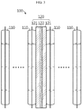
- FIG. 3 is a diagram showing a cell stack applied to the battery module according to an embodiment of the present disclosure, in which the temperature in the battery module is lower than a reference temperature
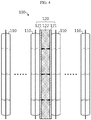
- FIG. 4 is a diagram showing the cell stack applied to the battery module according to an embodiment of the present disclosure, in which the temperature in the battery module is equal to or higher than the reference temperature.
- a battery module includes a cell stack 100 and a module case 200 for accommodating the cell stack 100.
- the cell stack 100 includes a plurality of battery cells 110 and at least one pad composite 120 interposed between neighboring battery cells 110.
- the battery cell 110 for example, a pouch-type battery cell may be applied. If the battery cell 110 is a pouch-type battery cell, as shown in FIG. 2 , the battery cell 110 is implemented to include an electrode assembly (not shown), a pouch case 111, an electrode lead 112 and a sealing tape 113.
- the electrode assembly has a form in which separators are interposed between positive electrode plates and negative electrode plates that are repeatedly stacked alternately, and separators are preferably positioned at both outermost sides for insulation, respectively.
- the positive electrode plate includes a positive electrode current collector and a positive electrode active material layer coated on one side of the positive electrode current collector, and a positive electrode uncoated region not coated with a positive electrode active material is formed at one side end of the positive electrode plate.
- the positive electrode uncoated region functions as a positive electrode tab.
- the negative electrode plate includes a negative electrode current collector and a negative electrode active material layer coated on one surface or both sides of the negative electrode current collector, and a negative electrode uncoated region not coated with a negative electrode active material is formed at one side end of the negative electrode plate.
- the negative electrode uncoated region functions as a negative electrode tab.
- the separator is interposed between the positive electrode plate and the negative electrode plate to prevent electrode plates having different polarities from directly contacting each other.
- the separator may made of a porous material so that ions may be moved using the electrolyte as a medium between the positive electrode plate and the negative electrode plate.
- the cell case 111 includes two regions, namely an accommodation portion 111a accommodating the electrode assembly and a sealing portion 111b extending in a circumferential direction of the accommodation portion 111a and thermally fused in a state where the electrode lead 112 is drawn out to seal the cell case 111.
- the cell case 111 is sealed by affixing and thermally fusing edge portions of an upper case and a lower case made of a multi-layered pouch film in which a resin layer, a metal layer and a resin layer are stacked in order.
- the pair of electrode leads 112 are connected to a positive electrode tab (not shown) and a negative electrode tab (not shown), respectively, and are drawn out of the cell case 111.
- the pair of electrode leads 112 are drawn in parallel to one side in a longitudinal direction of the battery cell 110 or are drawn to one side and the other side in the longitudinal direction of the battery cell 110, respectively. That is, the battery cell 110 applied to the present disclosure may be a one-directional drawing-type battery cell in which the positive electrode lead and the negative electrode lead are drawn in the same direction to each other or a two-directional drawing-type battery cell in which the positive electrode lead and the negative electrode lead are in opposite directions.
- the sealing tape 113 is attached to the circumference of the electrode lead 112, and is interposed between an inner surface of the sealing portion 111b of the pouch case 111 and the electrode lead 112.
- the sealing tape 113 prevents the sealing property of the sealing portion 111b from being weakened due to the drawing-out of the electrode lead 112.
- the pad composite 120 is interposed between neighboring battery cells 110, and may be provided just in single to minimize the increase in thickness of the cell stack 100. If the single pad composite 120 is provided as above, the pad composite 120 is preferably disposed at the center of the cell stack 100 in a stacking direction. This is to effectively block the propagation of thermal runaway between the neighboring battery cells 110.
- the pad composite 120 includes a pair of swelling absorption pads 121 and a heat shielding pad 122 interposed between the pair of swelling absorption pads 121.
- the swelling absorption pad 121 is compressed to absorb the swelling.
- the swelling absorption pad 121 may be made of a material with elasticity, and may include, for example, at least one of expanded polypropylene (EPP) and urethane.
- the swelling absorption pad 121 is damaged and shrunken. If the high temperature state is maintained over a certain time, the thickness gets closer to 0.
- the heat shielding pad 122 is interposed between the pair of swelling absorption pads 121 to minimize heat transfer between the battery cells 110 located at both sides with the pad composite 120 being interposed therebetween.
- the heat shielding pad 122 has a characteristic of expanding if the temperature inside the battery module abnormally rises to a temperature (about 100°C to 300°C) or above at which the swelling absorption pad 121 is damaged and shrunken.
- the heat shielding pad 122 may include, for example, at least one of epoxy-based resin, butyl-based resin, and vinyl chloride-based resin.
- the heat shielding pad 122 is expanded to fill the space formed by the damage of the swelling absorption pad 121. That is, the heat shielding pad 122 prevents that the swelling absorption pad 121 is damaged due to abnormal heating of the battery module to create an empty space between the neighboring battery cells 110, thereby preventing the neighboring battery cells 110 from getting closer and efficiently blocking heat transfer.
- the heat shielding pad 122 has an expansion rate of about 5 to 40 and is expanded only in the thickness direction. Therefore, if the internal temperature of the battery module rises to the reference temperature or above, the heat shielding pad 122 may be sufficiently expanded so that no empty space is generated between the neighboring battery cells 110.
- the heat shielding pad 122 may have very low thermal conductivity in the range of about 0.05 to 0.5 W/m-k, and thus may minimize heat transfer between the battery cells 110 located at both sides with the pad composite 120 being interposed therebetween.
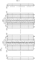
- FIG. 5 is a diagram showing a cell stack applied to a battery module according to another embodiment of the present disclosure.
- the battery module according to another embodiment of the present disclosure is different from the battery module according to the former embodiment of the present disclosure described above only in the number of the pad composite 120, and other features are substantially identical to those of the former embodiment.
- a battery module includes a plurality of pad composites 120.
- the pad composites 120 are respectively disposed between cell groups, each including a plurality of battery cells 110.
- the number of battery cells 110 included in one cell group may be determined in consideration of the number of battery cells 110 included in the battery module, the capacity of the battery cells 110, the thickness of the pad composite 120, or the like.
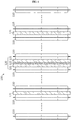
- FIG. 6 is a diagram showing a cell stack applied to a battery module according to still another embodiment of the present disclosure.
- the battery module according to still another embodiment of the present disclosure is different from the battery module according to the former embodiment of the present disclosure described above only in that the swelling absorption pad 121 is further applied in addition to the pad composite 120, and other features are substantially identical to those of the former embodiment.
- the battery module according to still another embodiment of the present disclosure further includes a plurality of swelling absorption pads 121 respectively disposed between cell groups, each including a plurality of battery cells 110, in addition to the pad composite 120 disposed at the center of the cell stack 100 in the thickness direction.
- the swelling absorption pads 121 are applied to various locations of the cell stack 100 as described above, the volume expansion caused by swelling of the battery cell 110 may be stably absorbed.
- the battery module according to still another embodiment of the present disclosure includes the pad composite 120 at the center of the cell stack 100, similar to the battery module according to the former embodiment of the present disclosure described above, even when abnormal heating occurs, it is possible to prevent or delay the propagation of thermal runaway, bordered on the center of the cell stack 100 in the thickness direction, thereby ensuring the safety of the battery module in use.
Landscapes
- Chemical & Material Sciences (AREA)
- Chemical Kinetics & Catalysis (AREA)
- Electrochemistry (AREA)
- General Chemical & Material Sciences (AREA)
- Engineering & Computer Science (AREA)
- Manufacturing & Machinery (AREA)
- Battery Mounting, Suspending (AREA)
- Secondary Cells (AREA)
Abstract
Description
- The present disclosure relates to a battery module including a pad composite having swelling absorption and heat shielding functions, a battery pack and a vehicle including the battery module, and more specifically, to a battery module including a pad composite having a swelling absorption pad compressed according to expansion of a battery cell by swelling and a heat shielding pad expanded when the swelling absorption pad is damaged due to a rise in an internal temperature of the battery module to fill the space occupied by the swelling absorption pad, and a battery pack and a vehicle including the battery module.
- The present application claims priority to
Korean Patent Application No. 10-2019-0024840 filed on March 4, 2019 - In general, a battery module includes a cooling system to prevent the life span of the battery module from being shortened rapidly due to temperature when used for a long time. The cooling system is designed in consideration of a heat generation amount and the like according to the environment in which the battery module is used.
- However, if some battery cells show abnormal heating due to failure while the battery module is being used, the temperature may continuously rise. In this case, if the temperature exceeds a critical temperature, thermal runaway may occur to cause a safety issue.
- That is, if the thermal runaway generated in some battery cells propagates to neighboring battery cells within a short time, the temperature of the battery module rises rapidly as a whole, which may lead to a rise in temperature of the entire battery pack including a plurality of battery modules and thus seriously damage property and human life. Therefore, in order to prevent rapid propagation of the thermal runaway phenomenon, it is necessary to apply a member for heat shielding between adjacent battery cells.
- In addition, a buffer member compressed according to expansion of the battery cell due to swelling to absorb the swelling is applied between adjacent battery cells. The buffer member may employ an EPP pad (an expanded polypropylene pad) or a urethane pad.
- The buffer pad made of this material has a certain level of elasticity in a normal use of the battery module to have a function of absorbing swelling by being compressed when the battery cell expands due to swelling. Also, the buffer pad may have a function of maintaining a gap between adjacent battery cells and delaying heat transfer between adjacent battery cells at abnormal heating.
- However, the buffer pad of this material may be easily damaged and contracted if a thermal runaway phenomenon occurs in some battery cells so that the temperature in the battery module exceeds a threshold value.
- If the buffer pad is damaged by heat and contracted as described above, the gap between adjacent battery cells is reduced with the buffer pad being interposed therebetween, and thus the thermal runaway phenomenon may be propagated faster between the adjacent battery cells.
- Therefore, there is also a need to develop a battery module having a structure capable of absorbing a volume expansion caused by swelling of the battery cell, maintaining the gap between adjacent battery cells constantly even if the temperature in the battery module rises above a threshold value due to abnormal heating generated in some battery cells, and delaying propagation of thermal runaway between adjacent battery cells.
- The present disclosure is designed to solve the problems of the related art, and therefore the present disclosure is directed to providing a battery module having a structure that may absorb a volume expansion caused by swelling of the battery cell, maintain the gap between adjacent battery cells constantly even if the temperature in the battery module rises above a threshold value due to abnormal heating generated in some battery cells, and delay propagation of thermal runaway between adjacent battery cells.
- However, the technical problem to be solved by the present disclosure is not limited to the above, and other objects not mentioned herein will be understood from the following description by those skilled in the art.
- In one aspect of the present disclosure, there is provided a battery module, comprising: a cell stack including a plurality of battery cells and at least one pad composite interposed between neighboring battery cells; and a module case configured to accommodate the cell stack, wherein the pad composite includes: a pair of swelling absorption pads compressed according to a volume expansion of the battery cell caused by swelling; and a heat shielding pad interposed between the pair of swelling absorption pads to block heat transfer between the neighboring battery cells and configured to expand at a preset reference temperature or above.
- The swelling absorption pad may be shrunken at the reference temperature or above to reduce a thickness.
- The heat shielding pad may be expanded at the reference temperature or above to fill the space created by shrinkage of the swelling absorption pad.
- The heat shielding pad may have an expansion rate of 5 to 40 in a thickness direction at the reference temperature or above.
- The battery cell may be a pouch-type battery cell.
- The pad composite may be provided in single, and the single pad composite may be disposed at a center of the cell stack in a stacking direction.
- The battery module may further comprise a plurality of swelling absorption pads respectively disposed between cell groups, each including a plurality of battery cells.
- The pad composite may be provided in plural, and the plurality of pad composites may be respectively disposed between cell groups, each including a plurality of battery cells.
- The swelling absorption pad may include at least one of expanded polypropylene (EPP) and urethane.
- The heat shielding pad may include at least one of epoxy-based resin, butyl-based resin, and vinyl chloride-based resin.
- In another aspect of the present disclosure, there are also provided a battery pack and a vehicle, which comprises the battery module according to the present disclosure.
- According to an embodiment of the present disclosure, it is possible to provide a battery module having a structure capable of absorbing a volume expansion caused by swelling of the battery cell, maintaining the gap between adjacent battery cells constantly even if the temperature in the battery module rises above a threshold value due to abnormal heating generated in some battery cells, and delaying propagation of thermal runaway between adjacent battery cells.
- The accompanying drawings illustrate a preferred embodiment of the present disclosure and together with the foregoing disclosure, serve to provide further understanding of the technical features of the present disclosure, and thus, the present disclosure is not construed as being limited to the drawing.
-
FIG. 1 is a perspective view showing a battery module according to an embodiment of the present disclosure. -
FIG. 2 is a diagram showing a battery cell applied to the battery module according to an embodiment of the present disclosure. -
FIG. 3 is a diagram showing a cell stack applied to the battery module according to an embodiment of the present disclosure, in which the temperature in the battery module is lower than a reference temperature. -
FIG. 4 is a diagram showing the cell stack applied to the battery module according to an embodiment of the present disclosure, in which the temperature in the battery module is equal to or higher than the reference temperature. -
FIG. 5 is a diagram showing a cell stack applied to a battery module according to another embodiment of the present disclosure. -
FIG. 6 is a diagram showing a cell stack applied to a battery module according to still another embodiment of the present disclosure. - Hereinafter, preferred embodiments of the present disclosure will be described in detail with reference to the accompanying drawings. Prior to the description, it should be understood that the terms used in the specification and the appended claims should not be construed as limited to general and dictionary meanings, but interpreted based on the meanings and concepts corresponding to technical aspects of the present disclosure on the basis of the principle that the inventor is allowed to define terms appropriately for the best explanation. Therefore, the description proposed herein is just a preferable example for the purpose of illustrations only, not intended to limit the scope of the disclosure, so it should be understood that other equivalents and modifications could be made thereto without departing from the scope of the disclosure.
- First, a battery module according to an embodiment of the present disclosure will be described with reference to
FIGS. 1 to 4 . -
FIG. 1 is a perspective view showing a battery module according to an embodiment of the present disclosure, andFIG. 2 is a diagram showing a battery cell applied to the battery module according to an embodiment of the present disclosure. Also,FIG. 3 is a diagram showing a cell stack applied to the battery module according to an embodiment of the present disclosure, in which the temperature in the battery module is lower than a reference temperature, andFIG. 4 is a diagram showing the cell stack applied to the battery module according to an embodiment of the present disclosure, in which the temperature in the battery module is equal to or higher than the reference temperature. - Referring to
FIGS. 1 to 4 , a battery module according to an embodiment of the present disclosure includes acell stack 100 and amodule case 200 for accommodating thecell stack 100. Thecell stack 100 includes a plurality ofbattery cells 110 and at least onepad composite 120 interposed between neighboringbattery cells 110. - As the
battery cell 110, for example, a pouch-type battery cell may be applied. If thebattery cell 110 is a pouch-type battery cell, as shown inFIG. 2 , thebattery cell 110 is implemented to include an electrode assembly (not shown), apouch case 111, anelectrode lead 112 and asealing tape 113. - Although not shown in the drawings, the electrode assembly has a form in which separators are interposed between positive electrode plates and negative electrode plates that are repeatedly stacked alternately, and separators are preferably positioned at both outermost sides for insulation, respectively.
- The positive electrode plate includes a positive electrode current collector and a positive electrode active material layer coated on one side of the positive electrode current collector, and a positive electrode uncoated region not coated with a positive electrode active material is formed at one side end of the positive electrode plate. The positive electrode uncoated region functions as a positive electrode tab.
- The negative electrode plate includes a negative electrode current collector and a negative electrode active material layer coated on one surface or both sides of the negative electrode current collector, and a negative electrode uncoated region not coated with a negative electrode active material is formed at one side end of the negative electrode plate. The negative electrode uncoated region functions as a negative electrode tab.
- In addition, the separator is interposed between the positive electrode plate and the negative electrode plate to prevent electrode plates having different polarities from directly contacting each other. The separator may made of a porous material so that ions may be moved using the electrolyte as a medium between the positive electrode plate and the negative electrode plate.
- The
cell case 111 includes two regions, namely anaccommodation portion 111a accommodating the electrode assembly and asealing portion 111b extending in a circumferential direction of theaccommodation portion 111a and thermally fused in a state where theelectrode lead 112 is drawn out to seal thecell case 111. - Although not shown in the figures, the
cell case 111 is sealed by affixing and thermally fusing edge portions of an upper case and a lower case made of a multi-layered pouch film in which a resin layer, a metal layer and a resin layer are stacked in order. - The pair of electrode leads 112 are connected to a positive electrode tab (not shown) and a negative electrode tab (not shown), respectively, and are drawn out of the
cell case 111. The pair of electrode leads 112 are drawn in parallel to one side in a longitudinal direction of thebattery cell 110 or are drawn to one side and the other side in the longitudinal direction of thebattery cell 110, respectively. That is, thebattery cell 110 applied to the present disclosure may be a one-directional drawing-type battery cell in which the positive electrode lead and the negative electrode lead are drawn in the same direction to each other or a two-directional drawing-type battery cell in which the positive electrode lead and the negative electrode lead are in opposite directions. - The sealing
tape 113 is attached to the circumference of theelectrode lead 112, and is interposed between an inner surface of the sealingportion 111b of thepouch case 111 and theelectrode lead 112. The sealingtape 113 prevents the sealing property of the sealingportion 111b from being weakened due to the drawing-out of theelectrode lead 112. - The
pad composite 120 is interposed between neighboringbattery cells 110, and may be provided just in single to minimize the increase in thickness of thecell stack 100. If thesingle pad composite 120 is provided as above, thepad composite 120 is preferably disposed at the center of thecell stack 100 in a stacking direction. This is to effectively block the propagation of thermal runaway between the neighboringbattery cells 110. - The
pad composite 120 includes a pair of swellingabsorption pads 121 and aheat shielding pad 122 interposed between the pair of swellingabsorption pads 121. - If swelling occurs in the
battery cells 110 due to repeated charging and discharging of the battery module and thus thebattery cells 110 are expanded convexly along the stacking direction, the swellingabsorption pad 121 is compressed to absorb the swelling. In consideration of this function, the swellingabsorption pad 121 may be made of a material with elasticity, and may include, for example, at least one of expanded polypropylene (EPP) and urethane. - If the temperature inside the battery module becomes high temperature of about 100°C to 300°C due to abnormal heating of the battery module, the swelling
absorption pad 121 is damaged and shrunken. If the high temperature state is maintained over a certain time, the thickness gets closer to 0. - The
heat shielding pad 122 is interposed between the pair of swellingabsorption pads 121 to minimize heat transfer between thebattery cells 110 located at both sides with thepad composite 120 being interposed therebetween. In addition, theheat shielding pad 122 has a characteristic of expanding if the temperature inside the battery module abnormally rises to a temperature (about 100°C to 300°C) or above at which theswelling absorption pad 121 is damaged and shrunken. - For the operating characteristics according to the temperature, the
heat shielding pad 122 may include, for example, at least one of epoxy-based resin, butyl-based resin, and vinyl chloride-based resin. - If the internal temperature of the battery module rises to a reference temperature (about 100°C to 300°C) due to an abnormal heating phenomenon of the battery module, the
heat shielding pad 122 is expanded to fill the space formed by the damage of the swellingabsorption pad 121. That is, theheat shielding pad 122 prevents that the swellingabsorption pad 121 is damaged due to abnormal heating of the battery module to create an empty space between the neighboringbattery cells 110, thereby preventing the neighboringbattery cells 110 from getting closer and efficiently blocking heat transfer. - The
heat shielding pad 122 has an expansion rate of about 5 to 40 and is expanded only in the thickness direction. Therefore, if the internal temperature of the battery module rises to the reference temperature or above, theheat shielding pad 122 may be sufficiently expanded so that no empty space is generated between the neighboringbattery cells 110. - In addition, the
heat shielding pad 122 may have very low thermal conductivity in the range of about 0.05 to 0.5 W/m-k, and thus may minimize heat transfer between thebattery cells 110 located at both sides with thepad composite 120 being interposed therebetween. - Next, a battery module according to another embodiment of the present disclosure will be described with reference to
FIG. 5 . -
FIG. 5 is a diagram showing a cell stack applied to a battery module according to another embodiment of the present disclosure. - The battery module according to another embodiment of the present disclosure is different from the battery module according to the former embodiment of the present disclosure described above only in the number of the
pad composite 120, and other features are substantially identical to those of the former embodiment. - Therefore, in describing the battery module according to another embodiment of the present disclosure, locations at which the plurality of
pad composites 120 are provided will be intensively described, and other features identical to those of the former embodiment will not be described in detail. - Referring to
FIG. 5 , a battery module according to another embodiment of the present disclosure includes a plurality ofpad composites 120. Thepad composites 120 are respectively disposed between cell groups, each including a plurality ofbattery cells 110. The number ofbattery cells 110 included in one cell group may be determined in consideration of the number ofbattery cells 110 included in the battery module, the capacity of thebattery cells 110, the thickness of thepad composite 120, or the like. - Next, a battery module according to still another embodiment of the present disclosure will be described with reference to
FIG. 6 . -
FIG. 6 is a diagram showing a cell stack applied to a battery module according to still another embodiment of the present disclosure. - The battery module according to still another embodiment of the present disclosure is different from the battery module according to the former embodiment of the present disclosure described above only in that the swelling
absorption pad 121 is further applied in addition to thepad composite 120, and other features are substantially identical to those of the former embodiment. - Therefore, in describing the battery module according to another embodiment of the present disclosure, a location at which the
swelling absorption pad 121 is additionally applied will be intensively described, and other features identical to those of the former embodiment will not be described in detail. - The battery module according to still another embodiment of the present disclosure further includes a plurality of swelling
absorption pads 121 respectively disposed between cell groups, each including a plurality ofbattery cells 110, in addition to thepad composite 120 disposed at the center of thecell stack 100 in the thickness direction. - If the swelling
absorption pads 121 are applied to various locations of thecell stack 100 as described above, the volume expansion caused by swelling of thebattery cell 110 may be stably absorbed. In addition, since the battery module according to still another embodiment of the present disclosure includes thepad composite 120 at the center of thecell stack 100, similar to the battery module according to the former embodiment of the present disclosure described above, even when abnormal heating occurs, it is possible to prevent or delay the propagation of thermal runaway, bordered on the center of thecell stack 100 in the thickness direction, thereby ensuring the safety of the battery module in use. - The present disclosure has been described in detail. However, it should be understood that the detailed description and specific examples, while indicating preferred embodiments of the disclosure, are given by way of illustration only, since various changes and modifications within the scope of the disclosure will become apparent to those skilled in the art from this detailed description.
Claims (12)
- A battery module, comprising:a cell stack including a plurality of battery cells and at least one pad composite interposed between neighboring battery cells; anda module case configured to accommodate the cell stack,wherein the pad composite includes:a pair of swelling absorption pads compressed according to a volume expansion of the battery cell caused by swelling; anda heat shielding pad interposed between the pair of swelling absorption pads to block heat transfer between the neighboring battery cells and configured to expand at a preset reference temperature or above.
- The battery module according to claim 1,
wherein the swelling absorption pad is shrunken at the reference temperature or above to reduce a thickness. - The battery module according to claim 2,
wherein the heat shielding pad is expanded at the reference temperature or above to fill the space created by shrinkage of the swelling absorption pad. - The battery module according to claim 3,
wherein the heat shielding pad has an expansion rate of 5 to 40 in a thickness direction at the reference temperature or above. - The battery module according to claim 1,
wherein the battery cell is a pouch-type battery cell. - The battery module according to claim 1,
wherein the pad composite is provided in single, and the single pad composite is disposed at a center of the cell stack in a stacking direction. - The battery module according to claim 6, further comprising:
a plurality of swelling absorption pads respectively disposed between cell groups, each including a plurality of battery cells. - The battery module according to claim 1,
wherein the pad composite is provided in plural, and the plurality of pad composites are respectively disposed between cell groups, each including a plurality of battery cells. - The battery module according to claim 1,
wherein the swelling absorption pad includes at least one of expanded polypropylene (EPP) and urethane. - The battery module according to claim 1,
wherein the heat shielding pad includes at least one of epoxy-based resin, butyl-based resin, and vinyl chloride-based resin. - A battery pack, comprising the battery module according to any one of claims 1 to 10.
- A vehicle, comprising the battery module according to any one of claims 1 to 10.
Applications Claiming Priority (2)
| Application Number | Priority Date | Filing Date | Title |
|---|---|---|---|
| KR1020190024840A KR102762534B1 (en) | 2019-03-04 | 2019-03-04 | A battery module comprising a pad composite having swelling absorption and heat shielding function, a battery pack and a vehicle comprising the same |
| PCT/KR2020/003082 WO2020180114A1 (en) | 2019-03-04 | 2020-03-04 | Battery module having pad composite having swelling absorption and heat shielding function, battery pack comprising same and vehicle |
Publications (3)
| Publication Number | Publication Date |
|---|---|
| EP3893291A1 true EP3893291A1 (en) | 2021-10-13 |
| EP3893291A4 EP3893291A4 (en) | 2022-02-16 |
| EP3893291B1 EP3893291B1 (en) | 2024-05-01 |
Family
ID=72337963
Family Applications (1)
| Application Number | Title | Priority Date | Filing Date |
|---|---|---|---|
| EP20767165.2A Active EP3893291B1 (en) | 2019-03-04 | 2020-03-04 | Battery module having pad composite having swelling absorption and heat shielding function, battery pack comprising same and vehicle |
Country Status (9)
| Country | Link |
|---|---|
| US (5) | US12676352B2 (en) |
| EP (1) | EP3893291B1 (en) |
| JP (3) | JP7297062B2 (en) |
| KR (2) | KR102762534B1 (en) |
| CN (1) | CN112689926A (en) |
| ES (1) | ES2985179T3 (en) |
| HU (1) | HUE067482T2 (en) |
| PL (1) | PL3893291T3 (en) |
| WO (1) | WO2020180114A1 (en) |
Cited By (10)
| Publication number | Priority date | Publication date | Assignee | Title |
|---|---|---|---|---|
| EP4095988A1 (en) * | 2021-05-27 | 2022-11-30 | CALB Co., Ltd. | Battery apparatus |
| DE102021213889A1 (en) | 2021-12-07 | 2023-06-07 | Volkswagen Aktiengesellschaft | Absorption cushion for arrangement between battery cells of a battery system and arrangement of such absorption cushions in a battery system |
| EP4084199A4 (en) * | 2020-10-05 | 2023-11-22 | LG Energy Solution, Ltd. | BATTERY MODULE INCLUDING A BUFFER PAD TO PREVENT BATTERY CELL DAMAGE, AND BATTERY PACK INCLUDING SAME |
| DE102022128911A1 (en) | 2022-11-02 | 2024-05-02 | Dr. Ing. H.C. F. Porsche Aktiengesellschaft | Compression pad with shape memory function and manufacturing process therefor |
| SE2251487A1 (en) * | 2022-12-19 | 2024-06-20 | Scania Cv Ab | Battery Module, Battery Pack, Vehicle, Temperature Control Arrangement, and Method of Controlling Temperature of Battery Cells |
| AT527616A1 (en) * | 2023-10-04 | 2025-04-15 | Miba Emobility Gmbh | Storage device for electrical energy |
| EP4432436A4 (en) * | 2021-11-11 | 2025-10-29 | Samsung Sdi Co Ltd | RECHARGEABLE BATTERY MODULE |
| SE547930C2 (en) * | 2022-12-19 | 2025-12-23 | Scania Cv Ab | Battery Module, Battery Pack, Vehicle, Temperature Control Arrangement, and Method of Controlling Temperature of Battery Cells |
| EP4550531A4 (en) * | 2022-12-28 | 2026-01-21 | Lg Energy Solution Ltd | BATTERY ARRANGEMENT AND BATTERY PACK AS WELL AS VEHICLE WITH IT |
| GB2642987A (en) * | 2024-07-26 | 2026-02-04 | Mercedes Benz Group Ag | A battery module for an electrical energy storage device of a motor vehicle, an electrical energy storage device and a method |
Families Citing this family (45)
| Publication number | Priority date | Publication date | Assignee | Title |
|---|---|---|---|---|
| CN210006793U (en) * | 2019-07-04 | 2020-01-31 | 江苏时代新能源科技有限公司 | battery module |
| KR102917974B1 (en) | 2020-10-20 | 2026-01-23 | 주식회사 엘지에너지솔루션 | Battery module and battery pack including the same and vehicle including the same |
| KR102895840B1 (en) | 2021-01-08 | 2025-12-03 | 주식회사 엘지에너지솔루션 | Battery module and battery pack including the same and vehicle including the same |
| KR102884911B1 (en) * | 2021-01-22 | 2025-11-13 | 주식회사 엘지에너지솔루션 | A Battery Module Equipped With A Fire Spread Prevention Structure And A Battery Pack Including It |
| KR20220114888A (en) | 2021-02-09 | 2022-08-17 | 주식회사 엘지에너지솔루션 | Battery module and battery pack including the same |
| WO2022182016A1 (en) * | 2021-02-24 | 2022-09-01 | 주식회사 엘지에너지솔루션 | Battery module and battery pack including same |
| KR102332128B1 (en) | 2021-04-01 | 2021-12-01 | 주식회사 엘투와이 | Silicone sponge pad having preventing thermal runaway function and, battery pack with the same |
| CN113224446B (en) * | 2021-04-14 | 2025-01-28 | 浙江零跑科技股份有限公司 | Battery modules and battery packs |
| KR102713991B1 (en) * | 2021-05-20 | 2024-10-07 | 주식회사 엘지에너지솔루션 | Battery module with improved safety |
| PL4239768T3 (en) * | 2021-05-20 | 2025-11-03 | Lg Energy Solution, Ltd. | Battery module with improved safety |
| KR20220170175A (en) | 2021-06-22 | 2022-12-29 | 에스케이온 주식회사 | Battery pack and battery system using thereof |
| KR102841613B1 (en) * | 2021-08-17 | 2025-08-01 | 에스케이온 주식회사 | Module pack comprising a thermal barrier and pack comprising the module |
| DE102021121397A1 (en) * | 2021-08-18 | 2023-02-23 | Dr. Ing. H.C. F. Porsche Aktiengesellschaft | battery arrangement |
| KR102377172B1 (en) * | 2021-10-07 | 2022-03-22 | 주식회사 서연이화 | Battery system and method with swelling detection and corresponding to swelling |
| KR20230064784A (en) | 2021-11-04 | 2023-05-11 | 주식회사 엘지에너지솔루션 | Battery module |
| KR102425374B1 (en) | 2021-11-08 | 2022-07-27 | 주식회사 엘투와이 | Silicone pad for preventing thermal runaway function having thermal diffusion sheet, and battery pack with the same |
| DE102021132072A1 (en) * | 2021-12-06 | 2023-06-07 | Carl Freudenberg Kg | energy storage system |
| EP4456285A4 (en) * | 2021-12-24 | 2025-06-11 | LG Energy Solution, Ltd. | LOGIC CELL, SECONDARY BATTERY MODULE AND CORRESPONDING SECONDARY BATTERY PACK |
| KR102577201B1 (en) | 2022-01-14 | 2023-09-14 | 에스케이온 주식회사 | Battery module and battery pack |
| CN217182283U (en) * | 2022-01-20 | 2022-08-12 | 宁德时代新能源科技股份有限公司 | Heat insulation element, battery and electric device |
| JP7758853B2 (en) * | 2022-03-31 | 2025-10-22 | エルジー エナジー ソリューション リミテッド | Battery module with enhanced safety |
| KR102658211B1 (en) * | 2022-03-31 | 2024-04-18 | 주식회사 엘지에너지솔루션 | Battery module with reinforced safety |
| WO2023195713A1 (en) * | 2022-04-07 | 2023-10-12 | 주식회사 엘지에너지솔루션 | Secondary battery module and secondary battery pack comprising same |
| US20230402683A1 (en) * | 2022-05-17 | 2023-12-14 | Ford Global Technologies, Llc | Battery system for a hybrid or electric vehicle |
| CN220627729U (en) | 2022-06-27 | 2024-03-19 | 米沃奇电动工具公司 | Fuses and devices including conductive paths for the passage of electric current |
| CN118056324A (en) | 2022-08-10 | 2024-05-17 | 株式会社 Lg新能源 | Battery pack and vehicle including the battery pack |
| KR20240028583A (en) * | 2022-08-24 | 2024-03-05 | 주식회사 엘지에너지솔루션 | Battery module and battery pack including the same |
| KR20240047080A (en) * | 2022-10-04 | 2024-04-12 | 주식회사 엘지에너지솔루션 | Battery cell wherein heat propagation is prevented |
| DE102022126590A1 (en) | 2022-10-12 | 2024-04-18 | Parker Hannifin EMEA S.à.r.l | Insert element for a battery module and battery module |
| WO2024087102A1 (en) * | 2022-10-27 | 2024-05-02 | 宁德时代新能源科技股份有限公司 | Battery and electric device |
| CN118575344A (en) * | 2022-10-27 | 2024-08-30 | 宁德时代新能源科技股份有限公司 | Battery and electricity utilization device |
| JP7495468B2 (en) * | 2022-11-11 | 2024-06-04 | イビデン株式会社 | Heat transfer suppression sheet and battery pack |
| CN119452513A (en) * | 2022-12-05 | 2025-02-14 | 株式会社Lg新能源 | Battery module, battery pack and vehicle including the battery module |
| KR20240100138A (en) * | 2022-12-22 | 2024-07-01 | 주식회사 엘지에너지솔루션 | Battery module with improved venting structure |
| JP7839297B2 (en) * | 2022-12-23 | 2026-04-01 | エルジー エナジー ソリューション リミテッド | Battery pack, and automobiles including said battery pack |
| JP7623414B2 (en) * | 2023-03-10 | 2025-01-28 | 住友理工株式会社 | Cell housing material |
| KR102872933B1 (en) | 2023-03-21 | 2025-10-17 | 주식회사 엘투와이 | Silicone form pad having preventing thermal runaway function and, battery pack with the same |
| KR102659474B1 (en) | 2023-03-28 | 2024-04-22 | 주식회사 에이치티씨 | Battery module having heat dissipation and insulation function and battery pack having the same |
| CN119009311A (en) * | 2023-05-16 | 2024-11-22 | 宁德时代新能源科技股份有限公司 | Battery cell, battery and electricity utilization device |
| WO2024238717A1 (en) * | 2023-05-17 | 2024-11-21 | Enphase Energy, Inc. | Battery systems with thermal fuse for enhanced thermal safety |
| KR20250035943A (en) * | 2023-09-06 | 2025-03-13 | 주식회사 엘지에너지솔루션 | Battery module and battery pack including the same and vehicle including the same |
| EP4712225A1 (en) * | 2023-11-16 | 2026-03-18 | LG Energy Solution, Ltd. | Secondary battery and cell stack comprising same |
| KR102925813B1 (en) * | 2023-12-22 | 2026-02-10 | 주식회사 엘지에너지솔루션 | Compression pad, battery cell stack and battery module including the same |
| WO2025192891A1 (en) * | 2024-03-13 | 2025-09-18 | 주식회사 엘지에너지솔루션 | Battery assembly and battery pack including same |
| KR20250178847A (en) * | 2024-06-20 | 2025-12-29 | 주식회사 엘지에너지솔루션 | Battery pack including the same |
Family Cites Families (31)
| Publication number | Priority date | Publication date | Assignee | Title |
|---|---|---|---|---|
| US3770565A (en) | 1972-01-05 | 1973-11-06 | Us Navy | Plastic mounting of epitaxially grown iv-vi compound semiconducting films |
| US20170068291A1 (en) * | 2004-07-26 | 2017-03-09 | Yi-Chuan Cheng | Cellular with a Heat Pumping Device |
| US20060243315A1 (en) | 2005-04-29 | 2006-11-02 | Chrysler Gregory M | Gap-filling in electronic assemblies including a TEC structure |
| MX2008016314A (en) | 2006-06-30 | 2009-02-25 | Toray Industries | Thermoplastic resin composition and molded article thereof. |
| US20080292950A1 (en) | 2007-05-24 | 2008-11-27 | Sanyo Electric Co., Ltd. | Battery module |
| JP5449695B2 (en) | 2007-05-24 | 2014-03-19 | 三洋電機株式会社 | Assembled battery |
| KR101029837B1 (en) | 2009-01-06 | 2011-04-15 | 주식회사 엘지화학 | Novel battery module and medium and large battery packs comprising the same |
| EP2555276A1 (en) | 2010-03-30 | 2013-02-06 | Panasonic Corporation | Battery pack |
| JP5889665B2 (en) * | 2012-02-14 | 2016-03-22 | シャープ株式会社 | Toner for electrostatic charge development, image forming apparatus using the same, and image forming method |
| KR101441207B1 (en) | 2012-12-27 | 2014-09-17 | 에이치엘그린파워 주식회사 | Current Interrupt Device using a thermal expansion pad |
| JP2014183013A (en) | 2013-03-21 | 2014-09-29 | Sumitomo Electric Ind Ltd | Battery pack |
| US9748548B2 (en) | 2013-07-30 | 2017-08-29 | Johnson Controls Technology Company | Pouch frame with integral circuitry for battery module |
| KR20160069807A (en) | 2014-12-09 | 2016-06-17 | 삼성에스디아이 주식회사 | Battery module |
| KR101745081B1 (en) | 2015-04-28 | 2017-06-08 | 현대자동차주식회사 | Battery Cell Supporter Assembly Integrated Cooling Structure Battery Module and Battery Module thereby |
| US10665913B2 (en) | 2015-05-12 | 2020-05-26 | GM Global Technology Operations LLC | Thermal propagation mitigation for HV battery modules |
| DE102015007408A1 (en) | 2015-06-10 | 2016-12-15 | Daimler Ag | Battery with at least one heat insulation in the thickness direction increasing thermal insulation element |
| KR102058194B1 (en) | 2015-09-07 | 2019-12-20 | 주식회사 엘지화학 | battery module |
| KR102024326B1 (en) | 2015-10-14 | 2019-09-23 | 주식회사 엘지화학 | Battery module and battery pack comprising the smae |
| KR102010012B1 (en) | 2015-11-26 | 2019-08-12 | 주식회사 엘지화학 | Battery pack comprising fire extinguishing apparatus and controlling method using the same |
| EP3349268B1 (en) | 2016-03-03 | 2019-12-25 | LG Chem, Ltd. | Cell assembly having cushion member |
| CN107437631A (en) * | 2016-05-26 | 2017-12-05 | 宁德时代新能源科技股份有限公司 | battery module |
| KR102256604B1 (en) * | 2016-05-31 | 2021-05-26 | 주식회사 엘지에너지솔루션 | Battery module, battery pack comprising the battery module and vehicle comprising the battery pack |
| WO2018062172A1 (en) | 2016-09-30 | 2018-04-05 | 積水化学工業株式会社 | Thermally conductive, thermally expandable resin composition, thermally conductive, thermally expandable molded body, battery module, and battery pack |
| CN106365306A (en) | 2016-11-03 | 2017-02-01 | 成都美富特膜科技有限公司 | Membrane component used for water treatment |
| CN206163663U (en) | 2016-11-25 | 2017-05-10 | 北京新能源汽车股份有限公司 | Automobile battery structure and automobile |
| JP2018116805A (en) | 2017-01-17 | 2018-07-26 | 積水化学工業株式会社 | Secondary battery module |
| KR102335202B1 (en) | 2017-02-20 | 2021-12-03 | 주식회사 엘지에너지솔루션 | Secondary Battery with improved Stability having Heat Expandable layer and Method thereof |
| JP6885791B2 (en) * | 2017-06-05 | 2021-06-16 | 積水化学工業株式会社 | Thermal runaway prevention sheet |
| KR102341404B1 (en) | 2017-06-21 | 2021-12-20 | 삼성에스디아이 주식회사 | Battery module |
| KR102461577B1 (en) | 2017-07-17 | 2022-11-01 | 삼성에스디아이 주식회사 | Secondary Battery Module |
| US10319669B2 (en) | 2017-08-31 | 2019-06-11 | Ixys, Llc | Packaged fast inverse diode component for PFC applications |
-
2019
- 2019-03-04 KR KR1020190024840A patent/KR102762534B1/en active Active
-
2020
- 2020-03-04 ES ES20767165T patent/ES2985179T3/en active Active
- 2020-03-04 PL PL20767165.2T patent/PL3893291T3/en unknown
- 2020-03-04 HU HUE20767165A patent/HUE067482T2/en unknown
- 2020-03-04 EP EP20767165.2A patent/EP3893291B1/en active Active
- 2020-03-04 JP JP2021519835A patent/JP7297062B2/en active Active
- 2020-03-04 WO PCT/KR2020/003082 patent/WO2020180114A1/en not_active Ceased
- 2020-03-04 US US17/279,903 patent/US12676352B2/en active Active
- 2020-03-04 CN CN202080005097.9A patent/CN112689926A/en active Pending
-
2023
- 2023-05-10 JP JP2023078100A patent/JP7662703B2/en active Active
- 2023-10-13 US US18/486,673 patent/US20240039073A1/en active Pending
- 2023-10-17 KR KR1020230138964A patent/KR102713269B1/en active Active
-
2024
- 2024-02-09 US US18/437,778 patent/US20240186608A1/en active Pending
- 2024-02-09 US US18/437,848 patent/US20240186609A1/en active Pending
- 2024-02-09 US US18/438,353 patent/US20240186610A1/en not_active Abandoned
-
2025
- 2025-04-02 JP JP2025061275A patent/JP7885395B2/en active Active
Cited By (14)
| Publication number | Priority date | Publication date | Assignee | Title |
|---|---|---|---|---|
| EP4084199A4 (en) * | 2020-10-05 | 2023-11-22 | LG Energy Solution, Ltd. | BATTERY MODULE INCLUDING A BUFFER PAD TO PREVENT BATTERY CELL DAMAGE, AND BATTERY PACK INCLUDING SAME |
| EP4095988A1 (en) * | 2021-05-27 | 2022-11-30 | CALB Co., Ltd. | Battery apparatus |
| EP4432436A4 (en) * | 2021-11-11 | 2025-10-29 | Samsung Sdi Co Ltd | RECHARGEABLE BATTERY MODULE |
| DE102021213889A1 (en) | 2021-12-07 | 2023-06-07 | Volkswagen Aktiengesellschaft | Absorption cushion for arrangement between battery cells of a battery system and arrangement of such absorption cushions in a battery system |
| DE102022128911A1 (en) | 2022-11-02 | 2024-05-02 | Dr. Ing. H.C. F. Porsche Aktiengesellschaft | Compression pad with shape memory function and manufacturing process therefor |
| EP4366059A1 (en) | 2022-11-02 | 2024-05-08 | Dr. Ing. h.c. F. Porsche Aktiengesellschaft | Compression pad having shape memory function and manufacturing method thereof |
| WO2024136733A1 (en) * | 2022-12-19 | 2024-06-27 | Scania Cv Ab | Battery module, battery pack, vehicle, temperature control arrangement, and method of controlling temperature of battery cells |
| SE547267C2 (en) * | 2022-12-19 | 2025-06-17 | Scania Cv Ab | Battery Module, Battery Pack, Vehicle, Temperature Control Arrangement, and Method of Controlling Temperature of Battery Cells |
| SE2251487A1 (en) * | 2022-12-19 | 2024-06-20 | Scania Cv Ab | Battery Module, Battery Pack, Vehicle, Temperature Control Arrangement, and Method of Controlling Temperature of Battery Cells |
| SE547930C2 (en) * | 2022-12-19 | 2025-12-23 | Scania Cv Ab | Battery Module, Battery Pack, Vehicle, Temperature Control Arrangement, and Method of Controlling Temperature of Battery Cells |
| EP4550531A4 (en) * | 2022-12-28 | 2026-01-21 | Lg Energy Solution Ltd | BATTERY ARRANGEMENT AND BATTERY PACK AS WELL AS VEHICLE WITH IT |
| AT527616A1 (en) * | 2023-10-04 | 2025-04-15 | Miba Emobility Gmbh | Storage device for electrical energy |
| AT527616B1 (en) * | 2023-10-04 | 2025-06-15 | Miba Emobility Gmbh | Storage device for electrical energy |
| GB2642987A (en) * | 2024-07-26 | 2026-02-04 | Mercedes Benz Group Ag | A battery module for an electrical energy storage device of a motor vehicle, an electrical energy storage device and a method |
Also Published As
| Publication number | Publication date |
|---|---|
| US12676352B2 (en) | 2026-07-07 |
| US20220037714A1 (en) | 2022-02-03 |
| US20240186609A1 (en) | 2024-06-06 |
| US20240186608A1 (en) | 2024-06-06 |
| WO2020180114A1 (en) | 2020-09-10 |
| HUE067482T2 (en) | 2024-10-28 |
| JP7885395B2 (en) | 2026-07-06 |
| KR102762534B1 (en) | 2025-02-03 |
| JP2025092708A (en) | 2025-06-19 |
| KR20200106378A (en) | 2020-09-14 |
| CN112689926A (en) | 2021-04-20 |
| KR102713269B1 (en) | 2024-10-02 |
| JP7297062B2 (en) | 2023-06-23 |
| KR20230150242A (en) | 2023-10-30 |
| JP2022506014A (en) | 2022-01-17 |
| PL3893291T3 (en) | 2024-07-08 |
| JP2023090943A (en) | 2023-06-29 |
| US20240186610A1 (en) | 2024-06-06 |
| ES2985179T3 (en) | 2024-11-04 |
| EP3893291A4 (en) | 2022-02-16 |
| EP3893291B1 (en) | 2024-05-01 |
| US20240039073A1 (en) | 2024-02-01 |
| JP7662703B2 (en) | 2025-04-15 |
Similar Documents
| Publication | Publication Date | Title |
|---|---|---|
| US20240186610A1 (en) | Battery apparatus | |
| KR102949547B1 (en) | A battery pack with thermal propagation prevention structure between battery modules | |
| KR102480735B1 (en) | Battery module and battery pack including the same | |
| JP7558617B2 (en) | Battery module and battery pack including same | |
| EP4231423B1 (en) | Battery module including compression pad having improved insulation and assembly, battery pack and vehicle including the same | |
| EP3686986B1 (en) | Battery module and battery pack including the same | |
| JP7625320B2 (en) | Battery module including expansion buffer unit | |
| US20230318132A1 (en) | Battery module with reinforced safety | |
| KR102647832B1 (en) | Battery module and battery pack including the same | |
| JP7395231B2 (en) | Battery module and battery pack containing it | |
| CA3221615A1 (en) | Battery cell, battery module, battery pack and vehicle including the same | |
| JP7674040B2 (en) | Battery module and manufacturing method thereof | |
| KR102767817B1 (en) | A battery pack comprising a contact-type cooling plate and device with it | |
| KR20240166667A (en) | Battery Pack | |
| KR102910521B1 (en) | Battery module and battery pack including the same | |
| JP2023551225A (en) | Battery module and battery pack containing it | |
| EP4379908B1 (en) | Battery module with reinforced safety | |
| KR102910002B1 (en) | Battery module | |
| JP2025174157A (en) | Battery module and spacer used in the battery module | |
| JP2026503945A (en) | Devices containing battery packs |
Legal Events
| Date | Code | Title | Description |
|---|---|---|---|
| STAA | Information on the status of an ep patent application or granted ep patent |
Free format text: STATUS: THE INTERNATIONAL PUBLICATION HAS BEEN MADE |
|
| PUAI | Public reference made under article 153(3) epc to a published international application that has entered the european phase |
Free format text: ORIGINAL CODE: 0009012 |
|
| STAA | Information on the status of an ep patent application or granted ep patent |
Free format text: STATUS: REQUEST FOR EXAMINATION WAS MADE |
|
| 17P | Request for examination filed |
Effective date: 20210708 |
|
| AK | Designated contracting states |
Kind code of ref document: A1 Designated state(s): AL AT BE BG CH CY CZ DE DK EE ES FI FR GB GR HR HU IE IS IT LI LT LU LV MC MK MT NL NO PL PT RO RS SE SI SK SM TR |
|
| REG | Reference to a national code |
Ref country code: DE Free format text: PREVIOUS MAIN CLASS: H01M0002100000 Ref country code: DE Ref legal event code: R079 Ref document number: 602020030212 Country of ref document: DE Free format text: PREVIOUS MAIN CLASS: H01M0002100000 Ipc: H01M0010040000 |
|
| A4 | Supplementary search report drawn up and despatched |
Effective date: 20220118 |
|
| RIC1 | Information provided on ipc code assigned before grant |
Ipc: H01M 10/625 20140101ALI20220112BHEP Ipc: H01M 10/613 20140101ALI20220112BHEP Ipc: H01M 10/659 20140101ALI20220112BHEP Ipc: H01M 10/04 20060101AFI20220112BHEP |
|
| RAP3 | Party data changed (applicant data changed or rights of an application transferred) |
Owner name: LG ENERGY SOLUTION, LTD. |
|
| DAV | Request for validation of the european patent (deleted) | ||
| DAX | Request for extension of the european patent (deleted) | ||
| GRAP | Despatch of communication of intention to grant a patent |
Free format text: ORIGINAL CODE: EPIDOSNIGR1 |
|
| STAA | Information on the status of an ep patent application or granted ep patent |
Free format text: STATUS: GRANT OF PATENT IS INTENDED |
|
| INTG | Intention to grant announced |
Effective date: 20231103 |
|
| P01 | Opt-out of the competence of the unified patent court (upc) registered |
Effective date: 20231201 |
|
| GRAS | Grant fee paid |
Free format text: ORIGINAL CODE: EPIDOSNIGR3 |
|
| GRAA | (expected) grant |
Free format text: ORIGINAL CODE: 0009210 |
|
| STAA | Information on the status of an ep patent application or granted ep patent |
Free format text: STATUS: THE PATENT HAS BEEN GRANTED |
|
| AK | Designated contracting states |
Kind code of ref document: B1 Designated state(s): AL AT BE BG CH CY CZ DE DK EE ES FI FR GB GR HR HU IE IS IT LI LT LU LV MC MK MT NL NO PL PT RO RS SE SI SK SM TR |
|
| REG | Reference to a national code |
Ref country code: GB Ref legal event code: FG4D |
|
| REG | Reference to a national code |
Ref country code: CH Ref legal event code: EP |
|
| REG | Reference to a national code |
Ref country code: DE Ref legal event code: R096 Ref document number: 602020030212 Country of ref document: DE |
|
| REG | Reference to a national code |
Ref country code: IE Ref legal event code: FG4D |
|
| REG | Reference to a national code |
Ref country code: SE Ref legal event code: TRGR |
|
| REG | Reference to a national code |
Ref country code: NL Ref legal event code: FP |
|
| REG | Reference to a national code |
Ref country code: LT Ref legal event code: MG9D |
|
| PG25 | Lapsed in a contracting state [announced via postgrant information from national office to epo] |
Ref country code: IS Free format text: LAPSE BECAUSE OF FAILURE TO SUBMIT A TRANSLATION OF THE DESCRIPTION OR TO PAY THE FEE WITHIN THE PRESCRIBED TIME-LIMIT Effective date: 20240901 |
|
| PG25 | Lapsed in a contracting state [announced via postgrant information from national office to epo] |
Ref country code: BG Free format text: LAPSE BECAUSE OF FAILURE TO SUBMIT A TRANSLATION OF THE DESCRIPTION OR TO PAY THE FEE WITHIN THE PRESCRIBED TIME-LIMIT Effective date: 20240501 |
|
| PG25 | Lapsed in a contracting state [announced via postgrant information from national office to epo] |
Ref country code: HR Free format text: LAPSE BECAUSE OF FAILURE TO SUBMIT A TRANSLATION OF THE DESCRIPTION OR TO PAY THE FEE WITHIN THE PRESCRIBED TIME-LIMIT Effective date: 20240501 Ref country code: FI Free format text: LAPSE BECAUSE OF FAILURE TO SUBMIT A TRANSLATION OF THE DESCRIPTION OR TO PAY THE FEE WITHIN THE PRESCRIBED TIME-LIMIT Effective date: 20240501 |
|
| PG25 | Lapsed in a contracting state [announced via postgrant information from national office to epo] |
Ref country code: GR Free format text: LAPSE BECAUSE OF FAILURE TO SUBMIT A TRANSLATION OF THE DESCRIPTION OR TO PAY THE FEE WITHIN THE PRESCRIBED TIME-LIMIT Effective date: 20240802 |
|
| PG25 | Lapsed in a contracting state [announced via postgrant information from national office to epo] |
Ref country code: PT Free format text: LAPSE BECAUSE OF FAILURE TO SUBMIT A TRANSLATION OF THE DESCRIPTION OR TO PAY THE FEE WITHIN THE PRESCRIBED TIME-LIMIT Effective date: 20240902 |
|
| REG | Reference to a national code |
Ref country code: AT Ref legal event code: MK05 Ref document number: 1683654 Country of ref document: AT Kind code of ref document: T Effective date: 20240501 |
|
| PG25 | Lapsed in a contracting state [announced via postgrant information from national office to epo] |
Ref country code: AT Free format text: LAPSE BECAUSE OF FAILURE TO SUBMIT A TRANSLATION OF THE DESCRIPTION OR TO PAY THE FEE WITHIN THE PRESCRIBED TIME-LIMIT Effective date: 20240501 |
|
| REG | Reference to a national code |
Ref country code: HU Ref legal event code: AG4A Ref document number: E067482 Country of ref document: HU |
|
| PG25 | Lapsed in a contracting state [announced via postgrant information from national office to epo] |
Ref country code: LV Free format text: LAPSE BECAUSE OF FAILURE TO SUBMIT A TRANSLATION OF THE DESCRIPTION OR TO PAY THE FEE WITHIN THE PRESCRIBED TIME-LIMIT Effective date: 20240501 |
|
| PG25 | Lapsed in a contracting state [announced via postgrant information from national office to epo] |
Ref country code: PT Free format text: LAPSE BECAUSE OF FAILURE TO SUBMIT A TRANSLATION OF THE DESCRIPTION OR TO PAY THE FEE WITHIN THE PRESCRIBED TIME-LIMIT Effective date: 20240902 Ref country code: NO Free format text: LAPSE BECAUSE OF FAILURE TO SUBMIT A TRANSLATION OF THE DESCRIPTION OR TO PAY THE FEE WITHIN THE PRESCRIBED TIME-LIMIT Effective date: 20240801 Ref country code: LV Free format text: LAPSE BECAUSE OF FAILURE TO SUBMIT A TRANSLATION OF THE DESCRIPTION OR TO PAY THE FEE WITHIN THE PRESCRIBED TIME-LIMIT Effective date: 20240501 Ref country code: IS Free format text: LAPSE BECAUSE OF FAILURE TO SUBMIT A TRANSLATION OF THE DESCRIPTION OR TO PAY THE FEE WITHIN THE PRESCRIBED TIME-LIMIT Effective date: 20240901 Ref country code: HR Free format text: LAPSE BECAUSE OF FAILURE TO SUBMIT A TRANSLATION OF THE DESCRIPTION OR TO PAY THE FEE WITHIN THE PRESCRIBED TIME-LIMIT Effective date: 20240501 Ref country code: GR Free format text: LAPSE BECAUSE OF FAILURE TO SUBMIT A TRANSLATION OF THE DESCRIPTION OR TO PAY THE FEE WITHIN THE PRESCRIBED TIME-LIMIT Effective date: 20240802 Ref country code: FI Free format text: LAPSE BECAUSE OF FAILURE TO SUBMIT A TRANSLATION OF THE DESCRIPTION OR TO PAY THE FEE WITHIN THE PRESCRIBED TIME-LIMIT Effective date: 20240501 Ref country code: BG Free format text: LAPSE BECAUSE OF FAILURE TO SUBMIT A TRANSLATION OF THE DESCRIPTION OR TO PAY THE FEE WITHIN THE PRESCRIBED TIME-LIMIT Effective date: 20240501 Ref country code: AT Free format text: LAPSE BECAUSE OF FAILURE TO SUBMIT A TRANSLATION OF THE DESCRIPTION OR TO PAY THE FEE WITHIN THE PRESCRIBED TIME-LIMIT Effective date: 20240501 Ref country code: RS Free format text: LAPSE BECAUSE OF FAILURE TO SUBMIT A TRANSLATION OF THE DESCRIPTION OR TO PAY THE FEE WITHIN THE PRESCRIBED TIME-LIMIT Effective date: 20240801 |
|
| REG | Reference to a national code |
Ref country code: ES Ref legal event code: FG2A Ref document number: 2985179 Country of ref document: ES Kind code of ref document: T3 Effective date: 20241104 |
|
| PG25 | Lapsed in a contracting state [announced via postgrant information from national office to epo] |
Ref country code: DK Free format text: LAPSE BECAUSE OF FAILURE TO SUBMIT A TRANSLATION OF THE DESCRIPTION OR TO PAY THE FEE WITHIN THE PRESCRIBED TIME-LIMIT Effective date: 20240501 |
|
| PG25 | Lapsed in a contracting state [announced via postgrant information from national office to epo] |
Ref country code: EE Free format text: LAPSE BECAUSE OF FAILURE TO SUBMIT A TRANSLATION OF THE DESCRIPTION OR TO PAY THE FEE WITHIN THE PRESCRIBED TIME-LIMIT Effective date: 20240501 |
|
| PG25 | Lapsed in a contracting state [announced via postgrant information from national office to epo] |
Ref country code: CZ Free format text: LAPSE BECAUSE OF FAILURE TO SUBMIT A TRANSLATION OF THE DESCRIPTION OR TO PAY THE FEE WITHIN THE PRESCRIBED TIME-LIMIT Effective date: 20240501 |
|
| PG25 | Lapsed in a contracting state [announced via postgrant information from national office to epo] |
Ref country code: RO Free format text: LAPSE BECAUSE OF FAILURE TO SUBMIT A TRANSLATION OF THE DESCRIPTION OR TO PAY THE FEE WITHIN THE PRESCRIBED TIME-LIMIT Effective date: 20240501 Ref country code: SK Free format text: LAPSE BECAUSE OF FAILURE TO SUBMIT A TRANSLATION OF THE DESCRIPTION OR TO PAY THE FEE WITHIN THE PRESCRIBED TIME-LIMIT Effective date: 20240501 |
|
| PG25 | Lapsed in a contracting state [announced via postgrant information from national office to epo] |
Ref country code: SM Free format text: LAPSE BECAUSE OF FAILURE TO SUBMIT A TRANSLATION OF THE DESCRIPTION OR TO PAY THE FEE WITHIN THE PRESCRIBED TIME-LIMIT Effective date: 20240501 |
|
| PG25 | Lapsed in a contracting state [announced via postgrant information from national office to epo] |
Ref country code: SM Free format text: LAPSE BECAUSE OF FAILURE TO SUBMIT A TRANSLATION OF THE DESCRIPTION OR TO PAY THE FEE WITHIN THE PRESCRIBED TIME-LIMIT Effective date: 20240501 Ref country code: SK Free format text: LAPSE BECAUSE OF FAILURE TO SUBMIT A TRANSLATION OF THE DESCRIPTION OR TO PAY THE FEE WITHIN THE PRESCRIBED TIME-LIMIT Effective date: 20240501 Ref country code: RO Free format text: LAPSE BECAUSE OF FAILURE TO SUBMIT A TRANSLATION OF THE DESCRIPTION OR TO PAY THE FEE WITHIN THE PRESCRIBED TIME-LIMIT Effective date: 20240501 Ref country code: EE Free format text: LAPSE BECAUSE OF FAILURE TO SUBMIT A TRANSLATION OF THE DESCRIPTION OR TO PAY THE FEE WITHIN THE PRESCRIBED TIME-LIMIT Effective date: 20240501 Ref country code: DK Free format text: LAPSE BECAUSE OF FAILURE TO SUBMIT A TRANSLATION OF THE DESCRIPTION OR TO PAY THE FEE WITHIN THE PRESCRIBED TIME-LIMIT Effective date: 20240501 Ref country code: CZ Free format text: LAPSE BECAUSE OF FAILURE TO SUBMIT A TRANSLATION OF THE DESCRIPTION OR TO PAY THE FEE WITHIN THE PRESCRIBED TIME-LIMIT Effective date: 20240501 |
|
| REG | Reference to a national code |
Ref country code: DE Ref legal event code: R097 Ref document number: 602020030212 Country of ref document: DE |
|
| PLBE | No opposition filed within time limit |
Free format text: ORIGINAL CODE: 0009261 |
|
| STAA | Information on the status of an ep patent application or granted ep patent |
Free format text: STATUS: NO OPPOSITION FILED WITHIN TIME LIMIT |
|
| 26N | No opposition filed |
Effective date: 20250204 |
|
| PG25 | Lapsed in a contracting state [announced via postgrant information from national office to epo] |
Ref country code: SI Free format text: LAPSE BECAUSE OF FAILURE TO SUBMIT A TRANSLATION OF THE DESCRIPTION OR TO PAY THE FEE WITHIN THE PRESCRIBED TIME-LIMIT Effective date: 20240501 |
|
| PG25 | Lapsed in a contracting state [announced via postgrant information from national office to epo] |
Ref country code: MC Free format text: LAPSE BECAUSE OF FAILURE TO SUBMIT A TRANSLATION OF THE DESCRIPTION OR TO PAY THE FEE WITHIN THE PRESCRIBED TIME-LIMIT Effective date: 20240501 |
|
| REG | Reference to a national code |
Ref country code: CH Ref legal event code: H13 Free format text: ST27 STATUS EVENT CODE: U-0-0-H10-H13 (AS PROVIDED BY THE NATIONAL OFFICE) Effective date: 20251024 |
|
| PG25 | Lapsed in a contracting state [announced via postgrant information from national office to epo] |
Ref country code: LU Free format text: LAPSE BECAUSE OF NON-PAYMENT OF DUE FEES Effective date: 20250304 |
|
| PG25 | Lapsed in a contracting state [announced via postgrant information from national office to epo] |
Ref country code: CH Free format text: LAPSE BECAUSE OF NON-PAYMENT OF DUE FEES Effective date: 20250331 |
|
| PG25 | Lapsed in a contracting state [announced via postgrant information from national office to epo] |
Ref country code: IE Free format text: LAPSE BECAUSE OF NON-PAYMENT OF DUE FEES Effective date: 20250304 |
|
| PGFP | Annual fee paid to national office [announced via postgrant information from national office to epo] |
Ref country code: NL Payment date: 20260220 Year of fee payment: 7 |
|
| PGFP | Annual fee paid to national office [announced via postgrant information from national office to epo] |
Ref country code: SE Payment date: 20260223 Year of fee payment: 7 |
|
| PGFP | Annual fee paid to national office [announced via postgrant information from national office to epo] |
Ref country code: GB Payment date: 20260224 Year of fee payment: 7 |
|
| PGFP | Annual fee paid to national office [announced via postgrant information from national office to epo] |
Ref country code: DE Payment date: 20260220 Year of fee payment: 7 |
|
| PGFP | Annual fee paid to national office [announced via postgrant information from national office to epo] |
Ref country code: BE Payment date: 20260220 Year of fee payment: 7 Ref country code: IT Payment date: 20260223 Year of fee payment: 7 |
|
| PGFP | Annual fee paid to national office [announced via postgrant information from national office to epo] |
Ref country code: HU Payment date: 20260310 Year of fee payment: 7 |
|
| PGFP | Annual fee paid to national office [announced via postgrant information from national office to epo] |
Ref country code: FR Payment date: 20260224 Year of fee payment: 7 |
|
| PGFP | Annual fee paid to national office [announced via postgrant information from national office to epo] |
Ref country code: TR Payment date: 20260226 Year of fee payment: 7 |
|
| PGFP | Annual fee paid to national office [announced via postgrant information from national office to epo] |
Ref country code: PL Payment date: 20260223 Year of fee payment: 7 |
|
| PG25 | Lapsed in a contracting state [announced via postgrant information from national office to epo] |
Ref country code: CY Free format text: LAPSE BECAUSE OF FAILURE TO SUBMIT A TRANSLATION OF THE DESCRIPTION OR TO PAY THE FEE WITHIN THE PRESCRIBED TIME-LIMIT Effective date: 20240501 |
|
| PG25 | Lapsed in a contracting state [announced via postgrant information from national office to epo] |
Ref country code: LT Free format text: LAPSE BECAUSE OF FAILURE TO SUBMIT A TRANSLATION OF THE DESCRIPTION OR TO PAY THE FEE WITHIN THE PRESCRIBED TIME-LIMIT Effective date: 20240501 |
|
| PGFP | Annual fee paid to national office [announced via postgrant information from national office to epo] |
Ref country code: ES Payment date: 20260423 Year of fee payment: 7 |