EP3893260A1 - Coupling system for interrupter-conductor connection in high voltage circuit breakers - Google Patents
Coupling system for interrupter-conductor connection in high voltage circuit breakers Download PDFInfo
- Publication number
- EP3893260A1 EP3893260A1 EP21166372.9A EP21166372A EP3893260A1 EP 3893260 A1 EP3893260 A1 EP 3893260A1 EP 21166372 A EP21166372 A EP 21166372A EP 3893260 A1 EP3893260 A1 EP 3893260A1
- Authority
- EP
- European Patent Office
- Prior art keywords
- connector
- receptacle
- swivel member
- fastener
- rod
- Prior art date
- Legal status (The legal status is an assumption and is not a legal conclusion. Google has not performed a legal analysis and makes no representation as to the accuracy of the status listed.)
- Granted
Links
Images


Classifications
-
- H—ELECTRICITY
- H01—ELECTRIC ELEMENTS
- H01H—ELECTRIC SWITCHES; RELAYS; SELECTORS; EMERGENCY PROTECTIVE DEVICES
- H01H33/00—High-tension or heavy-current switches with arc-extinguishing or arc-preventing means
- H01H33/02—Details
- H01H33/04—Means for extinguishing or preventing arc between current-carrying parts
- H01H33/12—Auxiliary contacts on to which the arc is transferred from the main contacts
- H01H33/121—Load break switches
- H01H33/125—Load break switches comprising a separate circuit breaker
- H01H33/127—Load break switches comprising a separate circuit breaker movable with a sectionalising contact arm and operated by such movement
-
- H—ELECTRICITY
- H01—ELECTRIC ELEMENTS
- H01H—ELECTRIC SWITCHES; RELAYS; SELECTORS; EMERGENCY PROTECTIVE DEVICES
- H01H1/00—Contacts
- H01H1/12—Contacts characterised by the manner in which co-operating contacts engage
- H01H1/36—Contacts characterised by the manner in which co-operating contacts engage by sliding
-
- H—ELECTRICITY
- H01—ELECTRIC ELEMENTS
- H01H—ELECTRIC SWITCHES; RELAYS; SELECTORS; EMERGENCY PROTECTIVE DEVICES
- H01H33/00—High-tension or heavy-current switches with arc-extinguishing or arc-preventing means
- H01H33/60—Switches wherein the means for extinguishing or preventing the arc do not include separate means for obtaining or increasing flow of arc-extinguishing fluid
- H01H33/66—Vacuum switches
-
- H—ELECTRICITY
- H01—ELECTRIC ELEMENTS
- H01H—ELECTRIC SWITCHES; RELAYS; SELECTORS; EMERGENCY PROTECTIVE DEVICES
- H01H1/00—Contacts
- H01H1/58—Electric connections to or between contacts; Terminals
-
- H—ELECTRICITY
- H01—ELECTRIC ELEMENTS
- H01H—ELECTRIC SWITCHES; RELAYS; SELECTORS; EMERGENCY PROTECTIVE DEVICES
- H01H3/00—Mechanisms for operating contacts
- H01H3/54—Mechanisms for coupling or uncoupling operating parts, driving mechanisms, or contacts
-
- H—ELECTRICITY
- H01—ELECTRIC ELEMENTS
- H01H—ELECTRIC SWITCHES; RELAYS; SELECTORS; EMERGENCY PROTECTIVE DEVICES
- H01H31/00—Air-break switches for high tension without arc-extinguishing or arc-preventing means
- H01H31/02—Details
- H01H31/026—Movable parts and contacts mounted thereon
-
- H—ELECTRICITY
- H01—ELECTRIC ELEMENTS
- H01H—ELECTRIC SWITCHES; RELAYS; SELECTORS; EMERGENCY PROTECTIVE DEVICES
- H01H31/00—Air-break switches for high tension without arc-extinguishing or arc-preventing means
- H01H31/14—Air-break switches for high tension without arc-extinguishing or arc-preventing means with bridging contact that is not electrically connected to either line contact in open position of switch
- H01H31/16—Air-break switches for high tension without arc-extinguishing or arc-preventing means with bridging contact that is not electrically connected to either line contact in open position of switch with angularly-movable bridging contact or contact-carrying member
- H01H31/18—Air-break switches for high tension without arc-extinguishing or arc-preventing means with bridging contact that is not electrically connected to either line contact in open position of switch with angularly-movable bridging contact or contact-carrying member actuated through the movement of one or more insulators
- H01H31/20—Air-break switches for high tension without arc-extinguishing or arc-preventing means with bridging contact that is not electrically connected to either line contact in open position of switch with angularly-movable bridging contact or contact-carrying member actuated through the movement of one or more insulators at least one insulator being rotatable about its own geometrical axis
-
- H—ELECTRICITY
- H01—ELECTRIC ELEMENTS
- H01H—ELECTRIC SWITCHES; RELAYS; SELECTORS; EMERGENCY PROTECTIVE DEVICES
- H01H33/00—High-tension or heavy-current switches with arc-extinguishing or arc-preventing means
- H01H33/02—Details
- H01H33/025—Terminal arrangements
Definitions
- the present invention generally relates to a coupling system, and more particularly, a coupling system for a conductor to interrupter connection for a high voltage circuit breaker.
- Electrical devices may include one or more circuit interrupters to interrupt fault currents and prevent the occurrence of an arc fault.
- a dead tank circuit breaker may have bushings that extend from an outer surface of the tank, and a conductor extends through the length of each bushing for connection to the circuit interrupter.
- the attachment between the circuit interrupter and the conductor is made by clamping the conductor to the circuit interrupter connection.
- Known methods of attaching the conductor present difficulty in maintaining the desired contact between the conductor and the circuit interrupter connection. Therefore, further improvements in this area are needed.
- One embodiment of the present disclosure is a unique coupling system for a conductor to interrupter connection in a circuit breaker.
- Other embodiments include apparatuses, systems, devices, hardware, methods, and combinations for coupling system components. Further embodiments, forms, features, aspects, benefits, and advantages of the present application shall become apparent from the description and figures provided herewith.
- a system 10 in which an elongated rod is secured to a connector that links the elongated rod to a device.
- the elongated rod is a conductor rod 12 and the device is an interrupter 60 for a circuit breaker (not shown), such as may be employed in a high voltage dead tank circuit breaker.
- a coupling system 20 is provided that secures the conductor rod 12 to a connector 40 that electrically and mechanically links the conductor rod 12 to the interrupter 60.
- the connector 40 includes a base 42 with an extension 44 that defines a receptacle 52 for receiving the conductor rod 12.
- Base 42 includes an L-shape in the illustrated embodiment, although other shapes are also contemplated.
- the L-shaped base 42 includes a first leg 46 and a second leg 48 extending transversely to the first leg 46 away from extension 44.
- the extension 44 extends outwardly from first leg 46 at an oblique angle.
- the bottom surface 46a of first leg 46 can be concavely curved to sit against a curved tank or other curved structure, but other shapes, including non-curved shapes, are also contemplated.
- the extension 44 includes aligned bores 58a, 58b that are oriented transversely to a longitudinal axis of conductor rod 12, as discussed further below.
- Second leg 48 defines a circular cup shape to fit one the end of the interrupter 60.
- Second leg 48 includes a number of holes 54 in the end plate 56 thereof to receive fasteners 50. Fasteners 50 secure the connector 40 to the interrupter 60.
- the second leg 48 can be secured to a back or rearward end of the interrupter 60, as shown in FIG. 1 .
- FIG. 4 One example of a back end of an interrupter 60 is shown in FIG. 4 .
- the interrupter 60 may be located in a tank 64, and includes a rear face 62 for attachment to second leg 48 of connector 40.
- Rear face 62 includes a number of holes 66 that receive fasteners 50 extending though second leg 48 to secure the connector 40 to interrupter 60, as shown in FIGs 1 , 6 and 7 .
- the coupling system 20 includes a swivel member 22 in receptacle 52, a pin 24 extending through the swivel member 22, a fastener 26 to which the swivel member 22 is mounted, and a retainer 28 (such as a set screw) for securing the pin 24 in position.
- An electrical contact 30 is positioned around the conductor rod 12.
- the electrical contact 30 is a flexible bracelet that includes multiple linked components of conductive material that are capable of flexing inwardly during insertion of conductor rod 12 and grip or contact the inner surface of extension 44 in receptacle 52 and the outer surface of conductor rod 12.
- swivel member 22 includes a cylindrical body 32 with an axial bore 36 for receiving fastener 26 and a transverse passage 34 extending therethrough for receiving pin 24.
- Swivel member 24 further includes inner shoulder 38 that abuts a head 80 of fastener 26 to axially retain the swivel member 24 on fastener 26.
- Swivel member 24 also includes an outer shoulder 82 that aligns with a first end 16 of conductor rod 12. Swivel member 24 need not be in abutting engagement with first end 16, but such engagement is not precluded.
- swivel member 24 can be spaced from the inner surfaces of extension 44 to allow some pivoting of conductor rod 12 relative to extension 44 transversely longitudinal axis L about pin 24.
- Fastener 26 extends into an end opening 18 of conductor rod 12 along a longitudinal axis L of conductor rod 12.
- Fastener 26 can include threads or other suitable structure for engagement with conductor rod 12 to axially restrain the conductor rod 12 to fastener 26.
- the swivel member 22 is axially secured to extension 44 with pin 24 extending through passage 34 of swivel member and into aligned bores 58a, 58b of extension 44.
- Retainer 28 is secured in bore 58a to prevent the pin 24 from becoming dislodged from passage 34 and bores 58a, 58b.
- the swivel member 22 can be secured at first end 16 of conductor rod 12 with fastener 26, as shown in FIG. 5 .
- Electrical contact 30 is positioned around conductor rod 12 adjacent the first end 16.
- Conductor rod 12 can be configured to extend through a bushing, such as bushing 90.
- the secured swivel member 24 is inserted into receptacle 52 of extension 44, and conductor rod 12 is rotated to align passage 34 with bores 58a, 58b of extension 44.
- the pin 24 is inserted into bore 58a, through passage 34, and into bore 58b.
- the bore 58b can include a stepped profile that only allows partial insertion of pin 24 therein.
- the retainer 28 is then engaged to bore 58a to retain the pin 24 in the bores 58a, 58b and passage 34.
- Conductor rod 12 is therefore axially secured to extension 44 of connector 40, and electrically linked to the interrupter 60 via the electrical contact 30.
- a system includes an elongated rod, a connector including a receptacle for receiving a first end of the elongated rod, and a coupling system in the receptacle of the connector for coupling the elongated rod to the connector.
- the connector includes a base for connection to a device to be linked with the elongated rod.
- the coupling system includes a fastener secured to the first end of the elongated rod, a swivel member mounted to the fastener, and a pin securing the swivel member to the connector in the receptacle.
- An electrical contact positioned around the first end of the elongated rod and in engagement with the connector in the receptacle.
- the elongated rod includes an axially extending opening in the first end thereof and the fastener is secured to the elongated rod in the opening. In one embodiment, the elongated rod is threadingly engaged to the fastener. In one embodiment, the elongated rod is a conductor and the device is an interrupter for a circuit breaker.
- the connector includes a tubular extension extending outwardly from the base and the extension defines the receptacle, and the pin is located in a pair of aligned bores of the extension so that the pin extends transversely to the longitudinal axis through the swivel member for engagement in the aligned bores of the extension, and the swivel member can rotate about the pin transversely to the longitudinal axis.
- the coupling system includes a retainer engaged to one of the pair of aligned bores for securing the pin to the extension in the aligned bores of the extension.
- the base is L-shaped and the elongated rod extends outwardly from a first leg of the base and a second leg of the base extends away from the elongated rod transversely to the first leg for connection to the device.
- the second leg is cup-shaped and includes an end plate with a number of holes for receiving fasteners to secure the connector to the device.
- the electrical contact is a flexible bracelet. In one embodiment, the electrical contact includes multiple spiral/spring contacts.
- a coupling system for connecting a conductor rod to an interrupter.
- the coupling system includes a connector including a receptacle for receiving a first end of the conductor rod and a base for connection to the interrupter.
- the coupling system also includes a swivel member in the receptacle of the connector and a pin for securing the swivel member to the connector in the receptacle.
- the coupling system includes a fastener secured to the swivel member in the receptacle and the conductor rod is engageable to the fastener.
- An electrical contact is positioned around the first end of the elongated rod in engagement with the connector in the receptacle.
- the fastener is secured in an end opening of the conductor rod. In one embodiment, the fastener is threadingly engaged to the conductor rod.
- the connector includes a tubular extension extending outwardly from the base and the extension defines the receptacle, and the pin is located in a pair of aligned bores of the extension so that the pin extends transversely to the conductor rod through the swivel member for engagement in the aligned bores.
- a retainer is engaged to one of the pair of aligned bores for securing the pin to the extension in the aligned bores.
- the base is L-shaped and the receptacle extends outwardly from a first leg of the base and the second leg of the base extends transversely to the first leg away from the receptacle.
- the electrical contact is a flexible bracelet.
- a method for connecting a conductor rod to an interrupter includes: engaging a swivel member to a first end of the conductor rod with a fastener; positioning the first end of the conductor rod in a receptacle of a connector so that a passage through the swivel member is aligned with bores of the connector and an electrical contact around the elongated rod is positioned in the receptacle in engagement with the connector; and inserting a pin through the aligned bores of the connector and the passage of the swivel member to axially secure the conductor rod to the connector in the receptacle.
- the method includes engaging the connector to the interrupter.
- the fastener is threadingly engaged in an axially extending bore in the first end of the conductor rod and the swivel member is mounted on an end of the fastener.
- the method includes securing the pin in the aligned bores of the connector and the passage of the swivel member with a retainer engaged in one of the bores of the connector.
Landscapes
- Physics & Mathematics (AREA)
- Electromagnetism (AREA)
- Details Of Connecting Devices For Male And Female Coupling (AREA)
- Connector Housings Or Holding Contact Members (AREA)
- Driving Mechanisms And Operating Circuits Of Arc-Extinguishing High-Tension Switches (AREA)
- Arc-Extinguishing Devices That Are Switches (AREA)
Abstract
Description
- The present invention generally relates to a coupling system, and more particularly, a coupling system for a conductor to interrupter connection for a high voltage circuit breaker.
- Electrical devices may include one or more circuit interrupters to interrupt fault currents and prevent the occurrence of an arc fault. For example, a dead tank circuit breaker may have bushings that extend from an outer surface of the tank, and a conductor extends through the length of each bushing for connection to the circuit interrupter. In certain designs, the attachment between the circuit interrupter and the conductor is made by clamping the conductor to the circuit interrupter connection. Known methods of attaching the conductor present difficulty in maintaining the desired contact between the conductor and the circuit interrupter connection. Therefore, further improvements in this area are needed.
- One embodiment of the present disclosure is a unique coupling system for a conductor to interrupter connection in a circuit breaker. Other embodiments include apparatuses, systems, devices, hardware, methods, and combinations for coupling system components. Further embodiments, forms, features, aspects, benefits, and advantages of the present application shall become apparent from the description and figures provided herewith.
-
-
FIG. 1 is a section view showing one embodiment of the coupling system for the conductor to interrupter connection. -
FIG. 2 is a perspective view of a connector for the coupling system ofFIG. 1 that links the conductor to the interrupter. -
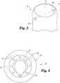
FIG. 3 is a perspective view of a part of the connector ofFIG. 2 showing a passage that receives the conductor. -
FIG. 4 is an elevation view of the location on the back of the interrupter for the conductor to interrupter connection ofFIG. 1 . -
FIG. 5 is a perspective view of the end of the conductor that is positioned in the receptacle of the connector and a part of the bushing that receives the conductor. -
FIG. 6 is an elevation view showing partial insertion of the conductor into the receptacle of the connector. -
FIG. 7 is an elevation view showing final insertion of the conductor into the receptacle of the connector. - For the purposes of promoting an understanding of the principles of the invention, reference will now be made to the embodiments illustrated in the drawings and specific language will be used to describe the same. It will nevertheless be understood that no limitation of the scope of the invention is thereby intended. Any alterations and further modifications in the described embodiments, and any further applications of the principles of the invention as described herein are contemplated as would normally occur to one skilled in the art to which the invention relates. While illustrative embodiments of the invention are described below, in the interest of clarity, not all features of an actual implementation of the invention may be described herein.
- Referring to
FIG. 1 , in the illustrative embodiment, asystem 10 is shown in which an elongated rod is secured to a connector that links the elongated rod to a device. In one embodiment, the elongated rod is aconductor rod 12 and the device is aninterrupter 60 for a circuit breaker (not shown), such as may be employed in a high voltage dead tank circuit breaker. Acoupling system 20 is provided that secures theconductor rod 12 to aconnector 40 that electrically and mechanically links theconductor rod 12 to theinterrupter 60. - Referring further to
FIGs. 2-3 , theconnector 40 includes abase 42 with anextension 44 that defines areceptacle 52 for receiving theconductor rod 12.Base 42 includes an L-shape in the illustrated embodiment, although other shapes are also contemplated. The L-shaped base 42 includes afirst leg 46 and asecond leg 48 extending transversely to thefirst leg 46 away fromextension 44. Theextension 44 extends outwardly fromfirst leg 46 at an oblique angle. Thebottom surface 46a offirst leg 46 can be concavely curved to sit against a curved tank or other curved structure, but other shapes, including non-curved shapes, are also contemplated. Theextension 44 includesaligned bores conductor rod 12, as discussed further below. -
Second leg 48 defines a circular cup shape to fit one the end of theinterrupter 60.Second leg 48 includes a number ofholes 54 in the end plate 56 thereof to receivefasteners 50.Fasteners 50 secure theconnector 40 to theinterrupter 60.
Thesecond leg 48 can be secured to a back or rearward end of theinterrupter 60, as shown inFIG. 1 . - One example of a back end of an
interrupter 60 is shown inFIG. 4 . Theinterrupter 60 may be located in atank 64, and includes arear face 62 for attachment tosecond leg 48 ofconnector 40.Rear face 62 includes a number ofholes 66 that receivefasteners 50 extending thoughsecond leg 48 to secure theconnector 40 to interrupter 60, as shown inFIGs 1 ,6 and 7 . - As shown in
FIG. 1 , thecoupling system 20 includes aswivel member 22 inreceptacle 52, apin 24 extending through theswivel member 22, afastener 26 to which theswivel member 22 is mounted, and a retainer 28 (such as a set screw) for securing thepin 24 in position. Anelectrical contact 30 is positioned around theconductor rod 12. In one embodiment, theelectrical contact 30 is a flexible bracelet that includes multiple linked components of conductive material that are capable of flexing inwardly during insertion ofconductor rod 12 and grip or contact the inner surface ofextension 44 inreceptacle 52 and the outer surface ofconductor rod 12. - Referring to
FIGs. 1 and5 ,swivel member 22 includes acylindrical body 32 with anaxial bore 36 for receivingfastener 26 and atransverse passage 34 extending therethrough for receivingpin 24. Swivelmember 24 further includesinner shoulder 38 that abuts ahead 80 offastener 26 to axially retain theswivel member 24 onfastener 26. Swivelmember 24 also includes anouter shoulder 82 that aligns with afirst end 16 ofconductor rod 12. Swivelmember 24 need not be in abutting engagement withfirst end 16, but such engagement is not precluded. Furthermore,swivel member 24 can be spaced from the inner surfaces ofextension 44 to allow some pivoting ofconductor rod 12 relative toextension 44 transversely longitudinal axis L aboutpin 24. -
Fastener 26 extends into an end opening 18 ofconductor rod 12 along a longitudinal axis L ofconductor rod 12.Fastener 26 can include threads or other suitable structure for engagement withconductor rod 12 to axially restrain theconductor rod 12 to fastener 26. Theswivel member 22 is axially secured toextension 44 withpin 24 extending throughpassage 34 of swivel member and into alignedbores extension 44.Retainer 28 is secured inbore 58a to prevent thepin 24 from becoming dislodged frompassage 34 and bores 58a, 58b. - During assembly, the
swivel member 22 can be secured atfirst end 16 ofconductor rod 12 withfastener 26, as shown inFIG. 5 .Electrical contact 30 is positioned aroundconductor rod 12 adjacent thefirst end 16.Conductor rod 12 can be configured to extend through a bushing, such as bushing 90. As shown inFIG. 6 , the securedswivel member 24 is inserted intoreceptacle 52 ofextension 44, andconductor rod 12 is rotated to alignpassage 34 withbores extension 44. - When the
conductor rod 12 is fully inserted intoextension 44 withpassage 34 aligned withbores pin 24 is inserted intobore 58a, throughpassage 34, and intobore 58b. Thebore 58b can include a stepped profile that only allows partial insertion ofpin 24 therein. Theretainer 28 is then engaged to bore 58a to retain thepin 24 in thebores passage 34.Conductor rod 12 is therefore axially secured toextension 44 ofconnector 40, and electrically linked to theinterrupter 60 via theelectrical contact 30. - Various aspects of the present disclosure are contemplated. According to one aspect, a system includes an elongated rod, a connector including a receptacle for receiving a first end of the elongated rod, and a coupling system in the receptacle of the connector for coupling the elongated rod to the connector. The connector includes a base for connection to a device to be linked with the elongated rod. The coupling system includes a fastener secured to the first end of the elongated rod, a swivel member mounted to the fastener, and a pin securing the swivel member to the connector in the receptacle. An electrical contact positioned around the first end of the elongated rod and in engagement with the connector in the receptacle.
- In one embodiment, the elongated rod includes an axially extending opening in the first end thereof and the fastener is secured to the elongated rod in the opening. In one embodiment, the elongated rod is threadingly engaged to the fastener. In one embodiment, the elongated rod is a conductor and the device is an interrupter for a circuit breaker.
- In one embodiment, the connector includes a tubular extension extending outwardly from the base and the extension defines the receptacle, and the pin is located in a pair of aligned bores of the extension so that the pin extends transversely to the longitudinal axis through the swivel member for engagement in the aligned bores of the extension, and the swivel member can rotate about the pin transversely to the longitudinal axis. In one embodiment, the coupling system includes a retainer engaged to one of the pair of aligned bores for securing the pin to the extension in the aligned bores of the extension.
- In one embodiment, the base is L-shaped and the elongated rod extends outwardly from a first leg of the base and a second leg of the base extends away from the elongated rod transversely to the first leg for connection to the device. In one embodiment, the second leg is cup-shaped and includes an end plate with a number of holes for receiving fasteners to secure the connector to the device. In one embodiment, the electrical contact is a flexible bracelet. In one embodiment, the electrical contact includes multiple spiral/spring contacts.
- In another aspect, a coupling system for connecting a conductor rod to an interrupter is disclosed. The coupling system includes a connector including a receptacle for receiving a first end of the conductor rod and a base for connection to the interrupter. The coupling system also includes a swivel member in the receptacle of the connector and a pin for securing the swivel member to the connector in the receptacle. The coupling system includes a fastener secured to the swivel member in the receptacle and the conductor rod is engageable to the fastener. An electrical contact is positioned around the first end of the elongated rod in engagement with the connector in the receptacle.
- In one embodiment, the fastener is secured in an end opening of the conductor rod. In one embodiment, the fastener is threadingly engaged to the conductor rod.
- In one embodiment, the connector includes a tubular extension extending outwardly from the base and the extension defines the receptacle, and the pin is located in a pair of aligned bores of the extension so that the pin extends transversely to the conductor rod through the swivel member for engagement in the aligned bores. In one embodiment, a retainer is engaged to one of the pair of aligned bores for securing the pin to the extension in the aligned bores.
- In one embodiment, the base is L-shaped and the receptacle extends outwardly from a first leg of the base and the second leg of the base extends transversely to the first leg away from the receptacle. In one embodiment, the electrical contact is a flexible bracelet.
- According to another aspect, a method for connecting a conductor rod to an interrupter includes: engaging a swivel member to a first end of the conductor rod with a fastener; positioning the first end of the conductor rod in a receptacle of a connector so that a passage through the swivel member is aligned with bores of the connector and an electrical contact around the elongated rod is positioned in the receptacle in engagement with the connector; and inserting a pin through the aligned bores of the connector and the passage of the swivel member to axially secure the conductor rod to the connector in the receptacle.
- In one embodiment, the method includes engaging the connector to the interrupter. In one embodiment, the fastener is threadingly engaged in an axially extending bore in the first end of the conductor rod and the swivel member is mounted on an end of the fastener. In one embodiment, the method includes securing the pin in the aligned bores of the connector and the passage of the swivel member with a retainer engaged in one of the bores of the connector.
- While the invention has been illustrated and described in detail in the drawings and foregoing description, the same is to be considered as illustrative and not restrictive in character, it being understood that only the preferred embodiments have been shown and described and that all changes and modifications that come within the spirit of the inventions are desired to be protected. It should be understood that while the use of words such as preferable, preferably, preferred or more preferred utilized in the description above indicate that the feature so described may be more desirable, it nonetheless may not be necessary and embodiments lacking the same may be contemplated as within the scope of the invention, the scope being defined by the claims that follow.
- In reading the claims, it is intended that when words such as "a," "an," "at least one," or "at least one portion" are used there is no intention to limit the claim to only one item unless specifically stated to the contrary in the claim. When the language "at least a portion" and/or "a portion" is used the item can include a portion and/or the entire item unless specifically stated to the contrary. Unless specified or limited otherwise, the terms "mounted," "connected," "supported," and "coupled" and variations thereof are used broadly and encompass both direct and indirect mountings, connections, supports, and couplings. Further, "connected" and "coupled" are not restricted to physical or mechanical connections or couplings.
Claims (20)
- A system comprising:an elongated rod extending along a longitudinal axis from a first end of the elongated rod;a connector including a receptacle for receiving the first end of the elongated rod, the connector including a base for connection to a device to be linked with the elongated rod;a coupling system in the receptacle of the connector for coupling the elongated rod to the connector, the coupling system including:a fastener secured to the first end of the elongated rod;a swivel member mounted to the fastener;a pin securing the swivel member to the connector in the receptacle; andan electrical contact positioned around the first end of the elongated rod and in engagement with the connector in the receptacle.
- The system of claim 1, wherein the elongated rod includes an axially extending opening in the first end thereof and the fastener is secured to the elongated rod in the opening.
- The system of claim 2, wherein the elongated rod is threadingly engaged to the fastener.
- The system of claim 1, wherein the elongated rod is a conductor and the device is an interrupter for a circuit breaker.
- The system of claim 1, wherein the connector includes a tubular extension extending outwardly from the base and the extension defines the receptacle, and the pin is located in a pair of aligned bores of the extension so that the pin extends transversely to the longitudinal axis through the swivel member for engagement in the aligned bores of the extension, wherein the swivel member can rotate about the pin transversely to the longitudinal axis.
- The system of claim 5, wherein the coupling system includes a retainer engaged to one of the pair of aligned bores for securing the pin to the extension in the aligned bores of the extension.
- The system of claim 1, wherein the base is L-shaped and the elongated rod extends outwardly from a first leg of the base and a second leg of the base extends away from the elongated rod transversely to the first leg for connection to the device.
- The system of claim 7, wherein the second leg is cup-shaped and includes an end plate with a number of holes for receiving fasteners to secure the connector to the device.
- The system of claim 1, wherein the electrical contact is a flexible bracelet.
- A coupling system for connecting a conductor rod to an interrupter, the coupling system comprising:a connector including a receptacle for receiving a first end of the conductor rod, the connector including a base for connection to the interrupter;a swivel member in the receptacle of the connector;a pin for securing the swivel member to the connector in the receptacle;a fastener secured to the swivel member in the receptacle, wherein the conductor rod is engageable to the fastener; andan electrical contact positioned around the first end of the elongated rod and in engagement with the connector in the receptacle.
- The coupling system of claim 10, wherein the fastener is secured in an end opening of the conductor rod.
- The coupling system of claim 11, wherein the fastener is threadingly engaged to the conductor rod.
- The coupling system of claim 10, wherein the connector includes a tubular extension extending outwardly from the base and the extension defines the receptacle, and the pin is located in a pair of aligned bores of the extension so that the pin extends transversely to the conductor rod through the swivel member for engagement in the aligned bores.
- The coupling system of claim 13, further comprising a retainer engaged to one of the pair of aligned bores for securing the pin to the extension in the aligned bores.
- The coupling system of claim 10, wherein the base is L-shaped and the receptacle extends outwardly from a first leg of the base and the second leg of the base extends transversely to the first leg away from the receptacle.
- The coupling system of claim 10, wherein the electrical contact is a flexible bracelet.
- A method for connecting a conductor rod to an interrupter, the method comprising:engaging a swivel member to a first end of the conductor rod with a fastener;positioning the first end of the conductor rod in a receptacle of a connector so that a passage through the swivel member is aligned with bores of the connector and an electrical contact around the elongated rod is positioned in the receptacle in engagement with the connector; andinserting a pin through the aligned bores of the connector and the passage of the swivel member to axially secure the conductor rod to the connector in the receptacle.
- The method of claim 17, further comprising engaging the connector to the interrupter.
- The method of claim 17, wherein the fastener is threadingly engaged in an axially extending bore in the first end of the conductor rod and the swivel member is mounted on an end of the fastener.
- The method of claim 17, further comprising securing the pin in the aligned bores of the connector and the passage of the swivel member with a retainer engaged in one of the bores of the connector.
Applications Claiming Priority (1)
| Application Number | Priority Date | Filing Date | Title |
|---|---|---|---|
| US16/842,216 US10978263B1 (en) | 2020-04-07 | 2020-04-07 | Coupling system for interrupter-conductor connection in high voltage circuit breakers |
Publications (2)
| Publication Number | Publication Date |
|---|---|
| EP3893260A1 true EP3893260A1 (en) | 2021-10-13 |
| EP3893260B1 EP3893260B1 (en) | 2024-02-14 |
Family
ID=75339590
Family Applications (1)
| Application Number | Title | Priority Date | Filing Date |
|---|---|---|---|
| EP21166372.9A Active EP3893260B1 (en) | 2020-04-07 | 2021-03-31 | Coupling system for interrupter-conductor connection in high voltage circuit breakers |
Country Status (5)
| Country | Link |
|---|---|
| US (1) | US10978263B1 (en) |
| EP (1) | EP3893260B1 (en) |
| JP (1) | JP7754638B2 (en) |
| CN (1) | CN113496845A (en) |
| CA (1) | CA3113967C (en) |
Families Citing this family (1)
| Publication number | Priority date | Publication date | Assignee | Title |
|---|---|---|---|---|
| JP7090825B1 (en) * | 2021-09-28 | 2022-06-24 | 三菱電機株式会社 | Tank type circuit breaker |
Citations (3)
| Publication number | Priority date | Publication date | Assignee | Title |
|---|---|---|---|---|
| EP1691388A1 (en) * | 2005-02-10 | 2006-08-16 | ABB Technology AG | Plug and socket connector |
| US20130029509A1 (en) * | 2011-07-28 | 2013-01-31 | Abb Technology Ag | Self-locking connector clip |
| US9105427B2 (en) * | 2012-09-14 | 2015-08-11 | Abb Technology Ag | Telescoping current path structure for dual tank dead tank circuit breaker with parallel resistor assembly |
Family Cites Families (12)
| Publication number | Priority date | Publication date | Assignee | Title |
|---|---|---|---|---|
| US3953818A (en) * | 1975-03-28 | 1976-04-27 | A. B. Chance Company | Externally bussed, encapsulated current limiting fuse for pad mounted transformers |
| US4442329A (en) * | 1982-01-04 | 1984-04-10 | Brown Boveri Electric Inc. | Dead tank housing for high voltage circuit breaker employing puffer interrupters |
| US5478980A (en) | 1994-04-05 | 1995-12-26 | Abb Power T&D Company, Inc. | Compact low force dead tank circuit breaker interrupter |
| US5495084A (en) | 1994-04-05 | 1996-02-27 | Abb Power T&D Company Inc. | Slip-through mounting structure for circuit interrupter |
| JP3202551B2 (en) * | 1995-08-08 | 2001-08-27 | 株式会社日立製作所 | Gas circuit breaker |
| JPH09274947A (en) * | 1996-04-08 | 1997-10-21 | Inoue Seisakusho:Kk | Cable junction of equipment direct connection type |
| IT1313732B1 (en) * | 1999-09-15 | 2002-09-17 | Abb Ricerca Spa | INTERRUPT AND SECTIONING EQUIPMENT INSULATED IN GAS |
| FR2807203B1 (en) * | 2000-03-31 | 2002-05-24 | Schneider Electric Ind Sa | CUTTING MODULE COMPRISING A VACUUM BULB AND FIXING MEANS, AND ELECTRICAL CUTTING APPARATUS COMPRISING SUCH A MODULE |
| US6630638B1 (en) | 2000-05-26 | 2003-10-07 | Abb Inc. | Dead tank drawout breakers |
| JP4218216B2 (en) * | 2001-02-22 | 2009-02-04 | 株式会社日立製作所 | Gas circuit breaker |
| WO2003067713A1 (en) | 2002-02-07 | 2003-08-14 | Auto Kabel Managementgesellschaft Mbh | Remakeable connector arrangement |
| US9064647B2 (en) * | 2012-09-06 | 2015-06-23 | Abb Technology Ag | Contact alignment structure for high-voltage dead tank circuit breakers |
-
2020
- 2020-04-07 US US16/842,216 patent/US10978263B1/en active Active
-
2021
- 2021-03-31 EP EP21166372.9A patent/EP3893260B1/en active Active
- 2021-04-01 JP JP2021062946A patent/JP7754638B2/en active Active
- 2021-04-01 CA CA3113967A patent/CA3113967C/en active Active
- 2021-04-07 CN CN202110370380.8A patent/CN113496845A/en active Pending
Patent Citations (3)
| Publication number | Priority date | Publication date | Assignee | Title |
|---|---|---|---|---|
| EP1691388A1 (en) * | 2005-02-10 | 2006-08-16 | ABB Technology AG | Plug and socket connector |
| US20130029509A1 (en) * | 2011-07-28 | 2013-01-31 | Abb Technology Ag | Self-locking connector clip |
| US9105427B2 (en) * | 2012-09-14 | 2015-08-11 | Abb Technology Ag | Telescoping current path structure for dual tank dead tank circuit breaker with parallel resistor assembly |
Also Published As
| Publication number | Publication date |
|---|---|
| US10978263B1 (en) | 2021-04-13 |
| CA3113967C (en) | 2025-02-11 |
| JP2021166179A (en) | 2021-10-14 |
| CA3113967A1 (en) | 2021-10-07 |
| CN113496845A (en) | 2021-10-12 |
| EP3893260B1 (en) | 2024-02-14 |
| JP7754638B2 (en) | 2025-10-15 |
Similar Documents
| Publication | Publication Date | Title |
|---|---|---|
| US7311566B2 (en) | Electrical connectors | |
| US8597050B2 (en) | Digital, small signal and RF microwave coaxial subminiature push-on differential pair system | |
| CA2461041C (en) | Socket contact with integrally formed arc arresting portion | |
| ES2671240T3 (en) | Electrical connector with grounding mechanism | |
| US8632356B2 (en) | Electrical plug connector | |
| US5676571A (en) | Socket contact with integrally formed hood and arc-arresting portion | |
| US5221220A (en) | Standoff bushing assembly | |
| AU713888B2 (en) | Printed circuit board to housing interconnect system | |
| US9954315B2 (en) | Grounding link for electrical connector mechanism | |
| US7347726B2 (en) | Push-on connector interface | |
| US7841906B2 (en) | Electrical connectors | |
| WO2005084281A3 (en) | Hermetic electrical connector | |
| US4203641A (en) | Double bushing insert | |
| CA3113967C (en) | Coupling system for interrupter-conductor connection in high voltage circuit breakers | |
| EP2140523A1 (en) | High current sealed connector plug assembly | |
| US7588469B2 (en) | Safely separating electrical connecting system | |
| KR102530543B1 (en) | coaxial rf connector | |
| US20120214336A1 (en) | Electrical connector with sacrificial appendage | |
| EP1215758A2 (en) | A device for joining cables to an appliance connection | |
| GB1285608A (en) | Electrical connectors | |
| US10971842B2 (en) | Loadbreak electrical connector with enhanced safety probe | |
| JP2021166179A5 (en) | ||
| CN223390778U (en) | Connection terminal | |
| US20240063568A1 (en) | Electrical connector assembly with coil spring terminal | |
| AU2016204978B2 (en) | Electrical plug and socket assembly |
Legal Events
| Date | Code | Title | Description |
|---|---|---|---|
| PUAI | Public reference made under article 153(3) epc to a published international application that has entered the european phase |
Free format text: ORIGINAL CODE: 0009012 |
|
| STAA | Information on the status of an ep patent application or granted ep patent |
Free format text: STATUS: THE APPLICATION HAS BEEN PUBLISHED |
|
| AK | Designated contracting states |
Kind code of ref document: A1 Designated state(s): AL AT BE BG CH CY CZ DE DK EE ES FI FR GB GR HR HU IE IS IT LI LT LU LV MC MK MT NL NO PL PT RO RS SE SI SK SM TR |
|
| RAP3 | Party data changed (applicant data changed or rights of an application transferred) |
Owner name: HITACHI ENERGY SWITZERLAND AG |
|
| STAA | Information on the status of an ep patent application or granted ep patent |
Free format text: STATUS: REQUEST FOR EXAMINATION WAS MADE |
|
| 17P | Request for examination filed |
Effective date: 20220413 |
|
| RBV | Designated contracting states (corrected) |
Designated state(s): AL AT BE BG CH CY CZ DE DK EE ES FI FR GB GR HR HU IE IS IT LI LT LU LV MC MK MT NL NO PL PT RO RS SE SI SK SM TR |
|
| P01 | Opt-out of the competence of the unified patent court (upc) registered |
Effective date: 20230527 |
|
| GRAP | Despatch of communication of intention to grant a patent |
Free format text: ORIGINAL CODE: EPIDOSNIGR1 |
|
| STAA | Information on the status of an ep patent application or granted ep patent |
Free format text: STATUS: GRANT OF PATENT IS INTENDED |
|
| RIC1 | Information provided on ipc code assigned before grant |
Ipc: H01R 13/639 20060101ALI20230808BHEP Ipc: H01H 33/02 20060101AFI20230808BHEP |
|
| INTG | Intention to grant announced |
Effective date: 20230906 |
|
| RAP1 | Party data changed (applicant data changed or rights of an application transferred) |
Owner name: HITACHI ENERGY LTD |
|
| GRAS | Grant fee paid |
Free format text: ORIGINAL CODE: EPIDOSNIGR3 |
|
| GRAA | (expected) grant |
Free format text: ORIGINAL CODE: 0009210 |
|
| STAA | Information on the status of an ep patent application or granted ep patent |
Free format text: STATUS: THE PATENT HAS BEEN GRANTED |
|
| AK | Designated contracting states |
Kind code of ref document: B1 Designated state(s): AL AT BE BG CH CY CZ DE DK EE ES FI FR GB GR HR HU IE IS IT LI LT LU LV MC MK MT NL NO PL PT RO RS SE SI SK SM TR |
|
| REG | Reference to a national code |
Ref country code: GB Ref legal event code: FG4D |
|
| REG | Reference to a national code |
Ref country code: CH Ref legal event code: EP |
|
| REG | Reference to a national code |
Ref country code: DE Ref legal event code: R096 Ref document number: 602021009290 Country of ref document: DE |
|
| REG | Reference to a national code |
Ref country code: IE Ref legal event code: FG4D |
|
| REG | Reference to a national code |
Ref country code: LT Ref legal event code: MG9D |
|
| REG | Reference to a national code |
Ref country code: NL Ref legal event code: MP Effective date: 20240214 |
|
| PG25 | Lapsed in a contracting state [announced via postgrant information from national office to epo] |
Ref country code: IS Free format text: LAPSE BECAUSE OF FAILURE TO SUBMIT A TRANSLATION OF THE DESCRIPTION OR TO PAY THE FEE WITHIN THE PRESCRIBED TIME-LIMIT Effective date: 20240614 |
|
| PG25 | Lapsed in a contracting state [announced via postgrant information from national office to epo] |
Ref country code: LT Free format text: LAPSE BECAUSE OF FAILURE TO SUBMIT A TRANSLATION OF THE DESCRIPTION OR TO PAY THE FEE WITHIN THE PRESCRIBED TIME-LIMIT Effective date: 20240214 |
|
| PG25 | Lapsed in a contracting state [announced via postgrant information from national office to epo] |
Ref country code: GR Free format text: LAPSE BECAUSE OF FAILURE TO SUBMIT A TRANSLATION OF THE DESCRIPTION OR TO PAY THE FEE WITHIN THE PRESCRIBED TIME-LIMIT Effective date: 20240515 |
|
| REG | Reference to a national code |
Ref country code: AT Ref legal event code: MK05 Ref document number: 1657781 Country of ref document: AT Kind code of ref document: T Effective date: 20240214 |
|
| PG25 | Lapsed in a contracting state [announced via postgrant information from national office to epo] |
Ref country code: HR Free format text: LAPSE BECAUSE OF FAILURE TO SUBMIT A TRANSLATION OF THE DESCRIPTION OR TO PAY THE FEE WITHIN THE PRESCRIBED TIME-LIMIT Effective date: 20240214 Ref country code: NL Free format text: LAPSE BECAUSE OF FAILURE TO SUBMIT A TRANSLATION OF THE DESCRIPTION OR TO PAY THE FEE WITHIN THE PRESCRIBED TIME-LIMIT Effective date: 20240214 Ref country code: RS Free format text: LAPSE BECAUSE OF FAILURE TO SUBMIT A TRANSLATION OF THE DESCRIPTION OR TO PAY THE FEE WITHIN THE PRESCRIBED TIME-LIMIT Effective date: 20240514 |
|
| PG25 | Lapsed in a contracting state [announced via postgrant information from national office to epo] |
Ref country code: ES Free format text: LAPSE BECAUSE OF FAILURE TO SUBMIT A TRANSLATION OF THE DESCRIPTION OR TO PAY THE FEE WITHIN THE PRESCRIBED TIME-LIMIT Effective date: 20240214 |
|
| PG25 | Lapsed in a contracting state [announced via postgrant information from national office to epo] |
Ref country code: AT Free format text: LAPSE BECAUSE OF FAILURE TO SUBMIT A TRANSLATION OF THE DESCRIPTION OR TO PAY THE FEE WITHIN THE PRESCRIBED TIME-LIMIT Effective date: 20240214 |
|
| PG25 | Lapsed in a contracting state [announced via postgrant information from national office to epo] |
Ref country code: RS Free format text: LAPSE BECAUSE OF FAILURE TO SUBMIT A TRANSLATION OF THE DESCRIPTION OR TO PAY THE FEE WITHIN THE PRESCRIBED TIME-LIMIT Effective date: 20240514 Ref country code: NO Free format text: LAPSE BECAUSE OF FAILURE TO SUBMIT A TRANSLATION OF THE DESCRIPTION OR TO PAY THE FEE WITHIN THE PRESCRIBED TIME-LIMIT Effective date: 20240514 Ref country code: NL Free format text: LAPSE BECAUSE OF FAILURE TO SUBMIT A TRANSLATION OF THE DESCRIPTION OR TO PAY THE FEE WITHIN THE PRESCRIBED TIME-LIMIT Effective date: 20240214 Ref country code: LT Free format text: LAPSE BECAUSE OF FAILURE TO SUBMIT A TRANSLATION OF THE DESCRIPTION OR TO PAY THE FEE WITHIN THE PRESCRIBED TIME-LIMIT Effective date: 20240214 Ref country code: IS Free format text: LAPSE BECAUSE OF FAILURE TO SUBMIT A TRANSLATION OF THE DESCRIPTION OR TO PAY THE FEE WITHIN THE PRESCRIBED TIME-LIMIT Effective date: 20240614 Ref country code: HR Free format text: LAPSE BECAUSE OF FAILURE TO SUBMIT A TRANSLATION OF THE DESCRIPTION OR TO PAY THE FEE WITHIN THE PRESCRIBED TIME-LIMIT Effective date: 20240214 Ref country code: GR Free format text: LAPSE BECAUSE OF FAILURE TO SUBMIT A TRANSLATION OF THE DESCRIPTION OR TO PAY THE FEE WITHIN THE PRESCRIBED TIME-LIMIT Effective date: 20240515 Ref country code: FI Free format text: LAPSE BECAUSE OF FAILURE TO SUBMIT A TRANSLATION OF THE DESCRIPTION OR TO PAY THE FEE WITHIN THE PRESCRIBED TIME-LIMIT Effective date: 20240214 Ref country code: ES Free format text: LAPSE BECAUSE OF FAILURE TO SUBMIT A TRANSLATION OF THE DESCRIPTION OR TO PAY THE FEE WITHIN THE PRESCRIBED TIME-LIMIT Effective date: 20240214 Ref country code: BG Free format text: LAPSE BECAUSE OF FAILURE TO SUBMIT A TRANSLATION OF THE DESCRIPTION OR TO PAY THE FEE WITHIN THE PRESCRIBED TIME-LIMIT Effective date: 20240214 Ref country code: AT Free format text: LAPSE BECAUSE OF FAILURE TO SUBMIT A TRANSLATION OF THE DESCRIPTION OR TO PAY THE FEE WITHIN THE PRESCRIBED TIME-LIMIT Effective date: 20240214 |
|
| PG25 | Lapsed in a contracting state [announced via postgrant information from national office to epo] |
Ref country code: PT Free format text: LAPSE BECAUSE OF FAILURE TO SUBMIT A TRANSLATION OF THE DESCRIPTION OR TO PAY THE FEE WITHIN THE PRESCRIBED TIME-LIMIT Effective date: 20240614 Ref country code: PL Free format text: LAPSE BECAUSE OF FAILURE TO SUBMIT A TRANSLATION OF THE DESCRIPTION OR TO PAY THE FEE WITHIN THE PRESCRIBED TIME-LIMIT Effective date: 20240214 |
|
| PG25 | Lapsed in a contracting state [announced via postgrant information from national office to epo] |
Ref country code: SE Free format text: LAPSE BECAUSE OF FAILURE TO SUBMIT A TRANSLATION OF THE DESCRIPTION OR TO PAY THE FEE WITHIN THE PRESCRIBED TIME-LIMIT Effective date: 20240214 Ref country code: PT Free format text: LAPSE BECAUSE OF FAILURE TO SUBMIT A TRANSLATION OF THE DESCRIPTION OR TO PAY THE FEE WITHIN THE PRESCRIBED TIME-LIMIT Effective date: 20240614 Ref country code: PL Free format text: LAPSE BECAUSE OF FAILURE TO SUBMIT A TRANSLATION OF THE DESCRIPTION OR TO PAY THE FEE WITHIN THE PRESCRIBED TIME-LIMIT Effective date: 20240214 Ref country code: LV Free format text: LAPSE BECAUSE OF FAILURE TO SUBMIT A TRANSLATION OF THE DESCRIPTION OR TO PAY THE FEE WITHIN THE PRESCRIBED TIME-LIMIT Effective date: 20240214 |
|
| PG25 | Lapsed in a contracting state [announced via postgrant information from national office to epo] |
Ref country code: DK Free format text: LAPSE BECAUSE OF FAILURE TO SUBMIT A TRANSLATION OF THE DESCRIPTION OR TO PAY THE FEE WITHIN THE PRESCRIBED TIME-LIMIT Effective date: 20240214 |
|
| PG25 | Lapsed in a contracting state [announced via postgrant information from national office to epo] |
Ref country code: SM Free format text: LAPSE BECAUSE OF FAILURE TO SUBMIT A TRANSLATION OF THE DESCRIPTION OR TO PAY THE FEE WITHIN THE PRESCRIBED TIME-LIMIT Effective date: 20240214 |
|
| PG25 | Lapsed in a contracting state [announced via postgrant information from national office to epo] |
Ref country code: EE Free format text: LAPSE BECAUSE OF FAILURE TO SUBMIT A TRANSLATION OF THE DESCRIPTION OR TO PAY THE FEE WITHIN THE PRESCRIBED TIME-LIMIT Effective date: 20240214 Ref country code: CZ Free format text: LAPSE BECAUSE OF FAILURE TO SUBMIT A TRANSLATION OF THE DESCRIPTION OR TO PAY THE FEE WITHIN THE PRESCRIBED TIME-LIMIT Effective date: 20240214 |
|
| PG25 | Lapsed in a contracting state [announced via postgrant information from national office to epo] |
Ref country code: SK Free format text: LAPSE BECAUSE OF FAILURE TO SUBMIT A TRANSLATION OF THE DESCRIPTION OR TO PAY THE FEE WITHIN THE PRESCRIBED TIME-LIMIT Effective date: 20240214 |
|
| PG25 | Lapsed in a contracting state [announced via postgrant information from national office to epo] |
Ref country code: SM Free format text: LAPSE BECAUSE OF FAILURE TO SUBMIT A TRANSLATION OF THE DESCRIPTION OR TO PAY THE FEE WITHIN THE PRESCRIBED TIME-LIMIT Effective date: 20240214 Ref country code: SK Free format text: LAPSE BECAUSE OF FAILURE TO SUBMIT A TRANSLATION OF THE DESCRIPTION OR TO PAY THE FEE WITHIN THE PRESCRIBED TIME-LIMIT Effective date: 20240214 Ref country code: RO Free format text: LAPSE BECAUSE OF FAILURE TO SUBMIT A TRANSLATION OF THE DESCRIPTION OR TO PAY THE FEE WITHIN THE PRESCRIBED TIME-LIMIT Effective date: 20240214 Ref country code: EE Free format text: LAPSE BECAUSE OF FAILURE TO SUBMIT A TRANSLATION OF THE DESCRIPTION OR TO PAY THE FEE WITHIN THE PRESCRIBED TIME-LIMIT Effective date: 20240214 Ref country code: DK Free format text: LAPSE BECAUSE OF FAILURE TO SUBMIT A TRANSLATION OF THE DESCRIPTION OR TO PAY THE FEE WITHIN THE PRESCRIBED TIME-LIMIT Effective date: 20240214 Ref country code: CZ Free format text: LAPSE BECAUSE OF FAILURE TO SUBMIT A TRANSLATION OF THE DESCRIPTION OR TO PAY THE FEE WITHIN THE PRESCRIBED TIME-LIMIT Effective date: 20240214 |
|
| REG | Reference to a national code |
Ref country code: CH Ref legal event code: PL |
|
| REG | Reference to a national code |
Ref country code: DE Ref legal event code: R097 Ref document number: 602021009290 Country of ref document: DE |
|
| PG25 | Lapsed in a contracting state [announced via postgrant information from national office to epo] |
Ref country code: LU Free format text: LAPSE BECAUSE OF NON-PAYMENT OF DUE FEES Effective date: 20240331 |
|
| PG25 | Lapsed in a contracting state [announced via postgrant information from national office to epo] |
Ref country code: MC Free format text: LAPSE BECAUSE OF FAILURE TO SUBMIT A TRANSLATION OF THE DESCRIPTION OR TO PAY THE FEE WITHIN THE PRESCRIBED TIME-LIMIT Effective date: 20240214 |
|
| PG25 | Lapsed in a contracting state [announced via postgrant information from national office to epo] |
Ref country code: MC Free format text: LAPSE BECAUSE OF FAILURE TO SUBMIT A TRANSLATION OF THE DESCRIPTION OR TO PAY THE FEE WITHIN THE PRESCRIBED TIME-LIMIT Effective date: 20240214 Ref country code: LU Free format text: LAPSE BECAUSE OF NON-PAYMENT OF DUE FEES Effective date: 20240331 |
|
| PG25 | Lapsed in a contracting state [announced via postgrant information from national office to epo] |
Ref country code: IT Free format text: LAPSE BECAUSE OF FAILURE TO SUBMIT A TRANSLATION OF THE DESCRIPTION OR TO PAY THE FEE WITHIN THE PRESCRIBED TIME-LIMIT Effective date: 20240214 |
|
| REG | Reference to a national code |
Ref country code: BE Ref legal event code: MM Effective date: 20240331 |
|
| PLBE | No opposition filed within time limit |
Free format text: ORIGINAL CODE: 0009261 |
|
| STAA | Information on the status of an ep patent application or granted ep patent |
Free format text: STATUS: NO OPPOSITION FILED WITHIN TIME LIMIT |
|
| PG25 | Lapsed in a contracting state [announced via postgrant information from national office to epo] |
Ref country code: IT Free format text: LAPSE BECAUSE OF FAILURE TO SUBMIT A TRANSLATION OF THE DESCRIPTION OR TO PAY THE FEE WITHIN THE PRESCRIBED TIME-LIMIT Effective date: 20240214 |
|
| PG25 | Lapsed in a contracting state [announced via postgrant information from national office to epo] |
Ref country code: BE Free format text: LAPSE BECAUSE OF NON-PAYMENT OF DUE FEES Effective date: 20240331 |
|
| PG25 | Lapsed in a contracting state [announced via postgrant information from national office to epo] |
Ref country code: FR Free format text: LAPSE BECAUSE OF NON-PAYMENT OF DUE FEES Effective date: 20240414 |
|
| 26N | No opposition filed |
Effective date: 20241115 |
|
| PG25 | Lapsed in a contracting state [announced via postgrant information from national office to epo] |
Ref country code: IE Free format text: LAPSE BECAUSE OF NON-PAYMENT OF DUE FEES Effective date: 20240331 |
|
| PG25 | Lapsed in a contracting state [announced via postgrant information from national office to epo] |
Ref country code: IE Free format text: LAPSE BECAUSE OF NON-PAYMENT OF DUE FEES Effective date: 20240331 Ref country code: FR Free format text: LAPSE BECAUSE OF NON-PAYMENT OF DUE FEES Effective date: 20240414 Ref country code: BE Free format text: LAPSE BECAUSE OF NON-PAYMENT OF DUE FEES Effective date: 20240331 Ref country code: CH Free format text: LAPSE BECAUSE OF NON-PAYMENT OF DUE FEES Effective date: 20240331 |
|
| PG25 | Lapsed in a contracting state [announced via postgrant information from national office to epo] |
Ref country code: SI Free format text: LAPSE BECAUSE OF FAILURE TO SUBMIT A TRANSLATION OF THE DESCRIPTION OR TO PAY THE FEE WITHIN THE PRESCRIBED TIME-LIMIT Effective date: 20240214 |
|
| PG25 | Lapsed in a contracting state [announced via postgrant information from national office to epo] |
Ref country code: CY Free format text: LAPSE BECAUSE OF FAILURE TO SUBMIT A TRANSLATION OF THE DESCRIPTION OR TO PAY THE FEE WITHIN THE PRESCRIBED TIME-LIMIT; INVALID AB INITIO Effective date: 20210331 |
|
| PG25 | Lapsed in a contracting state [announced via postgrant information from national office to epo] |
Ref country code: HU Free format text: LAPSE BECAUSE OF FAILURE TO SUBMIT A TRANSLATION OF THE DESCRIPTION OR TO PAY THE FEE WITHIN THE PRESCRIBED TIME-LIMIT; INVALID AB INITIO Effective date: 20210331 |
|
| PG25 | Lapsed in a contracting state [announced via postgrant information from national office to epo] |
Ref country code: TR Free format text: LAPSE BECAUSE OF FAILURE TO SUBMIT A TRANSLATION OF THE DESCRIPTION OR TO PAY THE FEE WITHIN THE PRESCRIBED TIME-LIMIT Effective date: 20240214 |
|
| PGFP | Annual fee paid to national office [announced via postgrant information from national office to epo] |
Ref country code: GB Payment date: 20260324 Year of fee payment: 6 |
|
| PGFP | Annual fee paid to national office [announced via postgrant information from national office to epo] |
Ref country code: DE Payment date: 20260319 Year of fee payment: 6 |