EP3893077A1 - Control device, movement control system, control method, and program - Google Patents
Control device, movement control system, control method, and program Download PDFInfo
- Publication number
- EP3893077A1 EP3893077A1 EP21165503.0A EP21165503A EP3893077A1 EP 3893077 A1 EP3893077 A1 EP 3893077A1 EP 21165503 A EP21165503 A EP 21165503A EP 3893077 A1 EP3893077 A1 EP 3893077A1
- Authority
- EP
- European Patent Office
- Prior art keywords
- movable body
- information
- pallet
- target
- truck
- Prior art date
- Legal status (The legal status is an assumption and is not a legal conclusion. Google has not performed a legal analysis and makes no representation as to the accuracy of the status listed.)
- Granted
Links
Images








Classifications
-
- G—PHYSICS
- G05—CONTROLLING; REGULATING
- G05D—SYSTEMS FOR CONTROLLING OR REGULATING NON-ELECTRIC VARIABLES
- G05D1/00—Control of position, course, altitude or attitude of land, water, air or space vehicles, e.g. using automatic pilots
- G05D1/02—Control of position or course in two dimensions
- G05D1/021—Control of position or course in two dimensions specially adapted to land vehicles
- G05D1/0212—Control of position or course in two dimensions specially adapted to land vehicles with means for defining a desired trajectory
- G05D1/0225—Control of position or course in two dimensions specially adapted to land vehicles with means for defining a desired trajectory involving docking at a fixed facility, e.g. base station or loading bay
-
- G—PHYSICS
- G05—CONTROLLING; REGULATING
- G05D—SYSTEMS FOR CONTROLLING OR REGULATING NON-ELECTRIC VARIABLES
- G05D1/00—Control of position, course, altitude or attitude of land, water, air or space vehicles, e.g. using automatic pilots
- G05D1/02—Control of position or course in two dimensions
- G05D1/021—Control of position or course in two dimensions specially adapted to land vehicles
- G05D1/0231—Control of position or course in two dimensions specially adapted to land vehicles using optical position detecting means
- G05D1/0234—Control of position or course in two dimensions specially adapted to land vehicles using optical position detecting means using optical markers or beacons
- G05D1/0236—Control of position or course in two dimensions specially adapted to land vehicles using optical position detecting means using optical markers or beacons in combination with a laser
-
- B—PERFORMING OPERATIONS; TRANSPORTING
- B66—HOISTING; LIFTING; HAULING
- B66F—HOISTING, LIFTING, HAULING OR PUSHING, NOT OTHERWISE PROVIDED FOR, e.g. DEVICES WHICH APPLY A LIFTING OR PUSHING FORCE DIRECTLY TO THE SURFACE OF A LOAD
- B66F9/00—Devices for lifting or lowering bulky or heavy goods for loading or unloading purposes
- B66F9/06—Devices for lifting or lowering bulky or heavy goods for loading or unloading purposes movable, with their loads, on wheels or the like, e.g. fork-lift trucks
- B66F9/063—Automatically guided
-
- B—PERFORMING OPERATIONS; TRANSPORTING
- B66—HOISTING; LIFTING; HAULING
- B66F—HOISTING, LIFTING, HAULING OR PUSHING, NOT OTHERWISE PROVIDED FOR, e.g. DEVICES WHICH APPLY A LIFTING OR PUSHING FORCE DIRECTLY TO THE SURFACE OF A LOAD
- B66F9/00—Devices for lifting or lowering bulky or heavy goods for loading or unloading purposes
- B66F9/06—Devices for lifting or lowering bulky or heavy goods for loading or unloading purposes movable, with their loads, on wheels or the like, e.g. fork-lift trucks
- B66F9/075—Constructional features or details
- B66F9/0755—Position control; Position detectors
-
- B—PERFORMING OPERATIONS; TRANSPORTING
- B66—HOISTING; LIFTING; HAULING
- B66F—HOISTING, LIFTING, HAULING OR PUSHING, NOT OTHERWISE PROVIDED FOR, e.g. DEVICES WHICH APPLY A LIFTING OR PUSHING FORCE DIRECTLY TO THE SURFACE OF A LOAD
- B66F9/00—Devices for lifting or lowering bulky or heavy goods for loading or unloading purposes
- B66F9/06—Devices for lifting or lowering bulky or heavy goods for loading or unloading purposes movable, with their loads, on wheels or the like, e.g. fork-lift trucks
- B66F9/075—Constructional features or details
- B66F9/07581—Remote controls
-
- B—PERFORMING OPERATIONS; TRANSPORTING
- B66—HOISTING; LIFTING; HAULING
- B66F—HOISTING, LIFTING, HAULING OR PUSHING, NOT OTHERWISE PROVIDED FOR, e.g. DEVICES WHICH APPLY A LIFTING OR PUSHING FORCE DIRECTLY TO THE SURFACE OF A LOAD
- B66F9/00—Devices for lifting or lowering bulky or heavy goods for loading or unloading purposes
- B66F9/06—Devices for lifting or lowering bulky or heavy goods for loading or unloading purposes movable, with their loads, on wheels or the like, e.g. fork-lift trucks
- B66F9/075—Constructional features or details
- B66F9/20—Means for actuating or controlling masts, platforms, or forks
- B66F9/24—Electrical devices or systems
-
- G—PHYSICS
- G05—CONTROLLING; REGULATING
- G05D—SYSTEMS FOR CONTROLLING OR REGULATING NON-ELECTRIC VARIABLES
- G05D1/00—Control of position, course, altitude or attitude of land, water, air or space vehicles, e.g. using automatic pilots
- G05D1/02—Control of position or course in two dimensions
- G05D1/021—Control of position or course in two dimensions specially adapted to land vehicles
- G05D1/0212—Control of position or course in two dimensions specially adapted to land vehicles with means for defining a desired trajectory
- G05D1/0214—Control of position or course in two dimensions specially adapted to land vehicles with means for defining a desired trajectory in accordance with safety or protection criteria, e.g. avoiding hazardous areas
-
- G—PHYSICS
- G05—CONTROLLING; REGULATING
- G05D—SYSTEMS FOR CONTROLLING OR REGULATING NON-ELECTRIC VARIABLES
- G05D1/00—Control of position, course, altitude or attitude of land, water, air or space vehicles, e.g. using automatic pilots
- G05D1/02—Control of position or course in two dimensions
- G05D1/021—Control of position or course in two dimensions specially adapted to land vehicles
- G05D1/0212—Control of position or course in two dimensions specially adapted to land vehicles with means for defining a desired trajectory
- G05D1/0223—Control of position or course in two dimensions specially adapted to land vehicles with means for defining a desired trajectory involving speed control of the vehicle
-
- G—PHYSICS
- G05—CONTROLLING; REGULATING
- G05D—SYSTEMS FOR CONTROLLING OR REGULATING NON-ELECTRIC VARIABLES
- G05D1/00—Control of position, course, altitude or attitude of land, water, air or space vehicles, e.g. using automatic pilots
- G05D1/02—Control of position or course in two dimensions
- G05D1/021—Control of position or course in two dimensions specially adapted to land vehicles
- G05D1/0231—Control of position or course in two dimensions specially adapted to land vehicles using optical position detecting means
- G05D1/0234—Control of position or course in two dimensions specially adapted to land vehicles using optical position detecting means using optical markers or beacons
-
- G—PHYSICS
- G05—CONTROLLING; REGULATING
- G05D—SYSTEMS FOR CONTROLLING OR REGULATING NON-ELECTRIC VARIABLES
- G05D1/00—Control of position, course, altitude or attitude of land, water, air or space vehicles, e.g. using automatic pilots
- G05D1/02—Control of position or course in two dimensions
- G05D1/021—Control of position or course in two dimensions specially adapted to land vehicles
- G05D1/0231—Control of position or course in two dimensions specially adapted to land vehicles using optical position detecting means
- G05D1/0246—Control of position or course in two dimensions specially adapted to land vehicles using optical position detecting means using a video camera in combination with image processing means
- G05D1/0253—Control of position or course in two dimensions specially adapted to land vehicles using optical position detecting means using a video camera in combination with image processing means extracting relative motion information from a plurality of images taken successively, e.g. visual odometry, optical flow
-
- G—PHYSICS
- G05—CONTROLLING; REGULATING
- G05D—SYSTEMS FOR CONTROLLING OR REGULATING NON-ELECTRIC VARIABLES
- G05D1/00—Control of position, course, altitude or attitude of land, water, air or space vehicles, e.g. using automatic pilots
- G05D1/02—Control of position or course in two dimensions
- G05D1/021—Control of position or course in two dimensions specially adapted to land vehicles
- G05D1/0276—Control of position or course in two dimensions specially adapted to land vehicles using signals provided by a source external to the vehicle
Definitions
- the present invention relates to a control device, a movement control system, a control method, and a program.
- a technology has been known that detects the position of a load that is an object to be transported and automatically picks up and moves the load to a target position.
- a control device is described which detects a label attached to a load, identifies the position of the load, and controls the position of a movable body to pick up the load.
- Patent Literature 1 JP 2003-212489 A
- an object such as a load may be placed in a position deviated from a presumed installation position. Further, when an object is transported to a truck or the like, and the stop position of the truck deviates from a presumed position, the object cannot be transported to a presumed position in the truck.
- the correct position can be detected by detecting a marker of the object, but processing of detecting the marker is executed every time, so that there is a limit to the improvement of work efficiency.
- the present disclosure is intended to solve the above-described problems, and an object of the present disclosure is to provide a control device, a movement control system, a control method, and a program capable of transporting an object efficiently with high accuracy.
- a control device for outputting information to a movable body configured to move automatically, the control device including a route acquisition unit configured to acquire a route of the movable body for moving a plurality of aligned target objects to or from a target position at which the target objects are picked up or dropped; a reference position/posture acquisition unit configured to acquire information on a position at which the movable body picks up or drops a first target object of the plurality of target objects at the target position; and an information output unit configured to output the information acquired by the route acquisition unit to the movable body, in which the route acquisition unit acquires routes of the movable body for moving second and subsequent target objects of the plurality of target objects, based on the information acquired by the reference position/posture acquisition unit.
- a movement control system includes the computation device and the movable body.
- a control method is a control method of a movable body configured to transport a plurality of aligned target objects to or from a target position, the control method comprising: acquiring information on a position for picking up or dropping a first target object of the plurality of target objects at the target position; acquiring routes of the movable body for moving second and subsequent target objects of the plurality of target objects, based on the information on the position for picking up or dropping the first target object; and outputting the acquired routes of the movable body.
- a program according to the present disclosure is a program for causing a computer to execute a control method of a movable body configured to transport a plurality of aligned target objects to or from a target position, the program causing the computer to execute: acquiring information on a position for picking up or dropping a first target object of the plurality of target objects at the target position; acquiring routes of the movable body for moving second and subsequent target objects of the plurality of target objects, based on the information on the position for picking up or dropping the first target object; and outputting the acquired routes of the movable body.
- objects can be transported efficiently with high accuracy.
- FIG. 1 is a schematic view of a movement control system according to a first embodiment.
- a movement control system 1 according to the first embodiment includes a movable body 10, a management system 12, and a computation device 14.
- the movement control system 1 is a system that controls movement of the movable body 10 that belongs to a facility W.
- the facility W is a facility that is logistically managed, such as a warehouse.
- a truck V is stopped in an area Ar.
- the movement control system 1 picks up a pallet (load) P mounted on the truck (vehicle) V with the movable body 10, and drops the pallet P in a predetermined standby position.
- the movement control system 1 also picks up a pallet P disposed in a predetermined standby position with the movable body 10, and drops the pallet P in the truck V. In other words, the movement control system 1 performs unloading work or loading work of the pallet P from or on the truck V.
- the area Ar is an area which is set as a stop position of the truck V, and is divided by, for example, a white line or the like. An area where the movable body 10 moves is provided around the area Ar.
- the standby place can be provided at any place of the facility W. Further, although only one area Ar is illustrated in the facility W of the present embodiment, a plurality of the areas Ar may be disposed. Further, the number of the movable bodies 10 is not limited to two, and may be one or three or more.
- FIG. 2 is a schematic view illustrating a schematic configuration of the truck.
- the truck V of the present embodiment is a vehicle that travels by driving a plurality of tires VE.
- the truck V is a vehicle on which a plurality of pallets P can be mounted. In the truck V illustrated in FIG. 1 , four pallets P are arranged in two rows.
- the pallets P are mounted in the storage chamber VA of the truck V, as illustrated in FIG. 2 .
- the truck V includes a side door VB.
- the side door VB is a door provided on each side of the storage chamber VA.
- the side door VB of the truck V is opened to allow the storage chamber VA to communicate with the exterior, so that the pallets P can be carried out.
- the truck V of the present embodiment includes a position in the storage chamber VA where the pallets P are held.
- the plurality of pallets P are arranged side-by-side within the storage chamber VA of the truck V.
- the pallets are arranged in two rows in the storage chamber VA. Note that there are various arrangement patterns such as a case where the pallets are placed without intervals therebetween on the front side of the truck, a case where the pallets are placed without intervals therebetween on the rear side, or a case where the pallets placed in the storage chamber VA at intervals.
- the truck V of the present embodiment includes the side doors VB on both sides, and the movable body 10 can access the pallets P from each of the two side.
- the truck V of the present embodiment has a structure in which each side door VB is a rigid body and opens and closes vertically, but the side door VB may also be a curtain type door formed of a deforming fabric or plastic which opens and closes by moving its one end horizontally.
- the movable body 10 is an automatically movable device.
- the movable body 10 is a forklift, so called an Automated Guided Forklift (AGF) or Automated Guided Vehicle (AGV).
- AMF Automated Guided Forklift
- AGV Automated Guided Vehicle
- the movable body 10 moves within the facility W.
- the movable body 10 moves to the vicinity of the truck V, for example, along a route R.
- the route R is information transmitted from the computation device 14.
- the movable body 10 moves based on the set route and picks up each pallet P, based on the position information on the pallet P.
- the route R will be described in detail below.
- direction X one horizontal direction
- a direction orthogonal to the direction X in the horizontal direction is referred to as a direction Y
- direction Z the direction orthogonal to the horizontal direction, that is, the direction orthogonal to the directions X and Y, is referred to as a direction Z.
- FIG. 3 is a schematic view of a configuration of the movable body.
- the movable body 10 includes a vehicle body 20, a mast 22, a fork 24, a sensor 26, and a control device 28.
- the vehicle body 20 includes a wheel 20A.
- the mast 22 is provided at one end portion in the front-back direction of the vehicle body 20.
- the mast 22 extends along a vertical direction (here, the direction Z) orthogonal to the front-back direction.
- the fork 24 is attached to the mast 22 in a manner movable in the direction Z.
- the fork 24 may be movable with respect to the mast 22 in the lateral direction of the vehicle body 20 (the direction intersecting the vertical direction and the front-back direction).
- the fork 24 includes a pair of tabs 24A, 24B.
- the tabs 24A, 24B extend from the mast 22 toward the front direction of the vehicle body 20.
- the tabs 24A, 24B are disposed away from each other in the lateral direction of the mast 22.
- the direction where the fork 24 is provided in the movable body 10 is referred to as a first direction
- the direction where the fork 24 is not provided is referred to as a second direction.
- the sensor 26 detects at least one of the position and orientation of an object present around the vehicle body 20.
- the sensor 26 can also detect the position of the object relative to the movable body 10 and the orientation of the object relative to the movable body 10.
- the sensor 26 is provided in the mast 22, and detects the position and orientation of an object on the first direction side of the vehicle body 20.
- the detection direction of the sensor 26 is not limited to the first direction, and for example, the detection may be performed on both of the first direction side and the second direction side.
- a sensor for detection on the first direction side and a sensor for detection on the second direction side may be provided.
- the sensor 26 is a sensor that emits a laser beam, for example.
- the sensor 26 emits a laser beam while performing a scan in one direction (here, the lateral direction), and detects the position and orientation of an object based on reflected light of the emitted laser beam.
- the sensor 26 is not limited to the above, and may be a sensor for detecting a target object using any method.
- the sensor 26 may be a camera or the like.
- the position at which the sensor 26 is provided is not limited to the mast 22.
- a safety sensor provided on the movable body 10 may be also used as the sensor 26. The use of the safety sensor eliminates necessity of newly installing the sensor.
- a sensor provided with a mechanism that moves in the direction Z (vertical direction) with respect to the fork may also be provided. Thus, by moving the sensor in the direction Z, sensing can be performed without conjunction with the motion of the mast of the forklift.
- the control device 28 controls the movement of the movable body 10.
- the control device 28 is a computer, and includes a control unit and a storage unit.
- the storage unit is a memory for storing various types of information such as the details of computations and programs of the control unit, and includes at least one of a RAM, a main storage device such as a ROM, and an external storage device such as a HDD.
- the control device 28 detects the position of the movable body 10, moves based on the information on the route R supplied from the computation device 14, and moves the pallet P.
- the control device 28 may also adjust the position of the fork 24 and the posture of the movable body 10, based on the detection results of the position and orientation of the pallet P from the sensor 26 of the movable body 10, and pick up and drop each pallet P. Further, the control device 28 outputs information detected by the sensor 26 to the computation device 14.
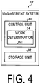
- FIG. 4 is a schematic block diagram of the management system.
- the management system 12 is a system that manages the flow of goods in the facility W.
- the management system 12 is a Warehouse Management System (WMS) in the present embodiment.
- WMS Warehouse Management System
- the management system 12 may be any system not limited to the WMS, and may be a back-end system such as other production management systems.
- the management system 12 is provided at any position.
- the management system 12 may be provided in the facility W, or may be provided at a position away from the facility W to manage the facility W therefrom.
- the management system 12 is a computer, and as illustrated in FIG. 3 , includes a control unit 30 and a storage unit 32.
- the storage unit 32 is a memory for storing various types of information such as the details of computations and programs of the control unit 30, and includes at least one of a Random Access Memory (RAM), a main storage device such as a Read Only Memory (ROM), and an external storage device such as a Hard Disk Drive (HDD).
- RAM Random Access Memory
- ROM Read Only Memory
- HDD Hard Disk Drive
- the control unit 30 is the computation device, that is, a Central Processing Unit (CPU).
- the control unit 30 includes a work determination unit 34.
- the control unit 30 implements the work determination unit 34 by reading and executing a program (software) from the storage unit 32, and executes the processing.
- the control unit 30 may execute the processing by one CPU, or may include a plurality of CPUs and execute the processing by the plurality of CPUs.
- the work determination unit 34 may be achieved by a hardware circuit.
- the work determination unit 34 determines each pallet P to be transported. Specifically, the work determination unit 34 determines the work details indicating the information on the pallet P to be transported, based on, for example, the input work plan. The work details are also considered to be information for identifying the pallet P to be transported. In the example of the present embodiment, the work determination unit 34 determines, as the work details, which pallet P (load) in which facility is to be transported, by when the pallet is to be transported and to where the pallet is to be transported. That is, the work details are information indicating the facility in which the target pallet P is stored, the target pallet P, the transport destination of the pallet P, and the time for transporting the pallet P. The work determination unit 34 transmits the determined work details to the computation device 14.
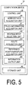
- FIG. 5 is a schematic block diagram of the computation device.
- the computation device 14 is a device that is provided in the facility W, computes information on the movement of the movable body 10, or the like, and outputs the information to the movable body 10. Further, the computation device 14 communicates with the truck V, and acquires information on the truck V that is stopped in the area Ar of the facility W.
- the information on the truck V includes information on whether to perform work in the facility W, and information on the type, position, or the like of each pallet P mounted on the truck V or each pallet P to be mounted on the truck V in the facility W.
- the computation device 14 is a computer, and as illustrated in FIG. 4 , includes a control unit 40 and a storage unit 42.
- the storage unit 42 is a memory for storing various types of information such as the details of computations and programs of the control unit 40, and includes at least one of a RAM, a main storage device such as a ROM, and an external storage device such as a HDD.
- the control unit 40 is a computation device, that is, a CPU.
- the control unit 40 includes a work details acquisition unit 50, a truck information acquisition unit 51, a movable body selection unit 52, a route acquisition unit 54, a reference position/posture acquisition unit 56, and an information output unit 60.
- the control unit 40 implements the work details acquisition unit 50, the movable body selection unit 52, the route acquisition unit 54, the information output unit 60, and the exclusive control unit 58, by reading and executing a program (software) from the storage unit 42, and executes the processing.
- the control unit 40 may execute the processing by one CPU, or may include a plurality of CPUs and execute the processing by the plurality of CPUs.
- At least a part of the work details acquisition unit 50, the truck information acquisition unit 51, the movable body selection unit 52, the route acquisition unit 54, the reference position/posture acquisition unit 56, and the information output unit 60 may be achieved by a hardware circuit.
- the work details acquisition unit 50 acquires information on the work details determined by the management system 12, that is, information on each pallet P to be transported.
- the work details acquisition unit 50 identifies the pallet P to be unloaded from the truck V, based on the information on the pallet P in the work details, and identifies the place where the pallet P is provided, and the place to which the pallet P is to be transported.
- the storage unit 42 stores information on the pallet P, the truck V, and the standby place in association with each other, and the work details acquisition unit 50 reads the information from the storage unit 42 to identify the work details.
- the movable body selection unit 52 selects the target movable body 10.
- the truck information acquisition unit 51 communicates with the truck V to be stopped in the facility W, and acquires information from the truck V.
- the movable body selection unit 52 selects a target movable body 10 from the plurality of movable bodies belonging to the facility W, for example.
- the movable body selection unit 52 may select the target movable body 10 by using any method, but may select, as the target movable body 10, for example, the movable body 10 suitable for transporting the pallet P, based on the place of the pallet P identified by the work details acquisition unit 50 or the type of the truck V.
- the route acquisition unit 54 acquires information on the route R to the area Ar identified by the work details acquisition unit 50.
- the route acquisition unit 54 acquires information on the route R associated with each pallet P to be loaded or unloaded on or from the truck V.
- the route acquisition unit 54 also acquires information obtained by recalculating the route R, based on information from the reference position/posture acquisition unit 56.
- the route acquisition unit 54 may acquire the route information from the management system 12 or may execute computing processing to acquire the route information.
- the first route R is preset, for example, for each area Ar, and, for example, the route acquisition unit 54 acquires, from the storage unit 42, position (coordinate) information on the route R set for the area Ar identified by the work details acquisition unit 50.
- the initial route R is set, for example, based on the position of the pallet P when the truck V is stopped in the set position in the area Ar.
- the route R is a path from the preset start position to the area Ar in the present embodiment.
- the start position may be a position in which the movable body 10 is on standby.
- the route R is set in advance, based on map information on the facility W.
- the map information on the facility W is information including position information on an obstacle (such as a post) installed in the facility W or a passage through which the movable body 10 is capable of traveling. It can be said that the map information is information indicating an area in which the movable body 10 is movable in the area Ar.
- the route R may be set based on vehicle specification information of the movable body 10.
- the vehicle specification information is, for example, a specification which affects the movable path of the movable body 10, such as the size and the minimum turn radius of the movable body 10.
- the route R may be set for each movable body.
- the route R may be manually set, based on the map information, the vehicle specification information, or the like, or may be automatically set by a device such as the computation device 14, based on the map information, the vehicle specification information, or the like.
- a desired pass point (Way point) may be designated.
- a shortest route R which avoids obstacles (such as a fixed object such as a wall) can be set while passing through the desired pass point.
- the reference position/posture acquisition unit 56 acquires information for identifying the position in the truck V of the first pallet P to be transported from or to the truck V, that is, the pallet P to be first unloaded from the truck V or the pallet P to be first loaded on the truck V.
- the reference position/posture acquisition unit 56 acquires, from the movable body 10, position information on the first pallet P to be transported to the truck V.
- the position information on the pallet P in the truck V includes at least the position of the pallet P, and the horizontal orientation of the pallet P within the facility W.
- the position information on the pallet P in the truck V may include the height information on the pallet P.
- the information output unit 60 outputs the information acquired by the computation device 14 to the movable body 10 via a communication unit.
- the communication method between the movable body 10 and the computation device 14 is wireless communication in the present embodiment, but any communication method may be used.
- the information output unit 60 outputs the information on the route R acquired by the route acquisition unit 54 to the movable body 10. Because the route R is a path toward the truck V, it can be considered to be information regarding the movement of the movable body 10.
- the movement control system 1 When transporting the pallets P to the truck V, the movement control system 1 acquires information on the first pallet P to be transported to the truck V, with the support of a worker. Then, the movement control system 1 sets the transport routes R for the second and subsequent pallets P, based on the acquired information on the first pallet P, and transports the pallets P by the movable body 10.
- the processing performed by the movement control system 1 will be described by describing processing by the truck, processing by the computation device, and processing by the movable body.
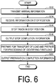
- FIG. 6 is a flowchart illustrating an example of processing performed by the truck.
- the processing illustrated in FIG. 6 is performed by a worker of the truck using various devices.
- the truck V outputs arrival information to the computation device 14 (step S12). Specifically, the truck V outputs information on a time to arrive at the facility W, and current position information. Note that when a schedule for arriving at the facility W, or the like is predetermined, the processing of step S12 may not be executed.
- the truck V receives information on a stop position (step S14).
- the truck V acquires, from the computation device 14, information on which position of the facility W the truck V is to stop.
- the truck V is stopped in the stop position (step S16).
- the worker stops the truck V in the designated area Ar.
- the truck V is stopped in the area Ar, and then outputs a position where the vehicle has been completely stopped to the computation device 14 (step S18).
- the truck V prepares for transport of a pallet (load) and prepares for processing of identifying the first load (step S20). Specifically, in preparation for the transport of the pallet (load), the worker opens the side door VB to allow the pallets P to be carried out. Further, in preparation for the processing of identifying the first load, the worker makes it possible to notify the sensor 26 of the movable body 10 of the position of the pallet P to be carried out first.
- FIG. 7 is a schematic view illustrating an example of a position identifying device.
- the worker of the present embodiment disposes a position identifying device 102 in the vicinity of the loading platform on which the pallets P are installed.
- the position identifying device 102 is a mark detectable by the sensor 26.
- the position identifying device 102 is a mark formed of a material that reflects measurement light from the sensor 26.
- the position identifying device 102 is formed in a two-dimensional pattern. By the sensor 26 detecting the position identifying device 102 of a two-dimensional pattern, the position and posture (orientation) of the pallet P associated with the position identifying device 102 can be detected.
- a unit that makes it possible to notify the sensor 26 of the movable body 10 of the position of the pallet P to be carried out first is not limited to the position identifying device 102.
- a position identifying device 104 that can be gripped by a worker may be used.
- the position identifying device 104 is a portable mark that can be detected by the sensor 26.
- the worker carries the position identifying device 104 and teaches the sensor 26 of the movable body 10 in the vicinity of the pallet P, which allows the position of the pallet P to be provided to the movable body 10. Recognition processing in the movable body 10 will be described later.
- the truck V outputs preparation completion information to the computation device 14 (step S22).
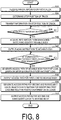
- FIG. 8 is a flowchart illustrating an example of the processing performed by the computation device.
- the computation device 14 acquires arrival information from the truck (step S32).
- the computation device 14 determines a truck stop position (step S34), and outputs information on the truck stop position to the truck (step S36).
- the computation device 14 determines whether the truck stop information has been acquired (step S38).
- the computation device 14 determines whether information indicating that the truck to which the stop position information has been provided has stopped in the designated position has been received.
- the processing returns to step S38. In other words, the computation device 14 repeats the processing in step S38 until the truck stop information is acquired.
- the computation device 14 determines that the truck stop information has been acquired (Yes in step S38)
- the computation device 14 acquires information from the management system and identifies a movable body (step S40). That is, a movable body carrying out the pallet P from the truck V is identified.
- the computation device 14 outputs a work instruction to the identified movable body (step S42).
- the work instruction includes information on a route for moving the movable body 10 that carries out the first pallet to the vicinity of the first pallet P in the area Ar, and an instruction to execute processing of detecting the position of the first pallet P.
- the computation device 14 determines whether the information for identifying the position of the first load (pallet) has been acquired from the movable body (step S44).
- the processing returns to step S44. In other words, the computation device 14 repeats the processing in step S44 until information for identifying the position of the first load (pallet) is acquired.
- the computation device 14 determines that the information for identifying the position of the first load (pallet) has been acquired (Yes in step S44), the computation device 14 generates an access path of the movable body for the first load, based on the information for identifying the first load (pallet)(step S46). That is, the computation device 14 generates a route along which the movable body 10 moves from the current position to the first pallet, based on the position information on the first pallet acquired by the movable body 10. Upon setting the access path, the computation device 14 outputs the access path to the first load (pallet) to the movable body (step S48).
- the computation device 14 generates the access paths for the second and subsequent loads, based on the information for identifying the first load (pallet) and the relative position information on the loads (pallets) (step S50). That is, the position of each pallet mounted on the truck V is calculated, based on the position information on the first pallet and the relative position information on each pallet mounted on the truck V, and the route along which the movable body 10 makes access is generated, based on the position of each pallet.
- the relative position information on each pallet can be acquired based on the information on the loading platform of the truck, the position of each pallet mounted, and the like, included in the information transmitted from the truck. Specifically, the computation device 14 acquires the position and posture of the first pallet.
- the computation device 14 estimates the placement position of each pallet in the truck, for example, based on the number of the pallets mounted on the truck V obtained from the relative position information on the pallets and based on the information on the placement interval (for example, information on the thickness of a buffer material disposed between the pallets).
- the computation device 14 generates access paths for the second and subsequent pallets, based on the estimated position information and posture information of the second and subsequent pallets.
- the computation device 14 may also acquire position information on the second and subsequent pallets, perform the same processing as in steps S46 to S50, based on the acquired position information on the plurality of pallets, and regenerate (modify) access paths for the acquired transport target pallet and pallets subsequent thereto.
- the computation device 14 Upon generating the access paths, the computation device 14 outputs the access paths for the second and subsequent loads (pallets) to the movable body (step S52). When the plurality of pallets P mounted on the one truck V are transported by the plurality of movable bodies 10, the computation device 14 outputs respective access paths to the movable bodies 10.
- FIG. 9 is a flowchart illustrating an example of processing performed by the movable body.
- the movable body 10 acquires work information transmitted from the computation device 14 (step S62).
- the movable body 10 determines whether the information is for processing for the first load (pallet) (step S64).
- the movable body 10 may execute the processing in steps S64 to S80 by executing the processing included in the work information without executing the determination processing. In other words, the movable body 10 may perform the processing based on the work information and perform each of the processing operations in FIG. 9 .
- step S64 When the movable body 10 determines that the information is not for the processing for the first load (pallet) (No in step S64), the processing proceeds to step S76.
- step S76 When determining that the information is for the processing for the first load (pallet) (Yes in step S64), the movable body 10 moves to the vicinity of the target truck, based on the current access route (step S66).
- the movable body 10 acquires information on an identification position, which is information for identifying the position of the first load (step S68). Specifically, as described above, the sensor 26 detects the position identifying device disposed by the worker in the vicinity of the first pallet. The position of the position identifying device detected by the sensor 26 is set as an identification position for identifying the first pallet.
- the movable body 10 After detecting the identification position of the pallet, the movable body 10 outputs the identification position of the first load (pallet) to the computation device 14 (step S70). After outputting the identification position, the movable body 10 acquires the access path for the first load (pallet) (step S72). In other words, the route of movement from the current position to the pallet P, calculated based on the identification position by the computation device 14, is acquired. The movable body 10 moves based on the access path, and transports the load (pallet) (step S74).
- the movable body 10 After executing the processing in step S74 or when making a determination of No in step S64, the movable body 10 acquires information on the access path for the target load (step S76). That is, the movable body 10 acquires information on the access paths for transporting the second and subsequent pallets and the route for moving to the target pallet. The movable body 10 moves based on the acquired access path, and transports each load (pallet) (step S78).
- the movable body 10 when approaching each of the second and subsequent pallets, measures the position of the pallet during the approach, and acquires deviation information between the estimated pallet position and the measured pallet position.
- the pallets mounted on the truck may positionally deviated due to deviation when the pallets are mounted or variation in the thicknesses of buffer materials.
- the movable body 10 allows the fork to perform side-shift (move the position of the fork in the horizontal direction) and hold the pallet.
- the movable body 10 outputs information on the positional deviation of the pallet and the amount of side-shift to the computation device 14.
- the movable body 10 may use a method for updating and correcting an approach path, based on the positional deviation, or a method of correcting the positional deviation by using a servomechanism.
- the computation device 14 may regenerate or slightly modify the access routes, based on the acquired information on the transport of the second and subsequent pallets. Consequently, the influence due to the size variation of the buffer materials, the size variation of the pallets, and the load overhang on the pallet can be flexibly dealt with.
- the movable body 10 determines whether the processing has ended, that is, whether the transport of the pallets has ended (step S80). When the movable body 10 determines that the processing has not ended (No in step S80), the processing returns to step S76 and the processing of transporting another pallet P is performed. When the movable body 10 determines that the processing has ended (Yes in step S80), the present processing ends.
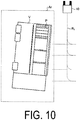
- FIG. 10 is an explanatory diagram for describing processing performed by the movement control system.
- FIG. 11 is an explanatory diagram for describing processing performed by the movement control system.
- FIG. 12 is an explanatory diagram for describing processing performed by the movement control system.
- the movement control system 1 performs the processing in FIGS. 6 , 8 , and 9 in conjunction with the truck V, the computation device 14, and the movable body 10, thereby transporting pallets (loads) which are target objects.
- the movement control system 1 sets a standard access route R1 for the movable body 10 to the area Ar in which the truck V is stopped.
- the access route R1 is a route set in assumption that the truck V is stopped in the standard position in the area Ar.
- the truck V may not stop in the center of the area Ar, and may deviate from the presumed position.
- the movable body 10 moves along the route R1 in this deviated state, it takes a long time to find the first pallet P. It is also possible to mistakenly recognize another pallet. Further, the calculation load also increases when the plurality of pallets P are detected each time.
- the movable body 10 is moved to the vicinity of the truck V, based on the route R1 when the first pallet P is picked up. Thereafter, the movable body 10 detects the position identifying devices 102, 104 that the worker has arranged such that they are capable of being recognized by the movable body 10, thereby detecting the position of the first pallet.
- the movement control system 1 calculates a route R2 to the position of the first pallet, based on the detected results, and moves the movable body 10 as illustrated in step S94. This allows the movable body 10 to move to a position where it is easy to pick up the first pallet.
- the processing of picking up each pallet with the movable body 10 will be described below using FIG. 12 .
- the movable body 10 moves from a position away from the pallet P as illustrated in step S102 to the vicinity of the pallet P as illustrated in step S104.
- the movable body 10 moves the fork 24 in the vertical direction to the hold position of the pallet P, as illustrated in step S108.
- the movable body 10 extends the fork 24 in the horizontal direction and inserts the tip of the fork 24 into the insertion position of the pallet P, as illustrated in step S110.
- the movable body 10 moves the fork 24 vertically upward with the fork 24 inserted into the pallet P and retracts the fork 24 to hold the pallet P with the fork 24, as illustrated in step S112.
- the movable body 10 then retracts the fork 24 to hold the pallet P at the base portion of the fork 24, as illustrated in step S114.
- the movable body 10 itself may move in the front-back direction without extending and retracting the fork 24 to bring the positional relationship between the fork 24 and the pallet to the above state.
- the movement control system 1 calculates access routes R3 to other pallets, based on the position information on the first pallet P and the information on the relative position of the other pallets in the truck V, which are detected during transport of the first pallet P. Thus, as illustrated in step S96 in FIG. 11 , the access routes R3 whose positions are adjusted according to the posture of the truck V is calculated. The movement control system 1 moves the movable body 10, based on the calculated access routes R3.
- the movement control system 1 can move the movable body 10 with high accuracy to the pallets mounted on the truck, which is the target area, by calculating the access routes for the second and subsequent pallets, based on the position information on the first pallet. Further, during transport of the first pallet, the position information on the first pallet is detected based on the assistance of the worker, and the second and subsequent pallets can be automatically transported. Thus, the burden on the worker can be reduced and the accuracy of access to the pallets can be increased. According to the movement control system 1, it is also possible to improve throughput by increasing the speed of access to the pallets.
- the movement control system 1 can identify the position by detecting the position identifying devices 102, 104 by the sensor 26, it is possible to reduce an increase in a work burden on the worker. Further, it is preferable that in the movement control system 1, the movable body 10 be provided with a mechanism for sliding the fork 24 and a mechanism for tilting the fork 24 so that the position of the fork 24 holding the pallet P is finely adjusted. This can increase the allowable deviation amount of the information for identifying the position information on the first pallet using the position identifying devices 102, 104, and thus increase the workability.
- the movement control system 1 can finely adjust the position of the fork 24 holding each pallet P, even when the positions of the second and subsequent pallets are deviated. Thus, it is possible to absorb the positional deviation due to the size variation of the pallets, the size variation of the buffer materials, and the overhang of the load on the pallet, and further increase the flexibility and improve the operating ratio.
- each pallet, which is the target object is picked up from the truck, which is the target area
- the present disclosure can also be used in cases where each pallet, which is the target object, is dropped into the truck, which is the target area.
- the movable body 10 drops the target objects
- the position of each pallet P in the target area is detected
- the positions where the second and subsequent pallets are dropped are determined by using the result, and the access route is calculated.
- the movement control system 1 detects the environment on both sides of the pallet drop position. For example, in the case of the first pallet, the positions of columns or walls of the loading platform of the truck is grasped.
- the movement control system 1 estimates the position of an adjacent pallet load and the position of a buffer material and sets an access route. In the case of the last pallet, the movement control system 1 sets an access route on the basis of the load of the adjacent pallet and the information on the columns or walls of the loading platform. It is also preferable that the movable body move based on the information on the access route, and that the movable body drop the load while performing fine modification by the side shifting mechanism when finally dropping the load.
- FIG. 13 is an explanatory diagram for describing processing for dropping a target object in the movement control system.
- FIG. 14 is an explanatory diagram for describing processing for dropping a target object in the movement control system.
- the movement control system 1 moves the movable body 10 holding the pallet P to be dropped, to the vicinity of the truck V to which the first pallet P is to be dropped, based on a route R4.
- the route R4 is the route when the truck V is stopped in an ideal position in the area.
- the movable body 10 detects the position identifying devices 102, 104 that the worker has arranged such that they are capable of being recognized by the movable body 10, thereby detecting the position where the first pallet is to be dropped.
- the movement control system 1 calculates a route R5 to the position where the first pallet is to be dropped, based on the detected results, and moves the movable body 10 as illustrated in step S134. This allows the movable body 10 to move to a position where it is easy to drop the first pallet.
- the processing of dropping each pallet with the movable body 10 will be described below using FIG. 14 .
- the movable body 10 moves from a position away from a drop position as illustrated in step S142 to the vicinity of a position in the truck V where the pallet P is to be dropped as illustrated in step S144.
- the movable body 10 moves the fork 24 in the vertical direction to the hold position of the pallet P, as illustrated in step S146.
- the movable body 10 extends the fork 24 in the horizontal direction, and moves the pallet P to immediately above the position in the truck V where the pallet P is to be dropped, as illustrated in step S148.
- the movable body 10 moves the fork 24 vertically downward with the fork 24 inserted into the pallet P to bring the pallet P into contact with the truck V, as illustrated in step S150. Thereafter, the fork 24 is retracted to leave the movable body 10 away from the pallet P, as illustrated in step S152.
- the movement control system 1 calculates access routes R6 to other pallets, based on the position information on the first pallet P and the information on the relative position of the other pallets in the truck V, which are detected during transport of the first pallet P. Thus, as illustrated in step S136 in FIG. 13 , the access routes R6 whose positions are adjusted according to the posture of the truck V is calculated. The movement control system 1 moves the movable body 10 based on the calculated access routes R6 to drop the pallets P at respective positions of the truck V.
- the movement control system 1 can identify the drop position of the first pallet while obtaining the support of the worker, determine the drop positions of the second and subsequent pallets by using the result, and transport the pallets in an automatic operation, thereby transporting the target objects efficiently with high accuracy.
- FIG. 15 is a schematic view illustrating an overview of a movement control system according to another embodiment.
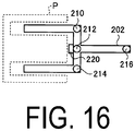
- FIG. 16 is a schematic view illustrating an example of a position identifying device.
- the movement control system illustrated in FIG. 15 includes cameras 150, 152.
- the movement control system detects the position of a position identifying device 202 with the cameras 150, 152.
- the position identifying device 202 includes a tip portion corresponding to the tip of the fork 24, and a gripping portion held by the worker.
- the position identifying device 202 includes marks 210, 212, 214, and 216 on the externally exposed portion with the tip portion inserted into the pallet P.
- a switch 220 is disposed in a position that contacts the pallet P.
- the worker inserts the position identifying device 202 into the first pallet P and brings the switch 220 and pallet P into contact.
- the marks 210, 212, 214 and 216 of the position identifying device 202 are detected by the cameras 150, 152.
- the method for detecting the marks is not limited thereto.
- a laser sensor may detect the position of the object.
- Position information on the detected marks 210, 212, 214, and 216 is detected as information for identifying the position of the first pallet P.
- the movement control system 1 calculates the position of the pallet P and determines an access route, by analyzing the image information in which the marks 210, 212, 214, and 216 are captured.
- the position of the pallet P may be calculated by capturing the position identifying device 202 associated with the first pallet P by the camera disposed in the facility W. Further, by using the position identifying device 202, the position where the fork 24 is disposed when the pallet P is held can be detected with high accuracy. Thus, the position detection accuracy can be further improved. Note that the switch 220 may not be required.
- the position identifying device is detected, and, based on the result, the information for identifying the position of the first pallet is acquired, but the method of acquiring the information for identifying the location of the first pallet is not limited thereto.
- the position of the first pallet may be detected based on information when the worker controls the operation of the movable body 10 to actually move the pallet.
- FIG. 17 is a flowchart illustrating another example of the processing performed by the computation device.
- FIG. 18 is a flowchart illustrating another example of the processing performed by the movable body.
- the computation device 14 acquires arrival information from the truck (step S32).
- the computation device 14 determines a truck stop position (step S34), and outputs information on the truck stop position to the truck (step S36).
- the computation device 14 determines whether the truck stop information has been acquired (step S38).
- the computation device 14 determines whether information indicating that the truck to which the stop position information has been provided has stopped in the designated position has been received.
- the processing returns to step S38. In other words, the computation device 14 repeats the processing in step S38 until the truck stop information is acquired.
- the computation device 14 determines that the truck stop information has been acquired (Yes in step S38)
- the computation device 14 acquires information from the management system and identifies a movable body (step S40). That is, a movable body carrying out the pallet P from the truck V is identified.
- the computation device 14 outputs a work instruction to the identified movable body (step S42).
- the work instruction includes information on the route for moving the movable body 10 that carries out the first pallet to the vicinity of the first pallet P in the area Ar, and an instruction to execute processing of detecting the position of the first pallet P.
- the computation device 14 determines whether information on the transport route has been acquired from the movable body as information for identifying the position of the first load (pallet) (step S202). When the computation device 14 determines that the information for identifying the position of the first load (pallet) has not been acquired (No in step S202), the processing returns to step S202. In other words, the computation device 14 repeats the processing in step S202 until the information for identifying the position of the first load (pallet) is acquired.
- the computation device 14 When it is determined that the information for identifying the position of the first load (pallet) has been acquired (Yes in step S202), the computation device 14 generates access paths for the second and subsequent loads, based on the information for identifying the first load (pallet) and relative position information on the loads (pallets) (step S50).
- the position of each pallet mounted on the truck V is calculated, based on the position information on the first pallet and the relative position information on each pallet mounted on the truck V, and the route along which the movable body 10 makes access is generated, based on the position of each pallet.
- the relative position information on each pallet can be acquired based on the information on the loading platform of the truck, the position of each pallet mounted, and the like, included in the information transmitted from the truck.
- the computation device 14 Upon generating the access paths, the computation device 14 outputs the access paths for the second and subsequent loads (pallets) to the movable body (step S52).
- the computation device 14 outputs respective access paths to the movable bodies 10.
- FIG. 18 is a flowchart illustrating another example of the processing performed by the movable body.
- the movable body 10 acquires work information transmitted from the computation device 14 (step S62).
- the movable body 10 determines whether the information is for processing for the first load (pallet) (step S64).
- the movable body 10 may execute the processing in steps S64 to S80 by executing the processing included in the work information without executing the determination processing. In other words, the movable body 10 may perform the processing based on the work information and perform each of the processing operations in FIG. 9 .
- the processing proceeds to step S76.
- the movable body 10 transports the first load (pallet) based on a control instruction (step S222).
- the control instruction is input by the worker.
- an input may be performed by a remote operation using a remote controller, or may be performed by operating the operation unit of the movable body 10.
- the remote controller is used, the remote operation may be performed while the site is checked using the monitor, or may be performed while the movable body 10 and the pallet are viewed on-site.
- the movable body 10 outputs, to the computation device, the information on the route for transporting the first load (pallet) as information on an identification position which is information for identifying the position of each pallet (step S224).
- the movable body 10 After executing the processing in step S224 or when making a determination of No in step S64, the movable body 10 acquires information on the access path for the target load (step S76). That is, the movable body 10 acquires information on the access paths for transporting the second and subsequent pallets and the route for moving to the target pallet. The movable body 10 moves based on the acquired access path, and transports each load (pallet) (step S78).
- the movable body 10 determines whether the processing has ended, that is, whether the transport of the pallets has ended (step S80). When the movable body 10 determines that the processing has not ended (No in step S80), the processing returns to step S76 and the processing of transporting another pallet P is performed. When the movable body 10 determines that the processing has ended (Yes in step S80), the present processing ends.
- the movement control system 1 may perform the transport of the first pallet by the worker's operation, identify the position of the first pallet, based on the information on the operated route, and calculate the access routes for the second and subsequent pallets.
- the worker transports only the first pallet, and it is possible to automatically detect the access routes for the remaining pallets.
- the movable body 10 operated by the worker may be provided with a driver seat.
- the movement control system 1 be provided with a monitoring device, and that the movable bodies 10 other than the target movable body 10 be not approach the worker when the worker is performing auxiliary operations for identifying the position of the first pallet. This increases the safety of a work operation.
- the management system 12 determines work details indicating information on each pallet P, and the computation device 14 identifies the target movable body 10, and acquires the route R.
- the processing details of the management system 12 and the computation device 14 are not limited thereto.
- the management system 12 may perform at least some of the processing of the computation device 14 instead, or the computation device 14 may perform at least some of the processing of the management system 12 instead.
- the management system 12 and the computation device 14 may be configured as one device (computer).
- the embodiment of the present invention is described above, but the embodiment is not limited by the embodiment above.
- the constituent elements of the above-described embodiment include elements that are able to be easily conceived by a person skilled in the art, and elements that are substantially the same, that is, elements of an equivalent scope.
- the constituent elements described above can be appropriately combined. Further, it is possible to make various omissions, substitutions, and changes to the constituent elements within a range not departing from the scope of the above-described embodiment.
- the target area is a vehicle such as a truck, but it is only required that the target objects (loads) be regularly arranged (aligned) within a predetermined range.
- the present disclosure can also be applied in cases where the target object is disposed in the area where a partition is provided.
Landscapes
- Engineering & Computer Science (AREA)
- Structural Engineering (AREA)
- Transportation (AREA)
- Physics & Mathematics (AREA)
- Automation & Control Theory (AREA)
- General Physics & Mathematics (AREA)
- Aviation & Aerospace Engineering (AREA)
- Radar, Positioning & Navigation (AREA)
- Remote Sensing (AREA)
- Life Sciences & Earth Sciences (AREA)
- Geology (AREA)
- Mechanical Engineering (AREA)
- Civil Engineering (AREA)
- Electromagnetism (AREA)
- Combustion & Propulsion (AREA)
- Chemical & Material Sciences (AREA)
- Computer Vision & Pattern Recognition (AREA)
- Multimedia (AREA)
- Optics & Photonics (AREA)
- Warehouses Or Storage Devices (AREA)
- Control Of Position, Course, Altitude, Or Attitude Of Moving Bodies (AREA)
Abstract
Description
- The present invention relates to a control device, a movement control system, a control method, and a program.
- In a movable body such as a forklift that transports a load, a technology has been known that detects the position of a load that is an object to be transported and automatically picks up and moves the load to a target position. In Patent Literature 1, a control device is described which detects a label attached to a load, identifies the position of the load, and controls the position of a movable body to pick up the load.
- Patent Literature 1:
JP 2003-212489 A - Here, an object such as a load may be placed in a position deviated from a presumed installation position. Further, when an object is transported to a truck or the like, and the stop position of the truck deviates from a presumed position, the object cannot be transported to a presumed position in the truck. In the method described in Patent Literature 1, the correct position can be detected by detecting a marker of the object, but processing of detecting the marker is executed every time, so that there is a limit to the improvement of work efficiency.
- The present disclosure is intended to solve the above-described problems, and an object of the present disclosure is to provide a control device, a movement control system, a control method, and a program capable of transporting an object efficiently with high accuracy.
- To solve the problems described above and achieve an object, a control device according to the present disclosure is a computation device for outputting information to a movable body configured to move automatically, the control device including a route acquisition unit configured to acquire a route of the movable body for moving a plurality of aligned target objects to or from a target position at which the target objects are picked up or dropped; a reference position/posture acquisition unit configured to acquire information on a position at which the movable body picks up or drops a first target object of the plurality of target objects at the target position; and an information output unit configured to output the information acquired by the route acquisition unit to the movable body, in which the route acquisition unit acquires routes of the movable body for moving second and subsequent target objects of the plurality of target objects, based on the information acquired by the reference position/posture acquisition unit.
- To solve the problems described above and achieve the object, a movement control system according to the present disclosure includes the computation device and the movable body.
- To solve the problems described above and achieve an object, a control method according to the present disclosure is a control method of a movable body configured to transport a plurality of aligned target objects to or from a target position, the control method comprising: acquiring information on a position for picking up or dropping a first target object of the plurality of target objects at the target position; acquiring routes of the movable body for moving second and subsequent target objects of the plurality of target objects, based on the information on the position for picking up or dropping the first target object; and outputting the acquired routes of the movable body.
- To solve the problems described above and achieve an object, a program according to the present disclosure is a program for causing a computer to execute a control method of a movable body configured to transport a plurality of aligned target objects to or from a target position, the program causing the computer to execute: acquiring information on a position for picking up or dropping a first target object of the plurality of target objects at the target position; acquiring routes of the movable body for moving second and subsequent target objects of the plurality of target objects, based on the information on the position for picking up or dropping the first target object; and outputting the acquired routes of the movable body.
- According to the present disclosure, objects can be transported efficiently with high accuracy.
-
-
FIG. 1 is a schematic view of a movement control system according to the present embodiment. -
FIG. 2 is a schematic view illustrating a schematic configuration of a truck. -
FIG. 3 is a schematic view of a configuration of a movable body. -
FIG. 4 is a schematic block diagram of a management system. -
FIG. 5 is a schematic block diagram of a computation device. -
FIG. 6 is a flowchart illustrating an example of processing performed by the truck. -
FIG. 7 is a schematic view illustrating an example of a position identifying device. -
FIG. 8 is a flowchart illustrating an example of processing performed by the computation device. -
FIG. 9 is a flowchart illustrating an example of processing performed by the movable body. -
FIG. 10 is an explanatory diagram for describing processing performed by the movement control system. -
FIG. 11 is an explanatory diagram for describing processing performed by the movement control system. -
FIG. 12 is an explanatory diagram for describing processing performed by the movement control system. -
FIG. 13 is an explanatory diagram for describing processing for dropping a target object in the movement control system. -
FIG. 14 is an explanatory diagram for describing processing for dropping a target object in the movement control system. -
FIG. 15 is a schematic view illustrating a movement control system according to another embodiment. -
FIG. 16 is a schematic view illustrating an example of a position identifying device. -
FIG. 17 is a flowchart illustrating another example of the processing performed by the computation device. -
FIG. 18 is a flowchart illustrating another example of the processing performed by the movable body. - Preferred embodiments of the present invention will be described in detail below with reference to the accompanying drawings. Note that the present invention is not limited to these embodiments, and, when there are a plurality of embodiments, the present invention is intended to include a configuration combining these embodiments.
-
FIG. 1 is a schematic view of a movement control system according to a first embodiment. As illustrated inFIG. 1 , a movement control system 1 according to the first embodiment includes amovable body 10, amanagement system 12, and acomputation device 14. The movement control system 1 is a system that controls movement of themovable body 10 that belongs to a facility W. The facility W is a facility that is logistically managed, such as a warehouse. In the facility W of the present embodiment, a truck V is stopped in an area Ar. The movement control system 1 picks up a pallet (load) P mounted on the truck (vehicle) V with themovable body 10, and drops the pallet P in a predetermined standby position. The movement control system 1 also picks up a pallet P disposed in a predetermined standby position with themovable body 10, and drops the pallet P in the truck V. In other words, the movement control system 1 performs unloading work or loading work of the pallet P from or on the truck V. The area Ar is an area which is set as a stop position of the truck V, and is divided by, for example, a white line or the like. An area where themovable body 10 moves is provided around the area Ar. The standby place can be provided at any place of the facility W. Further, although only one area Ar is illustrated in the facility W of the present embodiment, a plurality of the areas Ar may be disposed. Further, the number of themovable bodies 10 is not limited to two, and may be one or three or more. -
FIG. 2 is a schematic view illustrating a schematic configuration of the truck. The truck V of the present embodiment is a vehicle that travels by driving a plurality of tires VE. The truck V is a vehicle on which a plurality of pallets P can be mounted. In the truck V illustrated inFIG. 1 , four pallets P are arranged in two rows. The pallets P are mounted in the storage chamber VA of the truck V, as illustrated inFIG. 2 . The truck V includes a side door VB. The side door VB is a door provided on each side of the storage chamber VA. The side door VB of the truck V is opened to allow the storage chamber VA to communicate with the exterior, so that the pallets P can be carried out. The truck V of the present embodiment includes a position in the storage chamber VA where the pallets P are held. The plurality of pallets P are arranged side-by-side within the storage chamber VA of the truck V. In the truck V of the present embodiment, the pallets are arranged in two rows in the storage chamber VA. Note that there are various arrangement patterns such as a case where the pallets are placed without intervals therebetween on the front side of the truck, a case where the pallets are placed without intervals therebetween on the rear side, or a case where the pallets placed in the storage chamber VA at intervals. The truck V of the present embodiment includes the side doors VB on both sides, and themovable body 10 can access the pallets P from each of the two side. The truck V of the present embodiment has a structure in which each side door VB is a rigid body and opens and closes vertically, but the side door VB may also be a curtain type door formed of a deforming fabric or plastic which opens and closes by moving its one end horizontally. - The
movable body 10 is an automatically movable device. In the present embodiment, themovable body 10 is a forklift, so called an Automated Guided Forklift (AGF) or Automated Guided Vehicle (AGV). Themovable body 10 moves within the facility W. Themovable body 10 moves to the vicinity of the truck V, for example, along a route R. The route R is information transmitted from thecomputation device 14. When themovable body 10 has reached the vicinity of the vehicle V, themovable body 10 moves based on the set route and picks up each pallet P, based on the position information on the pallet P. The route R will be described in detail below. Hereinafter, one horizontal direction is referred to as a direction X, and a direction orthogonal to the direction X in the horizontal direction is referred to as a direction Y. Further, the direction orthogonal to the horizontal direction, that is, the direction orthogonal to the directions X and Y, is referred to as a direction Z. -
FIG. 3 is a schematic view of a configuration of the movable body. As illustrated inFIG. 3 , themovable body 10 includes avehicle body 20, amast 22, afork 24, asensor 26, and acontrol device 28. Thevehicle body 20 includes awheel 20A. Themast 22 is provided at one end portion in the front-back direction of thevehicle body 20. Themast 22 extends along a vertical direction (here, the direction Z) orthogonal to the front-back direction. Thefork 24 is attached to themast 22 in a manner movable in the direction Z. Thefork 24 may be movable with respect to themast 22 in the lateral direction of the vehicle body 20 (the direction intersecting the vertical direction and the front-back direction). Thefork 24 includes a pair oftabs tabs mast 22 toward the front direction of thevehicle body 20. Thetabs mast 22. In the front-back direction, the direction where thefork 24 is provided in themovable body 10 is referred to as a first direction, and the direction where thefork 24 is not provided is referred to as a second direction. - The
sensor 26 detects at least one of the position and orientation of an object present around thevehicle body 20. Thesensor 26 can also detect the position of the object relative to themovable body 10 and the orientation of the object relative to themovable body 10. In the present embodiment, thesensor 26 is provided in themast 22, and detects the position and orientation of an object on the first direction side of thevehicle body 20. However, the detection direction of thesensor 26 is not limited to the first direction, and for example, the detection may be performed on both of the first direction side and the second direction side. In this case, as thesensor 26, a sensor for detection on the first direction side and a sensor for detection on the second direction side may be provided. Thesensor 26 is a sensor that emits a laser beam, for example. Thesensor 26 emits a laser beam while performing a scan in one direction (here, the lateral direction), and detects the position and orientation of an object based on reflected light of the emitted laser beam. Thesensor 26 is not limited to the above, and may be a sensor for detecting a target object using any method. For example, thesensor 26 may be a camera or the like. Further, the position at which thesensor 26 is provided is not limited to themast 22. Specifically, for example, a safety sensor provided on themovable body 10 may be also used as thesensor 26. The use of the safety sensor eliminates necessity of newly installing the sensor. As thesensor 26, a sensor provided with a mechanism that moves in the direction Z (vertical direction) with respect to the fork may also be provided. Thus, by moving the sensor in the direction Z, sensing can be performed without conjunction with the motion of the mast of the forklift. - The
control device 28 controls the movement of themovable body 10. Thecontrol device 28 is a computer, and includes a control unit and a storage unit. The storage unit is a memory for storing various types of information such as the details of computations and programs of the control unit, and includes at least one of a RAM, a main storage device such as a ROM, and an external storage device such as a HDD. Thecontrol device 28 detects the position of themovable body 10, moves based on the information on the route R supplied from thecomputation device 14, and moves the pallet P. Thecontrol device 28 may also adjust the position of thefork 24 and the posture of themovable body 10, based on the detection results of the position and orientation of the pallet P from thesensor 26 of themovable body 10, and pick up and drop each pallet P. Further, thecontrol device 28 outputs information detected by thesensor 26 to thecomputation device 14. -
FIG. 4 is a schematic block diagram of the management system. Themanagement system 12 is a system that manages the flow of goods in the facility W. Themanagement system 12 is a Warehouse Management System (WMS) in the present embodiment. However, themanagement system 12 may be any system not limited to the WMS, and may be a back-end system such as other production management systems. Themanagement system 12 is provided at any position. Themanagement system 12 may be provided in the facility W, or may be provided at a position away from the facility W to manage the facility W therefrom. Themanagement system 12 is a computer, and as illustrated inFIG. 3 , includes acontrol unit 30 and astorage unit 32. Thestorage unit 32 is a memory for storing various types of information such as the details of computations and programs of thecontrol unit 30, and includes at least one of a Random Access Memory (RAM), a main storage device such as a Read Only Memory (ROM), and an external storage device such as a Hard Disk Drive (HDD). - The
control unit 30 is the computation device, that is, a Central Processing Unit (CPU). Thecontrol unit 30 includes a work determination unit 34. Thecontrol unit 30 implements the work determination unit 34 by reading and executing a program (software) from thestorage unit 32, and executes the processing. Note that thecontrol unit 30 may execute the processing by one CPU, or may include a plurality of CPUs and execute the processing by the plurality of CPUs. The work determination unit 34 may be achieved by a hardware circuit. - The work determination unit 34 determines each pallet P to be transported. Specifically, the work determination unit 34 determines the work details indicating the information on the pallet P to be transported, based on, for example, the input work plan. The work details are also considered to be information for identifying the pallet P to be transported. In the example of the present embodiment, the work determination unit 34 determines, as the work details, which pallet P (load) in which facility is to be transported, by when the pallet is to be transported and to where the pallet is to be transported. That is, the work details are information indicating the facility in which the target pallet P is stored, the target pallet P, the transport destination of the pallet P, and the time for transporting the pallet P. The work determination unit 34 transmits the determined work details to the
computation device 14. -
FIG. 5 is a schematic block diagram of the computation device. Thecomputation device 14 is a device that is provided in the facility W, computes information on the movement of themovable body 10, or the like, and outputs the information to themovable body 10. Further, thecomputation device 14 communicates with the truck V, and acquires information on the truck V that is stopped in the area Ar of the facility W. The information on the truck V includes information on whether to perform work in the facility W, and information on the type, position, or the like of each pallet P mounted on the truck V or each pallet P to be mounted on the truck V in the facility W. Thecomputation device 14 is a computer, and as illustrated inFIG. 4 , includes acontrol unit 40 and a storage unit 42. The storage unit 42 is a memory for storing various types of information such as the details of computations and programs of thecontrol unit 40, and includes at least one of a RAM, a main storage device such as a ROM, and an external storage device such as a HDD. - The
control unit 40 is a computation device, that is, a CPU. Thecontrol unit 40 includes a work detailsacquisition unit 50, a truck information acquisition unit 51, a movablebody selection unit 52, aroute acquisition unit 54, a reference position/posture acquisition unit 56, and aninformation output unit 60. Thecontrol unit 40 implements the work detailsacquisition unit 50, the movablebody selection unit 52, theroute acquisition unit 54, theinformation output unit 60, and the exclusive control unit 58, by reading and executing a program (software) from the storage unit 42, and executes the processing. Note that thecontrol unit 40 may execute the processing by one CPU, or may include a plurality of CPUs and execute the processing by the plurality of CPUs. At least a part of the work detailsacquisition unit 50, the truck information acquisition unit 51, the movablebody selection unit 52, theroute acquisition unit 54, the reference position/posture acquisition unit 56, and theinformation output unit 60 may be achieved by a hardware circuit. - The work details
acquisition unit 50 acquires information on the work details determined by themanagement system 12, that is, information on each pallet P to be transported. The work detailsacquisition unit 50 identifies the pallet P to be unloaded from the truck V, based on the information on the pallet P in the work details, and identifies the place where the pallet P is provided, and the place to which the pallet P is to be transported. For example, the storage unit 42 stores information on the pallet P, the truck V, and the standby place in association with each other, and the work detailsacquisition unit 50 reads the information from the storage unit 42 to identify the work details. The movablebody selection unit 52 selects the targetmovable body 10. The truck information acquisition unit 51 communicates with the truck V to be stopped in the facility W, and acquires information from the truck V. - The movable
body selection unit 52 selects a targetmovable body 10 from the plurality of movable bodies belonging to the facility W, for example. The movablebody selection unit 52 may select the targetmovable body 10 by using any method, but may select, as the targetmovable body 10, for example, themovable body 10 suitable for transporting the pallet P, based on the place of the pallet P identified by the work detailsacquisition unit 50 or the type of the truck V. - The
route acquisition unit 54 acquires information on the route R to the area Ar identified by the work detailsacquisition unit 50. Theroute acquisition unit 54 acquires information on the route R associated with each pallet P to be loaded or unloaded on or from the truck V. Theroute acquisition unit 54 also acquires information obtained by recalculating the route R, based on information from the reference position/posture acquisition unit 56. Theroute acquisition unit 54 may acquire the route information from themanagement system 12 or may execute computing processing to acquire the route information. The first route R is preset, for example, for each area Ar, and, for example, theroute acquisition unit 54 acquires, from the storage unit 42, position (coordinate) information on the route R set for the area Ar identified by the work detailsacquisition unit 50. The initial route R is set, for example, based on the position of the pallet P when the truck V is stopped in the set position in the area Ar. The route R is a path from the preset start position to the area Ar in the present embodiment. Here, the start position may be a position in which themovable body 10 is on standby. The route R is set in advance, based on map information on the facility W. The map information on the facility W is information including position information on an obstacle (such as a post) installed in the facility W or a passage through which themovable body 10 is capable of traveling. It can be said that the map information is information indicating an area in which themovable body 10 is movable in the area Ar. In addition to the map information on the facility W, the route R may be set based on vehicle specification information of themovable body 10. The vehicle specification information is, for example, a specification which affects the movable path of themovable body 10, such as the size and the minimum turn radius of themovable body 10. In a case where the route R is set based on the vehicle specification information, the route R may be set for each movable body. Note that the route R may be manually set, based on the map information, the vehicle specification information, or the like, or may be automatically set by a device such as thecomputation device 14, based on the map information, the vehicle specification information, or the like. When the route R is automatically set, for example, a desired pass point (Way point) may be designated. In this case, a shortest route R which avoids obstacles (such as a fixed object such as a wall) can be set while passing through the desired pass point. - The reference position/posture acquisition unit 56 acquires information for identifying the position in the truck V of the first pallet P to be transported from or to the truck V, that is, the pallet P to be first unloaded from the truck V or the pallet P to be first loaded on the truck V. The reference position/posture acquisition unit 56 acquires, from the
movable body 10, position information on the first pallet P to be transported to the truck V. The position information on the pallet P in the truck V includes at least the position of the pallet P, and the horizontal orientation of the pallet P within the facility W. The position information on the pallet P in the truck V may include the height information on the pallet P. - The
information output unit 60 outputs the information acquired by thecomputation device 14 to themovable body 10 via a communication unit. The communication method between themovable body 10 and thecomputation device 14 is wireless communication in the present embodiment, but any communication method may be used. Theinformation output unit 60 outputs the information on the route R acquired by theroute acquisition unit 54 to themovable body 10. Because the route R is a path toward the truck V, it can be considered to be information regarding the movement of themovable body 10. - Next, a processing operation by the movement control system 1 will be described using
FIGS. 6 to 12 . When transporting the pallets P to the truck V, the movement control system 1 acquires information on the first pallet P to be transported to the truck V, with the support of a worker. Then, the movement control system 1 sets the transport routes R for the second and subsequent pallets P, based on the acquired information on the first pallet P, and transports the pallets P by themovable body 10. Hereinafter, the processing performed by the movement control system 1 will be described by describing processing by the truck, processing by the computation device, and processing by the movable body. Further, in the following, a case of unloading work will be described in which themovable body 10 carries out the pallets P in the truck V from the truck V after the truck V arrives at the facility W in a state where the pallets P are mounted on the truck V. -
FIG. 6 is a flowchart illustrating an example of processing performed by the truck. The processing illustrated inFIG. 6 is performed by a worker of the truck using various devices. First, the truck V outputs arrival information to the computation device 14 (step S12). Specifically, the truck V outputs information on a time to arrive at the facility W, and current position information. Note that when a schedule for arriving at the facility W, or the like is predetermined, the processing of step S12 may not be executed. - The truck V receives information on a stop position (step S14). The truck V acquires, from the
computation device 14, information on which position of the facility W the truck V is to stop. The truck V is stopped in the stop position (step S16). The worker stops the truck V in the designated area Ar. The truck V is stopped in the area Ar, and then outputs a position where the vehicle has been completely stopped to the computation device 14 (step S18). - Next, the truck V prepares for transport of a pallet (load) and prepares for processing of identifying the first load (step S20). Specifically, in preparation for the transport of the pallet (load), the worker opens the side door VB to allow the pallets P to be carried out. Further, in preparation for the processing of identifying the first load, the worker makes it possible to notify the
sensor 26 of themovable body 10 of the position of the pallet P to be carried out first. -
FIG. 7 is a schematic view illustrating an example of a position identifying device. The worker of the present embodiment disposes aposition identifying device 102 in the vicinity of the loading platform on which the pallets P are installed. Theposition identifying device 102 is a mark detectable by thesensor 26. Specifically, theposition identifying device 102 is a mark formed of a material that reflects measurement light from thesensor 26. Theposition identifying device 102 is formed in a two-dimensional pattern. By thesensor 26 detecting theposition identifying device 102 of a two-dimensional pattern, the position and posture (orientation) of the pallet P associated with theposition identifying device 102 can be detected. A unit that makes it possible to notify thesensor 26 of themovable body 10 of the position of the pallet P to be carried out first is not limited to theposition identifying device 102. As illustrated inFIG. 7 , aposition identifying device 104 that can be gripped by a worker may be used. Theposition identifying device 104 is a portable mark that can be detected by thesensor 26. The worker carries theposition identifying device 104 and teaches thesensor 26 of themovable body 10 in the vicinity of the pallet P, which allows the position of the pallet P to be provided to themovable body 10. Recognition processing in themovable body 10 will be described later. After the preparation is completed, the truck V outputs preparation completion information to the computation device 14 (step S22). - Next, the processing performed by the
computation device 14 will be described.FIG. 8 is a flowchart illustrating an example of the processing performed by the computation device. Thecomputation device 14 acquires arrival information from the truck (step S32). Thecomputation device 14 determines a truck stop position (step S34), and outputs information on the truck stop position to the truck (step S36). Thecomputation device 14 determines whether the truck stop information has been acquired (step S38). Thecomputation device 14 determines whether information indicating that the truck to which the stop position information has been provided has stopped in the designated position has been received. When thecomputation device 14 determines that the truck stop information has not been acquired (No in step S38), the processing returns to step S38. In other words, thecomputation device 14 repeats the processing in step S38 until the truck stop information is acquired. - When the
computation device 14 determines that the truck stop information has been acquired (Yes in step S38), thecomputation device 14 acquires information from the management system and identifies a movable body (step S40). That is, a movable body carrying out the pallet P from the truck V is identified. Thecomputation device 14 outputs a work instruction to the identified movable body (step S42). The work instruction includes information on a route for moving themovable body 10 that carries out the first pallet to the vicinity of the first pallet P in the area Ar, and an instruction to execute processing of detecting the position of the first pallet P. - Next, the
computation device 14 determines whether the information for identifying the position of the first load (pallet) has been acquired from the movable body (step S44). When thecomputation device 14 determines that the information for identifying the position of the first load (pallet) has not been acquired (No in step S44), the processing returns to step S44. In other words, thecomputation device 14 repeats the processing in step S44 until information for identifying the position of the first load (pallet) is acquired. - When the
computation device 14 determines that the information for identifying the position of the first load (pallet) has been acquired (Yes in step S44), thecomputation device 14 generates an access path of the movable body for the first load, based on the information for identifying the first load (pallet)(step S46). That is, thecomputation device 14 generates a route along which themovable body 10 moves from the current position to the first pallet, based on the position information on the first pallet acquired by themovable body 10. Upon setting the access path, thecomputation device 14 outputs the access path to the first load (pallet) to the movable body (step S48). - Next, the
computation device 14 generates the access paths for the second and subsequent loads, based on the information for identifying the first load (pallet) and the relative position information on the loads (pallets) (step S50). That is, the position of each pallet mounted on the truck V is calculated, based on the position information on the first pallet and the relative position information on each pallet mounted on the truck V, and the route along which themovable body 10 makes access is generated, based on the position of each pallet. The relative position information on each pallet can be acquired based on the information on the loading platform of the truck, the position of each pallet mounted, and the like, included in the information transmitted from the truck. Specifically, thecomputation device 14 acquires the position and posture of the first pallet. Further, thecomputation device 14 estimates the placement position of each pallet in the truck, for example, based on the number of the pallets mounted on the truck V obtained from the relative position information on the pallets and based on the information on the placement interval (for example, information on the thickness of a buffer material disposed between the pallets). Thecomputation device 14 generates access paths for the second and subsequent pallets, based on the estimated position information and posture information of the second and subsequent pallets. - Note that the
computation device 14 may also acquire position information on the second and subsequent pallets, perform the same processing as in steps S46 to S50, based on the acquired position information on the plurality of pallets, and regenerate (modify) access paths for the acquired transport target pallet and pallets subsequent thereto. - Upon generating the access paths, the
computation device 14 outputs the access paths for the second and subsequent loads (pallets) to the movable body (step S52). When the plurality of pallets P mounted on the one truck V are transported by the plurality ofmovable bodies 10, thecomputation device 14 outputs respective access paths to themovable bodies 10. - Next, an operation of the
movable body 10 will be described.FIG. 9 is a flowchart illustrating an example of processing performed by the movable body. Themovable body 10 acquires work information transmitted from the computation device 14 (step S62). When acquiring the work information, themovable body 10 determines whether the information is for processing for the first load (pallet) (step S64). Themovable body 10 may execute the processing in steps S64 to S80 by executing the processing included in the work information without executing the determination processing. In other words, themovable body 10 may perform the processing based on the work information and perform each of the processing operations inFIG. 9 . - When the
movable body 10 determines that the information is not for the processing for the first load (pallet) (No in step S64), the processing proceeds to step S76. When determining that the information is for the processing for the first load (pallet) (Yes in step S64), themovable body 10 moves to the vicinity of the target truck, based on the current access route (step S66). - Next, the
movable body 10 acquires information on an identification position, which is information for identifying the position of the first load (step S68). Specifically, as described above, thesensor 26 detects the position identifying device disposed by the worker in the vicinity of the first pallet. The position of the position identifying device detected by thesensor 26 is set as an identification position for identifying the first pallet. - After detecting the identification position of the pallet, the
movable body 10 outputs the identification position of the first load (pallet) to the computation device 14 (step S70). After outputting the identification position, themovable body 10 acquires the access path for the first load (pallet) (step S72). In other words, the route of movement from the current position to the pallet P, calculated based on the identification position by thecomputation device 14, is acquired. Themovable body 10 moves based on the access path, and transports the load (pallet) (step S74). - After executing the processing in step S74 or when making a determination of No in step S64, the
movable body 10 acquires information on the access path for the target load (step S76). That is, themovable body 10 acquires information on the access paths for transporting the second and subsequent pallets and the route for moving to the target pallet. Themovable body 10 moves based on the acquired access path, and transports each load (pallet) (step S78). - Here, when approaching each of the second and subsequent pallets, the
movable body 10 measures the position of the pallet during the approach, and acquires deviation information between the estimated pallet position and the measured pallet position. The pallets mounted on the truck may positionally deviated due to deviation when the pallets are mounted or variation in the thicknesses of buffer materials. Based on the calculation result of the positional deviation, themovable body 10 allows the fork to perform side-shift (move the position of the fork in the horizontal direction) and hold the pallet. In addition, themovable body 10 outputs information on the positional deviation of the pallet and the amount of side-shift to thecomputation device 14. Further, in addition to the method of correcting the positional deviation by side-shift, themovable body 10 may use a method for updating and correcting an approach path, based on the positional deviation, or a method of correcting the positional deviation by using a servomechanism. Thecomputation device 14 may regenerate or slightly modify the access routes, based on the acquired information on the transport of the second and subsequent pallets. Consequently, the influence due to the size variation of the buffer materials, the size variation of the pallets, and the load overhang on the pallet can be flexibly dealt with. - The
movable body 10 determines whether the processing has ended, that is, whether the transport of the pallets has ended (step S80). When themovable body 10 determines that the processing has not ended (No in step S80), the processing returns to step S76 and the processing of transporting another pallet P is performed. When themovable body 10 determines that the processing has ended (Yes in step S80), the present processing ends. -
FIG. 10 is an explanatory diagram for describing processing performed by the movement control system.FIG. 11 is an explanatory diagram for describing processing performed by the movement control system.FIG. 12 is an explanatory diagram for describing processing performed by the movement control system. The movement control system 1 performs the processing inFIGS. 6 ,8 , and9 in conjunction with the truck V, thecomputation device 14, and themovable body 10, thereby transporting pallets (loads) which are target objects. - The movement control system 1 sets a standard access route R1 for the
movable body 10 to the area Ar in which the truck V is stopped. The access route R1 is a route set in assumption that the truck V is stopped in the standard position in the area Ar. Here, because the truck V is driven and stopped by the worker, as illustrated inFIG. 10 , the truck V may not stop in the center of the area Ar, and may deviate from the presumed position. When themovable body 10 moves along the route R1 in this deviated state, it takes a long time to find the first pallet P. It is also possible to mistakenly recognize another pallet. Further, the calculation load also increases when the plurality of pallets P are detected each time. - In the movement control system 1 of the present embodiment, as illustrated in step S92 of
FIG. 11 , themovable body 10 is moved to the vicinity of the truck V, based on the route R1 when the first pallet P is picked up. Thereafter, themovable body 10 detects theposition identifying devices movable body 10, thereby detecting the position of the first pallet. - The movement control system 1 calculates a route R2 to the position of the first pallet, based on the detected results, and moves the
movable body 10 as illustrated in step S94. This allows themovable body 10 to move to a position where it is easy to pick up the first pallet. - The processing of picking up each pallet with the
movable body 10 will be described below usingFIG. 12 . When picking up each pallet P, themovable body 10 moves from a position away from the pallet P as illustrated in step S102 to the vicinity of the pallet P as illustrated in step S104. Next, themovable body 10 moves thefork 24 in the vertical direction to the hold position of the pallet P, as illustrated in step S108. - The
movable body 10 extends thefork 24 in the horizontal direction and inserts the tip of thefork 24 into the insertion position of the pallet P, as illustrated in step S110. Themovable body 10 moves thefork 24 vertically upward with thefork 24 inserted into the pallet P and retracts thefork 24 to hold the pallet P with thefork 24, as illustrated in step S112. Themovable body 10 then retracts thefork 24 to hold the pallet P at the base portion of thefork 24, as illustrated in step S114. Although the present embodiment has been described as a case in which thefork 24 is extended and retracted horizontally, themovable body 10 itself may move in the front-back direction without extending and retracting thefork 24 to bring the positional relationship between thefork 24 and the pallet to the above state. - The movement control system 1 calculates access routes R3 to other pallets, based on the position information on the first pallet P and the information on the relative position of the other pallets in the truck V, which are detected during transport of the first pallet P. Thus, as illustrated in step S96 in
FIG. 11 , the access routes R3 whose positions are adjusted according to the posture of the truck V is calculated. The movement control system 1 moves themovable body 10, based on the calculated access routes R3. - As described above, the movement control system 1 according to the present embodiment can move the
movable body 10 with high accuracy to the pallets mounted on the truck, which is the target area, by calculating the access routes for the second and subsequent pallets, based on the position information on the first pallet. Further, during transport of the first pallet, the position information on the first pallet is detected based on the assistance of the worker, and the second and subsequent pallets can be automatically transported. Thus, the burden on the worker can be reduced and the accuracy of access to the pallets can be increased. According to the movement control system 1, it is also possible to improve throughput by increasing the speed of access to the pallets. - Because the movement control system 1 can identify the position by detecting the
position identifying devices sensor 26, it is possible to reduce an increase in a work burden on the worker. Further, it is preferable that in the movement control system 1, themovable body 10 be provided with a mechanism for sliding thefork 24 and a mechanism for tilting thefork 24 so that the position of thefork 24 holding the pallet P is finely adjusted. This can increase the allowable deviation amount of the information for identifying the position information on the first pallet using theposition identifying devices fork 24 holding each pallet P, even when the positions of the second and subsequent pallets are deviated. Thus, it is possible to absorb the positional deviation due to the size variation of the pallets, the size variation of the buffer materials, and the overhang of the load on the pallet, and further increase the flexibility and improve the operating ratio. - Further, in the above embodiment, each pallet, which is the target object, is picked up from the truck, which is the target area, but the present disclosure can also be used in cases where each pallet, which is the target object, is dropped into the truck, which is the target area. In this case, when the
movable body 10 drops the target objects, the position of each pallet P in the target area is detected, the positions where the second and subsequent pallets are dropped are determined by using the result, and the access route is calculated. Note that when the pallet is dropped, the movement control system 1 detects the environment on both sides of the pallet drop position. For example, in the case of the first pallet, the positions of columns or walls of the loading platform of the truck is grasped. In the case of the second and subsequent pallets, the movement control system 1 estimates the position of an adjacent pallet load and the position of a buffer material and sets an access route. In the case of the last pallet, the movement control system 1 sets an access route on the basis of the load of the adjacent pallet and the information on the columns or walls of the loading platform. It is also preferable that the movable body move based on the information on the access route, and that the movable body drop the load while performing fine modification by the side shifting mechanism when finally dropping the load. -
FIG. 13 is an explanatory diagram for describing processing for dropping a target object in the movement control system.FIG. 14 is an explanatory diagram for describing processing for dropping a target object in the movement control system. - In this case, as illustrated in step S132 of
FIG. 13 , the movement control system 1 moves themovable body 10 holding the pallet P to be dropped, to the vicinity of the truck V to which the first pallet P is to be dropped, based on a route R4. Here, the route R4 is the route when the truck V is stopped in an ideal position in the area. Thereafter, themovable body 10 detects theposition identifying devices movable body 10, thereby detecting the position where the first pallet is to be dropped. - The movement control system 1 calculates a route R5 to the position where the first pallet is to be dropped, based on the detected results, and moves the
movable body 10 as illustrated in step S134. This allows themovable body 10 to move to a position where it is easy to drop the first pallet. - The processing of dropping each pallet with the
movable body 10 will be described below usingFIG. 14 . When dropping each pallet P, themovable body 10 moves from a position away from a drop position as illustrated in step S142 to the vicinity of a position in the truck V where the pallet P is to be dropped as illustrated in step S144. Next, themovable body 10 moves thefork 24 in the vertical direction to the hold position of the pallet P, as illustrated in step S146. - The
movable body 10 extends thefork 24 in the horizontal direction, and moves the pallet P to immediately above the position in the truck V where the pallet P is to be dropped, as illustrated in step S148. Themovable body 10 moves thefork 24 vertically downward with thefork 24 inserted into the pallet P to bring the pallet P into contact with the truck V, as illustrated in step S150. Thereafter, thefork 24 is retracted to leave themovable body 10 away from the pallet P, as illustrated in step S152. - The movement control system 1 calculates access routes R6 to other pallets, based on the position information on the first pallet P and the information on the relative position of the other pallets in the truck V, which are detected during transport of the first pallet P. Thus, as illustrated in step S136 in
FIG. 13 , the access routes R6 whose positions are adjusted according to the posture of the truck V is calculated. The movement control system 1 moves themovable body 10 based on the calculated access routes R6 to drop the pallets P at respective positions of the truck V. - In this manner, even when dropping the target objects at the predetermined positions, the movement control system 1 can identify the drop position of the first pallet while obtaining the support of the worker, determine the drop positions of the second and subsequent pallets by using the result, and transport the pallets in an automatic operation, thereby transporting the target objects efficiently with high accuracy.
- In the above embodiment, the position of the first pallet is detected by the sensor of the
movable body 10, but the present disclosure is not limited thereto.FIG. 15 is a schematic view illustrating an overview of a movement control system according to another embodiment.FIG. 16 is a schematic view illustrating an example of a position identifying device. The movement control system illustrated inFIG. 15 includescameras position identifying device 202 with thecameras FIG. 16 , theposition identifying device 202 includes a tip portion corresponding to the tip of thefork 24, and a gripping portion held by the worker. Theposition identifying device 202 includesmarks position identifying device 202 is inserted into the pallet P to the correct position, aswitch 220 is disposed in a position that contacts the pallet P. - When information for identifying the position of the first pallet P is acquired, the worker inserts the
position identifying device 202 into the first pallet P and brings theswitch 220 and pallet P into contact. When the movement control system 1 acquires information that theswitch 220 and the pallet P are in contact with each other, themarks position identifying device 202 are detected by thecameras cameras marks marks - In this manner, the position of the pallet P may be calculated by capturing the
position identifying device 202 associated with the first pallet P by the camera disposed in the facility W. Further, by using theposition identifying device 202, the position where thefork 24 is disposed when the pallet P is held can be detected with high accuracy. Thus, the position detection accuracy can be further improved. Note that theswitch 220 may not be required. - In the movement control system 1 of the above embodiment, the position identifying device is detected, and, based on the result, the information for identifying the position of the first pallet is acquired, but the method of acquiring the information for identifying the location of the first pallet is not limited thereto. In the movement control system 1, the position of the first pallet may be detected based on information when the worker controls the operation of the
movable body 10 to actually move the pallet.FIG. 17 is a flowchart illustrating another example of the processing performed by the computation device.FIG. 18 is a flowchart illustrating another example of the processing performed by the movable body. - The
computation device 14 acquires arrival information from the truck (step S32). Thecomputation device 14 determines a truck stop position (step S34), and outputs information on the truck stop position to the truck (step S36). Thecomputation device 14 determines whether the truck stop information has been acquired (step S38). Thecomputation device 14 determines whether information indicating that the truck to which the stop position information has been provided has stopped in the designated position has been received. When thecomputation device 14 determines that the truck stop information has not been acquired (No in step S38), the processing returns to step S38. In other words, thecomputation device 14 repeats the processing in step S38 until the truck stop information is acquired. - When the
computation device 14 determines that the truck stop information has been acquired (Yes in step S38), thecomputation device 14 acquires information from the management system and identifies a movable body (step S40). That is, a movable body carrying out the pallet P from the truck V is identified. Thecomputation device 14 outputs a work instruction to the identified movable body (step S42). The work instruction includes information on the route for moving themovable body 10 that carries out the first pallet to the vicinity of the first pallet P in the area Ar, and an instruction to execute processing of detecting the position of the first pallet P. - Next, the
computation device 14 determines whether information on the transport route has been acquired from the movable body as information for identifying the position of the first load (pallet) (step S202). When thecomputation device 14 determines that the information for identifying the position of the first load (pallet) has not been acquired (No in step S202), the processing returns to step S202. In other words, thecomputation device 14 repeats the processing in step S202 until the information for identifying the position of the first load (pallet) is acquired. - When it is determined that the information for identifying the position of the first load (pallet) has been acquired (Yes in step S202), the
computation device 14 generates access paths for the second and subsequent loads, based on the information for identifying the first load (pallet) and relative position information on the loads (pallets) (step S50). - That is, the position of each pallet mounted on the truck V is calculated, based on the position information on the first pallet and the relative position information on each pallet mounted on the truck V, and the route along which the
movable body 10 makes access is generated, based on the position of each pallet. The relative position information on each pallet can be acquired based on the information on the loading platform of the truck, the position of each pallet mounted, and the like, included in the information transmitted from the truck. Upon generating the access paths, thecomputation device 14 outputs the access paths for the second and subsequent loads (pallets) to the movable body (step S52). When the plurality of pallets P mounted on the one truck V are transported by the plurality ofmovable bodies 10, thecomputation device 14 outputs respective access paths to themovable bodies 10. - Next, an operation of the
movable body 10 will be described.FIG. 18 is a flowchart illustrating another example of the processing performed by the movable body. Themovable body 10 acquires work information transmitted from the computation device 14 (step S62). When acquiring the work information, themovable body 10 determines whether the information is for processing for the first load (pallet) (step S64). Themovable body 10 may execute the processing in steps S64 to S80 by executing the processing included in the work information without executing the determination processing. In other words, themovable body 10 may perform the processing based on the work information and perform each of the processing operations inFIG. 9 . - When the
movable body 10 determines that the information is not for the processing for the first load (pallet) (No in step S64), the processing proceeds to step S76. When determining that the information is for the processing for the first load (pallet) (Yes in step S64), themovable body 10 transports the first load (pallet) based on a control instruction (step S222). Here, the control instruction is input by the worker. As the input method by the worker, an input may be performed by a remote operation using a remote controller, or may be performed by operating the operation unit of themovable body 10. When the remote controller is used, the remote operation may be performed while the site is checked using the monitor, or may be performed while themovable body 10 and the pallet are viewed on-site. Next, themovable body 10 outputs, to the computation device, the information on the route for transporting the first load (pallet) as information on an identification position which is information for identifying the position of each pallet (step S224). - After executing the processing in step S224 or when making a determination of No in step S64, the
movable body 10 acquires information on the access path for the target load (step S76). That is, themovable body 10 acquires information on the access paths for transporting the second and subsequent pallets and the route for moving to the target pallet. Themovable body 10 moves based on the acquired access path, and transports each load (pallet) (step S78). - The
movable body 10 determines whether the processing has ended, that is, whether the transport of the pallets has ended (step S80). When themovable body 10 determines that the processing has not ended (No in step S80), the processing returns to step S76 and the processing of transporting another pallet P is performed. When themovable body 10 determines that the processing has ended (Yes in step S80), the present processing ends. - The movement control system 1 may perform the transport of the first pallet by the worker's operation, identify the position of the first pallet, based on the information on the operated route, and calculate the access routes for the second and subsequent pallets. Thus, the worker transports only the first pallet, and it is possible to automatically detect the access routes for the remaining pallets. Further, in the case of the present embodiment, the
movable body 10 operated by the worker may be provided with a driver seat. - In addition, it is preferable that the movement control system 1 be provided with a monitoring device, and that the
movable bodies 10 other than the targetmovable body 10 be not approach the worker when the worker is performing auxiliary operations for identifying the position of the first pallet. This increases the safety of a work operation. - Further, in the present embodiment, the
management system 12 determines work details indicating information on each pallet P, and thecomputation device 14 identifies the targetmovable body 10, and acquires the route R. - However, the processing details of the
management system 12 and thecomputation device 14 are not limited thereto. For example, themanagement system 12 may perform at least some of the processing of thecomputation device 14 instead, or thecomputation device 14 may perform at least some of the processing of themanagement system 12 instead. Further, themanagement system 12 and thecomputation device 14 may be configured as one device (computer). - The embodiment of the present invention is described above, but the embodiment is not limited by the embodiment above. Further, the constituent elements of the above-described embodiment include elements that are able to be easily conceived by a person skilled in the art, and elements that are substantially the same, that is, elements of an equivalent scope. Furthermore, the constituent elements described above can be appropriately combined. Further, it is possible to make various omissions, substitutions, and changes to the constituent elements within a range not departing from the scope of the above-described embodiment.
- For example, in the present embodiment, the target area is a vehicle such as a truck, but it is only required that the target objects (loads) be regularly arranged (aligned) within a predetermined range. The present disclosure can also be applied in cases where the target object is disposed in the area where a partition is provided.
-
- 1 Movement control system
- 10 Movable body
- 12 Management system
- 14 Computation device
- 24 Fork
- 26 Sensor
- 40 Control device
- 42 Storage unit
- 50 Work details acquisition unit
- 51 Truck information acquisition unit
- 52 Movable body selection unit
- 54 Route acquisition unit
- 56 Reference position/posture acquisition unit
- 60 Information output unit
- 102, 104 Position identifying device
- Ar Area
- P Pallet (target object)
- R Route
- V Truck
Claims (12)
- A control device for outputting information to a movable body configured to move automatically, the control device comprising:a route acquisition unit configured to acquire a route of the movable body for moving a plurality of aligned target objects to or from a target position at which the target objects are to be picked up or dropped;a reference position/posture acquisition unit configured to acquire information on a position at which the movable body picks up or drops a first target object of the plurality of target objects at the target position; andan information output unit configured to output the information acquired by the route acquisition unit to the movable body, whereinthe route acquisition unit acquires routes of the movable body for moving second and subsequent target objects of the plurality of target objects, based on the information acquired by the reference position/posture acquisition unit.
- The control device according to claim 1, wherein
the reference position/posture acquisition unit acquires position information on the first target object, calculated based on a marker associated with the target position. - The control device according to claim 2, wherein
the marker is installed in a vicinity of the target position. - The control device according to claim 2, wherein
each target object includes an opening portion into which a support is inserted during transport by the movable body,
the marker is attached to an insertion jig inserted into the opening portion, and
the reference position/posture acquisition unit acquires position information in a state in which the insertion jig is inserted into the first target object. - The control device according to claim 1, wherein
the reference position/posture acquisition unit acquires information on a route along which the movable body moves for transporting the first target object. - The control device according to claim 5, wherein
the information on the route along which the movable body moves for transporting the first target object is information on a route along which the movable body is moved by a remote operation. - The control device according to claim 5, wherein
the information on the route along which the movable body moves for transporting the first target object is information on a route along which the movable body is moved by an operation in a state where a worker rides on the movable body. - The control device according to any one of claims 1 to 7, wherein
the route acquisition unit acquires information on positions and postures of the second and subsequent target objects, and, based on the acquired information on the positions and the postures of the second and subsequent target objects, modifies the routes of the movable body for moving the acquired target object and target objects subsequent thereto. - The control device according to any one of claims 1 to 8, wherein
the target position is a loading platform of a truck. - A movement control system comprising:the control device according to any one of claims 1 to 9; andthe movable body.
- A control method of a movable body configured to transport a plurality of aligned target objects to or from a target position, the control method comprising:acquiring information on a position for picking up or dropping a first target object of the plurality of target objects at the target position;acquiring routes of the movable body for moving second and subsequent target objects of the plurality of target objects, based on the information on the position for picking up or dropping the first target object; andoutputting the acquired routes of the movable body.
- A program for causing a computer to execute a control method of a movable body configured to transport a plurality of aligned target objects to or from a target position, the program causing the computer to execute:acquiring information on a position for picking up or dropping a first target object of the plurality of target objects at the target position;acquiring routes of the movable body for moving second and subsequent target objects of the plurality of target objects, based on the information on the position for picking up or dropping the first target object; andoutputting the acquired routes of the movable body.
Applications Claiming Priority (1)
| Application Number | Priority Date | Filing Date | Title |
|---|---|---|---|
| JP2020068459A JP7557954B2 (en) | 2020-04-06 | 2020-04-06 | Control device, movement control system, control method and program |
Publications (2)
| Publication Number | Publication Date |
|---|---|
| EP3893077A1 true EP3893077A1 (en) | 2021-10-13 |
| EP3893077B1 EP3893077B1 (en) | 2024-08-07 |
Family
ID=75277815
Family Applications (1)
| Application Number | Title | Priority Date | Filing Date |
|---|---|---|---|
| EP21165503.0A Active EP3893077B1 (en) | 2020-04-06 | 2021-03-29 | Control device, movement control system, control method, and program |
Country Status (4)
| Country | Link |
|---|---|
| US (1) | US11858794B2 (en) |
| EP (1) | EP3893077B1 (en) |
| JP (1) | JP7557954B2 (en) |
| CN (1) | CN113552876A (en) |
Families Citing this family (8)
| Publication number | Priority date | Publication date | Assignee | Title |
|---|---|---|---|---|
| JP7608094B2 (en) * | 2020-09-11 | 2025-01-06 | 株式会社東芝 | MOBILE BODY, CONTROL DEVICE, MONITORING DEVICE, CONTROL METHOD, AND PROGRAM |
| KR20220167812A (en) * | 2021-06-14 | 2022-12-22 | 현대모비스 주식회사 | Method and Apparatus for Detecting Position of Pallet for Truck Unloading |
| JP2023098264A (en) * | 2021-12-28 | 2023-07-10 | 三菱ロジスネクスト株式会社 | Mobile object control method, mobile object and program |
| CN115650118A (en) * | 2022-11-09 | 2023-01-31 | 未来机器人(深圳)有限公司 | Goods storing and taking method and device, forklift and storable medium |
| US12498725B2 (en) * | 2022-12-05 | 2025-12-16 | Ocado Innovation Limited | Systems, apparatus, and methods to facilitate docking of robotic vehicles with platforms |
| IT202300013794A1 (en) * | 2023-07-03 | 2025-01-03 | Toyota Mat Handling Manufacturing Italy S P A | AUTONOMOUS OR ASSISTED DRIVING OF AN INDUSTRIAL FORKLIFT USING THE DETECTION OF A PLURALITY OF MARKER |
| JP2026008402A (en) * | 2024-07-05 | 2026-01-19 | 三菱重工業株式会社 | MOBILE BODY, CONTROL SYSTEM, AND MOBILE BODY CONTROL METHOD |
| JP2026026742A (en) * | 2024-08-05 | 2026-02-18 | 三菱重工業株式会社 | MOBILE BODY, CONTROL METHOD, AND CONTROL PROGRAM |
Citations (3)
| Publication number | Priority date | Publication date | Assignee | Title |
|---|---|---|---|---|
| JP2003212489A (en) | 2002-01-23 | 2003-07-30 | Toyota Industries Corp | Automatic position control device for cargo handling device in industrial vehicle, industrial vehicle and automatic position control method for cargo handling device |
| US20180150972A1 (en) * | 2016-11-30 | 2018-05-31 | Jixiang Zhu | System for determining position of a robot |
| US20180194575A1 (en) * | 2017-01-11 | 2018-07-12 | Omnitracs, Llc | Automatic truck loading and unloading system |
Family Cites Families (8)
| Publication number | Priority date | Publication date | Assignee | Title |
|---|---|---|---|---|
| JPH10254542A (en) * | 1997-03-14 | 1998-09-25 | Toshihiro Tsumura | Mobile body guidance equipment |
| JP3562438B2 (en) | 2000-04-25 | 2004-09-08 | 村田機械株式会社 | Loading system |
| US7010404B2 (en) | 2002-01-23 | 2006-03-07 | Kabushiki Kaisha Toyota Jidoshokki | Position control apparatus and position control method for cargo carrying apparatus in industrial vehicle |
| JP6579441B2 (en) * | 2016-01-12 | 2019-09-25 | 三菱重工業株式会社 | Parking support system, parking support method and program |
| JP6980777B2 (en) * | 2016-10-09 | 2021-12-15 | 浙江国自機器人技術股▲ふん▼有限公司Zhejiang Guozi Robotics Co., Ltd. | Inventory management system, transportation equipment and method of combining transportation equipment with transportation objects |
| KR102165019B1 (en) * | 2017-08-02 | 2020-10-13 | 주식회사 케이티 | System and Method for Controlling Group Moving |
| DE102017124850A1 (en) * | 2017-10-24 | 2019-04-25 | Jungheinrich Ag | Industrial truck with a fork and a forklift camera and method for operating such a truck |
| JP6954234B2 (en) * | 2018-06-21 | 2021-10-27 | 株式会社ダイフク | Transport system |
-
2020
- 2020-04-06 JP JP2020068459A patent/JP7557954B2/en active Active
-
2021
- 2021-03-29 EP EP21165503.0A patent/EP3893077B1/en active Active
- 2021-03-30 US US17/217,593 patent/US11858794B2/en active Active
- 2021-04-01 CN CN202110356976.2A patent/CN113552876A/en not_active Withdrawn
Patent Citations (3)
| Publication number | Priority date | Publication date | Assignee | Title |
|---|---|---|---|---|
| JP2003212489A (en) | 2002-01-23 | 2003-07-30 | Toyota Industries Corp | Automatic position control device for cargo handling device in industrial vehicle, industrial vehicle and automatic position control method for cargo handling device |
| US20180150972A1 (en) * | 2016-11-30 | 2018-05-31 | Jixiang Zhu | System for determining position of a robot |
| US20180194575A1 (en) * | 2017-01-11 | 2018-07-12 | Omnitracs, Llc | Automatic truck loading and unloading system |
Also Published As
| Publication number | Publication date |
|---|---|
| EP3893077B1 (en) | 2024-08-07 |
| US20210309501A1 (en) | 2021-10-07 |
| US11858794B2 (en) | 2024-01-02 |
| JP7557954B2 (en) | 2024-09-30 |
| CN113552876A (en) | 2021-10-26 |
| JP2021165897A (en) | 2021-10-14 |
Similar Documents
| Publication | Publication Date | Title |
|---|---|---|
| EP3893077B1 (en) | Control device, movement control system, control method, and program | |
| US12085937B2 (en) | Arithmetic device, movement control system, control device, moving object, calculation method, and computer-readable storage medium | |
| EP3718951B1 (en) | Load handling module for a material handling vehicle | |
| US11383940B2 (en) | Robot arm for holding cassette and automatic cassette transfer device | |
| US12347205B2 (en) | Control method for mobile object, mobile object, and computer-readable storage medium | |
| JP7300413B2 (en) | Control device, moving body, movement control system, control method and program | |
| US12038754B2 (en) | Movable body, movement control system, method for controlling movable body, and program | |
| EP4206847A1 (en) | Control method for mobile object, mobile object, and computer-readable storage medium | |
| JP7514873B2 (en) | Information processing method, information processing device, and program | |
| US12602047B2 (en) | Control method for mobile object, mobile object, and computer-readable storage medium | |
| JP7682359B2 (en) | MOBILE BODY CONTROL METHOD, MOBILE BODY, MOBILE CONTROL SYSTEM, AND PROGRAM | |
| CN220467480U (en) | Conveying system | |
| US20240308827A1 (en) | Load Handling Sensors for a Material Handling Vehicle | |
| JP7514874B2 (en) | Information processing method, information processing device, and program | |
| JP2026046328A (en) | Mobile device, control method, and program | |
| WO2026028493A1 (en) | Method for controlling mobile object and cargo handling system | |
| CN117645139A (en) | Transfer robot control method, readable storage medium, and robot | |
| HK40037444B (en) | Load handling module for a material handling vehicle |
Legal Events
| Date | Code | Title | Description |
|---|---|---|---|
| PUAI | Public reference made under article 153(3) epc to a published international application that has entered the european phase |
Free format text: ORIGINAL CODE: 0009012 |
|
| STAA | Information on the status of an ep patent application or granted ep patent |
Free format text: STATUS: REQUEST FOR EXAMINATION WAS MADE |
|
| 17P | Request for examination filed |
Effective date: 20210329 |
|
| AK | Designated contracting states |
Kind code of ref document: A1 Designated state(s): AL AT BE BG CH CY CZ DE DK EE ES FI FR GB GR HR HU IE IS IT LI LT LU LV MC MK MT NL NO PL PT RO RS SE SI SK SM TR |
|
| STAA | Information on the status of an ep patent application or granted ep patent |
Free format text: STATUS: EXAMINATION IS IN PROGRESS |
|
| 17Q | First examination report despatched |
Effective date: 20221125 |
|
| REG | Reference to a national code |
Ref country code: DE Ref legal event code: R079 Free format text: PREVIOUS MAIN CLASS: G05D0001020000 Ipc: G05D0001000000 Ref country code: DE Ref legal event code: R079 Ref document number: 602021016660 Country of ref document: DE Free format text: PREVIOUS MAIN CLASS: G05D0001020000 Ipc: G05D0001000000 |
|
| GRAP | Despatch of communication of intention to grant a patent |
Free format text: ORIGINAL CODE: EPIDOSNIGR1 |
|
| STAA | Information on the status of an ep patent application or granted ep patent |
Free format text: STATUS: GRANT OF PATENT IS INTENDED |
|
| RIC1 | Information provided on ipc code assigned before grant |
Ipc: G05D 1/00 20060101AFI20240215BHEP |
|
| INTG | Intention to grant announced |
Effective date: 20240306 |
|
| GRAS | Grant fee paid |
Free format text: ORIGINAL CODE: EPIDOSNIGR3 |
|
| GRAA | (expected) grant |
Free format text: ORIGINAL CODE: 0009210 |
|
| STAA | Information on the status of an ep patent application or granted ep patent |
Free format text: STATUS: THE PATENT HAS BEEN GRANTED |
|
| AK | Designated contracting states |
Kind code of ref document: B1 Designated state(s): AL AT BE BG CH CY CZ DE DK EE ES FI FR GB GR HR HU IE IS IT LI LT LU LV MC MK MT NL NO PL PT RO RS SE SI SK SM TR |
|
| REG | Reference to a national code |
Ref country code: GB Ref legal event code: FG4D |
|
| REG | Reference to a national code |
Ref country code: CH Ref legal event code: EP |
|
| REG | Reference to a national code |
Ref country code: IE Ref legal event code: FG4D |
|
| REG | Reference to a national code |
Ref country code: DE Ref legal event code: R096 Ref document number: 602021016660 Country of ref document: DE |
|
| REG | Reference to a national code |
Ref country code: LT Ref legal event code: MG9D |
|
| REG | Reference to a national code |
Ref country code: NL Ref legal event code: MP Effective date: 20240807 |
|
| PG25 | Lapsed in a contracting state [announced via postgrant information from national office to epo] |
Ref country code: NO Free format text: LAPSE BECAUSE OF FAILURE TO SUBMIT A TRANSLATION OF THE DESCRIPTION OR TO PAY THE FEE WITHIN THE PRESCRIBED TIME-LIMIT Effective date: 20241107 |
|
| REG | Reference to a national code |
Ref country code: AT Ref legal event code: MK05 Ref document number: 1711642 Country of ref document: AT Kind code of ref document: T Effective date: 20240807 |
|
| PG25 | Lapsed in a contracting state [announced via postgrant information from national office to epo] |
Ref country code: NL Free format text: LAPSE BECAUSE OF FAILURE TO SUBMIT A TRANSLATION OF THE DESCRIPTION OR TO PAY THE FEE WITHIN THE PRESCRIBED TIME-LIMIT Effective date: 20240807 Ref country code: FI Free format text: LAPSE BECAUSE OF FAILURE TO SUBMIT A TRANSLATION OF THE DESCRIPTION OR TO PAY THE FEE WITHIN THE PRESCRIBED TIME-LIMIT Effective date: 20240807 Ref country code: GR Free format text: LAPSE BECAUSE OF FAILURE TO SUBMIT A TRANSLATION OF THE DESCRIPTION OR TO PAY THE FEE WITHIN THE PRESCRIBED TIME-LIMIT Effective date: 20241108 Ref country code: PL Free format text: LAPSE BECAUSE OF FAILURE TO SUBMIT A TRANSLATION OF THE DESCRIPTION OR TO PAY THE FEE WITHIN THE PRESCRIBED TIME-LIMIT Effective date: 20240807 Ref country code: PT Free format text: LAPSE BECAUSE OF FAILURE TO SUBMIT A TRANSLATION OF THE DESCRIPTION OR TO PAY THE FEE WITHIN THE PRESCRIBED TIME-LIMIT Effective date: 20241209 |
|
| PG25 | Lapsed in a contracting state [announced via postgrant information from national office to epo] |
Ref country code: BG Free format text: LAPSE BECAUSE OF FAILURE TO SUBMIT A TRANSLATION OF THE DESCRIPTION OR TO PAY THE FEE WITHIN THE PRESCRIBED TIME-LIMIT Effective date: 20240807 |
|
| PG25 | Lapsed in a contracting state [announced via postgrant information from national office to epo] |
Ref country code: LV Free format text: LAPSE BECAUSE OF FAILURE TO SUBMIT A TRANSLATION OF THE DESCRIPTION OR TO PAY THE FEE WITHIN THE PRESCRIBED TIME-LIMIT Effective date: 20240807 |
|
| PG25 | Lapsed in a contracting state [announced via postgrant information from national office to epo] |
Ref country code: IS Free format text: LAPSE BECAUSE OF FAILURE TO SUBMIT A TRANSLATION OF THE DESCRIPTION OR TO PAY THE FEE WITHIN THE PRESCRIBED TIME-LIMIT Effective date: 20241207 Ref country code: AT Free format text: LAPSE BECAUSE OF FAILURE TO SUBMIT A TRANSLATION OF THE DESCRIPTION OR TO PAY THE FEE WITHIN THE PRESCRIBED TIME-LIMIT Effective date: 20240807 |
|
| PG25 | Lapsed in a contracting state [announced via postgrant information from national office to epo] |
Ref country code: HR Free format text: LAPSE BECAUSE OF FAILURE TO SUBMIT A TRANSLATION OF THE DESCRIPTION OR TO PAY THE FEE WITHIN THE PRESCRIBED TIME-LIMIT Effective date: 20240807 |
|
| PG25 | Lapsed in a contracting state [announced via postgrant information from national office to epo] |
Ref country code: ES Free format text: LAPSE BECAUSE OF FAILURE TO SUBMIT A TRANSLATION OF THE DESCRIPTION OR TO PAY THE FEE WITHIN THE PRESCRIBED TIME-LIMIT Effective date: 20240807 Ref country code: RS Free format text: LAPSE BECAUSE OF FAILURE TO SUBMIT A TRANSLATION OF THE DESCRIPTION OR TO PAY THE FEE WITHIN THE PRESCRIBED TIME-LIMIT Effective date: 20241107 |
|
| PG25 | Lapsed in a contracting state [announced via postgrant information from national office to epo] |
Ref country code: RS Free format text: LAPSE BECAUSE OF FAILURE TO SUBMIT A TRANSLATION OF THE DESCRIPTION OR TO PAY THE FEE WITHIN THE PRESCRIBED TIME-LIMIT Effective date: 20241107 Ref country code: PT Free format text: LAPSE BECAUSE OF FAILURE TO SUBMIT A TRANSLATION OF THE DESCRIPTION OR TO PAY THE FEE WITHIN THE PRESCRIBED TIME-LIMIT Effective date: 20241209 Ref country code: PL Free format text: LAPSE BECAUSE OF FAILURE TO SUBMIT A TRANSLATION OF THE DESCRIPTION OR TO PAY THE FEE WITHIN THE PRESCRIBED TIME-LIMIT Effective date: 20240807 Ref country code: NO Free format text: LAPSE BECAUSE OF FAILURE TO SUBMIT A TRANSLATION OF THE DESCRIPTION OR TO PAY THE FEE WITHIN THE PRESCRIBED TIME-LIMIT Effective date: 20241107 Ref country code: NL Free format text: LAPSE BECAUSE OF FAILURE TO SUBMIT A TRANSLATION OF THE DESCRIPTION OR TO PAY THE FEE WITHIN THE PRESCRIBED TIME-LIMIT Effective date: 20240807 Ref country code: LV Free format text: LAPSE BECAUSE OF FAILURE TO SUBMIT A TRANSLATION OF THE DESCRIPTION OR TO PAY THE FEE WITHIN THE PRESCRIBED TIME-LIMIT Effective date: 20240807 Ref country code: IS Free format text: LAPSE BECAUSE OF FAILURE TO SUBMIT A TRANSLATION OF THE DESCRIPTION OR TO PAY THE FEE WITHIN THE PRESCRIBED TIME-LIMIT Effective date: 20241207 Ref country code: HR Free format text: LAPSE BECAUSE OF FAILURE TO SUBMIT A TRANSLATION OF THE DESCRIPTION OR TO PAY THE FEE WITHIN THE PRESCRIBED TIME-LIMIT Effective date: 20240807 Ref country code: GR Free format text: LAPSE BECAUSE OF FAILURE TO SUBMIT A TRANSLATION OF THE DESCRIPTION OR TO PAY THE FEE WITHIN THE PRESCRIBED TIME-LIMIT Effective date: 20241108 Ref country code: FI Free format text: LAPSE BECAUSE OF FAILURE TO SUBMIT A TRANSLATION OF THE DESCRIPTION OR TO PAY THE FEE WITHIN THE PRESCRIBED TIME-LIMIT Effective date: 20240807 Ref country code: ES Free format text: LAPSE BECAUSE OF FAILURE TO SUBMIT A TRANSLATION OF THE DESCRIPTION OR TO PAY THE FEE WITHIN THE PRESCRIBED TIME-LIMIT Effective date: 20240807 Ref country code: BG Free format text: LAPSE BECAUSE OF FAILURE TO SUBMIT A TRANSLATION OF THE DESCRIPTION OR TO PAY THE FEE WITHIN THE PRESCRIBED TIME-LIMIT Effective date: 20240807 Ref country code: AT Free format text: LAPSE BECAUSE OF FAILURE TO SUBMIT A TRANSLATION OF THE DESCRIPTION OR TO PAY THE FEE WITHIN THE PRESCRIBED TIME-LIMIT Effective date: 20240807 |
|
| PG25 | Lapsed in a contracting state [announced via postgrant information from national office to epo] |
Ref country code: SM Free format text: LAPSE BECAUSE OF FAILURE TO SUBMIT A TRANSLATION OF THE DESCRIPTION OR TO PAY THE FEE WITHIN THE PRESCRIBED TIME-LIMIT Effective date: 20240807 Ref country code: DK Free format text: LAPSE BECAUSE OF FAILURE TO SUBMIT A TRANSLATION OF THE DESCRIPTION OR TO PAY THE FEE WITHIN THE PRESCRIBED TIME-LIMIT Effective date: 20240807 |
|
| PG25 | Lapsed in a contracting state [announced via postgrant information from national office to epo] |
Ref country code: EE Free format text: LAPSE BECAUSE OF FAILURE TO SUBMIT A TRANSLATION OF THE DESCRIPTION OR TO PAY THE FEE WITHIN THE PRESCRIBED TIME-LIMIT Effective date: 20240807 |
|
| PG25 | Lapsed in a contracting state [announced via postgrant information from national office to epo] |
Ref country code: CZ Free format text: LAPSE BECAUSE OF FAILURE TO SUBMIT A TRANSLATION OF THE DESCRIPTION OR TO PAY THE FEE WITHIN THE PRESCRIBED TIME-LIMIT Effective date: 20240807 |
|
| PG25 | Lapsed in a contracting state [announced via postgrant information from national office to epo] |
Ref country code: SK Free format text: LAPSE BECAUSE OF FAILURE TO SUBMIT A TRANSLATION OF THE DESCRIPTION OR TO PAY THE FEE WITHIN THE PRESCRIBED TIME-LIMIT Effective date: 20240807 |
|
| REG | Reference to a national code |
Ref country code: DE Ref legal event code: R097 Ref document number: 602021016660 Country of ref document: DE |
|
| PLBE | No opposition filed within time limit |
Free format text: ORIGINAL CODE: 0009261 |
|
| STAA | Information on the status of an ep patent application or granted ep patent |
Free format text: STATUS: NO OPPOSITION FILED WITHIN TIME LIMIT |
|
| 26N | No opposition filed |
Effective date: 20250508 |
|
| PG25 | Lapsed in a contracting state [announced via postgrant information from national office to epo] |
Ref country code: SE Free format text: LAPSE BECAUSE OF FAILURE TO SUBMIT A TRANSLATION OF THE DESCRIPTION OR TO PAY THE FEE WITHIN THE PRESCRIBED TIME-LIMIT Effective date: 20240807 |
|
| PG25 | Lapsed in a contracting state [announced via postgrant information from national office to epo] |
Ref country code: MC Free format text: LAPSE BECAUSE OF FAILURE TO SUBMIT A TRANSLATION OF THE DESCRIPTION OR TO PAY THE FEE WITHIN THE PRESCRIBED TIME-LIMIT Effective date: 20240807 |
|
| REG | Reference to a national code |
Ref country code: CH Ref legal event code: H13 Free format text: ST27 STATUS EVENT CODE: U-0-0-H10-H13 (AS PROVIDED BY THE NATIONAL OFFICE) Effective date: 20251023 |
|
| PG25 | Lapsed in a contracting state [announced via postgrant information from national office to epo] |
Ref country code: LU Free format text: LAPSE BECAUSE OF NON-PAYMENT OF DUE FEES Effective date: 20250329 |
|
| GBPC | Gb: european patent ceased through non-payment of renewal fee |
Effective date: 20250329 |
|
| REG | Reference to a national code |
Ref country code: BE Ref legal event code: MM Effective date: 20250331 |
|
| PG25 | Lapsed in a contracting state [announced via postgrant information from national office to epo] |
Ref country code: GB Free format text: LAPSE BECAUSE OF NON-PAYMENT OF DUE FEES Effective date: 20250329 |
|
| PG25 | Lapsed in a contracting state [announced via postgrant information from national office to epo] |
Ref country code: FR Free format text: LAPSE BECAUSE OF NON-PAYMENT OF DUE FEES Effective date: 20250331 |
|
| PG25 | Lapsed in a contracting state [announced via postgrant information from national office to epo] |
Ref country code: BE Free format text: LAPSE BECAUSE OF NON-PAYMENT OF DUE FEES Effective date: 20250331 |
|
| PG25 | Lapsed in a contracting state [announced via postgrant information from national office to epo] |
Ref country code: CH Free format text: LAPSE BECAUSE OF NON-PAYMENT OF DUE FEES Effective date: 20250331 |
|
| PG25 | Lapsed in a contracting state [announced via postgrant information from national office to epo] |
Ref country code: IE Free format text: LAPSE BECAUSE OF NON-PAYMENT OF DUE FEES Effective date: 20250329 |
|
| PG25 | Lapsed in a contracting state [announced via postgrant information from national office to epo] |
Ref country code: IT Free format text: LAPSE BECAUSE OF FAILURE TO SUBMIT A TRANSLATION OF THE DESCRIPTION OR TO PAY THE FEE WITHIN THE PRESCRIBED TIME-LIMIT Effective date: 20240807 |
|
| PGFP | Annual fee paid to national office [announced via postgrant information from national office to epo] |
Ref country code: DE Payment date: 20260204 Year of fee payment: 6 |
|
| PG25 | Lapsed in a contracting state [announced via postgrant information from national office to epo] |
Ref country code: RO Free format text: LAPSE BECAUSE OF FAILURE TO SUBMIT A TRANSLATION OF THE DESCRIPTION OR TO PAY THE FEE WITHIN THE PRESCRIBED TIME-LIMIT Effective date: 20240807 |